[go: up one dir, main page]

JP6208021B2 - Substrate processing equipment - Google Patents

Substrate processing equipment Download PDF

Info

Publication number
JP6208021B2
JP6208021B2 JP2014006106A JP2014006106A JP6208021B2 JP 6208021 B2 JP6208021 B2 JP 6208021B2 JP 2014006106 A JP2014006106 A JP 2014006106A JP 2014006106 A JP2014006106 A JP 2014006106A JP 6208021 B2 JP6208021 B2 JP 6208021B2
Authority
JP
Japan
Prior art keywords
cup
exhaust port
chamber
processing apparatus
port
Prior art date
Legal status (The legal status is an assumption and is not a legal conclusion. Google has not performed a legal analysis and makes no representation as to the accuracy of the status listed.)
Active
Application number
JP2014006106A
Other languages
Japanese (ja)
Other versions
JP2015135868A (en
Inventor
仁司 中井
仁司 中井
Current Assignee (The listed assignees may be inaccurate. Google has not performed a legal analysis and makes no representation or warranty as to the accuracy of the list.)
Screen Holdings Co Ltd
Original Assignee
Screen Holdings Co Ltd
Priority date (The priority date is an assumption and is not a legal conclusion. Google has not performed a legal analysis and makes no representation as to the accuracy of the date listed.)
Filing date
Publication date
Application filed by Screen Holdings Co Ltd filed Critical Screen Holdings Co Ltd
Priority to JP2014006106A priority Critical patent/JP6208021B2/en
Priority to CN201480073028.6A priority patent/CN105900218B/en
Priority to PCT/JP2014/083836 priority patent/WO2015107838A1/en
Priority to US15/109,921 priority patent/US9997380B2/en
Priority to KR1020167017904A priority patent/KR101822774B1/en
Priority to TW104101063A priority patent/TWI527144B/en
Publication of JP2015135868A publication Critical patent/JP2015135868A/en
Application granted granted Critical
Publication of JP6208021B2 publication Critical patent/JP6208021B2/en
Active legal-status Critical Current
Anticipated expiration legal-status Critical

Links

Images

Landscapes

  • Weting (AREA)
  • Exposure Of Semiconductors, Excluding Electron Or Ion Beam Exposure (AREA)
  • Cleaning Or Drying Semiconductors (AREA)

Description

本発明は、基板を処理する基板処理装置に関する。   The present invention relates to a substrate processing apparatus for processing a substrate.

従来より、半導体基板(以下、単に「基板」という。)の製造工程では、回転する基板に対して処理液を供給して様々な処理を行う基板処理装置が利用される。このような基板処理装置では、遠心力により基板から飛散する処理液等を受けるカップ部が、基板の周囲に設けられることがある。   Conventionally, in a manufacturing process of a semiconductor substrate (hereinafter simply referred to as a “substrate”), a substrate processing apparatus that performs various processes by supplying a processing liquid to a rotating substrate is used. In such a substrate processing apparatus, a cup portion that receives a processing liquid or the like scattered from the substrate due to centrifugal force may be provided around the substrate.

特許文献1は、基板に複数種の処理液を順次供給して処理するスピン処理装置に関するものである。当該スピン処理装置では、基板を保持する回転テーブルの周囲にカップ体が設けられる。回転テーブルとカップ体との間には処理液受け体が設けられ、処理液受け体が昇降されることにより、処理液受け体の側面下部に接続される流路が切り替えられる。当該スピン処理装置では、処理液受け体により受けられた処理液の種類毎に流路が切り替えられ、複数種の処理液が分別回収される。また、カップ体内の雰囲気は、カップ体の側面に設けられた共通の排気管を介して排気される。   Patent Document 1 relates to a spin processing apparatus that sequentially supplies and processes a plurality of types of processing liquids to a substrate. In the spin processing apparatus, a cup body is provided around a rotary table that holds a substrate. A processing liquid receiver is provided between the rotary table and the cup body, and the flow path connected to the lower side of the side surface of the processing liquid receiver is switched by raising and lowering the processing liquid receiver. In the spin processing apparatus, the flow path is switched for each type of processing liquid received by the processing liquid receiver, and a plurality of types of processing liquids are collected separately. The atmosphere in the cup body is exhausted through a common exhaust pipe provided on the side surface of the cup body.

特許文献2の基板処理装置では、処理室の内部において、スピンチャックの周囲にカップが設けられる。カップの底部には、カップ内の雰囲気を、基板から振り切られた純水等の処理液と共に排出するための排気液溝が設けられる。排気および排液は、排気液溝から処理室の外部の気液分離器へと導かれ、分離された排気は排気切替器へと導かれる。排気切替器は、排気の流通先を3本の個別の排気管の間で切り換える。   In the substrate processing apparatus of Patent Document 2, a cup is provided around the spin chuck inside the processing chamber. An exhaust liquid groove for discharging the atmosphere in the cup together with a processing liquid such as pure water shaken off from the substrate is provided at the bottom of the cup. The exhaust gas and the exhaust liquid are guided from the exhaust liquid groove to the gas-liquid separator outside the processing chamber, and the separated exhaust gas is guided to the exhaust gas switching unit. The exhaust gas switching unit switches the flow destination of the exhaust gas between three individual exhaust pipes.

特許文献3の基板処理装置におけるカップでは、基板のエッジよりも外側に円環状の第1の排液槽が設けられ、第1の排液槽の周囲に円環状の第2の排液槽が設けられる。第1の排液槽の底部には排液口と排気口とが設けられ、排気口の上方は、周方向に傾斜するスカート部により覆われる。第2の排液槽の底部にも排液口と排気口とが設けられ、排気口の上方は、周方向に傾斜するスカート部により覆われる。   In the cup in the substrate processing apparatus of Patent Document 3, an annular first drainage tank is provided outside the edge of the substrate, and an annular second drainage tank is provided around the first drainage tank. Provided. A drainage port and an exhaust port are provided at the bottom of the first drainage tank, and the upper part of the exhaust port is covered with a skirt portion inclined in the circumferential direction. The bottom of the second drainage tank is also provided with a drainage port and an exhaust port, and the upper part of the exhaust port is covered with a skirt portion that is inclined in the circumferential direction.

特許文献4および特許文献5の基板処理装置では、カップの側面に複数の排出口が設けられる。複数の排出口は、開閉装置によりそれぞれ独立して開閉される。各排出口には、他の排出口には接続されない気液分離装置および排気装置が接続され、気液分離装置から排出された処理液は、回収装置または排液装置へと導かれる。   In the substrate processing apparatuses of Patent Literature 4 and Patent Literature 5, a plurality of discharge ports are provided on the side surface of the cup. The plurality of discharge ports are independently opened and closed by an opening / closing device. Each discharge port is connected to a gas-liquid separation device and an exhaust device that are not connected to other discharge ports, and the processing liquid discharged from the gas-liquid separation device is guided to a recovery device or a drain device.

特開2010−10554号公報JP 2010-10554 A 特開2011−204933号公報JP 2011-204933 A 特開2002−177856号公報JP 2002-177856 A 特開2013−207265号公報JP2013-207265A 特開2013−207266号公報JP 2013-207266 A

ところで、特許文献1のスピン処理装置では、基板の処理に使用される処理液の種類が変更されても、カップ体内の雰囲気を排出する排気管は切り替えられない。特許文献2の基板処理装置では、処理液の種類等に合わせて排気管を切り替えることはできるが、排気切替器が処理室の外部に設けられるため、基板処理装置が大型化する可能性がある。また、複数種類の処理液および排気が、共通の配管にて処理室の外部まで導かれるため、配管等に残留する他の処理液との混合等により処理液の回収率が低下するおそれがある。   By the way, in the spin processing apparatus of patent document 1, even if the kind of the processing liquid used for the processing of the substrate is changed, the exhaust pipe for discharging the atmosphere in the cup body cannot be switched. In the substrate processing apparatus of Patent Document 2, the exhaust pipe can be switched in accordance with the type of the processing liquid, but the substrate processing apparatus may be increased in size because the exhaust switch is provided outside the processing chamber. . In addition, since a plurality of types of processing liquids and exhaust gases are guided to the outside of the processing chamber through a common pipe, there is a possibility that the recovery rate of the processing liquid may decrease due to mixing with other processing liquid remaining in the pipe or the like. .

特許文献3では、処理液の種類等に合わせて、第1の排液槽による排液および排気と、第2の排液槽による排液および排気とを切り替えることができるが、処理液の種類に対応する複数の排液槽を基板の外側に同心円状に設ける必要があるため、基板処理装置が大型化する可能性がある。特許文献4および特許文献5の基板処理装置では、カップの複数の排出口にそれぞれ、他の排出口と独立して駆動する開閉装置が設けられるため、排気および排液の切り替えに係る構造が複雑化するとともに装置が大型化する可能性がある。   In Patent Document 3, the drainage and exhaust by the first drainage tank and the drainage and exhaustion by the second drainage tank can be switched according to the type of the treatment liquid and the like. Since it is necessary to provide a plurality of drainage tanks corresponding to the above in a concentric manner outside the substrate, the substrate processing apparatus may be increased in size. In the substrate processing apparatuses of Patent Document 4 and Patent Document 5, an opening / closing device that is driven independently of the other discharge ports is provided at each of the plurality of discharge ports of the cup, so that the structure related to switching between exhaust and drainage is complicated. And the size of the device may increase.

また、上述のような基板処理装置では、排気口からの排気流量の調節が要求される場合、排気を切り替える構造とは別に、排気流量を調節する機構を排気管上に設けることになり、装置構造が複雑化するとともに装置が大型化する可能性がある。   Further, in the substrate processing apparatus as described above, when adjustment of the exhaust flow rate from the exhaust port is required, a mechanism for adjusting the exhaust flow rate is provided on the exhaust pipe separately from the structure for switching the exhaust. The structure may be complicated and the apparatus may be enlarged.

本発明は、上記課題に鑑みなされたものであり、排気流量を容易に変更することを目的としている。   The present invention has been made in view of the above problems, and an object thereof is to easily change the exhaust flow rate.

請求項1に記載の発明は、基板を処理する基板処理装置であって、水平状態で基板を保持する基板保持部と、前記基板上に処理液を供給する処理液供給部と、カップ排気ポートが底部に設けられ、前記基板からの処理液を受けるカップ部と、前記基板保持部および前記カップ部を内部に収容するとともにチャンバ排気ポートが底部に設けられるチャンバと、上下方向を向く中心軸を中心として前記カップ部を回転するカップ回転機構と、前記カップ回転機構により前記カップ部を回転させ、前記中心軸を中心とする周方向における前記カップ排気ポートの位置を決定する制御部とを備え、前記カップ排気ポートが前記チャンバ排気ポートに重なる状態では、前記チャンバ排気ポートに接続される排気機構により、前記カップ部内の気体が前記カップ排気ポートおよび前記チャンバ排気ポートを介して前記チャンバ外に排出され、前記カップ回転機構が前記制御部により制御され、前記カップ排気ポートと前記チャンバ排気ポートとの重複面積が変更されることにより、前記排気機構による前記チャンバからの排気流量が変更される。   The invention according to claim 1 is a substrate processing apparatus for processing a substrate, a substrate holding unit for holding the substrate in a horizontal state, a processing liquid supply unit for supplying a processing liquid onto the substrate, and a cup exhaust port Is provided at the bottom, receives a processing liquid from the substrate, accommodates the substrate holding part and the cup part inside, and has a chamber in which a chamber exhaust port is provided at the bottom, and a central axis facing the vertical direction. A cup rotation mechanism that rotates the cup portion as a center, and a control portion that rotates the cup portion by the cup rotation mechanism and determines a position of the cup exhaust port in a circumferential direction around the central axis, When the cup exhaust port overlaps the chamber exhaust port, the exhaust mechanism connected to the chamber exhaust port causes the gas in the cup portion to flow. The cup exhaust port and the chamber exhaust port are discharged to the outside of the chamber, the cup rotating mechanism is controlled by the control unit, and the overlapping area between the cup exhaust port and the chamber exhaust port is changed. The exhaust flow rate from the chamber by the exhaust mechanism is changed.

請求項2に記載の発明は、請求項1に記載の基板処理装置であって、前記チャンバ排気ポートが、大チャンバ排気ポートと、前記大チャンバ排気ポートと共に前記周方向に並び、前記大チャンバ排気ポートよりも面積が小さい小チャンバ排気ポートとを備え、前記カップ排気ポートと前記チャンバ排気ポートとの重複面積の変更が、前記カップ排気ポートを、前記大チャンバ排気ポートまたは前記小チャンバ排気ポートに選択的に重ねることである。   A second aspect of the present invention is the substrate processing apparatus according to the first aspect, wherein the chamber exhaust port is aligned with the large chamber exhaust port and the large chamber exhaust port in the circumferential direction, and the large chamber exhaust port is arranged. A small chamber exhaust port having a smaller area than the port, and changing the overlapping area between the cup exhaust port and the chamber exhaust port selects the cup exhaust port as the large chamber exhaust port or the small chamber exhaust port Is to overlap.

請求項3に記載の発明は、請求項2に記載の基板処理装置であって、前記カップ排気ポートの下端のうち前記小チャンバ排気ポートとの重複領域を除く非重複領域が、前記チャンバの前記底部に近接することにより閉塞される。   Invention of Claim 3 is a substrate processing apparatus of Claim 2, Comprising: The non-overlapping area | region except the overlapping area | region with the said small chamber exhaust port among the lower ends of the said cup exhaust port is the said chamber | room. Closed by proximity to the bottom.

請求項4に記載の発明は、請求項3に記載の基板処理装置であって、前記小チャンバ排気ポートが、前記チャンバの前記底部に設けられて上方に突出する底部突出部内に設けられ、前記底部突出部の上端面が、前記上下方向に垂直であり、前記カップ排気ポートの前記非重複領域が、前記底部突出部の前記上端面に近接することにより閉塞される。   Invention of Claim 4 is the substrate processing apparatus of Claim 3, Comprising: The said small chamber exhaust port is provided in the bottom part protrusion part which is provided in the said bottom part of the said chamber and protrudes upwards, The said An upper end surface of the bottom protruding portion is perpendicular to the vertical direction, and the non-overlapping region of the cup exhaust port is closed by being close to the upper end surface of the bottom protruding portion.

請求項5に記載の発明は、請求項2ないし4のいずれかに記載の基板処理装置であって、前記カップ排気ポートが前記大チャンバ排気ポートおよび前記小チャンバ排気ポートのうち一方のチャンバ排気ポートに重なる状態から、前記カップ排気ポートと前記一方のチャンバ排気ポートとの重複を維持しつつ前記カップ部を微小角度だけ回転させることにより、前記カップ排気ポートと前記一方のチャンバ排気ポートとの重複面積が変更されて前記排気機構による前記チャンバからの排気流量が微調整される。   The invention according to claim 5 is the substrate processing apparatus according to any one of claims 2 to 4, wherein the cup exhaust port is one of the large chamber exhaust port and the small chamber exhaust port. The overlapping area between the cup exhaust port and the one chamber exhaust port by rotating the cup portion by a minute angle while maintaining the overlap between the cup exhaust port and the one chamber exhaust port Is changed to finely adjust the exhaust flow rate from the chamber by the exhaust mechanism.

請求項6に記載の発明は、請求項1に記載の基板処理装置であって、前記カップ排気ポートが、大カップ排気ポートと、前記大カップ排気ポートと共に前記周方向に並び、前記大カップ排気ポートよりも面積が小さい小カップ排気ポートとを備え、前記カップ排気ポートと前記チャンバ排気ポートとの重複面積の変更が、前記大カップ排気ポートまたは前記小カップ排気ポートを、前記チャンバ排気ポートに選択的に重ねることである。   A sixth aspect of the present invention is the substrate processing apparatus according to the first aspect, wherein the cup exhaust port is aligned with the large cup exhaust port and the large cup exhaust port in the circumferential direction, and the large cup exhaust port is provided. A small cup exhaust port having a smaller area than the port, and changing the overlapping area between the cup exhaust port and the chamber exhaust port selects the large cup exhaust port or the small cup exhaust port as the chamber exhaust port. Is to overlap.

請求項7に記載の発明は、請求項6に記載の基板処理装置であって、前記チャンバ排気ポートの上端のうち前記小カップ排気ポートとの重複領域を除く非重複領域が、前記カップ部の前記底部に近接することにより閉塞される。   A seventh aspect of the present invention is the substrate processing apparatus according to the sixth aspect, wherein a non-overlapping region of the upper end of the chamber exhaust port excluding a region overlapping with the small cup exhaust port is an area of the cup portion. Closed by approaching the bottom.

請求項8に記載の発明は、請求項7に記載の基板処理装置であって、前記小カップ排気ポートが、前記カップ部の前記底部に設けられて下方に突出する底部突出部内に設けられ、前記底部突出部の下端面が、前記上下方向に垂直であり、前記チャンバ排気ポートの前記非重複領域が、前記底部突出部の前記下端面に近接することにより閉塞される。   Invention of Claim 8 is the substrate processing apparatus of Claim 7, Comprising: The said small cup exhaust port is provided in the bottom part protrusion part which is provided in the said bottom part of the said cup part, and protrudes below, A lower end surface of the bottom protrusion is perpendicular to the vertical direction, and the non-overlapping region of the chamber exhaust port is closed by being close to the lower end surface of the bottom protrusion.

請求項9に記載の発明は、請求項6ないし8のいずれかに記載の基板処理装置であって、前記大カップ排気ポートおよび前記小カップ排気ポートのうち一方のカップ排気ポートが前記チャンバ排気ポートに重なる状態から、前記一方のカップ排気ポートと前記チャンバ排気ポートとの重複を維持しつつ前記カップ部を微小角度だけ回転させることにより、前記一方のカップ排気ポートと前記チャンバ排気ポートとの重複面積が変更されて前記排気機構による前記チャンバからの排気流量が微調整される。   A ninth aspect of the present invention is the substrate processing apparatus according to any one of the sixth to eighth aspects, wherein one cup exhaust port of the large cup exhaust port and the small cup exhaust port is the chamber exhaust port. The overlapping area of the one cup exhaust port and the chamber exhaust port by rotating the cup part by a minute angle while maintaining the overlap between the one cup exhaust port and the chamber exhaust port Is changed to finely adjust the exhaust flow rate from the chamber by the exhaust mechanism.

請求項10に記載の発明は、請求項1に記載の基板処理装置であって、前記カップ排気ポートと前記チャンバ排気ポートとの重複面積の変更が、前記カップ排気ポートと前記チャンバ排気ポートとの重複を維持しつつ前記カップ部を回転させることにより実現される。   A tenth aspect of the present invention is the substrate processing apparatus according to the first aspect, wherein a change in an overlapping area between the cup exhaust port and the chamber exhaust port is changed between the cup exhaust port and the chamber exhaust port. This is realized by rotating the cup part while maintaining the overlap.

請求項11に記載の発明は、請求項10に記載の基板処理装置であって、前記チャンバ排気ポートの上端のうち前記カップ排気ポートとの重複領域を除く非重複領域が、前記カップ部の前記底部に近接することにより閉塞され、前記カップ排気ポートの下端のうち前記チャンバ排気ポートとの重複領域を除く非重複領域が、前記チャンバの前記底部に近接することにより閉塞される。   The invention according to claim 11 is the substrate processing apparatus according to claim 10, wherein a non-overlapping region of the upper end of the chamber exhaust port excluding an overlapping region with the cup exhaust port is the top of the cup portion. The non-overlapping region except for the overlapping region with the chamber exhaust port among the lower ends of the cup exhaust port is closed by approaching the bottom of the chamber.

請求項12に記載の発明は、請求項11に記載の基板処理装置であって、前記カップ排気ポートが、前記カップ部の前記底部に設けられて下方に突出する底部突出部内に設けられ、前記底部突出部の下端面が、前記上下方向に垂直であり、前記チャンバ排気ポートの前記非重複領域が、前記底部突出部の前記下端面に近接することにより閉塞される。   A twelfth aspect of the present invention is the substrate processing apparatus according to the eleventh aspect, wherein the cup exhaust port is provided in a bottom protrusion that is provided at the bottom of the cup and protrudes downward, A lower end surface of the bottom protrusion is perpendicular to the vertical direction, and the non-overlapping region of the chamber exhaust port is closed by being close to the lower end surface of the bottom protrusion.

請求項13に記載の発明は、請求項11または12に記載の基板処理装置であって、前記チャンバ排気ポートが、前記チャンバの前記底部に設けられて上方に突出する他の底部突出部内に設けられ、前記他の底部突出部の上端面が、前記上下方向に垂直であり、前記カップ排気ポートの前記非重複領域が、前記他の底部突出部の前記上端面に近接することにより閉塞される。   A thirteenth aspect of the present invention is the substrate processing apparatus according to the eleventh or twelfth aspect, wherein the chamber exhaust port is provided in another bottom protrusion that is provided at the bottom of the chamber and protrudes upward. The upper end surface of the other bottom protrusion is perpendicular to the vertical direction, and the non-overlapping region of the cup exhaust port is closed by approaching the upper end surface of the other bottom protrusion. .

請求項14に記載の発明は、請求項1ないし13のいずれかに記載の基板処理装置であって、前記カップ排気ポートが、前記チャンバ排気ポートから前記周方向に離間した位置に位置する状態で、前記カップ排気ポートの下端が前記チャンバの前記底部に近接することにより、または、前記チャンバ排気ポートの上端が前記カップ部の前記底部に近接することにより、前記カップ排気ポートを介した前記カップ部内の気体の吸引が停止される。   A fourteenth aspect of the present invention is the substrate processing apparatus according to any one of the first to thirteenth aspects, wherein the cup exhaust port is located at a position spaced apart from the chamber exhaust port in the circumferential direction. When the lower end of the cup exhaust port is close to the bottom portion of the chamber, or the upper end of the chamber exhaust port is close to the bottom portion of the cup portion, the inside of the cup portion via the cup exhaust port The gas suction is stopped.

請求項15に記載の発明は、請求項1ないし14のいずれかに記載の基板処理装置であって、前記カップ回転機構が、前記チャンバ内に配置され、前記カップ部に取り付けられる環状のロータ部と、前記チャンバ外において前記ロータ部の周囲に配置され、前記ロータ部との間に回転力を発生するステータ部とを備える。   A fifteenth aspect of the present invention is the substrate processing apparatus according to any one of the first to fourteenth aspects, wherein the cup rotation mechanism is disposed in the chamber and attached to the cup portion. And a stator portion that is disposed around the rotor portion outside the chamber and generates a rotational force between the rotor portion and the rotor portion.

請求項16に記載の発明は、請求項15に記載の基板処理装置であって、前記ロータ部が、前記ステータ部との間に働く磁力により、前記チャンバ内において浮遊状態にて回転する。   A sixteenth aspect of the present invention is the substrate processing apparatus according to the fifteenth aspect, wherein the rotor portion rotates in a floating state in the chamber by a magnetic force acting between the stator portion and the rotor portion.

請求項17に記載の発明は、請求項1ないし16のいずれかに記載の基板処理装置であって、前記基板保持部および前記カップ部が配置される密閉空間を形成する密閉空間形成部をさらに備える。   The invention according to claim 17 is the substrate processing apparatus according to any one of claims 1 to 16, further comprising a sealed space forming portion that forms a sealed space in which the substrate holding portion and the cup portion are disposed. Prepare.

本発明では、排気流量を容易に変更することができる。   In the present invention, the exhaust flow rate can be easily changed.

第1の実施の形態に係る基板処理装置の断面図である。1 is a cross-sectional view of a substrate processing apparatus according to a first embodiment. 基板処理装置の断面図である。It is sectional drawing of a substrate processing apparatus. カップ部の底面図である。It is a bottom view of a cup part. チャンバ底部の平面図である。It is a top view of a chamber bottom. 基板の処理の流れを示す図である。It is a figure which shows the flow of a process of a board | substrate. 基板処理装置の断面図である。It is sectional drawing of a substrate processing apparatus. 基板処理装置の断面図である。It is sectional drawing of a substrate processing apparatus. 基板処理装置の断面図である。It is sectional drawing of a substrate processing apparatus. 基板処理装置の一部を示す拡大断面図である。It is an expanded sectional view showing a part of substrate processing device. カップ排気ポート近傍を示す平面図である。It is a top view which shows the cup exhaust port vicinity. 基板処理装置の断面図である。It is sectional drawing of a substrate processing apparatus. カップ部の底面図である。It is a bottom view of a cup part. チャンバ底部の平面図である。It is a top view of a chamber bottom. 第2の実施の形態に係る基板処理装置の断面図である。It is sectional drawing of the substrate processing apparatus which concerns on 2nd Embodiment. カップ部の底面図である。It is a bottom view of a cup part. チャンバ底部の平面図である。It is a top view of a chamber bottom. 基板処理装置の断面図である。It is sectional drawing of a substrate processing apparatus. チャンバ底部の平面図である。It is a top view of a chamber bottom. 第3の実施の形態に係る基板処理装置のカップ部の底面図である。It is a bottom view of the cup part of the substrate processing apparatus which concerns on 3rd Embodiment. チャンバ底部の平面図である。It is a top view of a chamber bottom. 基板処理装置の断面図である。It is sectional drawing of a substrate processing apparatus. 基板処理装置の一部を示す拡大断面図である。It is an expanded sectional view showing a part of substrate processing device.

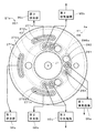
図1は、本発明の第1の実施の形態に係る基板処理装置1を示す断面図である。基板処理装置1は、略円板状の半導体基板9(以下、単に「基板9」という。)に処理液を供給して基板9を1枚ずつ処理する枚葉式の装置である。基板処理装置1では、純水、酸性の薬液、アルカリ性の薬液等が処理液として利用され、基板9の洗浄処理やその他の様々な処理が行われる。図1では、基板処理装置1の一部の構成の断面には、平行斜線の付与を省略している(他の断面図においても同様)。   FIG. 1 is a cross-sectional view showing a substrate processing apparatus 1 according to a first embodiment of the present invention. The substrate processing apparatus 1 is a single-wafer type apparatus that supplies a processing liquid to a substantially disk-shaped semiconductor substrate 9 (hereinafter simply referred to as “substrate 9”) to process the substrates 9 one by one. In the substrate processing apparatus 1, pure water, an acidic chemical solution, an alkaline chemical solution, or the like is used as a processing solution, and a cleaning process for the substrate 9 and other various processes are performed. In FIG. 1, the provision of parallel oblique lines is omitted in the cross section of a part of the configuration of the substrate processing apparatus 1 (the same applies to other cross sectional views).

基板処理装置1は、チャンバ21と、トッププレート22と、チャンバ開閉機構23と、基板保持部31と、基板回転機構32と、カップ部4と、カップ回転機構7と、処理液供給部5と、ハウジング6と、制御部10とを備える。なお、図2以降では、制御部10の図示を省略する。   The substrate processing apparatus 1 includes a chamber 21, a top plate 22, a chamber opening / closing mechanism 23, a substrate holding unit 31, a substrate rotating mechanism 32, a cup unit 4, a cup rotating mechanism 7, and a processing liquid supply unit 5. The housing 6 and the control unit 10 are provided. In FIG. 2 and subsequent figures, illustration of the control unit 10 is omitted.

ハウジング6の内部には、チャンバ21と、トッププレート22と、チャンバ開閉機構23と、基板保持部31と、基板回転機構32と、カップ部4と、処理液供給部5とが収容される。ハウジング6は、ハウジング底部61と、ハウジング側壁部62と、ハウジング天蓋部63とを備える。ハウジング6の底部であるハウジング底部61は、チャンバ21等を下方から支持する。ハウジング側壁部62は、チャンバ21等の周囲を囲む。ハウジング天蓋部63は、チャンバ21等の上方を覆う。ハウジング側壁部62には、基板9をハウジング6内に搬入するための搬入口64が設けられる。搬入口64は、上下方向に移動可能な蓋部65により閉塞される。   Inside the housing 6, a chamber 21, a top plate 22, a chamber opening / closing mechanism 23, a substrate holding unit 31, a substrate rotating mechanism 32, a cup unit 4, and a processing liquid supply unit 5 are accommodated. The housing 6 includes a housing bottom 61, a housing side wall 62, and a housing canopy 63. A housing bottom 61 that is the bottom of the housing 6 supports the chamber 21 and the like from below. The housing side wall 62 surrounds the chamber 21 and the like. The housing canopy 63 covers the top of the chamber 21 and the like. The housing side wall 62 is provided with a carry-in port 64 for carrying the substrate 9 into the housing 6. The carry-in port 64 is closed by a lid 65 that can move in the vertical direction.

チャンバ21は、チャンバ本体25と、チャンバ蓋部26とを備える。チャンバ21は、上下方向を向く中心軸J1を中心とする略円筒状である。チャンバ本体25は、チャンバ底部251と、チャンバ側壁部252とを備える。チャンバ底部251は、中央部254と、側壁部255と、外周部256とを備える。中央部254は、中心軸J1を中心とする略円環板状である。側壁部255は、中心軸J1を中心とする略円筒状であり、中央部254の外縁部から下方へと拡がる。外周部256は、中心軸J1を中心とする略円環板状であり、側壁部255の下端から、中心軸J1を中心とする径方向(以下、単に「径方向」という。)の外方へと拡がる。チャンバ側壁部252は、中心軸J1を中心とする略円筒状である。チャンバ側壁部252は、チャンバ底部251の外縁部から上方へと突出する。   The chamber 21 includes a chamber body 25 and a chamber lid portion 26. The chamber 21 has a substantially cylindrical shape centered on a central axis J1 that faces in the vertical direction. The chamber body 25 includes a chamber bottom 251 and a chamber side wall 252. The chamber bottom 251 includes a central part 254, a side wall part 255, and an outer peripheral part 256. The central portion 254 has a substantially annular plate shape centered on the central axis J1. The side wall portion 255 has a substantially cylindrical shape centered on the central axis J1, and extends downward from the outer edge portion of the central portion 254. The outer peripheral portion 256 has a substantially annular plate shape centered on the central axis J1 and is outward from the lower end of the side wall portion 255 in the radial direction centered on the central axis J1 (hereinafter simply referred to as “radial direction”). It spreads out. The chamber side wall part 252 has a substantially cylindrical shape centered on the central axis J1. The chamber side wall portion 252 protrudes upward from the outer edge portion of the chamber bottom portion 251.

チャンバ蓋部26は中心軸J1に垂直な略円環板状である。チャンバ蓋部26の外縁部下端がチャンバ側壁部252の上部と接することにより、チャンバ本体25の上部開口が閉塞される。チャンバ蓋部26がチャンバ本体25の上部開口を閉塞することにより、チャンバ21内に密閉空間であるチャンバ空間が形成される。換言すれば、チャンバ21は、チャンバ空間を形成する密閉空間形成部である。チャンバ21の内部であるチャンバ空間には、基板保持部31、トッププレート22およびカップ部4が収容される。   The chamber lid portion 26 has a substantially annular plate shape perpendicular to the central axis J1. The lower end of the outer edge of the chamber lid part 26 is in contact with the upper part of the chamber side wall part 252, thereby closing the upper opening of the chamber body 25. The chamber lid portion 26 closes the upper opening of the chamber body 25, whereby a chamber space that is a sealed space is formed in the chamber 21. In other words, the chamber 21 is a sealed space forming part that forms a chamber space. A substrate space 31, the top plate 22, and the cup portion 4 are accommodated in a chamber space that is inside the chamber 21.

チャンバ開閉機構23は、チャンバ21の可動部であるチャンバ蓋部26を、チャンバ21の他の部位であるチャンバ本体25に対して上下方向に相対的に移動する。チャンバ開閉機構23は、チャンバ蓋部26を昇降する蓋部昇降機構である。チャンバ開閉機構23によりチャンバ蓋部26が上下方向に移動する際には、トッププレート22がチャンバ蓋部26に吊り下げられた状態でチャンバ蓋部26と共に上下方向に移動する。チャンバ開閉機構23により、チャンバ蓋部26およびトッププレート22が、図1に示す位置から図2に示す位置へと上昇することにより、チャンバ21が開放される。以下の説明では、図1に示すチャンバ蓋部26およびトッププレート22の位置を「処理位置」という。また、図2に示すチャンバ蓋部26およびトッププレート22の位置を「退避位置」という。詳しくは後述するが、図2では、カップ部4のハウジング6に対する相対的な向き(すなわち、中心軸J1を中心とする周方向における相対的な向き)が図1とは異なる。   The chamber opening / closing mechanism 23 moves a chamber lid portion 26 that is a movable portion of the chamber 21 relative to the chamber main body 25 that is another part of the chamber 21 in the vertical direction. The chamber opening / closing mechanism 23 is a lid raising / lowering mechanism that raises and lowers the chamber lid 26. When the chamber lid 26 moves in the vertical direction by the chamber opening / closing mechanism 23, the top plate 22 moves in the vertical direction together with the chamber lid 26 while being suspended from the chamber lid 26. The chamber opening / closing mechanism 23 raises the chamber lid 26 and the top plate 22 from the position shown in FIG. 1 to the position shown in FIG. 2, thereby opening the chamber 21. In the following description, the positions of the chamber lid portion 26 and the top plate 22 shown in FIG. 1 are referred to as “processing positions”. Further, the positions of the chamber lid 26 and the top plate 22 shown in FIG. 2 are referred to as “retracted positions”. As will be described in detail later, in FIG. 2, the relative orientation of the cup portion 4 with respect to the housing 6 (that is, the relative orientation in the circumferential direction around the central axis J1) is different from FIG.

図1に示すトッププレート22は、中心軸J1を中心とする略円環板状であり、中央に開口を有する。トッププレート22は、プレート本体部224と、プレート側壁部225と、被保持部221とを備える。プレート本体部224は、中心軸J1を中心とする略円環板状である。プレート本体部224の中央部には略円形の開口が設けられ、当該開口の周囲に被保持部221が設けられる。プレート本体部224は、チャンバ蓋部26の下方、かつ、基板保持部31および基板9の上方に配置される。プレート本体部224の上面および下面は、中心軸J1から径方向に離れるに従って下方へと向かう傾斜面である。プレート本体部224の下面は、基板保持部31に保持された基板9の上面91と上下方向に対向する。   The top plate 22 shown in FIG. 1 has a substantially annular plate shape centered on the central axis J1, and has an opening at the center. The top plate 22 includes a plate body portion 224, a plate side wall portion 225, and a held portion 221. The plate body 224 has a substantially annular plate shape centered on the central axis J1. A substantially circular opening is provided at the center of the plate body 224, and a held portion 221 is provided around the opening. The plate body 224 is disposed below the chamber lid 26 and above the substrate holder 31 and the substrate 9. The upper surface and the lower surface of the plate body 224 are inclined surfaces that are directed downward as they are separated from the central axis J1 in the radial direction. The lower surface of the plate main body 224 faces the upper surface 91 of the substrate 9 held by the substrate holding unit 31 in the vertical direction.

プレート側壁部225は、プレート本体部224の外縁部から、径方向外方に向かって斜め下方に拡がる。換言すれば、プレート側壁部225は、プレート本体部224の外縁部からプレート本体部224の下面側へと突出し、中心軸J1から径方向に離れるに従って下方へと向かう。プレート側壁部225は、中心軸J1を中心とする略円筒状である。プレート側壁部225は、基板9の径方向外側に配置され、基板9の周囲を囲む。プレート側壁部225の下端は、上下方向において基板保持部31のベース部311(後述)とおよそ同じ位置に位置する。   The plate side wall part 225 extends obliquely downward from the outer edge part of the plate main body part 224 toward the radially outer side. In other words, the plate side wall part 225 protrudes from the outer edge part of the plate main body part 224 to the lower surface side of the plate main body part 224, and goes downward as it is separated from the central axis J1 in the radial direction. The plate side wall 225 has a substantially cylindrical shape centered on the central axis J1. The plate side wall part 225 is disposed on the outer side in the radial direction of the substrate 9 and surrounds the periphery of the substrate 9. The lower end of the plate side wall part 225 is positioned at approximately the same position as a base part 311 (described later) of the substrate holding part 31 in the vertical direction.

プレート本体部224の直径は、基板9の直径よりも大きい。プレート側壁部225の下端の直径は、基板保持部31のベース部311の直径よりも大きい。プレート側壁部225の下端は、ベース部311の外縁から径方向外側に全周に亘って離間する。トッププレート22は、基板9の外周縁、および、基板保持部31のベース部311の外周縁よりも全周に亘って径方向外側まで拡がる。   The diameter of the plate main body 224 is larger than the diameter of the substrate 9. The diameter of the lower end of the plate side wall part 225 is larger than the diameter of the base part 311 of the substrate holding part 31. The lower end of the plate side wall part 225 is spaced from the outer edge of the base part 311 to the outside in the radial direction over the entire circumference. The top plate 22 extends to the outside in the radial direction over the entire circumference from the outer peripheral edge of the substrate 9 and the outer peripheral edge of the base portion 311 of the substrate holding portion 31.

図2に示すように、退避位置に位置するトッププレート22は、チャンバ蓋部26により吊り下げられるように支持される。チャンバ蓋部26は、中央部に略環状のプレート保持部261を有する。プレート保持部261は、中心軸J1を中心とする略円筒状の筒部262と、中心軸J1を中心とする略円板状のフランジ部263とを備える。フランジ部263は、筒部262の下端から径方向内方へと拡がる。   As shown in FIG. 2, the top plate 22 located at the retracted position is supported so as to be suspended by the chamber lid portion 26. The chamber lid part 26 has a substantially annular plate holding part 261 at the center. The plate holding part 261 includes a substantially cylindrical tube part 262 centered on the central axis J1 and a substantially disk-shaped flange part 263 centered on the central axis J1. The flange part 263 extends radially inward from the lower end of the cylindrical part 262.

被保持部221は、プレート本体部224の中央部から上方に突出する略環状の部位である。被保持部221は、中心軸J1を中心とする略円筒状の筒部222と、中心軸J1を中心とする略円板状のフランジ部223とを備える。筒部222は、プレート本体部224の上面から上方に拡がる。フランジ部223は、筒部222の上端から径方向外方へと拡がる。筒部222は、プレート保持部261の筒部262の径方向内側に位置する。フランジ部223は、プレート保持部261のフランジ部263の上方に位置し、フランジ部263と上下方向に対向する。被保持部221のフランジ部223の下面が、プレート保持部261のフランジ部263の上面に接することにより、トッププレート22が、チャンバ蓋部26から吊り下がるようにチャンバ蓋部26に取り付けられる。   The held portion 221 is a substantially annular portion that protrudes upward from the central portion of the plate body portion 224. The held portion 221 includes a substantially cylindrical tube portion 222 centered on the central axis J1 and a substantially disk-shaped flange portion 223 centered on the central axis J1. The cylinder part 222 extends upward from the upper surface of the plate body part 224. The flange portion 223 extends radially outward from the upper end of the cylindrical portion 222. The cylindrical portion 222 is located on the radially inner side of the cylindrical portion 262 of the plate holding portion 261. The flange portion 223 is located above the flange portion 263 of the plate holding portion 261 and faces the flange portion 263 in the vertical direction. When the lower surface of the flange portion 223 of the held portion 221 is in contact with the upper surface of the flange portion 263 of the plate holding portion 261, the top plate 22 is attached to the chamber lid portion 26 so as to be suspended from the chamber lid portion 26.

図1に示すように、基板保持部31は、基板9を水平状態で保持する。すなわち、基板9は、微細パターンが形成された上面91を中心軸J1に垂直に上側を向く状態で基板保持部31により保持される。基板保持部31は、ベース部311と、複数のチャック312とを備える。ベース部311は、中心軸J1に垂直な略円板状であり、中央に開口を有する。複数(例えば、3つ)のチャック312は、ベース部311の上面に固定される。複数のチャック312は、中心軸J1を中心とする周方向(以下、単に「周方向」という。)におよそ等角度間隔にて配置される。複数のチャック312により、ベース部311の上方にて基板9の外縁部が保持される。   As shown in FIG. 1, the board | substrate holding part 31 hold | maintains the board | substrate 9 in a horizontal state. That is, the substrate 9 is held by the substrate holding part 31 with the upper surface 91 on which the fine pattern is formed facing upwards perpendicular to the central axis J1. The substrate holding part 31 includes a base part 311 and a plurality of chucks 312. The base portion 311 has a substantially disc shape perpendicular to the central axis J1, and has an opening at the center. A plurality of (for example, three) chucks 312 are fixed to the upper surface of the base portion 311. The plurality of chucks 312 are arranged at approximately equal angular intervals in the circumferential direction (hereinafter simply referred to as “circumferential direction”) centered on the central axis J1. The plurality of chucks 312 hold the outer edge portion of the substrate 9 above the base portion 311.

基板回転機構32は、チャンバ底部251の中央部254の下方に配置される。基板回転機構32は、例えば、軸回転型の電動モータである。基板回転機構32の回転軸321は、チャンバ底部251の中央部254を貫通してチャンバ21の内部へと延びる。回転軸321は、中心軸J1を中心とする略円筒状である。回転軸321の先端部には、基板保持部31のベース部311が固定される。回転軸321とチャンバ底部251の中央部254との間には、気体や液体の通過を防止するシールが設けられる。回転軸321が回転することにより、基板保持部31が基板9と共に中心軸J1を中心として回転する。   The substrate rotation mechanism 32 is disposed below the central portion 254 of the chamber bottom 251. The substrate rotation mechanism 32 is, for example, a shaft rotation type electric motor. The rotation shaft 321 of the substrate rotation mechanism 32 extends through the central portion 254 of the chamber bottom 251 and into the chamber 21. The rotation shaft 321 has a substantially cylindrical shape centered on the central axis J1. A base portion 311 of the substrate holding portion 31 is fixed to the distal end portion of the rotating shaft 321. A seal that prevents the passage of gas or liquid is provided between the rotating shaft 321 and the central portion 254 of the chamber bottom 251. By rotating the rotating shaft 321, the substrate holding portion 31 rotates around the central axis J <b> 1 together with the substrate 9.

基板保持部31のベース部311の上面には、複数の第1係合部314が周方向に設けられる。各第1係合部314は、上方に向かって突出する略柱状である。トッププレート22の下面には、複数の第2係合部226が周方向に設けられる。各第2係合部226の下部には、上方に向かって窪む凹部が設けられる。   A plurality of first engaging portions 314 are provided on the upper surface of the base portion 311 of the substrate holding portion 31 in the circumferential direction. Each first engagement portion 314 has a substantially columnar shape protruding upward. A plurality of second engaging portions 226 are provided on the lower surface of the top plate 22 in the circumferential direction. A concave portion that is recessed upward is provided at the lower portion of each second engagement portion 226.

トッププレート22が処理位置に位置する状態では、第2係合部226の下部の凹部に、第1係合部314が嵌る。これにより、トッププレート22は、周方向において基板保持部31のベース部311と係合する。換言すれば、第1係合部314および第2係合部226により、トッププレート22の基板保持部31に対する回転方向における相対位置が規制される。   In a state where the top plate 22 is located at the processing position, the first engagement portion 314 is fitted into the concave portion below the second engagement portion 226. Thereby, the top plate 22 engages with the base portion 311 of the substrate holding portion 31 in the circumferential direction. In other words, the first engagement portion 314 and the second engagement portion 226 regulate the relative position of the top plate 22 with respect to the substrate holding portion 31 in the rotation direction.

トッププレート22が処理位置に位置する状態では、トッププレート22は、第1係合部314および第2係合部226を介して、基板保持部31のベース部311に支持される。トッププレート22の被保持部221のフランジ部223は、チャンバ蓋部26のプレート保持部261のフランジ部263から上方に離間する。すなわち、被保持部221とプレート保持部261とは接触しておらず、プレート保持部261によるトッププレート22の保持は解除されている。このため、トッププレート22は、チャンバ蓋部26から独立して、基板保持部31および基板9と共に、基板回転機構32により回転する。第1係合部314および第2係合部226は、トッププレート22の回転時に、周方向においてトッププレート22の基板保持部31に対する相対位置を固定する位置固定部材である。   In a state where the top plate 22 is located at the processing position, the top plate 22 is supported by the base portion 311 of the substrate holding portion 31 via the first engaging portion 314 and the second engaging portion 226. The flange portion 223 of the held portion 221 of the top plate 22 is spaced upward from the flange portion 263 of the plate holding portion 261 of the chamber lid portion 26. That is, the held portion 221 and the plate holding portion 261 are not in contact, and the holding of the top plate 22 by the plate holding portion 261 is released. For this reason, the top plate 22 is rotated by the substrate rotating mechanism 32 together with the substrate holding unit 31 and the substrate 9 independently of the chamber lid 26. The first engagement portion 314 and the second engagement portion 226 are position fixing members that fix the relative position of the top plate 22 to the substrate holding portion 31 in the circumferential direction when the top plate 22 rotates.

処理液供給部5は、上部ノズル51と、下部ノズル52とを備える。上部ノズル51は、チャンバ蓋部26に固定され、トッププレート22の被保持部221の内側に配置される。上部ノズル51は、トッププレート22とは接触しておらず、トッププレート22が回転する際にも回転しない。上部ノズル51は、ハウジング6の外部に設けられた処理液供給源(図示省略)に接続される。上部ノズル51の下端は、基板9の上方に位置し、基板9の上面91の中央部に対向する。処理液供給源から上部ノズル51に供給された処理液は、上部ノズル51の下端から基板9の上面91上の中央部に向けて供給される。   The processing liquid supply unit 5 includes an upper nozzle 51 and a lower nozzle 52. The upper nozzle 51 is fixed to the chamber lid portion 26 and is disposed inside the held portion 221 of the top plate 22. The upper nozzle 51 is not in contact with the top plate 22 and does not rotate when the top plate 22 rotates. The upper nozzle 51 is connected to a processing liquid supply source (not shown) provided outside the housing 6. The lower end of the upper nozzle 51 is located above the substrate 9 and faces the center of the upper surface 91 of the substrate 9. The processing liquid supplied from the processing liquid supply source to the upper nozzle 51 is supplied from the lower end of the upper nozzle 51 toward the center on the upper surface 91 of the substrate 9.

下部ノズル52は、基板回転機構32の回転軸321の内側に配置され、基板保持部31のベース部311の中央に位置する開口を介して、ベース部311から上方に突出する。下部ノズル52は、回転軸321には接触しておらず、回転軸321が回転する際にも回転しない。下部ノズル52とベース部311との間には、気体や液体の通過を防止するシールが設けられている。下部ノズル52は、ハウジング6の外部に設けられた処理液供給源(図示省略)に接続される。下部ノズル52の上端は、基板9の下方に位置し、基板9の下面92の中央部に対向する。処理液供給源から下部ノズル52に供給された処理液は、下部ノズル52の上端から基板9の下面92の中央部に向けて供給される。   The lower nozzle 52 is disposed inside the rotation shaft 321 of the substrate rotating mechanism 32 and protrudes upward from the base portion 311 through an opening located at the center of the base portion 311 of the substrate holding portion 31. The lower nozzle 52 is not in contact with the rotating shaft 321 and does not rotate when the rotating shaft 321 rotates. A seal is provided between the lower nozzle 52 and the base 311 to prevent the passage of gas or liquid. The lower nozzle 52 is connected to a processing liquid supply source (not shown) provided outside the housing 6. The upper end of the lower nozzle 52 is located below the substrate 9 and faces the center of the lower surface 92 of the substrate 9. The processing liquid supplied from the processing liquid supply source to the lower nozzle 52 is supplied from the upper end of the lower nozzle 52 toward the center of the lower surface 92 of the substrate 9.

カップ部4は、中心軸J1を中心とする環状の部材である。カップ部4は、基板保持部31の下方に配置され、基板9からの処理液を受ける。カップ部4は、チャンバ底部251の側壁部255の径方向外側に位置し、側壁部255および基板回転機構32の周囲を囲む。   The cup part 4 is an annular member centered on the central axis J1. The cup unit 4 is disposed below the substrate holding unit 31 and receives the processing liquid from the substrate 9. The cup portion 4 is located on the radially outer side of the side wall portion 255 of the chamber bottom portion 251 and surrounds the side wall portion 255 and the substrate rotation mechanism 32.

カップ回転機構7は、いわゆる中空モータであり、中心軸J1を中心としてカップ部4を回転する。カップ回転機構7は、中心軸J1を中心とする環状のステータ部71と、環状のロータ部72とを備える。ロータ部72は、略円環状の永久磁石を含む。永久磁石の表面は、PTFE樹脂にてモールドされる。ロータ部72は、ハウジング6内においてカップ部4に取り付けられる。具体的には、ロータ部72は、チャンバ21内においてカップ底部42の外縁部近傍に取り付けられる。   The cup rotation mechanism 7 is a so-called hollow motor, and rotates the cup portion 4 about the central axis J1. The cup rotating mechanism 7 includes an annular stator portion 71 centered on the central axis J1 and an annular rotor portion 72. The rotor part 72 includes a substantially annular permanent magnet. The surface of the permanent magnet is molded with PTFE resin. The rotor portion 72 is attached to the cup portion 4 in the housing 6. Specifically, the rotor portion 72 is attached to the vicinity of the outer edge portion of the cup bottom portion 42 in the chamber 21.

ステータ部71は、チャンバ21外においてロータ部72の周囲、すなわち、径方向外側に配置される。図1に示す例では、ステータ部71は、チャンバ21の周囲において、ハウジング底部61上に固定される。ステータ部71は、中心軸J1を中心とする周方向に配列された複数のコイルを含む。   The stator portion 71 is disposed outside the chamber 21 and around the rotor portion 72, that is, radially outside. In the example shown in FIG. 1, the stator portion 71 is fixed on the housing bottom portion 61 around the chamber 21. Stator portion 71 includes a plurality of coils arranged in a circumferential direction around central axis J1.

ステータ部71に電流が供給されることにより、ステータ部71とロータ部72との間に、中心軸J1を中心とする回転力が発生する。これにより、ロータ部72が、中心軸J1を中心として水平状態で回転する。ステータ部71とロータ部72との間に働く磁力により、ロータ部72は、ハウジング6内のチャンバ21内において直接的にも間接的にもチャンバ21に接触することなく浮遊し、中心軸J1を中心としてカップ部4と共に浮遊状態にて回転する。基板処理装置1では、制御部10による制御により、カップ部4がカップ回転機構7により回転し、後述するカップ排液ポート451およびカップ排気ポート461の周方向の位置が決定される。   When current is supplied to the stator portion 71, a rotational force about the central axis J1 is generated between the stator portion 71 and the rotor portion 72. Thereby, the rotor part 72 rotates in a horizontal state around the central axis J1. Due to the magnetic force acting between the stator portion 71 and the rotor portion 72, the rotor portion 72 floats in the chamber 21 in the housing 6 without directly or indirectly contacting the chamber 21, and the central axis J1 is It rotates in a floating state with the cup part 4 as the center. In the substrate processing apparatus 1, the cup unit 4 is rotated by the cup rotating mechanism 7 under the control of the control unit 10, and the circumferential positions of the cup drain port 451 and the cup exhaust port 461 described later are determined.

カップ部4は、外側壁部41と、カップ底部42と、内側壁部43と、仕切り壁44とを備える。カップ部4の底部であるカップ底部42は、中心軸J1を中心とする略円環状である。外側壁部41は、中心軸J1を中心とする略円筒状である。外側壁部41は、カップ底部42の外周部から、中心軸J1に略平行に上方に拡がる。内側壁部43は、中心軸J1を中心とする略円筒状である。内側壁部43は、外側壁部41よりも径方向内側に位置し、カップ底部42の内周部から、中心軸J1に略平行に上方に拡がる。   The cup part 4 includes an outer wall part 41, a cup bottom part 42, an inner wall part 43, and a partition wall 44. The cup bottom 42 which is the bottom of the cup portion 4 has a substantially annular shape centering on the central axis J1. The outer wall portion 41 has a substantially cylindrical shape centered on the central axis J1. The outer wall portion 41 extends upward from the outer peripheral portion of the cup bottom portion 42 substantially parallel to the central axis J1. The inner wall portion 43 has a substantially cylindrical shape centered on the central axis J1. The inner wall portion 43 is located radially inward of the outer wall portion 41 and extends upward from the inner peripheral portion of the cup bottom portion 42 substantially parallel to the central axis J1.

仕切り壁44は、中心軸J1を中心とする略円筒状である。仕切り壁44は、径方向において内側壁部43と外側壁部41との間に位置し、カップ底部42から中心軸J1に略平行に上方に拡がる。以下の説明では、カップ部4の外側壁部41と仕切り壁44との間の空間を「外側カップ空間45」と呼ぶ。また、カップ部4の仕切り壁44と内側壁部43との間の空間を「内側カップ空間46」と呼ぶ。外側カップ空間45は、外側壁部41とカップ底部42と仕切り壁44とにより囲まれる略円筒状の空間である。内側カップ空間46は、仕切り壁44とカップ底部42と内側壁部43とにより囲まれる略円筒状の空間である。   The partition wall 44 has a substantially cylindrical shape centered on the central axis J1. The partition wall 44 is positioned between the inner wall portion 43 and the outer wall portion 41 in the radial direction, and extends upward from the cup bottom portion 42 substantially parallel to the central axis J1. In the following description, a space between the outer wall portion 41 and the partition wall 44 of the cup portion 4 is referred to as an “outer cup space 45”. The space between the partition wall 44 and the inner wall portion 43 of the cup portion 4 is referred to as an “inner cup space 46”. The outer cup space 45 is a substantially cylindrical space surrounded by the outer wall portion 41, the cup bottom portion 42, and the partition wall 44. The inner cup space 46 is a substantially cylindrical space surrounded by the partition wall 44, the cup bottom portion 42, and the inner wall portion 43.

内側カップ空間46は、基板保持部31のベース部311の下方に位置する。カップ底部42のうち内側カップ空間46の底部を構成する部位には、カップ排気ポート461が設けられる。換言すれば、カップ排気ポート461は仕切り壁44の下端よりも径方向内側に位置する。図1に示す状態では、カップ排気ポート461は、チャンバ底部251の外周部256に設けられたチャンバ排気ポート281と上下方向に重なる。カップ排気ポート461の下端は、チャンバ排気ポート281の上端と近接して上下方向に対向する。チャンバ21内の気体は、内側カップ空間46、カップ排気ポート461およびチャンバ排気ポート281を介してチャンバ21外かつハウジング6外に排出される。カップ排気ポート461の下端の大きさおよび形状は、チャンバ排気ポート281の上端の大きさおよび形状とおよそ同じである。換言すれば、カップ排気ポート461の下端の面積は、チャンバ排気ポート281の上端の面積とおよそ等しい。なお、カップ排気ポート461の下端の面積は、例えば、チャンバ排気ポート281の上端の面積よりも小さくてもよい。   The inner cup space 46 is located below the base portion 311 of the substrate holding portion 31. A cup exhaust port 461 is provided in a portion of the cup bottom 42 that forms the bottom of the inner cup space 46. In other words, the cup exhaust port 461 is located radially inward from the lower end of the partition wall 44. In the state shown in FIG. 1, the cup exhaust port 461 overlaps with the chamber exhaust port 281 provided in the outer peripheral portion 256 of the chamber bottom portion 251 in the vertical direction. The lower end of the cup exhaust port 461 is close to the upper end of the chamber exhaust port 281 and faces the vertical direction. The gas in the chamber 21 is discharged out of the chamber 21 and out of the housing 6 through the inner cup space 46, the cup exhaust port 461 and the chamber exhaust port 281. The size and shape of the lower end of the cup exhaust port 461 are approximately the same as the size and shape of the upper end of the chamber exhaust port 281. In other words, the area of the lower end of the cup exhaust port 461 is approximately equal to the area of the upper end of the chamber exhaust port 281. The area of the lower end of the cup exhaust port 461 may be smaller than the area of the upper end of the chamber exhaust port 281, for example.

図1に示す例では、カップ底部42のうち仕切り壁44の下端よりも径方向内側の部位に、下方に突出する略円筒状の底部突出部462が設けられ、カップ排気ポート461は底部突出部462内に設けられる。また、チャンバ底部251の外周部256に、上方に突出する略円筒状の底部突出部282が設けられ、チャンバ排気ポート281は底部突出部282内に設けられる。チャンバ排気ポート281は、ハウジング底部61を貫通してチャンバ空間外へと突出する。   In the example shown in FIG. 1, a substantially cylindrical bottom protrusion 462 that protrudes downward is provided in a portion of the cup bottom 42 that is radially inward of the lower end of the partition wall 44, and the cup exhaust port 461 is a bottom protrusion. 462 is provided. In addition, a substantially cylindrical bottom protruding portion 282 that protrudes upward is provided on the outer peripheral portion 256 of the chamber bottom portion 251, and the chamber exhaust port 281 is provided in the bottom protruding portion 282. The chamber exhaust port 281 passes through the housing bottom 61 and protrudes out of the chamber space.

外側カップ空間45は、内側カップ空間46よりも径方向外側にて、基板保持部31のベース部311の下方に位置する。カップ部4の外側壁部41は、基板9、基板保持部31およびトッププレート22よりも全周に亘って径方向外側に位置する。外側壁部41の上端は、上下方向において、基板保持部31のベース部311、および、トッププレート22のプレート側壁部225の下端とおよそ同じ位置に位置する。詳細には、外側壁部41の上端は、プレート側壁部225の下端よりも上方に位置する。すなわち、外側壁部41の上端部とプレート側壁部225の下端部とは、径方向に重なる。カップ部4の上端の直径は、プレート側壁部225の下端の直径よりも大きい。カップ部4の上端は、プレート側壁部225の下端から径方向外側に全周に亘って離間する。   The outer cup space 45 is located below the base portion 311 of the substrate holding portion 31 on the radially outer side of the inner cup space 46. The outer wall portion 41 of the cup portion 4 is located on the radially outer side over the entire circumference from the substrate 9, the substrate holding portion 31, and the top plate 22. The upper end of the outer side wall 41 is positioned at approximately the same position in the vertical direction as the base 311 of the substrate holding unit 31 and the lower end of the plate side wall 225 of the top plate 22. Specifically, the upper end of the outer wall portion 41 is located above the lower end of the plate side wall portion 225. That is, the upper end portion of the outer wall portion 41 and the lower end portion of the plate side wall portion 225 overlap in the radial direction. The upper end diameter of the cup part 4 is larger than the lower end diameter of the plate side wall part 225. The upper end of the cup part 4 is separated from the lower end of the plate side wall part 225 to the outer side in the radial direction over the entire circumference.

処理液供給部5から供給され、回転する基板9から飛散する処理液は、基板9の周囲に位置するプレート側壁部225により受けられ、プレート側壁部225の内周面上を下方に移動する。そして、プレート側壁部225から落下した処理液は、カップ部4の外側カップ空間45に流入する。すなわち、処理液供給部5からの処理液は、カップ部4の外側カップ空間45に流入する。   The processing liquid supplied from the processing liquid supply unit 5 and scattered from the rotating substrate 9 is received by the plate side wall part 225 located around the substrate 9 and moves downward on the inner peripheral surface of the plate side wall part 225. Then, the processing liquid dropped from the plate side wall portion 225 flows into the outer cup space 45 of the cup portion 4. That is, the processing liquid from the processing liquid supply unit 5 flows into the outer cup space 45 of the cup unit 4.

カップ底部42のうち外側カップ空間45の底部を構成する部位には、カップ排液ポート451が設けられる。換言すれば、カップ排液ポート451は仕切り壁44の下端よりも径方向外側に位置する。図1に示す状態では、カップ排液ポート451は、チャンバ底部251に設けられたチャンバ排液ポート271と上下方向に重なる。カップ排液ポート451の下端は、チャンバ排液ポート271の上端と近接して上下方向に対向する。そして、外側カップ空間45に流入した液体が、カップ排液ポート451およびチャンバ排液ポート271を介してチャンバ21外かつハウジング6外に排出される。カップ排液ポート451の下端の大きさおよび形状は、チャンバ排液ポート271の上端の大きさおよび形状とおよそ同じである。換言すれば、カップ排液ポート451の下端の面積は、チャンバ排液ポート271の上端の面積とおよそ等しい。なお、カップ排液ポート451の下端の面積は、例えば、チャンバ排液ポート271の上端の面積よりも小さくてもよい。   A cup drainage port 451 is provided at a portion of the cup bottom 42 that constitutes the bottom of the outer cup space 45. In other words, the cup drain port 451 is located on the radially outer side than the lower end of the partition wall 44. In the state shown in FIG. 1, the cup drain port 451 overlaps with the chamber drain port 271 provided in the chamber bottom 251 in the vertical direction. The lower end of the cup draining port 451 is close to the upper end of the chamber draining port 271 and faces the vertical direction. Then, the liquid flowing into the outer cup space 45 is discharged out of the chamber 21 and out of the housing 6 through the cup drain port 451 and the chamber drain port 271. The size and shape of the lower end of the cup drain port 451 are approximately the same as the size and shape of the upper end of the chamber drain port 271. In other words, the area of the lower end of the cup drain port 451 is approximately equal to the area of the upper end of the chamber drain port 271. The area of the lower end of the cup drain port 451 may be smaller than the area of the upper end of the chamber drain port 271, for example.

図1に示す例では、カップ底部42のうち仕切り壁44の下端よりも径方向外側の部位に、下方に突出する略円筒状の底部突出部452が設けられ、カップ排液ポート451は底部突出部452内に設けられる。また、チャンバ底部251の外周部256に、上方に突出する略円筒状の底部突出部272が設けられ、チャンバ排液ポート271は底部突出部272内に設けられる。チャンバ排液ポート271は、ハウジング底部61を貫通してチャンバ空間外へと突出する。   In the example shown in FIG. 1, a substantially cylindrical bottom protrusion 452 that protrudes downward is provided in a portion of the cup bottom 42 that is radially outward from the lower end of the partition wall 44, and the cup drainage port 451 protrudes from the bottom. Provided in the portion 452. In addition, a substantially cylindrical bottom protrusion 272 that protrudes upward is provided on the outer peripheral portion 256 of the chamber bottom 251, and the chamber drainage port 271 is provided in the bottom protrusion 272. The chamber drainage port 271 passes through the housing bottom 61 and protrudes out of the chamber space.

図3は、カップ部4を示す底面図である。カップ部4では、カップ排液ポート451およびカップ排気ポート461が、それぞれ1つずつカップ底部42に設けられる。図3では、図の理解を容易にするために、カップ排液ポート451およびカップ排気ポート461に平行斜線を付す(図12、図15および図19においても同様)。図3に示す例では、カップ排液ポート451は、中心軸J1を挟んでカップ排気ポート461の反対側に位置する。換言すれば、カップ排液ポート451とカップ排気ポート461とは、周方向において約180度間隔にて並ぶ。カップ排液ポート451は、カップ排気ポート461よりも径方向外側に位置する。   FIG. 3 is a bottom view showing the cup portion 4. In the cup portion 4, one cup drain port 451 and one cup exhaust port 461 are provided on the cup bottom 42 one by one. In FIG. 3, in order to facilitate understanding of the drawing, a parallel oblique line is given to the cup drain port 451 and the cup exhaust port 461 (the same applies to FIGS. 12, 15, and 19). In the example shown in FIG. 3, the cup drain port 451 is located on the opposite side of the cup exhaust port 461 across the central axis J1. In other words, the cup drain port 451 and the cup exhaust port 461 are arranged at intervals of about 180 degrees in the circumferential direction. The cup drain port 451 is located radially outside the cup exhaust port 461.

カップ底部42は、下方に突出する複数の外側凸部453、および、下方に突出する複数の内側凸部463を備える。複数の外側凸部453は、カップ排液ポート451が内部に設けられる底部突出部452と周方向に並ぶ(すなわち、中心軸J1からの径方向の距離が等しい円周上に並ぶ)。複数の内側凸部463は、カップ排気ポート461が内部に設けられる底部突出部462と周方向に並ぶ。図3に示す例では、15個の外側凸部453と、15個の内側凸部463とがカップ部4に設けられる。   The cup bottom 42 includes a plurality of outer protrusions 453 that protrude downward and a plurality of inner protrusions 463 that protrude downward. The plurality of outer convex portions 453 are arranged in the circumferential direction with the bottom protrusion 452 in which the cup drain port 451 is provided (that is, arranged on the circumference having the same radial distance from the central axis J1). The plurality of inner protrusions 463 are arranged in the circumferential direction with a bottom protrusion 462 in which the cup exhaust port 461 is provided. In the example shown in FIG. 3, 15 outer convex portions 453 and 15 inner convex portions 463 are provided on the cup portion 4.

各外側凸部453は略円柱状であり、各外側凸部453の直径は、カップ排液ポート451が内部に設けられる底部突出部452の外径におよそ等しい。各内側凸部463は略円柱状であり、各内側凸部463の直径は、カップ排気ポート461が内部に設けられる底部突出部462の外径におよそ等しい。各外側凸部453、各内側凸部463、底部突出部452および底部突出部462のカップ底部42からのそれぞれの突出量(すなわち、上下方向の高さ)は、互いにおよそ等しい。各外側凸部453および各内側凸部463の内部には流路は形成されておらず、各外側凸部453および各内側凸部463を介してカップ部4内の空間とカップ部4の下方の空間とは連通しない。   Each outer protrusion 453 is substantially cylindrical, and the diameter of each outer protrusion 453 is approximately equal to the outer diameter of the bottom protrusion 452 in which the cup drain port 451 is provided. Each inner convex portion 463 has a substantially cylindrical shape, and the diameter of each inner convex portion 463 is approximately equal to the outer diameter of the bottom protruding portion 462 in which the cup exhaust port 461 is provided. The respective protrusions (that is, the height in the vertical direction) of the outer protrusions 453, the inner protrusions 463, the bottom protrusions 452, and the bottom protrusions 462 from the cup bottom 42 are approximately equal to each other. No flow path is formed inside each outer convex portion 453 and each inner convex portion 463, and the space inside the cup portion 4 and below the cup portion 4 via each outer convex portion 453 and each inner convex portion 463. It does not communicate with the space.

図4は、チャンバ底部251を示す平面図である。図4では、カップ部4の外側壁部41、仕切り壁44および内側壁部43を破線にて併せて示す。チャンバ21では、複数のチャンバ排液ポート271、および、複数のチャンバ排気ポート281,284が、チャンバ底部251に設けられる。図4では、図の理解を容易にするために、チャンバ排液ポート271およびチャンバ排気ポート281,284に平行斜線を付す(図13、図16および図20においても同様)。   FIG. 4 is a plan view showing the chamber bottom 251. In FIG. 4, the outer side wall part 41 of the cup part 4, the partition wall 44, and the inner side wall part 43 are shown collectively with a broken line. In the chamber 21, a plurality of chamber drain ports 271 and a plurality of chamber exhaust ports 281 and 284 are provided in the chamber bottom 251. In FIG. 4, in order to facilitate understanding of the drawing, the chamber drain port 271 and the chamber exhaust ports 281 and 284 are hatched in parallel (the same applies to FIGS. 13, 16 and 20).

複数のチャンバ排液ポート271は、チャンバ底部251に設けられた複数の底部突出部272内にそれぞれ設けられる。複数のチャンバ排液ポート271は周方向に並ぶ。複数のチャンバ排液ポート271は同様の大きさおよび構造を有し、複数の底部突出部272も同様の大きさおよび構造を有する。   The plurality of chamber drain ports 271 are respectively provided in the plurality of bottom protrusions 272 provided in the chamber bottom 251. The plurality of chamber drain ports 271 are arranged in the circumferential direction. The plurality of chamber drain ports 271 have the same size and structure, and the plurality of bottom protrusions 272 also have the same size and structure.

複数のチャンバ排液ポート271は、複数のチャンバ排液ポート群を有する。図4に示す例では、チャンバ底部251に9個のチャンバ排液ポート271が設けられ、9個のチャンバ排液ポート271は、第1チャンバ排液ポート群276a、第2チャンバ排液ポート群276bおよび第3チャンバ排液ポート群276cを有する。以下の説明では、第1チャンバ排液ポート群276a、第2チャンバ排液ポート群276bおよび第3チャンバ排液ポート群276cをまとめて「チャンバ排液ポート群276a〜276c」ともいう。図4では、チャンバ排液ポート群276a〜276cをそれぞれ、二点鎖線にて囲む。   The plurality of chamber drainage ports 271 have a plurality of chamber drainage port groups. In the example shown in FIG. 4, nine chamber drain ports 271 are provided at the chamber bottom 251, and the nine chamber drain ports 271 include a first chamber drain port group 276 a and a second chamber drain port group 276 b. And a third chamber drain port group 276c. In the following description, the first chamber drain port group 276a, the second chamber drain port group 276b, and the third chamber drain port group 276c are collectively referred to as “chamber drain port groups 276a to 276c”. In FIG. 4, the chamber drainage port groups 276a to 276c are each surrounded by a two-dot chain line.

各チャンバ排液ポート群276a〜276cは、3個のチャンバ排液ポート271を有する。各チャンバ排液ポート群276a〜276cでは、3個のチャンバ排液ポート271が周方向に等角度間隔にて並ぶ。第1チャンバ排液ポート群276aの3個のチャンバ排液ポート271は、基板処理装置1の外部の第1排液部96aに接続される。第2チャンバ排液ポート群276bの3個のチャンバ排液ポート271は、基板処理装置1の外部の第2排液部96bに接続される。第3チャンバ排液ポート群276cの3個のチャンバ排液ポート271は、基板処理装置1の外部の第3排液部96cに接続される。第1排液部96a、第2排液部96bおよび第3排液部96cは、互いに独立して設けられる。   Each chamber drainage port group 276a-276c has three chamber drainage ports 271. In each chamber drain port group 276a to 276c, three chamber drain ports 271 are arranged at equal angular intervals in the circumferential direction. The three chamber drain ports 271 of the first chamber drain port group 276a are connected to the first drain unit 96a outside the substrate processing apparatus 1. The three chamber drain ports 271 of the second chamber drain port group 276b are connected to the second drain section 96b outside the substrate processing apparatus 1. The three chamber drain ports 271 of the third chamber drain port group 276c are connected to the third drain portion 96c outside the substrate processing apparatus 1. The first drainage part 96a, the second drainage part 96b, and the third drainage part 96c are provided independently of each other.

チャンバ底部251は、上方に突出する1つの外側凸部273を備える。外側凸部273は、複数のチャンバ排液ポート271がそれぞれ内部に設けられる複数の底部突出部272と周方向に並ぶ。外側凸部273は略円柱状であり、外側凸部273の直径は各底部突出部272の外径におよそ等しい。外側凸部273の内部には流路は形成されていない。   The chamber bottom 251 includes one outer protrusion 273 that protrudes upward. The outer convex portion 273 is arranged in the circumferential direction with a plurality of bottom protrusions 272 in which a plurality of chamber drain ports 271 are respectively provided. The outer convex portion 273 is substantially cylindrical, and the diameter of the outer convex portion 273 is approximately equal to the outer diameter of each bottom protruding portion 272. No flow path is formed inside the outer convex portion 273.

複数のチャンバ排気ポート281は、チャンバ底部251に設けられた複数の底部突出部282内にそれぞれ設けられる。また、複数のチャンバ排気ポート284は、チャンバ底部251に設けられて上方に突出する複数の底部突出部285内にそれぞれ設けられる。各チャンバ排気ポート284は、チャンバ排気ポート281に周方向において隣接する。以下の説明では、チャンバ排気ポート281,284の区別を容易にするために、チャンバ排気ポート281,284をそれぞれ、「大チャンバ排気ポート281」および「小チャンバ排気ポート284」と呼ぶ。また、大チャンバ排気ポート281および小チャンバ排気ポート284をまとめて、単に「チャンバ排気ポート」とも呼ぶ。   The plurality of chamber exhaust ports 281 are respectively provided in the plurality of bottom protrusions 282 provided in the chamber bottom 251. The plurality of chamber exhaust ports 284 are provided in the plurality of bottom protrusions 285 provided on the chamber bottom 251 and protruding upward. Each chamber exhaust port 284 is adjacent to the chamber exhaust port 281 in the circumferential direction. In the following description, the chamber exhaust ports 281 and 284 are referred to as a “large chamber exhaust port 281” and a “small chamber exhaust port 284” in order to facilitate the distinction between the chamber exhaust ports 281 and 284, respectively. Further, the large chamber exhaust port 281 and the small chamber exhaust port 284 are collectively referred to simply as a “chamber exhaust port”.

小チャンバ排気ポート284の直径は、大チャンバ排気ポート281の直径よりも小さい。換言すれば、小チャンバ排気ポート284の上端の面積は、大チャンバ排気ポート281の上端の面積よりも小さい。小チャンバ排気ポート284が内部に設けられる底部突出部285の外径は、大チャンバ排気ポート281が内部に設けられる底部突出部282の外径よりも小さい。複数の小チャンバ排気ポート284は、複数の大チャンバ排気ポート281と共に周方向に並ぶ。複数の大チャンバ排気ポート281は同様の大きさおよび構造を有し、複数の底部突出部282も同様の大きさおよび構造を有する。複数の小チャンバ排気ポート284は同様の大きさおよび構造を有し、複数の底部突出部285も同様の大きさおよび構造を有する。   The diameter of the small chamber exhaust port 284 is smaller than the diameter of the large chamber exhaust port 281. In other words, the area of the upper end of the small chamber exhaust port 284 is smaller than the area of the upper end of the large chamber exhaust port 281. The outer diameter of the bottom protrusion 285 in which the small chamber exhaust port 284 is provided is smaller than the outer diameter of the bottom protrusion 282 in which the large chamber exhaust port 281 is provided. The plurality of small chamber exhaust ports 284 are arranged in the circumferential direction together with the plurality of large chamber exhaust ports 281. The plurality of large chamber exhaust ports 281 have the same size and structure, and the plurality of bottom protrusions 282 have the same size and structure. The plurality of small chamber exhaust ports 284 have a similar size and structure, and the plurality of bottom protrusions 285 have a similar size and structure.

チャンバ底部251は、上方に突出する複数の内側凸部283を備える。複数の内側凸部283は、複数の底部突出部282および複数の底部突出部285と周方向に並ぶ。各内側凸部283は略円柱状であり、内側凸部283の直径は、大チャンバ排気ポート281が内部に設けられる底部突出部282の外径におよそ等しい。各内側凸部283の内部には流路は形成されていない。   The chamber bottom 251 includes a plurality of inner protrusions 283 that protrude upward. The plurality of inner protrusions 283 are arranged in the circumferential direction with the plurality of bottom protrusions 282 and the plurality of bottom protrusions 285. Each inner convex portion 283 is substantially cylindrical, and the diameter of the inner convex portion 283 is approximately equal to the outer diameter of the bottom protruding portion 282 in which the large chamber exhaust port 281 is provided. No flow path is formed inside each inner convex portion 283.

図4に示す例では、3個の大チャンバ排気ポート281と、3個の小チャンバ排気ポート284と、4個の内側凸部283とが、チャンバ底部251に設けられる。上述の第1チャンバ排液ポート群276aと中心軸J1を挟んで反対側に位置する第1チャンバ排気ポート群286aは、1つの大チャンバ排気ポート281と、1つの小チャンバ排気ポート284と、1つの内側凸部283とを有する。   In the example shown in FIG. 4, three large chamber exhaust ports 281, three small chamber exhaust ports 284, and four inner convex portions 283 are provided on the chamber bottom 251. The first chamber exhaust port group 276a located on the opposite side of the first chamber drain port group 276a with respect to the central axis J1 includes one large chamber exhaust port 281, one small chamber exhaust port 284, 1 And two inner convex portions 283.

第2チャンバ排液ポート群276bと中心軸J1を挟んで反対側に位置する第2チャンバ排気ポート群286bも、第1チャンバ排気ポート群286aと同様に、1つの大チャンバ排気ポート281と、1つの小チャンバ排気ポート284と、1つの内側凸部283とを有する。第3チャンバ排液ポート群276cと中心軸J1を挟んで反対側に位置する第3チャンバ排気ポート群286cも、第1チャンバ排気ポート群286aと同様に、1つの大チャンバ排気ポート281と、1つの小チャンバ排気ポート284と、1つの内側凸部283とを有する。   Similarly to the first chamber exhaust port group 286a, the second chamber exhaust port group 286b located on the opposite side of the second chamber drain port group 276b and the central axis J1 also has one large chamber exhaust port 281, 1 One small chamber exhaust port 284 and one inner convex portion 283 are provided. Similarly to the first chamber exhaust port group 286a, the third chamber exhaust port group 286c located on the opposite side of the third chamber drain port group 276c and the central axis J1 also has one large chamber exhaust port 281, 1 One small chamber exhaust port 284 and one inner convex portion 283 are provided.

以下の説明では、第1チャンバ排気ポート群286a、第2チャンバ排気ポート群286bおよび第3チャンバ排気ポート群286cをまとめて「チャンバ排気ポート群286a〜286c」ともいう。図4では、チャンバ排気ポート群286a〜286cをそれぞれ、二点鎖線にて囲む。各チャンバ排気ポート群286a〜286cでは、大チャンバ排気ポート281、小チャンバ排気ポート284および内側凸部283が周方向に等角度間隔にて並ぶ。4つの内側凸部283のうち1つの内側凸部283は、チャンバ排気ポート群286a〜286cには含まれておらず、外側凸部273と中心軸J1を挟んで反対側に位置する。   In the following description, the first chamber exhaust port group 286a, the second chamber exhaust port group 286b, and the third chamber exhaust port group 286c are collectively referred to as “chamber exhaust port groups 286a to 286c”. In FIG. 4, each of the chamber exhaust port groups 286a to 286c is surrounded by a two-dot chain line. In each chamber exhaust port group 286a to 286c, the large chamber exhaust port 281, the small chamber exhaust port 284 and the inner convex portion 283 are arranged at equal angular intervals in the circumferential direction. Of the four inner convex portions 283, one inner convex portion 283 is not included in the chamber exhaust port groups 286a to 286c, and is located on the opposite side across the outer convex portion 273 and the central axis J1.

第1チャンバ排気ポート群286aの大チャンバ排気ポート281および小チャンバ排気ポート284は、第1排気機構95aに接続される。第2チャンバ排気ポート群286bの大チャンバ排気ポート281および小チャンバ排気ポート284は、第2排気機構95bに接続される。第3チャンバ排気ポート群286cの大チャンバ排気ポート281および小チャンバ排気ポート284は、第3排気機構95cに接続される。第1排気機構95a、第2排気機構95bおよび第3排気機構95cは、基板処理装置1の外部に配置される。基板処理装置1が使用される間、第1排気機構95a、第2排気機構95bおよび第3排気機構95cによる吸引は、継続的に行われている。   The large chamber exhaust port 281 and the small chamber exhaust port 284 of the first chamber exhaust port group 286a are connected to the first exhaust mechanism 95a. The large chamber exhaust port 281 and the small chamber exhaust port 284 of the second chamber exhaust port group 286b are connected to the second exhaust mechanism 95b. The large chamber exhaust port 281 and the small chamber exhaust port 284 of the third chamber exhaust port group 286c are connected to the third exhaust mechanism 95c. The first exhaust mechanism 95a, the second exhaust mechanism 95b, and the third exhaust mechanism 95c are disposed outside the substrate processing apparatus 1. While the substrate processing apparatus 1 is in use, suction by the first exhaust mechanism 95a, the second exhaust mechanism 95b, and the third exhaust mechanism 95c is continuously performed.

基板処理装置1では、制御部10によりカップ回転機構7が制御されることにより、カップ排気ポート461が、複数の大チャンバ排気ポート281および複数の小チャンバ排気ポート284のうちいずれか1つに選択的に重ねられる。また、カップ排液ポート451が、複数のチャンバ排液ポート271のうちいずれか1つに選択的に重ねられる。   In the substrate processing apparatus 1, the cup exhaust port 461 is selected as one of a plurality of large chamber exhaust ports 281 and a plurality of small chamber exhaust ports 284 by controlling the cup rotating mechanism 7 by the control unit 10. Superimposed. Further, the cup drain port 451 is selectively overlapped with any one of the plurality of chamber drain ports 271.

図5は、基板処理装置1における基板9の処理の流れの一例を示す図である。基板処理装置1において基板9に対する処理が行われる際には、制御部10によりカップ回転機構7が制御されることにより、カップ部4が回転し、図2に示す向きにて停止する(ステップS11)。以下の説明では、図2に示すカップ部4の向き(すなわち、カップ部4の状態)を、「待機状態」という。   FIG. 5 is a diagram illustrating an example of a processing flow of the substrate 9 in the substrate processing apparatus 1. When processing the substrate 9 is performed in the substrate processing apparatus 1, the cup rotating mechanism 7 is controlled by the control unit 10, whereby the cup unit 4 rotates and stops in the direction shown in FIG. 2 (step S11). ). In the following description, the direction of the cup portion 4 shown in FIG. 2 (that is, the state of the cup portion 4) is referred to as a “standby state”.

図2に示す待機状態では、カップ排気ポート461は、チャンバ底部251の4つの内側凸部283のうち、チャンバ排気ポート群286a〜286c(図4参照)に含まれない1つの内側凸部283と上下方向に重なる。すなわち、図2では、カップ排気ポート461が、全ての大チャンバ排気ポート281および全ての小チャンバ排気ポート284(図4参照)から周方向に離間した位置に位置する状態を示す。カップ排気ポート461の下端とチャンバ底部251の内側凸部283の上端面とは、近接して上下方向に対向する。これにより、カップ排気ポート461が実質的に閉塞される。   In the standby state shown in FIG. 2, the cup exhaust port 461 includes one inner convex portion 283 that is not included in the chamber exhaust port groups 286a to 286c (see FIG. 4) among the four inner convex portions 283 of the chamber bottom portion 251. Overlapping in the vertical direction. That is, FIG. 2 shows a state in which the cup exhaust port 461 is located at a position spaced apart from all the large chamber exhaust ports 281 and all the small chamber exhaust ports 284 (see FIG. 4) in the circumferential direction. The lower end of the cup exhaust port 461 and the upper end surface of the inner convex portion 283 of the chamber bottom 251 are close to each other and face each other in the vertical direction. As a result, the cup exhaust port 461 is substantially closed.

また、カップ排液ポート451は、チャンバ底部251の外側凸部273と上下方向に重なる。カップ排液ポート451の下端と外側凸部273の上端面とは、上下方向に近接して対向する。これにより、カップ排液ポート451が実質的に閉塞される。   Further, the cup drain port 451 overlaps with the outer convex portion 273 of the chamber bottom 251 in the vertical direction. The lower end of the cup drain port 451 and the upper end surface of the outer convex portion 273 are opposed to each other in the vertical direction. As a result, the cup drain port 451 is substantially closed.

図2に示す待機状態では、第1チャンバ排気ポート群286aの大チャンバ排気ポート281が、カップ底部42の内側凸部463と上下方向に重なる。大チャンバ排気ポート281の上端と内側凸部463の下端面とは、上下方向に近接して対向する。これにより、大チャンバ排気ポート281が実質的に閉塞される。   In the standby state shown in FIG. 2, the large chamber exhaust port 281 of the first chamber exhaust port group 286 a overlaps the inner convex portion 463 of the cup bottom portion 42 in the vertical direction. The upper end of the large chamber exhaust port 281 and the lower end surface of the inner convex portion 463 face each other in the vertical direction. As a result, the large chamber exhaust port 281 is substantially closed.

図4に示す第1チャンバ排気ポート群286aの小チャンバ排気ポート284も、カップ底部42の内側凸部463と上下方向に重なる。小チャンバ排気ポート284の上端と内側凸部463の下端面とは、上下方向に近接して対向する。これにより、小チャンバ排気ポート284が実質的に閉塞される。第2チャンバ排気ポート群286bおよび第3チャンバ排気ポート群286cのそれぞれの大チャンバ排気ポート281および小チャンバ排気ポート284も同様に、内側凸部463とそれぞれ上下方向に近接して対向することにより、実質的に閉塞される。   The small chamber exhaust port 284 of the first chamber exhaust port group 286a shown in FIG. 4 also overlaps with the inner convex portion 463 of the cup bottom portion 42 in the vertical direction. The upper end of the small chamber exhaust port 284 and the lower end surface of the inner convex portion 463 face each other in the vertical direction. Thereby, the small chamber exhaust port 284 is substantially closed. Similarly, the large chamber exhaust port 281 and the small chamber exhaust port 284 of the second chamber exhaust port group 286b and the third chamber exhaust port group 286c respectively face the inner convex portion 463 close to each other in the vertical direction, It is substantially occluded.

また、各チャンバ排液ポート271は、カップ底部42の外側凸部453と上下方向に重なる。各チャンバ排液ポート271の上端と外側凸部453の下端面とは、上下方向に近接して対向する。これにより、各チャンバ排液ポート271が実質的に閉塞される。   Each chamber drain port 271 overlaps with the outer convex portion 453 of the cup bottom 42 in the vertical direction. The upper end of each chamber drainage port 271 and the lower end surface of the outer convex portion 453 are opposed to each other in the vertical direction. Thereby, each chamber drainage port 271 is substantially closed.

カップ部4が待機状態となると、チャンバ蓋部26およびトッププレート22が、図2に示す退避位置へと移動し、搬入口64が開放される。そして、搬入口64から基板9がハウジング6内のチャンバ21内に搬入され、基板保持部31により保持される(ステップS12)。   When the cup unit 4 enters the standby state, the chamber lid unit 26 and the top plate 22 move to the retracted position shown in FIG. 2, and the carry-in port 64 is opened. Then, the substrate 9 is carried into the chamber 21 in the housing 6 from the carry-in port 64 and is held by the substrate holding unit 31 (step S12).

上述のように、基板処理装置1では、カップ部4が待機状態の場合、カップ排気ポート461の下端がチャンバ底部251に近接し、各大チャンバ排気ポート281の上端および各小チャンバ排気ポート284の上端がカップ底部42に近接する。これにより、第1排気機構95a、第2排気機構95bおよび第3排気機構95c(図4参照)による吸引が継続されている状態であっても、カップ排気ポート461を介したカップ部4内の気体の吸引が実質的に停止される。その結果、基板9の搬入時に、ハウジング6の外部の気体が、開放された搬入口64からハウジング6内およびチャンバ21内に流入することを抑制することができる。   As described above, in the substrate processing apparatus 1, when the cup portion 4 is in the standby state, the lower end of the cup exhaust port 461 is close to the chamber bottom portion 251, and the upper end of each large chamber exhaust port 281 and each small chamber exhaust port 284. The upper end is close to the cup bottom 42. Thereby, even if the suction by the first exhaust mechanism 95a, the second exhaust mechanism 95b, and the third exhaust mechanism 95c (see FIG. 4) is continued, the inside of the cup portion 4 through the cup exhaust port 461 is maintained. The gas suction is substantially stopped. As a result, when the substrate 9 is carried in, the gas outside the housing 6 can be prevented from flowing into the housing 6 and the chamber 21 from the opened carry-in entrance 64.

なお、基板処理装置1では、カップ排気ポート461の下端がチャンバ底部251に近接するのであれば、必ずしも、各大チャンバ排気ポート281の上端および各小チャンバ排気ポート284の上端はカップ底部42に近接する必要はない。また、各大チャンバ排気ポート281の上端および各小チャンバ排気ポート284の上端がカップ底部42に近接するのであれば、必ずしもカップ排気ポート461の下端はチャンバ底部251に近接する必要はない。基板処理装置1では、カップ排気ポート461の下端がチャンバ底部251に近接することにより、または、各大チャンバ排気ポート281の上端および各小チャンバ排気ポート284の上端がカップ底部42に近接することにより、カップ排気ポート461を介したカップ部4内の気体の吸引が停止される。その結果、上記と同様に、ハウジング6の外部の気体が、開放された搬入口64からハウジング6内およびチャンバ21内に流入することを抑制することができる。   In the substrate processing apparatus 1, if the lower end of the cup exhaust port 461 is close to the chamber bottom 251, the upper end of each large chamber exhaust port 281 and the upper end of each small chamber exhaust port 284 are not necessarily close to the cup bottom 42. do not have to. Further, if the upper end of each large chamber exhaust port 281 and the upper end of each small chamber exhaust port 284 are close to the cup bottom 42, the lower end of the cup exhaust port 461 is not necessarily close to the chamber bottom 251. In the substrate processing apparatus 1, the lower end of the cup exhaust port 461 is close to the chamber bottom 251, or the upper end of each large chamber exhaust port 281 and the upper end of each small chamber exhaust port 284 are close to the cup bottom 42. The suction of the gas in the cup portion 4 through the cup exhaust port 461 is stopped. As a result, similarly to the above, the gas outside the housing 6 can be prevented from flowing into the housing 6 and the chamber 21 from the opened inlet 64.

基板9が保持されると、蓋部65が上方に移動し、図1に示すように搬入口64が閉塞される。また、チャンバ蓋部26およびトッププレート22が下降し、図1に示す処理位置に位置する。これにより、チャンバ21内にチャンバ空間が形成される。また、プレート保持部261によるトッププレート22の保持が解除される。チャンバ空間には、上部ノズル51等から窒素等の不活性ガスが供給される。   When the substrate 9 is held, the lid 65 moves upward, and the carry-in port 64 is closed as shown in FIG. Further, the chamber lid portion 26 and the top plate 22 are lowered and positioned at the processing position shown in FIG. Thereby, a chamber space is formed in the chamber 21. Further, the holding of the top plate 22 by the plate holding portion 261 is released. An inert gas such as nitrogen is supplied to the chamber space from the upper nozzle 51 or the like.

続いて、制御部10によりカップ回転機構7が制御されることにより、カップ部4が待機状態から回転し、図1に示す向きにて停止する(ステップS13)。以下の説明では、図1に示すカップ部4の向き(すなわち、カップ部4の状態)を、「第1処理状態」という。   Subsequently, when the cup rotating mechanism 7 is controlled by the control unit 10, the cup unit 4 rotates from the standby state and stops in the direction shown in FIG. 1 (step S13). In the following description, the direction of the cup part 4 shown in FIG. 1 (that is, the state of the cup part 4) is referred to as a “first processing state”.

図1に示す第1処理状態では、上述のように、カップ排気ポート461が、第1チャンバ排気ポート群286aの大チャンバ排気ポート281と上下方向に重なる。カップ排気ポート461の下端と当該大チャンバ排気ポート281の上端とは、近接して上下方向に対向する。これにより、カップ排気ポート461と第1チャンバ排気ポート群286aの大チャンバ排気ポート281とが、実質的に接続される。そして、第1排気機構95a(図4参照)により、カップ部4内の気体が、カップ排気ポート461および大チャンバ排気ポート281を介して、チャンバ21外かつハウジング6外に排出される。また、チャンバ21内のカップ部4外の気体も、内側カップ空間46、カップ排気ポート461および大チャンバ排気ポート281を介して、チャンバ21外かつハウジング6外に排出される。   In the first processing state shown in FIG. 1, as described above, the cup exhaust port 461 overlaps the large chamber exhaust port 281 of the first chamber exhaust port group 286a in the vertical direction. The lower end of the cup exhaust port 461 and the upper end of the large chamber exhaust port 281 are close to each other and face each other in the vertical direction. Thereby, the cup exhaust port 461 and the large chamber exhaust port 281 of the first chamber exhaust port group 286a are substantially connected. Then, the gas in the cup portion 4 is discharged out of the chamber 21 and out of the housing 6 through the cup exhaust port 461 and the large chamber exhaust port 281 by the first exhaust mechanism 95a (see FIG. 4). Further, the gas outside the cup portion 4 in the chamber 21 is also discharged out of the chamber 21 and out of the housing 6 through the inner cup space 46, the cup exhaust port 461 and the large chamber exhaust port 281.

カップ部4が第1処理状態の場合、図4に示す第1チャンバ排気ポート群286aの小チャンバ排気ポート284、第2チャンバ排気ポート群286bおよび第3チャンバ排気ポート群286cのそれぞれの大チャンバ排気ポート281および小チャンバ排気ポート284は、カップ底部42の内側凸部463(図3参照)と上下方向にそれぞれ重なり、実質的に閉塞される。   When the cup portion 4 is in the first processing state, the large chamber exhaust of each of the small chamber exhaust port 284, the second chamber exhaust port group 286b, and the third chamber exhaust port group 286c of the first chamber exhaust port group 286a shown in FIG. The port 281 and the small chamber exhaust port 284 overlap the inner convex portion 463 (see FIG. 3) of the cup bottom portion 42 in the vertical direction and are substantially closed.

図1に示すように、カップ排液ポート451は、第1チャンバ排液ポート群276aの中央のチャンバ排液ポート271と上下方向に重なる。カップ排液ポート451の下端と当該チャンバ排液ポート271の上端とは、近接して上下方向に対向する。これにより、カップ排液ポート451と第1チャンバ排液ポート群276aのチャンバ排液ポート271とが、実質的に接続される。当該チャンバ排液ポート271以外の各チャンバ排液ポート271(図4参照)は、カップ底部42の外側凸部453と上下方向に重なり、実質的に閉塞される。   As shown in FIG. 1, the cup drain port 451 overlaps with the chamber drain port 271 at the center of the first chamber drain port group 276a in the vertical direction. The lower end of the cup drain port 451 and the upper end of the chamber drain port 271 are close to each other and face each other in the vertical direction. As a result, the cup drain port 451 and the chamber drain port 271 of the first chamber drain port group 276a are substantially connected. Each chamber drain port 271 (see FIG. 4) other than the chamber drain port 271 overlaps the outer convex portion 453 of the cup bottom 42 in the vertical direction and is substantially closed.

カップ部4が第1処理状態となると、基板回転機構32が駆動され、基板9、基板保持部31およびトッププレート22の回転が開始される(ステップS14)。基板9、基板保持部31およびトッププレート22の回転速度は互いに等しく、回転方向は同じである。ステップS14は、ステップS13と並行して行われてもよく、ステップS12とステップS13との間に行われてもよい。   When the cup unit 4 is in the first processing state, the substrate rotation mechanism 32 is driven, and rotation of the substrate 9, the substrate holding unit 31, and the top plate 22 is started (step S14). The rotation speeds of the substrate 9, the substrate holding part 31, and the top plate 22 are equal to each other, and the rotation directions are the same. Step S14 may be performed in parallel with step S13, or may be performed between step S12 and step S13.

続いて、処理液供給部5の上部ノズル51から、回転中の基板9の上面91への第1処理液の供給が開始される(ステップS15)。基板9の上面91の中央部に連続的に供給された第1処理液は、遠心力により径方向外方へと移動する。第1処理液は、基板9の上面91上に拡がって上面91の全面を覆う。これにより、第1処理液による基板9の上面91に対する処理が行われる。基板9の上面91は、処理位置に位置するトッププレート22の下面と近接しているため、第1処理液による基板9の処理は、基板9の上面91とトッププレート22の下面との間の比較的狭い空間にて行われる。これにより、基板9の上方の空間における処理液雰囲気の拡散を抑制することができるとともに、処理中の基板9の温度低下を抑制することもできる。   Subsequently, the supply of the first processing liquid from the upper nozzle 51 of the processing liquid supply unit 5 to the upper surface 91 of the rotating substrate 9 is started (step S15). The first processing liquid continuously supplied to the center portion of the upper surface 91 of the substrate 9 moves outward in the radial direction by centrifugal force. The first processing liquid spreads on the upper surface 91 of the substrate 9 and covers the entire upper surface 91. Thereby, the process with respect to the upper surface 91 of the board | substrate 9 by a 1st process liquid is performed. Since the upper surface 91 of the substrate 9 is close to the lower surface of the top plate 22 located at the processing position, the processing of the substrate 9 by the first processing liquid is performed between the upper surface 91 of the substrate 9 and the lower surface of the top plate 22. It is performed in a relatively small space. Thereby, the diffusion of the processing liquid atmosphere in the space above the substrate 9 can be suppressed, and the temperature drop of the substrate 9 during processing can also be suppressed.

基板9の外周縁に到達した第1処理液は、当該外周縁から径方向外方へと飛散し、カップ部4の外側カップ空間45へと流入する。外側カップ空間45内に流入した第1処理液は、カップ排液ポート451およびチャンバ排液ポート271を介して、チャンバ21外かつハウジング6外の第1排液部96a(図4参照)へと排出される。第1排液部96aへと排出された第1処理液は廃棄される。あるいは、第1排液部96aへと排出された第1処理液は、必要に応じて回収されて再利用される。   The first processing liquid that has reached the outer peripheral edge of the substrate 9 scatters radially outward from the outer peripheral edge and flows into the outer cup space 45 of the cup portion 4. The first processing liquid that has flowed into the outer cup space 45 passes through the cup drain port 451 and the chamber drain port 271 to the first drain part 96a (see FIG. 4) outside the chamber 21 and outside the housing 6. Discharged. The 1st process liquid discharged | emitted to the 1st drainage part 96a is discarded. Or the 1st process liquid discharged | emitted to the 1st drainage part 96a is collect | recovered and reused as needed.

第1処理液による基板9の処理中は、チャンバ21内の気体は、上述のように、第1排気機構95aにより、内側カップ空間46、カップ排気ポート461および大チャンバ排気ポート281を介して、チャンバ21外かつハウジング6外に排出される。   During the processing of the substrate 9 by the first processing liquid, the gas in the chamber 21 is passed through the inner cup space 46, the cup exhaust port 461, and the large chamber exhaust port 281 by the first exhaust mechanism 95a as described above. It is discharged out of the chamber 21 and out of the housing 6.

上部ノズル51からの第1処理液の供給開始から所定時間が経過すると、第1処理液の供給が停止され、第1処理液による基板9の処理が終了する。基板9上に残っている第1処理液は、基板9の回転により基板9上から除去され、外側カップ空間45、カップ排液ポート451およびチャンバ排液ポート271を介して第1排液部96aへと排出される。   When a predetermined time has elapsed from the start of the supply of the first processing liquid from the upper nozzle 51, the supply of the first processing liquid is stopped and the processing of the substrate 9 by the first processing liquid is completed. The first processing liquid remaining on the substrate 9 is removed from the substrate 9 by the rotation of the substrate 9, and the first drainage portion 96 a is passed through the outer cup space 45, the cup drainage port 451, and the chamber drainage port 271. Is discharged.

第1処理液による処理が終了すると、制御部10によりカップ回転機構7が制御されることにより、カップ部4が第1処理状態から回転し、図6に示す向きにて停止する(ステップS16)。以下の説明では、図6に示すカップ部4の向き(すなわち、カップ部4の状態)を、「第2処理状態」という。   When the processing by the first processing liquid is completed, the cup rotating mechanism 7 is controlled by the control unit 10, whereby the cup unit 4 rotates from the first processing state and stops in the direction shown in FIG. 6 (step S16). . In the following description, the direction of the cup part 4 shown in FIG. 6 (that is, the state of the cup part 4) is referred to as “second processing state”.

図6に示す第2処理状態では、カップ排気ポート461が、第2チャンバ排気ポート群286bの大チャンバ排気ポート281と上下方向に重なる。カップ排気ポート461の下端と当該大チャンバ排気ポート281の上端とは、近接して上下方向に対向する。これにより、カップ排気ポート461と第2チャンバ排気ポート群286bの大チャンバ排気ポート281とが、実質的に接続される。そして、第2排気機構95b(図4参照)により、カップ部4内の気体が、カップ排気ポート461および大チャンバ排気ポート281を介して、チャンバ21外かつハウジング6外に排出される。また、カップ部4外の気体も、内側カップ空間46、カップ排気ポート461および大チャンバ排気ポート281を介して、チャンバ21外かつハウジング6外に排出される。   In the second processing state shown in FIG. 6, the cup exhaust port 461 overlaps the large chamber exhaust port 281 of the second chamber exhaust port group 286b in the vertical direction. The lower end of the cup exhaust port 461 and the upper end of the large chamber exhaust port 281 are close to each other and face each other in the vertical direction. Thereby, the cup exhaust port 461 and the large chamber exhaust port 281 of the second chamber exhaust port group 286b are substantially connected. Then, the gas in the cup portion 4 is discharged out of the chamber 21 and out of the housing 6 through the cup exhaust port 461 and the large chamber exhaust port 281 by the second exhaust mechanism 95b (see FIG. 4). Further, the gas outside the cup portion 4 is also discharged out of the chamber 21 and out of the housing 6 through the inner cup space 46, the cup exhaust port 461 and the large chamber exhaust port 281.

カップ部4が第2処理状態の場合、図4に示す第2チャンバ排気ポート群286bの小チャンバ排気ポート284、第1チャンバ排気ポート群286aおよび第3チャンバ排気ポート群286cのそれぞれの大チャンバ排気ポート281および小チャンバ排気ポート284は、カップ底部42の内側凸部463(図3参照)と上下方向にそれぞれ重なり、実質的に閉塞される。   When the cup portion 4 is in the second processing state, the large chamber exhaust of each of the small chamber exhaust port 284, the first chamber exhaust port group 286a, and the third chamber exhaust port group 286c of the second chamber exhaust port group 286b shown in FIG. The port 281 and the small chamber exhaust port 284 overlap the inner convex portion 463 (see FIG. 3) of the cup bottom portion 42 in the vertical direction and are substantially closed.

カップ排液ポート451は、第2チャンバ排液ポート群276bの中央のチャンバ排液ポート271と上下方向に重なる。カップ排液ポート451の下端と当該チャンバ排液ポート271の上端とは、近接して上下方向に対向する。これにより、カップ排液ポート451と第2チャンバ排液ポート群276bのチャンバ排液ポート271とが、実質的に接続される。当該チャンバ排液ポート271以外の各チャンバ排液ポート271(図4参照)は、カップ底部42の外側凸部453と上下方向に重なり、実質的に閉塞される。   The cup drain port 451 overlaps with the chamber drain port 271 at the center of the second chamber drain port group 276b in the vertical direction. The lower end of the cup drain port 451 and the upper end of the chamber drain port 271 are close to each other and face each other in the vertical direction. Thereby, the cup drainage port 451 and the chamber drainage port 271 of the second chamber drainage port group 276b are substantially connected. Each chamber drain port 271 (see FIG. 4) other than the chamber drain port 271 overlaps the outer convex portion 453 of the cup bottom 42 in the vertical direction and is substantially closed.

カップ部4が第2処理状態となると、処理液供給部5の上部ノズル51から、回転中の基板9の上面91への第2処理液の供給が開始される(ステップS17)。基板9の上面91の中央部に連続的に供給された第2処理液は、遠心力により基板9の上面91上に拡がって上面91の全面を覆う。これにより、第2処理液による基板9の上面91に対する処理が行われる。   When the cup unit 4 is in the second processing state, supply of the second processing liquid from the upper nozzle 51 of the processing liquid supply unit 5 to the upper surface 91 of the rotating substrate 9 is started (step S17). The second processing liquid continuously supplied to the central portion of the upper surface 91 of the substrate 9 spreads on the upper surface 91 of the substrate 9 by the centrifugal force and covers the entire surface of the upper surface 91. Thereby, the process with respect to the upper surface 91 of the board | substrate 9 by a 2nd process liquid is performed.

基板9の外周縁に到達した第2処理液は、当該外周縁から径方向外方へと飛散し、カップ部4の外側カップ空間45へと流入する。外側カップ空間45内に流入した第2処理液は、カップ排液ポート451およびチャンバ排液ポート271を介して、チャンバ21外かつハウジング6外の第2排液部96b(図4参照)へと排出される。第2排液部96aへと排出された第2処理液は廃棄される。あるいは、第2排液部96bへと排出された第2処理液は、必要に応じて回収されて再利用される。   The second processing liquid that has reached the outer peripheral edge of the substrate 9 scatters radially outward from the outer peripheral edge and flows into the outer cup space 45 of the cup portion 4. The second processing liquid that has flowed into the outer cup space 45 passes through the cup drain port 451 and the chamber drain port 271 to the second drain part 96b (see FIG. 4) outside the chamber 21 and outside the housing 6. Discharged. The second processing liquid discharged to the second drainage part 96a is discarded. Or the 2nd process liquid discharged | emitted to the 2nd drainage part 96b is collect | recovered and reused as needed.

第2処理液による基板9の処理中は、チャンバ21内の気体は、上述のように、第2排気機構95bにより、内側カップ空間46、カップ排気ポート461および大チャンバ排気ポート281を介して、チャンバ21外かつハウジング6外に排出される。   During the processing of the substrate 9 by the second processing liquid, the gas in the chamber 21 is passed through the inner cup space 46, the cup exhaust port 461, and the large chamber exhaust port 281 by the second exhaust mechanism 95b as described above. It is discharged out of the chamber 21 and out of the housing 6.

上部ノズル51からの第2処理液の供給開始から所定時間が経過すると、第2処理液の供給が停止され、第2処理液による基板9の処理が終了する。基板9上に残っている第2処理液は、基板9の回転により基板9上から除去され、外側カップ空間45、カップ排液ポート451およびチャンバ排液ポート271を介して第2排液部96bへと排出される。   When a predetermined time has elapsed from the start of the supply of the second processing liquid from the upper nozzle 51, the supply of the second processing liquid is stopped, and the processing of the substrate 9 by the second processing liquid is completed. The second processing liquid remaining on the substrate 9 is removed from the substrate 9 by the rotation of the substrate 9, and the second drainage part 96 b is passed through the outer cup space 45, the cup drainage port 451 and the chamber drainage port 271. Is discharged.

第2処理液による処理が終了すると、制御部10によりカップ回転機構7が制御されることにより、カップ部4が第2処理状態から回転し、図7に示す向きにて停止する(ステップS18)。以下の説明では、図7に示すカップ部4の向き(すなわち、カップ部4の状態)を、「第3処理状態」という。   When the processing by the second processing liquid is completed, the cup rotating mechanism 7 is controlled by the control unit 10, whereby the cup unit 4 rotates from the second processing state and stops in the direction shown in FIG. 7 (step S18). . In the following description, the direction of the cup part 4 shown in FIG. 7 (that is, the state of the cup part 4) is referred to as a “third processing state”.

図7に示す第3処理状態では、カップ排気ポート461が、第3チャンバ排気ポート群286cの大チャンバ排気ポート281と上下方向に重なる。カップ排気ポート461の下端と当該大チャンバ排気ポート281の上端とは、近接して上下方向に対向する。これにより、カップ排気ポート461と第3チャンバ排気ポート群286cの大チャンバ排気ポート281とが、実質的に接続される。そして、第3排気機構95c(図4参照)により、カップ部4内の気体が、カップ排気ポート461および大チャンバ排気ポート281を介して、チャンバ21外かつハウジング6外に排出される。また、チャンバ21内のカップ部4外の気体も、内側カップ空間46、カップ排気ポート461および大チャンバ排気ポート281を介して、チャンバ21外かつハウジング6外に排出される。   In the third processing state shown in FIG. 7, the cup exhaust port 461 overlaps the large chamber exhaust port 281 of the third chamber exhaust port group 286c in the vertical direction. The lower end of the cup exhaust port 461 and the upper end of the large chamber exhaust port 281 are close to each other and face each other in the vertical direction. Thereby, the cup exhaust port 461 and the large chamber exhaust port 281 of the third chamber exhaust port group 286c are substantially connected. Then, the gas in the cup portion 4 is discharged out of the chamber 21 and out of the housing 6 via the cup exhaust port 461 and the large chamber exhaust port 281 by the third exhaust mechanism 95c (see FIG. 4). Further, the gas outside the cup portion 4 in the chamber 21 is also discharged out of the chamber 21 and out of the housing 6 through the inner cup space 46, the cup exhaust port 461 and the large chamber exhaust port 281.

カップ部4が第3処理状態の場合、図4に示す第3チャンバ排気ポート群286cの小チャンバ排気ポート284、第1チャンバ排気ポート群286aおよび第2チャンバ排気ポート群286bのそれぞれの大チャンバ排気ポート281および小チャンバ排気ポート284は、カップ底部42の内側凸部463(図3参照)と上下方向にそれぞれ重なり、実質的に閉塞される。   When the cup portion 4 is in the third processing state, the large chamber exhaust of each of the small chamber exhaust port 284, the first chamber exhaust port group 286a, and the second chamber exhaust port group 286b of the third chamber exhaust port group 286c shown in FIG. The port 281 and the small chamber exhaust port 284 overlap the inner convex portion 463 (see FIG. 3) of the cup bottom portion 42 in the vertical direction and are substantially closed.

カップ排液ポート451は、第3チャンバ排液ポート群276cの中央のチャンバ排液ポート271と上下方向に重なる。カップ排液ポート451の下端と当該チャンバ排液ポート271の上端とは、近接して上下方向に対向する。これにより、カップ排液ポート451と第3チャンバ排液ポート群276cのチャンバ排液ポート271とが、実質的に接続される。当該チャンバ排液ポート271以外の各チャンバ排液ポート271(図4参照)は、カップ底部42の外側凸部453と上下方向に重なり、実質的に閉塞される。   The cup drain port 451 overlaps with the chamber drain port 271 at the center of the third chamber drain port group 276c in the vertical direction. The lower end of the cup drain port 451 and the upper end of the chamber drain port 271 are close to each other and face each other in the vertical direction. As a result, the cup drain port 451 and the chamber drain port 271 of the third chamber drain port group 276c are substantially connected. Each chamber drain port 271 (see FIG. 4) other than the chamber drain port 271 overlaps the outer convex portion 453 of the cup bottom 42 in the vertical direction and is substantially closed.

カップ部4が第3処理状態となると、処理液供給部5の上部ノズル51から、回転中の基板9の上面91への第3処理液の供給が開始される(ステップS19)。基板9の上面91の中央部に連続的に供給された第3処理液は、遠心力により基板9の上面91上に拡がって上面91の全面を覆う。これにより、第3処理液による基板9の上面91に対する処理が行われる。   When the cup unit 4 enters the third processing state, the supply of the third processing liquid from the upper nozzle 51 of the processing liquid supply unit 5 to the upper surface 91 of the rotating substrate 9 is started (step S19). The third processing liquid continuously supplied to the central portion of the upper surface 91 of the substrate 9 spreads on the upper surface 91 of the substrate 9 by the centrifugal force and covers the entire upper surface 91. Thereby, the process with respect to the upper surface 91 of the board | substrate 9 by a 3rd process liquid is performed.

基板9の外周縁に到達した第3処理液は、当該外周縁から径方向外方へと飛散し、カップ部4の外側カップ空間45へと流入する。外側カップ空間45内に流入した第3処理液は、カップ排液ポート451およびチャンバ排液ポート271を介して、チャンバ21外かつハウジング6外の第3排液部96c(図4参照)へと排出される。第3排液部96cへと排出された第3処理液は廃棄される。あるいは、第3排液部96cへと排出された第3処理液は、必要に応じて回収されて再利用される。   The third processing liquid that has reached the outer peripheral edge of the substrate 9 scatters radially outward from the outer peripheral edge and flows into the outer cup space 45 of the cup portion 4. The third processing liquid that has flowed into the outer cup space 45 passes through the cup drain port 451 and the chamber drain port 271 to the third drain part 96c (see FIG. 4) outside the chamber 21 and outside the housing 6. Discharged. The third processing liquid discharged to the third drainage part 96c is discarded. Alternatively, the third processing liquid discharged to the third drainage unit 96c is collected and reused as necessary.

第3処理液による基板9の処理中は、チャンバ21内の気体は、上述のように、第3排気機構95cにより、内側カップ空間46、カップ排気ポート461および大チャンバ排気ポート281を介して、チャンバ21外かつハウジング6外に排出される。   During the processing of the substrate 9 by the third processing liquid, the gas in the chamber 21 is passed through the inner cup space 46, the cup exhaust port 461, and the large chamber exhaust port 281 by the third exhaust mechanism 95c as described above. It is discharged out of the chamber 21 and out of the housing 6.

上部ノズル51からの第3処理液の供給開始から所定時間が経過すると、第3処理液の供給が停止され、第3処理液による基板9の処理が終了する。基板9上に残っている第3処理液は、基板9の回転により基板9上から除去され、外側カップ空間45、カップ排液ポート451およびチャンバ排液ポート271を介して第3排液部96cへと排出される。   When a predetermined time has elapsed from the start of the supply of the third processing liquid from the upper nozzle 51, the supply of the third processing liquid is stopped, and the processing of the substrate 9 by the third processing liquid is completed. The third processing liquid remaining on the substrate 9 is removed from the substrate 9 by the rotation of the substrate 9, and the third drainage part 96c is passed through the outer cup space 45, the cup drainage port 451, and the chamber drainage port 271. Is discharged.

基板9上から第3処理液が除去されると、基板9、基板保持部31およびトッププレート22の回転が停止される(ステップS20)。続いて、制御部10によりカップ回転機構7が制御されることにより、カップ部4が回転し、図2に示す待機状態となる(ステップS21)。ステップS21は、ステップS20と並行して行われてもよい。カップ部4が待機状態となると、チャンバ蓋部26およびトッププレート22が上昇し、図2に示す退避位置に位置する。その後、蓋部65が下方に移動して搬入口64が開放され、基板9が基板処理装置1から搬出される(ステップS22)。   When the third processing liquid is removed from the substrate 9, the rotation of the substrate 9, the substrate holding unit 31, and the top plate 22 is stopped (step S20). Subsequently, the cup rotating mechanism 7 is controlled by the control unit 10, whereby the cup unit 4 rotates and enters a standby state shown in FIG. 2 (step S21). Step S21 may be performed in parallel with step S20. When the cup unit 4 enters the standby state, the chamber lid unit 26 and the top plate 22 are raised and are positioned at the retracted position shown in FIG. Thereafter, the lid 65 moves downward, the carry-in port 64 is opened, and the substrate 9 is carried out of the substrate processing apparatus 1 (step S22).

上述のように、基板処理装置1では、カップ部4が待機状態の場合、カップ排気ポート461の下端がチャンバ底部251に近接し、各大チャンバ排気ポート281の上端および各小チャンバ排気ポート284の上端がカップ底部42に近接する。これにより、第1排気機構95a、第2排気機構95bおよび第3排気機構95c(図4参照)による吸引が継続されている状態であっても、カップ排気ポート461を介したカップ部4内の気体の吸引が実質的に停止される。その結果、基板9の搬出時に、ハウジング6の外部の気体が、開放された搬入口64からハウジング6内およびチャンバ21内に流入することを抑制することができる。   As described above, in the substrate processing apparatus 1, when the cup portion 4 is in the standby state, the lower end of the cup exhaust port 461 is close to the chamber bottom portion 251, and the upper end of each large chamber exhaust port 281 and each small chamber exhaust port 284. The upper end is close to the cup bottom 42. Thereby, even if the suction by the first exhaust mechanism 95a, the second exhaust mechanism 95b, and the third exhaust mechanism 95c (see FIG. 4) is continued, the inside of the cup portion 4 through the cup exhaust port 461 is maintained. The gas suction is substantially stopped. As a result, when the substrate 9 is unloaded, the gas outside the housing 6 can be prevented from flowing into the housing 6 and the chamber 21 from the opened loading port 64.

以上に説明したように、基板処理装置1では、周方向に並ぶ複数の大チャンバ排気ポート281がチャンバ底部251に設けられる。そして、制御部10がカップ回転機構7を制御することにより、カップ排気ポート461が、複数の大チャンバ排気ポート281のいずれか1つに選択的に重ねられる。カップ排気ポート461が第1チャンバ排気ポート群286aの大チャンバ排気ポート281に重なる状態では、第1排気機構95aにより、カップ部4内の気体がカップ排気ポート461および当該大チャンバ排気ポート281を介してチャンバ21外かつハウジング6外に排出される。   As described above, in the substrate processing apparatus 1, a plurality of large chamber exhaust ports 281 arranged in the circumferential direction are provided in the chamber bottom 251. The controller 10 controls the cup rotating mechanism 7 so that the cup exhaust port 461 is selectively overlapped with any one of the plurality of large chamber exhaust ports 281. In a state where the cup exhaust port 461 overlaps the large chamber exhaust port 281 of the first chamber exhaust port group 286a, the gas in the cup portion 4 is passed through the cup exhaust port 461 and the large chamber exhaust port 281 by the first exhaust mechanism 95a. Then, it is discharged out of the chamber 21 and out of the housing 6.

また、カップ排気ポート461が第2チャンバ排気ポート群286bの大チャンバ排気ポート281に重なる状態では、第2排気機構95bにより、カップ部4内の気体がカップ排気ポート461および当該大チャンバ排気ポート281を介してチャンバ21外かつハウジング6外に排出される。さらに、カップ排気ポート461が第3チャンバ排気ポート群286cの大チャンバ排気ポート281に重なる状態では、第3排気機構95cにより、カップ部4内の気体がカップ排気ポート461および当該大チャンバ排気ポート281を介してチャンバ21外かつハウジング6外に排出される。   In the state where the cup exhaust port 461 overlaps the large chamber exhaust port 281 of the second chamber exhaust port group 286b, the gas in the cup portion 4 is caused to flow from the cup exhaust port 461 and the large chamber exhaust port 281 by the second exhaust mechanism 95b. Is discharged out of the chamber 21 and out of the housing 6. Further, in a state where the cup exhaust port 461 overlaps the large chamber exhaust port 281 of the third chamber exhaust port group 286c, the gas in the cup portion 4 is caused to flow from the cup exhaust port 461 and the large chamber exhaust port 281 by the third exhaust mechanism 95c. Is discharged out of the chamber 21 and out of the housing 6.

このように、基板処理装置1では、カップ回転機構7により、チャンバ21およびハウジング6を開放することなくチャンバ21内かつハウジング6内のカップ部4を回転させることにより、カップ部4からの排気を行う排気機構を、第1排気機構95a、第2排気機構95bおよび第3排気機構95cの間で容易に切り替えることができる。また、カップ部からの排気の送出先(以下、「排気先」という。)を、簡素な構造の機構にて切り替えることができるため、基板処理装置1の構造を簡素化することができる。これにより、カップ部からの排気先を切り替える切替器をハウジングの外部に設ける場合に比べ、基板処理装置1を小型化することができる。さらに、カップ部4からの排気先をチャンバ21内にて切り替えることにより、ハウジング外の切替器まで共通配管等により排気を導く場合に比べ、排気中のガス状やミスト状の処理液が混蝕することを抑制することができる。   As described above, in the substrate processing apparatus 1, the cup rotation mechanism 7 rotates the cup portion 4 in the chamber 21 and the housing 6 without opening the chamber 21 and the housing 6, thereby exhausting the exhaust from the cup portion 4. The exhaust mechanism to be performed can be easily switched among the first exhaust mechanism 95a, the second exhaust mechanism 95b, and the third exhaust mechanism 95c. In addition, since the exhaust destination from the cup portion (hereinafter referred to as “exhaust destination”) can be switched by a mechanism having a simple structure, the structure of the substrate processing apparatus 1 can be simplified. Thereby, the substrate processing apparatus 1 can be reduced in size compared with the case where the switch which switches the exhaust destination from a cup part is provided in the exterior of a housing. Further, by switching the exhaust destination from the cup portion 4 in the chamber 21, compared to the case where exhaust is guided by a common pipe or the like to the switch outside the housing, the gaseous or mist processing liquid in the exhaust is mixed. Can be suppressed.

上述のように、基板処理装置1では、周方向に並ぶ複数のチャンバ排液ポート271がチャンバ底部251に設けられる。カップ排気ポート461が第1チャンバ排気ポート群286aの大チャンバ排気ポート281に重ねられた状態では、カップ排液ポート451は、第1チャンバ排液ポート群276aの中央のチャンバ排液ポート271と重なる。そして、カップ部4内に流入した第1処理液は、カップ排液ポート451と当該チャンバ排液ポート271とを介して、チャンバ21外かつハウジング6外の第1排液部96aへと排出される。   As described above, in the substrate processing apparatus 1, the plurality of chamber drain ports 271 arranged in the circumferential direction are provided in the chamber bottom 251. In a state where the cup exhaust port 461 is overlapped with the large chamber exhaust port 281 of the first chamber exhaust port group 286a, the cup drain port 451 overlaps with the central chamber drain port 271 of the first chamber drain port group 276a. . Then, the first processing liquid flowing into the cup portion 4 is discharged to the first drainage portion 96a outside the chamber 21 and outside the housing 6 through the cup drainage port 451 and the chamber drainage port 271. The

また、カップ排気ポート461が第2チャンバ排気ポート群286bの大チャンバ排気ポート281に重ねられた状態では、カップ排液ポート451は、第2チャンバ排液ポート群276bの中央のチャンバ排液ポート271と重なる。カップ部4内に流入した第2処理液は、カップ排液ポート451と当該チャンバ排液ポート271とを介して、チャンバ21外かつハウジング6外の第2排液部96bへと排出される。カップ排気ポート461が第3チャンバ排気ポート群286cの大チャンバ排気ポート281に重ねられた状態では、カップ排液ポート451は、第3チャンバ排液ポート群276cの中央のチャンバ排液ポート271と重なる。カップ部4内に流入した第3処理液は、カップ排液ポート451と当該チャンバ排液ポート271とを介して、チャンバ21外かつハウジング6外の第3排液部96cへと排出される。   Further, in the state where the cup exhaust port 461 is overlapped with the large chamber exhaust port 281 of the second chamber exhaust port group 286b, the cup drain port 451 is the center chamber drain port 271 of the second chamber drain port group 276b. And overlap. The second processing liquid that has flowed into the cup portion 4 is discharged to the second drainage portion 96 b outside the chamber 21 and outside the housing 6 via the cup drainage port 451 and the chamber drainage port 271. In a state where the cup exhaust port 461 is overlapped with the large chamber exhaust port 281 of the third chamber exhaust port group 286c, the cup drain port 451 overlaps with the central chamber drain port 271 of the third chamber drain port group 276c. . The third processing liquid that has flowed into the cup portion 4 is discharged to the third drainage portion 96 c outside the chamber 21 and outside the housing 6 via the cup drainage port 451 and the chamber drainage port 271.

このように、基板処理装置1では、カップ回転機構7によりカップ部4を回転させることにより、カップ部4からの排気先の切り替えと、カップ部4からの処理液の送出先(以下、「排液先」という。)の切り替えとを、1つの機構にて同時に行うことができる。その結果、基板処理装置1の構造を簡素化することができるとともに、基板処理装置1を小型化することができる。   As described above, in the substrate processing apparatus 1, the cup unit 4 is rotated by the cup rotating mechanism 7, thereby switching the exhaust destination from the cup unit 4 and the destination of the processing liquid from the cup unit 4 (hereinafter referred to as “exhaust”). “Liquid tip”)) can be switched simultaneously by one mechanism. As a result, the structure of the substrate processing apparatus 1 can be simplified, and the substrate processing apparatus 1 can be downsized.

カップ部4では、内側壁部43と外側壁部41との間に仕切り壁44が設けられ、処理液供給部5からの処理液は、外側壁部41と仕切り壁44との間の外側カップ空間45に流入する。また、カップ排液ポート451は仕切り壁44の下端よりも径方向外側に位置し、カップ排気ポート461は仕切り壁44の下端よりも径方向内側に位置する。これにより、カップ排気ポート461に処理液が流入することを、簡素な構成で防止または抑制することができる。   In the cup part 4, a partition wall 44 is provided between the inner wall part 43 and the outer wall part 41, and the processing liquid from the processing liquid supply part 5 is supplied to the outer cup between the outer wall part 41 and the partition wall 44. It flows into the space 45. Further, the cup drain port 451 is located radially outside the lower end of the partition wall 44, and the cup exhaust port 461 is located radially inside the lower end of the partition wall 44. Thereby, it is possible to prevent or suppress the processing liquid from flowing into the cup exhaust port 461 with a simple configuration.

基板処理装置1では、ロータ部72がハウジング6内に配置され、ステータ部71がハウジング6外に配置される。このため、ハウジング6の搬入口64を閉鎖した状態で、カップ部4を回転させてカップ排液ポート451およびカップ排気ポート461の位置を変更することができる。また、ハウジング6の内部空間を小型化することもできる。さらに、ステータ部71がロータ部72の周囲に配置されることにより、ハウジング6の中央部下方の空間に、基板回転機構32や下部ノズル52等の他の構成を容易に配置することができる。   In the substrate processing apparatus 1, the rotor portion 72 is disposed in the housing 6, and the stator portion 71 is disposed outside the housing 6. For this reason, it is possible to change the positions of the cup drain port 451 and the cup exhaust port 461 by rotating the cup portion 4 with the carry-in port 64 of the housing 6 closed. In addition, the internal space of the housing 6 can be reduced in size. Furthermore, by disposing the stator portion 71 around the rotor portion 72, other configurations such as the substrate rotation mechanism 32 and the lower nozzle 52 can be easily disposed in the space below the central portion of the housing 6.

上述のように、ロータ部72はチャンバ21内に配置されるため、チャンバ21を密閉してチャンバ空間を維持した状態で、カップ部4を回転させてカップ排液ポート451およびカップ排気ポート461の位置を変更することができる。また、ステータ部71はチャンバ21外に配置されるため、チャンバ空間を小型化することもできる。   As described above, since the rotor portion 72 is disposed in the chamber 21, the cup portion 4 is rotated and the cup drain port 451 and the cup exhaust port 461 are rotated while the chamber 21 is sealed and the chamber space is maintained. The position can be changed. Moreover, since the stator part 71 is arrange | positioned out of the chamber 21, chamber space can also be reduced in size.

基板処理装置1では、ロータ部72は、ハウジング6内のチャンバ空間において浮遊状態にて回転する。このため、ロータ部72を支持する構造をチャンバ空間に設ける必要がなく、基板処理装置1の小型化および装置構造の簡素化が実現される。また、当該支持構造に処理液が付着することがないため、付着した処理液の乾燥によるパーティクル等の発生を防止することができる。さらに、ロータ部72と支持構造との摩擦によりパーティクル等が発生することもないため、チャンバ空間およびハウジング6内の清浄性を向上することができる。   In the substrate processing apparatus 1, the rotor portion 72 rotates in a floating state in the chamber space in the housing 6. For this reason, it is not necessary to provide a structure for supporting the rotor portion 72 in the chamber space, and the substrate processing apparatus 1 can be downsized and the apparatus structure can be simplified. Further, since the processing liquid does not adhere to the support structure, generation of particles or the like due to drying of the attached processing liquid can be prevented. Further, since particles and the like are not generated due to friction between the rotor portion 72 and the support structure, the cleanliness of the chamber space and the housing 6 can be improved.

基板処理装置1では、例えば、チャンバ空間に窒素ガスを充填する場合等、第1排気機構95aによるチャンバ21からの排気流量を小さくして窒素の消費量を低減することが求められる場合がある。この場合、カップ回転機構7が制御部10により制御され、図8に示すように、カップ排気ポート461が第1チャンバ排気ポート群286aの小チャンバ排気ポート284に上下方向に重ねられる。カップ排気ポート461は小チャンバ排気ポート284に近接して上下方向に対向する。これにより、カップ排気ポート461が小チャンバ排気ポート284に実質的に接続される。カップ部4内の気体は、カップ排気ポート461および当該小チャンバ排気ポート284を介して、第1排気機構95a(図4参照)によりチャンバ21外かつハウジング6外に排出される。   In the substrate processing apparatus 1, for example, when the chamber space is filled with nitrogen gas, it may be required to reduce the amount of nitrogen consumed by reducing the exhaust flow rate from the chamber 21 by the first exhaust mechanism 95 a. In this case, the cup rotation mechanism 7 is controlled by the control unit 10, and as shown in FIG. 8, the cup exhaust port 461 is superposed vertically on the small chamber exhaust port 284 of the first chamber exhaust port group 286a. The cup exhaust port 461 is opposed to the small chamber exhaust port 284 in the vertical direction. Thereby, the cup exhaust port 461 is substantially connected to the small chamber exhaust port 284. The gas in the cup portion 4 is discharged out of the chamber 21 and out of the housing 6 by the first exhaust mechanism 95a (see FIG. 4) through the cup exhaust port 461 and the small chamber exhaust port 284.

上述のように、小チャンバ排気ポート284の上端の面積は、大チャンバ排気ポート281の上端の面積よりも小さい。このため、カップ部4の向きが、カップ排気ポート461と大チャンバ排気ポート281とが重なる状態から、カップ排気ポート461と小チャンバ排気ポート284とが重なる状態へとカップ回転機構7により変更されることにより、カップ排気ポート461とチャンバ排気ポートとの重複面積が変更される。これにより、第1排気機構95aによるチャンバ21からの排気流量が小さくなる。   As described above, the area of the upper end of the small chamber exhaust port 284 is smaller than the area of the upper end of the large chamber exhaust port 281. Therefore, the cup rotating mechanism 7 changes the direction of the cup portion 4 from a state where the cup exhaust port 461 and the large chamber exhaust port 281 overlap to a state where the cup exhaust port 461 and the small chamber exhaust port 284 overlap. Thus, the overlapping area between the cup exhaust port 461 and the chamber exhaust port is changed. Thereby, the exhaust flow rate from the chamber 21 by the 1st exhaust mechanism 95a becomes small.

また、カップ排液ポート451は、第1チャンバ排液ポート群276aの3つのチャンバ排液ポート271のうち、図4中の上側のチャンバ排液ポート271と重なる。カップ部4の外側カップ空間45に流入した第1処理液は、カップ排液ポート451および当該チャンバ排液ポート271を介して、チャンバ21外かつハウジング6外の第1排液部96a(図4参照)へと排出される。   Further, the cup drain port 451 overlaps the upper chamber drain port 271 in FIG. 4 among the three chamber drain ports 271 of the first chamber drain port group 276a. The first processing liquid that has flowed into the outer cup space 45 of the cup portion 4 passes through the cup drain port 451 and the chamber drain port 271, and the first drain portion 96 a (see FIG. 4) outside the chamber 21 and outside the housing 6. (See below).

このように、基板処理装置1では、カップ回転機構7が制御部10により制御され、カップ排気ポート461とチャンバ排気ポートとの重複面積が変更されることにより、チャンバ21からの排気流量を、基板9に対する処理の内容等に合わせて容易に変更することができる。また、基板処理装置1では、カップ排気ポート461とチャンバ排気ポートとの重複面積の変更が、カップ排気ポート461を、第1チャンバ排気ポート群286aの大チャンバ排気ポート281(図1参照)または小チャンバ排気ポート284に選択的に重ねることである。これにより、第1排気機構95aによる吸引力を変更することなく、チャンバ21からの排気流量を簡素な構造にて変更することができる。   As described above, in the substrate processing apparatus 1, the cup rotation mechanism 7 is controlled by the control unit 10, and the overlapping area between the cup exhaust port 461 and the chamber exhaust port is changed, whereby the exhaust flow rate from the chamber 21 is changed to the substrate flow rate. 9 can be easily changed in accordance with the contents of the processing for the 9. Further, in the substrate processing apparatus 1, the overlapping area between the cup exhaust port 461 and the chamber exhaust port is changed by changing the cup exhaust port 461 to the large chamber exhaust port 281 (see FIG. 1) of the first chamber exhaust port group 286 a or the small one. Selectively overlying the chamber exhaust port 284. Thus, the exhaust flow rate from the chamber 21 can be changed with a simple structure without changing the suction force by the first exhaust mechanism 95a.

図9は、第1チャンバ排気ポート群286aの小チャンバ排気ポート284、および、当該小チャンバ排気ポート284に重なるカップ排気ポート461を拡大して示す図である。図9に示すように、小チャンバ排気ポート284が内部に設けられる底部突出部285の上端面285aは、上述の上下方向に略垂直である。カップ排気ポート461の下端のうち中央部の略円形の領域は、小チャンバ排気ポート284の上端と重複する重複領域461aである。カップ排気ポート461の下端のうち重複領域461aの周囲の円環状の領域(すなわち、重複領域461aを除く領域)は、小チャンバ排気ポート284の上端と重複しない非重複領域461bである。   FIG. 9 is an enlarged view showing the small chamber exhaust port 284 of the first chamber exhaust port group 286a and the cup exhaust port 461 overlapping the small chamber exhaust port 284. As shown in FIG. 9, the upper end surface 285a of the bottom protrusion 285 in which the small chamber exhaust port 284 is provided is substantially perpendicular to the above-described vertical direction. A substantially circular region at the center of the lower end of the cup exhaust port 461 is an overlapping region 461 a that overlaps with the upper end of the small chamber exhaust port 284. An annular region around the overlapping region 461a (that is, a region excluding the overlapping region 461a) among the lower ends of the cup exhaust port 461 is a non-overlapping region 461b that does not overlap with the upper end of the small chamber exhaust port 284.

カップ排気ポート461の非重複領域461bは、ハウジング底部61の底部突出部285の上端面285aに近接して上下方向に対向する。これにより、カップ排気ポート461の非重複領域461bが実質的に閉塞される。このため、第1排気機構95aによりカップ排気ポート461および小チャンバ排気ポート284を介して排気が行われる際に、カップ部4下方の気体が、カップ排気ポート461の非重複領域461bを介して、小チャンバ排気ポート284内に吸引されることが防止または抑制される。その結果、カップ部4内の気体を効率良く排出することができる。基板処理装置1では、底部突出部285の上端面285aという簡素な構造を利用して、カップ排気ポート461の非重複領域461bを容易に閉塞することができる。   The non-overlapping region 461b of the cup exhaust port 461 is close to the upper end surface 285a of the bottom protrusion 285 of the housing bottom 61 and faces vertically. As a result, the non-overlapping region 461b of the cup exhaust port 461 is substantially closed. For this reason, when exhaust is performed by the first exhaust mechanism 95a via the cup exhaust port 461 and the small chamber exhaust port 284, the gas below the cup portion 4 passes through the non-overlapping region 461b of the cup exhaust port 461. Suction into the small chamber exhaust port 284 is prevented or suppressed. As a result, the gas in the cup part 4 can be discharged efficiently. In the substrate processing apparatus 1, the non-overlapping region 461 b of the cup exhaust port 461 can be easily closed using a simple structure of the upper end surface 285 a of the bottom protrusion 285.

なお、小チャンバ排気ポート284は、チャンバ底部251に設けられるのであれば、必ずしも底部突出部285内に設けられる必要はない。底部突出部285が省略される場合であっても、カップ排気ポート461の非重複領域461bが、小チャンバ排気ポート284の周囲にて、チャンバ底部251に近接することにより実質的に閉塞される。この場合であっても、上記と同様に、カップ部4内の気体を効率良く排出することができる。   The small chamber exhaust port 284 is not necessarily provided in the bottom protrusion 285 as long as it is provided in the chamber bottom 251. Even when the bottom protrusion 285 is omitted, the non-overlapping region 461 b of the cup exhaust port 461 is substantially blocked by being close to the chamber bottom 251 around the small chamber exhaust port 284. Even in this case, the gas in the cup portion 4 can be efficiently discharged as described above.

また、基板処理装置1では、第1排気機構95aによるチャンバ21からの排気流量の微調整が求められる場合がある。この場合、カップ排気ポート461が、第1チャンバ排気ポート群286aの大チャンバ排気ポート281および小チャンバ排気ポート284の一方のチャンバ排気ポートに重なる状態から、カップ排気ポート461と当該一方のチャンバ排気ポートとの重複を維持しつつ、カップ回転機構7によりカップ部4が微小角度(例えば、5度)だけ回転される。   Further, the substrate processing apparatus 1 may require fine adjustment of the exhaust flow rate from the chamber 21 by the first exhaust mechanism 95a. In this case, the cup exhaust port 461 and the one chamber exhaust port from the state where the cup exhaust port 461 overlaps one of the large chamber exhaust port 281 and the small chamber exhaust port 284 of the first chamber exhaust port group 286a. The cup rotating mechanism 7 rotates the cup portion 4 by a minute angle (for example, 5 degrees) while maintaining the overlap with.

図10は、カップ排気ポート461近傍を示す平面図である。図10では、上述の一方のチャンバ排気ポートが大チャンバ排気ポート281である場合に、カップ排気ポート461と当該一方のチャンバ排気ポートとの重複を維持しつつ、カップ部4を微小角度だけ回転させた状態を示す。図10では、カップ排気ポート461と大チャンバ排気ポート281との重複領域に平行斜線を付す。カップ部4の微小角度の回転により、カップ排気ポート461と上記一方のチャンバ排気ポート(図10に示す例では、大チャンバ排気ポート281)との重複面積が変更される。その結果、第1排気機構95aによるチャンバ21からの排気流量を、簡素な構造により微調整することができる。   FIG. 10 is a plan view showing the vicinity of the cup exhaust port 461. In FIG. 10, when the one chamber exhaust port is the large chamber exhaust port 281, the cup portion 4 is rotated by a minute angle while maintaining the overlap between the cup exhaust port 461 and the one chamber exhaust port. Indicates the state. In FIG. 10, a parallel oblique line is given to an overlapping region between the cup exhaust port 461 and the large chamber exhaust port 281. The overlap area between the cup exhaust port 461 and the one chamber exhaust port (in the example shown in FIG. 10, the large chamber exhaust port 281) is changed by the rotation of the cup portion 4 at a minute angle. As a result, the exhaust flow rate from the chamber 21 by the first exhaust mechanism 95a can be finely adjusted with a simple structure.

図10に示す状態では、カップ排気ポート461の下端のうち大チャンバ排気ポート281との重複領域を除く非重複領域は、上記一方のチャンバ排気ポートが内部に設けられる底部突出部282の上端面(すなわち、チャンバ底部251の一部)と近接して上下方向に対向することにより、実質的に閉塞される。当該底部突出部の上端面は上下方向に略垂直である。また、当該一方のチャンバ排気ポートの上端のうちカップ排気ポート461との重複領域を除く非重複領域は、カップ排気ポート461が内部に設けられる底部突出部462の下端面(すなわち、カップ底部42の一部)と近接して上下方向に対向することにより、実質的に閉塞される。底部突出部462の下端面も上下方向に略垂直である。   In the state shown in FIG. 10, the non-overlapping region excluding the overlapping region with the large chamber exhaust port 281 among the lower ends of the cup exhaust port 461 is the upper end surface of the bottom protrusion 282 in which the one chamber exhaust port is provided ( That is, it closes substantially by being close to a part of chamber bottom part 251 and facing up and down. The upper end surface of the bottom protrusion is substantially perpendicular to the vertical direction. Further, the non-overlapping region excluding the overlapping region with the cup exhaust port 461 out of the upper end of the one chamber exhaust port is the lower end surface of the bottom protrusion 462 in which the cup exhaust port 461 is provided (that is, the cup bottom portion 42). It closes substantially by being close to a part) and facing up and down. The lower end surface of the bottom protrusion 462 is also substantially perpendicular to the vertical direction.

基板処理装置1では、必ずしも、カップ排気ポート461を大チャンバ排気ポート281または小チャンバ排気ポート284に選択的に重ねることにより排気流量の変更が行われる必要はない。例えば、カップ排気ポート461と大チャンバ排気ポート281との重複領域の面積変更により、所望の排気流量の変更が実現できるのであれば、上述のカップ排気ポート461とチャンバ排気ポートとの重複面積の変更は、カップ排気ポート461と大チャンバ排気ポート281との重複を維持しつつカップ部4を回転させることにより行われてもよい。これにより、第1排気機構95aによるチャンバ21からの排気流量を、簡素な構造により微調整することができる。   In the substrate processing apparatus 1, it is not always necessary to change the exhaust flow rate by selectively overlapping the cup exhaust port 461 with the large chamber exhaust port 281 or the small chamber exhaust port 284. For example, if the desired exhaust flow rate can be changed by changing the area of the overlapping region between the cup exhaust port 461 and the large chamber exhaust port 281, the overlapping area between the cup exhaust port 461 and the chamber exhaust port described above can be changed. May be performed by rotating the cup portion 4 while maintaining the overlap between the cup exhaust port 461 and the large chamber exhaust port 281. Thereby, the exhaust flow rate from the chamber 21 by the first exhaust mechanism 95a can be finely adjusted with a simple structure.

この場合も、図10に示す状態と同様に、カップ排気ポート461の下端のうち大チャンバ排気ポート281との重複領域を除く非重複領域は、チャンバ底部251と近接して上下方向に対向することにより、実質的に閉塞される。また、当該大チャンバ排気ポート281の上端のうちカップ排気ポート461との重複領域を除く非重複領域は、カップ底部42と近接して上下方向に対向することにより、実質的に閉塞される。これにより、カップ部4内の気体を第1排気機構95aにより効率良く排出することができる。   Also in this case, similarly to the state shown in FIG. 10, the non-overlapping region except the overlapping region with the large chamber exhaust port 281 at the lower end of the cup exhaust port 461 is close to the chamber bottom portion 251 and faces vertically. Is substantially occluded. Further, the non-overlapping region except the overlapping region with the cup exhaust port 461 in the upper end of the large chamber exhaust port 281 is substantially closed by being close to the cup bottom portion 42 and facing vertically. Thereby, the gas in the cup part 4 can be efficiently discharged by the first exhaust mechanism 95a.

詳細には、カップ排気ポート461の上記非重複領域は、大チャンバ排気ポート281が内部に形成される底部突出部282の上端面と近接して上下方向に対向することにより、実質的に閉塞される。また、大チャンバ排気ポート281の上記非重複領域は、カップ排気ポート461が内部に形成される底部突出部462の下端面と近接して上下方向に対向することにより、実質的に閉塞される。底部突出部282の上端面、および、底部突出部462の下端面は上下方向に略垂直である。このように、基板処理装置1では、簡素な構造にてカップ排気ポート461の非重複領域、および、大チャンバ排気ポート281の非重複領域を実質的に閉塞することができる。   Specifically, the non-overlapping region of the cup exhaust port 461 is substantially closed by facing the upper end surface of the bottom protrusion 282 formed inside the large chamber exhaust port 281 in the vertical direction. The Further, the non-overlapping region of the large chamber exhaust port 281 is substantially closed by facing the lower end surface of the bottom protrusion 462 formed inside the cup exhaust port 461 and facing the upper and lower directions. The upper end surface of the bottom protrusion 282 and the lower end surface of the bottom protrusion 462 are substantially perpendicular to the vertical direction. Thus, in the substrate processing apparatus 1, the non-overlapping region of the cup exhaust port 461 and the non-overlapping region of the large chamber exhaust port 281 can be substantially closed with a simple structure.

上記の通り、第1処理液による処理時における第1排気機構95aによる排気流量の変更、および、排気流量の微調整について説明したが、第2処理液による処理時における第2排気機構95bによる排気流量の変更、および、排気流量の微調整についても同様である。また、第3処理液による処理時における第3排気機構95cによる排気流量の変更、および、排気流量の微調整についても同様である。   As described above, the change in the exhaust flow rate by the first exhaust mechanism 95a during the treatment with the first treatment liquid and the fine adjustment of the exhaust flow rate have been described. However, the exhaust by the second exhaust mechanism 95b during the treatment with the second treatment liquid. The same applies to the change of the flow rate and the fine adjustment of the exhaust flow rate. The same applies to the change of the exhaust flow rate by the third exhaust mechanism 95c and the fine adjustment of the exhaust flow rate during the treatment with the third treatment liquid.

基板処理装置1では、例えば、第1処理液による基板9の処理の際に、基板9の回転速度を低下させて(あるいは、基板9の回転を停止して)基板9の上面91を第1処理液によりパドルする場合等、第1排気機構95aによるチャンバ21からの排気を停止することが求められる場合がある。この場合、カップ回転機構7が制御部10により制御され、図11に示すように、カップ排液ポート451は、第1チャンバ排液ポート群276aの3つのチャンバ排液ポート271のうち、図4中の下側のチャンバ排液ポート271と重なる。この状態において、カップ部4の外側カップ空間45内の第1処理液は、カップ排液ポート451および当該チャンバ排液ポート271を介して、チャンバ21外かつハウジング6外の第1排液部96aへと排出される。   In the substrate processing apparatus 1, for example, when the substrate 9 is processed with the first processing liquid, the rotation speed of the substrate 9 is decreased (or the rotation of the substrate 9 is stopped), and the upper surface 91 of the substrate 9 is moved to the first. There are cases where it is required to stop the exhaust from the chamber 21 by the first exhaust mechanism 95a, for example, when paddle with a processing liquid. In this case, the cup rotating mechanism 7 is controlled by the control unit 10, and as shown in FIG. 11, the cup draining port 451 is the same as that of the three chamber draining ports 271 of the first chamber draining port group 276a. It overlaps with the lower chamber drain port 271 inside. In this state, the first processing liquid in the outer cup space 45 of the cup portion 4 passes through the cup drain port 451 and the chamber drain port 271, and the first drain portion 96 a outside the chamber 21 and outside the housing 6. Is discharged.

また、カップ排気ポート461は、第1チャンバ排気ポート群286aの大チャンバ排気ポート281および小チャンバ排気ポート284から周方向に離間した位置に位置し、第1チャンバ排気ポート群286aの内側凸部283に重ねられる。カップ排気ポート461の下端は、内側凸部283の上端面に近接して上下方向に対向し、実質的に閉塞される。これにより、第1排気機構95aによるチャンバ21内の排気が実質的に停止される。   The cup exhaust port 461 is located at a position spaced in the circumferential direction from the large chamber exhaust port 281 and the small chamber exhaust port 284 of the first chamber exhaust port group 286a, and the inner convex portion 283 of the first chamber exhaust port group 286a. Is superimposed on. The lower end of the cup exhaust port 461 is close to the upper end surface of the inner convex portion 283 and faces in the vertical direction, and is substantially closed. Thereby, the exhaust in the chamber 21 by the first exhaust mechanism 95a is substantially stopped.

このように、基板処理装置1では、カップ回転機構7が制御部10により制御され、カップ排気ポート461を、第1チャンバ排気ポート群286aの大チャンバ排気ポート281(小チャンバ排気ポート284であってもよい。)または内側凸部283に選択的に重ねることができる。これにより、カップ排液ポート451を介して第1排液部96aへと第1処理液を排出する際に、第1排気機構95aによるチャンバ21内の排気状態と排気停止状態とを容易に選択することができる。   As described above, in the substrate processing apparatus 1, the cup rotating mechanism 7 is controlled by the control unit 10, and the cup exhaust port 461 is connected to the large chamber exhaust port 281 (the small chamber exhaust port 284) of the first chamber exhaust port group 286a. Or can be selectively overlapped with the inner convex portion 283. Thus, when the first processing liquid is discharged to the first drainage portion 96a via the cup drainage port 451, the exhaust state in the chamber 21 and the exhaust stop state by the first exhaust mechanism 95a are easily selected. can do.

上記の通り、第1処理液による処理時における第1排気機構95aによる排気の停止について説明したが、第2処理液による処理時における第2排気機構95bによる排気の停止についても同様である。また、第3処理液による処理時における第3排気機構95cによる排気の停止についても同様である。   As described above, the stop of exhaust by the first exhaust mechanism 95a during the treatment with the first treatment liquid has been described, but the same applies to the stop of exhaust by the second exhaust mechanism 95b during the treatment with the second treatment liquid. The same applies to the stop of exhaust by the third exhaust mechanism 95c during the treatment with the third treatment liquid.

基板処理装置1では、カップ底部42およびチャンバ底部251の形状は変更されてもよい。図12は、他の好ましいカップ部4aを示す底面図である。図13は、他の好ましいチャンバ21aのチャンバ底部251を示す平面図である。図13では、図4と同様に、カップ部4aの外側壁部41、仕切り壁44および内側壁部43を破線にて併せて示す。   In the substrate processing apparatus 1, the shapes of the cup bottom 42 and the chamber bottom 251 may be changed. FIG. 12 is a bottom view showing another preferred cup portion 4a. FIG. 13 is a plan view showing a chamber bottom 251 of another preferred chamber 21a. In FIG. 13, similarly to FIG. 4, the outer wall 41, the partition wall 44, and the inner wall 43 of the cup portion 4 a are also shown by broken lines.

図12に示すカップ部4aでは、図3に示すカップ部4の底部突出部462と形状が異なる底部突出部462aが、カップ底部42に設けられて下方に突出する。カップ部4aの他の構造は、図3に示すカップ部4とほぼ同様であり、以下の説明では同符号を付す。図12に示すように、底部突出部462aは、周方向に長く、中心軸J1を中心とする略円弧状である。底部突出部462aは、図3に示す底部突出部462、および、底部突出部462の周方向両側に隣接する2つの内側凸部463が配置される周方向の領域のおよそ全体に亘って設けられる。底部突出部462aの下端面462bは、上下方向に略垂直である。カップ排気ポート461は、底部突出部462aの周方向の略中央において底部突出部462a内に形成される。カップ排気ポート461は、図3に示すカップ排気ポート461と同様の大きさおよび形状を有する。   In the cup part 4a shown in FIG. 12, a bottom protrusion part 462a having a shape different from that of the bottom protrusion part 462 of the cup part 4 shown in FIG. 3 is provided on the cup bottom part 42 and protrudes downward. The other structure of the cup part 4a is substantially the same as the cup part 4 shown in FIG. 3, and the same reference numerals are given in the following description. As shown in FIG. 12, the bottom protrusion 462a is long in the circumferential direction and has a substantially arc shape centered on the central axis J1. The bottom protrusion 462a is provided over substantially the entire area in the circumferential direction where the bottom protrusion 462 shown in FIG. 3 and the two inner protrusions 463 adjacent to both sides in the circumferential direction of the bottom protrusion 462 are arranged. . A lower end surface 462b of the bottom protrusion 462a is substantially perpendicular to the vertical direction. The cup exhaust port 461 is formed in the bottom protrusion 462a at a substantially center in the circumferential direction of the bottom protrusion 462a. The cup exhaust port 461 has the same size and shape as the cup exhaust port 461 shown in FIG.

図13に示すチャンバ21aでは、図4に示すチャンバ21の底部突出部272およびチャンバ排液ポート271とは形状が異なる底部突出部272aおよびチャンバ排液ポート271aが、チャンバ底部251に設けられる。チャンバ21aの他の構造は、図3に示すチャンバ21とほぼ同様であり、以下の説明では同符号を付す。図13に示す例では、3個の底部突出部272a、および、3個のチャンバ排液ポート271aが、チャンバ底部251に設けられる。3個のチャンバ排液ポート271aは、図3に示すチャンバ排液ポート群276a〜276cの位置にそれぞれ配置される。3個のチャンバ排液ポート271aには、第1排液部96a、第2排液部96bおよび第3排液部96cがそれぞれ接続される。   In the chamber 21 a shown in FIG. 13, a bottom protrusion 272 a and a chamber drain port 271 a having shapes different from those of the bottom protrusion 272 and the chamber drain port 271 of the chamber 21 shown in FIG. 4 are provided in the chamber bottom 251. The other structure of the chamber 21a is substantially the same as the chamber 21 shown in FIG. 3, and the same reference numerals are given in the following description. In the example shown in FIG. 13, three bottom protrusions 272 a and three chamber drain ports 271 a are provided in the chamber bottom 251. The three chamber drainage ports 271a are respectively arranged at the positions of the chamber drainage port groups 276a to 276c shown in FIG. A first drainage portion 96a, a second drainage portion 96b, and a third drainage portion 96c are connected to the three chamber drainage ports 271a, respectively.

図13に示すように、各底部突出部272aおよび各チャンバ排液ポート271aは、周方向に長く、中心軸J1を中心とする略円弧状である。各底部突出部272aは、図3に示す1つのチャンバ排液ポート群の3個の底部突出部272が配置される周方向の領域のおよそ全体に亘って設けられる。各チャンバ排液ポート271aは、1つのチャンバ排液ポート群の3個のチャンバ排液ポート271が配置される周方向の領域のおよそ全体に亘って設けられる。チャンバ排液ポート271aの周方向の長さは、図12に示すカップ排液ポート451の周方向の長さよりも長い。   As shown in FIG. 13, each bottom protrusion 272a and each chamber drain port 271a are long in the circumferential direction and have a substantially arc shape centered on the central axis J1. Each bottom protrusion 272a is provided over substantially the entire circumferential region in which the three bottom protrusions 272 of one chamber drainage port group shown in FIG. 3 are arranged. Each chamber drainage port 271a is provided over substantially the entire area in the circumferential direction where the three chamber drainage ports 271 of one chamber drainage port group are arranged. The circumferential length of the chamber drainage port 271a is longer than the circumferential length of the cup drainage port 451 shown in FIG.

カップ排気ポート461が第1チャンバ排気ポート群286aの大チャンバ排気ポート281に上下方向に重なる状態では、カップ排液ポート451は、第1排液部96aが接続されるチャンバ排液ポート271aの周方向の中央部に上下方向に重なる。以下、当該状態を「大流量排気状態」という。   In a state where the cup exhaust port 461 overlaps the large chamber exhaust port 281 of the first chamber exhaust port group 286a in the vertical direction, the cup drain port 451 is connected to the periphery of the chamber drain port 271a to which the first drain portion 96a is connected. It overlaps in the vertical direction at the center of the direction. Hereinafter, this state is referred to as a “large flow exhaust state”.

大流量排気状態では、カップ部4a内の気体が、カップ排気ポート461および上記大チャンバ排気ポート281を介して、第1排気機構95aによりチャンバ21a外かつハウジング6外に排出される。また、カップ部4aの外側カップ空間45内の第1処理液は、カップ排液ポート451およびチャンバ排液ポート271aを介して第1排液部96aへと排出される。なお、第1チャンバ排気ポート群286aの小チャンバ排気ポート284の上端は、カップ排気ポート461の周囲に拡がる底部突出部462aの下端面462bと近接して上下方向に対向することにより、実質的に閉塞される。   In the large flow rate exhaust state, the gas in the cup portion 4a is discharged out of the chamber 21a and out of the housing 6 by the first exhaust mechanism 95a through the cup exhaust port 461 and the large chamber exhaust port 281. The first processing liquid in the outer cup space 45 of the cup portion 4a is discharged to the first drainage portion 96a via the cup drainage port 451 and the chamber drainage port 271a. The upper end of the small chamber exhaust port 284 of the first chamber exhaust port group 286a is substantially opposed to the lower end surface 462b of the bottom protruding portion 462a extending around the cup exhaust port 461 so as to be opposed vertically. Blocked.

カップ部4aが、カップ排液ポート451と上記チャンバ排液ポート271aとの重複を維持しつつ、大流量排気状態から回転することにより、カップ排気ポート461は大チャンバ排気ポート281から周方向にずれた位置へと移動する。例えば、カップ排液ポート451と上記チャンバ排液ポート271aとの重複を維持しつつ、カップ排気ポート461は第1チャンバ排気ポート群286aの小チャンバ排気ポート284に上下方向に重なる状態となる。以下、当該状態を「小流量排気状態」という。   The cup exhaust port 461 is displaced from the large chamber exhaust port 281 in the circumferential direction by rotating from the large flow exhaust state while maintaining the overlap between the cup drain port 451 and the chamber drain port 271a. Move to the desired position. For example, the cup exhaust port 461 overlaps the small chamber exhaust port 284 of the first chamber exhaust port group 286a in the vertical direction while maintaining the overlap between the cup drain port 451 and the chamber drain port 271a. Hereinafter, this state is referred to as a “small flow exhaust state”.

小流量排気状態では、カップ部4a内の気体が、カップ排気ポート461および上記小チャンバ排気ポート284を介して、第1排気機構95aによりチャンバ21a外に排出される。小流量排気状態におけるチャンバ21aからの排気流量は、大流量排気状態におけるチャンバ21aからの排気流量よりも小さい。小流量排気状態では、大流量排気状態と同様に、カップ部4aの外側カップ空間45内の第1処理液が、カップ排液ポート451およびチャンバ排液ポート271aを介して第1排液部96aへと排出される。なお、第1チャンバ排気ポート群286aの大チャンバ排気ポート281の上端は、カップ排気ポート461の周囲に拡がる底部突出部462aの下端面462bと近接して上下方向に対向することにより、実質的に閉塞される。   In the small flow rate exhaust state, the gas in the cup portion 4a is discharged out of the chamber 21a by the first exhaust mechanism 95a via the cup exhaust port 461 and the small chamber exhaust port 284. The exhaust flow rate from the chamber 21a in the small flow rate exhaust state is smaller than the exhaust flow rate from the chamber 21a in the large flow rate exhaust state. In the small flow rate exhaust state, as in the high flow rate exhaust state, the first processing liquid in the outer cup space 45 of the cup portion 4a passes through the cup drain port 451 and the chamber drain port 271a, and the first drain portion 96a. Is discharged. Note that the upper end of the large chamber exhaust port 281 of the first chamber exhaust port group 286a is substantially opposed to the lower end surface 462b of the bottom protrusion 462a extending around the cup exhaust port 461 so as to be opposed vertically. Blocked.

カップ部4aが、カップ排液ポート451と上記チャンバ排液ポート271aとの重複を維持しつつ、大流量排気状態または小流量排気状態から回転することにより、カップ排気ポート461は大チャンバ排気ポート281および小チャンバ排気ポート284から周方向にずれた位置へと移動する。例えば、カップ排液ポート451と上記チャンバ排液ポート271aとの重複を維持しつつ、カップ排気ポート461は第1チャンバ排気ポート群286aの内側凸部283に上下方向に重なる状態となる。以下、当該状態を「排気停止状態」という。   The cup exhaust port 461 is rotated from the large flow exhaust state or the small flow exhaust state while maintaining the overlap between the cup drain port 451 and the chamber drain port 271a, so that the cup exhaust port 461 becomes the large chamber exhaust port 281. And it moves from the small chamber exhaust port 284 to a position shifted in the circumferential direction. For example, while maintaining the overlap between the cup drain port 451 and the chamber drain port 271a, the cup exhaust port 461 overlaps the inner convex portion 283 of the first chamber exhaust port group 286a in the vertical direction. Hereinafter, this state is referred to as an “exhaust stop state”.

排気停止状態では、カップ排気ポート461の下端が、第1チャンバ排気ポート群286aの内側凸部283の上端面と近接して上下方向に対向することにより、実質的に閉塞される。また、第1チャンバ排気ポート群286aの大チャンバ排気ポート281の上端は、カップ排気ポート461の周囲に拡がる底部突出部462aの下端面462bと近接して上下方向に対向することにより、実質的に閉塞される。第1チャンバ排気ポート群286aの小チャンバ排気ポート284の上端は、底部突出部462aに周方向にて隣接する内側凸部463の下端面と近接して上下方向に対向することにより、実質的に閉塞される。これにより、第1排気機構95aによるカップ排気ポート461を介したカップ部4a内の気体の吸引(すなわち、第1排気機構95aによるチャンバ21aからの排気)は実質的に停止される。排気停止状態では、大流量排気状態および小流量排気状態と同様に、カップ部4aの外側カップ空間45内の第1処理液が、カップ排液ポート451およびチャンバ排液ポート271aを介して第1排液部96aへと排出される。   In the exhaust stop state, the lower end of the cup exhaust port 461 is substantially closed by facing the upper end surface of the inner convex portion 283 of the first chamber exhaust port group 286a in the vertical direction. In addition, the upper end of the large chamber exhaust port 281 of the first chamber exhaust port group 286a is substantially close to the lower end surface 462b of the bottom protrusion 462a extending around the cup exhaust port 461, so as to be substantially opposed to the vertical direction. Blocked. The upper end of the small chamber exhaust port 284 of the first chamber exhaust port group 286a is substantially close to the lower end surface of the inner convex portion 463 that is adjacent to the bottom protrusion 462a in the circumferential direction, thereby substantially facing the vertical direction. Blocked. Thereby, the suction of the gas in the cup portion 4a via the cup exhaust port 461 by the first exhaust mechanism 95a (that is, the exhaust from the chamber 21a by the first exhaust mechanism 95a) is substantially stopped. In the exhaust stop state, as in the large flow exhaust state and the small flow exhaust state, the first processing liquid in the outer cup space 45 of the cup portion 4a passes through the cup drain port 451 and the chamber drain port 271a. It is discharged to the drainage part 96a.

図12および図13に示すカップ部4aおよびチャンバ21aが設けられる場合、第1処理液の第1排液部96aへの排出を継続しつつ、第1排気機構95aによる排気状態と排気停止状態とを容易に切り替えることができる。また、第1排気機構95aによる排気状態において、大流量排気状態および小流量排気状態を選択的に切り替えることにより、排気流量を容易に変更することもできる。さらに、上述のように、排気停止状態を簡素な構造にて実現することができる。   When the cup portion 4a and the chamber 21a shown in FIGS. 12 and 13 are provided, the exhaust state and the exhaust stop state by the first exhaust mechanism 95a while continuing to discharge the first treatment liquid to the first drain portion 96a. Can be easily switched. Further, in the exhaust state by the first exhaust mechanism 95a, the exhaust flow rate can be easily changed by selectively switching between the large flow exhaust state and the small flow exhaust state. Furthermore, as described above, the exhaust stop state can be realized with a simple structure.

上記の通り、カップ部4aおよびチャンバ21aが設けられる場合において、第1処理液による処理時における第1排気機構95aによる大流量排気状態、小流量排気状態および排気停止状態について説明したが、第2処理液による処理時における第2排気機構95bによる大流量排気状態、小流量排気状態および排気停止状態についても同様である。また、第3処理液による処理時における第3排気機構95cによる大流量排気状態、小流量排気状態および排気停止状態についても同様である。   As described above, in the case where the cup portion 4a and the chamber 21a are provided, the large-flow exhaust state, the small-flow exhaust state, and the exhaust stop state by the first exhaust mechanism 95a during the processing with the first processing liquid have been described. The same applies to the large-flow exhaust state, the small-flow exhaust state, and the exhaust stop state by the second exhaust mechanism 95b during the treatment with the treatment liquid. The same applies to the large flow exhaust state, the small flow exhaust state, and the exhaust stop state by the third exhaust mechanism 95c during the treatment with the third treatment liquid.

図14は、第2の実施の形態に係る基板処理装置1aを示す断面図である。基板処理装置1aは、図1に示すカップ部4およびチャンバ21とは形状が異なるカップ部4bおよびチャンバ21bを備える。基板処理装置1aは、昇降機構33をさらに備える。これらの点を除き、基板処理装置1aは、図1に示す基板処理装置1とおよそ同様の構造を有する。以下の説明では、基板処理装置1の各構成と対応する基板処理装置1aの構成に同符号を付す。   FIG. 14 is a cross-sectional view showing a substrate processing apparatus 1a according to the second embodiment. The substrate processing apparatus 1a includes a cup portion 4b and a chamber 21b having different shapes from the cup portion 4 and the chamber 21 shown in FIG. The substrate processing apparatus 1a further includes an elevating mechanism 33. Except for these points, the substrate processing apparatus 1a has substantially the same structure as the substrate processing apparatus 1 shown in FIG. In the following description, the same reference numerals are given to the configurations of the substrate processing apparatus 1 a corresponding to the respective configurations of the substrate processing apparatus 1.

図14に示すように、カップ部4bは、径方向において仕切り壁44と外側壁部41との間に位置するもう1つの仕切り壁47を備える。以下の説明では、仕切り壁44,47の区別を容易とするために、仕切り壁44,47をそれぞれ、「第1仕切り壁44」および「第2仕切り壁47」と呼ぶ。第2仕切り壁47は、中心軸J1を中心とする略円筒状である。第2仕切り壁47は、カップ底部42から上方に拡がる。第2仕切り壁47は、カップ底部42から上方へと向かうに従って径方向外側へと拡がり、上下方向の所定の位置よりも上側では、中心軸J1に略平行に上方へと拡がる。カップ排液ポート451は、第2仕切り壁47の下端よりも径方向内側、かつ、第1仕切り壁44の下端よりも径方向外側に位置する。以下の説明では、カップ部4bの第1仕切り壁44と第2仕切り壁47との間の空間を「第1外側カップ空間45a」と呼ぶ。また、カップ部4bの第2仕切り壁47と外側壁部41との間の空間を「第2外側カップ空間45b」と呼ぶ。   As shown in FIG. 14, the cup portion 4 b includes another partition wall 47 positioned between the partition wall 44 and the outer wall portion 41 in the radial direction. In the following description, the partition walls 44 and 47 are referred to as “first partition wall 44” and “second partition wall 47”, respectively, in order to facilitate the distinction between the partition walls 44 and 47. The second partition wall 47 has a substantially cylindrical shape centered on the central axis J1. The second partition wall 47 extends upward from the cup bottom 42. The second partition wall 47 expands outward in the radial direction as it goes upward from the cup bottom portion 42, and expands upward substantially parallel to the central axis J1 above a predetermined position in the vertical direction. The cup drain port 451 is located radially inward of the lower end of the second partition wall 47 and radially outward of the lower end of the first partition wall 44. In the following description, the space between the first partition wall 44 and the second partition wall 47 of the cup portion 4b is referred to as a “first outer cup space 45a”. The space between the second partition wall 47 and the outer wall portion 41 of the cup portion 4b is referred to as a “second outer cup space 45b”.

図15は、カップ部4bを示す底面図である。図14および図15に示すように、カップ部4bのカップ底部42には、カップ排液ポート451から離間した位置に、他のカップ排液ポート457が設けられる。カップ排液ポート457は、第2仕切り壁47の下端よりも径方向外側、かつ、外側壁部41の下端よりも径方向内側に位置する。すなわち、カップ排液ポート457は、カップ排液ポート451よりも径方向外側に位置する。以下の説明では、カップ排液ポート451,457の区別を容易とするために、カップ排液ポート451,457をそれぞれ、「内カップ排液ポート451」および「外カップ排液ポート457」と呼ぶ。   FIG. 15 is a bottom view showing the cup portion 4b. As shown in FIGS. 14 and 15, another cup drainage port 457 is provided at a position away from the cup drainage port 451 on the cup bottom 42 of the cup portion 4 b. The cup drain port 457 is located on the radially outer side than the lower end of the second partition wall 47 and on the radially inner side of the lower end of the outer wall portion 41. In other words, the cup drain port 457 is located on the radially outer side than the cup drain port 451. In the following description, the cup drain ports 451 and 457 are referred to as an “inner cup drain port 451” and an “outer cup drain port 457” in order to facilitate the distinction between the cup drain ports 451 and 457, respectively. .

外カップ排液ポート457の下端の大きさおよび形状は、例えば、内カップ排液ポート451の下端の大きさおよび形状とおよそ同じである。換言すれば、外カップ排液ポート457の下端の面積は、内カップ排液ポート451の下端の面積とおよそ等しい。図14および図15では、外カップ排液ポート457と内カップ排液ポート451とは径方向に並んでいるが、外カップ排液ポート457と内カップ排液ポート451とは、周方向において互いに異なる位置に配置されてもよい。   The size and shape of the lower end of the outer cup drain port 457 are approximately the same as the size and shape of the lower end of the inner cup drain port 451, for example. In other words, the area of the lower end of the outer cup drain port 457 is approximately equal to the area of the lower end of the inner cup drain port 451. 14 and 15, the outer cup drain port 457 and the inner cup drain port 451 are aligned in the radial direction, but the outer cup drain port 457 and the inner cup drain port 451 are mutually connected in the circumferential direction. You may arrange | position in a different position.

図16は、チャンバ21bのチャンバ底部251を示す底面図である。図16では、カップ部4bの外側壁部41、第1仕切り壁44および内側壁部43を破線にて併せて示す。図14および図16に示すように、チャンバ21bのチャンバ底部251には、複数のチャンバ排液ポート271よりも径方向外側に位置する他のチャンバ排液ポート277が設けられる。以下の説明では、チャンバ排液ポート271,277の区別を容易とするために、チャンバ排液ポート271,277をそれぞれ、「内チャンバ排液ポート271」および「外チャンバ排液ポート277」と呼ぶ。   FIG. 16 is a bottom view showing the chamber bottom 251 of the chamber 21b. In FIG. 16, the outer side wall part 41 of the cup part 4b, the 1st partition wall 44, and the inner wall part 43 are shown collectively with a broken line. As shown in FIGS. 14 and 16, the chamber bottom portion 251 of the chamber 21 b is provided with another chamber drainage port 277 positioned radially outside the plurality of chamber drainage ports 271. In the following description, the chamber drain ports 271 and 277 are referred to as an “inner chamber drain port 271” and an “outer chamber drain port 277”, respectively, in order to facilitate the distinction between the chamber drain ports 271 and 277. .

外チャンバ排液ポート277は、複数の内チャンバ排液ポート271と周方向において異なる位置に位置する。外チャンバ排液ポート277の下端の大きさおよび形状は、例えば、内チャンバ排液ポート271の下端の大きさおよび形状とおよそ同じである。換言すれば、外チャンバ排液ポート277の下端の面積は、内チャンバ排液ポート271の下端の面積とおよそ等しい。外チャンバ排液ポート277は、第1排液部96a、第2排液部96bおよび第3排液部96cから独立した他の排液部(以下、「第4排液部96d」という。)に接続される。   The outer chamber drain port 277 is located at a position different from the plurality of inner chamber drain ports 271 in the circumferential direction. The size and shape of the lower end of the outer chamber drainage port 277 are, for example, approximately the same as the size and shape of the lower end of the inner chamber drainage port 271. In other words, the area of the lower end of the outer chamber drain port 277 is approximately equal to the area of the lower end of the inner chamber drain port 271. The outer chamber drain port 277 is another drain section independent of the first drain section 96a, the second drain section 96b, and the third drain section 96c (hereinafter referred to as “fourth drain section 96d”). Connected to.

チャンバ底部251には、図4に示す3個の大チャンバ排気ポート281に加えて、もう1つの大チャンバ排気ポート281が設けられる。当該もう1つの大チャンバ排気ポート281は、第1排気機構95a、第2排気機構95bおよび第3排気機構95cから独立した他の排気機構(以下、「第4排気機構95d」という。)に接続される。当該大チャンバ排気ポート281は、外チャンバ排液ポート277と中心軸J1を挟んで反対側に位置し、他の大チャンバ排気ポート281および複数の小チャンバ排気ポート284と周方向に並ぶ。   The chamber bottom 251 is provided with another large chamber exhaust port 281 in addition to the three large chamber exhaust ports 281 shown in FIG. The other large chamber exhaust port 281 is connected to another exhaust mechanism independent of the first exhaust mechanism 95a, the second exhaust mechanism 95b, and the third exhaust mechanism 95c (hereinafter referred to as “fourth exhaust mechanism 95d”). Is done. The large chamber exhaust port 281 is located on the opposite side of the outer chamber drain port 277 and the central axis J1, and is arranged in the circumferential direction with the other large chamber exhaust ports 281 and the plurality of small chamber exhaust ports 284.

図14に示す例では、外カップ排液ポート457が、外チャンバ排液ポート277と上下方向に重なる。外カップ排液ポート457の下端は、外チャンバ排液ポート277の上端と近接して上下方向に対向する。これにより、外カップ排液ポート457と外チャンバ排液ポート277とが実質的に接続される。外カップ排液ポート457は、外チャンバ排液ポート277を介して第4排液部96dに接続される。また、内カップ排液ポート451は、チャンバ底部251の外側凸部273と上下方向に重なることにより、実質的に閉塞される。   In the example shown in FIG. 14, the outer cup drain port 457 overlaps the outer chamber drain port 277 in the vertical direction. The lower end of the outer cup drain port 457 is close to the upper end of the outer chamber drain port 277 and faces in the vertical direction. As a result, the outer cup drain port 457 and the outer chamber drain port 277 are substantially connected. The outer cup drain port 457 is connected to the fourth drain section 96d via the outer chamber drain port 277. Further, the inner cup drain port 451 is substantially closed by overlapping with the outer convex portion 273 of the chamber bottom 251 in the vertical direction.

図14に示す例では、カップ排気ポート461は、第4排気機構95dに接続された上述の大チャンバ排気ポート281と上下方向に重なる。カップ排気ポート461の下端は、当該大チャンバ排気ポート281の上端と近接して上下方向に対向する。これにより、カップ排気ポート461と当該大チャンバ排気ポート281とが実質的に接続される。カップ排気ポート461は、大チャンバ排気ポート281を介して第4排気機構95dに接続される。   In the example shown in FIG. 14, the cup exhaust port 461 overlaps with the above-described large chamber exhaust port 281 connected to the fourth exhaust mechanism 95d in the vertical direction. The lower end of the cup exhaust port 461 is close to the upper end of the large chamber exhaust port 281 and opposes in the vertical direction. Thereby, the cup exhaust port 461 and the large chamber exhaust port 281 are substantially connected. The cup exhaust port 461 is connected to the fourth exhaust mechanism 95d via the large chamber exhaust port 281.

昇降機構33は、基板保持部31をカップ部4bに対して上下方向に相対的に移動する。図14に示す例では、昇降機構33は、基板回転機構32に隣接して配置される。昇降機構33により、基板回転機構32が上下方向に移動されることにより、基板9が基板保持部31と共に上下方向に移動する。基板9は、図14に示す位置と、図17に示す位置との間にて上下方向に移動可能である。以下の説明では、図17に示す基板9のカップ部4bに対する相対位置を「第1位置」と呼び、図14に示す基板9のカップ部4bに対する相対位置を「第2位置」と呼ぶ。第2位置は、第1位置よりも上方である。   The elevating mechanism 33 moves the substrate holding part 31 relative to the cup part 4b in the vertical direction. In the example shown in FIG. 14, the lifting mechanism 33 is disposed adjacent to the substrate rotation mechanism 32. When the substrate rotating mechanism 32 is moved in the vertical direction by the lifting mechanism 33, the substrate 9 is moved in the vertical direction together with the substrate holder 31. The substrate 9 is movable in the vertical direction between the position shown in FIG. 14 and the position shown in FIG. In the following description, the relative position of the substrate 9 to the cup portion 4b shown in FIG. 17 is referred to as “first position”, and the relative position of the substrate 9 to the cup portion 4b shown in FIG. 14 is referred to as “second position”. The second position is above the first position.

図17では、カップ部4bの向きは、図14に示す向きとは異なり、図1に示す向きと同様である。具体的には、カップ排気ポート461は、第1排気機構95aに接続された大チャンバ排気ポート281と上下方向に重なる。内カップ排液ポート451は、第1排液部96aに接続された内チャンバ排液ポート271と上下方向に重なる。一方、外カップ排液ポート457は、チャンバ底部251に設けられた外側凸部279と上下方向に重なることにより、実質的に閉塞される。また、第4排気機構95dに接続された大チャンバ排気ポート281(図16参照)は、カップ部4bの内側凸部463と上下方向に重なることにより、実質的に閉塞される。   17, the direction of the cup portion 4b is different from the direction shown in FIG. 14, and is the same as the direction shown in FIG. Specifically, the cup exhaust port 461 overlaps with the large chamber exhaust port 281 connected to the first exhaust mechanism 95a in the vertical direction. The inner cup drain port 451 overlaps with the inner chamber drain port 271 connected to the first drain part 96a in the vertical direction. On the other hand, the outer cup drain port 457 is substantially closed by overlapping with the outer convex portion 279 provided in the chamber bottom 251 in the vertical direction. Further, the large chamber exhaust port 281 (see FIG. 16) connected to the fourth exhaust mechanism 95d is substantially closed by overlapping with the inner convex portion 463 of the cup portion 4b in the vertical direction.

図17に示すように、基板9が第1位置に位置する状態では、トッププレート22のプレート側壁部225の下端部が、カップ部4bの第2仕切り壁47よりも径方向内側に位置し、第2仕切り壁47の上端部と径方向に重なる。このため、処理液供給部5から基板9上に供給された第1処理液は、第1外側カップ空間45aに流入する。第1外側カップ空間45a内の第1処理液は、内カップ排液ポート451および内チャンバ排液ポート271を介して第1排液部96aへと排出される。基板処理装置1aでは、第2処理液による基板9の処理の際も同様に、基板9は第1位置に位置し、第2処理液は第1外側カップ空間45aへと流入して第2排液部96bへと排出される。第3処理液による基板9の処理の際も同様に、基板9は第1位置に位置し、第3処理液は第1外側カップ空間45aへと流入して第3排液部96cへと排出される。   As shown in FIG. 17, in a state where the substrate 9 is located at the first position, the lower end portion of the plate side wall portion 225 of the top plate 22 is located radially inward from the second partition wall 47 of the cup portion 4b, It overlaps with the upper end of the second partition wall 47 in the radial direction. Therefore, the first processing liquid supplied from the processing liquid supply unit 5 onto the substrate 9 flows into the first outer cup space 45a. The first processing liquid in the first outer cup space 45a is discharged to the first drainage part 96a via the inner cup drainage port 451 and the inner chamber drainage port 271. In the substrate processing apparatus 1a, similarly, when the substrate 9 is processed with the second processing liquid, the substrate 9 is positioned at the first position, and the second processing liquid flows into the first outer cup space 45a and enters the second drain. It is discharged to the liquid part 96b. Similarly, when the substrate 9 is processed with the third processing liquid, the substrate 9 is located at the first position, and the third processing liquid flows into the first outer cup space 45a and is discharged into the third drainage part 96c. Is done.

基板処理装置1aにおいて、処理液供給部5から基板9に第4処理液が供給される場合、図14に示すように、基板9が第2位置に位置する。基板9が第2位置に位置する状態では、トッププレート22のプレート側壁部225の下端部が、カップ部4bの第2仕切り壁47の上端よりも上方に位置する。プレート側壁部225の下端部は、カップ部4bの外側壁部41よりも径方向内側に位置し、外側壁部41の上端部と径方向に重なる。このため、処理液供給部5から基板9上に供給された第4処理液は、第2外側カップ空間45bに流入する。   In the substrate processing apparatus 1a, when the fourth processing liquid is supplied from the processing liquid supply unit 5 to the substrate 9, the substrate 9 is positioned at the second position as shown in FIG. In a state where the substrate 9 is located at the second position, the lower end portion of the plate side wall portion 225 of the top plate 22 is located above the upper end of the second partition wall 47 of the cup portion 4b. The lower end portion of the plate side wall portion 225 is located on the radially inner side of the outer wall portion 41 of the cup portion 4b and overlaps the upper end portion of the outer wall portion 41 in the radial direction. For this reason, the 4th process liquid supplied on the board | substrate 9 from the process liquid supply part 5 flows in into the 2nd outer side cup space 45b.

上述のように、外カップ排液ポート457は外チャンバ排液ポート277に重ねられているため、第2外側カップ空間45b内の第4処理液は、外カップ排液ポート457および外チャンバ排液ポート277を介して、チャンバ21b外かつハウジング6外の第4排液部96d(図16参照)へと排出される。第4排液部96dへと排出された第4処理液は、回収されて再利用される。   As described above, since the outer cup drain port 457 is overlapped with the outer chamber drain port 277, the fourth processing liquid in the second outer cup space 45b is the outer cup drain port 457 and the outer chamber drain port. The liquid is discharged to the fourth drainage part 96d (see FIG. 16) outside the chamber 21b and outside the housing 6 through the port 277. The fourth treatment liquid discharged to the fourth drainage part 96d is collected and reused.

基板処理装置1aでは、カップ部4bの処理液が流入する空間が、第1外側カップ空間45aと第2外側カップ空間45bとに分割され、基板9を昇降することにより、第1外側カップ空間45aまたは第2外側カップ空間45bを選択して使用することができる。これにより、カップ部4b内における複数種類の処理液の混合を抑制することができる。その結果、他の処理液と異なる外側カップ空間45bを利用して排出した処理液(上述の例では、第4処理液)を、効率良く回収して再利用することができる。また、処理液の混触による発熱等を低減することができる。なお、第4処理液は、第1〜第3処理液と異なる処理液でもよく、いずれかと同じ種類の処理液であってもよい。   In the substrate processing apparatus 1a, the space into which the processing liquid flows in the cup portion 4b is divided into the first outer cup space 45a and the second outer cup space 45b, and the first outer cup space 45a is lifted by moving the substrate 9 up and down. Alternatively, the second outer cup space 45b can be selected and used. Thereby, mixing of the multiple types of processing liquid in the cup part 4b can be suppressed. As a result, the processing liquid discharged in the outer cup space 45b different from the other processing liquid (in the above example, the fourth processing liquid) can be efficiently recovered and reused. Further, heat generation or the like due to the contact of the treatment liquid can be reduced. The fourth processing liquid may be a processing liquid different from the first to third processing liquids, or may be the same type of processing liquid.

図18は、チャンバ21bの他の好ましい例を示すチャンバ底部251の平面図である。図18に示す例では、第4排液部96dに接続される外チャンバ排液ポート277が、第2排液部96bに接続される1つの内チャンバ排液ポート271と周方向の同じ位置に位置する。上述の第2位置に位置する基板9からの第4処理液は、外カップ排液ポート457および外チャンバ排液ポート277を介して第4排液部96dへと排出される。また、チャンバ21内の排気は、中心軸J1を挟んで外チャンバ排液ポート277の反対側に位置する大チャンバ排気ポート281を介して第2排気機構95bにより行われる。図18に示す構成は、例えば、2種類の酸性の処理液を第2排液部96bと第4排液部96dとにより分別して回収するが排気までは分別する必要がない場合に適している。図18の構成とすることにより、第4排気機構を省略して排気機構を簡素化することができる。   FIG. 18 is a plan view of a chamber bottom 251 showing another preferred example of the chamber 21b. In the example shown in FIG. 18, the outer chamber drainage port 277 connected to the fourth drainage section 96d is at the same circumferential position as the one inner chamber drainage port 271 connected to the second drainage section 96b. To position. The fourth processing liquid from the substrate 9 located at the second position is discharged to the fourth drainage section 96d through the outer cup drainage port 457 and the outer chamber drainage port 277. Further, the exhaust in the chamber 21 is performed by the second exhaust mechanism 95b via the large chamber exhaust port 281 located on the opposite side of the outer chamber drain port 277 across the central axis J1. The configuration shown in FIG. 18 is suitable, for example, when two kinds of acidic processing liquids are separated and collected by the second drainage part 96b and the fourth drainage part 96d but need not be separated until exhaust. . By adopting the configuration of FIG. 18, the fourth exhaust mechanism can be omitted and the exhaust mechanism can be simplified.

図19は、第3の実施の形態に係る基板処理装置1bのカップ部4cを示す底面図である。図20は、基板処理装置1bのチャンバ21cのチャンバ底部251を示す平面図である。図20では、カップ部4cの外側壁部41、仕切り壁44および内側壁部43を破線にて併せて示す。基板処理装置1bは、図1に示すカップ部4およびチャンバ21とは形状が異なるカップ部4cおよびチャンバ21cを備える点を除き、図1に示す基板処理装置1とおよそ同様の構造を有する。以下の説明では、基板処理装置1の各構成と対応する基板処理装置1bの構成に同符号を付す。   FIG. 19 is a bottom view showing the cup portion 4c of the substrate processing apparatus 1b according to the third embodiment. FIG. 20 is a plan view showing the chamber bottom 251 of the chamber 21c of the substrate processing apparatus 1b. In FIG. 20, the outer side wall part 41, the partition wall 44, and the inner side wall part 43 of the cup part 4c are shown collectively with a broken line. The substrate processing apparatus 1b has substantially the same structure as the substrate processing apparatus 1 shown in FIG. 1, except that the cup part 4c and the chamber 21c are different in shape from the cup part 4 and the chamber 21 shown in FIG. In the following description, the same reference numerals are given to the configurations of the substrate processing apparatus 1 b corresponding to the respective configurations of the substrate processing apparatus 1.

図19に示すように、カップ部4cでは、カップ排液ポート451およびカップ排気ポート461に加えて、カップ排気ポート461と共に周方向に並ぶカップ排気ポート464が、カップ底部42に設けられる。カップ排気ポート464は、カップ底部42に設けられて下方に突出する複数の底部突出部465内に設けられる。カップ排気ポート464は、カップ排気ポート461に周方向において隣接する。以下の説明では、カップ排気ポート461,464の区別を容易にするために、カップ排気ポート461,464をそれぞれ、「大カップ排気ポート461」および「小カップ排気ポート464」と呼ぶ。また、大カップ排気ポート461および小カップ排気ポート464をまとめて、単に「カップ排気ポート」とも呼ぶ。   As shown in FIG. 19, in the cup portion 4 c, in addition to the cup drain port 451 and the cup exhaust port 461, a cup exhaust port 464 arranged in the circumferential direction together with the cup exhaust port 461 is provided in the cup bottom portion 42. The cup exhaust port 464 is provided in a plurality of bottom protrusions 465 provided on the cup bottom 42 and protruding downward. The cup exhaust port 464 is adjacent to the cup exhaust port 461 in the circumferential direction. In the following description, the cup exhaust ports 461 and 464 are referred to as a “large cup exhaust port 461” and a “small cup exhaust port 464”, respectively, in order to facilitate the distinction between the cup exhaust ports 461 and 464. Further, the large cup exhaust port 461 and the small cup exhaust port 464 are collectively referred to simply as “cup exhaust port”.

小カップ排気ポート464の直径は、大カップ排気ポート461の直径よりも小さい。換言すれば、小カップ排気ポート464の下端の面積は、大カップ排気ポート461の下端の面積よりも小さい。小カップ排気ポート464が内部に設けられる底部突出部465の外径は、大カップ排気ポート461が内部に設けられる底部突出部462の外径よりも小さい。底部突出部465の下端面は、上下方向に略垂直である。   The diameter of the small cup exhaust port 464 is smaller than the diameter of the large cup exhaust port 461. In other words, the area of the lower end of the small cup exhaust port 464 is smaller than the area of the lower end of the large cup exhaust port 461. The outer diameter of the bottom protrusion 465 in which the small cup exhaust port 464 is provided is smaller than the outer diameter of the bottom protrusion 462 in which the large cup exhaust port 461 is provided. The lower end surface of the bottom protrusion 465 is substantially perpendicular to the vertical direction.

図20に示すように、チャンバ21cのチャンバ底部251では、図4に示すチャンバ21のチャンバ底部251に設けられた小チャンバ排気ポート284が省略され、小チャンバ排気ポート284に代えて内側凸部283が設けられる。したがって、第1排気機構95a、第2排気機構95bおよび第3排気機構95cにはそれぞれ、1つの大チャンバ排気ポート281(以下、単に「チャンバ排気ポート281」という。)が接続される。   As shown in FIG. 20, in the chamber bottom 251 of the chamber 21 c, the small chamber exhaust port 284 provided in the chamber bottom 251 of the chamber 21 shown in FIG. 4 is omitted, and the inner convex portion 283 is substituted for the small chamber exhaust port 284. Is provided. Therefore, one large chamber exhaust port 281 (hereinafter simply referred to as “chamber exhaust port 281”) is connected to each of the first exhaust mechanism 95a, the second exhaust mechanism 95b, and the third exhaust mechanism 95c.

基板処理装置1bでは、通常、第1処理液による基板9の処理の際には、カップ部4cが図1に示す向きへと回転し、外側カップ空間45に流入した第1処理液は、図19に示すカップ排液ポート451、および、図20に示す第1チャンバ排液ポート群276aの中央のチャンバ排液ポート271を介して、チャンバ21c外かつハウジング6外の第1排液部96aへと排出される。また、カップ部4c内の気体は、大カップ排気ポート461、および、第1チャンバ排液ポート群276aとは中心軸J1を挟んで反対側に位置するチャンバ排気ポート281を介して、第1排気機構95aによりチャンバ21c外かつハウジング6外に排出される。   In the substrate processing apparatus 1b, normally, when the substrate 9 is processed with the first processing liquid, the cup portion 4c rotates in the direction shown in FIG. 19 to the first drainage section 96a outside the chamber 21c and outside the housing 6 via the cup drainage port 451 shown in FIG. 19 and the chamber drainage port 271 at the center of the first chamber drainage port group 276a shown in FIG. And discharged. In addition, the gas in the cup portion 4c passes through the first exhaust through the large cup exhaust port 461 and the chamber exhaust port 281 located on the opposite side of the central axis J1 from the first chamber drain port group 276a. It is discharged out of the chamber 21c and out of the housing 6 by the mechanism 95a.

一方、第1排気機構95aによるチャンバ21cからの排気流量を小さくすることが求められる場合、カップ回転機構7が制御部10により制御され、図21に示すように、小カップ排気ポート464が第1チャンバ排気ポート群286aのチャンバ排気ポート281に上下方向に重ねられる。小カップ排気ポート464はチャンバ排気ポート281に近接して上下方向に対向する。これにより、小カップ排気ポート464がチャンバ排気ポート281に実質的に接続される。カップ部4c内の気体は、小カップ排気ポート464およびチャンバ排気ポート281を介して、第1排気機構95aによりチャンバ21c外かつハウジング6外に排出される。   On the other hand, when it is required to reduce the exhaust flow rate from the chamber 21c by the first exhaust mechanism 95a, the cup rotating mechanism 7 is controlled by the control unit 10, and as shown in FIG. It overlaps with the chamber exhaust port 281 of the chamber exhaust port group 286a in the vertical direction. The small cup exhaust port 464 is opposed to the chamber exhaust port 281 in the vertical direction. As a result, the small cup exhaust port 464 is substantially connected to the chamber exhaust port 281. The gas in the cup portion 4c is discharged out of the chamber 21c and out of the housing 6 by the first exhaust mechanism 95a via the small cup exhaust port 464 and the chamber exhaust port 281.

上述のように、小カップ排気ポート464の下端の面積は、大カップ排気ポート461の下端の面積よりも小さい。このため、カップ部4cの向きが、大カップ排気ポート461とチャンバ排気ポート281とが重なる状態から、小カップ排気ポート464とチャンバ排気ポート281とが重なる状態へとカップ回転機構7により変更されることにより、カップ排気ポートとチャンバ排気ポート281との重複面積が変更される。これにより、第1排気機構95aによるチャンバ21cからの排気流量が小さくなる。   As described above, the area of the lower end of the small cup exhaust port 464 is smaller than the area of the lower end of the large cup exhaust port 461. For this reason, the direction of the cup portion 4c is changed by the cup rotating mechanism 7 from the state where the large cup exhaust port 461 and the chamber exhaust port 281 overlap to the state where the small cup exhaust port 464 and the chamber exhaust port 281 overlap. Thus, the overlapping area between the cup exhaust port and the chamber exhaust port 281 is changed. Thereby, the exhaust flow rate from the chamber 21c by the 1st exhaust mechanism 95a becomes small.

また、図19に示すカップ排液ポート451は、図20に示す第1チャンバ排液ポート群276aの3つのチャンバ排液ポート271のうち、図20中の下側のチャンバ排液ポート271と重なる。カップ部4cの外側カップ空間45に流入した第1処理液は、カップ排液ポート451および当該チャンバ排液ポート271を介して、チャンバ21c外かつハウジング6外の第1排液部96aへと排出される。   Further, the cup drain port 451 shown in FIG. 19 overlaps the lower chamber drain port 271 in FIG. 20 among the three chamber drain ports 271 of the first chamber drain port group 276a shown in FIG. . The first processing liquid flowing into the outer cup space 45 of the cup portion 4c is discharged to the first drainage portion 96a outside the chamber 21c and outside the housing 6 via the cup drainage port 451 and the chamber drainage port 271. Is done.

このように、基板処理装置1bでは、図1に示す基板処理装置1と同様に、カップ回転機構7が制御部10により制御され、カップ排気ポートとチャンバ排気ポート281との重複面積が変更されることにより、チャンバ21cからの排気流量を、基板9に対する処理の内容等に合わせて容易に変更することができる。また、基板処理装置1bでは、カップ排気ポートとチャンバ排気ポート281との重複面積の変更が、大カップ排気ポート461または小カップ排気ポート464を、第1チャンバ排気ポート群286aのチャンバ排気ポート281に選択的に重ねることである。これにより、第1排気機構95aによる吸引力を変更することなく、チャンバ21cからの排気流量を簡素な構造にて変更することができる。   As described above, in the substrate processing apparatus 1b, the cup rotating mechanism 7 is controlled by the control unit 10 as in the substrate processing apparatus 1 shown in FIG. 1, and the overlapping area of the cup exhaust port and the chamber exhaust port 281 is changed. As a result, the exhaust flow rate from the chamber 21c can be easily changed in accordance with the contents of the processing on the substrate 9 and the like. In the substrate processing apparatus 1b, the change in the overlapping area between the cup exhaust port and the chamber exhaust port 281 changes the large cup exhaust port 461 or the small cup exhaust port 464 to the chamber exhaust port 281 of the first chamber exhaust port group 286a. It is to selectively overlap. Thereby, the exhaust flow rate from the chamber 21c can be changed with a simple structure without changing the suction force by the first exhaust mechanism 95a.

図22は、小カップ排気ポート464、および、小カップ排気ポート464に上下方向に重なる第1チャンバ排気ポート群286aのチャンバ排気ポート281を拡大して示す図である。図22に示すように、小カップ排気ポート464が内部に設けられる底部突出部465の下端面465aは、上述のように、上下方向に略垂直である。チャンバ排気ポート281の上端のうち中央部の略円形の領域は、小カップ排気ポート464の下端と重複する重複領域281aである。チャンバ排気ポート281の上端のうち重複領域281aの周囲の円環状の領域(すなわち、重複領域281aを除く領域)は、小カップ排気ポート464の下端と重複しない非重複領域281bである。   FIG. 22 is an enlarged view of the small cup exhaust port 464 and the chamber exhaust port 281 of the first chamber exhaust port group 286a that overlaps the small cup exhaust port 464 in the vertical direction. As shown in FIG. 22, the lower end surface 465a of the bottom protrusion 465 in which the small cup exhaust port 464 is provided is substantially perpendicular to the vertical direction as described above. A substantially circular region at the center of the upper end of the chamber exhaust port 281 is an overlapping region 281 a that overlaps with the lower end of the small cup exhaust port 464. An annular region around the overlap region 281a (that is, a region excluding the overlap region 281a) of the upper end of the chamber exhaust port 281 is a non-overlap region 281b that does not overlap with the lower end of the small cup exhaust port 464.

チャンバ排気ポート281の非重複領域281bは、カップ底部42の底部突出部465の下端面465aに近接して上下方向に対向する。これにより、チャンバ排気ポート281の非重複領域281bが実質的に閉塞される。このため、第1排気機構95aにより小カップ排気ポート464およびチャンバ排気ポート281を介して排気が行われる際に、カップ部4c下方の気体が、チャンバ排気ポート281の非重複領域281bを介して、チャンバ排気ポート281内に吸引されることが防止または抑制される。その結果、カップ部4c内の気体を効率良く排出することができる。基板処理装置1bでは、底部突出部465の下端面465aという簡素な構造を利用して、チャンバ排気ポート281の非重複領域281bを容易に閉塞することができる。   The non-overlapping region 281b of the chamber exhaust port 281 is close to the lower end surface 465a of the bottom protrusion 465 of the cup bottom 42 and faces vertically. As a result, the non-overlapping region 281b of the chamber exhaust port 281 is substantially closed. For this reason, when the first exhaust mechanism 95a performs exhaust through the small cup exhaust port 464 and the chamber exhaust port 281, the gas below the cup portion 4 c is transferred through the non-overlapping region 281 b of the chamber exhaust port 281. The suction into the chamber exhaust port 281 is prevented or suppressed. As a result, the gas in the cup part 4c can be discharged efficiently. In the substrate processing apparatus 1b, the non-overlapping region 281b of the chamber exhaust port 281 can be easily closed using a simple structure of the lower end surface 465a of the bottom protrusion 465.

なお、小カップ排気ポート464は、カップ底部42に設けられるのであれば、必ずしも底部突出部465内に設けられる必要はない。底部突出部465が省略される場合であっても、チャンバ排気ポート281の非重複領域281bが、小カップ排気ポート464の周囲にてカップ底部42に近接することにより実質的に閉塞される。この場合であっても、上記と同様に、カップ部4c内の気体を効率良く排出することができる。   The small cup exhaust port 464 is not necessarily provided in the bottom protrusion 465 as long as it is provided in the cup bottom 42. Even when the bottom protrusion 465 is omitted, the non-overlapping region 281 b of the chamber exhaust port 281 is substantially blocked by approaching the cup bottom 42 around the small cup exhaust port 464. Even in this case, the gas in the cup portion 4c can be efficiently discharged as described above.

基板処理装置1bでは、上述の基板処理装置1と同様に、第1排気機構95aによるチャンバ21cからの排気流量の微調整が求められる場合がある。この場合、図19に示す大カップ排気ポート461および小カップ排気ポート464のうち一方のカップ排気ポートが、図20に示す第1排気機構95aに接続されたチャンバ排気ポート281に重なる状態から、当該一方のカップ排気ポートとチャンバ排気ポート281との重複を維持しつつ、カップ回転機構7によりカップ部4cを微小角度(例えば、5度)だけ回転する。   In the substrate processing apparatus 1b, as in the above-described substrate processing apparatus 1, fine adjustment of the exhaust flow rate from the chamber 21c by the first exhaust mechanism 95a may be required. In this case, one cup exhaust port of the large cup exhaust port 461 and the small cup exhaust port 464 shown in FIG. 19 overlaps the chamber exhaust port 281 connected to the first exhaust mechanism 95a shown in FIG. While maintaining the overlap between one cup exhaust port and the chamber exhaust port 281, the cup rotating mechanism 7 rotates the cup portion 4 c by a minute angle (for example, 5 degrees).

カップ部4cの微小角度の回転により、上記一方のカップ排気ポートとチャンバ排気ポート281との重複面積が変更される。その結果、第1排気機構95aによるチャンバ21cからの排気流量を、簡素な構造により微調整することができる。   The overlapping area of the one cup exhaust port and the chamber exhaust port 281 is changed by the rotation of the cup portion 4c at a minute angle. As a result, the exhaust flow rate from the chamber 21c by the first exhaust mechanism 95a can be finely adjusted with a simple structure.

この場合、図10と同様に、チャンバ排気ポート281の上端のうち当該一方のカップ排気ポートとの重複領域を除く非重複領域は、当該一方のカップ排気ポートが内部に設けられる底部突出部の下端面(すなわち、カップ底部42の一部である上下方向に略垂直な面)と近接して上下方向に対向することにより、実質的に閉塞される。また、当該一方のカップ排気ポートの下端のうちチャンバ排気ポート281との重複領域を除く非重複領域は、チャンバ排気ポート281が内部に設けられる底部突出部282の上端面(すなわち、チャンバ底部251の一部である上下方向に略垂直な面)と近接して上下方向に対向することにより、実質的に閉塞される。   In this case, as in FIG. 10, the non-overlapping region of the upper end of the chamber exhaust port 281 excluding the overlapping region with the one cup exhaust port is below the bottom protruding portion in which the one cup exhaust port is provided. Close | similar to an end surface (namely, surface substantially perpendicular | vertical to the up-down direction which is a part of cup bottom part 42) opposes an up-down direction, and is substantially obstruct | occluded. Further, the non-overlapping region excluding the overlapping region with the chamber exhaust port 281 in the lower end of the one cup exhaust port is the upper end surface of the bottom protrusion 282 in which the chamber exhaust port 281 is provided (that is, the chamber bottom 251). By being close to the upper surface in the vicinity of a part of the surface substantially perpendicular to the vertical direction, which is a part, it is substantially closed.

上記の通り、カップ部4cおよびチャンバ21cが設けられる場合において、第1処理液による処理時における第1排気機構95aによる流量変更について説明したが、第2処理液による処理時における第2排気機構95bによる流量変更についても同様である。また、第3処理液による処理時における第3排気機構95cによる流量変更についても同様である。   As described above, in the case where the cup portion 4c and the chamber 21c are provided, the flow rate change by the first exhaust mechanism 95a during the treatment with the first treatment liquid has been described. However, the second exhaust mechanism 95b during the treatment with the second treatment liquid is described. The same applies to the change in flow rate due to. The same applies to the flow rate change by the third exhaust mechanism 95c during the treatment with the third treatment liquid.

上記基板処理装置1,1a,1bでは、様々な変更が可能である。   Various modifications can be made in the substrate processing apparatuses 1, 1a, and 1b.

図1に示す基板処理装置1、および、図14に示す基板処理装置1aでは、チャンバ底部251において、図4および図16に示す複数組の大チャンバ排気ポート281および小チャンバ排気ポート284のうち、少なくとも1組の大チャンバ排気ポート281および小チャンバ排気ポート284が設けられていればよい。この場合、大チャンバ排気ポート281および小チャンバ排気ポート284に対応する2つのチャンバ排液ポート271が、チャンバ底部251に設けられることが好ましい。図20に示す基板処理装置1bのチャンバ底部251では、少なくとも1つのチャンバ排気ポート281が設けられていればよい。この場合、当該1つのチャンバ排気ポート281に対応する1つのチャンバ排液ポート群が、チャンバ底部251に設けられることが好ましい。   In the substrate processing apparatus 1 shown in FIG. 1 and the substrate processing apparatus 1a shown in FIG. 14, the chamber bottom 251 includes a plurality of large chamber exhaust ports 281 and small chamber exhaust ports 284 shown in FIGS. It is sufficient that at least one set of the large chamber exhaust port 281 and the small chamber exhaust port 284 is provided. In this case, it is preferable that two chamber drain ports 271 corresponding to the large chamber exhaust port 281 and the small chamber exhaust port 284 are provided in the chamber bottom 251. In the chamber bottom 251 of the substrate processing apparatus 1b shown in FIG. 20, it is sufficient that at least one chamber exhaust port 281 is provided. In this case, it is preferable that one chamber drainage port group corresponding to the one chamber exhaust port 281 is provided in the chamber bottom 251.

チャンバ底部251に設けられる(内)チャンバ排液ポート271、外チャンバ排液ポート277、(大)チャンバ排気ポート281、小チャンバ排気ポート284、外側凸部273,279および内側凸部283の数および周方向における配置は、適宜変更されてよい。カップ底部42に設けられる(内)カップ排液ポート451、外カップ排液ポート457、(大)カップ排気ポート461、小カップ排気ポート464、外側凸部453および内側凸部463の数および周方向における配置も、適宜変更されてよい。   The number of (inner) chamber drain port 271, outer chamber drain port 277, (large) chamber exhaust port 281, small chamber exhaust port 284, outer projections 273, 279, and inner projections 283 provided in the chamber bottom 251 The arrangement in the circumferential direction may be changed as appropriate. Number and circumferential direction of (inner) cup drain port 451, outer cup drain port 457, (large) cup exhaust port 461, small cup exhaust port 464, outer convex portion 453, and inner convex portion 463 provided on the cup bottom 42 The arrangement in may also be changed as appropriate.

基板9からカップ部に流入した処理液は、共通配管によりチャンバ外かつハウジング外へと排出され、ハウジング外においてバルブ等により排出先が切り替えられてもよい。この場合であっても、処理液用のバルブや配管は比較的小型であるため、基板処理装置1,1a,1bの大型化は抑制される。   The processing liquid that has flowed into the cup portion from the substrate 9 may be discharged out of the chamber and the housing through a common pipe, and the discharge destination may be switched by a valve or the like outside the housing. Even in this case, since the processing solution valves and pipes are relatively small, the increase in size of the substrate processing apparatuses 1, 1a, 1b is suppressed.

カップ部4,4a〜4cの外側壁部41、内側壁部43、(第1)仕切り壁44および第2仕切り壁47は、略筒状であれば、略円筒状以外の様々な形状であってもよい。   The outer wall 41, the inner wall 43, the (first) partition wall 44, and the second partition wall 47 of the cup parts 4, 4 a to 4 c may have various shapes other than the substantially cylindrical shape as long as they are approximately cylindrical. May be.

チャンバ開閉機構23は、必ずしもチャンバ蓋部26を上下方向に移動する必要はなく、例えば、チャンバ蓋部26が固定された状態で、チャンバ本体25を上下方向に移動してもよい。チャンバ21は、必ずしも略円筒状には限定されず、様々な形状であってよい。上述の基板処理装置1,1a,1bでは、チャンバ21は、必ずしも密閉空間を形成する必要はない。例えば、チャンバ蓋部26およびトッププレート22が省略され、チャンバ21が、上部が開放されたオープンチャンバとされてもよい。   The chamber opening / closing mechanism 23 does not necessarily need to move the chamber lid 26 in the vertical direction. For example, the chamber main body 25 may be moved in the vertical direction while the chamber lid 26 is fixed. The chamber 21 is not necessarily limited to a substantially cylindrical shape, and may have various shapes. In the substrate processing apparatuses 1, 1a, and 1b described above, the chamber 21 does not necessarily need to form a sealed space. For example, the chamber lid 26 and the top plate 22 may be omitted, and the chamber 21 may be an open chamber with the top opened.

昇降機構33は、必ずしも、基板9および基板保持部31を上下方向に移動する必要はなく、例えば、基板保持部31が上下方向において固定された状態で、カップ部4bを上下方向に移動してもよい。   The elevating mechanism 33 does not necessarily need to move the substrate 9 and the substrate holding part 31 in the up-down direction. For example, the elevating mechanism 33 moves the cup part 4b in the up-down direction while the substrate holding part 31 is fixed in the up-down direction. Also good.

カップ回転機構7のステータ部71およびロータ部72の形状および構造は、様々に変更されてよい。ロータ部72は、必ずしも浮遊状態にて回転する必要はなく、チャンバ21内にロータ部72を機械的に支持するガイド等の構造が設けられ、当該ガイドに沿ってロータ部72が回転してもよい。カップ回転機構7は、必ずしも中空モータである必要はなく、軸回転型のモータがカップ回転機構として利用されてもよい。   The shapes and structures of the stator portion 71 and the rotor portion 72 of the cup rotating mechanism 7 may be variously changed. The rotor portion 72 does not necessarily need to rotate in a floating state, and a structure such as a guide that mechanically supports the rotor portion 72 is provided in the chamber 21, and the rotor portion 72 rotates along the guide. Good. The cup rotation mechanism 7 is not necessarily a hollow motor, and a shaft rotation type motor may be used as the cup rotation mechanism.

上述の基板処理装置では、半導体基板以外に、液晶表示装置、プラズマディスプレイ、FED(field emission display)等の表示装置に使用されるガラス基板の処理に利用されてもよい。あるいは、上述の基板処理装置は、光ディスク用基板、磁気ディスク用基板、光磁気ディスク用基板、フォトマスク用基板、セラミック基板および太陽電池用基板等の処理に利用されてもよい。   The substrate processing apparatus described above may be used for processing glass substrates used in display devices such as liquid crystal display devices, plasma displays, and FED (field emission display) in addition to semiconductor substrates. Alternatively, the substrate processing apparatus described above may be used for processing of an optical disk substrate, a magnetic disk substrate, a magneto-optical disk substrate, a photomask substrate, a ceramic substrate, a solar cell substrate, and the like.

上記実施の形態および各変形例における構成は、相互に矛盾しない限り適宜組み合わされてよい。   The configurations in the above-described embodiments and modifications may be combined as appropriate as long as they do not contradict each other.

1,1a,1b 基板処理装置
4,4a〜4c カップ部
5 処理液供給部
6 ハウジング
7 カップ回転機構
9 基板
10 制御部
21,21a〜21c チャンバ
31 基板保持部
33 昇降機構
41 外側壁部
42 カップ底部
43 内側壁部
44 (第1)仕切り壁
45 外側カップ空間
45a 第1外側カップ空間
45b 第2外側カップ空間
47 第2仕切り壁
61 ハウジング底部
71 ステータ部
72 ロータ部
95a 第1排気機構
95b 第2排気機構
95c 第3排気機構
95d 第4排気機構
96a 第1排液部
96b 第2排液部
96c 第3排液部
96d 第4排液部
271 (内)チャンバ排液ポート
271a チャンバ排液ポート
277 外チャンバ排液ポート
281 (大)チャンバ排気ポート
281a 重複領域
281b 非重複領域
282,285 底部突出部
284 小チャンバ排気ポート
285a (底部突出部の)上端面
451 (内)カップ排液ポート
457 外カップ排液ポート
461 (大)カップ排気ポート
461a 重複領域
461b 非重複領域
462,462a,465 底部突出部
462b,465a (底部突出部の)下端面
464 小カップ排気ポート
J1 中心軸
S11〜S22 ステップ
DESCRIPTION OF SYMBOLS 1,1a, 1b Substrate processing apparatus 4,4a-4c Cup part 5 Process liquid supply part 6 Housing 7 Cup rotation mechanism 9 Substrate 10 Control part 21,21a-21c Chamber 31 Substrate holding part 33 Elevating mechanism 41 Outer side wall part 42 Cup Bottom portion 43 Inner wall portion 44 (first) partition wall 45 outer cup space 45a first outer cup space 45b second outer cup space 47 second partition wall 61 housing bottom portion 71 stator portion 72 rotor portion 95a first exhaust mechanism 95b second Exhaust mechanism 95c Third exhaust mechanism 95d Fourth exhaust mechanism 96a First drain part 96b Second drain part 96c Third drain part 96d Fourth drain part 271 (Inner) Chamber drain port 271a Chamber drain port 277 Outer chamber drain port 281 (Large) Chamber exhaust port 281a Overlapping area 281b Non-heavy Area 282, 285 Bottom protrusion 284 Small chamber exhaust port 285a (Upper bottom protrusion) 451 (Inner) Cup drain port 457 Outer cup drain port 461 (Large) cup exhaust port 461a Overlapping area 461b Non-overlapping area 462 , 462a, 465 Bottom protrusion 462b, 465a Lower end surface (of bottom protrusion) 464 Small cup exhaust port J1 Central axis S11-S22 Step

Claims (17)

基板を処理する基板処理装置であって、
水平状態で基板を保持する基板保持部と、
前記基板上に処理液を供給する処理液供給部と、
カップ排気ポートが底部に設けられ、前記基板からの処理液を受けるカップ部と、
前記基板保持部および前記カップ部を内部に収容するとともにチャンバ排気ポートが底部に設けられるチャンバと、
上下方向を向く中心軸を中心として前記カップ部を回転するカップ回転機構と、
前記カップ回転機構により前記カップ部を回転させ、前記中心軸を中心とする周方向における前記カップ排気ポートの位置を決定する制御部と、
を備え、
前記カップ排気ポートが前記チャンバ排気ポートに重なる状態では、前記チャンバ排気ポートに接続される排気機構により、前記カップ部内の気体が前記カップ排気ポートおよび前記チャンバ排気ポートを介して前記チャンバ外に排出され、
前記カップ回転機構が前記制御部により制御され、前記カップ排気ポートと前記チャンバ排気ポートとの重複面積が変更されることにより、前記排気機構による前記チャンバからの排気流量が変更されることを特徴とする基板処理装置。
A substrate processing apparatus for processing a substrate,
A substrate holder for holding the substrate in a horizontal state;
A processing liquid supply unit for supplying a processing liquid onto the substrate;
A cup exhaust port is provided at the bottom, and receives the processing liquid from the substrate;
A chamber in which the substrate holding portion and the cup portion are housed and a chamber exhaust port is provided at the bottom;
A cup rotation mechanism that rotates the cup portion around a central axis that faces the vertical direction;
A controller that rotates the cup by the cup rotation mechanism and determines a position of the cup exhaust port in a circumferential direction around the central axis;
With
In a state where the cup exhaust port overlaps the chamber exhaust port, the exhaust mechanism connected to the chamber exhaust port causes the gas in the cup portion to be discharged out of the chamber through the cup exhaust port and the chamber exhaust port. ,
The cup rotation mechanism is controlled by the control unit, and an exhaust flow rate from the chamber by the exhaust mechanism is changed by changing an overlapping area between the cup exhaust port and the chamber exhaust port. Substrate processing apparatus.
請求項1に記載の基板処理装置であって、
前記チャンバ排気ポートが、
大チャンバ排気ポートと、
前記大チャンバ排気ポートと共に前記周方向に並び、前記大チャンバ排気ポートよりも面積が小さい小チャンバ排気ポートと、
を備え、
前記カップ排気ポートと前記チャンバ排気ポートとの重複面積の変更が、前記カップ排気ポートを、前記大チャンバ排気ポートまたは前記小チャンバ排気ポートに選択的に重ねることであることを特徴とする基板処理装置。
The substrate processing apparatus according to claim 1,
The chamber exhaust port is
A large chamber exhaust port;
A small chamber exhaust port arranged in the circumferential direction together with the large chamber exhaust port and having a smaller area than the large chamber exhaust port;
With
Changing the overlapping area of the cup exhaust port and the chamber exhaust port is selectively overlapping the cup exhaust port with the large chamber exhaust port or the small chamber exhaust port. .
請求項2に記載の基板処理装置であって、
前記カップ排気ポートの下端のうち前記小チャンバ排気ポートとの重複領域を除く非重複領域が、前記チャンバの前記底部に近接することにより閉塞されることを特徴とする基板処理装置。
The substrate processing apparatus according to claim 2,
The non-overlapping region except the overlapping region with the small chamber exhaust port among the lower ends of the cup exhaust port is closed by approaching the bottom of the chamber.
請求項3に記載の基板処理装置であって、
前記小チャンバ排気ポートが、前記チャンバの前記底部に設けられて上方に突出する底部突出部内に設けられ、
前記底部突出部の上端面が、前記上下方向に垂直であり、
前記カップ排気ポートの前記非重複領域が、前記底部突出部の前記上端面に近接することにより閉塞されることを特徴とする基板処理装置。
The substrate processing apparatus according to claim 3, wherein
The small chamber exhaust port is provided in a bottom protrusion that is provided at the bottom of the chamber and protrudes upward;
An upper end surface of the bottom protrusion is perpendicular to the up-down direction;
The substrate processing apparatus, wherein the non-overlapping region of the cup exhaust port is closed by approaching the upper end surface of the bottom protrusion.
請求項2ないし4のいずれかに記載の基板処理装置であって、
前記カップ排気ポートが前記大チャンバ排気ポートおよび前記小チャンバ排気ポートのうち一方のチャンバ排気ポートに重なる状態から、前記カップ排気ポートと前記一方のチャンバ排気ポートとの重複を維持しつつ前記カップ部を微小角度だけ回転させることにより、前記カップ排気ポートと前記一方のチャンバ排気ポートとの重複面積が変更されて前記排気機構による前記チャンバからの排気流量が微調整されることを特徴とする基板処理装置。
The substrate processing apparatus according to claim 2, wherein:
From the state where the cup exhaust port overlaps one of the large chamber exhaust port and the small chamber exhaust port, the cup exhaust port is maintained while maintaining the overlap between the cup exhaust port and the one chamber exhaust port. The substrate processing apparatus, wherein the overlap area between the cup exhaust port and the one chamber exhaust port is changed by rotating by a minute angle, and the exhaust flow rate from the chamber by the exhaust mechanism is finely adjusted. .
請求項1に記載の基板処理装置であって、
前記カップ排気ポートが、
大カップ排気ポートと、
前記大カップ排気ポートと共に前記周方向に並び、前記大カップ排気ポートよりも面積が小さい小カップ排気ポートと、
を備え、
前記カップ排気ポートと前記チャンバ排気ポートとの重複面積の変更が、前記大カップ排気ポートまたは前記小カップ排気ポートを、前記チャンバ排気ポートに選択的に重ねることであることを特徴とする基板処理装置。
The substrate processing apparatus according to claim 1,
The cup exhaust port is
A large cup exhaust port,
Along with the large cup exhaust port in the circumferential direction, a small cup exhaust port having a smaller area than the large cup exhaust port,
With
The substrate processing apparatus is characterized in that the change in the overlapping area between the cup exhaust port and the chamber exhaust port is to selectively overlap the large cup exhaust port or the small cup exhaust port with the chamber exhaust port. .
請求項6に記載の基板処理装置であって、
前記チャンバ排気ポートの上端のうち前記小カップ排気ポートとの重複領域を除く非重複領域が、前記カップ部の前記底部に近接することにより閉塞されることを特徴とする基板処理装置。
The substrate processing apparatus according to claim 6,
The non-overlapping region except the overlapping region with the small cup exhaust port in the upper end of the chamber exhaust port is closed by approaching the bottom of the cup portion.
請求項7に記載の基板処理装置であって、
前記小カップ排気ポートが、前記カップ部の前記底部に設けられて下方に突出する底部突出部内に設けられ、
前記底部突出部の下端面が、前記上下方向に垂直であり、
前記チャンバ排気ポートの前記非重複領域が、前記底部突出部の前記下端面に近接することにより閉塞されることを特徴とする基板処理装置。
The substrate processing apparatus according to claim 7,
The small cup exhaust port is provided in a bottom protrusion that is provided at the bottom of the cup and protrudes downward;
A lower end surface of the bottom protrusion is perpendicular to the up-down direction;
The substrate processing apparatus, wherein the non-overlapping region of the chamber exhaust port is closed by approaching the lower end surface of the bottom protrusion.
請求項6ないし8のいずれかに記載の基板処理装置であって、
前記大カップ排気ポートおよび前記小カップ排気ポートのうち一方のカップ排気ポートが前記チャンバ排気ポートに重なる状態から、前記一方のカップ排気ポートと前記チャンバ排気ポートとの重複を維持しつつ前記カップ部を微小角度だけ回転させることにより、前記一方のカップ排気ポートと前記チャンバ排気ポートとの重複面積が変更されて前記排気機構による前記チャンバからの排気流量が微調整されることを特徴とする基板処理装置。
The substrate processing apparatus according to claim 6, wherein:
From the state where one cup exhaust port of the large cup exhaust port and the small cup exhaust port overlaps the chamber exhaust port, the cup portion is removed while maintaining the overlap between the one cup exhaust port and the chamber exhaust port. The substrate processing apparatus, wherein the overlap area between the one cup exhaust port and the chamber exhaust port is changed by rotating by a minute angle, and the exhaust flow rate from the chamber by the exhaust mechanism is finely adjusted. .
請求項1に記載の基板処理装置であって、
前記カップ排気ポートと前記チャンバ排気ポートとの重複面積の変更が、前記カップ排気ポートと前記チャンバ排気ポートとの重複を維持しつつ前記カップ部を回転させることにより実現されることを特徴とする基板処理装置。
The substrate processing apparatus according to claim 1,
Changing the overlap area between the cup exhaust port and the chamber exhaust port is realized by rotating the cup portion while maintaining the overlap between the cup exhaust port and the chamber exhaust port. Processing equipment.
請求項10に記載の基板処理装置であって、
前記チャンバ排気ポートの上端のうち前記カップ排気ポートとの重複領域を除く非重複領域が、前記カップ部の前記底部に近接することにより閉塞され、
前記カップ排気ポートの下端のうち前記チャンバ排気ポートとの重複領域を除く非重複領域が、前記チャンバの前記底部に近接することにより閉塞されることを特徴とする基板処理装置。
The substrate processing apparatus according to claim 10, comprising:
A non-overlapping area excluding an overlapping area with the cup exhaust port among the upper ends of the chamber exhaust ports is closed by approaching the bottom of the cup part,
A substrate processing apparatus, wherein a non-overlapping area except for an overlapping area with the chamber exhaust port among the lower ends of the cup exhaust ports is closed by approaching the bottom of the chamber.
請求項11に記載の基板処理装置であって、
前記カップ排気ポートが、前記カップ部の前記底部に設けられて下方に突出する底部突出部内に設けられ、
前記底部突出部の下端面が、前記上下方向に垂直であり、
前記チャンバ排気ポートの前記非重複領域が、前記底部突出部の前記下端面に近接することにより閉塞されることを特徴とする基板処理装置。
The substrate processing apparatus according to claim 11,
The cup exhaust port is provided in a bottom protrusion that is provided at the bottom of the cup and protrudes downward;
A lower end surface of the bottom protrusion is perpendicular to the up-down direction;
The substrate processing apparatus, wherein the non-overlapping region of the chamber exhaust port is closed by approaching the lower end surface of the bottom protrusion.
請求項11または12に記載の基板処理装置であって、
前記チャンバ排気ポートが、前記チャンバの前記底部に設けられて上方に突出する他の底部突出部内に設けられ、
前記他の底部突出部の上端面が、前記上下方向に垂直であり、
前記カップ排気ポートの前記非重複領域が、前記他の底部突出部の前記上端面に近接することにより閉塞されることを特徴とする基板処理装置。
The substrate processing apparatus according to claim 11 or 12,
The chamber exhaust port is provided in another bottom protrusion provided at the bottom of the chamber and protruding upward;
An upper end surface of the other bottom protruding portion is perpendicular to the vertical direction;
The substrate processing apparatus, wherein the non-overlapping region of the cup exhaust port is closed by approaching the upper end surface of the other bottom protrusion.
請求項1ないし13のいずれかに記載の基板処理装置であって、
前記カップ排気ポートが、前記チャンバ排気ポートから前記周方向に離間した位置に位置する状態で、前記カップ排気ポートの下端が前記チャンバの前記底部に近接することにより、または、前記チャンバ排気ポートの上端が前記カップ部の前記底部に近接することにより、前記カップ排気ポートを介した前記カップ部内の気体の吸引が停止されることを特徴とする基板処理装置。
The substrate processing apparatus according to claim 1,
When the cup exhaust port is located at a position spaced apart from the chamber exhaust port in the circumferential direction, the lower end of the cup exhaust port is close to the bottom of the chamber, or the upper end of the chamber exhaust port Is close to the bottom of the cup portion, the suction of the gas in the cup portion through the cup exhaust port is stopped.
請求項1ないし14のいずれかに記載の基板処理装置であって、
前記カップ回転機構が、
前記チャンバ内に配置され、前記カップ部に取り付けられる環状のロータ部と、
前記チャンバ外において前記ロータ部の周囲に配置され、前記ロータ部との間に回転力を発生するステータ部と、
を備えることを特徴とする基板処理装置。
15. The substrate processing apparatus according to claim 1, wherein
The cup rotating mechanism is
An annular rotor portion disposed in the chamber and attached to the cup portion;
A stator portion disposed around the rotor portion outside the chamber and generating a rotational force with the rotor portion;
A substrate processing apparatus comprising:
請求項15に記載の基板処理装置であって、
前記ロータ部が、前記ステータ部との間に働く磁力により、前記チャンバ内において浮遊状態にて回転することを特徴とする基板処理装置。
The substrate processing apparatus according to claim 15, wherein
The substrate processing apparatus, wherein the rotor portion rotates in a floating state in the chamber by a magnetic force acting between the rotor portion and the stator portion.
請求項1ないし16のいずれかに記載の基板処理装置であって、
前記基板保持部および前記カップ部が配置される密閉空間を形成する密閉空間形成部をさらに備えることを特徴とする基板処理装置。
The substrate processing apparatus according to any one of claims 1 to 16,
A substrate processing apparatus, further comprising: a sealed space forming unit that forms a sealed space in which the substrate holding unit and the cup unit are disposed.
JP2014006106A 2014-01-16 2014-01-16 Substrate processing equipment Active JP6208021B2 (en)

Priority Applications (6)

Application Number Priority Date Filing Date Title
JP2014006106A JP6208021B2 (en) 2014-01-16 2014-01-16 Substrate processing equipment
CN201480073028.6A CN105900218B (en) 2014-01-16 2014-12-22 Substrate board treatment
PCT/JP2014/083836 WO2015107838A1 (en) 2014-01-16 2014-12-22 Substrate processing device
US15/109,921 US9997380B2 (en) 2014-01-16 2014-12-22 Substrate processing apparatus
KR1020167017904A KR101822774B1 (en) 2014-01-16 2014-12-22 Substrate processing device
TW104101063A TWI527144B (en) 2014-01-16 2015-01-13 Substrate processing apparatus

Applications Claiming Priority (1)

Application Number Priority Date Filing Date Title
JP2014006106A JP6208021B2 (en) 2014-01-16 2014-01-16 Substrate processing equipment

Publications (2)

Publication Number Publication Date
JP2015135868A JP2015135868A (en) 2015-07-27
JP6208021B2 true JP6208021B2 (en) 2017-10-04

Family

ID=53767545

Family Applications (1)

Application Number Title Priority Date Filing Date
JP2014006106A Active JP6208021B2 (en) 2014-01-16 2014-01-16 Substrate processing equipment

Country Status (1)

Country Link
JP (1) JP6208021B2 (en)

Family Cites Families (2)

* Cited by examiner, † Cited by third party
Publication number Priority date Publication date Assignee Title
JP2007180379A (en) * 2005-12-28 2007-07-12 Ses Co Ltd Substrate processing method and substrate processing apparatus
JP2010226043A (en) * 2009-03-25 2010-10-07 Dainippon Screen Mfg Co Ltd Substrate processing apparatus

Also Published As

Publication number Publication date
JP2015135868A (en) 2015-07-27

Similar Documents

Publication Publication Date Title
JP6461617B2 (en) Substrate processing equipment
JP6017999B2 (en) Substrate processing equipment
WO2015098655A1 (en) Substrate processing device
JP2014194965A (en) Substrate processing apparatus
JP6118595B2 (en) Substrate processing apparatus and substrate processing method
US9997380B2 (en) Substrate processing apparatus
WO2015107838A1 (en) Substrate processing device
US20130134128A1 (en) Device and method for treating wafer-shaped articles
JP2013187395A (en) Substrate processing apparatus and substrate processing method
JP2016164973A (en) Spin chuck with rotary gas shower head
JP2011071438A (en) Device and method for processing substrate
JP6706564B2 (en) Substrate processing apparatus and substrate processing method
JP6797622B2 (en) Board processing equipment
JP2014036168A (en) Substrate processing apparatus
JP6434293B2 (en) Substrate processing equipment
JP6208021B2 (en) Substrate processing equipment
JP6057886B2 (en) Substrate processing equipment
JP2007180426A (en) Apparatus and method for treating substrate
TW201816479A (en) Substrate treatment method and substrate treatment apparatus
JP2015188031A (en) substrate processing apparatus
JP6216279B2 (en) Substrate processing equipment
JP2016066685A (en) Substrate processing apparatus
JP2014038943A (en) Substrate processing apparatus
JP2011166186A (en) Liquid processing apparatus

Legal Events

Date Code Title Description
A621 Written request for application examination

Free format text: JAPANESE INTERMEDIATE CODE: A621

Effective date: 20161220

TRDD Decision of grant or rejection written
A01 Written decision to grant a patent or to grant a registration (utility model)

Free format text: JAPANESE INTERMEDIATE CODE: A01

Effective date: 20170817

A61 First payment of annual fees (during grant procedure)

Free format text: JAPANESE INTERMEDIATE CODE: A61

Effective date: 20170906

R150 Certificate of patent or registration of utility model

Ref document number: 6208021

Country of ref document: JP

Free format text: JAPANESE INTERMEDIATE CODE: R150

R250 Receipt of annual fees

Free format text: JAPANESE INTERMEDIATE CODE: R250

R250 Receipt of annual fees

Free format text: JAPANESE INTERMEDIATE CODE: R250

R250 Receipt of annual fees

Free format text: JAPANESE INTERMEDIATE CODE: R250

R250 Receipt of annual fees

Free format text: JAPANESE INTERMEDIATE CODE: R250

R250 Receipt of annual fees

Free format text: JAPANESE INTERMEDIATE CODE: R250