JP6202316B2 - Chirp pulse amplifier - Google Patents
Chirp pulse amplifier Download PDFInfo
- Publication number
- JP6202316B2 JP6202316B2 JP2013216504A JP2013216504A JP6202316B2 JP 6202316 B2 JP6202316 B2 JP 6202316B2 JP 2013216504 A JP2013216504 A JP 2013216504A JP 2013216504 A JP2013216504 A JP 2013216504A JP 6202316 B2 JP6202316 B2 JP 6202316B2
- Authority
- JP
- Japan
- Prior art keywords
- pulse
- optical block
- dispersion
- light
- optical
- Prior art date
- Legal status (The legal status is an assumption and is not a legal conclusion. Google has not performed a legal analysis and makes no representation as to the accuracy of the status listed.)
- Active
Links
- 230000003287 optical effect Effects 0.000 claims description 120
- 239000006185 dispersion Substances 0.000 claims description 57
- 230000003321 amplification Effects 0.000 claims description 18
- 239000000835 fiber Substances 0.000 claims description 18
- 238000003199 nucleic acid amplification method Methods 0.000 claims description 18
- 239000000463 material Substances 0.000 claims description 16
- 230000001747 exhibiting effect Effects 0.000 claims description 4
- 239000004038 photonic crystal Substances 0.000 claims description 2
- 239000011248 coating agent Substances 0.000 description 9
- 238000000576 coating method Methods 0.000 description 9
- 238000000034 method Methods 0.000 description 9
- 239000011521 glass Substances 0.000 description 6
- 230000009022 nonlinear effect Effects 0.000 description 5
- 239000000126 substance Substances 0.000 description 5
- 230000005284 excitation Effects 0.000 description 4
- 230000009021 linear effect Effects 0.000 description 4
- 239000010453 quartz Substances 0.000 description 4
- VYPSYNLAJGMNEJ-UHFFFAOYSA-N silicon dioxide Inorganic materials O=[Si]=O VYPSYNLAJGMNEJ-UHFFFAOYSA-N 0.000 description 4
- 239000012780 transparent material Substances 0.000 description 4
- 230000006835 compression Effects 0.000 description 3
- 238000007906 compression Methods 0.000 description 3
- 150000002500 ions Chemical class 0.000 description 3
- 230000010355 oscillation Effects 0.000 description 3
- 238000005253 cladding Methods 0.000 description 2
- 230000006378 damage Effects 0.000 description 2
- 238000005259 measurement Methods 0.000 description 2
- 239000004065 semiconductor Substances 0.000 description 2
- 239000004606 Fillers/Extenders Substances 0.000 description 1
- 230000005540 biological transmission Effects 0.000 description 1
- 230000015556 catabolic process Effects 0.000 description 1
- 238000010586 diagram Methods 0.000 description 1
- 238000000605 extraction Methods 0.000 description 1
- 239000002184 metal Substances 0.000 description 1
- 230000000704 physical effect Effects 0.000 description 1
- 230000010287 polarization Effects 0.000 description 1
- 238000001228 spectrum Methods 0.000 description 1
- 238000001356 surgical procedure Methods 0.000 description 1
Images


Landscapes
- Lasers (AREA)
Description
本発明は、チャープを制御しながら光パルスを増幅するパルス増幅装置に関し、特に、フェムト秒台の短パルス光であっても高い出力で増幅可能なチャープパルス増幅装置に関する。 The present invention relates to a pulse amplifying apparatus that amplifies an optical pulse while controlling chirp, and more particularly to a chirped pulse amplifying apparatus that can amplify even a short pulse light in the femtosecond range with high output.
「チャープパルス増幅法」は、発振器からの低出力の光パルスに対して延伸器で分散を与えて時間幅を一旦延伸しておいてから、レーザー利得媒質を含む増幅器で増幅を行って、圧縮器で延伸器と逆符号の分散を与えて光パルスの時間幅を圧縮して戻し、高出力の光パルスを得ようとする方法である。 In the “chirp pulse amplification method”, a low-power optical pulse from an oscillator is dispersed by a stretcher and the time width is once stretched, and then amplified by an amplifier including a laser gain medium and compressed. This is a method in which the optical pulse is given a dispersion opposite in sign to compress the time width of the optical pulse and returned to obtain a high output optical pulse.
ここで、時間幅τ[s]、エネルギーE[J]、ビーム断面積A[cm2]の光パルスのピーク強度I[W/cm2]は、近似的に、I=E/(τA)と表すことができる。つまり、チャープパルス増幅法において、延伸器で時間幅τを延伸しておくと、レーザー媒質中における光パルスのピーク強度Iを低減できるから、非線形効果によるレーザー媒質の破壊やパルス波形の歪みを抑制できるのである。 Here, the time width tau [s], the energy E [J], the beam cross-sectional area A peak intensity of the optical pulse of [cm 2] I [W / cm 2] is, approximately, I = E / (τA) It can be expressed as. In other words, in the chirped pulse amplification method, if the time width τ is stretched with a stretcher, the peak intensity I of the light pulse in the laser medium can be reduced, so that laser medium destruction and pulse waveform distortion due to nonlinear effects are suppressed. It can be done.
非特許文献1及び2で述べられているように、チャープパルス増幅法では、一般的に、回折格子を平行配置して分散を制御する延伸器及び圧縮器の組み合わせが広く用いられている。ここで、増幅器の後段に配される圧縮器の回折格子では、増幅器で増幅された高い出力の光パルスに対して十分な耐性を有する高い破壊閾値が要求される。つまり、増幅器における増幅率を高くしようとすれば、回折格子には非常に特殊で高価なものを使用せざるを得ない。また、出力のエネルギー取出し効率において、回折効率による制限を受けてしまう。 As described in Non-Patent Documents 1 and 2, in the chirp pulse amplification method, in general, a combination of a stretcher and a compressor in which diffraction gratings are arranged in parallel to control dispersion is widely used. Here, in the diffraction grating of the compressor disposed in the subsequent stage of the amplifier, a high breakdown threshold having sufficient resistance against a high-power optical pulse amplified by the amplifier is required. In other words, if the amplification factor of the amplifier is to be increased, a very special and expensive diffraction grating must be used. Further, the output energy extraction efficiency is limited by the diffraction efficiency.
一方、特許文献1では、圧縮器に回折格子を使用しない「ダウンチャープパルス増幅法」なる方法を開示している。かかる増幅法では、物質分散を与える透明材料からなるバルク状の光学ブロックを含む素子を用いて、この中に光パルスを通過させて時間幅を圧縮させている。 On the other hand, Patent Document 1 discloses a method called “down chirp pulse amplification method” that does not use a diffraction grating in the compressor. In such an amplification method, an element including a bulk optical block made of a transparent material that imparts substance dispersion is used, and a time pulse is compressed by passing an optical pulse through the element.
ここで、物質分散を与える素子として、ファイバのような線状体を利用することも考慮される。しかしながら、線状体のような小口径の素子では、例えば、上記したピーク強度Iの式からも判るように、入力ビームのビーム断面積Aを小さくせざるを得ず、ピーク強度Iが大きくなって、非線形効果の影響を強く受けることとなる。そこで、大口径のビームを入力し通過させ得るバルク状の光学ブロックを含む素子を用いて、非線形効果を抑制することが好ましいのである。 Here, it is also considered that a linear body such as a fiber is used as an element for giving material dispersion. However, in a small-diameter element such as a linear body, for example, as can be seen from the above-described equation of peak intensity I, the beam cross-sectional area A of the input beam must be reduced, and the peak intensity I increases. Therefore, it is strongly influenced by the nonlinear effect. Therefore, it is preferable to suppress the nonlinear effect by using an element including a bulk optical block that can input and pass a large-diameter beam.
短パルス光、特に、フェムト秒台の短パルス光では、非線形効果の影響をより強く受けることとなる。そこで、上記したように、バルク状の光学ブロックを含む素子を圧縮器などに用いたチャープパルス増幅装置が望まれる。一方で、光学ブロックを含む素子は、ファイバのような線状体を用いた素子に比べて大型化し、特に、線状体ではある程度の曲率で巻き取ることができるから、その差は大きくなってしまう。 Short pulse light, particularly short pulse light in the femtosecond range, is more strongly affected by nonlinear effects. Therefore, as described above, a chirped pulse amplifying apparatus using an element including a bulk optical block as a compressor is desired. On the other hand, an element including an optical block is larger than an element using a linear body such as a fiber, and in particular, the linear body can be wound with a certain degree of curvature. End up.
本発明は、以上のような状況に鑑みてなされたものであって、その目的とするところは、フェムト秒台の短パルス光であっても高い出力で増幅可能でコンパクトなチャープパルス増幅装置を提供することにある。 The present invention has been made in view of the above situation, and the object of the present invention is to provide a compact chirped pulse amplifying apparatus that can amplify even a short pulsed light in the femtosecond range with high output. It is to provide.
本発明によるチャープパルス増幅装置は、発振器からのパルス光を延伸器、増幅器及び圧縮器を順次通過させパルスの時間幅を延伸した上で増幅し該時間幅を圧縮させて出力するチャープパルス増幅装置であって、前記圧縮器は、物質分散を呈する材料からなるバルク状の光学ブロックを含み、前記光学ブロックには前記パルス光の直進通過経路を少なくとも複数与えられていることを特徴とする。 The chirped pulse amplifying device according to the present invention is a chirped pulse amplifying device for amplifying the pulsed light from the oscillator through the stretcher, the amplifier and the compressor, extending the time width of the pulse, and compressing and outputting the time width. The compressor includes a bulky optical block made of a material exhibiting material dispersion, and the optical block is provided with at least a plurality of straight-passing paths of the pulsed light.
かかる発明によれば、コンパクトでありながらフェムト秒台の短パルス光であっても高い出力で増幅可能となるのである。また、透過損失の小さい透明材料を光学ブロックに用いることで、高効率な圧縮が可能である。 According to this invention, it is possible to amplify even a short pulse light in the femtosecond range with a high output while being compact. Moreover, highly efficient compression is possible by using a transparent material with small transmission loss for an optical block.
上記した発明において、前記直進通過経路は、前記光学ブロックの表面における反射を繰り返して与えられることを特徴としてもよい。かかる発明によれば、フェムト秒台の短パルス光であっても高い出力で増幅可能なチャープパルス増幅装置をよりコンパクトに得られるのである。 In the above-described invention, the straight path may be provided by repeatedly reflecting on the surface of the optical block. According to this invention, it is possible to obtain a more compact chirped pulse amplifying device that can amplify even a short pulse light in the femtosecond range with a high output.
上記した発明において、前記光学ブロックは、多角形柱からなることを特徴としてもよい。前記光学ブロックは、前記パルス光の入射角を変化させる制御ポートを設けられていることを特徴としてもよい。かかる発明によれば、補償される分散量を変化させ得て、フェムト秒台の短パルス光であっても正確な分散補償を与えるのである。 In the above-described invention, the optical block may be a polygonal column. The optical block may be provided with a control port that changes an incident angle of the pulsed light. According to this invention, the amount of dispersion to be compensated can be changed, and accurate dispersion compensation can be provided even for short-pulse light in the femtosecond range.
上記した発明において、前記直進通過経路は、前記光学ブロックからの前記パルス光の出射と入射とを繰り返して与えられることを特徴としてもよい。また、前記直進通過経路は、前記光学ブロックの表面に設けられた反射防止膜と、前記光学ブロックの外に設けられた反射鏡と、を介して与えられることを特徴としてもよい。かかる発明によれば、簡単な構成でコンパクトでありながらフェムト秒台の短パルス光であっても高い出力で増幅可能となるのである。 In the above-described invention, the straight path may be provided by repeatedly emitting and injecting the pulsed light from the optical block. The straight path may be provided via an antireflection film provided on the surface of the optical block and a reflecting mirror provided outside the optical block. According to this invention, it is possible to amplify even a short pulse light in the femtosecond range with a high output even though it is simple and compact.
上記した発明において、前記延伸器は、前記圧縮器の前記物質分散とは符号の異なる物質分散を呈する材料からなるバルク状の光学ブロックを含み、前記パルス光の直進通過経路を少なくとも複数与えられていることを特徴としてもよい。かかる発明によれば、フェムト秒台の短パルス光であっても高い出力で増幅可能でありながら動作安定性に優れるチャープパルス増幅装置をコンパクトに得られるのである。 In the above-described invention, the stretcher includes a bulky optical block made of a material exhibiting a substance dispersion having a sign different from that of the substance dispersion of the compressor, and is provided with at least a plurality of straight passage paths of the pulsed light. It may be characterized by being. According to this invention, a chirped pulse amplifying device that can amplify even a short pulse light in the femtosecond range with high output but has excellent operational stability can be obtained in a compact manner.
一般に、バルク状の光学ブロック(透明材料)の物質分散は回折格子の与え得る分散に比べて非常に小さい。すなわち、チャープパルス増幅装置において、光学ブロックを圧縮器に用いたときに補償し得る分散は小さいから、あらかじめ延伸器で付与する逆符号の分散も小さくしなければならず、延伸できる光パルスの時間幅は小さい。故に、増幅器のレーザー媒質中における光パルスの時間幅も短くなり、上記したピーク強度Iを求める式を参照すると、ピーク強度Iが大きくなってしまう。つまり、非線形効果の影響を強く受け、増幅媒質の破壊や光パルスの波形の劣化を生じさせやすく、増幅可能な出力を制限する要因となってしまう。そこで、本願発明者は、光学ブロックによって与えられる物質分散の量がこの内部の光路長に比例することに着目し、大きな分散を得るために光学ブロック内部に長尺の光路を与えることを考慮した。 In general, the material dispersion of a bulk optical block (transparent material) is very small compared to the dispersion that a diffraction grating can provide. That is, in the chirped pulse amplifying device, since the dispersion that can be compensated when the optical block is used in the compressor is small, the dispersion of the reverse sign given by the stretcher must be reduced in advance, and the time of the optical pulse that can be stretched The width is small. Therefore, the time width of the optical pulse in the laser medium of the amplifier is also shortened, and the peak intensity I increases when the above formula for obtaining the peak intensity I is referred. In other words, it is strongly influenced by the non-linear effect, easily destroys the amplification medium and deteriorates the waveform of the optical pulse, and becomes a factor that limits the output that can be amplified. Therefore, the inventor of the present application pays attention to the fact that the amount of material dispersion given by the optical block is proportional to the internal optical path length, and considers providing a long optical path inside the optical block to obtain large dispersion. .
本発明の1つの実施例であるチャープパルス増幅装置について、図1乃至図5を用いて詳細を説明する。 The chirped pulse amplifying apparatus according to one embodiment of the present invention will be described in detail with reference to FIGS.
図1及び2に示すように、チャープパルス増幅装置1は、順次、光パルスを加工及び制御する、発振器10、延伸器12、増幅器14及び圧縮器16を含む。
As shown in FIGS. 1 and 2, the chirped pulse amplification device 1 includes an
発振器10は、低出力のパルス光を発生させ、短パルス光、特に、フェムト秒台の短パルス光をアイソレータ21に通過させて後段の延伸器12に送信する。例えば、非特許文献に開示のように、発振器10は、パルス発振が可能なレーザー装置であって、中心波長1040nmでパルス発振するモード同期Ybファイバレーザーを用い得る。典型的には、中心波長1040nmで利得を持つYb添加ファイバを用いたリング型共振器で構成され、3枚の波長板により非線形偏波回転を利用して、受動モード同期を行い、パルス発振を行う。ここで、典型的な光パルスの繰り返し周波数として118MHz、出力として80mWを採用した。
The
延伸器12は、発振器10から導かれた低出力パルス光に分散を与えて光パルスの時間幅を延伸する。典型的には、パルス光を2つの平行配置した回折格子12a間を往復させて分散を与える。ここでは、2つの回折格子12a間の光学経路に折り返し鏡13aを与えている。
The
延伸器12の回折格子12aの溝本数は、典型的には、600本/mmであり、回折効率が最大となるリトロー角(入射角と回折角が等しくなる)に近くなるようにリトロー配置されている。回折格子12aのうちの一方は、可動ステージ13b上に載置され、2つの回折格子12a間の距離を220〜240mmの間で調整可能にしている。かかる調整によって、延伸器12が与え得る二次分散値の範囲は、−3.5×105〜−3.8×105[fs2]で可変である。
The number of grooves of the
また、延伸器12は、上記に限定されるものではない。例えば、チャープファイバブラッグ格子を用いて格子間隔をチャープさせることによって、ブラッグ格子で反射した光に分散を与えるものであってもよい。かかるチャープの向きを適切に設定することにより、反射光に負の分散を与えることが可能である。
Further, the
増幅器14は、延伸器12において時間幅を延伸された光パルスをレーザー利得媒質によって増幅し高出力化し、レンズ対からなる望遠鏡光学系23を通過させて光ビームの発散角と口径を調整した後、これを圧縮器16に送信する。
The
増幅器14は、典型的には、Ybファイバレーザー増幅器を用い得る。利得ファイバ14aとしては、偏波保持型のダブルクラッドファイバを用い得る。コア径の大きいフォトニック結晶ファイバを用いることで、非線形効果をより抑制することができて好ましい。例えば、励起光は半導体レーザー14bによって供給され、ダイクロイックミラー14cとレンズ14dとを介してファイバ14aの励起クラッドに入射され、励起クラッドからコアに入ると、コア中のYbイオンを励起し、増幅されるのである。かかるダイクロイックミラー14cは、増幅波長帯1020〜1100nmを透過し、励起波長976nmを反射するように設計されている。
The
圧縮器16は、増幅器14で増幅された高出力光パルスを光学ブロック(透明材料)16aを通過させて物質分散を与え、延伸器12で付与された分散を補償、つまり、光パルスの時間幅を圧縮する。なお、発振器10及び増幅器14においても分散が与えられる場合にあっては、これらの分散と延伸器12の分散とを合わせた合計の分散を圧縮器16で補償して、チャープパルス増幅装置1全体の残留分散をゼロにすることが好ましい。
The
圧縮器16は、光学ブロック16aの両側に全反射鏡17を離間して設置し、この間に光パルスを繰り返し反射させることで、光学ブロック16a内のパルス光の直進通過経路を少なくとも複数与え、光路長を長尺化している。
The
ところで、パルスレーザーの波長に対する長さ1mmあたりの二次分散の概算値、すなわち単位長さあたりの二次分散をd[fs2/mm]とする。バルク状の光学ブロック16a内部を通過する光路の物理長をL[mm]とすると、かかる光学ブロック16aにより与えられる二次分散D[fs2]は、単位長さあたりの二次分散d[fs2/mm]と、光路の物理長L[mm]との積で表される。つまり、光学ブロック16aで与えられる分散量は光路長に比例して大きくなる。そこで、圧縮器16では、バルク状の光学ブロック16aの内部のパルス光の直進通過経路を少なくとも複数与えて、その内部を通過する光路長を長尺化しているのである。
By the way, the approximate value of the secondary dispersion per 1 mm length with respect to the wavelength of the pulse laser, that is, the secondary dispersion per unit length is defined as d [fs 2 / mm]. When the physical length of the optical path passing through the bulk
また、光学ブロック16aの両端面に反射防止コーティング16bを施すことにより、光学ブロック16aの端面におけるフレネル反射損失を著しく抑制することが可能である。反射防止コーティング16bは、必須ではないが、一般に、分散の大きい光学材料ではその屈折率も大きいため、フレネル反射損失が大きくなる傾向があり、圧縮器16における高効率な圧縮を実現したい場合には好ましい。
Further, by applying the
典型例として、光学ブロック16aは、長さ25cmのショット社製のSF57ガラスからなる。発振器10及び増幅器14に波長1040nmのYbファイバレーザーを用いたため、反射防止コーティング16bは波長1000〜1100nmに対する反射防止膜を、全反射鏡17は同波長範囲に対する全反射誘電体多層膜鏡を用いた。なお、図2では、全反射鏡17による反射を利用して、パルス光が光学ブロック16a内を直線通過経路で7パスしている。これにより、長さ25×7=175cmのガラスに相当する物質分散を与えることが可能である。SF57ガラスの波長1040nm光に対する二次分散の値は、概ね、d=150[fs2/mm]であるから、圧縮器16によって付与される二次分散の値は、D=2.6×105[fs2]となる。また、発振器10及び増幅器14やその他の光学系において生じる二次分散値は、典型的には1.1×105[fs2]と見積もられ、上記した延伸器によって与えうる二次分散値と合わせると、増幅装置1全体の二次分散の合計をゼロに調整することが可能となる。
As a typical example, the
図3には、増幅出力3Wで圧縮器16から出力される光パルスの時間幅の測定結果を示した。なお、延伸器12の2つの回折格子12aの間隔は可動ステージ13bの調整により、光パルス幅が最も短くなるように最適化している。実線は測定された自己相関波形であり、一般的な波形の相関因子の値1.5を仮定すれば、実測パルス幅(半値全幅)は、170[fs]である。一方、点線は測定スペクトルのフーリエ変換から得られるフーリエ限界パルス(パルス幅150[fs])である。実線と点線の波形がほぼ一致することから、圧縮器16が二次分散を正しく補償し、フーリエ限界に近いパルス幅を得ることが可能であることを示している。
FIG. 3 shows the measurement result of the time width of the optical pulse output from the
なお、上記において、発振器10として、中心波長1550nmのErファイバレーザーモード同期発振器を用いることもできる。かかる波長域では、石英及びBK7の二次分散値は負である。延伸器12として、波長1550nm帯で正の二次分散を有する正常分散ファイバを用いて、発振器10からの出力パルスに対して、正の二次分散を与える。増幅器14には、利得ファイバとしてErイオンとYbイオンが共添加されたファイバを用いたEr−Ybファイバレーザー増幅器を用いる。延伸器12から出力され、時間的に延伸されたパルスをアイソレータ21に通過させた後、増幅器14で増幅するのである。圧縮器16は、バルク状の光学ブロック16aとして石英又はBK7を用いる。増幅された高出力パルス光を圧縮器16に入れると、石英又はBK7により負の二次分散が与えられ、あらかじめ延伸器12で付与された正の二次分散が補償され、パルス圧縮を行うことができるのである。
In the above, an Er fiber laser mode-locked oscillator having a center wavelength of 1550 nm can also be used as the
また、図4及び図5には、上記した圧縮器16に対する他の圧縮器36及び46を示した。
4 and 5 show
図4では、光学ブロック36aの両端面に誘電体多層膜若しくは金属膜からなる全反射コーティング37を付与した。また、光学ブロック36aの両端面の一部には、入力ポート38及び出力ポート39を与え、かかる部分には、反射防止コーティングを与えた。つまり、一旦、入力ポート38から光学ブロック36aに入射したパルス光はこれから外に出射することなく、光学ブロック36aの部で多重反射をした後、出力ポート39から出射されるのである。これにより、バルク状の光学ブロック36aの内部のパルス光の直進通過経路を少なくとも複数与え得るのである。また、図4では、全反射コーティング37による反射によりパルス光が光学ブロック36a内を直線通過経路で7パスしているが、後述するように、光学ブロック36aへの入射角を変えることで、直線通過経路の往復回数を調整できる。
In FIG. 4, total reflection coating 37 made of a dielectric multilayer film or a metal film is applied to both end faces of the
また、図5には、光学ブロック46aの両側にこれから離間させて全反射鏡47を配置するが、光学ブロック46aの両端面に反射防止コーティングを付与せず、パルス光をブリュースター角で入射させる。つまり、入射角θBで入射したp偏光に対して、
tanθB=n2/n1
の式が成立し、ブリュースター角で入射させると反射率がゼロとなることが知られている。但し、n1、n2はそれぞれ入射側及び出射側の媒質の屈折率である。
In FIG. 5, total reflection mirrors 47 are arranged on both sides of the
tan θ B = n 2 / n 1
It is known that the reflectance becomes zero when the light is incident at the Brewster angle. Here, n 1 and n 2 are the refractive indexes of the medium on the incident side and the emission side, respectively.
例えば、外部の空気中から光学ブロック46aの内部に光が入射する場合、及び、光学ブロック46aから空気中へ光が出射する場合の角度を上記入射角θBの式を満たすように設定すると、光線がp偏光であれば、入射面及び出射面において、反射損失を著しく抑制することができる。具体的には、SF57ガラスを用いた場合、波長1040nmに対する屈折率は1.81であるから、空気側の入射角を61.1度となるように光学ブロック46aを配置すると、反射損失を少なくできる。また、光学ブロック46aの両端面を平行にしておくと、光学ブロック46aから出射する際の出射角もブリュースター角となるのである。つまり、反射防止コーティングを必要とせずとも、反射損失を十分抑制できるのである。
For example, if the light from the in outside air into the inside of the
以上述べてきたように、本実施例によれば、高出力短パルスレーザー装置として、熱的影響の少ないことを求められる精密加工や患部へのダメージの少ないことを求められる医療手術に効果的である。また、比較的簡単な構成であるので、高出力短パルスレーザー装置を低価格で提供できるのである。 As described above, according to the present embodiment, as a high-power short pulse laser device, it is effective for precision processing that requires less thermal influence and medical surgery that requires less damage to the affected part. is there. In addition, since the configuration is relatively simple, a high-power short-pulse laser device can be provided at a low price.
続いて、以下には、上記した圧縮器16に対する他の圧縮器26を用いた実施例を示す。なお、チャープパルス増幅装置1を構成する発振器10、延伸器12、増幅器14は、特に断りのない限り上記したものと同様であり、また限定されるものでもない。
Subsequently, an embodiment using another
図6に示すように、圧縮器26は、光学ブロック26a内部の全反射を利用してパルス光をこの中に閉じ込め、直進通過経路を少なくとも複数与えて光路長の長尺化を行って、二次分散を補償する。光学ブロック26aから屈折して外部へ出射するパルス光が存在しないため、パルスエネルギーの損失を抑制できる。図では、正六角柱の光学ブロック26aからなる圧縮器26を示したが、正N角形(Nは3以上の整数)の底面を持つ柱状体であればよい。また、ここではガラス材料を用いたが、適宜、各種光学材料を用い得る。
As shown in FIG. 6, the
光学ブロック26aの上部近傍の入光箇所P1には、光学ブロック26aに凸部入力ポート27を与え、若しくは、図7(a)の右下円内に示すように、光学ブロック26aを切削し凹部入力ポート27’を与え、入力光が直入射となる入力面27aを与える。また、入力面27aには適宜、反射防止コーティングをしておくと、フレネル反射損失を防止できて好ましい。若しくは、上記したブリュースター角で入光できるようにして、p偏光の光に対して反射を防止するようにしてもよい。光学ブロック26aの下部近傍の出光箇所P2には、出力ポート28を与え、これは、入力ポート27と同様に形成される。
The light incident location P1 near the upper portion of the
図7(a)を併せて参照すると、光学ブロック26aを鉛直方向上部から見ると、辺ABの中点Pの入光箇所P1より入力されたパルス光は、点Qにおいて反射して、更に隣の辺の中点Rに向かい、同様に各辺の中点において反射を繰り返し、正N角柱の光学ブロック26a内部を周回する。入光箇所P1から入力光を水平方向から少しだけ鉛直方向の上又は下に傾けて入力させると、正N角形内部を1周した後に、光は入力点Pよりも鉛直方向のやや上又は下に位置する点に戻ってくる。なお、図7(a)は、下方に傾けた場合を示している。つまり、パルス光は、光学ブロック26a内部をらせん状に周回し、正N角形内部を何周か周回した後に到達した点に出力ポート28が設けられていると、光学ブロック26aから外へパルス光を出力することが可能である。
Referring also to FIG. 7 (a), when the
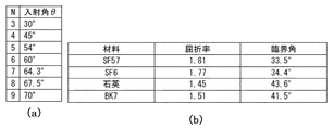
ここで、N角柱の光学ブロック26aの辺の中点で反射する際の入射角θは、θ=90度−180度/Nで表される。図8(a)に、N=9までの入射角の値を表した。つまり、図8(b)の臨界角の値を参照すると、例えば、波長1040nmの光を用いた場合には、入射角が臨界角以上であるという全反射条件を満たすためには、SF57、SF6、石英、BK7の4種類のガラス体において、N≧4、つまり、正四角柱以上の正N角柱であればよいことになる。図7(b)には、SF57において、波長1040nmの光に対して、光路を計算した例を示した。
Here, the incident angle θ at the time of reflection at the midpoint of the side of the N-prism
また、図9(a)には、上記した正六角柱の光学ブロック26aから辺の長さを5%程度変化させた不等辺六角柱を用いて図7(b)と同様に計算した結果を示した。光学ブロック26aの断面の多角形の辺を不等辺にすることで、入光箇所P1からの光路の位置が周回ごとにわずかに変化する。ここでは6周した後に全反射条件を満たさない面に到達し出光箇所P2が与えられる。これによれば、出力ポート28(図6及び7参照)のような特別な形状の加工などを出光箇所P2に与える必要とすることなしに光学ブロック26aから光を出射できる。
FIG. 9 (a) shows the result of calculation similar to FIG. 7 (b) using an unequal side hexagonal column in which the length of the side is changed by about 5% from the regular hexagonal column
また、図9(b)には、不等辺六角柱へのパルス光の入射を直角入射面によって行っている。かかる場合、入力ポート27(図6及び7参照)のような特別な形状の加工を入光箇所P1に与える必要がない。光学ブロック26aの断面の多角形の辺を不等辺にすることで、直線通過経路(光路位置)が周回ごとにわずかに変化し、2周半の後に全反射条件を満たさない面に到達し出光箇所P2が与えられる。これによれば、入力ポート27だけでなく、出力ポート28についても特別な形状の加工などを必要としないのである。
In FIG. 9B, the incidence of the pulsed light on the unequal hexagonal column is performed by the right angle incident surface. In such a case, it is not necessary to apply a specially shaped process like the input port 27 (see FIGS. 6 and 7) to the light incident place P1. By making the polygonal side of the cross section of the
以上のように、光学ブロック26aは正多角柱だけでなく、内部で全反射条件を満たせば、必ずしも、正多角柱である必要はなく、各辺の中点から入力する必要もない。
As described above, the
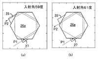
図10は、正六角柱の光学ブロック26aの辺の中点の入光箇所P1において、入射角を変化させたときの光路を示した。図10(a)及び図10(b)は、それぞれ入射角を59度及び61度に変化させたときの光路の計算結果である。光路長は、入射角に対応して連続的に変化する。
FIG. 10 shows the optical path when the incident angle is changed at the light incident point P1 at the midpoint of the side of the regular hexagonal prism
図11には、光路の物理的距離の入射角依存性を示した。なお、光路の物理的距離の値は、正六角柱の光学ブロック26aの辺の長さを100として、これに対する数値(比)で表記した。これから判るように、入光箇所P1に制御ポートを設けて入射角をわずかに変化させることで、圧縮器26が与える分散量を連続的に変化させ得る。かかる分散量調整機構によって、チャープパルス増幅装置1の全体の残留分散量を正確にゼロにすることが可能となる。
FIG. 11 shows the incident angle dependence of the physical distance of the optical path. The value of the physical distance of the optical path is expressed as a numerical value (ratio) with respect to the length of the side of the regular hexagonal
ところで、上記した圧縮器16(26,36,46)において、光学ブロック16a(26a,36a,46a)と逆符号の分散を与える光学材料からなる光学ブロックを用いて、直進通過経路を少なくとも複数与えて光路長の長尺化を行った延伸器12を与えることもできる。かかる延伸器は、上記した圧縮器16(26,36,46)と同様に利点を有し、例えば、分散量調整機構などを与え得る。つまり、これを用いたチャープパルス増幅装置では、全体の残留分散量を正確にゼロにできて、フェムト秒台の短パルス光であっても高い出力で増幅可能でありながら動作安定性により優れるものとできる。
By the way, in the above-described compressor 16 (26, 36, 46), at least a plurality of straight passage paths are provided by using an optical block made of an optical material that gives dispersion opposite to that of the
ここまで本発明による代表的実施例及びこれに基づく改変例について説明したが、本発明は必ずしもこれらに限定されるものではない。当業者であれば、添付した特許請求の範囲を逸脱することなく、種々の代替実施例を見出すことができるだろう。 So far, representative examples and modified examples based on the examples have been described, but the present invention is not necessarily limited thereto. Those skilled in the art will recognize a variety of alternative embodiments without departing from the scope of the appended claims.
1 チャープパルス増幅装置
10 発振器
12 延伸器
12a 回折格子
14 増幅器
14a 利得ファイバ
14b 半導体レーザー
14c ダイクロイックミラー
14d レンズ
16,26,36,46 圧縮器
16a ,26a ,36a,46a 光学ブロック
23 望遠鏡光学系
DESCRIPTION OF SYMBOLS 1
Claims (5)
前記圧縮器は、物質分散を呈する材料からなり正多角形柱のバルク状の光学ブロックを含み、前記光学ブロックには前記パルス光の直進通過経路を少なくとも複数与えるとともに表面における反射を繰り返させて周回させ周回光路を与える一対の入力ポート及び出力ポートが与えられ、前記入力ポートは前記パルス光の入射角を変化させて前記周回光路の物理的距離を変化させて分散量を連続的に変化させて前記出力ポートから出力させて、前記延伸器及び前記増幅器において与えられる残留分散を補償することを特徴とするチャープパルス増幅装置。 A chirped pulse amplifying device that sequentially outputs pulse light from an oscillator through a stretcher, an amplifier, and a compressor, extends the time width of the pulse, amplifies the compressed pulse, and outputs the compressed time width;
The compressor comprises a bulk optical block of Do Ri regular polygonal pillar of a material exhibiting material dispersion, the the optical block was repeated reflections at least a plurality give Rutotomoni surface straight passing path of the pulsed light A pair of input ports and output ports are provided that circulate and provide a circular optical path, and the input port changes the physical distance of the circular optical path by changing the incident angle of the pulsed light to continuously change the amount of dispersion. by output from the output port by said stretcher and chirped pulse amplification system, characterized that you compensate for residual dispersion given in the amplifier.
The stretcher includes a bulky optical block made of a material exhibiting a material dispersion having a sign different from that of the material dispersion of the compressor, and is provided with at least a plurality of straightly passing paths of the pulsed light. A chirped pulse amplification device according to any one of claims 1 to 4 .
Priority Applications (1)
| Application Number | Priority Date | Filing Date | Title |
|---|---|---|---|
| JP2013216504A JP6202316B2 (en) | 2013-10-17 | 2013-10-17 | Chirp pulse amplifier |
Applications Claiming Priority (1)
| Application Number | Priority Date | Filing Date | Title |
|---|---|---|---|
| JP2013216504A JP6202316B2 (en) | 2013-10-17 | 2013-10-17 | Chirp pulse amplifier |
Publications (2)
| Publication Number | Publication Date |
|---|---|
| JP2015079873A JP2015079873A (en) | 2015-04-23 |
| JP6202316B2 true JP6202316B2 (en) | 2017-09-27 |
Family
ID=53011065
Family Applications (1)
| Application Number | Title | Priority Date | Filing Date |
|---|---|---|---|
| JP2013216504A Active JP6202316B2 (en) | 2013-10-17 | 2013-10-17 | Chirp pulse amplifier |
Country Status (1)
| Country | Link |
|---|---|
| JP (1) | JP6202316B2 (en) |
Families Citing this family (1)
| Publication number | Priority date | Publication date | Assignee | Title |
|---|---|---|---|---|
| JP7569564B2 (en) | 2019-09-19 | 2024-10-18 | 大学共同利用機関法人自然科学研究機構 | Laser device and pulse width changing method |
Family Cites Families (8)
| Publication number | Priority date | Publication date | Assignee | Title |
|---|---|---|---|---|
| US6272156B1 (en) * | 1998-01-28 | 2001-08-07 | Coherent, Inc. | Apparatus for ultrashort pulse transportation and delivery |
| US7257302B2 (en) * | 2003-06-03 | 2007-08-14 | Imra America, Inc. | In-line, high energy fiber chirped pulse amplification system |
| DE502004008293D1 (en) * | 2003-11-28 | 2008-11-27 | High Q Laser Production Gmbh | HIGH-REPAIRING LASER SYSTEM WITH COMPACT CONSTRUCTION |
| JP3987554B2 (en) * | 2005-11-03 | 2007-10-10 | 光州科学技術院 | High repetition rate femtosecond playback amplifier |
| JP5177969B2 (en) * | 2006-07-12 | 2013-04-10 | 浜松ホトニクス株式会社 | Optical amplifier |
| JP5384307B2 (en) * | 2009-11-30 | 2014-01-08 | 浜松ホトニクス株式会社 | Laser equipment |
| US8908739B2 (en) * | 2011-12-23 | 2014-12-09 | Alcon Lensx, Inc. | Transverse adjustable laser beam restrictor |
| JP5524381B2 (en) * | 2013-03-29 | 2014-06-18 | 浜松ホトニクス株式会社 | Pulse width converter and optical amplification system |
-
2013
- 2013-10-17 JP JP2013216504A patent/JP6202316B2/en active Active
Also Published As
| Publication number | Publication date |
|---|---|
| JP2015079873A (en) | 2015-04-23 |
Similar Documents
| Publication | Publication Date | Title |
|---|---|---|
| EP2944003B1 (en) | System and method for high-intensity ultrashort pulse compression | |
| US9564729B2 (en) | Device for emitting super-continuous wide-band light and uses thereof | |
| US20150063380A1 (en) | Method and Apparatus for Generating Ultrafast, High Energy, High Power Laser Pulses | |
| US20110122903A1 (en) | Wide-Band Wavelength-Variable Laser Device | |
| US10216063B2 (en) | Single pass laser amplifier with pulsed pumping | |
| US6667999B2 (en) | Cooling of high power laser systems | |
| TWI474060B (en) | Supercontinuum generation system | |
| US8199397B2 (en) | Negative dispersion mirror and mode-locked solid-state laser apparatus including the mirror | |
| JP5319989B2 (en) | Mode-locked solid-state laser device | |
| CN104201553A (en) | Dual-wavelength tunable solid laser and application thereof | |
| JP2020127000A (en) | Passive Q-switched solid-state laser with compressed pulse width | |
| JP6202316B2 (en) | Chirp pulse amplifier | |
| WO2015103667A1 (en) | A method and a system for converting an input light into an output light beam | |
| Kim et al. | Femtosecond laser based on Yb: KYW crystals with suppression of spectral narrowing in a regenerative amplifier by spectral profiling of the pulse | |
| CN104600554B (en) | Broadband high-efficiency laser amplification device | |
| Šulc et al. | Diode pumped tunable lasers based on Tm: CaF2 and Tm: Ho: CaF2 ceramics | |
| JP2019532333A (en) | Cascaded long pulse continuous wave Raman laser | |
| Le Blanc et al. | Toward a terawatt-kilohertz repetition-rate laser | |
| Brooks et al. | High peak power operation and harmonic generation of a single-polarization, Yb-doped photonic crystal fiber amplifier | |
| Petrov et al. | Pump channel of parametric amplifier of terawatt femtosecond Yb laser system | |
| RU2427062C2 (en) | Tunable frequency selector | |
| Zhao et al. | High-efficiency Nd: YAG 1061 nm, 1064 nm dual wavelength laser at room temperature operation | |
| Kiselev et al. | Experimental study of laser beam fluence fluctuation smoothing in asymmetric | |
| Sickinger | Development of a Thulium Germanate Thin Disk Laser Prototype | |
| JP6341596B2 (en) | Laser equipment |
Legal Events
| Date | Code | Title | Description |
|---|---|---|---|
| A621 | Written request for application examination |
Free format text: JAPANESE INTERMEDIATE CODE: A621 Effective date: 20160729 |
|
| A977 | Report on retrieval |
Free format text: JAPANESE INTERMEDIATE CODE: A971007 Effective date: 20170419 |
|
| A131 | Notification of reasons for refusal |
Free format text: JAPANESE INTERMEDIATE CODE: A131 Effective date: 20170425 |
|
| A521 | Request for written amendment filed |
Free format text: JAPANESE INTERMEDIATE CODE: A523 Effective date: 20170622 |
|
| TRDD | Decision of grant or rejection written | ||
| A01 | Written decision to grant a patent or to grant a registration (utility model) |
Free format text: JAPANESE INTERMEDIATE CODE: A01 Effective date: 20170815 |
|
| A61 | First payment of annual fees (during grant procedure) |
Free format text: JAPANESE INTERMEDIATE CODE: A61 Effective date: 20170816 |
|
| R150 | Certificate of patent or registration of utility model |
Ref document number: 6202316 Country of ref document: JP Free format text: JAPANESE INTERMEDIATE CODE: R150 |
|
| R250 | Receipt of annual fees |
Free format text: JAPANESE INTERMEDIATE CODE: R250 |
|
| R250 | Receipt of annual fees |
Free format text: JAPANESE INTERMEDIATE CODE: R250 |
|
| R250 | Receipt of annual fees |
Free format text: JAPANESE INTERMEDIATE CODE: R250 |
|
| R250 | Receipt of annual fees |
Free format text: JAPANESE INTERMEDIATE CODE: R250 |
|
| R250 | Receipt of annual fees |
Free format text: JAPANESE INTERMEDIATE CODE: R250 |