JP6197346B2 - Linear motor - Google Patents
Linear motor Download PDFInfo
- Publication number
- JP6197346B2 JP6197346B2 JP2013089728A JP2013089728A JP6197346B2 JP 6197346 B2 JP6197346 B2 JP 6197346B2 JP 2013089728 A JP2013089728 A JP 2013089728A JP 2013089728 A JP2013089728 A JP 2013089728A JP 6197346 B2 JP6197346 B2 JP 6197346B2
- Authority
- JP
- Japan
- Prior art keywords
- linear motor
- plate
- magnets
- mover
- moving direction
- Prior art date
- Legal status (The legal status is an assumption and is not a legal conclusion. Google has not performed a legal analysis and makes no representation as to the accuracy of the status listed.)
- Active
Links
- 239000000463 material Substances 0.000 claims description 9
- 238000004804 winding Methods 0.000 claims description 8
- 239000000696 magnetic material Substances 0.000 claims description 7
- 230000005415 magnetization Effects 0.000 claims description 6
- 229910000859 α-Fe Inorganic materials 0.000 claims description 5
- 230000004907 flux Effects 0.000 description 31
- 230000000694 effects Effects 0.000 description 17
- 230000000052 comparative effect Effects 0.000 description 14
- 239000011295 pitch Substances 0.000 description 8
- 238000010586 diagram Methods 0.000 description 7
- 239000012811 non-conductive material Substances 0.000 description 6
- 229920006395 saturated elastomer Polymers 0.000 description 6
- 229910000831 Steel Inorganic materials 0.000 description 4
- 230000007246 mechanism Effects 0.000 description 4
- 239000010959 steel Substances 0.000 description 4
- 238000003466 welding Methods 0.000 description 4
- 238000006243 chemical reaction Methods 0.000 description 3
- 229910001172 neodymium magnet Inorganic materials 0.000 description 3
- 229910052782 aluminium Inorganic materials 0.000 description 2
- XAGFODPZIPBFFR-UHFFFAOYSA-N aluminium Chemical compound [Al] XAGFODPZIPBFFR-UHFFFAOYSA-N 0.000 description 2
- 238000005452 bending Methods 0.000 description 2
- 230000015572 biosynthetic process Effects 0.000 description 2
- 239000000919 ceramic Substances 0.000 description 2
- 238000005304 joining Methods 0.000 description 2
- 238000004519 manufacturing process Methods 0.000 description 2
- 229910052751 metal Inorganic materials 0.000 description 2
- 239000002184 metal Substances 0.000 description 2
- 230000002093 peripheral effect Effects 0.000 description 2
- 230000001141 propulsive effect Effects 0.000 description 2
- 230000010349 pulsation Effects 0.000 description 2
- 238000004904 shortening Methods 0.000 description 2
- 229910001220 stainless steel Inorganic materials 0.000 description 2
- 239000010935 stainless steel Substances 0.000 description 2
- 238000003786 synthesis reaction Methods 0.000 description 2
- ZOXJGFHDIHLPTG-UHFFFAOYSA-N Boron Chemical compound [B] ZOXJGFHDIHLPTG-UHFFFAOYSA-N 0.000 description 1
- 229910001369 Brass Inorganic materials 0.000 description 1
- RYGMFSIKBFXOCR-UHFFFAOYSA-N Copper Chemical compound [Cu] RYGMFSIKBFXOCR-UHFFFAOYSA-N 0.000 description 1
- XEEYBQQBJWHFJM-UHFFFAOYSA-N Iron Chemical compound [Fe] XEEYBQQBJWHFJM-UHFFFAOYSA-N 0.000 description 1
- 229910052779 Neodymium Inorganic materials 0.000 description 1
- 239000004952 Polyamide Substances 0.000 description 1
- 229910000828 alnico Inorganic materials 0.000 description 1
- 229910052796 boron Inorganic materials 0.000 description 1
- 239000010951 brass Substances 0.000 description 1
- 230000008859 change Effects 0.000 description 1
- 239000002131 composite material Substances 0.000 description 1
- 229910052802 copper Inorganic materials 0.000 description 1
- 239000010949 copper Substances 0.000 description 1
- 238000009826 distribution Methods 0.000 description 1
- 229920006351 engineering plastic Polymers 0.000 description 1
- 230000005284 excitation Effects 0.000 description 1
- 230000006872 improvement Effects 0.000 description 1
- 238000010030 laminating Methods 0.000 description 1
- 239000004973 liquid crystal related substance Substances 0.000 description 1
- 230000004048 modification Effects 0.000 description 1
- 238000012986 modification Methods 0.000 description 1
- QEFYFXOXNSNQGX-UHFFFAOYSA-N neodymium atom Chemical compound [Nd] QEFYFXOXNSNQGX-UHFFFAOYSA-N 0.000 description 1
- 239000000615 nonconductor Substances 0.000 description 1
- 230000035699 permeability Effects 0.000 description 1
- 229920002647 polyamide Polymers 0.000 description 1
- 239000004417 polycarbonate Substances 0.000 description 1
- 229920000515 polycarbonate Polymers 0.000 description 1
- 229910000938 samarium–cobalt magnet Inorganic materials 0.000 description 1
- 239000004065 semiconductor Substances 0.000 description 1
- 239000000758 substrate Substances 0.000 description 1
Images


Landscapes
- Linear Motors (AREA)
- Engineering & Computer Science (AREA)
- Physics & Mathematics (AREA)
- Chemical & Material Sciences (AREA)
- Combustion & Propulsion (AREA)
- Electromagnetism (AREA)
- Power Engineering (AREA)
Description
本発明は固定子と、コイル及び磁石を有する可動子とを組み合わせてなるリニアモータに関する。 The present invention relates to a linear motor formed by combining a stator and a mover having a coil and a magnet.
例えば、半導体製造装置、液晶表示装置の製造分野においては、大面積の基板等の処理対象物を高速度にて直線移動させ、適宜の移動位置にて高精度に位置決めすることができる送り装置が必要である。この種の送り装置は、一般的には、駆動源としてのモータの回転運動をボールねじ機構等の運動変換機構により直線運動に変換して実現されるが、運動変換機構が介在することから、移動速度の高速化に限界がある。また運動変換機構の機械的な誤差の存在により、位置決め精度も不十分であるという問題がある。 For example, in the field of manufacturing semiconductor manufacturing devices and liquid crystal display devices, there is a feeding device that can linearly move an object to be processed such as a large-area substrate at a high speed and accurately position the object at an appropriate moving position. is necessary. This type of feeding device is generally realized by converting the rotational motion of a motor as a drive source into a linear motion by a motion conversion mechanism such as a ball screw mechanism, but since a motion conversion mechanism is interposed, There is a limit to increasing the moving speed. There is also a problem that positioning accuracy is insufficient due to the presence of mechanical errors in the motion conversion mechanism.
この問題に対応するため、近年においては、直線運動出力が直接的に取り出し可能なリニアモータを駆動源とする送り装置が使用されている。リニアモータは、直線状の固定子と該固定子に沿って移動する可動子とを備えている。前述した送り装置においては、板状の永久磁石を一定間隔毎に多数並設して固定子を構成し、磁極歯と通電コイルとを備える電機子を可動子としたムービングコイル型のリニアモータ(例えば、特許文献1参照)が使用されている。 In order to cope with this problem, in recent years, a feeding device using a linear motor capable of directly taking out a linear motion output as a drive source has been used. The linear motor includes a linear stator and a mover that moves along the stator. In the above-described feeding device, a moving coil type linear motor (a moving coil type linear motor) in which a large number of plate-like permanent magnets are arranged in parallel at regular intervals to constitute a stator, and an armature having magnetic pole teeth and energizing coils is used as a mover. For example, Patent Document 1) is used.
ムービングコイル型のリニアモータでは、固定子に磁石を配置するため、リニアモータの全長が長くなるほど(可動子の移動距離が長くなるほど)、使用する磁石の量が増える。近年、希土類の価格上昇に伴い、使用する磁石量の増加は、コスト増加の原因となっていた。
また、推力を増大させるためにはコイルの巻数を増やすことが必要であるが、巻枠の移動方向の寸法を増やすと、可動子の全体の移動方向の寸法が増加する。可動子の移動方向の寸法増加は、可動子の有効移動可能距離の低下を招いていた。
一方、可動子の移動方向の寸法を短くしながら大推力を得ようとすると、固定子と磁束のやり取りを行う電機子ヨークが磁気飽和を起こしやすくなる。
In a moving coil type linear motor, since magnets are arranged on the stator, the amount of magnets to be used increases as the total length of the linear motor increases (the moving distance of the mover increases). In recent years, with the increase in the price of rare earths, an increase in the amount of magnets used has caused an increase in cost.
Further, in order to increase the thrust, it is necessary to increase the number of turns of the coil. However, when the dimension in the moving direction of the winding frame is increased, the dimension in the entire moving direction of the mover increases. An increase in dimension in the moving direction of the mover has caused a decrease in the effective movable distance of the mover.
On the other hand, if an attempt is made to obtain a large thrust while shortening the dimension of the mover in the moving direction, the armature yoke that exchanges magnetic flux with the stator tends to cause magnetic saturation.
本発明は上述のごとき事情に鑑みてなされたものであり、リニアモータの全長が長くても磁石の使用量が増加せず、電機子ヨークが磁気飽和を起こしにくい構造により小型化及び軽量化した可動子を備えるリニアモータを提供することを目的とする。 The present invention has been made in view of the circumstances as described above, and the amount of magnets used does not increase even if the total length of the linear motor is long, and the armature yoke is reduced in size and weight by a structure that hardly causes magnetic saturation. It aims at providing a linear motor provided with a mover.
本発明に係るリニアモータは、固定子、及びコイルを有する可動子を備えたリニアモータにおいて、前記固定子は前記可動子の移動方向に長い2つの板状部を有し、2つの板状部は可動子の移動域を間にして、磁気的に結合するように対設してあり、前記2つの板状部の対向面それぞれには、複数の歯部が、一方の板状部の歯部と他方の板状部の歯部とで千鳥状になるように前記移動方向に並設してあり、前記可動子は前記コイル内部に、複数個の磁石を1組とする2組の組磁石及び3個のヨークが交互に前記移動方向に沿って配列してあり、前記各組磁石を構成する複数個の磁石は前記移動方向に同じ向きで磁化され、前記板状部の対向方向に距離を隔てて配してあり、2組の前記組磁石の磁化方向は対向してあり、前記ヨークの前記歯部と対向する面と前記組磁石の前記歯部と対向する面とは略面一となっていることを特徴とする。 The linear motor according to the present invention is a linear motor including a stator and a mover having a coil. The stator has two plate-like portions that are long in the moving direction of the mover. Are arranged so as to be magnetically coupled with the moving area of the mover in between, and a plurality of tooth portions are provided on each of the opposing surfaces of the two plate-like portions. And the teeth of the other plate-shaped part are arranged in the moving direction so as to form a staggered pattern, and the mover has two sets of magnets inside the coil. Magnets and three yokes are alternately arranged along the moving direction, and the plurality of magnets constituting each pair of magnets are magnetized in the same direction in the moving direction, and in the opposite direction of the plate-like portion. Yes and arranged at a distance, the magnetization directions of the two sets of the set magnets Yes to face, the teeth of the yoke Characterized in that it is substantially flush to the opposite surface and the teeth and the opposing surfaces of the pair magnet.
本発明にあっては、板状の磁石からなる組磁石2組、板状のヨーク3つを縦姿勢に配列し可動子に備えるという最小構成であり、かつ、コイルの巻数を稼ぐことができるので、可動子の移動方向の寸法を小さく、最低限の推進力を確保することが可能となる。また、固定子には磁石を使用しないので、リニアモータの全長が長い場合であっても磁石の使用量が増加しない。 In the present invention, it is a minimum configuration in which two pairs of magnets composed of plate-like magnets and three plate-like yokes are arranged in a vertical posture and provided in the mover, and the number of turns of the coil can be increased. As a result, the dimension of the mover in the moving direction can be reduced, and a minimum propulsive force can be secured. In addition, since no magnet is used for the stator, the amount of magnet used does not increase even when the total length of the linear motor is long.
本発明に係るリニアモータは、前記各組磁石を構成する複数の磁石は前記板状部の対向方向に非磁性体を間にして配してあることを特徴とする。 The linear motor according to the present invention is characterized in that a plurality of magnets constituting each pair of magnets are arranged with a non-magnetic material in the opposing direction of the plate-like portion.
本発明にあっては、組磁石に占める磁石の体積を減らし、ヨークに流れる磁束量を抑制することにより、ヨークの磁気飽和を抑制し、推力リニアリティを確保している。 In the present invention, the volume of the magnet in the assembled magnet is reduced, and the amount of magnetic flux flowing through the yoke is suppressed, thereby suppressing the magnetic saturation of the yoke and ensuring the thrust linearity.
本発明に係るリニアモータは、前記非磁性体は空隙であることを特徴とする。 The linear motor according to the present invention is characterized in that the nonmagnetic material is a gap.
本発明にあっては、非磁性体は空隙であるので、可動子を軽量にすることが可能となる。 In the present invention, since the nonmagnetic material is a gap, the mover can be reduced in weight.
本発明に係るリニアモータは、前記各組磁石を構成する複数個の磁石は前記板状部の対向方向にフェライト磁石を間にして配してあることを特徴とする。 The linear motor according to the present invention is characterized in that a plurality of magnets constituting each set of magnets are arranged with ferrite magnets in the direction opposite to the plate-like portion.
本発明にあっては、組磁石を構成する磁石の間に磁力が比較的小さいフェライト磁石を設けることにより、組磁石全体の磁力を抑えつつ、組磁石の強度を確保すると共に、組立性の確保が可能となる。 In the present invention, by providing a ferrite magnet having a relatively small magnetic force between the magnets constituting the assembled magnet, the strength of the assembled magnet is ensured while the magnetic force of the entire assembled magnet is suppressed, and the assembling property is ensured. Is possible.
本発明に係るリニアモータは、前記各組磁石は2個の磁石から構成されていることを特徴とする。 The linear motor according to the present invention is characterized in that each set magnet is composed of two magnets.
本発明にあっては、各組磁石は2個の磁石から構成しているので、部品点数の増加を最小限することが可能となる。 In the present invention, since each set magnet is composed of two magnets, an increase in the number of parts can be minimized.
本発明に係るリニアモータは、前記各組磁石及び各ヨークそれぞれの前記板状部の対向方向の高さは、前記それぞれの移動方向の幅の2倍から4倍であることを特徴とする。 The linear motor according to the present invention is characterized in that the height in the opposing direction of the plate-like portion of each of the magnet pairs and each yoke is two to four times the width in the respective moving direction.
本発明にあっては、各組磁石及び各ヨークのそれぞれの板状部の対向方向の高さは、移動方向の幅の2倍から4倍としたので、固定子の移動方向の寸法を増加させること無く、コイルの巻枠を確保することが可能となる。 In the present invention, the height in the opposing direction of each plate-like portion of each assembled magnet and each yoke is set to be 2 to 4 times the width in the moving direction, so the dimension in the moving direction of the stator is increased. Without making it possible, it is possible to secure a coil winding frame.
本発明に係るリニアモータは、前記2組の組磁石に挟まれているヨークが他の2つのヨークより前記移動方向に長いことを特徴とする。 The linear motor according to the present invention is characterized in that a yoke sandwiched between the two sets of magnets is longer in the moving direction than the other two yokes.
本発明にあっては、2組の組磁石に挟まれているヨークは、1組の磁石としか接しない他の2つのヨークより移動方向に長くしてある。磁石とやり取りする磁束量に合わせて移動方向の長さ、すなわち歯部と対向する部分の長さを定めているので、コイルに流す電流量が増加しても、ヨークが磁気飽和しにくくなる。 In the present invention, the yoke sandwiched between the two sets of magnets is longer in the moving direction than the other two yokes that are in contact with only one set of magnets. Since the length in the moving direction, that is, the length of the portion facing the tooth portion is determined according to the amount of magnetic flux exchanged with the magnet, the yoke is less likely to be magnetically saturated even if the amount of current flowing through the coil is increased.
本発明に係るリニアモータは、前記2組の組磁石に挟まれているヨークの前記移動方向の長さは、他の2つのヨークの2倍の長さであることを特徴とする。 In the linear motor according to the present invention, the length of the yoke sandwiched between the two sets of magnets in the moving direction is twice as long as the other two yokes.
本発明にあっては、2組の組磁石に挟まれているヨークの移動方向の長さは、流れる磁束量に最適な他の2つのヨークの2倍の長さとしてあるので、可動子の移動方向の長さを小さくしながら、ヨークの磁気飽和を緩和して大推力のリニアモータを得ることが可能となる。 In the present invention, the length in the moving direction of the yoke sandwiched between the two sets of magnets is twice as long as the other two yokes that are optimal for the amount of magnetic flux flowing. While reducing the length in the moving direction, it is possible to relax the magnetic saturation of the yoke and obtain a large thrust linear motor.
本発明に係るリニアモータは、前記歯部の並設方向の幅が、歯部の並設間隔よりも長いことを特徴とする。 The linear motor according to the present invention is characterized in that the width of the tooth portions in the juxtaposed direction is longer than the interval between the tooth portions.
本発明にあっては、歯部の並設方向の幅が歯部の並設間隔よりも広くしてあるので、より大きな推力を得ることが可能となる。 In the present invention, since the width of the tooth portions in the direction in which the teeth are arranged is wider than the interval between the teeth, the larger thrust can be obtained.
本発明に係るリニアモータは、前記各組磁石を構成する複数個の磁石及び3つのヨークが直方体状をなし、各磁石及び各ヨークの前記移動方向側の面は、前記移動方向及び前記板状部の対向方向と直交する方向に対して傾斜していることを特徴とする。 In the linear motor according to the present invention, the plurality of magnets and the three yokes constituting each pair of magnets form a rectangular parallelepiped shape, and the surfaces of the magnets and the yokes on the moving direction side are the moving direction and the plate-like shape. It is inclined with respect to the direction orthogonal to the opposing direction of the part.
本発明にあっては、各組磁石及び各ヨークの前記移動方向側の面は、前記移動方向及び前記板状部の対向方向と直交する方向に対して傾斜している。すなわち所謂スキュー配置としてあるので、ディテント力が低減され、固定子と可動子の相対位置の違いによる推力むらを低減することが可能となる。 In the present invention, the surfaces on the moving direction side of each assembled magnet and each yoke are inclined with respect to the direction orthogonal to the moving direction and the opposing direction of the plate-like portion. In other words, since it is a so-called skew arrangement, the detent force is reduced, and it is possible to reduce the thrust unevenness due to the difference in the relative positions of the stator and the mover.
本発明に係るリニアモータは、前記歯部が直方体状をなし、前記歯部の前記板状部に平行な断面の向かい合う2つの短辺は前記移動方向及び前記板状部の対向方向と直交する方向に対し傾斜していることを特徴とする。 In the linear motor according to the present invention, the tooth portion has a rectangular parallelepiped shape, and two short sides facing each other in a cross section parallel to the plate-like portion of the tooth portion are orthogonal to the moving direction and the opposing direction of the plate-like portion. Inclined with respect to the direction.
本発明にあっては、前記歯部が直方体状をなし、前記歯部の前記板状部に平行な断面の向かい合う2つの短辺は前記移動方向及び前記板状部の対向方向と直交する方向に対し傾斜している。すなわち歯部をスキュー配置としてあるので、ディテント力が低減され、固定子と可動子の相対位置の違いによる推力むらを低減することが可能となる。 In the present invention, the tooth portion has a rectangular parallelepiped shape, and two short sides facing each other in a cross section parallel to the plate-like portion of the tooth portion are perpendicular to the moving direction and the opposing direction of the plate-like portion. It is inclined to. That is, since the tooth portions are arranged in a skew manner, the detent force is reduced, and it becomes possible to reduce the thrust unevenness due to the difference in the relative positions of the stator and the mover.
本発明に係るリニアモータは、前記2つの板状部が有する歯部は、前記2つの短辺の傾斜方向が互いに逆であることを特徴とする。 Linear motor according to the present invention, the tooth portion to which the two plate-shaped portion has is characterized by tilting direction before Symbol two short sides are opposite to each other.
本発明にあっては、前記2つの板状部が有する歯部は、前記2つの短辺の傾斜方向が互いに逆としてある。すなわち歯部を傾ける方向を板状部の一方と他方とで異なるようにしているので、可動子が移動方向に対して左右に傾くことにより生じるこじりを抑えることが可能となる。 In the present invention, the tooth portion to which the two plate-like portion having the inclination direction before Symbol two short sides is as opposite to each other. That is, since the direction in which the tooth portion is inclined is different between one and the other of the plate-like portions, it is possible to suppress the twisting that occurs when the mover is inclined to the left and right with respect to the moving direction.
本発明に係るリニアモータは、前記ヨーク及び組磁石の前記移動方向に平行な側面と前記コイルとの間に設けられた板状の非磁性体板と、該非磁性体板と前記ヨーク及び組磁石を介して対向しかつ前記コイルとの間に設けられた板状の非磁性非導電性材からなる補助板を備えることを特徴とする。 The linear motor according to the present invention includes a plate-like nonmagnetic plate provided between a side surface parallel to the moving direction of the yoke and the assembled magnet and the coil, the nonmagnetic plate, the yoke, and the assembled magnet. And an auxiliary plate made of a plate-like nonmagnetic nonconductive material provided between the coil and the coil.
本発明にあっては、ヨークとコイルとの間に非磁性非導電性材を設けたので、ヨークに流れる渦電流の流路が部分的に遮断され、渦電流損を小さくすることが可能となる。 In the present invention, since the non-magnetic non-conductive material is provided between the yoke and the coil, the flow path of the eddy current flowing through the yoke is partially blocked, and the eddy current loss can be reduced. Become.
本発明に係るリニアモータは、前記非磁性体板に連結され、前記移動方向に配列される3つの可動子を連結する連結部をさらに備えることを特徴とする。 The linear motor according to the present invention may further include a connecting portion that is connected to the nonmagnetic plate and connects three movers arranged in the moving direction.
本発明にあっては、3つの可動子を備えているので、可動子が一つの場合に比べてより大きな推力を得ることが可能となる。 In the present invention, since the three movable elements are provided, it is possible to obtain a larger thrust than in the case where there is one movable element.
本発明に係るリニアモータは、前記非磁性体板は、前記コイルの巻線を間にして対向する板状の第1突出板部及び第2突出板部と、前記第1突出板部及び前記第2突出板部を結ぶ基部を有することを特徴とする。 In the linear motor according to the present invention, the non-magnetic plate includes plate-like first protruding plate portions and second protruding plate portions facing each other with the coil winding interposed therebetween, the first protruding plate portion, and the It has the base which connects a 2nd protrusion board part, It is characterized by the above-mentioned.
本発明にあっては、コイルの外部に設けられた第2突出板部を備えているので、リニアモータの推力を容易に外部へ伝達することが可能となる。 In the present invention, since the second projecting plate portion provided outside the coil is provided, the thrust of the linear motor can be easily transmitted to the outside.
本発明にあっては、板状の磁石からなる組磁石を2組、板状のヨーク3つを縦姿勢に配列し可動子に備えるという最小構成であり、かつ、コイルの巻数を稼ぐことができるので、可動子の移動方向の寸法を小さく、最低限の推進力を確保することが可能となる。また、固定子には磁石を使用しないので、リニアモータの全長が長い場合であっても磁石の使用量が増加しないという効果を奏する。
ここで本明細書及び請求項で使用する電機子ヨークとヨークとは同じ意味として使用する。
In the present invention, it is a minimum configuration in which two sets of magnets composed of plate-like magnets, three plate-like yokes are arranged in a vertical posture and provided in the mover, and the number of turns of the coil can be increased. As a result, the dimension of the mover in the moving direction can be reduced, and a minimum propulsive force can be secured. In addition, since no magnet is used for the stator, there is an effect that the amount of magnet used does not increase even when the linear motor has a long overall length.
Here, the armature yoke and the yoke used in the present specification and claims are used interchangeably.
実施の形態1
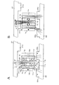
図1は実施の形態1に係るリニアモータの概略構成の一例を示す部分破断斜視図である。図2は実施の形態1に係るリニアモータの可動子1の構成例を示す平面図である。図3は実施の形態1に係るリニアモータの概略構成を示す断面図である。図4は図2のIV−IV線による断面図である。図5は実施の形態1に係るリニアモータの概略構成を示す側面図である。
FIG. 1 is a partially broken perspective view showing an example of a schematic configuration of the linear motor according to the first embodiment. FIG. 2 is a plan view showing a configuration example of the
本実施の形態に係るリニアモータは可動子1と固定子2とを含む。可動子1はそれぞれ板状をなす電機子ヨーク1b、組磁石1c、1dを縦姿勢で並べて連結させたものに、コイル1aを巻回した構成をなしている。電機子ヨーク1b、組磁石1c、1dを構成する磁石は板状をなしている。本実施の形態において、可動子1は電機子ヨーク1bを3つ、組磁石1c、1dを各1組備える最小構成としてある。図1又は図2に示すように電機子ヨーク1b、組磁石1c、電機子ヨーク1b、組磁石1d、電機子ヨーク1bと、電機子ヨーク1bと組磁石1c又は1dは可動子1の移動方向に沿って交互に縦姿勢で配列されている。組磁石1c及び組磁石1dは中央の電機子ヨーク1bを挟むように配置されている。図2、図5に示す白抜き矢印は各組磁石1c、1dを構成する各磁石の磁化方向を示している。白抜矢印の終点はN極、始点はS極を示す。組磁石1c及び組磁石1dは可動子1の移動方向に沿って磁化してあり、磁化方向が互いに対向している。以上のように配置された電機子ヨーク1b、組磁石1c又は1dをコイル1aが囲繞している。
The linear motor according to the present embodiment includes a
本実施の形態において、電機子ヨーク1bの移動方向の幅w1は組磁石1cの幅w2よりも短くしてある(図5参照)。電機子ヨーク1bは上板部21と下板部22との対向方向(図5の上下方向)の高さh1が、移動方向(図5の左右方向)の幅w1の2から4倍としてある。同様に組磁石1cは上板部21と下板部22との対向方向の高さh2が、移動方向の幅w2の2から4倍としてある。組磁石1dは組磁石1cと同一である。これは可動子1の移動方向の長さをなるべく短くしつつ、コイル1aの巻線数を確保するためである。リニアモータにおいて、可動子1の移動方向の長さは有効可動域に影響を与える。可動子1の移動方向の長さが長いほど、固定子2の長手方向における可動子1の有効可動域が短くなるからである。そこで、本実施の形態においては、可動子1の図5における高さ方向の寸法を移動方向に対して長くすることでコイル1aの巻線数を確保するとともに、移動方向の長さを短くすることを実現している。
比較例h1(h2)/w1(w2)の値が2倍未満ではコイル1aの巻線数を確保することが困難となる。また4倍超では可動子の重量が大きくなり巻線数の上昇に比して推力が大きくならない。
In the present embodiment, the width w1 of the
If the value of Comparative Example h1 (h2) / w1 (w2) is less than twice, it is difficult to ensure the number of turns of the
図3に示すように、固定子2は断面コの字状(U字状)である。固定子2は2つの板状部、上板部21、下板部22を含む。上板部21と下板部22とは可動子1の移動域を間にして、互いに板面が対向している。板状をなす側板部23は上板部21と下板部22を結合している。図1に示すように、固定子2は可動子1の移動方向に長くなっている。上板部21は下板部22と対向する一面に複数の歯部21aを備えている。歯部21aは可動子1の移動方向に沿って上板部21に並置してある。下板部22は上板部21に対向する面に複数の歯部22aを備えている。歯部22aは可動子1の移動方向に沿って下板部22に並置してある。歯部21a、歯部22aはそれぞれ略直方体状をなしている。固定子2は軟磁性金属、例えば平板状の圧延鋼材を折り曲げることにより形成する。固定子2は折り曲げにより形成する他に平板状の圧延鋼材を溶接等の接合やねじ止め等により固定して形成しても良い。固定子2の上板部21と下板部22とは側板部23により磁気的に結合してある。歯部21a、歯部22aについても、それぞれ軟磁性金属板、例えば鋼板等を積層して直方体状に形成する。直方体状に形成した歯部21a、歯部22aはそれぞれ、上板部21、下板部22に溶接等による接合又はねじ止め等により固定する。
また略コの字に形成した磁性鋼板の歯部となる部位を残し歯部となる部位の両側に溝を掘り込み加工により形成し、歯部21a、歯部22aとしても良い。このようにすると、歯部を溶接等で接合又はねじ止め等により固定する場合に比べて、固定子2のコストダウンが可能となる。さらにまた、板状部材で歯部21a、歯部22aとなる部分を残しスリットを形成しても良い。または歯部21a、歯部22aとなる部分をくし歯状に形成したりしても良い。歯部21a、22aの形状は直方体状としたが、それに限られない。電機子ヨーク1bと磁束のやり取りが行えるのであれば、歯部21a、22aを直方体状以外の形状としても良い。例えば半円柱状、台形柱状でも良い。なお、図3に示す向きで設置されることが固定子2の必須の要件ではない。設置可能な如何なる向きで使用することも可能である。上板部21が下側や左右側となるように設置しても良い。
As shown in FIG. 3, the
Alternatively, a
図4に示すように組磁石1cは2個の永久磁石(磁石)10c、11cを含む。永久磁石10c、11cは上板部21及び下板部22の対向方向に沿って、空隙(非磁性体)12cを間にして、距離を隔てて配されている。組磁石1dは2個の永久磁石(磁石)10d、11dを含む。永久磁石10d、11dは上板部21及び下板部22の対向方向に沿って、空隙(非磁性体)12dを間にして、配されている。図4に示す例において、永久磁石10c、10dは上板部21、歯部21aに対向しており、永久磁石11c、11dは下板部22、歯部22aに対向している。図4においては記載を省略しているが、組磁石1cを構成する永久磁石10c、11cは可動子1の移動方向(紙面左右方向)に沿って同じ方向に磁化してある。組磁石1dを構成する永久磁石10d、11dは可動子1の移動方向に沿って同じ方向に磁化してある。永久磁石10cと永久磁石10dとは互いに対向する向きに磁化してある。同様に永久磁石11cと永久磁石11dとは互いに対向する向きに磁化してある。したがって組磁石1cと組磁石1dは互いに対向する向きに磁化されている。組磁石1c、1dは2つの電機子コア1bに挟まれている構造となっている。図1及び図3に示すように、電機子ヨーク1b、組磁石1c及び1dは、2つの板部(上板部21及び下板部22)の対向する面の法線方向の長さ(図3の紙面上下方向の長さ)を略同一としてある。電機子ヨーク1b、組磁石1c及び1dは、歯部21a又は歯部22aと対向する面が略面一となっている。
組磁石1c、1dを構成する永久磁石10c、11c、10d、11dはネオジム(Nd)、鉄(Fe)、ボロン(B)を主成分とするネオジム磁石である。ネオジム磁石に限らず、アルニコ磁石、フェライト磁石、サマリウムコバルト磁石などを用いても良い。
なお、組磁石1c、1dはそれぞれ2個の永久磁石10c及び11c並びに永久磁石10d及び11dからなるものとしたが、各組磁石を構成する永久磁石は3個以上としても
良い。
As shown in FIG. 4, the assembled
The
The assembled
図3及び図5に示すように、歯部21a及び歯部22aは同一形状、同一寸法であることが望ましい。本実施の形態に係るリニアモータは可動子1が備える電機子ヨーク1bが3個という最小構成である。
As shown in FIGS. 3 and 5, it is desirable that the
図6、図7及び図8は実施の形態1に係るリニアモータの推力発生原理を説明するための図である。可動子1の移動方向に沿う部分は説明の都合上、省略して移動方向と直交する部分の断面のみ表示してある。可動子1のコイル1aに交流電流を流す。図6、7のコイル1aに示す黒丸印は紙面の裏から表への通電、バツ印は紙面の表から裏への通電を表している(交流電流を流した際のある時点の電流の向きを示した)。コイル1aの通電により、図6に点線で示したような磁束の流れが発生する。
6, 7 and 8 are diagrams for explaining the principle of thrust generation of the linear motor according to the first embodiment. For convenience of explanation, the portion along the moving direction of the
可動子1が備える電機子ヨーク1bの個数を3個とした場合、図6に示すように歯部22aから流れる磁束が両端の電機子ヨーク1bに流れ込み、永久磁石10c、11c、10d、11d内を通ってから中央部の電機子ヨーク1bに集まり、歯部21aに抜けていく。このようにすると、図6に示すように並設する歯部21a(22a)の並設方向中央部の間隔(以下「ピッチ」と記す。)(L1+L2)よりも、両端の電機子ヨーク1bの移動方向中央部のピッチL3を小さくすることが可能となる。すなわち、可動子1の移動方向の長さをより小さくすることが可能となり有効可動域を広くすることができる。
When the number of
これに対して、可動子1が備える電機子ヨーク1bの個数が4個以上の場合には、並設する歯部21a(22a)の移動方向中央部のピッチ(L1+L2)に対して、それぞれの電機子ヨーク1bの移動方向中央部のピッチを半分(1/2)とする必要がある。図6でたとえるならば、L1+L2=L3/2+L3/2=L3にする必要があるため、可動子1の移動方向の長さを小さくすることが困難になる。
つまり電機子ヨーク1bが4個以上の場合には次のような問題がある。L1+L2>L3とすると、隣り合う電機子ヨーク1bの間隔が小さくなる。組磁石1c、1dを介して隣り合う電機子ヨーク1bの組磁石1c、1dによる界磁方向はそれぞれ異なるので、1つの歯部21a(22a)との間で吸引と反発とが短い距離で行われることになり、可動子1と固定子2との間で発生する推力を低下させる。
On the other hand, when the number of
That is, when there are four or
可動子1のコイル1aを除く移動方向の幅は、歯部21a(22a)の幅L1と2つの歯部21a(22a)の間隔L2とを合わせた幅(L1+L2)より、狭くしてある。図3において歯部21a及び歯部22aの紙面左右方向の長さは、電機子ヨーク1b、永久磁石10c及び10d並びに11c及び11dよりも、やや長くしてある。この場合フリンジング磁束により仮想的にエアギップが短くなり、可動子1の永久磁石10c及び10d並びに11c及び11dからの磁束を効率よく固定子2に流すことができる。また、歯部21a、22aの長さと、電機子ヨーク1b、永久磁石10c及び10d並びに11c及び11dとの長さを同じとしても良い。
The width of the
歯部21aと歯部22aとはそれぞれ、等間隔(L2)で固定子2の対向する上板部21、下板部22の対向面側にそれぞれ配置してある。歯部21a、歯部22aの長手方向は、可動子1の移動方向に略直角に配置してある。また、歯部21aと歯部22aは互いに対向する面の可動子1の移動方向の中央部が重ならないように可動子1の移動方向に沿って互い違いに(千鳥状に)並設してある。なお、歯部21aと歯部22aは互いに対向する面の全面が重なると可動子1には推力が発生しない。
The
以上のように構成された固定子2に上述の可動子1を配置する。図5に示すように、可動子1の一方の面が歯部21aに対向し、他方の面が歯部22aに対向する。移動方向の前後に配置してある電機子ヨーク1bの一方が歯部21aと対向し、他方が歯部22aと対向している。中央の電機子ヨーク1bは歯部21aに対向している。歯部21a、22aは1磁気周期毎に1つずつ設けてある。歯部21aと歯部22aとは電気角で180度の異なる位置(1/2磁気周期ずれた位置)に設けられている。
The above-described
次に、図6、図7及び図8を参照して、実施の形態1に係るリニアモータの推力発生原理について説明する。上述したように図6において可動子1には、点線で示したように磁束の流れが発生する。すなわち、左右の電機子ヨーク1bに発生した磁束は永久磁石10c又は10d若しくは永久磁石11c又は11dを通り、中央の電機子ヨーク1bより歯部21aに流れ込み、上板部21、側板部23、下板部22を通り歯部22aより左右の電機子ヨーク1bに流れ込む。上記のような磁束ループが発生する。磁束ループにより、歯部21aはS極に励磁され、歯部22aはN極に励磁される。
Next, the principle of thrust generation of the linear motor according to the first embodiment will be described with reference to FIG. 6, FIG. 7, and FIG. As described above, the flow of magnetic flux is generated in the
次に、永久磁石による磁極の発生と推力の発生を、図7を用いて説明する。図7に示すように永久磁石10c及び11cからなる組磁石1cと永久磁石10d及び11dからなる組磁石1dとが、電機子ヨーク1bに対して着磁方向が対向して配置してある場合、各電機子ヨーク1b全体が単極となる。中央の電機子ヨーク1bはN極に励磁され、左右の電機子ヨーク1bはS極に励磁される。
一方、固定子2の歯部21aはS極、歯部22aはN極に励磁されている。歯部21a、22aに発生した磁極と、組磁石1c、1dにより励磁された電機子ヨーク1bの磁極が吸引又は反発することにより、可動子1には図7の紙面左向きの推力が発生する。
Next, generation of magnetic poles and generation of thrust by a permanent magnet will be described with reference to FIG. As shown in FIG. 7, when the
On the other hand, the
図7の状態から、可動子1が電気角180度に相当する距離を進んだ場合の状態を示しているのが図8である。図8ではコイル1aに流す電流の向きが逆向きとなる。この結果、図6の紙面において点線で示した下側から上側へ向かう磁束の流れが逆になる。このため、歯部21aはN極に励磁され、歯部22aはS極に励磁されたことと等しくなる。組磁石1c、1dによる電機子ヨーク1bの励磁は変わらないため、図7の場合と吸引/反発する歯部21a、22aが逆の関係となる。図8に示した矢印の方向に吸引力が発生し、可動子1は図8において紙面に対して左向きの推力が発生する。図8の状態から、可動子1が電気角180度に相当する距離を進んだ場合、図7と同様な状態となる。以上の動作を繰り返すことにより、可動子1は移動を継続する。
FIG. 8 shows a state where the
次に可動子1の電機子ヨーク1bに挟まれている永久磁石を組磁石とした意義について述べる。図9は実施の形態1及び比較例に係るリニアモータの磁気飽和についての説明図である。図9Aは実施の形態1に係るリニアモータを図示している。図9Bは比較例とするリニアモータを図示している。比較例のリニアモータと実施の形態1に係るリニアモータとが異なる点は、可動子1が備える永久磁石である。比較例のリニアモータでは板状をなす2個の永久磁石1c、1dを備えている。それに対して実施の形態1に係るリニアモータは2組の組磁石1c、1dを備えている。組磁石1c、1dはそれぞれ2個の永久磁石10c及び11c並びに永久磁石10d及び11dを含む。2個の永久磁石10c(10d)と11c(11d)との間は空隙12c(12d)となっている。
Next, the significance of using a permanent magnet sandwiched between
上述のように電機子ヨーク1bを流れる磁束は組磁石1c、1dまたは永久磁石1c、1dも流れるため、組磁石1c、1dまたは永久磁石1c、1dの体積により、磁束の量が決まる。実施の形態1においては空隙12c、12dを設けることにより、比較例の可動子1よりも永久磁石の体積が少なくなっている。これにより、中央の電機子ヨーク1bに流れる磁束が少なくなる。一方、電機子ヨーク1bと歯部21a(22a)とでやり取りする可能な磁束の最大量は電機子ヨーク1bと歯部21a(22a)とが対向している面の面積により決まる。電機子ヨーク1bの方が対向面の面積が小さいため、電機子ヨーク1bの対向面の面積により決まる。コイル1aに流す電流を増加させると流れる磁束は増加するが、電機子ヨーク1bが磁気飽和を起こし流れる磁束は頭打ちとなる。図9A及び図9Bはコイル1aに同じ値の電流を流した場合であるが、永久磁石の体積が異なるため、点線で示す磁束の量が異なっている。このように、本実施の形態のリニアモータは比較例のリニアモータと比べて、電機子ヨーク1bが磁気飽和を起こしにくくなる。
As described above, since the magnetic flux flowing through the
図10はコイル1aに流す電流と得られる推力との関係を示すグラフである。横軸が電流値で単位はアンペア(A)である。縦軸が推力で単位はニュートン(N)である。図10には実施の形態1に係るリニアモータの推力と、図9Bに示した比較例のリニアモータの推力、及び比較例のリニアモータの電機子ヨーク1bが飽和しないと仮定した場合の推力の仮想値を示している。図10に示すように比較例のリニアモータは電流値が小さい範囲では、実施の形態1のリニアモータよりも推力は大きく、推力リニアリティも確保されている。しかしながら、比較例のリニアモータは電流値が大きくなると推力リニアリティが保てなくなっている。一方、実施の形態1のリニアモータは電流値が小さい範囲では、推力が比較例よりも小さい反面、電流値を増加させても推力リニアリティが保たれている。
FIG. 10 is a graph showing the relationship between the current flowing through the
次に端効果による影響の改善について説明する。端効果とは、リニアモータにおいて、可動子両端に発生する磁気的な吸引、反発力の影響がモータの推力特性(コギング特性、ディテント特性)に影響を及ぼすことを言う。従来、端効果を減少させるために、両端の歯部の形状を、他の形状と異なるようにするなどの対策が取られている。端効果が発生するのは、磁束ループが移動方向と同じ方向に流れるためである(特許文献1の第2図参照)。しかしながら、実施の形態1に係るリニアモータでは、固定子2を通る磁路を含めたループ(磁束ループ)は進行方向と直角な方向に流れるため、端効果の影響を低減させることが可能となる。
Next, the improvement of the influence by the end effect will be described. The end effect means that in a linear motor, the influence of magnetic attraction and repulsive force generated at both ends of the mover affects the thrust characteristics (cogging characteristics, detent characteristics) of the motor. Conventionally, in order to reduce the end effect, measures such as making the shape of the tooth portions at both ends different from other shapes have been taken. The end effect occurs because the magnetic flux loop flows in the same direction as the moving direction (see FIG. 2 of Patent Document 1). However, in the linear motor according to the first embodiment, since the loop (magnetic flux loop) including the magnetic path passing through the
以上のように、実施の形態1に係るリニアモータでは、永久磁石10c、11c、10d、11dは可動子1のみに使用するので、リニアモータの全長を長くした場合においても、使用する永久磁石の量は増加せず一定となり、コストを低減させることが可能となる。加えて、端効果の影響を低減させることが可能となる。
可動子1は電機子ヨーク1bを3個、組磁石1c、1dを各1組の計2組という最小の構成としている。そのため、可動子1の備える組磁石1c、1dの移動方向の幅を広くすること、及び歯部21a、22aの可動子1の移動方向の幅を広くすることも可能となる。それによって、電機子ヨーク、永久磁石の数が多い同一サイズの固定子よりも大きな推力を得ることが可能となる。
さらにまた、電機子ヨーク1b、組磁石1c、1dそれぞれは上板部21と下板部22との対向方向(図5の上下方向)の高さは、移動方向(図5の左右方向)の幅の2〜4倍とするのが好ましい。それによって、可動子1の移動方向の長さを増やすこと無く、コイル1aの巻線の巻き数を増やすことが可能となる。
組磁石1c(1d)を構成する永久磁石10c(10d)及び11c(11d)は上板部21及び下板部22の対向方向に沿って、空隙(非磁性体)12c(12d)を間にして、距離を隔てて配されているため、電機子ヨーク1bに流れる磁束量が抑制され、電機子ヨーク1bの磁気飽和が起きにくくしてある。それにより、本実施の形態に係るリニアモータは、推力リニアリティに優れている。さらに、可動子1を軽量にすることが可能となる。
なお、実施の形態1では可動子1がすべて上板部21と下板部22とに挟まれている形態を示したが、本発明においては可動子1のうち組磁石1c、1dと電機子ヨーク1bが固定子2に挟まれていればよく、コイル1aの一部が固定子2から突出していても良い。
As described above, in the linear motor according to the first embodiment, since the
The
Furthermore, each of the
In the first embodiment, all the
本実施の形態において、永久磁石10c(10d)及び11c(11d)の間には空隙12c(12d)を設けることとしたが、それに限られない。銅、ステンレス、アルミ、真鍮等の非磁性体を設けることとしても良い。また非磁性でかつ非導電性材料であるセラミックを配置してもよい。また、ネオジム磁石と比較して磁力の弱いフェライト磁石としても良い。永久磁石10c(10d)及び11c(11d)の間を空隙にしないことにより、組磁石1c(1d)の強度を増すことが可能となる。また、永久磁石10c(10d)及び11c(11d)の位置合わせが容易となるので、組立性を向上することが可能となる。
本実施の形態において、組磁石1c、1dはそれぞれ永久磁石2個からなる構成としたが、それに限られない。それぞれ3個以上の永久磁石から構成しても良い。永久磁石の個数については、必要な磁力、可動子の重量、必要な推力等より適宜決定すれば良い。
In the present embodiment, the
In the present embodiment, each of the assembled
実施の形態2
図11は実施の形態2に係るリニアモータの可動子1を示す平面図である。固定子2については、実施の形態1と同様であるので、説明を省略する。
FIG. 11 is a plan view showing the
実施の形態2においては、可動子1の移動方向に沿って並ぶ3つの電機子ヨーク1b、10bのうち、2組の組磁石に挟まれている中央に位置する電機子ヨーク10bは左右に位置する他の2つの電機子ヨーク1bより移動方向に長い(移動方向の幅が広い)ことを特徴とする。図11に示すように、電機子ヨーク10bの幅d2は電機子ヨーク1bの幅d1の2倍としてある。これはコイル電流増加に伴い電機子ヨーク1b、10bを流れる磁束が増加した場合において、磁気飽和を起きにくくするためである。左右に位置する電機子ヨーク1bは1組の組磁石1c又は1dからの磁束を歯部21a又は22aとやり取りするのに対して、中央に位置する電機子ヨーク10bは2組の組磁石1c及び1dからの磁束を歯部21a又は22aとやり取りをする。そのため、中央に位置する電機子ヨーク10bの幅d2は左右に位置する電機子ヨーク1bの幅d1の2倍とすることが好適である。
In the second embodiment, among the three
図12は可動子1の電機子ヨーク1bの磁気飽和についての説明図である。図12Aは本実施の形態に係る可動子1の場合を示している。図12Bは上述の実施の形態1に係る可動子1の場合を示している。図12Bは図6を再掲したものである。歯部22aから電機子ヨーク1b、組磁石1c又は1dを通り、電機子ヨーク1b又は10bを経て歯部21aに至る点線が磁束の流れを示している。本実施の形態において、2組の組磁石1c、1dに挟まれている電機子ヨーク、すなわち中央に位置する電機子ヨーク10bは実施の形態1における電機子ヨーク1bよりも移動方向の幅が広く(移動方向の長さが長く)なっているため、歯部21aに流れこむ磁束の密度が高くなり難くなっており、磁気飽和が起きにくくなっている。このように、コイル1aの電流を増加した場合であっても電機子ヨーク10bが磁気飽和を起こしにくくなるので、リニアモータの電流増加時における推力リニアリティが改善される。なお、図12に示した磁束の流れは一例として示したものである。
なお、幅d2は幅d1の2倍に限られない。幅d2が2倍以上であれば、電機子ヨーク10bが飽和しにくくなる。しかしながら、電機子ヨーク10bで磁気飽和が起きない場合であっても、電機子ヨーク1bが飽和するので、幅d2は幅d1の2倍が好適である。幅d2が2倍以下である場合は、幅d2と幅d1とが等しい場合よりも電機子ヨーク10bの磁気飽和が起きにくくなるが、電機子ヨーク1bが磁気飽和を起こす前に、電機子ヨーク10bで磁気飽和が起こることとなる。幅d1、d2により可動子1の移動方向の長さが決まるので、幅d1、d2をどのように設定するかは、上述した点を考慮して決定すれば良い。
FIG. 12 is an explanatory view of the magnetic saturation of the
The width d2 is not limited to twice the width d1. If the width d2 is twice or more, the
図13は実施の形態1及び実施の形態2に係るリニアモータそれぞれについてコイル1aに流す電流と得られる推力との関係を示すグラフである。横軸が電流値で単位はアンペア(A)である。縦軸が推力で単位はニュートン(N)である。図13に示すように本実施の形態(実施の形態2)に係るリニアモータは実施の形態1に係るリニアモータより、推力が大きく、推力リニアリティに優れている。
FIG. 13 is a graph showing the relationship between the current flowing through the
上述のように実施の形態2に係るリニアモータは実施の形態1に係るリニアモータの奏する効果に加えて、次の効果を奏する。中央に位置する電機子ヨーク10bの幅d2は左右に位置する電機子ヨーク1bの幅d1の2倍としたので、可動子1の移動方向の長さを小さくしながらも、電機子ヨーク1b、10bの磁気飽和を緩和して大推力を得ることが可能となる。すなわち、可動子1の小型化とリニアモータの推力というトレードオフの関係にある2つの事項を最適化したリニアモータを得ることが可能となる。それにより、電流増加時における推力リニアリティにより優れるという効果を奏する。
As described above, the linear motor according to the second embodiment has the following effects in addition to the effects exhibited by the linear motor according to the first embodiment. Since the width d2 of the
実施の形態3
実施の形態1及び実施の形態2においては、単相のリニアモータ(単相分のユット)について説明した。しかしこれに限られるものではない。例えば3相駆動のリニアモータを構成する場合には、その3個の各可動子間のピッチを、固定子歯部のピッチの2/3のn倍(3分の2の整数倍)にすれば良い。またこの場合、各可動子の長手方向の長さを考慮して整数nを設定すれば良い。
Embodiment 3
In the first embodiment and the second embodiment, the single-phase linear motor (unit for single phase) has been described. However, it is not limited to this. For example, in the case of configuring a three-phase drive linear motor, the pitch between the three movers is set to n times (an integer multiple of two-thirds) of 2/3 of the stator tooth pitch. It ’s fine. In this case, an integer n may be set in consideration of the length of each movable element in the longitudinal direction.
図14は実施の形態3に係るリニアモータの可動子1の構成例を示す平面図である。図15は図14における断面線XV−XVによる断面と固定子2の断面とを示す断面図である。図15では固定子2と可動子1の位置関係を示すために、図14では記載していない固定子2の断面を記載している。本実施の形態に係るリニアモータは3相モータである。可動子1は実施の形態2における可動子1と同様な3つの単相ユニット1U、1V、1Wを移動方向に沿って配置したものである。U相に対応する単相ユニットが1U、V相に対応する単相ユニットが1V、W相に対応する単相ユニットが1Wである。3つの単相ユニット1U、1V、1Wは共に同じ構成である。各々の構成で図11に示したものと同様なものは、図11と同じ符号を付している。図11に示した可動子1と各単相ユニット1U、1V、1Wを比較すると、各単相ユニット1U、1V、1Wはそれぞれ、補助板31及び出力部32を含んでいる。補助板31は矩形板状である。補助板31は例えばエンジニアリングプラスチック(ポリアミド、ポリカーボネイト)あるいは非磁性のセラミックなど非磁性かつ非導電体(非磁性非導電性材)で構成する。なお、補助板31を非磁性かつ非導電体(非磁性非導電体)にて形成すると、電機子ヨーク1b、10bに流れる渦電流の流路を部分的に遮断できるため、渦電流損を小さくすることが可能となり、出力効率が向上する。補助板31は縦姿勢で電機子ヨーク1b、10b、組磁石1c、1dの短手方向の側板部23に近い側面(移動方向に平行な側面)とコイル1aとの間に配されている。補助板31は電機子ヨーク1b、10b、組磁石1c、1dの短手方向の側面と密着している。
FIG. 14 is a plan view showing a configuration example of the
出力部32(非磁性体板)は縦断面コの字状(U字状)であり、第1突出板部32a、基部32b、第2突出板部32cを含む。出力部32は、例えばアルミニウム、非磁性ステンレス鋼などの非磁性体で構成する。
非磁性体とすることで可動子1内に発生した磁束の短絡を防止できる。
第1突出板部32a、第2突出板部32cはそれぞれ矩形板状をなしている。第1突出板部32a、第2突出板部32cは矩形板状をなす基部32bから略垂直上に突出している。第1突出板部32a及び第2突出板部32cはコイル1aの巻線を間にして対向している。第1突出板部32aは電機子ヨーク1b、10b、組磁石1c、1dの短手方向の側面(移動方向に平行な側面)とコイル1aの巻線との間に配されている。基部32bの長手方向(図14の左右方向)の長さは、電機子ヨーク1b、10b、組磁石1c、1dの短手方向の長さ(幅)を加算した値と略同一である。第1突出板部32aは、電機子ヨーク1b、10b、組磁石1c、1dの短手方向の側面のうち、補助板31が密着している側面と対向する面と密着している。補助板31と第1突出板部32aとにより、電機子ヨーク1b、10b、組磁石1c、1dが相互にズレないようにしている。可動子1は移動方向に長い連結板4(連結部)を含んでいる。各単相ユニットは連結板4と各単相ユニットが備える第2突出板部32cとがネジ等で固定されることにより連結される。
可動子1の支持は非磁性体である第1突出板部32aから、基部32b、第2突出板部32cを介して可動可能に行われる。
第1突出板部32aは電機子ヨーク1b、10bとコイル1aとの間にあるため、たとえば可動子1を支持する際にコイル1aの側面を支持する場合に比べて可動子1を小型化できる。
The output portion 32 (non-magnetic plate) has a U-shaped longitudinal section and includes a first protruding plate portion 32a, a
By using a non-magnetic material, a short circuit of magnetic flux generated in the
Each of the first protruding plate portion 32a and the second protruding
The
Since the first protruding plate portion 32a is located between the armature yokes 1b and 10b and the
3つの単相ユニット1U、1V、1Wのコイル1aに流す電流は3相交流(対称3相交流)である。図14に示す白抜き矢印は図11と同様に組磁石1c、1dの磁化方向を示している。実施の形態3において、固定子2は実施の形態1及び実施の形態2と同様であるので、説明を省略する。
The currents flowing through the three single-
図16は実施の形態3に係るリニアモータの動作を説明するための図である。図16はリニアモータを側面から見た図である。図16の紙面左右方向に通るコイル1aのコイル線は説明のため記載していない。図16に示すように可動子相ピッチP2は歯部21a(22a)のピッチP1の3分の4倍(2/3×2倍)の値と等しい値としてある。また、歯部21a(22a)の並設方向(図16の左右方向)の幅L1は隣り合う歯部21a(22a)の間隔L2(並設間隔)よりも長くしてある。それにより、より大きな推力を得ることが可能となる。図16に示す状態はU相とW相のコイル1aに電流が流れ、V相のコイル1aに電流が流れていない状態を示している。このとき、U相の可動子1Uが推力を発生する原理は、図6の場合と同様である。W相の可動子1Wが推力を発生する原理は、図8の場合と同様である。U相の可動子1Uが推力を発生する原理は、図8の場合と同様である。本実施の形態においては、図16に示すように歯部21a(歯部22a)の可動子1の移動方向に沿う長さL1と、2つの歯部21a(歯部22a)の間隔L2との比は6対4としてある。すなわち、歯部21a(歯部22a)の並設方向の幅L1は歯部21a(22a)の並設間隔L2よりも長くなっている。
FIG. 16 is a diagram for explaining the operation of the linear motor according to the third embodiment. FIG. 16 is a side view of the linear motor. The coil wire of the
図17は実施の形態3に係るリニアモータの推力を示すグラフである。横軸は可動子1の移動距離であり、単位はミリメートル(mm)である。縦軸は推力であり、単位はニュートン(N)である。図17に示すように3相の合成推力が単相ピーク推力の2.5倍程度となっている。一般的には単相あたりの推力波形を略正弦波状にして、3相合成後の推力波形を平滑化し、推力脈動を除去する。しかし、この場合に3相合成推力は単相ピーク推力の1.4倍程度に留まる。これに対して、本実施の形態のリニアモータは図16に示す歯部21a(歯部22a)の可動子1の移動方向に沿う長さL1と、2つの歯部21a(歯部22a)の間隔L2との比を6対4にしているので、固定子2に対して可動子1の相対位置が変化したときの推力波形の分布が、正弦波状から台形波状に変化する。その結果、推力脈動は大きくなるものの、3相合成推力を大幅に高められている。つまり、リニアモータの小型化と高推力化の両立を可能にしている。
なお、合成推力は移動距離により周期的に変動しているが、PID(Proportional Integral Derivative)制御により適切なフィードバックを掛けることにより、変動幅が小さくなるように電流を制御すれば良い。
FIG. 17 is a graph showing the thrust of the linear motor according to the third embodiment. The horizontal axis is the moving distance of the
The composite thrust periodically varies depending on the moving distance, but the current may be controlled so that the variation range is reduced by applying appropriate feedback by PID (Proportional Integral Derivative) control.
本実施の形態においては、実施の形態1又は実施の形態2に係るリニアモータにおける効果に加え、次の効果を奏する。電機子ヨーク1b、10bとコイル1aとの間に非導電体で形成した補助板31を設けたので、電機子ヨーク1b、10bに流れる渦電流の流路が部分的に遮断され、渦電流損を小さくすることが可能となる。単相ユニットを3つ連結したものを可動子とするので、単相ユニット1つの場合に比べて大きな推力を得ることが可能となる。第2突出板部32cを設けたことより、リニアモータの推力を容易に外部へ伝達することが可能となる。
In the present embodiment, in addition to the effects of the linear motor according to the first or second embodiment, the following effects are achieved. Since the
本実施の形態において、各単相ユニット1U、1V、1Wが備える第2突出板部32cと連結板4とをネジ等で固定することにより、単相ユニット同士を連結することとした。それに限られず、連結板4を備えない構成でも良い。すなわち、各単相ユニットの第2突出板部32cを一体で形成するようにすれば、連結板4は不要となる。
図15に示すように出力部32は断面U字状としたが、基部32bを上にした構成、すなわち、断面逆U字状としても良い。
電機子ヨーク1b、10b、組磁石1c、1dの短手方向の側面とコイル1aとの間に補助板31を設ける構成は、上述の実施の形態1及び2においても適用可能である。
In the present embodiment, the single-phase units are connected to each other by fixing the second projecting
As shown in FIG. 15, the
The configuration in which the
また、本実施の形態においては実施の形態2における可動子1と同様なものを単相ユニットとし、それを複数連結したもので可動子を構成した。それに限られず、実施の形態1における可動子と同様なものを単相ユニットとし、それを複数連結したもので可動子を構成しても良い。
一方、歯部21a(22a)の可動子1の移動方向の幅L1を隣り合う歯部21a(22a)の間隔L2よりも大きくする本実施の形態の固定子2の構成を、実施の形態1又は2においても、採用可能である。その場合、電機子ヨーク1b、10b、組磁石1c、1dの幅は歯部21a(22a)の並設方向の幅、並設間隔に合わせて適宜決定すれば良い。
又歯部21a(22a)の可動子1の移動方向の幅L1を隣り合う歯部21a(22a)の間隔L2よりも小さくする実施の形態1又は2の固定子2の構成を、本実施の形態においても、採用可能である。その場合、電機子ヨーク1b、10b、組磁石1c、1dの幅は歯部21a(22a)の並設方向の幅、並設間隔に合わせて適宜決定すれば良い。
Further, in the present embodiment, the same one as the
On the other hand, the configuration of the
The configuration of the
実施の形態4
可動子1に組磁石1c、1dと電機子ヨーク1bとが配列されている場合、移動方向で比透磁率が周期的に変化するため、高次のディテント力高調波成分が顕著になる。一般に相独立型の駆動では、3相合成時に基本波及び2次、4次の高調波は打ち消されるが、3次、6次、9次、12次などの3の倍数の高調波は強め合うこととなる。
When the assembled
図18は実施の形態4に係るリニアモータの可動子1の構成例を示す平面図である。組磁石1c、1d、電機子ヨーク1bの移動方向側の面は、移動方向並びに上板部21及び下板部22の対向方向と直交する方向に対して傾斜している。所謂スキュー配置としている。組磁石1c、1dをスキュー配置するというのは、組磁石1cを構成する永久磁石10c及び11c並びに組磁石1dを構成する永久磁石10d及び11dをスキュー配置するということである。すなわち、永久磁石10c及び11c並びに永久磁石10d及び11dの移動方向側の面は、移動方向並びに上板部及び下板部の対向方向と直交する方向に傾斜している。これにより、12次以上の高調波成分を低減することが可能である。なお、スキューさせる角度(スキュー角度)は0〜6度程度である。固定子2は実施の形態1と同様であるので、説明を省略する。
FIG. 18 is a plan view illustrating a configuration example of the
以上のように実施の形態4に係るリニアモータは、実施の形態1に係るリニアモータが奏する効果に加え、ディテント力の高調波成分を低減するという効果を奏する。
また、電機子ヨーク1b、組磁石1c、1dは、直方体状のものを配置しているが、コイル1aの内周面と対向する電機子ヨーク1b、組磁石1c、1dのそれぞれの2面を、コイル1aの内周面と平行となるよう構成しても良い。すなわち、電機子ヨーク1b永久磁石1c、1dの一つの断面が平行四辺形となるようにしても良い。
As described above, the linear motor according to the fourth embodiment has the effect of reducing the harmonic component of the detent force in addition to the effect exhibited by the linear motor according to the first embodiment.
Further, the
実施の形態2又は実施の形態3においても、組磁石1c、1d及び電機子ヨーク1b、10bをスキュー配置することにより12次以上の高調波成分を低減することが可能である。
Also in the second embodiment or the third embodiment, it is possible to reduce the 12th-order or higher harmonic components by arranging the assembled
実施の形態5
図19は実施の形態5に係るリニアモータの固定子2の構成を示す断面図である。図19はリニアモータの固定子2を移動方向に沿って切断した横断面図である。歯部21a、22aの上板部21又は下板部22に平行な断面の向かい合う二組の2辺のうち短辺(いずれかの2辺)は移動方向に対し傾斜している。上板部21が有する歯部21a及び下板部22が有する歯部22aを所謂スキュー配置している。図19の左から3番目の歯部21aを用いて説明する。歯部21aの断面は長方形である。点線で示す長方形は歯部21aをスキュー配置していない場合を示している。図19において、可動子1の移動方向は左右の方向である。スキュー配置していない場合、点線で示す歯部21aの断面短辺は可動子1の移動方向に対して、平行である。スキュー配置した場合、断面短辺E1とE2は可動子1の移動方向に対して傾斜していることとなる。図19では歯部22aは突出方向先端の端面が現れている。図19の左から二番目の歯部22aにおいて、点線で示す長方形は歯部22aがスキュー配置していない場合を示している。端面の短辺は可動子1の移動方向と平行であり、傾斜していない。スキュー配置した場合、端面の短辺E3、E4は可動子1の移動方向に対して傾斜している。歯部22aの断面は端面と同一形状であるから、断面短辺も同様に可動子1の移動方向に対して傾斜することとなる。
FIG. 19 is a cross-sectional view showing the configuration of the
可動子1については、上述の実施の形態1から実施の形態4のいずれかと同様であるので、説明を省略する。実施の形態5においては、固定子2の歯部21a及び歯部22aをスキュー配置することにより、可動子1の電機子ヨーク1b(10b)、組磁石1c、1dをスキュー配置させなくても、ディテント力の12次以上の高調波成分を低減することが可能となる。なお、可動子1として上述の実施の形態4と同様なものを用いる場合、ディテント力の低減には、固定子2の歯部21a及び22a並びに可動子1の電機子ヨーク1b、組磁石1c及び1dのなす角度が関係する。当該なす角度が適切な値となるように、固定子2の歯部21a及び22a並びに可動子1の電機子ヨーク1b、組磁石1c及び1dのそれぞれをスキュー配置させれば良い。
The
実施の形態6
図20は実施の形態6に係るリニアモータの固定子2の構成を示す断面図である。リニアモータの固定子2を移動方向に沿って切断した横断面図である。上板部21が有する歯部21a及び下板部22の有する歯部22aをスキュー配置している。すなわち、固定子2の歯部21a及び歯部22aは、可動子1の移動方向に対して傾斜するように配置してある。可動子1については、上述の実施の形態1から実施の形態4のいずれかと同様であるので、説明を省略する。
FIG. 20 is a cross-sectional view showing the configuration of the
実施の形態6において、上板部21が備える歯部21aと下板部22が備える歯部22aとでは、断面短辺の傾斜の方向を逆にしてある。図20に示すように、歯部21aの断面短辺E1、E2と歯部22aの端面短辺E3、E4とは可動子1の移動方向に対して傾斜している。その点は上述の実施の形態5と同様である。実施の形態6では、歯部21aと歯部22aとで傾斜する方向を逆にしている。すなわち、歯部21aの断面短辺E1、E2の傾斜方向と歯部22aの端面短辺E3、E4とは傾斜方向が互いに逆にしてある。これは、スキュー配置したことによるこじりを抑えることを目的としている。歯部21a、22aをスキュー配置することにより、リニアモータに発生する推力は、移動方向からスキュー角度分傾く方向に生じるので、可動子1全体が傾きこじりを発生する場合がある。歯部21aと歯部22aの傾斜方向を逆にすることにより、歯部21aと歯部22aにより発生する移動方向に垂直な方向(横方向)の推力成分が逆向きとなる。そのため、横方向の推力成分は、互いに打ち消しあい、こじりを防止することが可能となる。
In the sixth embodiment, the
以上のように、実施の形態6においては、実施の形態1から実施の形態4に係るリニアモータにおける効果に加え、次の効果を奏する。固定子2の歯部21a及び歯部22aをスキュー配置することにより、可動子1の電機子ヨーク1b(10b)、組磁石1c、1dをスキューさせなくても、ディテント力の12次以上の高調波成分を低減することが可能となる。また、歯部21aと歯部22aの傾ける向きを逆方向にすることにより、こじりを防止するという効果を奏する。
As described above, the sixth embodiment has the following effects in addition to the effects of the linear motor according to the first to fourth embodiments. By arranging the
なお、実施の形態6においても、実施の形態5と同様に、実施の形態4における可動子1を用いることも可能であり、可動子1の電機子ヨーク1b、組磁石1c及び1d並びに固定子2の歯部21a及び22aのそれぞれのスキュー角度は適宜定めれば良い。
In the sixth embodiment, similarly to the fifth embodiment, it is possible to use the
各実施例で記載されている技術的特徴(構成要件)はお互いに組合せ可能であり、組み合わせすることにより、新しい技術的特徴を形成することができる。
今回開示された実施の形態はすべての点で例示であって、制限的なものでは無いと考えられるべきである。本発明の範囲は、上記した意味では無く、特許請求の範囲によって示され、特許請求の範囲と均等の意味及び範囲内でのすべての変更が含まれることが意図される。
The technical features (components) described in each embodiment can be combined with each other, and new technical features can be formed by combining them.
The embodiments disclosed herein are illustrative in all respects and should not be considered as restrictive. The scope of the present invention is defined not by the above-mentioned meaning but by the scope of the claims, and is intended to include all modifications within the meaning and scope equivalent to the scope of the claims.
1 可動子
1a コイル
1b、10b 電機子ヨーク(ヨーク)
1c、1d 組磁石(磁石)
10c、11c、10d、11d 永久磁石(磁石)
12c、12d 空隙(非磁性体部)
2 固定子
21 上板部
21a 歯部
22 下板部
22a 歯部
23 側板部
31 補助板
32 出力部(非磁性体板)
32a 第1突出板部
32b 基部
32c 第2突出板部
4 連結板(連結部)
DESCRIPTION OF
1c, 1d magnet (magnet)
10c, 11c, 10d, 11d Permanent magnet (magnet)
12c, 12d Air gap (non-magnetic part)
2
32a 1st
Claims (15)
前記固定子は前記可動子の移動方向に長い2つの板状部を有し、2つの板状部は可動子の移動域を間にして、磁気的に結合するように対設してあり、
前記2つの板状部の対向面それぞれには、複数の歯部が、一方の板状部の歯部と他方の板状部の歯部とで千鳥状になるように前記移動方向に並設してあり、
前記可動子は前記コイル内部に、複数個の磁石を1組とする2組の組磁石及び3個のヨークが交互に前記移動方向に沿って配列してあり、
前記各組磁石を構成する複数個の磁石は前記移動方向に同じ向きで磁化され、前記板状部の対向方向に距離を隔てて配してあり、
2組の前記組磁石の磁化方向は対向してあり、
前記ヨークの前記歯部と対向する面と前記組磁石の前記歯部と対向する面とは略面一となっていること
を特徴とするリニアモータ。 In a linear motor including a stator and a mover having a coil,
The stator has two plate-like portions that are long in the moving direction of the mover, and the two plate-like portions are opposed so as to be magnetically coupled with the moving region of the mover in between.
On each of the opposing surfaces of the two plate-like portions, a plurality of tooth portions are juxtaposed in the moving direction so that the tooth portions of one plate-like portion and the tooth portions of the other plate-like portion are staggered. And
The mover has two sets of magnets and three yokes alternately arranged in the coil along the moving direction, and a plurality of magnets in one set.
The plurality of magnets constituting each pair of magnets are magnetized in the same direction in the moving direction, and are arranged at a distance in the opposing direction of the plate-like portion,
The magnetization directions of the two sets of magnets are opposite to each other,
A linear motor characterized in that a surface of the yoke facing the tooth portion and a surface of the assembled magnet facing the tooth portion are substantially flush with each other .
を特徴とする請求項1に記載のリニアモータ。 2. The linear motor according to claim 1, wherein the plurality of magnets constituting each pair of magnets are arranged with a non-magnetic material therebetween in an opposing direction of the plate-like portion.
を特徴とする請求項2に記載のリニアモータ。 The linear motor according to claim 2, wherein the nonmagnetic material is a gap.
を特徴とする請求項1に記載のリニアモータ。 2. The linear motor according to claim 1, wherein the plurality of magnets constituting each of the paired magnets are arranged with ferrite magnets therebetween in a direction opposite to the plate-like portion.
を特徴とする請求項1から請求項4のいずれか一項に記載のリニアモータ。 Each linear magnet is comprised from two magnets. The linear motor as described in any one of Claims 1-4 characterized by the above-mentioned.
を特徴とする請求項1から請求項5のいずれか一項に記載のリニアモータ。 The height in the opposing direction of the plate-like portion of each of the magnet pairs and each of the yokes is 2 to 4 times the width of each of the moving directions. A linear motor according to claim 1.
を特徴とする請求項1から請求項6のいずれか一項に記載のリニアモータ。 The linear motor according to claim 1, wherein a yoke sandwiched between the two sets of magnets is longer in the moving direction than the other two yokes.
を特徴とする請求項7に記載のリニアモータ。 The linear motor according to claim 7, wherein a length of the yoke sandwiched between the two sets of magnets in the moving direction is twice as long as the other two yokes.
を特徴とする請求項1から請求項8のいずれか一項に記載のリニアモータ。 The linear motor according to any one of claims 1 to 8, wherein a width of the tooth portions in the juxtaposed direction is longer than an interval between the tooth portions.
を特徴とする請求項1から請求項9のいずれか一項に記載のリニアモータ。 The plurality of magnets and the three yokes constituting each grouped magnet have a rectangular parallelepiped shape, and the surface on the moving direction side of each grouped magnet and each yoke is orthogonal to the moving direction and the opposing direction of the plate-like portion. The linear motor according to claim 1, wherein the linear motor is inclined with respect to a direction.
前記歯部の前記板状部に平行な断面の向かい合う2つの短辺は前記移動方向及び前記板状部の対向方向と直交する方向に対し傾斜していること
を特徴とする請求項1から請求項10のいずれか一項に記載のリニアモータ。 The tooth portion has a rectangular parallelepiped shape,
The two short sides facing each other in a cross section parallel to the plate-like portion of the tooth portion are inclined with respect to the moving direction and a direction orthogonal to the opposing direction of the plate-like portion. Item 11. The linear motor according to any one of Items 10.
を特徴とする請求項11に記載のリニアモータ。 Said teeth having two plate-like portion includes a linear motor according to claim 11, wherein the tilting direction before Symbol two short sides are opposite to each other.
を特徴とする請求項1から請求項12のいずれか一項に記載のリニアモータ。 A plate-like nonmagnetic plate provided between a side surface of the yoke and the magnet set parallel to the moving direction and the coil; and the coil opposed to the nonmagnetic plate via the yoke and the set magnet. The auxiliary motor which consists of a plate-shaped nonmagnetic nonelectroconductive material provided between these is provided. The linear motor as described in any one of Claims 1-12 characterized by these.
を特徴とする請求項13に記載のリニアモータ。 The linear motor according to claim 13, further comprising a connecting portion that is connected to the nonmagnetic plate and connects three movers arranged in the moving direction.
前記コイルの巻線を間にして対向する板状の第1突出板部及び第2突出板部と、
前記第1突出板部及び前記第2突出板部を結ぶ基部を有すること
を特徴とする請求項14に記載のリニアモータ。
The non-magnetic plate is
A plate-like first projecting plate portion and a second projecting plate portion facing each other with the winding of the coil interposed therebetween;
The linear motor according to claim 14, further comprising a base portion that connects the first protruding plate portion and the second protruding plate portion.
Priority Applications (1)
| Application Number | Priority Date | Filing Date | Title |
|---|---|---|---|
| JP2013089728A JP6197346B2 (en) | 2013-04-22 | 2013-04-22 | Linear motor |
Applications Claiming Priority (1)
| Application Number | Priority Date | Filing Date | Title |
|---|---|---|---|
| JP2013089728A JP6197346B2 (en) | 2013-04-22 | 2013-04-22 | Linear motor |
Publications (3)
| Publication Number | Publication Date |
|---|---|
| JP2014217090A JP2014217090A (en) | 2014-11-17 |
| JP2014217090A5 JP2014217090A5 (en) | 2016-06-02 |
| JP6197346B2 true JP6197346B2 (en) | 2017-09-20 |
Family
ID=51942342
Family Applications (1)
| Application Number | Title | Priority Date | Filing Date |
|---|---|---|---|
| JP2013089728A Active JP6197346B2 (en) | 2013-04-22 | 2013-04-22 | Linear motor |
Country Status (1)
| Country | Link |
|---|---|
| JP (1) | JP6197346B2 (en) |
Family Cites Families (7)
| Publication number | Priority date | Publication date | Assignee | Title |
|---|---|---|---|---|
| JPS62114463A (en) * | 1985-11-13 | 1987-05-26 | Hitachi Ltd | Linear motor |
| JPH0697831B2 (en) * | 1985-11-27 | 1994-11-30 | 神鋼電機株式会社 | Skew structure linear pulse motor |
| JPH0583924A (en) * | 1991-09-20 | 1993-04-02 | Matsushita Electric Ind Co Ltd | Linear motor |
| FR2697695B1 (en) * | 1992-11-04 | 1995-01-13 | Cachan Ecole Normale Superieur | Electromechanical conversion device producing a particularly linear movement. |
| JP4382437B2 (en) * | 2003-10-30 | 2009-12-16 | オークマ株式会社 | Linear motor |
| JP2006136156A (en) * | 2004-11-08 | 2006-05-25 | Okuma Corp | Linear motor |
| JP2011155757A (en) * | 2010-01-27 | 2011-08-11 | Mitsubishi Electric Corp | Linear motor |
-
2013
- 2013-04-22 JP JP2013089728A patent/JP6197346B2/en active Active
Also Published As
| Publication number | Publication date |
|---|---|
| JP2014217090A (en) | 2014-11-17 |
Similar Documents
| Publication | Publication Date | Title |
|---|---|---|
| JP5991326B2 (en) | Linear motor | |
| JP6128206B2 (en) | Linear motor | |
| US10700585B2 (en) | Linear motor | |
| JP3360606B2 (en) | Linear motor | |
| JP5648873B2 (en) | Linear motor | |
| JP3736381B2 (en) | Vibration type linear actuator | |
| JP2005151753A (en) | Linear motor | |
| JP5678025B2 (en) | Thrust generating mechanism | |
| JP2014204471A (en) | Linear motor | |
| JP6197346B2 (en) | Linear motor | |
| US7250696B2 (en) | Linear motor and X-Y stage | |
| JP3944766B2 (en) | Permanent magnet synchronous linear motor | |
| JP2002101636A (en) | Linear motor | |
| JP6056571B2 (en) | Linear motor | |
| JP6036221B2 (en) | Linear motor | |
| KR20130008725A (en) | Electric motor | |
| JP4106571B2 (en) | Linear motor | |
| JP2013176269A (en) | Linear motor | |
| JP2014147276A (en) | Linear motor | |
| JP2007209175A (en) | Three-phase linear motor | |
| JP2014132813A (en) | Linear motor | |
| JP2014143881A (en) | Linear motor | |
| JP2015012707A (en) | Linear motor | |
| JP2015023662A (en) | Linear motor | |
| JP2005229778A (en) | Linear motor |
Legal Events
| Date | Code | Title | Description |
|---|---|---|---|
| A521 | Request for written amendment filed |
Free format text: JAPANESE INTERMEDIATE CODE: A523 Effective date: 20160405 |
|
| A621 | Written request for application examination |
Free format text: JAPANESE INTERMEDIATE CODE: A621 Effective date: 20160405 |
|
| A131 | Notification of reasons for refusal |
Free format text: JAPANESE INTERMEDIATE CODE: A131 Effective date: 20170228 |
|
| A977 | Report on retrieval |
Free format text: JAPANESE INTERMEDIATE CODE: A971007 Effective date: 20170228 |
|
| A521 | Request for written amendment filed |
Free format text: JAPANESE INTERMEDIATE CODE: A523 Effective date: 20170321 |
|
| TRDD | Decision of grant or rejection written | ||
| A01 | Written decision to grant a patent or to grant a registration (utility model) |
Free format text: JAPANESE INTERMEDIATE CODE: A01 Effective date: 20170725 |
|
| A61 | First payment of annual fees (during grant procedure) |
Free format text: JAPANESE INTERMEDIATE CODE: A61 Effective date: 20170807 |
|
| R150 | Certificate of patent or registration of utility model |
Ref document number: 6197346 Country of ref document: JP Free format text: JAPANESE INTERMEDIATE CODE: R150 |
|
| S531 | Written request for registration of change of domicile |
Free format text: JAPANESE INTERMEDIATE CODE: R313531 |
|
| S533 | Written request for registration of change of name |
Free format text: JAPANESE INTERMEDIATE CODE: R313533 |
|
| R350 | Written notification of registration of transfer |
Free format text: JAPANESE INTERMEDIATE CODE: R350 |