JP6185993B2 - Mixed granularity high level redundancy for non-volatile memory - Google Patents
Mixed granularity high level redundancy for non-volatile memory Download PDFInfo
- Publication number
- JP6185993B2 JP6185993B2 JP2015525458A JP2015525458A JP6185993B2 JP 6185993 B2 JP6185993 B2 JP 6185993B2 JP 2015525458 A JP2015525458 A JP 2015525458A JP 2015525458 A JP2015525458 A JP 2015525458A JP 6185993 B2 JP6185993 B2 JP 6185993B2
- Authority
- JP
- Japan
- Prior art keywords
- memory
- flash
- regions
- level redundancy
- information portions
- Prior art date
- Legal status (The legal status is an assumption and is not a legal conclusion. Google has not performed a legal analysis and makes no representation as to the accuracy of the status listed.)
- Expired - Fee Related
Links
Images


Classifications
-
- G—PHYSICS
- G06—COMPUTING OR CALCULATING; COUNTING
- G06F—ELECTRIC DIGITAL DATA PROCESSING
- G06F11/00—Error detection; Error correction; Monitoring
- G06F11/07—Responding to the occurrence of a fault, e.g. fault tolerance
- G06F11/08—Error detection or correction by redundancy in data representation, e.g. by using checking codes
- G06F11/10—Adding special bits or symbols to the coded information, e.g. parity check, casting out 9's or 11's
- G06F11/1008—Adding special bits or symbols to the coded information, e.g. parity check, casting out 9's or 11's in individual solid state devices
- G06F11/1048—Adding special bits or symbols to the coded information, e.g. parity check, casting out 9's or 11's in individual solid state devices using arrangements adapted for a specific error detection or correction feature
-
- G—PHYSICS
- G06—COMPUTING OR CALCULATING; COUNTING
- G06F—ELECTRIC DIGITAL DATA PROCESSING
- G06F11/00—Error detection; Error correction; Monitoring
- G06F11/07—Responding to the occurrence of a fault, e.g. fault tolerance
- G06F11/08—Error detection or correction by redundancy in data representation, e.g. by using checking codes
- G06F11/10—Adding special bits or symbols to the coded information, e.g. parity check, casting out 9's or 11's
- G06F11/1008—Adding special bits or symbols to the coded information, e.g. parity check, casting out 9's or 11's in individual solid state devices
- G06F11/1068—Adding special bits or symbols to the coded information, e.g. parity check, casting out 9's or 11's in individual solid state devices in sector programmable memories, e.g. flash disk
-
- G—PHYSICS
- G06—COMPUTING OR CALCULATING; COUNTING
- G06F—ELECTRIC DIGITAL DATA PROCESSING
- G06F11/00—Error detection; Error correction; Monitoring
- G06F11/07—Responding to the occurrence of a fault, e.g. fault tolerance
- G06F11/08—Error detection or correction by redundancy in data representation, e.g. by using checking codes
- G06F11/10—Adding special bits or symbols to the coded information, e.g. parity check, casting out 9's or 11's
- G06F11/1076—Parity data used in redundant arrays of independent storages, e.g. in RAID systems
- G06F11/108—Parity data distribution in semiconductor storages, e.g. in SSD
-
- G—PHYSICS
- G06—COMPUTING OR CALCULATING; COUNTING
- G06F—ELECTRIC DIGITAL DATA PROCESSING
- G06F12/00—Accessing, addressing or allocating within memory systems or architectures
- G06F12/02—Addressing or allocation; Relocation
- G06F12/0223—User address space allocation, e.g. contiguous or non contiguous base addressing
- G06F12/023—Free address space management
- G06F12/0238—Memory management in non-volatile memory, e.g. resistive RAM or ferroelectric memory
-
- G—PHYSICS
- G11—INFORMATION STORAGE
- G11C—STATIC STORES
- G11C29/00—Checking stores for correct operation ; Subsequent repair; Testing stores during standby or offline operation
- G11C29/52—Protection of memory contents; Detection of errors in memory contents
Landscapes
- Engineering & Computer Science (AREA)
- Theoretical Computer Science (AREA)
- Physics & Mathematics (AREA)
- General Engineering & Computer Science (AREA)
- General Physics & Mathematics (AREA)
- Quality & Reliability (AREA)
- Techniques For Improving Reliability Of Storages (AREA)
- For Increasing The Reliability Of Semiconductor Memories (AREA)
Description
関連出願への相互参照
本願に対する優先権恩恵主張は、(もしあれば適切なように)添付の出願データシート、請求または送付においてなされる。本願の種類によって許容される範囲まで、本願は、すべて、本発明がなされた時期に本願と共通して所有された以下の出願を、すべての目的のため、引用により援用する:
2012年8月2日に提出され、筆頭発明者がZhengang CHENであり、「不揮発性メモリのための混合粒度の上位レベルの冗長」(MIXED GRANULARITY HIGHER-LEVEL REDUNDANCY FOR NON-VOLATILE MEMORY)と題される米国非仮出願(事件番号L12−0674US1および連続番号13/565,752);
2011年11月30日に提出され、筆頭発明者がJeremy Isaac Nathaniel WERNERであり、「独立したシリコン素子を伴う動的な上位レベルの冗長モード管理」(DYNAMIC HIGHER-LEVEL REDUNDANCY MODE MANAGEMENT WITH INDEPENDENT SILICON ELEMENTS)と題されるPCT出願(事件番号SF−10−l0PCTおよび連続番号PCT/US11/062726);
2012年1月18日に提出され、筆頭発明者がJeremy Isaac Nathaniel WERNERであり、「上位レベルの冗長情報計算」(HIGHER-LEVEL REDUNDANCY INFORMATION COMPUTATION)と題されるPCT出願(事件番号SF−10−14PCTおよび連続番号PCT/US12/21682);
2010年12月1日に提出され、筆頭発明者がJeremy Isaac Nathaniel WERNERであり、「独立したシリコン素子を伴う動的な上位レベルの冗長モード管理」(DYNAMIC HIGHER-LEVEL REDUNDANCY MODE MANAGEMENT WITH INDEPENDENT SILICON ELEMENTS)と題される米国仮出願(事件番号SF−10−10および連続番号61/418,846);
2011年1月18日に提出され、筆頭発明者がJeremy Isaac Nathaniel WERNERであり、「上位レベルの冗長情報計算」(HIGHER-LEVEL REDUNDANCY INFORMATION COMPUTATION)と題される米国仮出願(事件番号SF−10−14および連続番号61/433,918);
2011年3月11日に提出され、筆頭発明者がHao ZHONGであり、「フラッシュメモリのためのLDPC消去デコーディング」(LDPC ERASURE DECODING FOR FLASH MEMORIES)と題されるPCT出願(事件番号SF−10−0lPCTBおよび連続番号PCT/US11/28244);および
2011年10月26日に提出され、筆頭発明者がYan LIであり、「フラッシュメモリに基いたデータストレージのための適応型ECC技術」(ADAPTIVE ECC TECHNIQUES FOR FLASH MEMORY BASED DATA STORAGE)と題されるPCT出願(事件番号SF−10−03PCTおよび連続番号PCT/US11/57914)。
Cross-reference to related applications. The priority benefit claims for this application are made in the attached application data sheet, request or delivery (as appropriate). To the extent permitted by the type of application, this application incorporates by reference, for all purposes, the following applications that were commonly owned with the application at the time the invention was made:
Submitted on August 2, 2012, the inventor is Zhengang CHEN, entitled “MIXED GRANULARITY HIGHER-LEVEL REDUNDANCY FOR NON-VOLATILE MEMORY” United States non-provisional application (case number L12-0674US1 and serial number 13 / 565,752);
Submitted on November 30, 2011, the lead inventor is Jeremy Isaac Nathaniel WERNER, “DYNAMIC HIGHER-LEVEL REDUNDANCY MODE MANAGEMENT WITH INDEPENDENT SILICON ELEMENTS PCT application (case number SF-10-10 PCT and serial number PCT / US11 / 062726);
PCT application (case number SF-10-) filed on January 18, 2012, whose lead inventor is Jeremy Isaac Nathaniel WERNER and entitled “HIGHER-LEVEL REDUNDANCY INFORMATION COMPUTATION” 14PCT and serial number PCT / US12 / 21682);
The first inventor, Jeremy Isaac Nathaniel WERNER, submitted on December 1, 2010, “DYNAMIC HIGHER-LEVEL REDUNDANCY MODE MANAGEMENT WITH INDEPENDENT SILICON ELEMENTS US provisional application (case number SF-10-10 and serial number 61 / 418,846);
US provisional application (case number SF-10) filed on January 18, 2011 and headed by Jeremy Isaac Nathaniel WERNER and entitled “HIGHER-LEVEL REDUNDANCY INFORMATION COMPUTATION” -14 and sequence numbers 61/433, 918);
PCT application (case number SF-10) filed on March 11, 2011 and headed by Hao ZHONG and entitled “LDPC ERASURE DECODING FOR FLASH MEMORIES” -OlPCTB and serial number PCT / US11 / 28244); and filed on October 26, 2011, the lead inventor was Yan LI, "Adaptive ECC Technology for Data Storage Based on Flash Memory" (ADAPTIVE PCT application entitled “ECC TECHNIQUES FOR FLASH MEMORY BASED DATA STORAGE” (case number SF-10-03PCT and serial number PCT / US11 / 57914).
分野:ストレージ技術の進歩は、性能、効率性、および使用の実用性の向上を提供するために必要とされる。 Area: Advances in storage technology are required to provide improved performance, efficiency, and practicality of use.
関連技術:公表されているかまたは周知であると明示的に識別されない限りは、コンテキスト、定義、または比較の目的を含めて、本明細書で参照される技術や概念はそのような技術や概念が既に公知であるかまたはそうでなければ先行技術の一部であることを認めるものと解釈されるべきではない。特許、特許出願および刊行物を含む、本明細書にて引用されるすべての参考文献は(もしあれば)、具体的に組み込まれるかどうかにかかわらず、本明細書にてすべての目的のために、その全体がここに引用により援用される。 Related Technology: Unless explicitly identified as published or well-known, the technology and concepts referred to herein, including the purpose of context, definition or comparison, It should not be construed as an admission that it is already known or otherwise part of the prior art. All references cited herein, including patents, patent applications and publications (if any) are hereby incorporated by reference for all purposes, whether specifically incorporated or not. The entirety of which is incorporated herein by reference.
本発明は、例えば、プロセス、製造物品、装置、システム、物質の組成、およびコンピュータ読取可能記憶媒体などのコンピュータ読取可能媒体(例えば、ディスクなどの光学および/または磁気大容量記憶装置、フラッシュストレージなどの不揮発性ストレージを有する集積回路)、またはプログラム命令が光学的または電子的通信リンクを介して送信されるコンピュータネットワークなどの様々な方法で実現することができる。詳細な説明は、上記の特定分野でのコスト、収益性、性能、効率、および使用の実用性の改善を可能にする本発明の1つ以上の実施形態の説明を提供する。詳細な説明は、詳細な説明の残りの部分の理解を容易にするために導入部を含む。導入部は、本明細書に記載の概念によるシステム、システム、製造物品、およびコンピュータ読取可能媒体の1つ以上の例示的実施形態を含む。結論でさらに詳細に議論されるように、本発明は発行される特許請求の範囲内でのすべての可能な修正および変形を包含する。 The present invention includes, for example, processes, manufactured articles, devices, systems, material compositions, and computer readable media such as computer readable storage media (eg, optical and / or magnetic mass storage devices such as disks, flash storage, etc. Integrated circuit with non-volatile storage), or a computer network in which program instructions are transmitted over optical or electronic communication links. The detailed description provides a description of one or more embodiments of the invention that allow for improvements in cost, profitability, performance, efficiency, and utility of use in the specific areas described above. The detailed description includes an introductory part to facilitate understanding of the remainder of the detailed description. The introductory portion includes one or more exemplary embodiments of systems, systems, articles of manufacture, and computer readable media according to the concepts described herein. As discussed in further detail in the conclusion, the present invention encompasses all possible modifications and variations within the scope of the issued claims.
図面の参照符号のリスト List of reference signs in drawings
本発明の1つ以上の実施形態の詳細な説明は、本発明の選択された詳細を示す添付の図面と共に以下に提供される。本発明は実施形態に関連して説明される。本明細書での実施形態は単なる例示であると理解され、本発明は本明細書の実施形態のいずれかもしくはすべてに、またはそれ(ら)よって明示的に限定されるものではなく、本発明は多数の代替、修正、および均等物を包含する。説明の単調さを避けるため、様々な単語ラベル(最初の、最後の、特定の、様々な、さらに、他の、特に、選択された、いくつかの、および著しいなどを含むがこれらに限定されない)が実施形態の個別の組に適用され得、本明細書で使用されるそのようなラベルは品質、または好みや偏見の任意の形態を伝えることを明示的に意味するものではなく、単に利便的に個別の組を区別する。開示されたプロセスのいくつかの動作の順序は本発明の範囲内で変更可能である。複数の実施形態がプロセス、システム、および/またはプログラム命令の機能の変形を説明するのに供される場合はいつでも、所定のまたは動的に判断される基準に従って、多数の実施形態の複数にそれぞれ対応する複数の動作モードのうちの1つの静的および/または動的選択を実行する他の実施形態が、企図される。多数の特定の詳細が、本発明の完全な理解を提供するために、以下の説明に記載されている。詳細は例の目的のために提供され、本発明は詳細の一部またはすべてなしで、請求の範囲に従って実施されてもよい。明確化の目的のために、本発明に関連する技術分野で知られている技術的な材料は発明を不必要に不明瞭にしないように、詳細には説明されてはいない。 A detailed description of one or more embodiments of the invention is provided below along with accompanying figures that illustrate selected details of the invention. The invention will be described in connection with an embodiment. The embodiments herein are understood to be exemplary only, and the present invention is not limited to any or all of the embodiments herein or by them, and is Encompasses numerous alternatives, modifications, and equivalents. Various word labels (including but not limited to first, last, specific, various, and other, especially selected, some, and notable, etc. to avoid monotony of the description ) May be applied to individual sets of embodiments, and such labels used herein are not meant to explicitly convey quality, or any form of preference or prejudice, but are merely convenient To distinguish individual sets. The order of some operations of the disclosed processes can be modified within the scope of the present invention. Whenever embodiments are provided to describe variations in functionality of processes, systems, and / or program instructions, each of the plurality of embodiments may be configured according to predetermined or dynamically determined criteria. Other embodiments that perform static and / or dynamic selection of one of a corresponding plurality of operating modes are contemplated. Numerous specific details are set forth in the following description in order to provide a thorough understanding of the present invention. Details are provided for the purpose of example, and the invention may be practiced according to the claims without some or all of the details. For the purpose of clarity, technical materials that are known in the technical fields related to the invention have not been described in detail so as not to unnecessarily obscure the invention.
導入部
導入部は詳細な説明のより迅速な理解を容易にするためにのみ含まれ、本発明は(もしあれば明示的な例を含み)導入部で提示される概念に限定されず、いかなる導入部の段落も、必ず主題全体の要約的な見解であり、網羅的または限定的な説明であることを意図していない。例えば、以下に続く導入部は領域および編成によって特定の実施形態のみに限定される概略情報を提供する。最終的に特許請求の範囲に引き出されることになるものを含む、明細書の残りの部分全体を通して論じられる多くの他の実施形態がある。
Introduction The introduction is included only to facilitate a quicker understanding of the detailed description, and the invention is not limited to the concepts presented in the introduction (including explicit examples, if any) The introductory paragraph is also necessarily a summary view of the entire subject matter and is not intended to be an exhaustive or limited explanation. For example, the following introductory section provides summary information that is limited to only certain embodiments by region and organization. There are many other embodiments discussed throughout the remainder of the specification, including those that will ultimately be drawn to the claims.
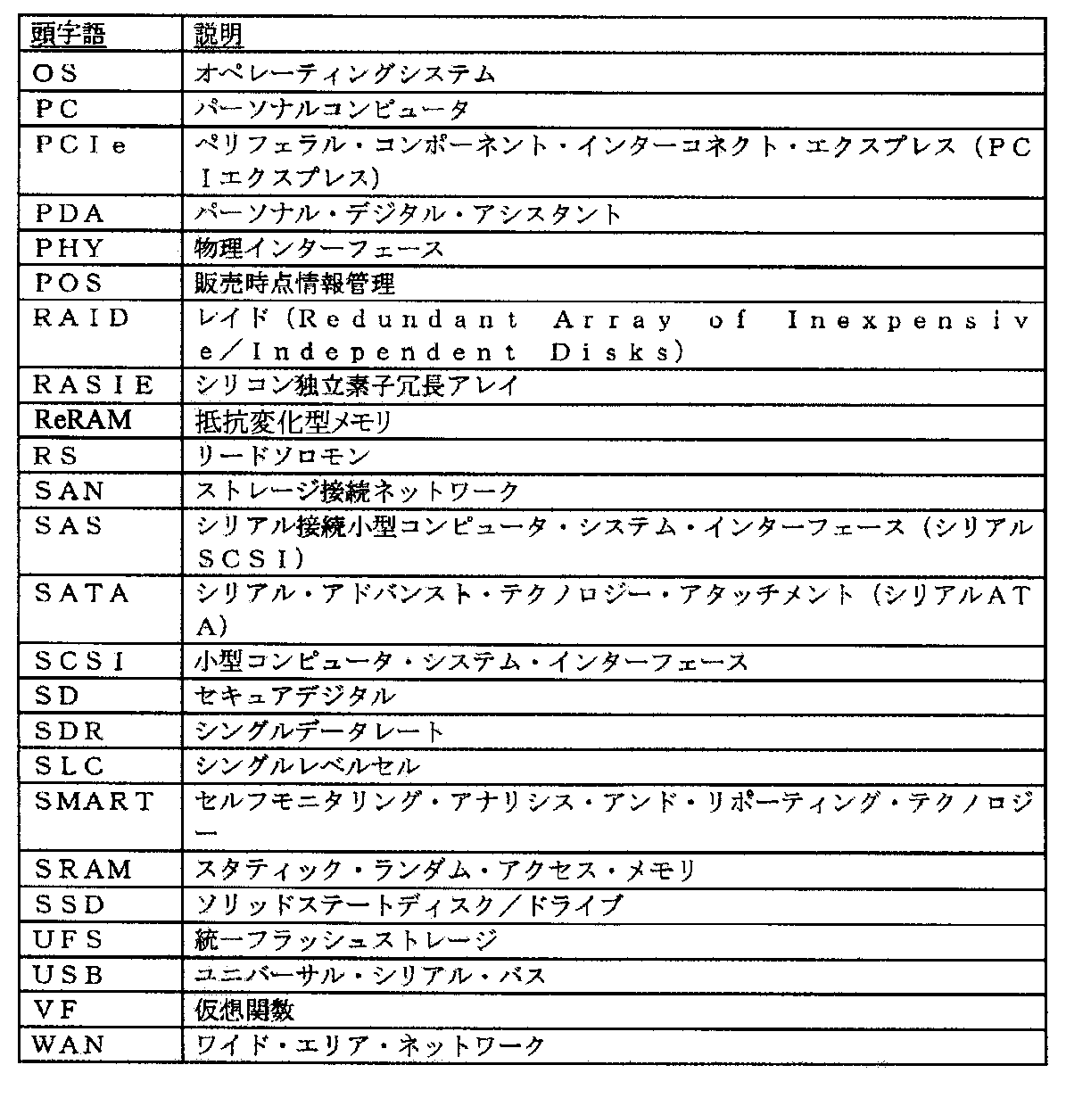
略語
ここで定義された様々な省略略語(例えば、頭字語)の少なくともいくつかは本明細書にて使用される特定の要素を指す。
Abbreviations At least some of the various abbreviations (eg, acronyms) defined herein refer to specific elements as used herein.
NAND型フラッシュメモリは情報を格納するためにフローティング・ゲート・トランジスタのアレイを使用する。SLC技術では、各ビットセル(例えば、フローティング・ゲート・トランジスタ)は1ビットの情報を格納することが可能である。MLC技術では、各ビットセルは複数ビットの情報を格納することが可能である。製造技術(例えばCMOS技術)が縮小しているので、各フローティングゲートはより少ない電子を格納する。さらに、記憶容量および密度が増加すると、各ビットセルはより多くのビットを格納する。このため、ビットセルに格納された値がより小さい電圧範囲によって表される。時間の経過とともに格納された電子の量の検知の不確実性および/または変化はデータが間違って格納されるまたは読み取られる確率を高める。(例えば下位レベルでの)1つ以上の冗長性および/またはECC技術の使用は、そうでなければ破損したデータをNAND型フラッシュメモリから正確に検索することを可能にし、いくつかの使用シナリオでは上記の困難のいくつかを克服する。 NAND flash memory uses an array of floating gate transistors to store information. In SLC technology, each bit cell (eg, floating gate transistor) can store one bit of information. In MLC technology, each bit cell can store multiple bits of information. Since manufacturing technology (eg, CMOS technology) is shrinking, each floating gate stores fewer electrons. Further, as storage capacity and density increase, each bit cell stores more bits. For this reason, the value stored in the bit cell is represented by a smaller voltage range. Uncertainty and / or changes in the amount of stored electrons over time increase the probability that data is stored or read incorrectly. The use of one or more redundancy and / or ECC techniques (eg, at a lower level) allows for accurate retrieval of otherwise corrupted data from NAND flash memory, and in some usage scenarios Overcoming some of the above difficulties.
いくつかの種類のSSDは不揮発性ストレージ(例えば、フラッシュメモリは電源の供給なしで情報を保持する)を提供するためにフラッシュメモリを使用している。(例えば上位レベルでの)1つ以上のECCおよび/または冗長性技術の使用は、そうでなければ破損したデータをフラッシュメモリから正確に検索することを可能にし、および/または1つ以上のフラッシュメモリ素子が断続的または恒久的に障害を発生する場合であってもSSDの適切なシステムレベルの動作を可能にする。 Some types of SSDs use flash memory to provide non-volatile storage (eg, flash memory retains information without power supply). The use of one or more ECC and / or redundancy techniques (e.g., at a higher level) allows for accurately retrieving otherwise corrupted data from flash memory and / or one or more flashes It enables proper system level operation of the SSD even if the memory device fails intermittently or permanently.
例えば、SSDコントローラは、SSDコントローラにより部分的に実現されるSSDの動作中に1つ以上のNVM(例えば、フラッシュ)素子が障害を発生してもグレースフルデグラデーションを提供するよう、独立したシリコン素子を伴う動的な上位レベルの冗長モードの管理を可能にする。NVMの一部が読み取られる。下位レベルの冗長性および/または誤り訂正(1つ以上のECC技術によってなどの)を使用して訂正できない誤りが発生した場合、次に、上位レベルの冗長および/または誤り訂正(1つ以上のRASIE技術および/または動的な上位レベルの冗長モード管理技術によってなどの)が誤りを訂正しようとするために使用される。NVM素子の1つに、障害が、下位レベルおよび/もしくは上位レベルの冗長および/もしくは誤り訂正により、ならびに/または他の技術(1つ以上のNVM素子により報告される障害ステータスなど)により検出された場合、次に、上位レベルの冗長および/または誤り訂正は現在のモードでの動作から新しいモードでの動作に動的に遷移される。遷移は、SSDの空き領域を減少すること、SSDのデータストレージを再編成すること、障害が発生したユーザデータを復旧/格納すること(可能な場合)、ならびに修正された上位レベルの冗長および/または誤り訂正情報を決定/格納することの1つ以上を含む。そして動作は新しいモードで続行される。もう1つの他のNVM素子のもう1つの他の障害が新しいモードで現在動作する上位レベルの冗長および/または誤り訂正で検出された場合、次に他の遷移が他の上位レベルの冗長および/または誤り訂正モードに行われる。NVMへの書き込みは、上位レベルの冗長および/または誤り訂正動作モードおよび書き込みデータに従って上位レベルの冗長および/または誤り訂正情報を決定/格納することを含む、上位レベルの冗長および/または誤り訂正動作モードに従っている。 For example, the SSD controller may be a separate silicon to provide graceful degradation even if one or more NVM (eg, flash) devices fail during the operation of the SSD partially implemented by the SSD controller. Allows management of dynamic high-level redundancy modes with elements. A portion of the NVM is read. If an error that cannot be corrected using lower level redundancy and / or error correction (such as by one or more ECC techniques) occurs, then higher level redundancy and / or error correction (one or more RASIE techniques and / or dynamic higher level redundancy mode management techniques, etc.) are used to try to correct the error. In one of the NVM elements, a failure is detected by lower and / or higher level redundancy and / or error correction and / or by other techniques (such as a failure status reported by one or more NVM elements). If so, then the higher level redundancy and / or error correction is dynamically transitioned from operating in the current mode to operating in the new mode. Transitions include reducing SSD free space, reorganizing SSD data storage, recovering / storing failed user data (if possible), and modified higher level redundancy and / or Or one or more of determining / storing error correction information. The operation then continues in the new mode. If another other failure of another other NVM device is detected with higher level redundancy and / or error correction currently operating in the new mode, then another transition is then detected with the other higher level redundancy and / or Alternatively, the error correction mode is performed. Writing to the NVM includes determining and storing higher level redundancy and / or error correction information according to the higher level redundancy and / or error correction mode of operation and write data, and higher level redundancy and / or error correction operations. Follow the mode.
しきい値数ならびに/またはしきい値率より多い下位レベルの誤り訂正および/もしくは1つ以上の障害が、或るメモリの領域に対して起こる場合には、任意で、そのメモリの領域は、現在の上位レベルの冗長および/または誤り訂正動作モードより多くの誤りから回復することが可能である、新たな上位レベルの冗長および/または誤り訂正動作モードで動作することに動的に遷移する。例えば、現在の上位レベルの冗長および/または誤り訂正動作モードがない(例えば、下位レベルの冗長の障害から復旧して誤りを訂正するよう計算および/または使用される上位レベルの冗長情報がない)場合、新たな上位レベルの冗長および/または誤り訂正動作モードは、下位レベルの冗長によって訂正できない1つの障害からの復旧を可能にするものである。別の例として、現在の上位レベルの冗長および/または誤り訂正動作モードが、下位レベルの冗長によって訂正できない1つの障害からの復旧を可能にするものである場合には、新たな上位レベルの冗長および/または誤り訂正動作モードは、下位レベルの冗長によって訂正できない2つの障害からの復旧を可能にするものである。 Optionally, if a lower level error correction and / or one or more failures that exceed a threshold number and / or threshold rate occur for an area of memory, A dynamic transition is made to operating in a new higher level redundancy and / or error correction mode of operation that can recover from more errors than the current higher level redundancy and / or error correction mode of operation. For example, there is no current higher level redundancy and / or error correction mode of operation (eg, no higher level redundancy information is calculated and / or used to recover from a lower level redundancy failure and correct the error) In some cases, the new higher level redundancy and / or error correction mode of operation allows recovery from a single failure that cannot be corrected by lower level redundancy. As another example, if the current higher level redundancy and / or error correction mode of operation allows recovery from a single failure that cannot be corrected by the lower level redundancy, a new higher level redundancy is provided. And / or error correction mode of operation allows recovery from two failures that cannot be corrected by lower level redundancy.
上位レベルの冗長および/または誤り訂正情報を決定/格納することは、いくつかの実施形態および/または使用シナリオでは、上位レベルの冗長情報の計算に従っている。上位レベルの冗長情報の計算は、SSDコントローラが、SSDコントローラにより部分的に実現されるSSDの動作中に不揮発性(例えば、フラッシュ)メモリ素子の障害のコンテキストで信頼性の高い動作を維持するために上位レベルの冗長性機能を提供することを可能にする。上位レベルの冗長情報の第1の部分は、上位レベルの冗長情報により保護されるデータの部分における全ページのXOR(例えば、ストライプ)を介してパリティ符号化を用いて計算される。上位レベルの冗長情報の第2の部分は、加重和を計算する際に該部分の各ページが加重として一意の非ゼロの「インデックス」を割り当てられる、加重和技術を使用して計算される。算術計算は有限体(例えば、ガロア体として、またはpが素数である、pを法とする整数など)を介して実行される。 Determining / storing higher level redundancy and / or error correction information is in some embodiments and / or usage scenarios, according to the calculation of higher level redundancy information. The calculation of the higher level redundancy information is for the SSD controller to maintain a reliable operation in the context of the failure of the non-volatile (eg flash) memory device during the operation of the SSD partially realized by the SSD controller. It is possible to provide a higher level redundancy function. The first part of the higher level redundant information is calculated using parity encoding via XOR (eg, stripes) of all pages in the portion of data protected by the higher level redundant information. The second part of the higher level redundancy information is calculated using a weighted sum technique in which each page of the part is assigned a unique non-zero “index” as a weight when calculating the weighted sum. Arithmetic calculations are performed via a finite field (eg, as a Galois field, or an integer modulo p, where p is a prime number).
上位レベルの冗長情報の一部は、NVM素子上で実行される1つ以上の読み取り動作の完了の順序により決定される順序など、または、NVM素子から返送されるおよび/または利用可能なデータの順序に基づいた順序などの、任意の順序で計算可能であり、様々な実施形態で、低減または除去されたバッファリングを可能にする。任意の順序での計算可能性は、様々な実施形態で、比較的少ない一時的および/または中間のバッファリングおよび/または状態を使用して復旧データ値を計算することおよび/または書き込みをバックアウトすることを可能にする。上位レベルの冗長情報の一部は、様々な実施形態で、低減された遅延処理および/または低減されたメモリ(例えば、NVM)帯域幅の使用を可能にする、利用可能な専用のハードウェア要素により決定されるような、並列処理の任意の程度で計算可能である。 Some of the higher level redundancy information may be in an order determined by the order of completion of one or more read operations performed on the NVM element, or of data returned and / or available from the NVM element. It can be computed in any order, such as an order based order, and in various embodiments allows reduced or eliminated buffering. Computability in any order can be calculated in various embodiments using relatively little temporary and / or intermediate buffering and / or state to calculate recovery data values and / or write out Make it possible to do. Some of the higher level redundancy information is a dedicated hardware element available that, in various embodiments, enables reduced delay processing and / or reduced memory (eg, NVM) bandwidth usage. Can be computed with any degree of parallel processing, as determined by
或る数および/または率の下位レベルの誤り事象(例えば、訂正可能および/または訂正不可能誤り)および/または障害がNVMの様々な領域で異なるように生じるなんらかの情況では、NVMに対する混合粒度の上位レベルの冗長は、改善された上位レベルの冗長動作をよりよい誤り回復および/または低減された冗長情報オーバーヘッドで可能にする。ある場合では、よりよい誤り回復は、結果として、NVMおよび/またはNVMと共に実現されるSSDの使用可能な寿命の増大をもたらす。 In some circumstances where a certain number and / or rate of lower level error events (eg, correctable and / or uncorrectable errors) and / or failures occur differently in different areas of the NVM, the mixed granularity for the NVM Higher level redundancy allows improved higher level redundancy operations with better error recovery and / or reduced redundancy information overhead. In some cases, better error recovery results in an increase in the usable lifetime of the SSD implemented with NVM and / or NVM.
例として、まず、NVMのページはすべて、おおよそ等しい率の下位レベルの誤り事象を有する。NVMのブロックはすべて、最初は、単一動作の間に生じる単一の下位レベルの訂正できない誤りからの回復を可能にする第1の上位レベルの冗長モードで動作される。次いで、NVMの信頼性において変化があり、NVMのいくつかのページはより信頼性がなくなり(例えば、より多くの量の下位レベルの誤り事象を有し始める)、一方で、NVMのすべての他のページは信頼性のあるままである(例えば、同じまたはほとんど同じ量の下位レベルの誤り事象を有し続ける)。前述の下位レベルの事象の量は、例えば下位レベルの事象の数、率、および/または深刻度である。 As an example, first, all NVM pages have an approximately equal rate of lower level error events. All NVM blocks are initially operated in a first higher level redundancy mode that allows recovery from a single lower level uncorrectable error that occurs during a single operation. Then there is a change in the reliability of the NVM, and some pages of the NVM become less reliable (eg, begin to have a greater amount of lower level error events), while all other NVM's Pages remain reliable (eg, continue to have the same or nearly the same amount of lower level error events). The amount of lower level events described above is, for example, the number, rate, and / or severity of lower level events.
概念的には、信頼性における変化の後、NVMは2つの領域:もっぱら信頼性のあるページを有するブロックである第1の領域、および少なくとも1つの信頼性のないページを有するブロックである第2の領域を有する。信頼性における変化に応答して、第2の領域は、単一動作の間に生じる2つの下位レベルの訂正できない誤りからの回復を可能にする第2の上位レベルの冗長モードで部分的に動作されることに、選択的に動的に遷移する。遷移は選択的で部分的であり、なぜなら、より信頼性のないページのみが第2の上位レベルの冗長モードで動作されることに遷移され、一方、第2の領域の信頼性のあるページは第1の上位レベルの冗長モードで動作され続けるからである。一方、第1の領域のブロックはすべて第1の上位レベルの冗長モードで動作され続ける。 Conceptually, after a change in reliability, the NVM has two regions: a first region that is exclusively a block with a reliable page and a second block that has at least one unreliable page. It has the area of. In response to a change in reliability, the second region operates partially in a second higher level redundancy mode that allows recovery from two lower level uncorrectable errors that occur during a single operation. In doing so, it selectively transitions dynamically. The transition is selective and partial, because only the less reliable pages are transitioned to operate in the second higher level redundancy mode, while the reliable pages in the second region are This is because the operation continues in the first higher level redundancy mode. On the other hand, all blocks in the first region continue to operate in the first higher level redundancy mode.
第2の領域は、ページ粒度の上位レベルの冗長で動作されるとして記述され、なぜならば、上位レベルの冗長モードはページによって変動するからである(例えば、信頼性のあるページは第1の上位レベルの冗長モードで動作され、より信頼性のないページは第2の上位レベルの冗長モードで動作される)。対照的に、第1の領域は、ブロック粒度の上位レベルの冗長で動作されるとして記述され、なぜならば、上位レベルの冗長モードは領域のすべてのブロックに対して同じであるからである(例えば、ブロックのすべてが第1の上位レベルの冗長モードでされる)。第1の領域がR−ブロック全体(ここにおいて別記される)である場合は、第1の領域は、R−ブロック粒度の上位レベルの冗長で動作されるとして代替的に記述可能であり、なぜならば、上位レベルの冗長モードは領域のすべてのR−ブロックに対して同じであるからである(例えば、R−ブロック全体は、第1の上位レベルの冗長モードで動作される)。 The second region is described as being operated with higher granularity of page granularity because the upper level redundancy mode varies from page to page (eg, a reliable page is the first higher level of redundancy). Pages that are operated in the level redundancy mode and are less reliable are operated in the second higher level redundancy mode). In contrast, the first region is described as being operated with higher granularity of block granularity because the upper level redundancy mode is the same for all blocks in the region (eg, , All of the blocks are in the first higher level redundancy mode). If the first region is the entire R-block (discussed elsewhere herein), the first region can alternatively be described as being operated with a higher level of redundancy of R-block granularity, because For example, the higher level redundancy mode is the same for all R-blocks in the region (eg, the entire R-block is operated in the first higher level redundancy mode).
例を結論付けると、より信頼性のないページを第2の上位レベルの冗長モードにおいて動作させることは、より信頼性のないページを第1の上位レベルの冗長モードで動作させておくよりも、よい誤り回復を可能にする。代替的に、より信頼性のないページのみを第2の上位レベルの冗長モードにおいて動作させることは、信頼性のないページのいずれかを有するブロックのすべてを第2の上位レベルの冗長モードにおいて動作させることと比較して、冗長情報オーバーヘッドを低減することを可能にする。 To conclude the example, running a less reliable page in the second higher level redundancy mode is better than keeping a less reliable page running in the first higher level redundancy mode. Enables good error recovery. Alternatively, operating only the less reliable pages in the second higher level redundancy mode will cause all blocks with any of the unreliable pages to operate in the second higher level redundancy mode. It is possible to reduce redundant information overhead as compared to
例示的実施形態
詳細な記載への導入部を結論付けることにおいて、この後に続くのは、例示的実施形態の集合であり、少なくともいくつかが明示的にEC(例示的組合わせ)として列挙されて含まれ、ここに記載される概念に従って様々な実施形態のタイプのさらなる記載を提供し;これらの例は、相互排除的、網羅的、または限定的であるようには意味されず;本発明はこれらの例示的実施形態に限定されず、発行された請求項およびそれらの均等物の範囲内におけるすべての可能な修正および変形を包含する。
Exemplary Embodiments In concluding with an introduction to the detailed description, what follows is a collection of exemplary embodiments, at least some of which are explicitly listed as EC (Exemplary Combinations) Which are included and provide further description of the various types of embodiments in accordance with the concepts described herein; these examples are not meant to be mutually exclusive, exhaustive, or limiting; It is not limited to these exemplary embodiments, but encompasses all possible modifications and variations within the scope of the issued claims and their equivalents.
EC1)M個の情報部分をメモリのM個のそれぞれの領域において格納することを含む第1の上位レベルの冗長モードで動作することを含み、M個のそれぞれの領域の各々は同じ第1のサイズであり;さらに、
N個の情報部分をメモリのN個のそれぞれの領域において格納することを含む第2の上位レベルの冗長モードで動作することを含み、N個のそれぞれの領域の各々は同じ第2のサイズであり;
M個の情報部分は、それぞれのM−J個のデータ情報部分、およびそれぞれのM−J個のデータ情報部分を保護するために計算されるそれぞれのJ個の冗長情報部分を含み;
N個の情報部分は、それぞれのN−K個のデータ情報部分、およびそれぞれのN−K個のデータ情報部分を保護するために計算されるそれぞれのK個の冗長情報部分を含み;
M個のそれぞれの領域の各々およびN個のそれぞれの領域は、メモリの非重複領域であり;
第1のサイズは第2のサイズと異なり;
M個のそれぞれの領域の各々は、メモリのM個の物理デバイスのそれぞれの1つにあり、N個のそれぞれの領域の各々は、メモリのN個の物理デバイスのそれぞれの1つにある、方法。
EC1) operating in a first higher level redundancy mode including storing M information portions in M respective regions of the memory, each of the M respective regions having the same first Size;
Including operating in a second higher level redundancy mode including storing N information portions in N respective regions of the memory, each of the N respective regions having the same second size. Yes;
The M information parts include respective MJ data information parts and respective J redundant information parts calculated to protect each MJ data information part;
N information portions include respective NK data information portions and respective K redundant information portions calculated to protect each NK data information portion;
Each of the M respective regions and the N respective regions are non-overlapping regions of the memory;
The first size is different from the second size;
Each of the M respective regions is in a respective one of the M physical devices of the memory, and each of the N respective regions is in a respective one of the N physical devices of the memory, Method.
EC2)M個の物理デバイスの少なくともいくつかはN個の物理デバイスの少なくともいくつかである、EC1の方法。 EC2) The method of EC1, wherein at least some of the M physical devices are at least some of the N physical devices.
EC3)M個の物理デバイスはN個の物理デバイスである、EC1の方法。
EC4)第1の上位レベルの冗長モードで動作することおよび第2の上位レベルの冗長モードで動作することは、並行してアクティブであり、少なくとも一部の時間の間、メモリは、N個の情報部分の格納に対応する情報を有することと並行して、M個の情報部分の格納に対応する情報を有する、EC1の方法。
EC3) The method of EC1, wherein the M physical devices are N physical devices.
EC4) Operating in the first higher level redundancy mode and operating in the second higher level redundancy mode are active in parallel, and for at least some time, the memory The method of EC1, comprising information corresponding to storage of M information parts in parallel with having information corresponding to storage of information parts.
EC5)第2の上位レベルの冗長モードで動作することは、製造欠陥、処理変動、一様でない損耗、信頼性または誤り率における観測された変化、および障害のいずれか1つ以上に応答するものである、EC4の方法。 EC5) Operating in a second higher level redundancy mode is responsive to any one or more of manufacturing defects, process variations, uneven wear, observed changes in reliability or error rate, and faults EC4 method.
EC6)M個のそれぞれの領域の任意の1つまたはN個のそれぞれの領域の任意の1つである特定の領域に全体的に含まれる1つ以上の位置にアクセスすることをさらに含み、アクセスすることは特定の領域のサイズを判断することを含む、EC1の方法。 EC6) further comprising accessing one or more locations generally included in a particular region that is any one of the M respective regions or any one of the N respective regions. The method of EC1, wherein doing includes determining a size of a particular region.
EC7)メモリは複数のフラッシュデバイスを含む、EC1の方法。
EC8)M個のそれぞれの領域は、複数のフラッシュデバイスの1つ以上のM個のそれぞれのブロックに対応する、EC7の方法。
EC7) The method of EC1, wherein the memory includes a plurality of flash devices.
EC8) The method of EC7, wherein each of the M regions corresponds to one or more M blocks of the plurality of flash devices.
EC9)1つ以上のフラッシュデバイスは第1の1つ以上のフラッシュデバイスであり、N個のそれぞれの領域は複数のフラッシュデバイスの第2の1つ以上のN個のそれぞれのページに対応する、EC8の方法。 EC9) The one or more flash devices are a first one or more flash devices, and each of the N regions corresponds to a second one or more N respective pages of the plurality of flash devices. EC8 method.
EC10)第1の1つ以上のフラッシュデバイスの少なくとも1つおよび第2の1つ以上のフラッシュデバイスの少なくとも1つは、同じフラッシュデバイスである、EC9の方法。 EC10) The method of EC9, wherein at least one of the first one or more flash devices and at least one of the second one or more flash devices are the same flash device.
EC11)同じフラッシュデバイスは1つ以上のフラッシュダイを有する集積回路を含む、EC10の方法。 EC11) The method of EC10, wherein the same flash device comprises an integrated circuit having one or more flash dies.
EC12)同じフラッシュデバイスは単一のフラッシュダイを含む、EC10の方法。
EC13)M個の情報部分をメモリのM個のそれぞれの領域において格納することを含む第1の上位レベルの冗長モードで動作することを含み、M個のそれぞれの領域の各々は同じ第1のタイプであり;さらに、
N個の情報部分をメモリのN個のそれぞれの領域において格納することを含む第2の上位レベルの冗長モードで動作することを含み、N個のそれぞれの領域の各々は同じ第2のタイプであり;
M個の情報部分は、それぞれのM−J個のデータ情報部分、およびそれぞれのM−J個のデータ情報部分を保護するために計算されるそれぞれのJ個の冗長情報部分を含み;
N個の情報部分は、それぞれのN−K個のデータ情報部分、およびそれぞれのN−K個のデータ情報部分を保護するために計算されるそれぞれのK個の冗長情報部分を含み;
M個のそれぞれの領域の各々およびN個のそれぞれの領域は、メモリの非重複領域であり;
第1のタイプは第2のタイプと異なり;
M個のそれぞれの領域の各々は、メモリのM個の物理デバイスのそれぞれの1つにあり、N個のそれぞれの領域の各々は、メモリのN個の物理デバイスのそれぞれの1つにある、方法。
EC12) The method of EC10, wherein the same flash device comprises a single flash die.
EC13) comprising operating in a first higher level redundancy mode including storing M information portions in M respective regions of the memory, each of the M respective regions having the same first Type;
Operating in a second higher level redundancy mode including storing N information portions in N respective regions of the memory, each of the N respective regions being of the same second type Yes;
The M information parts include respective MJ data information parts and respective J redundant information parts calculated to protect each MJ data information part;
N information portions include respective NK data information portions and respective K redundant information portions calculated to protect each NK data information portion;
Each of the M respective regions and the N respective regions are non-overlapping regions of the memory;
The first type is different from the second type;
Each of the M respective regions is in a respective one of the M physical devices of the memory, and each of the N respective regions is in a respective one of the N physical devices of the memory, Method.
EC14)メモリは複数のフラッシュデバイスを含み;
M個のそれぞれの領域はフラッシュデバイスの第1の1つ以上のM個のそれぞれのブロックに対応し、第1のタイプはブロックタイプであり;
N個のそれぞれの領域はフラッシュデバイスの第2の1つ以上のN個のそれぞれのページに対応し、第2のタイプはページタイプである、EC13の方法。
EC14) The memory includes a plurality of flash devices;
M respective regions correspond to the first one or more M respective blocks of the flash device, the first type being a block type;
The EC13 method, wherein each of the N regions corresponds to a second one or more N pages of the flash device, and the second type is a page type.
EC15)M個のそれぞれのブロックの1つの障害を検出すること、および応答して、少なくとも障害を起こしたブロックを第2の上位レベルの冗長モードで動作することをさらに含む、EC14の方法。 EC15) The method of EC14, further comprising detecting a failure of one of each of the M blocks and operating in response to at least the failed block in a second higher level redundancy mode.
EC16)JはKと等しくない、EC1またはEC13の方法。
EC17)MはNと等しい、EC16の方法。
EC16) The method of EC1 or EC13, wherein J is not equal to K.
EC17) The method of EC16, wherein M is equal to N.
EC18)MはNと等しい、EC1またはEC13の方法。
EC19)MはNと等しくない、EC1またはEC13の方法。
EC18) The method of EC1 or EC13, wherein M is equal to N.
EC19) The method of EC1 or EC13, wherein M is not equal to N.
EC20)JはKと等しくない、EC19の方法。
EC21)メモリの領域の少なくともいくつかはフラッシュメモリを含み、格納する行為の1つ以上は、少なくとも一部が、フラッシュメモリに結合され少なくとも1つのフラッシュメモリインターフェース規格と適合するフラッシュメモリインターフェースを介する、EC1またはEC13の方法。
EC20) The method of EC19, wherein J is not equal to K.
EC21) At least some of the areas of memory include flash memory, and one or more of the acts of storing is via a flash memory interface that is at least partially coupled to the flash memory and compatible with at least one flash memory interface standard. EC1 or EC13 method.
EC22)メモリの領域の少なくともいくつかはフラッシュメモリを含み、格納する行為の1つ以上は、少なくとも一部が、少なくとも1つのストレージインターフェース規格と適合するホストインターフェースを介してホストから受取られる要求に応答する、EC1またはEC13の方法。 EC22) At least some of the areas of memory include flash memory, and one or more of the acts of storing is responsive at least in part to a request received from a host via a host interface compatible with at least one storage interface standard. EC1 or EC13 method.
EC23)メモリの領域の少なくともいくつかはフラッシュメモリを含み、格納する行為の1つ以上は、少なくとも一部が、フラッシュメモリに結合され少なくとも1つのフラッシュメモリインターフェース規格と適合するフラッシュメモリインターフェースを介し、格納する行為の少なくとも1つは、少なくとも一部が、少なくとも1つのストレージインターフェース規格と適合するホストインターフェースを介してホストから受取られる要求に応答する、EC1またはEC13の方法。 EC23) At least some of the areas of memory include flash memory, and one or more of the acts of storing is via a flash memory interface that is at least partially coupled to the flash memory and compatible with at least one flash memory interface standard; The EC1 or EC13 method, wherein at least one of the storing acts is at least partially responsive to a request received from a host via a host interface compatible with at least one storage interface standard.
EC24)フラッシュメモリインターフェースおよびホストインターフェースは単一の集積回路(IC)においてまとめて実現される、EC23の方法。 EC24) The method of EC23, wherein the flash memory interface and the host interface are implemented together in a single integrated circuit (IC).
EC25)フラッシュメモリインターフェースおよびホストインターフェースはソリッドステートディスク(SSD)に含まれる、EC23の方法。 EC25) The method of EC23, wherein the flash memory interface and the host interface are included in a solid state disk (SSD).
EC26)フラッシュメモリにおいて、少なくとも一部が、格納する行為の少なくとも1つに応答して生成される、1つ以上の書き込みおよび/またはプログラミングコマンドを受けることをさらに含む、EC23の方法。 EC26) The method of EC23, further comprising receiving, in the flash memory, at least one or more write and / or programming commands generated in response to at least one of the storing acts.
EC27)ホストにおいて要求を生成することをさらに含む、EC23の方法。
EC28)それぞれの第1および第2の上位レベルの冗長モードに従ってメモリを管理するための手段と;
メモリを管理するための手段に応答して、メモリに格納するための手段とを含み;
メモリを管理するための手段は、格納するための手段に対して、M個の情報部分をメモリのM個のそれぞれの領域に格納するように指示することが可能となっており、M個のそれぞれの領域の各々は同じ第1のサイズであり;
メモリを管理するための手段は、さらに、格納するための手段に対して、N個の情報部分をメモリのN個のそれぞれの領域に格納するように指示することが可能となっており、N個のそれぞれの領域の各々は同じ第2のサイズであり;
M個の情報部分は、それぞれのM−J個のデータ情報部分、およびそれぞれのM−J個のデータ情報部分を保護するために計算されるそれぞれのJ個の冗長情報部分を含み;
N個の情報部分は、それぞれのN−K個のデータ情報部分、およびそれぞれのN−K個のデータ情報部分を保護するために計算されるそれぞれのK個の冗長情報部分を含み;
M個のそれぞれの領域の各々およびN個のそれぞれの領域は、メモリの非重複領域であり;
第1のサイズは第2のサイズと異なり;
M個のそれぞれの領域の各々は、メモリのM個の物理デバイスのそれぞれの1つにあり、N個のそれぞれの領域の各々は、メモリのN個の物理デバイスのそれぞれの1つにある、システム。
EC27) The method of EC23, further comprising generating a request at the host.
EC28) means for managing the memory according to respective first and second higher level redundancy modes;
Means for storing in the memory in response to the means for managing the memory;
The means for managing the memory can instruct the means for storing to store the M information parts in each of the M areas of the memory. Each of the respective regions is the same first size;
The means for managing the memory can further instruct the means for storing to store N pieces of information in each of the N areas of the memory. Each of the respective regions is the same second size;
The M information parts include respective MJ data information parts and respective J redundant information parts calculated to protect each MJ data information part;
N information portions include respective NK data information portions and respective K redundant information portions calculated to protect each NK data information portion;
Each of the M respective regions and the N respective regions are non-overlapping regions of the memory;
The first size is different from the second size;
Each of the M respective regions is in a respective one of the M physical devices of the memory, and each of the N respective regions is in a respective one of the N physical devices of the memory, system.
EC29)M個の物理デバイスの少なくともいくつかはN個の物理デバイスの少なくともいくつかである、EC28のシステム。 EC29) The system of EC28, wherein at least some of the M physical devices are at least some of the N physical devices.
EC30)M個の物理デバイスはN個の物理デバイスである、EC28のシステム。
EC31)メモリを管理するための手段は、第1の上位レベルの冗長モードおよび第2の上位レベルの冗長モードに従ってメモリを並行して管理することが可能となっており、少なくとも一部の時間の間、メモリは、N個の情報部分の格納に対応する情報を有することと並行して、M個の情報部分の格納に対応する情報を有する、EC28のシステム。
EC30) EC28 system, where M physical devices are N physical devices.
EC31) The means for managing the memory is capable of managing the memory in parallel according to the first upper level redundancy mode and the second upper level redundancy mode, and for at least part of the time Meanwhile, the system of EC 28, wherein the memory has information corresponding to the storage of M information parts in parallel with having information corresponding to the storage of N information parts.
EC32)メモリを管理するための手段は、製造欠陥、処理変動、一様でない損耗、信頼性または誤り率における観測された変化、および障害のいずれか1つ以上に応答して、メモリの一部を第1の上位レベルの冗長モードで動作することから第2の上位レベルの冗長モードで動作することに遷移することが可能となっている、EC31のシステム。 EC32) The means for managing the memory is a portion of the memory in response to any one or more of manufacturing defects, process variations, uneven wear, observed changes in reliability or error rate, and faults. The EC31 system is capable of transitioning from operating in the first higher level redundancy mode to operating in the second higher level redundancy mode.
EC33)M個のそれぞれの領域の任意の1つまたはN個のそれぞれの領域の任意の1つである特定の領域に全体的に含まれる1つ以上の位置にアクセスするための手段をさらに含み、アクセスするための手段は特定の領域のサイズを判断することが可能となっている、EC28のシステム。 EC33) further comprising means for accessing one or more locations generally included in a particular region that is any one of the M respective regions or any one of the N respective regions. The EC28 system allows access means to determine the size of a particular area.
EC34)メモリは複数のフラッシュデバイスを含む、EC28のシステム。
EC35)M個のそれぞれの領域は、複数のフラッシュデバイスの1つ以上のM個のそれぞれのブロックに対応する、EC34のシステム。
EC34) The EC28 system, wherein the memory includes a plurality of flash devices.
EC35) The system of EC34, wherein each of the M regions corresponds to one or more M respective blocks of the plurality of flash devices.
EC36)1つ以上のフラッシュデバイスは第1の1つ以上のフラッシュデバイスであり、N個のそれぞれの領域は複数のフラッシュデバイスの第2の1つ以上のN個のそれぞれのページに対応する、EC35のシステム。 EC36) The one or more flash devices are a first one or more flash devices, and each of the N regions corresponds to a second one or more N respective pages of the plurality of flash devices. EC35 system.
EC37)第1の1つ以上のフラッシュデバイスの少なくとも1つおよび第2の1つ以上のフラッシュデバイスの少なくとも1つは、同じフラッシュデバイスである、EC36のシステム。 EC37) The system of EC36, wherein at least one of the first one or more flash devices and at least one of the second one or more flash devices are the same flash device.
EC38)同じフラッシュデバイスは1つ以上のフラッシュダイを有する集積回路を含む、EC37のシステム。 EC38) The system of EC37, wherein the same flash device includes an integrated circuit having one or more flash dies.
EC39)同じフラッシュデバイスは単一のフラッシュダイを含む、EC37のシステム。 EC39) EC37 system, where the same flash device contains a single flash die.
EC40)それぞれの第1および第2の上位レベルの冗長モードに従ってメモリを管理するための手段と;
メモリを管理するための手段に応答して、メモリに格納するための手段とを含み;
メモリを管理するための手段は、格納するための手段に対して、M個の情報部分をメモリのM個のそれぞれの領域に格納するように指示することが可能となっており、M個のそれぞれの領域の各々は同じ第1のタイプであり;
メモリを管理するための手段は、さらに、格納するための手段に対して、N個の情報部分をメモリのN個のそれぞれの領域に格納するように指示することが可能となっており、N個のそれぞれの領域の各々は同じ第2のタイプであり;
M個の情報部分は、それぞれのM−J個のデータ情報部分、およびそれぞれのM−J個のデータ情報部分を保護するために計算されるそれぞれのJ個の冗長情報部分を含み;
N個の情報部分は、それぞれのN−K個のデータ情報部分、およびそれぞれのN−K個のデータ情報部分を保護するために計算されるそれぞれのK個の冗長情報部分を含み;
M個のそれぞれの領域の各々およびN個のそれぞれの領域は、メモリの非重複領域であり;
第1のタイプは第2のタイプと異なり;
M個のそれぞれの領域の各々は、メモリのM個の物理デバイスのそれぞれの1つにあり、N個のそれぞれの領域の各々は、メモリのN個の物理デバイスのそれぞれの1つにある、システム。
EC40) means for managing the memory according to respective first and second higher level redundancy modes;
Means for storing in the memory in response to the means for managing the memory;
The means for managing the memory can instruct the means for storing to store the M information parts in each of the M areas of the memory. Each of the respective regions is the same first type;
The means for managing the memory can further instruct the means for storing to store N pieces of information in each of the N areas of the memory. Each of the respective regions is of the same second type;
The M information parts include respective MJ data information parts and respective J redundant information parts calculated to protect each MJ data information part;
N information portions include respective NK data information portions and respective K redundant information portions calculated to protect each NK data information portion;
Each of the M respective regions and the N respective regions are non-overlapping regions of the memory;
The first type is different from the second type;
Each of the M respective regions is in a respective one of the M physical devices of the memory, and each of the N respective regions is in a respective one of the N physical devices of the memory, system.
EC41)メモリは複数のフラッシュデバイスを含み;
M個のそれぞれの領域はフラッシュデバイスの第1の1つ以上のM個のそれぞれのブロックに対応し、第1のタイプはブロックタイプであり;
N個のそれぞれの領域はフラッシュデバイスの第2の1つ以上のN個のそれぞれのページに対応し、第2のタイプはページタイプである、EC40のシステム。
EC41) the memory includes a plurality of flash devices;
M respective regions correspond to the first one or more M respective blocks of the flash device, the first type being a block type;
The EC40 system, wherein each of the N regions corresponds to a second one or more N pages of the flash device, and a second type is a page type.
EC42)メモリを管理するための手段は、M個のそれぞれのブロックの1つの障害を検出すること、およびその検出に応答して、少なくとも障害を起こしたブロックを第2の上位レベルの冗長モードで動作させることが、可能となっている、EC41のシステム。 EC42) The means for managing the memory detects a failure of one of each of the M blocks and, in response to the detection, at least the failed block in the second higher level redundancy mode. EC41 system that can be operated.
EC43)JはKと等しくない、EC28またはEC40のシステム。
EC44)MはNと等しい、EC43のシステム。
EC43) EC28 or EC40 system, where J is not equal to K.
EC44) EC43 system, where M is equal to N.
EC45)MはNと等しい、EC28またはEC40のシステム。
EC46)MはNと等しくない、EC28またはEC40のシステム。
EC45) EC28 or EC40 system, where M is equal to N.
EC46) EC28 or EC40 system, where M is not equal to N.
EC47)JはKと等しくない、EC46のシステム。
EC48)メモリの領域の少なくともいくつかはフラッシュメモリを含み、格納する手段は、フラッシュメモリに結合され少なくとも1つのフラッシュメモリインターフェース規格と適合するフラッシュメモリインターフェースを含む、EC28またはEC40のシステム。
EC47) EC46 system, where J is not equal to K.
EC48) The EC28 or EC40 system, wherein at least some of the areas of memory include flash memory and the means for storing includes a flash memory interface coupled to the flash memory and compatible with at least one flash memory interface standard.
EC49)メモリの領域の少なくともいくつかはフラッシュメモリを含み、格納することの少なくとも一部は、少なくとも一部が、少なくとも1つのストレージインターフェース規格と適合するホストインターフェースを介してホストから受取られる要求に応答する、EC28またはEC40のシステム。 EC49) At least some of the areas of memory include flash memory and at least some of the storage is responsive to requests received from the host via a host interface that is at least partially compatible with at least one storage interface standard. EC28 or EC40 system.
EC50)メモリの領域の少なくともいくつかはフラッシュメモリを含み、格納する手段は、フラッシュメモリに結合され少なくとも1つのフラッシュメモリインターフェース規格と適合するフラッシュメモリインターフェースを含み、格納することの少なくとも一部は、少なくとも一部が、少なくとも1つのストレージインターフェース規格と適合するホストインターフェースを介してホストから受取られる要求に応答する、EC28またはEC40のシステム。 EC50) At least some of the areas of memory include flash memory, and the means for storing includes a flash memory interface coupled to the flash memory and compatible with at least one flash memory interface standard, at least a portion of storing is An EC28 or EC40 system, at least in part, responsive to a request received from a host via a host interface compatible with at least one storage interface standard.
EC51)フラッシュメモリインターフェースおよびホストインターフェースは単一の集積回路(IC)においてまとめて実現される、EC50のシステム。 EC51) The EC50 system in which the flash memory interface and the host interface are implemented together in a single integrated circuit (IC).
EC52)フラッシュメモリインターフェースおよびホストインターフェースはソリッドステートディスク(SSD)に含まれる、EC50のシステム。 EC52) The EC50 system, where the flash memory interface and host interface are contained in a solid state disk (SSD).
EC53)フラッシュメモリにおいて、少なくとも一部が、格納することの少なくとも一部に応答して生成される、1つ以上の書き込みおよび/またはプログラミングコマンドを受けるための手段をさらに含む、EC50のシステム。 EC53) The system of EC50, further comprising means in the flash memory for receiving one or more write and / or programming commands, at least part of which is generated in response to at least part of the storing.
EC54)フラッシュメモリの任意の部分をさらに含む、EC53のシステム。
EC55)ホストにおいて、要求を生成するための手段をさらに含む、EC50のシステム。
EC54) The system of EC53, further comprising any part of the flash memory.
EC55) The system of EC50, further comprising means for generating a request at the host.
EC56)ホストの任意の部分をさらに含む、EC55のシステム。
EC57)それぞれの第1および第2の上位レベルの冗長モードに従ってメモリを制御することが可能となっている上位レベルの冗長制御回路系と;
上位レベルの冗長制御回路系に応答するストレージ回路系とを含み;
上位レベルの冗長制御回路系は、ストレージ回路系に対して、M個の情報部分をメモリのM個のそれぞれの領域に格納するように指示することが可能となっており、M個のそれぞれの領域の各々は同じ第1のサイズであり;
上位レベルの冗長制御回路系は、さらに、ストレージ回路系に対して、N個の情報部分をメモリのN個のそれぞれの領域に格納するように指示することが可能となっており、N個のそれぞれの領域の各々は同じ第2のサイズであり;
M個の情報部分は、それぞれのM−J個のデータ情報部分、およびそれぞれのM−J個のデータ情報部分を保護するために計算されるそれぞれのJ個の冗長情報部分を含み;
N個の情報部分は、それぞれのN−K個のデータ情報部分、およびそれぞれのN−K個のデータ情報部分を保護するために計算されるそれぞれのK個の冗長情報部分を含み;
M個のそれぞれの領域の各々およびN個のそれぞれの領域は、メモリの非重複領域であり;
第1のサイズは第2のサイズと異なり;
M個のそれぞれの領域の各々は、メモリのM個の物理デバイスのそれぞれの1つにあり、N個のそれぞれの領域の各々は、メモリのN個の物理デバイスのそれぞれの1つにある、装置。
EC56) The system of EC55, further including any part of the host.
EC57) an upper level redundancy control circuit system capable of controlling the memory according to respective first and second upper level redundancy modes;
A storage circuit responsive to a higher level redundant control circuit;
The upper level redundancy control circuit system can instruct the storage circuit system to store the M information portions in the M areas of the memory. Each of the regions is the same first size;
The upper level redundancy control circuit system can further instruct the storage circuit system to store N information portions in each of the N areas of the memory. Each of the respective regions is the same second size;
The M information parts include respective MJ data information parts and respective J redundant information parts calculated to protect each MJ data information part;
N information portions include respective NK data information portions and respective K redundant information portions calculated to protect each NK data information portion;
Each of the M respective regions and the N respective regions are non-overlapping regions of the memory;
The first size is different from the second size;
Each of the M respective regions is in a respective one of the M physical devices of the memory, and each of the N respective regions is in a respective one of the N physical devices of the memory, apparatus.
EC58)M個の物理デバイスの少なくともいくつかはN個の物理デバイスの少なくともいくつかである、EC57の装置。 EC58) The apparatus of EC57, wherein at least some of the M physical devices are at least some of the N physical devices.
EC59)M個の物理デバイスはN個の物理デバイスである、EC57の装置。
EC60)上位レベルの冗長制御回路系は、さらに、第1の上位レベルの冗長モードおよび第2の上位レベルの冗長モードに従ってメモリを並行して管理することが可能となっており、少なくとも一部の時間の間、メモリは、N個の情報部分の格納に対応する情報を有することと並行して、M個の情報部分の格納に対応する情報を有する、EC57の装置。
EC59) EC57 apparatus, where M physical devices are N physical devices.
EC60) The upper level redundancy control circuit system can further manage the memory in parallel according to the first upper level redundancy mode and the second upper level redundancy mode, and at least a part of the redundancy control circuit system. The device of EC57, wherein over time, the memory has information corresponding to storage of M information parts in parallel with having information corresponding to storage of N information parts.
EC61)上位レベルの冗長制御回路系は、さらに、製造欠陥、処理変動、一様でない損耗、信頼性または誤り率における観測された変化、および障害のいずれか1つ以上に応答して、メモリの一部を第1の上位レベルの冗長モードで動作することから第2の上位レベルの冗長モードで動作することに遷移することが可能となっている、EC60の装置。 EC61) The upper level redundant control circuitry is further responsive to any one or more of manufacturing defects, process variations, uneven wear, observed changes in reliability or error rate, and faults in memory. The EC60 device, wherein a part can operate from operating in a first higher level redundancy mode to transition to operating in a second higher level redundancy mode.
EC62)M個のそれぞれの領域の任意の1つまたはN個のそれぞれの領域の任意の1つである特定の領域に全体的に含まれる1つ以上の位置にアクセスすることが可能となっているアクセス回路系をさらに含み、アクセス回路系は、さらに、特定の領域のサイズを判断することが可能となっている、EC57の装置。 EC62) It is possible to access one or more locations generally contained in a particular area that is any one of the M respective areas or any one of the N respective areas. The device of EC57, further comprising an access circuit system, wherein the access circuit system is further capable of determining a size of a specific area.
EC63)メモリは複数のフラッシュデバイスを含む、EC57の装置。
EC64)M個のそれぞれの領域は、複数のフラッシュデバイスの1つ以上のM個のそれぞれのブロックに対応する、EC63の装置。
EC63) EC57 apparatus, wherein the memory includes a plurality of flash devices.
EC64) The EC63 device, wherein each M region corresponds to one or more M respective blocks of the plurality of flash devices.
EC65)1つ以上のフラッシュデバイスは第1の1つ以上のフラッシュデバイスであり、N個のそれぞれの領域は複数のフラッシュデバイスの第2の1つ以上のN個のそれぞれのページに対応する、EC64の装置。 EC65) the one or more flash devices are a first one or more flash devices, and each of the N regions corresponds to a second one or more N respective pages of the plurality of flash devices; EC64 device.
EC66)第1の1つ以上のフラッシュデバイスの少なくとも1つおよび第2の1つ以上のフラッシュデバイスの少なくとも1つは、同じフラッシュデバイスである、EC65の装置。 EC66) The apparatus of EC65, wherein at least one of the first one or more flash devices and at least one of the second one or more flash devices are the same flash device.
EC67)同じフラッシュデバイスは1つ以上のフラッシュダイを有する集積回路を含む、EC66の装置。 EC67) The apparatus of EC66, wherein the same flash device comprises an integrated circuit having one or more flash dies.
EC68)同じフラッシュデバイスは単一のフラッシュダイを含む、EC66の装置。
EC69)それぞれの第1および第2の上位レベルの冗長モードに従ってメモリを制御することが可能となっている上位レベルの冗長制御回路系と;
上位レベルの冗長制御回路系に応答するストレージ回路系とを含み;
上位レベルの冗長制御回路系は、ストレージ回路系に対して、M個の情報部分をメモリのM個のそれぞれの領域に格納するように指示することが可能となっており、M個のそれぞれの領域の各々は同じ第1のタイプであり;
上位レベルの冗長制御回路系は、さらに、ストレージ回路系に対して、N個の情報部分をメモリのN個のそれぞれの領域に格納するように指示することが可能となっており、N個のそれぞれの領域の各々は同じ第2のタイプであり;
M個の情報部分は、それぞれのM−J個のデータ情報部分、およびそれぞれのM−J個のデータ情報部分を保護するために計算されるそれぞれのJ個の冗長情報部分を含み;
N個の情報部分は、それぞれのN−K個のデータ情報部分、およびそれぞれのN−K個のデータ情報部分を保護するために計算されるそれぞれのK個の冗長情報部分を含み;
M個のそれぞれの領域の各々およびN個のそれぞれの領域は、メモリの非重複領域であり;
第1のタイプは第2のタイプと異なり;
M個のそれぞれの領域の各々は、メモリのM個の物理デバイスのそれぞれの1つにあり、N個のそれぞれの領域の各々は、メモリのN個の物理デバイスのそれぞれの1つにある、装置。
EC68) The EC66 device, wherein the same flash device comprises a single flash die.
EC69) an upper level redundancy control circuit system capable of controlling the memory according to respective first and second upper level redundancy modes;
A storage circuit responsive to a higher level redundant control circuit;
The upper level redundancy control circuit system can instruct the storage circuit system to store the M information portions in the M areas of the memory. Each of the regions is the same first type;
The upper level redundancy control circuit system can further instruct the storage circuit system to store N information portions in each of the N areas of the memory. Each of the respective areas is the same second type;
The M information parts include respective MJ data information parts and respective J redundant information parts calculated to protect each MJ data information part;
N information portions include respective NK data information portions and respective K redundant information portions calculated to protect each NK data information portion;
Each of the M respective regions and the N respective regions are non-overlapping regions of the memory;
The first type is different from the second type;
Each of the M respective regions is in a respective one of the M physical devices of the memory, and each of the N respective regions is in a respective one of the N physical devices of the memory, apparatus.
EC70)メモリは複数のフラッシュデバイスを含み;
M個のそれぞれの領域はフラッシュデバイスの第1の1つ以上のM個のそれぞれのブロックに対応し、第1のタイプはブロックタイプであり;
N個のそれぞれの領域はフラッシュデバイスの第2の1つ以上のN個のそれぞれのページに対応し、第2のタイプはページタイプである、EC69の装置。
EC70) memory includes a plurality of flash devices;
M respective regions correspond to the first one or more M respective blocks of the flash device, the first type being a block type;
The EC69 apparatus, wherein each of the N regions corresponds to a second one or more N respective pages of the flash device, and a second type is a page type.
EC71)上位レベルの冗長制御回路系は、さらに、M個のそれぞれのブロックの1つの障害を検出すること、およびその検出に応答して、少なくとも障害を起こしたブロックを第2の上位レベルの冗長モードで動作させることが、可能となっている、EC70の装置。 EC71) The upper level redundancy control circuit further detects one fault in each of the M blocks, and in response to the detection, at least the failed block is a second higher level redundancy. EC70 device capable of operating in mode.
EC72)JはKと等しくない、EC57またはEC69の装置。
EC73)MはNと等しい、EC72の装置。
EC72) EC57 or EC69 device where J is not equal to K.
EC73) The device of EC72, where M is equal to N.
EC74)MはNと等しい、EC57またはEC69の装置。
EC75)MはNと等しくない、EC57またはEC69の装置。
EC74) EC57 or EC69 device, where M is equal to N.
EC75) EC57 or EC69 device, where M is not equal to N.
EC76)JはKと等しくない、EC75の装置。
EC77)メモリの領域の少なくともいくつかはフラッシュメモリを含み、ストレージ回路系は、フラッシュメモリに結合され少なくとも1つのフラッシュメモリインターフェース規格と適合するフラッシュメモリインターフェースを含む、EC57またはEC69の装置。
EC76) EC75 device, where J is not equal to K.
EC77) The device of EC57 or EC69, wherein at least some of the areas of the memory include flash memory and the storage circuitry includes a flash memory interface coupled to the flash memory and compatible with at least one flash memory interface standard.
EC78)メモリの領域の少なくともいくつかはフラッシュメモリを含み、格納することの少なくとも一部は、少なくとも一部が、少なくとも1つのストレージインターフェース規格と適合するホストインターフェースを介してホストから受取られる要求に応答する、EC57またはEC69の装置。 EC78) At least some of the areas of memory include flash memory and at least some of the storage is responsive to requests received from the host via a host interface that is at least partially compatible with at least one storage interface standard. EC57 or EC69 device.
EC79)メモリの領域の少なくともいくつかはフラッシュメモリを含み、ストレージ回路系は、フラッシュメモリに結合され少なくとも1つのフラッシュメモリインターフェース規格と適合するフラッシュメモリインターフェースを含み、格納することの少なくとも一部は、少なくとも一部が、少なくとも1つのストレージインターフェース規格と適合するホストインターフェースを介してホストから受取られる要求に応答する、EC57またはEC69の装置。 EC79) At least some of the areas of memory include flash memory, the storage circuitry includes a flash memory interface coupled to the flash memory and compatible with at least one flash memory interface standard, and at least a portion of storing is An EC57 or EC69 device, at least in part, responsive to a request received from a host via a host interface compatible with at least one storage interface standard.
EC80)フラッシュメモリインターフェースおよびホストインターフェースは単一の集積回路(IC)においてまとめて実現される、EC79の装置。 EC80) The device of EC79, wherein the flash memory interface and the host interface are implemented together in a single integrated circuit (IC).
EC81)フラッシュメモリインターフェースおよびホストインターフェースはソリッドステートディスク(SSD)に含まれる、EC79の装置。 EC81) The device of EC79, wherein the flash memory interface and the host interface are contained in a solid state disk (SSD).
EC82)フラッシュメモリは、少なくとも一部が、格納することの少なくとも一部に応答して生成される、1つ以上の書き込みおよび/またはプログラミングコマンドを受けることが可能となっている、EC79の装置。 EC82) The device of EC79, wherein the flash memory is capable of receiving one or more write and / or programming commands, at least a portion of which is generated in response to at least a portion of storing.
EC83)フラッシュメモリの任意の部分をさらに含む、EC82の装置。
EC84)ホストは要求を生成することが可能となっている、EC79の装置。
EC83) The device of EC82, further comprising any portion of flash memory.
EC84) An EC79 device that allows a host to generate a request.
EC85)ホストの任意の部分をさらに含む、EC84の装置。
EC86)処理要素によって実行されると処理要素に動作を実行および/または制御させる命令の組が中に格納される有形的コンピュータ読取可能媒体であって、動作は、
M個の情報部分をメモリのM個のそれぞれの領域において格納することを含む第1の上位レベルの冗長モードで動作することを含み、M個のそれぞれの領域の各々は同じ第1のサイズであり;さらに、
N個の情報部分をメモリのN個のそれぞれの領域において格納することを含む第2の上位レベルの冗長モードで動作することを含み、N個のそれぞれの領域の各々は同じ第2のサイズであり;
M個の情報部分は、それぞれのM−J個のデータ情報部分、およびそれぞれのM−J個のデータ情報部分を保護するために計算されるそれぞれのJ個の冗長情報部分を含み;
N個の情報部分は、それぞれのN−K個のデータ情報部分、およびそれぞれのN−K個のデータ情報部分を保護するために計算されるそれぞれのK個の冗長情報部分を含み;
M個のそれぞれの領域の各々およびN個のそれぞれの領域は、メモリの非重複領域であり;
第1のサイズは第2のサイズと異なり;
M個のそれぞれの領域の各々は、メモリのM個の物理デバイスのそれぞれの1つにあり、N個のそれぞれの領域の各々は、メモリのN個の物理デバイスのそれぞれの1つにある、有形的コンピュータ読取可能媒体。
EC85) The device of EC84, further comprising any part of the host.
EC86) A tangible computer readable medium having stored therein a set of instructions that, when executed by a processing element, cause the processing element to perform and / or control an action,
Including operating in a first higher level redundancy mode including storing M information portions in M respective regions of the memory, each of the M respective regions having the same first size. Yes;
Including operating in a second higher level redundancy mode including storing N information portions in N respective regions of the memory, each of the N respective regions having the same second size. Yes;
The M information parts include respective MJ data information parts and respective J redundant information parts calculated to protect each MJ data information part;
N information portions include respective NK data information portions and respective K redundant information portions calculated to protect each NK data information portion;
Each of the M respective regions and the N respective regions are non-overlapping regions of the memory;
The first size is different from the second size;
Each of the M respective regions is in a respective one of the M physical devices of the memory, and each of the N respective regions is in a respective one of the N physical devices of the memory, Tangible computer readable medium.
EC87)M個の物理デバイスの少なくともいくつかはN個の物理デバイスの少なくともいくつかである、EC86の有形的コンピュータ読取可能媒体。 EC87) A tangible computer readable medium of EC86, wherein at least some of the M physical devices are at least some of the N physical devices.
EC88)M個の物理デバイスはN個の物理デバイスである、EC86の有形的コンピュータ読取可能媒体。 EC88) The tangible computer readable medium of EC86, where M physical devices are N physical devices.
EC89)第1の上位レベルの冗長モードで動作することおよび第2の上位レベルの冗長モードで動作することは、並行してアクティブであり、少なくとも一部の時間の間、メモリは、N個の情報部分の格納に対応する情報を有することと並行して、M個の情報部分の格納に対応する情報を有する、EC86の有形的コンピュータ読取可能媒体。 EC89) Operating in the first higher level redundancy mode and operating in the second higher level redundancy mode are active in parallel, and for at least some time, the memory A tangible computer readable medium of EC86 having information corresponding to storage of M information portions in parallel with having information corresponding to storage of information portions.
EC90)第2の上位レベルの冗長モードで動作することは、製造欠陥、処理変動、一様でない損耗、信頼性または誤り率における観測された変化、および障害のいずれか1つ以上に応答するものである、EC89の有形的コンピュータ読取可能媒体。 EC90) Operating in a second higher level redundancy mode is responsive to any one or more of manufacturing defects, process variations, uneven wear, observed changes in reliability or error rate, and faults EC89's tangible computer-readable medium.
EC91)動作は、M個のそれぞれの領域の任意の1つまたはN個のそれぞれの領域の任意の1つである特定の領域に全体的に含まれる1つ以上の位置にアクセスすることをさらに含み、アクセスすることは特定の領域のサイズを判断することを含む、EC86の有形的コンピュータ読取可能媒体。 EC91) the operation further comprises accessing one or more locations generally contained in a particular region that is any one of the M respective regions or any one of the N respective regions. The tangible computer readable medium of EC86, wherein including and accessing includes determining a size of a particular area.
EC92)メモリは複数のフラッシュデバイスを含む、EC86の有形的コンピュータ読取可能媒体。 EC92) EC86 tangible computer readable medium, wherein the memory includes a plurality of flash devices.
EC93)M個のそれぞれの領域は、複数のフラッシュデバイスの1つ以上のM個のそれぞれのブロックに対応する、EC92の有形的コンピュータ読取可能媒体。 EC93) The tangible computer readable medium of EC92, wherein each of the M regions corresponds to one or more M respective blocks of the plurality of flash devices.
EC94)1つ以上のフラッシュデバイスは第1の1つ以上のフラッシュデバイスであり、N個のそれぞれの領域は複数のフラッシュデバイスの第2の1つ以上のN個のそれぞれのページに対応する、EC93の有形的コンピュータ読取可能媒体。 EC94) The one or more flash devices are a first one or more flash devices, and each of the N regions corresponds to a second one or more N respective pages of the plurality of flash devices. EC93 tangible computer readable medium.
EC95)第1の1つ以上のフラッシュデバイスの少なくとも1つおよび第2の1つ以上のフラッシュデバイスの少なくとも1つは、同じフラッシュデバイスである、EC94の有形的コンピュータ読取可能媒体。 EC95) The tangible computer readable medium of EC94, wherein at least one of the first one or more flash devices and at least one of the second one or more flash devices are the same flash device.
EC96)同じフラッシュデバイスは1つ以上のフラッシュダイを有する集積回路を含む、EC95の有形的コンピュータ読取可能媒体。 EC96) EC95's tangible computer readable medium, wherein the same flash device includes an integrated circuit having one or more flash dies.
EC97)同じフラッシュデバイスは単一のフラッシュダイを含む、EC95の有形的コンピュータ読取可能媒体。 EC97) EC95's tangible computer readable medium, where the same flash device contains a single flash die.
EC98)処理要素によって実行されると処理要素に動作を実行および/または制御させる命令の組が中に格納される有形的コンピュータ読取可能媒体であって、動作は、
M個の情報部分をメモリのM個のそれぞれの領域において格納することを含む第1の上位レベルの冗長モードで動作することを含み、M個のそれぞれの領域の各々は同じ第1のタイプであり;さらに、
N個の情報部分をメモリのN個のそれぞれの領域において格納することを含む第2の上位レベルの冗長モードで動作することを含み、N個のそれぞれの領域の各々は同じ第2のタイプであり;
M個の情報部分は、それぞれのM−J個のデータ情報部分、およびそれぞれのM−J個のデータ情報部分を保護するために計算されるそれぞれのJ個の冗長情報部分を含み;
N個の情報部分は、それぞれのN−K個のデータ情報部分、およびそれぞれのN−K個のデータ情報部分を保護するために計算されるそれぞれのK個の冗長情報部分を含み;
M個のそれぞれの領域の各々およびN個のそれぞれの領域は、メモリの非重複領域であり;
第1のタイプは第2のタイプと異なり;
M個のそれぞれの領域の各々は、メモリのM個の物理デバイスのそれぞれの1つにあり、N個のそれぞれの領域の各々は、メモリのN個の物理デバイスのそれぞれの1つにある、有形的コンピュータ読取可能媒体。
EC98) A tangible computer readable medium having stored therein a set of instructions that, when executed by a processing element, cause the processing element to perform and / or control an action,
Including operating in a first higher level redundancy mode including storing M information portions in M respective regions of the memory, each of the M respective regions being of the same first type. Yes;
Operating in a second higher level redundancy mode including storing N information portions in N respective regions of the memory, each of the N respective regions being of the same second type Yes;
The M information parts include respective MJ data information parts and respective J redundant information parts calculated to protect each MJ data information part;
N information portions include respective NK data information portions and respective K redundant information portions calculated to protect each NK data information portion;
Each of the M respective regions and the N respective regions are non-overlapping regions of the memory;
The first type is different from the second type;
Each of the M respective regions is in a respective one of the M physical devices of the memory, and each of the N respective regions is in a respective one of the N physical devices of the memory, Tangible computer readable medium.
EC99)メモリは複数のフラッシュデバイスを含み、
M個のそれぞれの領域はフラッシュデバイスの第1の1つ以上のM個のそれぞれのブロックに対応し、第1のタイプはブロックタイプであり;
N個のそれぞれの領域はフラッシュデバイスの第2の1つ以上のN個のそれぞれのページに対応し、第2のタイプはページタイプである、EC98の有形的コンピュータ読取可能媒体。
EC99) memory includes a plurality of flash devices;
M respective regions correspond to the first one or more M respective blocks of the flash device, the first type being a block type;
The EC98 tangible computer readable medium, wherein each of the N regions corresponds to a second one or more N respective pages of the flash device, and a second type is a page type.
EC100)動作は、M個のそれぞれのブロックの1つの障害を検出すること、および応答して、少なくとも障害を起こしたブロックを第2の上位レベルの冗長モードで動作することをさらに含む、EC99の有形的コンピュータ読取可能媒体。 EC100) operation further includes detecting a failure of one of the M respective blocks, and in response, operating at least the failed block in a second higher level redundancy mode. Tangible computer readable medium.
EC101)JはKと等しくない、EC86またはEC98の有形的コンピュータ読取可能媒体。 EC101) A tangible computer readable medium of EC86 or EC98 where J is not equal to K.
EC102)MはNと等しい、EC101の有形的コンピュータ読取可能媒体。
EC103)MはNと等しい、EC86またはEC98の有形的コンピュータ読取可能媒体。
EC102) The tangible computer readable medium of EC101 where M is equal to N.
EC103) EC86 or EC98 tangible computer readable medium where M is equal to N.
EC104)MはNと等しくない、EC86またはEC98の有形的コンピュータ読取可能媒体。 EC104) A tangible computer readable medium of EC86 or EC98 where M is not equal to N.
EC105)JはKと等しくない、EC104の有形的コンピュータ読取可能媒体。
EC106)メモリの領域の少なくともいくつかはフラッシュメモリを含み、格納することの少なくとも一部は、少なくとも一部が、フラッシュメモリに結合され少なくとも1つのフラッシュメモリインターフェース規格と適合するフラッシュメモリインターフェースを介する、EC86またはEC98の有形的コンピュータ読取可能媒体。
EC105) The tangible computer readable medium of EC104, where J is not equal to K.
EC106) At least some of the areas of memory include flash memory, and at least some of the storage is via a flash memory interface that is at least partially coupled to the flash memory and compatible with at least one flash memory interface standard. EC86 or EC98 tangible computer readable medium.
EC107)メモリの領域の少なくともいくつかはフラッシュメモリを含み、格納することの少なくとも一部は、少なくとも一部が、少なくとも1つのストレージインターフェース規格と適合するホストインターフェースを介してホストから受取られる要求に応答する、EC86またはEC98の有形的コンピュータ読取可能媒体。 EC107) At least some of the areas of memory include flash memory, and at least some of the storage is responsive to requests received from the host via a host interface that is at least partially compatible with at least one storage interface standard. EC86 or EC98 tangible computer readable medium.
EC108)メモリの領域の少なくともいくつかはフラッシュメモリを含み、格納することの少なくとも一部は、少なくとも一部が、フラッシュメモリに結合され少なくとも1つのフラッシュメモリインターフェース規格と適合するフラッシュメモリインターフェースを介し、格納することの少なくとも一部は、少なくとも一部が、少なくとも1つのストレージインターフェース規格と適合するホストインターフェースを介してホストから受取られる要求に応答する、EC86またはEC98の有形的コンピュータ読取可能媒体。 EC108) At least some of the areas of memory include flash memory, and at least some of the storage is via a flash memory interface that is at least partially coupled to the flash memory and compatible with at least one flash memory interface standard; EC86 or EC98 tangible computer readable medium, at least part of which is responsive to a request received from a host via a host interface compatible with at least one storage interface standard.
EC109)フラッシュメモリインターフェースおよびホストインターフェースは単一の集積回路(IC)においてまとめて実現される、EC108の有形的コンピュータ読取可能媒体。 EC109) The tangible computer readable medium of EC108 where the flash memory interface and the host interface are implemented together in a single integrated circuit (IC).
EC110)フラッシュメモリインターフェースおよびホストインターフェースはソリッドステートディスク(SSD)に含まれる、EC108の有形的コンピュータ読取可能媒体。 EC110) The tangible computer readable medium of EC108, where the flash memory interface and host interface are contained in a solid state disk (SSD).
EC111)フラッシュメモリは、少なくとも一部が、格納することの少なくとも一部に応答して生成される、1つ以上の書き込みおよび/またはプログラミングコマンドを受けることが可能となっている、EC108の有形的コンピュータ読取可能媒体。 EC 111) Flash memory is tangible to EC 108, at least in part capable of receiving one or more write and / or programming commands generated in response to at least a portion of storing. Computer readable medium.
EC112)ホストは要求を生成することが可能となっている、EC108の有形的コンピュータ読取可能媒体。 EC 112) A tangible computer readable medium of EC 108 that allows the host to generate requests.
EC113)フラッシュメモリインターフェース規格を有するかまたは参照する前述のECのいずれかであって、フラッシュメモリインターフェース規格は、
オープンNANDフラッシュインターフェース(ONFI)、
トグルモードインターフェース、
ダブルデータレート(DDR)同期インターフェース、
DDR2同期インターフェース、
同期インターフェース、および
非同期インターフェースのうちの1つ以上と適合する、EC。
EC113) Any of the aforementioned ECs having or referring to a flash memory interface standard, wherein the flash memory interface standard is:
Open NAND flash interface (ONFI),
Toggle mode interface,
Double data rate (DDR) synchronous interface,
DDR2 synchronization interface,
An EC that is compatible with one or more of a synchronous interface and an asynchronous interface.
EC114)ホストを有するかまたは参照する前述のECのいずれかであって、ホストは、
コンピュータ、
ワークステーションコンピュータ、
サーバーコンピュータ、
ストレージサーバ、
ストレージ接続ネットワーク(SAN)、
ネットワーク接続ストレージ(NAS)装置、
ダイレクトアタッチストレージ(DAS)装置、
ストレージ機器、
パーソナルコンピュータ(PC)、
ラップトップコンピュータ、
ノートブックコンピュータ、
ネットブックコンピュータ、
タブレット装置またはコンピュータ、
ウルトラブックコンピュータ、
電子読み取り装置(電子リーダ)、
パーソナルデジタルアシスタント(PDA)、
ナビゲーションシステム、
(ハンドヘルド)全地球測位システム(GPS)装置、
自動車制御システム、
自動車媒体制御システムまたはコンピュータ、
プリンタ、複写機またはファクシミリまたはオールインワン装置、
販売時点POS装置、
キャッシュレジスタ、
メディアプレイヤー、
テレビ、
メディアレコーダ、
ディジタルビデオレコーダ(DVR)、
デジタルカメラ、
携帯ハンドセット、
コードレス電話の受話器、および
電子ゲームの1つ以上を含むEC。
EC114) Any of the aforementioned ECs having or referring to a host,
Computer,
Workstation computer,
Server computer,
Storage server,
Storage connectivity network (SAN),
Network attached storage (NAS) device,
Direct attach storage (DAS) device,
Storage equipment,
Personal computer (PC),
Laptop computer,
Notebook computer,
Netbook computers,
Tablet device or computer,
Ultrabook computer,
Electronic reader (electronic reader),
Personal digital assistant (PDA),
Navigation system,
(Handheld) Global Positioning System (GPS) device,
Automotive control systems,
Automotive media control system or computer,
Printer, copier or facsimile or all-in-one device,
POS device at the point of sale,
Cash register,
Media player,
TV set,
Media recorder,
Digital video recorder (DVR),
Digital camera,
Mobile handset,
EC including a cordless telephone handset and one or more of electronic games.
EC115)ストレージインターフェース規格を有するかまたは参照する前述のECのいずれかであって、ストレージインターフェース規格は、
ユニバーサル・シリアル・バス(USB)インターフェース規格、
コンパクトフラッシュ(登録商標)(CF)インターフェース規格、
マルチメディアカード(MMC)インターフェース規格、
組み込みMMC(eMMC)インターフェース規格、
サンダーボルトインターフェース規格、
UFSインターフェース規格、
セキュアデジタル(SD)インターフェース規格、
メモリ・スティック・インターフェース規格、
xD−ピクチャー・カード・インターフェース規格、
統合ドライブエレクトロニクス(IDE)インターフェース規格、
シリアルATA(SATA)インターフェース規格、
外部SATA(eSATA)インターフェース規格、
小型コンピュータ・システム・インターフェース(SCSI)インターフェース規格、
シリアル接続小型コンピュータ・システム・インターフェース(SAS)インターフェース規格、
ファイバ・チャネル・インターフェース規格、
イーサネット(登録商標)インターフェース規格、および
ペリフェラル・コンポーネント・インターコネクト・エクスプレス(PCIe)インターフェース規格の1つ以上を含むEC。
EC115) Any of the aforementioned ECs having or referring to a storage interface standard, wherein the storage interface standard is
Universal Serial Bus (USB) interface standard,
Compact Flash (registered trademark) (CF) interface standard,
Multimedia card (MMC) interface standard,
Embedded MMC (eMMC) interface standard,
Thunderbolt interface standard,
UFS interface standard,
Secure digital (SD) interface standard,
Memory Stick interface standard,
xD-Picture Card Interface Standard,
Integrated Drive Electronics (IDE) interface standard,
Serial ATA (SATA) interface standard,
External SATA (eSATA) interface standard,
Small computer system interface (SCSI) interface standard,
Serial connection small computer system interface (SAS) interface standard,
Fiber Channel interface standard,
An EC that includes one or more of the Ethernet interface standard and the Peripheral Component Interconnect Express (PCIe) interface standard.
EC116)少なくとも1つのフラッシュデバイスを有するかまたは参照する前述のECのいずれかであって、少なくとも1つのフラッシュデバイスの少なくとも一部は、
NANDフラッシュ技術ストレージセル、および
NORフラッシュ技術ストレージセルの1つ以上を含む、EC。
EC116) Any of the foregoing ECs having or referring to at least one flash device, wherein at least a portion of the at least one flash device is
An EC comprising a NAND flash technology storage cell and one or more of NOR flash technology storage cells.
EC117)少なくとも1つのフラッシュデバイスを有するかまたは参照する前述のECのいずれかであって、少なくとも1つのフラッシュデバイスの少なくとも一部は、
シングルレベルセル(SLC)フラッシュ技術ストレージセル、および
マルチレベルセル(MLC)フラッシュ技術ストレージセルの1つ以上を含む、EC。
EC117) Any of the foregoing ECs having or referring to at least one flash device, wherein at least a portion of the at least one flash device is
An EC comprising one or more of a single level cell (SLC) flash technology storage cell and a multi-level cell (MLC) flash technology storage cell.
EC118)少なくとも1つのフラッシュデバイスを有するかまたは参照する前述のECのいずれかであって、少なくとも1つのフラッシュデバイスの少なくとも一部は、
ポリシリコン技術ベースの電荷ストレージセル、および
窒化シリコン技術ベースの電荷ストレージセルの1つ以上を含む、EC。
EC118) Any of the foregoing ECs having or referring to at least one flash device, wherein at least a portion of the at least one flash device is
An EC comprising one or more of a polysilicon technology based charge storage cell and a silicon nitride technology based charge storage cell.
EC119)少なくとも1つのフラッシュデバイスを有するかまたは参照する前述のECのいずれかであって、少なくとも1つのフラッシュデバイスの少なくとも一部は、
二次元技術ベースのフラッシュメモリ技術、および
三次元技術ベースのフラッシュメモリ技術の1つ以上を含む、EC。
EC119) Any of the foregoing ECs having or referring to at least one flash device, wherein at least a portion of the at least one flash device is
EC, including one or more of two-dimensional technology-based flash memory technology and three-dimensional technology-based flash memory technology.
システム
いくつかの実施形態では、SSDなどのI/OデバイスはSSDコントローラを含む。SSDコントローラはSSDのホストインターフェースとNVMの間のブリッジとして機能し、SSDのホストインターフェースを介してコンピューティングホストから送信されるホストプロトコルのコマンドを実行する。少なくともいくつかのコマンドは、SSDにコンピューティングホストからおよびコンピューティングホストへ送信されるデータをNVMにそれぞれ書き込むおよび読み取るために指示を出す。さらなる実施形態では、SSDコントローラはNVM内のホストプロトコルのLBAと物理記憶アドレスとの間の変換をするマップを使用することが可能になる。さらなる実施形態では、マップの少なくとも一部はI/Oデバイスの専用ストレージ(コンピューティングホストに見えない)のために使用される。例えば、コンピューティングホストによりアクセスできないLBAの一部はログ、統計情報、またはその他の専用データへのアクセスを管理するようI/Oデバイスにより使用される。
System In some embodiments, an I / O device, such as an SSD, includes an SSD controller. The SSD controller functions as a bridge between the SSD host interface and the NVM, and executes host protocol commands transmitted from the computing host via the SSD host interface. At least some commands instruct the SSD to write and read data to and from the NVM, respectively, sent to and from the computing host. In a further embodiment, the SSD controller may use a map that translates between host protocol LBAs and physical storage addresses in the NVM. In a further embodiment, at least a portion of the map is used for dedicated storage (not visible to the computing host) of the I / O device. For example, a portion of the LBA that is not accessible by the computing host is used by the I / O device to manage access to logs, statistical information, or other dedicated data.
いくつかの実施形態では、NVM内の様々なサイズの素量の圧縮データにアクセスすることはいくつかの使用シナリオにおける改善された記憶効率を提供する。例えば、SSDコントローラはコンピューティングホストから(非圧縮)データ(例えば、ディスク書き込みコマンドに関連する)を受信し、データを圧縮し、フラッシュメモリに圧縮データを格納する。コンピューティングホストからの後続の要求(例えば、ディスク読み取りコマンドに関連する)に応じて、SSDコントローラはフラッシュメモリから圧縮データを読み取り、圧縮データを解凍し、コンピューティングホストに非圧縮データを提供する。圧縮データは様々なサイズの素量に従ってフラッシュメモリに格納され、素量サイズは例えば、圧縮アルゴリズム、動作モード、および各種データに対する圧縮効果によって変化する。SSDコントローラは、ヘッダがフラッシュメモリに格納されている場所を決定するために、含まれているマップテーブルを調べることにより、部分的にデータを解凍する。SSDコントローラは適切な(圧縮)データがフラッシュメモリのどの場所に格納されているかを決定するためにフラッシュメモリから取得したヘッダを解析する。SSDコントローラはコンピューティングホストに提供する非圧縮データを生成するためにフラッシュメモリから適切なデータを解凍する。本出願では、解凍する(およびその変形)は展開する(およびその変形)と同義である。 In some embodiments, accessing various sizes of prime compressed data in the NVM provides improved storage efficiency in some usage scenarios. For example, the SSD controller receives (uncompressed) data (eg, associated with a disk write command) from the computing host, compresses the data, and stores the compressed data in flash memory. In response to subsequent requests from the computing host (eg, associated with a disk read command), the SSD controller reads the compressed data from the flash memory, decompresses the compressed data, and provides uncompressed data to the computing host. The compressed data is stored in the flash memory in accordance with various sizes of primes, and the prime size varies depending on, for example, the compression algorithm, the operation mode, and the compression effect on various data. The SSD controller partially decompresses the data by examining the included map table to determine where the header is stored in flash memory. The SSD controller analyzes the header obtained from the flash memory to determine where the appropriate (compressed) data is stored in the flash memory. The SSD controller decompresses the appropriate data from the flash memory to generate uncompressed data for provision to the computing host. In this application, thawing (and variations thereof) is synonymous with unfolding (and variations thereof).
様々な実施形態では、SSDコントローラは、コンピューティングホストとのインターフェースをするためのホストインターフェース、フラッシュメモリなどのNVMとのとインターフェースをするためのインターフェース、およびインターフェースを制御し圧縮および解凍を実行する(および/または圧縮および解凍の実行の様々な側面を制御する)ための回路系、ならびに下位レベルの冗長および/または誤り訂正、上位レベルの冗長および/または誤り訂正、および独立したシリコン素子を伴う動的な上位レベルの冗長モード管理を含む。 In various embodiments, the SSD controller controls a host interface to interface with a computing host, an interface to interface with an NVM such as a flash memory, and controls the interface to perform compression and decompression ( And / or circuitry for controlling various aspects of compression and decompression execution), and lower-level redundancy and / or error correction, upper-level redundancy and / or error correction, and motion with independent silicon elements Includes high-level redundancy mode management.
様々な実施形態によれば、いくつかのホストインターフェースは、USBインターフェース規格、CFインターフェース規格、MMCインターフェース規格、eMMCインターフェース規格、サンダーボルトインターフェース規格、UFSインターフェース規格、SDインターフェース規格、メモリ・スティック・インターフェース規格、xD−ピクチャー・カード・インターフェース規格、IDEインターフェース規格、SATAインターフェース規格、SCSIインターフェース規格、SASインターフェース規格、およびPCleインターフェース規格の1つ以上と互換性がある。様々な実施形態によれば、コンピューティングホストは、コンピュータ、ワークステーションコンピュータ、サーバコンピュータ、ストレージサーバ、SAN、NAS装置、DAS装置、ストレージ機器、PC、ラップトップコンピュータ、ノート型パソコン、ネットブックコンピュータ、タブレット装置またはコンピュータ、ウルトラブックコンピュータ、電子読み取り装置(電子リーダなど)、PDA、ナビゲーションシステム、(ハンドヘルド)GPS装置、自動車制御システム、自動車メディア制御システムまたはコンピュータ、プリンタ、複写機またはファクシミリまたはオールインワン装置、POS装置、キャッシュレジスタ、メディアプレイヤー、テレビ、メディアレコーダ、DVR、デジタルカメラ、携帯電話機、コードレス電話の受話器、および電子ゲーム等のすべてまたは任意の部分である。いくつかの実施形態では、インターフェースホスト(SAS/SATAブリッジなど)はコンピューティングホストおよび/またはコンピューティングホストへのブリッジとして動作する。 According to various embodiments, some host interfaces include USB interface standard, CF interface standard, MMC interface standard, eMMC interface standard, Thunderbolt interface standard, UFS interface standard, SD interface standard, Memory Stick interface standard. Compatible with one or more of: xD-Picture Card Interface Standard, IDE Interface Standard, SATA Interface Standard, SCSI Interface Standard, SAS Interface Standard, and PCle Interface Standard. According to various embodiments, the computing host can be a computer, workstation computer, server computer, storage server, SAN, NAS device, DAS device, storage device, PC, laptop computer, laptop computer, netbook computer, Tablet device or computer, ultrabook computer, electronic reader (such as electronic reader), PDA, navigation system, (handheld) GPS device, vehicle control system, vehicle media control system or computer, printer, copier or facsimile or all-in-one device, POS device, cash register, media player, TV, media recorder, DVR, digital camera, mobile phone, cordless Telephone handset, and are all or any portion of such as an electronic game. In some embodiments, the interface host (such as a SAS / SATA bridge) operates as a computing host and / or a bridge to the computing host.
様々な実施形態では、SSDコントローラは1つ以上のプロセッサを含む。プロセッサはSSDコントローラの動作を制御および/または行うためにファームウェアを実行する。SSDコントローラはデータと同様にコマンドおよび/またはステータスを送受信するためにコンピューティングホストと通信する。コンピューティングホストはオペレーティングシステム、ドライバ、およびアプリケーションのうちの1つ以上を実行する。SSDコントローラを搭載したコンピューティングホストによる通信は、必要に応じておよび/または選択的に、ドライバおよび/またはアプリケーションを介する。第1の例では、SSDコントローラへのすべての通信はドライバを介してであり、アプリケーションは、ドライバに対して、ドライバがSSDコントローラのために特定のコマンドに変換する上位レベルのコマンドを、提供する。第2の例では、ドライバはバイパスモードを実現し、アプリケーションはドライバを介しSSDコントローラに特定のコマンドを送信することが可能となる。第3の例では、PCIeのSSDコントローラは、一旦設定されるとドライバをバイパスして、アプリケーションがSSDコントローラと直接通信することを可能にする、1つ以上の仮想関数(VF)をサポートする。 In various embodiments, the SSD controller includes one or more processors. The processor executes firmware to control and / or perform the operation of the SSD controller. The SSD controller communicates with the computing host to send and receive commands and / or status as well as data. The computing host executes one or more of an operating system, drivers, and applications. Communication by a computing host equipped with an SSD controller is via drivers and / or applications as needed and / or selectively. In the first example, all communication to the SSD controller is via the driver, and the application provides the driver with higher level commands that the driver translates into specific commands for the SSD controller. . In the second example, the driver implements the bypass mode, and the application can send a specific command to the SSD controller via the driver. In a third example, the PCIe SSD controller supports one or more virtual functions (VF) that, once set, bypass the driver and allow applications to communicate directly with the SSD controller.
様々な実施形態によれば、いくつかのSSDは、HDD、CDドライブ、DVDドライブなどの磁気的および/または光学的な不揮発性ストレージにより使用されるフォームファクタ、電気的インターフェース、および/またはプロトコルと互換性がある。様々な実施形態では、SSDは、ゼロ個以上のパリティ符号、ゼロ個以上のRS符号、ゼロ個以上のBCH符号、ゼロ個以上のビタビまたは他のトレリス符号、およびゼロ個以上のLDPC符号の様々な組み合せを使用する。 According to various embodiments, some SSDs may have form factors, electrical interfaces, and / or protocols used by magnetic and / or optical non-volatile storage such as HDDs, CD drives, DVD drives, etc. Compatible. In various embodiments, the SSD may include a variety of zero or more parity codes, zero or more RS codes, zero or more BCH codes, zero or more Viterbi or other trellis codes, and zero or more LDPC codes. Use any combination.
図1Aは、NVMに対する混合粒度の上位レベルの冗長を提供するSSDコントローラを含むSSDの実施形態の選択された詳細を示す。SSDコントローラはNVM素子(例えば、フラッシュメモリ)を介して実現されるような不揮発性ストレージを管理するためのものである。SSDコントローラ100は1つ以上の外部インターフェース110を介してホスト(図示せず)に通信するように結合される。様々な実施形態によれば、外部インターフェース110は、SATAインターフェース、SASインターフェース、PCIeインターフェース、ファイバ・チャネル・インターフェース、イーサネット(登録商標)インターフェース(例えば、10ギガビットイーサネット(登録商標))、前述のインターフェースのいずれかの非標準バージョン、カスタムインターフェース、またはストレージおよび/または通信および/またはコンピューティング装置を相互接続するために使用されるインターフェースの任意の他のタイプの1つ以上である。例えば、いくつかの実施形態では、SSDコントローラ100はSATAインターフェースおよびPCIeインターフェースを含む。
FIG. 1A illustrates selected details of an embodiment of an SSD that includes an SSD controller that provides mixed granularity high-level redundancy for NVM. The SSD controller is for managing non-volatile storage such as realized through an NVM element (for example, flash memory). The
SSDコントローラ100は、1つ以上のフラッシュデバイス192のインスタンスなどの1つ以上のストレージデバイスを含むNVM199に1つ以上のデバイスインターフェース190を介して通信するようにさらに結合される。様々な実施形態によれば、デバイスインターフェース190は、非同期インターフェース、同期インターフェース、シングルデータレート(SDR)インターフェース、ダブルデータレート(DDR)インターフェース、DRAM互換DDRまたはDDR2同期インターフェース、ONFI 2.2またはONFI 3.0互換インターフェースなどのONFI互換インターフェース、トグルモード互換フラッシュインターフェース、前述のいずれかのインターフェースの非標準バージョン、カスタムインターフェース、またはストレージデバイスへの接続に使用される任意の他のタイプのインターフェースの1つ以上である。
The
各フラッシュデバイス192は、いくつかの実施形態では、1つ以上の個々のフラッシュダイ194を有する。フラッシュデバイス192の特定の1つのタイプに応じて、特定のフラッシュデバイス192内の複数のフラッシュダイ194は必要に応じておよび/または選択的に並列にアクセス可能である。フラッシュデバイス192はSSDコントローラ100に通信するように結合可能なストレージデバイスの一種の単なる代表例である。様々な実施形態では、例えば、SLC NANDフラッシュメモリ、MLC NANDフラッシュメモリ、NORフラッシュメモリ、ポリシリコンまたは窒化シリコン技術ベースの電荷ストレージセルを使用したフラッシュメモリ、二次元または三次元技術ベースのフラッシュメモリ、読み取り専用メモリ、スタティックランダムアクセスメモリ、ダイナミックランダムアクセスメモリ、強磁性メモリ、相変化メモリ、レーストラックメモリ、ReRAM、またはメモリデバイスもしくは記憶媒体の任意の他のタイプなどの、ストレージデバイスの任意のタイプが使用可能である。
Each flash device 192 has one or more individual flash dies 194 in some embodiments. Depending on the particular type of flash device 192, multiple flash dies 194 within a particular flash device 192 may be accessed in parallel as needed and / or selectively. Flash device 192 is just one representative example of a storage device that can be communicatively coupled to
様々な実施形態によれば、デバイスインターフェース190は次のように編成される:バス毎に1つ以上のフラッシュデバイス192のインスタンスを有する1つ以上のバス;グループ内のバスは一般的に並列にアクセスされる、バス毎に1つ以上のフラッシュデバイス192のインスタンスを有する1つ以上のバスのグループ;またはデバイスインターフェース190上の1つ以上のフラッシュデバイス192のインスタンスの任意の他の編成。
According to various embodiments,
図1Aにおいて続いて、SSDコントローラ100は、ホストインターフェース111、データ処理121、バッファ131、マップ141、リサイクラ151、ECC161、デバイス・インターフェース・ロジック191、およびCPU171などの1つ以上のモジュールを有する。図1Aに示す特定のモジュールおよび相互接続は1つの実施形態の単なる代表例であり、いくつかのまたは全部のモジュールの多くの配置および相互接続が、図示されない追加モジュールと同様に、考えられる。第1の例では、いくつかの実施形態では、デュアルポートを提供するために2つ以上のホストインターフェース111がある。第2の例では、いくつかの実施形態では、データ処理121および/またはECC161はバッファ131と組合わせられる。第3の例では、いくつかの実施形態では、ホストインターフェース111は直接バッファ131に結合され、データ処理121は必要に応じておよび/または選択的に、バッファ131に格納されたデータを処理する。第4の例では、いくつかの実施形態では、デバイス・インターフェース・ロジック191はバッファ131に直接結合され、ECC161は必要に応じておよび/または選択的に、バッファ131に格納されたデータを処理する。
1A, the
ホストインターフェース111は外部インターフェース110を介してコマンドおよび/またはデータを送信および受信し、いくつかの実施形態では、タグトラッキング113を介して個々のコマンドの進捗をトラッキングする。例えば、SSDが読み取りステータスおよび/または読み取りデータを提供するのに応答して、コマンドは、アドレス(LBAなど)を指定する読み取りコマンドおよび読み取りデータ量(ある数のLBA素量、例えばセクタなど)を含む。別の例では、SSDが書き込みステータスを提供し、ならびに/または書き込みデータを要求し、および必要に応じてその後に書き込みステータスを提供するのに応答して、コマンドは、アドレス(LBAなど)を指定する書き込みコマンドおよび書き込みデータ量(ある数のLBA素量、例えばセクタなど)を含む。さらに別の例では、SSDがマップを変更し、したがっておよび必要に応じて割り当て解除ステータスを提供するのに応答して、コマンドは、もはや割り当てられることを必要としない1つ以上のアドレス(1つ以上のLBAなど)を指定する割り当て解除コマンド(例えば、トリムコマンド)を含む。いくつかのコンテキストではATA互換のTRIMコマンドは典型的な割り当て解除コマンドである。さらに別の例では、SSDが適切なステータスを提供するのに応答して、コマンドはスーパー・キャパシタ・テスト・コマンドまたはデータハードニング成功クエリを含む。いくつかの実施形態では、ホストインターフェース111はSATAプロトコルと互換性があり、NCQコマンドを使用して、各々が0から31の数字として表される一意のタグを有する、32個までの保留中コマンドを有することが可能となっている。いくつかの実施形態では、タグトラッキング113は、外部インターフェース110を介して受信したコマンドの外部タグを、SSDコントローラ100により処理中のコマンドをトラッキングするために使用する内部タグと関連付けることが可能となっている。
Host interface 111 sends and receives commands and / or data via
様々な実施形態では、データ処理121は必要に応じておよび/または選択的にバッファ131と外部インターフェース110との間で送信されるいつくかのまたはすべてのデータを処理する、ならびにデータ処理121は必要に応じておよび/または選択的に、バッファ131に格納されたデータを処理する、の1つ以上が行われる。いくつかの実施形態では、データ処理121は、フォーマッティング、再フォーマッティング、トランスコーディング、ならびに任意のその他のデータ処理および/または操作タスクの1つ以上を実行する1つ以上のエンジン123を使用する。
In various embodiments, the data processing 121 processes some or all data transmitted between the buffer 131 and the
バッファ131は外部インターフェース110に/からデバイスインターフェース190から/に送信されるデータを格納する。いくつかの実施形態では、バッファ131は1つ以上のフラッシュデバイス192のインスタンスを管理するためにSSDコントローラ100により使用される、いくつかのまたはすべてのマップテーブルなどの、システムデータを付加的に格納する。様々な実施形態では、バッファ131は、データの一時記憶に使用されるメモリ137、バッファ131におよび/またはそれからのデータの移動を制御するために使用されるDMA133、および上位レベルの誤り訂正および/または冗長機能を提供するために使用されるECC−X135、ならびにその他のデータ移動および/または操作機能の1つ以上を有する。上位レベルの冗長機能の例はRAIDのような能力(例えば、RASIE)であり、冗長性はディスクレベルの代わりにフラッシュデバイスレベル(例えば、フラッシュデバイス192の複数のもの)および/またはフラッシュダイ(例えば、フラッシュダイ194)レベルである。
The buffer 131 stores data transmitted from / to the
様々な実施形態では、ECC161は必要に応じておよび/または選択的にバッファ131とデバイスインターフェース190との間で送信されるいくつかのまたはすべてのデータを処理する、ならびにECC161は必要に応じておよび/または選択的に、バッファ131に格納されたデータを処理する、の1つ以上が行われる。いくつかの実施形態では、ECC161は1つ以上のECC技術に従うなどして下位レベルの誤り訂正および/または冗長機能を提供するために使用される。いくつかの実施形態では、ECC161は、CRC符号、ハミング符号、RS符号、BCH符号、LDPC符号、ビタビ符号、トレリス符号、ハード決定符号、ソフト決定符号、消去ベース符号、任意の誤り検出および/または訂正符号、ならびに前述の符号の任意の組み合せの1つ以上を実現する。いくつかの実施形態では、ECC161は1つ以上のデコーダ(LDPCデコーダなど)を含む。
In various embodiments, the
デバイス・インターフェース・ロジック191はデバイスインターフェース190を介してフラッシュデバイス192のインスタンスを制御する。デバイス・インターフェース・ロジック191はフラッシュデバイス192のプロトコルに従ってフラッシュデバイス192のインスタンスから/にデータを送信することが可能となっている。デバイス・インターフェース・ロジック191はデバイスインターフェース190を介してフラッシュデバイス192のインスタンスを選択的にシーケンス制御するようスケジューリング193を含む。例えば、いくつかの実施形態では、スケジューリング193はフラッシュデバイス192のインスタンスへの動作をキューイングすることが可能となっており、フラッシュデバイス192(またはフラッシュダイ194)のインスタンスの個々のものが利用可能であるようにフラッシュデバイス192(またはフラッシュダイ194)のインスタンスの個々のものに動作を選択的に送信することが可能となっている。
マップ141は外部データアドレスをNVM199内の場所にマッピングするためにテーブル143を使用して、外部インターフェース110で使用されるデータアドレス指定とデバイスインターフェース190で使用されるデータアドレス指定との間で変換を行う。例えば、いくつかの実施形態では、マップ141は、外部インターフェース110上で使用されるLBAを、テーブル143により提供されるマッピングを介して、1つ以上のフラッシュダイ194を対象としたブロックおよび/またはページアドレスに変換する。ドライブ製造または割り当て解除以降に書き込まれていなかったLBAについては、LBAが読まれる場合に、マップポイントはデフォルト値に戻る。例えば、割り当て解除コマンドを処理するときに、マップは割り当て解除LBAに対応するエントリがデフォルト値の1つを指すように修正される。様々な実施形態では、各々が対応するポインタを有する様々なデフォルト値がある。複数のデフォルト値は、いくつかの割り当て解除LBA(第1の範囲など)を1つのデフォルト値として読み取り、その一方で、別の割り当て解除LBA(第2の範囲内など)を別の1つのデフォルト値として読み取ることを可能にする。様々な実施形態では、デフォルト値は、フラッシュメモリ、ハードウェア、ファームウェア、コマンドおよび/もしくはプリミティブ引数および/もしくはパラメータ、プログラマブルレジスタ、またはそれらの様々な組み合せにより定義される。
いくつかの実施形態では、マップ141は外部インターフェース110上で使用されるアドレスとデバイスインターフェース190上で使用されるデータアドレス指定との間の変換を実行および/または参照するためにテーブル143を使用する。様々な実施形態によれば、テーブル143は、1レベルマップ、2レベルマップ、マルチレベルマップ、マップキャッシュ、圧縮されたマップ、1つのアドレス空間から別のアドレス空間への任意のタイプのマッピング、および前述のものの任意の組み合せの1つ以上である。様々な実施形態によれば、テーブル143は、スタティック・ランダム・アクセス・メモリ、ダイナミック・ランダム・アクセス・メモリ、NVM(フラッシュメモリなど)、キャッシュメモリ、オンチップメモリ、オフチップメモリ、および前述のものの任意の組み合せの1つ以上を含む。
In some embodiments, map 141 uses table 143 to perform and / or refer to translation between addresses used on
いくつかの実施形態では、リサイクラ151はガベージコレクション(ごみ収集)を実行する。例えば、いくつかの実施形態では、フラッシュデバイス192のインスタンスは、再書き込み可能である前に消去されなければならないブロックを含む。リサイクラ151は、マップ141により維持されるマップをスキャンすることによるなどして、フラッシュデバイス192のインスタンスのどの部分が能動的に使用中(例えば、割り当て解除ではなく割り当てられている)であるかを判断することが可能となっており、フラッシュデバイス192のインスタンスの未使用(例えば、割り当て解除された)部分を消去することにより書き込みのために利用可能とすることが可能となっている。さらなる実施形態では、リサイクラ151は、フラッシュデバイス192のインスタンスの、より大きな連続した部分を書き込み用に利用可能なようにするために、フラッシュデバイス192のインスタンス内に格納されたデータを移動することが可能となっている。
In some embodiments, the
いくつかの実施形態では、フラッシュデバイス192のインスタンスは異なるタイプおよび/またはプロパティのデータを格納するための1つ以上のバンドを有するために選択的におよび/または動的に構成、管理、および/または使用される。バンドの数、配置、サイズ、およびタイプは動的に変更可能である。例えば、リサイクラ151からのデータがコールド(よりアクティブでない)バンドに書き込まれている間に、コンピューティングホストからのデータはホット(アクティブな)バンドに書き込まれる。いくつかの使用シナリオでは、コンピューティングホストが長い連続したストリームを書き込む場合、その時にはホットバンドのサイズが大きくなり、コンピューティングホストがランダムな書き込みまたは少数の書き込みを行う場合、その時にはコールドバンドのサイズが大きくなる。
In some embodiments, an instance of flash device 192 is selectively and / or dynamically configured, managed, and / or to have one or more bands for storing different types and / or properties of data. Or used. The number, placement, size, and type of bands can be changed dynamically. For example, data from the computing host is written to the hot (active) band while data from the
CPU171はSSDコントローラ100の様々な部分を制御する。CPU171はCPUコア172を含む。CPUコア172は、種々の実施形態によると、1つ以上のシングルコアまたはマルチコアプロセッサである。CPUコア172内の個々のプロセッサコアは、いくつかの実施形態では、マルチスレッドである。CPUコア172は命令および/またはデータキャッシュおよび/またはメモリを含む。例えば、命令メモリはSSDコントローラ100を制御するためにCPUコア172がプログラム(例えば、時にはファームウェアと呼ばれるソフトウェア)を実行することを可能にする命令を含む。いくつかの実施形態では、CPUコア172により実行されるファームウェアの一部または全部がフラッシュデバイス192のインスタンスに格納されている(例えば、図1BにおいてNVM 199のファームウェア106として図示される)。
The
様々な実施形態では、CPU171は、外部インターフェース110を介して受信したコマンドをコマンドが進行中にトラッキングし制御するためのコマンド管理173、バッファ131の割り当ておよび使用を制御するためのバッファ管理175、マップ141を制御するための変換管理177、データアドレス指定の整合性を制御するためおよび外部データアクセスとリサイクル・データ・アクセスと間でのような競合を避けるためのコヒーレンシ管理179、デバイス・インターフェース・ロジック191を制御するためのデバイス管理181、識別情報の変更および通信を制御するための識別管理182、ならびに必要に応じて他の管理ユニットをさらに含む。CPU 171によって実行される管理機能は、様々な実施形態によれば、ハードウェアにより、ソフトウェア(CPUコア172上または外部インターフェース110を介して接続されたホスト上で実行するファームウェアなど)により、またはそれらの任意の組み合せにより、いずれも制御および/もしくは管理されないか、いずれかが制御および/もしくは管理されるか、またはすべてが制御および/もしくは管理される。
In various embodiments, the
いくつかの実施形態では、CPU171は、パフォーマンス統計を収集および/または報告する、SMARTを実現する、電源シーケンスを制御する、消費電力を制御および/または監視および/または調節する、電源障害に対応する、クロックレートを制御および/または監視および/または調整する、ならびにその他の管理タスクの1つ以上などの他の管理タスクを実行することが可能となっている。
In some embodiments, the
様々な実施形態は、SSDコントローラ100と同様であり、ホストインターフェース111および/または外部インターフェース110の適応などを介して様々なコンピューティングホストでの動作と互換性のあるコンピューティングホスト・フラッシュ・メモリ・コントローラを含む。様々なコンピューティングホストは、コンピュータ、ワークステーションコンピュータ、サーバコンピュータ、ストレージサーバ、SAN、NAS装置、DAS装置、ストレージ機器、PC、ラップトップコンピュータ、ノートブックコンピュータ、ネットブックコンピュータ、タブレット装置またはコンピュータ、ウルトラブックコンピュータ、電子読み取り装置(電子リーダなど)、PDA、ナビゲーションシステム、(ハンドヘルド)GPS装置、自動車制御システム、自動車用メディア制御システムまたはコンピュータ、プリンタ、複写機、ファクシミリまたはオールインワン装置、POS装置、キャッシュレジスタ、メディアプレイヤー、テレビ、メディアレコーダ、DVR、デジタルカメラ、携帯電話機、コードレス電話の受話器、および電子ゲームの1つまたは任意の組み合せを含む。
Various embodiments are similar to the
様々な実施形態では、SSDコントローラ(またはコンピューティングホスト・フラッシュ・メモリ・コントローラ)のすべてまたは任意の部分は、単一のIC、マルチダイICの単一のダイ、マルチダイICの複数のダイ、または複数のIC上に実現される。例えば、バッファ131はSSDコントローラ100の他の要素と同じダイ上に実現される。別の例では、バッファ131はSSDコントローラ100の他の要素とは異なるダイ上に実現される。
In various embodiments, all or any portion of the SSD controller (or computing host flash memory controller) is a single IC, a single die of a multi-die IC, multiple dies of a multi-die IC, or multiple It is realized on the IC. For example, the buffer 131 is implemented on the same die as the other elements of the
図1Bは図1AのSSDの1つ以上のインスタンスを含むシステムの様々な実施形態の選択された詳細を示す。SSD101はデバイスインターフェース190を介してNVM 199に結合されたSSDコントローラ100を含む。図は、ホストに直接結合された単一のSSD、それぞれの外部インターフェース介して各々がそれぞれホストに直接結合された複数のSSD、および様々な相互接続要素を介してホストに間接的に結合された1つ以上のSSDなどの実施形態の様々なクラスを示す。
FIG. 1B illustrates selected details of various embodiments of a system that includes one or more instances of the SSD of FIG. 1A. The
ホストに直接結合される単一のSSDの例示的実施形態として、SSD101の1つのインスタンスは外部インターフェース110を介してホスト102に直接結合される(例えば、スイッチ/ファブリック/中間コントローラ103は省略、バイパス、またはパススルーされる)。各々がそれぞれの外部インターフェースを介してホストに直接結合される複数のSSDの例示的実施形態として、SSD101の複数のインスタンスの各々は外部インターフェース110のそれぞれのインスタンスを介してホスト102にそれぞれ直接結合される(例えば、スイッチ/ファブリック/中間コントローラ103は省略、バイパス、またはパススルーされる)。種々の相互接続要素を介してホストに間接的に結合される1つ以上のSSDの例示的実施形態として、SSD101の1つ以上のインスタンスの各々はホスト102にそれぞれ間接的に結合される。各間接的な結合は、スイッチ/ファブリック/中間コントローラ103に結合される外部インターフェース110のそれぞれのインスタンス、およびホスト102に結合する中間インターフェース104を介する。
As an exemplary embodiment of a single SSD coupled directly to a host, one instance of
スイッチ/ファブリック/中間コントローラ103を含むいくつかの実施形態は、メモリインターフェース180を介して結合されSSDによりアクセス可能なカードメモリ112Cも含む。様々な実施形態では、SSD、スイッチ/ファブリック/中間コントローラ、および/またはカードメモリの1つ以上は物理的に識別可能なモジュール、カード、またはプラグ可能な要素(例えば、I/Oカード116)に含まれる。いくつかの実施形態では、SSD101(またはその変形)はホスト102のように動作するイニシエータに結合されるSASドライブまたはSATAドライブに対応する。
Some embodiments including the switch / fabric /
ホスト102は、OS105、ドライバ107、アプリケーション109、およびマルチデバイス管理ソフトウェア114の様々な組み合せのようなホストソフトウェア115の様々な要素を実行することが可能となっている。点線矢印107Dはホストソフトウェア←→I/Oデバイス通信の代表的なものであり、例えば、SSD101の1つ以上のインスタンスに/から、およびドライバ107を介してOS105、ドライバ107、およびアプリケーション109のいずれか1つ以上から/に、ドライバ107を介して、または直接VFとしてのどちらかで、送信/受信されるデータである。
OS105はSSDとのインターフェース用のドライバ(ドライバ107により概念的に示されている)を含む、および/または動作することが可能となっている。Windows(登録商標)の様々なバージョン(例えば、95、98、ME、NT、XP、2000、サーバ、Vista、および7)、Linux(登録商標)の様々なバージョン(例えば、Red Hat、Debian、およびUbuntu)、およびMacOSの様々なバージョン(例えば8、9およびX)はOS105の例である。様々な実施形態では、ドライバは、SATA、AHCI、またはNVM Expressなどの標準インターフェースおよび/またはプロトコルで動作可能な標準および/または汎用ドライバ(時には「シュリンクラップ」または「プリインストール」と呼ばれる)であり、または必要に応じてSSD101に固有のコマンドを使用できるようにカスタマイズされたおよび/またはベンダー固有のものである。いくつかのドライブおよび/またはドライバは、パススルーモードを有し、最適化されたNANDアクセス(時にはONAと呼ばれる)または直接NANDアクセス(時にはDNAと呼ばれる)技術を介するアプリケーション109のようなアプリケーションレベルのプログラムがコマンドを直接SSD101に通信することを可能にして、カスタマイズされたアプリケーションがSSD101に固有のコマンドを汎用ドライバででも使用することを可能にする。ONA技術は、非標準修飾子(ヒント)の使用、ベンダー固有コマンドの使用、非標準統計情報の通信、圧縮率に応じた実際のNVMの使用状況など、および他の技術の1つ以上を含む。DNA技術は、NVMへのマッピングされていない読み取り、書き込み、および/または消去アクセスを提供する非標準またはベンダー固有のコマンドの使用、I/Oデバイスが他の方法で行うであろうデータのフォーマッティングをバイパスするなどの、NVMへのより直接的なアクセスを提供する非標準またはベンダー固有のコマンドの使用、および他の技術の1つ以上を含む。ドライバの例としては、ONAまたはDNAサポートなしのドライバ、ONA対応ドライバ、DNA対応ドライバ、およびONA/DNA対応ドライバなどである。ドライバのさらなる例としては、ベンダー提供、ベンダー開発、および/またはベンダー拡張ドライバ、およびクライアント提供、クライアント開発、および/またはクライアント拡張ドライバなどである。
The
アプリケーションレベルのプログラムの例としては、ONAまたはDNAサポートなしのアプリケーション、ONA対応アプリケーション、DNA対応アプリケーション、およびONA/DNA対応アプリケーションなどである。点線矢印109Dは、アプリケーション←→I/Oデバイスの通信(例えば、アプリケーションのドライバを介してのバイパスまたはVFを介してのバイパス)の代表的なものであり、例えば、仲介としてOSを使用しないアプリケーションなどの、SSDとの通信を行うONA対応アプリケーションおよびONA対応ドライバなどである。点線矢印109Vは、アプリケーション←→I/Oデバイスの通信(例えば、アプリケーションのVFを介してのバイパス)の代表的なものであり、例えば、仲介としてOSまたはドライバを使用しないアプリケーションなどの、SSDとの通信を行うDNA対応アプリケーションおよびDNA対応ドライバなどである。
Examples of application level programs include applications without ONA or DNA support, ONA compatible applications, DNA compatible applications, and ONA / DNA compatible applications. A dotted
NVM199の1つ以上の部分は、いくつかの実施形態では、例えば、ファームウェア106などの、ファームウェアストレージに使用される。ファームウェアストレージは1つ以上のファームウェアイメージ(またはその一部)を含む。例えば、ファームウェアイメージは、例えば、SSDコントローラ100のCPUコア172により実行される1つ以上のファームウェアのイメージを有する。他の例では、ファームウェアイメージは、例えば、ファームウェアの実行中にCPUコアによって参照される、定数、パラメータ値、およびNVMデバイス情報の1つ以上のイメージを有する。ファームウェアのイメージは、例えば、現在のファームウェアイメージおよびゼロ個以上の以前(ファームウェアのアップデートに関して)のファームウェアイメージに対応する。様々な実施形態では、ファームウェアは、汎用、標準、ONA、および/またはDNAの動作モードを提供する。いくつかの実施形態では、1つ以上のファームウェアの動作モードは、必要に応じてドライバにより通信および/または提供される、キーまたは種々のソフトウェア技術を介して有効となる(例えば、1つ以上のAPIが「ロック解除」される)。
One or more portions of
スイッチ/ファブリック/中間コントローラを欠いたいくつかの実施形態では、SSDは外部インターフェース110を介してホストに直接結合される。様々な実施形態では、SSDコントローラ100は、RAIDコントローラなどの、他のコントローラの1つ以上の中間レベルを介してホストに結合される。いくつかの実施形態では、SSD101(またはその変形)は、SASドライブまたはSATAドライブに対応し、およびスイッチ/ファブリック/中間コントローラ103は、イニシエータに次いで結合されるエキスパンダに対応し、または代替的にスイッチ/ファブリック/中間コントローラ103は、エキスパンダを介してイニシエータに間接的に結合されるブリッジに対応する。いくつかの実施形態では、スイッチ/ファブリック/中間コントローラ103は1つ以上のPCIeスイッチおよび/またはファブリックを含む。
In some embodiments lacking a switch / fabric / intermediate controller, the SSD is directly coupled to the host via the
ホスト102がコンピューティングホスト(例えば、コンピュータ、ワークステーションコンピュータ、サーバコンピュータ、ストレージサーバ、SAN、NAS装置、DAS装置、ストレージ機器、PC、ラップトップコンピュータ、ノートブックコンピュータ、および/またはネットブックコンピュータ)としてであるいくつかの実施形態などの、様々な実施形態では、コンピューティングホストは必要に応じて1つ以上のローカルおよび/またはリモートサーバ(例えば、オプションのサーバ118)と(例えば、オプションのI/O&ストレージ装置/リソース117およびオプションのLAN/WAN119を介して)通信することが可能となっている。通信は、例えば、任意の1つ以上のSSD101の要素のローカルおよび/またはリモートアクセス、管理、および/または使用を可能にする。いくつかの実施形態では、通信は全面的にまたは部分的にイーサネット(登録商標)を介したものである。いくつかの実施形態では、通信は全面的にまたは部分的にファイバチャネルを介したものである。LAN/WAN119は、様々な実施形態では、サーバファーム内のネットワーク、サーバファームを結合するネットワーク、メトロエリアネットワーク、およびインターネット(登録商標)のいずれか1つ以上などのような、ローカルおよび/またはワイド・エリア・ネットワークの代表的なものである。
Host 102 as a computing host (eg, computer, workstation computer, server computer, storage server, SAN, NAS device, DAS device, storage device, PC, laptop computer, notebook computer, and / or netbook computer) In various embodiments, such as some embodiments, the computing host may optionally include one or more local and / or remote servers (eg, optional server 118) (eg, optional I / O). O & storage device /
様々な実施形態では、SSDコントローラおよび/またはコンピューティングホスト・フラッシュ・メモリ・コントローラと1つ以上のNVMとの組み合せは、USBストレージコンポーネント、CFストレージコンポーネント、MMCストレージコンポーネント、eMMCストレージコンポーネント、サンダーボルト・ストレージ・コンポーネント、UFSストレージコンポーネント、SDストレージコンポーネント、メモリ・スティック・ストレージ・コンポーネント、およびxDピクチャ・カード・ストレージ・コンポーネントなどの不揮発性ストレージコンポーネントとして実現される。 In various embodiments, the combination of the SSD controller and / or computing host flash memory controller and one or more NVMs includes a USB storage component, a CF storage component, an MMC storage component, an eMMC storage component, a Thunderbolt Implemented as non-volatile storage components such as storage components, UFS storage components, SD storage components, memory stick storage components, and xD picture card storage components.
様々な実施形態では、SSDコントローラ(またはコンピューティングホスト・フラッシュ・メモリ・コントローラ)、またはその機能の全部もしくは一部分は、コントローラが結合されるホスト(例えば、図1Bのホスト102)に実現される。様々な実施形態では、SSDコントローラ(またはコンピューティングホスト・フラッシュ・メモリ・コントローラ)、またはその機能の全部もしくは一部分は、ハードウェア(例えば、論理回路)、ソフトウェアおよび/もしくはファームウェア(例えば、ドライバソフトウェアおよび/またはSSD制御ファームウェア)、またはそれらの任意の組み合せを介して実現される。例えば、ECCユニット(図1AのECC161および/またはECC−X135と同様のような)の機能または関連の機能は、部分的にホスト上のソフトウェアを介して、および部分的にSSDコントローラ内のファームウェアとハードウェアとの組み合せを介して、実現される。別の例として、リサイクラユニット(図1Aのリサイクラ151と同様のような)の機能または関連する機能は、部分的にホスト上のソフトウェアを介して、および部分的にコンピューティングホスト・フラッシュ・メモリ・コントローラ内のハードウェアを介して、実現される。
In various embodiments, the SSD controller (or computing host flash memory controller), or all or part of its functionality, is implemented in the host to which the controller is coupled (eg,
マッピング動作
図2はLBAのLPN部分のマッピングの一実施形態の選択された詳細を示す。いくつかの実施形態では、読み取りユニットはNVMのページの一部などの独立して読み取り可能なNVMの最小細分性(粒度)である。さらなる実施形態では、読み取りユニットは、(下位レベルの)誤り訂正符号の検査ビット(時には冗長性と呼ばれる)により保護されているすべてのデータと共に、それら検査ビットに相当する。例えば、図1AのECC161は、LDPC符号を介してなど検査ビットを介して誤り訂正を実現し、読み取りユニットは、LDPC符号を実現する符号化ビットで保護されたデータビットに加えて、それらLDPC符号化ビットに対応する。
Mapping Operation FIG. 2 shows selected details of one embodiment of mapping of the LPN portion of the LBA. In some embodiments, the reading unit is the minimum readable NVM granularity (granularity), such as a portion of an NVM page. In a further embodiment, the reading unit corresponds to these check bits together with all the data protected by the check bits (sometimes called redundancy) of the (lower level) error correction code. For example, the
いくつかの実施形態では、マップ141は、テーブル143(図1Aに示す)を介してなど、LBA211のLPN213部分をLPN221用マップ情報にマッピングする。LPN用マップ情報(LPN221用マップ情報など)は、時にはマップエントリと呼ばれる。マップ141はLPNを対応するマップエントリに関連付けると言われる。様々な実施形態では、マッピングは、1つ以上の連想ルックアップを介して、1つ以上の非連想ルックアップを介して、および/または1つ以上の他の技術を介して行われる。
In some embodiments, map 141 maps the
いくつかの実施形態では、SSDコントローラ100は1つのマップエントリを各LPNに対して潜在的および/または能動的に使用中に維持する。
In some embodiments, the
いくつかの実施形態では、LPN221のためのマップ情報はそれぞれの読み取りユニットアドレス223および読み取りユニット225内の長さを含む。いくつかの実施形態では、長さおよび/またはスパンが、長さをスパンからのオフセットとして格納するなどにより、例えば読み取りユニット225内の長さのすべてまたは任意の部分に、エンコードされ格納される。さらなる実施形態では、第1のLPNは第1のマップエントリに関連付けられ、第2のLPN(第1のLPNとは異なるが、第1のLPNによって参照される論理ページと同じサイズの論理ページを参照する)は第2のマップエントリに関連付けられ、第1のマップエントリの読み取りユニット内それぞれの長さは第2のマップエントリの読み取りユニット内それぞれの長さとは異なる。
In some embodiments, the map information for
様々な実施形態では、同じ時点で、第1のLPNは第1のマップエントリに関連付けられ、第2のLPN(第1のLPNとは異なる)は第2のマップエントリに関連付けられ、第1のマップエントリのそれぞれの読み取りユニットアドレスは第2のマップエントリのそれぞれの読み取りユニットアドレスと同じである。さらなる実施形態では、第1のLPNに関連付けられたデータおよび第2のLPNに関連付けられたデータは両方ともNVM199の同じデバイスの同じ物理ページに格納される。
In various embodiments, at the same time, a first LPN is associated with a first map entry, a second LPN (different from the first LPN) is associated with a second map entry, Each read unit address of the map entry is the same as each read unit address of the second map entry. In a further embodiment, the data associated with the first LPN and the data associated with the second LPN are both stored on the same physical page of the same device of the
様々な実施形態によれば、読み取りユニットのアドレス223は、NVM内の開始アドレス、NVM内の終了アドレス、前述のいずれかのオフセット、およびLPN213に関連付けられたNVMの部分を識別するための任意の他の技術の1つ以上に関連付けられる。
According to various embodiments, the
図3は、NVMに読み取りユニットアドレスでアクセスして、読み取りユニットの素量で測定された長さを一括して有する、種々の読み取りユニットとして編成された読み取りデータを生成する、一実施形態の選択された詳細を示す。様々な実施形態によれば、第1の読み取りユニット313は、NVMのアドレス空間の最下位アドレスの読み取りデータ311内の読み取りユニットの1つ、読み取りユニットの固定された1つ、読み取りユニットの任意の1つ、読み取りユニットの可変な1つ、および任意の他の技術によって選択された読み取りユニットの1つの1つ以上である。様々な実施形態では、SSDコントローラ100は、NVM199にアクセスし、読み取りユニット225内の長さで指定された読み取りユニットの数を超えずに読み取ることで読み取りデータ311を生成することが可能となっている。
FIG. 3 is a selection of an embodiment that accesses an NVM with a read unit address to generate read data organized as various read units that collectively have a length measured in terms of the read unit's prime quantity. Details shown. According to various embodiments, the first read unit 313 includes one of the read units in the read data 311 at the lowest address of the NVM address space, a fixed one of the read units, any of the read units. One, one variable of the reading unit, and one or more of the reading units selected by any other technique. In various embodiments, the
図4Aは、読み取りユニット(図3の読み取りユニット313または315など)の、読み取りユニット401Aとしての実施形態の選択された詳細を示す。様々な実施形態および/または使用シナリオでは、ヘッダ1 411AからヘッダN 419Aは連続しており、ヘッダ各々により(それぞれのオフセットなどを介して)識別されるデータ領域それぞれはヘッダの最後のものの後に連続している。データ領域は全体としてデータバイト421Aを形成する。データ領域はヘッダが格納される位置順序と一致する位置順序で格納される。例えば、読み取りユニット開始時の、第2のヘッダおよび第3のヘッダが第1のヘッダに連続して続く、第1のヘッダを考えてみる。第1のデータ領域(第1のヘッダ内の第1のオフセットにより識別される)は第3のヘッダに連続して続く。第2のデータ領域(第2のヘッダの第2のオフセットにより識別される)は第1のデータ領域に連続して続く。同様に、第3のデータ領域(第3のヘッダにより識別される)は第2のデータ領域に連続して続く。
FIG. 4A shows selected details of an embodiment as a reading unit 401A of a reading unit (such as reading unit 313 or 315 of FIG. 3). In various embodiments and / or usage scenarios,
図4Bは、読み取りユニット(図3の読み取りユニット313または315など)の、読み取りユニット401Bとしての別の実施形態の選択された詳細を示す。様々な実施形態および/または使用シナリオでは、ヘッダマーカ(HM)410Bは、或る数の後続のヘッダ(ヘッダ1 411B、ヘッダ2 412B...ヘッダN 419B)を示すオプションの初期フィールド(1バイトフィールドなど)である。データ領域(データバイト421B、データバイト422B...データバイト429B)はそれぞれヘッダ(ヘッダ1 411B、ヘッダ2 412B...ヘッダN 419B)により識別され、ヘッダが格納される位置順序と反対の位置順序で格納される。ヘッダは読み取りユニットの始まりで開始し、一方、対応するデータ領域は読み取りユニットの終わりで開始する。いくつかの実施形態では、データ領域内のデータバイト(例えば、データバイト421B、データバイト422B...データバイト429B)は正順(位置順序に一致するバイト順序)で配置される一方、他の実施形態では、データバイトは逆順(位置順序に対して反転したバイト順序)で配置される。いくつかの実施形態では、ヘッダマーカはヘッダおよびデータバイトが(例えば、図4Aに示すように)同じ位置順序で格納される読み取りユニット内で使用される。
FIG. 4B shows selected details of another embodiment of a reading unit (such as reading unit 313 or 315 of FIG. 3) as reading unit 401B. In various embodiments and / or usage scenarios, the header marker (HM) 410B is an optional initial field (1 byte) indicating a number of subsequent headers (
いくつかの実施形態では、オプションのパディングバイト431A(または431B)は特定のLPNに関連付けられるデータの細分性(粒度)に依っている。例えば、いくつかの実施形態では、データバイト421A(または集合的にデータバイト421B、データバイト422B...データバイト429B)が、ヘッダ1 411AからヘッダN 419A(またはヘッダ1 411B、ヘッダ2 412B...ヘッダN 419B)の最後のもの以外すべてに関連付けられるデータを格納した後に、8バイトなどの残りの空間の一定量未満である場合は、最後のヘッダに関連付けられたLPNのデータは後続の読み取りユニットで開始する。さらなる実施形態では、最後のヘッダ内の特定のオフセット値(例えば、すべて1など)は最後のヘッダに関連付けられたLPNのデータが後続の読み取りユニットで開始していることを示す。
In some embodiments, the optional padding byte 431A (or 431B) depends on the granularity of the data associated with a particular LPN. For example, in some embodiments, data bytes 421A (or data bytes 421B, data bytes 422B... Data bytes 429B) from
図5は、或る数のフィールドを有するヘッダ(図4Aのヘッダ1 411AからヘッダN 419A、または図4Bのヘッダ1 411Bからヘッダ 419Bのいずれかなど)の実施形態の選択された詳細を示す。いくつかの実施形態では、ヘッダは固定長である(例えば、各ヘッダは同じ数のバイト長である)。ヘッダ501は、フィールドタイプ511、最後のインジケータ513、フラグ515、LPN517、長さ519、およびオフセット521を含む。タイプフィールドはデータバイトのカテゴリを識別する。例えば、タイプフィールドは、データバイトのカテゴリがホストデータ(例えば、論理ページデータ)またはシステムデータ(例えば、マップ情報またはチェックポイント情報)の一方であることを示す。最後のフィールドはヘッダがデータバイトの前の最後のヘッダであることを示す。ヘッダマーカを有するいくつかの実施形態では、最後のフィールドは必要に応じて省略される。LPNフィールドはヘッダが関連付けられているLPNである。LPNフィールドは、例えば、特定のLPNに一致するLPNフィールドを有するヘッダを検索することにより、特定のLPNに関連付けられているヘッダの特定の1つを決定するよう、ヘッダを解析することを可能にする。長さフィールドはデータバイトのバイト数での長さである(例えば、ヘッダ501に関連付けられたデータバイト421Aが何バイトのデータであるか)。いくつかの実施形態では、オフセットフィールドのオフセットは特定の粒度(例えば、8バイト粒度)に応じて丸められる。
FIG. 5 shows selected details of an embodiment of a header having a number of fields (such as either
様々な実施形態では、特定のLPNに関連付けられたいくつかまたはすべての情報は、特定のLPNに関連付けられたマップエントリ、特定のLPNに関連付けられたヘッダ、またはその両方に格納される。例えば、いくつかの実施形態では、長さ519の一部またはすべてはヘッダではなくマップエントリに格納される。 In various embodiments, some or all information associated with a particular LPN is stored in a map entry associated with the particular LPN, a header associated with the particular LPN, or both. For example, in some embodiments, some or all of the length 519 is stored in the map entry rather than in the header.
図6は、論理スライスおよび/またはセクションで管理される複数のNVMデバイス(例えば、1つ以上のフラッシュダイおよび/またはフラッシュチップ)の、ブロック、ページ、および読み取りユニットの一実施形態の選択された詳細を示す。管理機能は、読み取り、リサイクル、消去、プログラミング/書き込み、および他の管理機能のいずれか1つ以上を含む。論理スライスおよび/または、セクションは時にR−ブロックと呼ばれる。図は、66個のフラッシュダイを伴う実施形態を示す。フラッシュダイの3つが明示的に示され(フラッシュダイ610.65、610.1および610.0)、フラッシュダイの63個が暗示的に示される(610.64...610.2)。 FIG. 6 is a selection of an embodiment of a block, page, and read unit of multiple NVM devices (eg, one or more flash dies and / or flash chips) managed in logical slices and / or sections. Show details. Management functions include any one or more of read, recycle, erase, programming / write, and other management functions. Logical slices and / or sections are sometimes called R-blocks. The figure shows an embodiment with 66 flash dies. Three of the flash dies are explicitly shown (flash dies 610.65, 610.1 and 610.0), and 63 of the flash dies are shown implicitly (610.64 ... 610.2).
フラッシュダイの各々(フラッシュダイ610.65...610.1および610.0の任意の1つのような)は、ブロックとして編成されたストレージを提供する(フラッシュダイ610.65のブロック610.65BB...610.65B1、および610.65B0;フラッシュダイ610.0のブロック610.0BB...610.0B1および610.0B0;など)。ブロックは次いで、ページを含む(ブロック610.65B0のページ610.65PP...610.65P1および610.65P0;ブロック610.0B0のページ610.0PP...610.0P1および610.0P0;など)。ページは次いで、読み取りユニットを含む(ページ610.65P0の読み取りユニット610.65RR...610.65R1および610.65R0;ページ610.0P0の読み取りユニット610.0RR...610.0R1および610.0R0;など)。 Each of the flash dies (such as any one of flash dies 610.65 ... 610.1 and 610.0) provide storage organized as a block (block 610.65BB of flash die 610.65). 610.65B1 and 610.65B0; block 610.0BB of flash die 610.0 ... 610.0B1 and 610.0B0; The block then contains pages (blocks 610.65PP ... 610.65P1 and 610.65P0 in block 610.65B0; pages 610.0PP ... 610.0P1 and 610.0P0 in block 610.0B0; etc.) . The page then includes a reading unit (reading units 610.65RR ... 610.65R1 and 610.65R0 on page 610.65P0; reading units 610.0RR ... 610.0R1 and 610.0R0 on page 610.0P0) ;Such).
いくつかの実施形態では、各フラッシュダイは、整数個のブロック(例えばN個のブロック)を含み、ブロックは消去の最小素量である。いくつかの実施形態では、各ブロックは、整数個のページを含み、ページは書き込みの最小素量である。様々な実施形態によれば、読み取りユニットは読み取りおよび誤り訂正の最小素量である;各ページは整数個の読み取りユニットを含む;2つ以上のページからなる関連付けられるグループは整数個の読み取りユニットを含む;および読み取りユニットは必要に応じておよび/または選択的にページ境界に跨る、の1つ以上である。 In some embodiments, each flash die includes an integer number of blocks (eg, N blocks), where the block is the minimum amount of erase. In some embodiments, each block includes an integer number of pages, where a page is the minimum amount of writing. According to various embodiments, a reading unit is a minimum amount of reading and error correction; each page includes an integer number of reading units; an associated group of two or more pages includes an integer number of reading units. And / or the reading unit is one or more of as needed and / or selectively across page boundaries.
様々な実施形態では、様々なNVM管理機能(例えば、読み取り、リサイクル、消去、および/またはプログラミング/書き込み)が、R−ブロックのユニットで実行される。R−ブロックはフラッシュメモリのすべてのダイにわたって論理スライスまたはセクションとして例示される。例えば、各フラッシュダイがN個のブロックを有するRフラッシュダイを有するフラッシュメモリ内では、各R−ブロックは、合計N個のR−ブロックに対して、まとめるとフラッシュダイの各々からi番目のブロックである。別の例では、各々がN個のブロックを有するRフラッシュダイを有するフラッシュメモリでは、各R−ブロックは合計N/2個のR−ブロックに対して、フラッシュダイの各々からi番目および(i+1)番目のブロックである。さらに別の例では、複数のデュアルプレーンデバイスを有するフラッシュメモリでは、各Rブロックはデュアルプレーンデバイスの各々からi番目の偶数ブロックおよびi番目の奇数ブロックである。 In various embodiments, various NVM management functions (eg, read, recycle, erase, and / or programming / write) are performed on the units of the R-block. The R-block is illustrated as a logical slice or section across all dies of flash memory. For example, in a flash memory having R flash dies, where each flash die has N blocks, each R-block is collectively the i th block from each of the flash dies for a total of N R-blocks. It is. In another example, in a flash memory having R flash dies each having N blocks, each R-block is i-th and (i + 1) from each of the flash dies for a total of N / 2 R-blocks. ) Th block. In yet another example, in a flash memory having a plurality of dual plane devices, each R block is an i th even block and an i th odd block from each of the dual plane devices.
ブロックがR−ブロックを形成する一部としてペアまたは他の関連付けられたグループで扱われる様々な実施形態では、ブロックからなる関連付けられるグループの各ブロックからのそれぞれのページも、少なくとも書き込みに対して、ユニットとして扱われ、より大きいマルチブロックページを形成する。例えば、上記のデュアルプレーンの例を続けると、偶数ブロックの特定の1つの第1のページおよび奇数ブロックの関連する1つの第1のページは書き込み用のユニットとして、および必要に応じておよび/または選択的に読み取り用のユニットとして扱われる。同様に、特定の偶数ブロックの第2のページおよび関連する奇数ブロックの第2のページもユニットとして扱われる。様々な実施形態によれば、本明細書で使用されるNVMのページは、NVMの単一ページ、NVMのマルチブロックページ、読み取りのための1つ以上の個々のページとして必要に応じておよび/または選択的に扱われる書き込み用のNVMのマルチブロックページ、およびNVMのページの任意の他のグループ化または関連付け、の1つ以上を意味する。 In various embodiments where blocks are treated in pairs or other associated groups as part of forming an R-block, each page from each block of the associated group of blocks is also at least for writing, Treated as a unit, forming larger multi-block pages. For example, continuing the dual plane example above, a particular first page of the even block and a related first page of the odd block may be used as a unit for writing and / or as needed. It is treated as a unit for reading selectively. Similarly, the second page of a particular even block and the second page of the associated odd block are also treated as a unit. According to various embodiments, the NVM pages used herein may be as NVM single pages, NVM multi-block pages, one or more individual pages for reading, and / or as needed. Or means one or more of NVM multi-block pages for writing that are selectively handled, and any other grouping or association of NVM pages.
図は複数の例示的なR−ブロックを示し、それらのうちの3つ(660.0、660.1および660.R)が明示的に示される。各例示的なR−ブロックは、まとめると、フラッシュダイの各々からのi番目のブロックである。例えば、R−ブロック660.0は、フラッシュダイ610.65からのブロック610.65B0、フラッシュダイ610.64からのブロック0(明示的に示されず)などから、フラッシュダイ610.1のブロック610.1B0、およびフラッシュダイ610.0のブロック610.0B0までである。フラッシュダイごとにN個のブロックがあるので、したがって合計でN個のR−ブロックがある(R−ブロック660.R...R−ブロック660.1およびR−ブロック660.0)。 The figure shows a plurality of exemplary R-blocks, three of which (660.0, 660.1 and 660.R) are explicitly shown. Each exemplary R-block is collectively the i-th block from each of the flash dies. For example, R-block 660.0 includes blocks 610.65B0 from flash die 610.65, block 0 from flash die 610.64 (not explicitly shown), etc., to block 610. 1B0 and the block 610.0B0 of the flash die 610.0. Since there are N blocks per flash die, there are therefore a total of N R-blocks (R-block 660... R-block 660.1 and R-block 660.0).
R−ブロックの別の例は、まとめると、フラッシュダイの各々から、i番目のブロックおよび(i+1)番目のブロックである(例えばフラッシュダイ610.65からのブロック610.65B0および610.65B1、フラッシュダイ610.64からのブロック0および1(明示的に示されず)などから、フラッシュダイ610.1からのブロック610.1B0および610.1B1、ならびにフラッシュダイ610.0からのブロック610.0B0および610.0B1まで)。したがって、各フラッシュダイにN個のブロックがある場合、N/2個のR−ブロックがある。さらに別のR−ブロックの例は、複数のデュアルプレーンデバイスの各々からのi番目の偶数および奇数ブロックである。R−ブロックとしての管理のためのフラッシュダイブロックの他の構成は、いくつかのブロックが動作不能である場合でも、R−ブロックが各ダイから1つのブロックを有することを保証するために仮想ブロックアドレスと物理ブロックアドレスとの間のマッピングを含めて、考えられている。様々な実施形態では、各フラッシュダイ内のN個のブロックのいくつかは、仮想ブロックアドレスと物理ブロックアドレスとの間のマッピングがR−ブロック内のブロックの欠陥のあるものを置き換えるためにスペア(でなければ未使用)ブロックを有するように、スペアとして使用される。
Another example of an R-block is to summarize, from each of the flash dies, the i th block and the (i + 1) th block (eg, blocks 610.65B0 and 610.65B1, from flash die 610.65, flash From
様々な実施形態では、フラッシュダイにおける情報の読み取りおよび/または書き込みは、「読み取りユニット先行」順序または「ページ先行」順序などの順序に従って実行される。図に示される読み取りユニットのための「読み取りユニット先行」順序の例は、読み取りユニット610.0R0で始まり、それに610.1R0...610.65R0、610.0R1、610.1R1...610.65R1などが続き、、610.65RRで終わる。読み取りユニットのための「ページ先行」順序の例は、読み取りユニット610.0R0で始まり、それに610.0R1...610.0RR、610.1R0、610.1R1...610.1RR...610.65R0および610.65R1などが続き、610.65RRで終わる。 In various embodiments, reading and / or writing information on the flash die is performed according to an order, such as a “read unit first” or “page first” order. An example of a “read unit predecessor” order for the read units shown in the figure begins with read unit 610.0R0, to which 610.1R0. . . 610.65R0, 610.0R1, 610.1R1. . . Followed by 610.65R1, etc., ending with 610.65RR. An example of a “page first” order for a reading unit begins with reading unit 610.0R0, to which 610.0R1. . . 610.0RR, 610.1R0, 610.1R1. . . 610.1RR. . . 610.65R0, 610.65R1, etc. follow and ends at 610.65RR.
様々な実施形態では、R−ブロック内のデータの書き込みおよび/またはストライピング順序は、すべてのデバイス(例えば、ストライピング方向600により概念的に示唆されるように、最下位番号から最上位番号のデバイス)にわたってR−ブロックのページ(例えば、最下位から最上位)が最初であり、次いで(すべてのデバイスにわたって)次の最上位ページ、以下同様に最後のページまで続く。具体的にR−ブロック660.0に関して、例示の順序はページ610.0P0(フラッシュダイ610.0の最初のブロックの最初のページ)から始まり、ページ610.1P0(フラッシュダイ610.1の最初のブロックの最初のページ)が続き、以下同様にページ610.65P0(フラッシュダイ610.65の最初のブロックの最初のページ、およびR−ブロック660.0の最後のブロック)まで続く。例示の順序はページ610.0P1(フラッシュダイ610.0の最初のブロックの2番目のページ)で続き、ページ610.1P1(フラッシュダイ610.0の最初のブロックの2番目のページ)が続き、以下同様にページ610.65P1(フラッシュダイ610.65の最初のブロックの2番目のページ)まで続く。その例は同一の順序で継続する。例示の順序はページ610.0PP(フラッシュダイ610.0の最初のブロックの最後のページ)で完了し、610.1PP(フラッシュダイ610.1の最初のブロックの最後のページ)が続き、以下同様にページ610.65PP(フラッシュダイ610.65の最初のブロックの最後のページ、およびR−ブロック660.0の最後のブロックの最後のページ)で終わる。 In various embodiments, the writing and / or striping order of the data in the R-block is consistent for all devices (eg, lowest numbered to highest numbered devices as conceptually suggested by striping direction 600). R-block pages across (e.g., bottom to top) first, then (over all devices) to the next top page, and so on to the last page. Specifically with respect to R-block 660.0, the exemplary sequence begins at page 610.0P0 (first page of the first block of flash die 610.0) and starts at page 610.1P0 (first of flash die 610.1). The first page of blocks), and so on until page 610.65P0 (the first page of the first block of flash die 610.65 and the last block of R-block 660.0). The example sequence continues on page 610.0P1 (second page of the first block of flash die 610.0), followed by page 610.1P1 (second page of the first block of flash die 610.0), In the same manner, the process continues to page 610.65P1 (second page of the first block of flash die 610.65). The example continues in the same order. The example sequence is completed at page 610.0PP (last page of the first block of flash die 610.0), followed by 610.1PP (last page of the first block of flash die 610.1), and so on. End at page 610.65PP (last page of the first block of flash die 610.65 and last page of the last block of R-block 660.0).
様々な実施形態では、フラッシュダイ610.65...610.1、および610.0は図1Aの1つ以上の個々のフラッシュダイ194のそれぞれのものに対応する。いくつかの実施形態では、フラッシュダイ610.65...610.1、および610.0はNVM199の全てより少ない部分である。例えば、様々な実施形態では、データはフラッシュダイの複数のグループにわたって独立してストライピングされ、フラッシュダイのグループの各々は独立してアクセス可能である。 In various embodiments, flash die 610.65. . . 610.1 and 610.0 correspond to each of one or more individual flash dies 194 of FIG. 1A. In some embodiments, flash die 610.65. . . 610.1 and 610.0 are less than all of NVM199. For example, in various embodiments, data is striped independently across multiple groups of flash dies, and each group of flash dies is independently accessible.
上位レベルの冗長性技術
図7は、上位レベルの冗長性技術の様々な実施形態の選択された詳細を示す。フラッシュデバイス720は64個のフラッシュダイ(図6に明示的および暗示的に示されるようにフラッシュダイ610.63、610.62、610.61...610.0)を含み、インターフェースチャネル730を介して通信する。エクストラ・フラッシュ・デバイス740は2個までのフラッシュダイ(図6に明示的および暗示的に示されるようにフラッシュダイ610.65および610.64)を含み、エクストラ・インターフェース・チャネル750を介して通信する。フラッシュダイはSSD内のNVMなどのストレージサブシステム内に上位レベルの冗長情報およびデータストレージ(例えば、ユーザデータおよび/またはユーザ空き領域)のためのストレージを提供する。(冗長情報およびデータストレージのコンテキストにおける「ユーザデータ」の例は、オペレーティング・システム・データ、アプリケーションデータ、SSD管理データなど後の検索のためにフラッシュメモリに格納された冗長情報以外のすべてのデータを含む。)上位レベルの冗長性は、例えば、読み取り動作用に(例えば、下位レベルのECC機能を介して)誤り訂正されたデータを提供することに失敗する、または書き込み動作を適切に完了することに失敗するなどの、1つ以上のフラッシュダイの1つ以上の部分の断続的または永続的な障害からの復旧を可能にする。
Higher Level Redundancy Technique FIG. 7 shows selected details of various embodiments of the higher level redundancy technique. Flash device 720 includes 64 flash dies (flash dies 610.63, 610.62, 610.61... 610.0 as explicitly and implicitly shown in FIG. 6) and includes an
例えば、各フラッシュダイ(または代替的に各ブロックまたは各ブロック内の各ページ)はシリコン独立素子の冗長アレイ(RASIE)のコンテキスト内で動作する。障害が特定のフラッシュダイで(例えば、特定のダイのブロックの一部のECC訂正不可能読み取り誤りに起因して)検出された場合、その後応答して、フラッシュダイの他の部分に格納された冗長情報が、その特定のダイにより提供されていたであろう情報を判断するために使用される。いくつかの実施形態および/または使用シナリオでは、十分冗長な情報が、(単一動作中における)1つのフラッシュダイ内の1つの障害からの復旧を可能にするために、格納される。単一障害からの復旧を可能にするモードでの動作は、いくつかの実施形態では、上位レベルの冗長情報のために1つのフラッシュダイと同等である空間を割り当ておよび管理することを含み、「RASIE−1」と呼ばれる。2つの障害からの復旧を可能にするモードでの動作は、いくつかの実施形態では、上位レベルの冗長情報のために2つのフラッシュダイと同等である空間を割り当ておよび管理することを含み、「RASIE−2」と呼ばれる。3つの障害からの復旧を可能にするモードでの動作は、いくつかの実施形態では、上位レベルの冗長情報のために3つのフラッシュダイと同等である空間を割り当ておよび管理することを含み、「RASIE−3」と呼ばれる。 For example, each flash die (or alternatively each block or page within each block) operates within the context of a redundant array of silicon independent elements (RASIE). If a failure is detected on a particular flash die (eg, due to an ECC uncorrectable read error on some of the blocks of a particular die), then it was subsequently responded and stored on other parts of the flash die Redundant information is used to determine the information that would have been provided by that particular die. In some embodiments and / or usage scenarios, sufficiently redundant information is stored to allow recovery from a single failure within a single flash die (during a single operation). Operation in a mode that allows recovery from a single failure, in some embodiments, includes allocating and managing space that is equivalent to one flash die for higher level redundancy information, and “ It is called “RASIE-1”. Operation in a mode that allows recovery from two failures, in some embodiments, includes allocating and managing space that is equivalent to two flash dies for higher level redundancy information, and “ It is called “RASIE-2”. Operation in a mode that allows recovery from three failures, in some embodiments, includes allocating and managing space that is equivalent to three flash dies for higher level redundancy information, and “ It is called “RASIE-3”.
いくつかの実施形態および/または使用シナリオでは、ダイレベルの障害を管理することが目的であり、ダイの間で情報を広めることが行われる。例えば、上位レベルの冗長情報は具体的に上位レベルの冗長情報のみに割り当てられた1つ以上のダイに格納される。いくつかの実施形態および/または使用シナリオでは、ブロックレベルの障害を管理することが目的であり、ダイ内のブロックの間で情報を広めることが行われる。例えば、割り当てはブロックがどの特定のダイの一部であるかに関係なく、上位レベルの冗長情報は上位レベルの冗長情報に割り当てられた1つ以上のブロックに格納される。いくつかの実施形態および/または使用シナリオでは、特定のエンティティレベルの障害を管理することはN個以下の要素(例えば、RASIE−1に対して1つ、およびRASIE−2に対して2つ)は特定のエンティティのいずれかになるように情報を広めることを含む。エンティティの例は、(実装された)デバイス、ダイ、R−ブロック、ブロック、R−ページ(本明細書において別記される)、ページ、ワード線と関連付けられるセル、および前述のものの1つまたはそれより多い複数を含む。 In some embodiments and / or usage scenarios, the goal is to manage die level faults and disseminating information between dies. For example, higher level redundancy information is stored in one or more dies that are specifically assigned only to higher level redundancy information. In some embodiments and / or usage scenarios, the goal is to manage block-level faults and disseminating information between blocks within a die. For example, regardless of which particular die the block is part of, the higher level redundancy information is stored in one or more blocks assigned to the higher level redundancy information. In some embodiments and / or usage scenarios, managing a specific entity level failure is no more than N elements (eg, one for RASIE-1 and two for RASIE-2). Involves disseminating information to become one of the specific entities. Examples of entities are (implemented) devices, dies, R-blocks, blocks, R-pages (discussed elsewhere herein), pages, cells associated with word lines, and one or more of the foregoing. Includes more than one.
上位レベルの冗長情報は計算されフラッシュダイに書き込まれた(ユーザ)データに従って書き込まれ、これにより、障害が検出されたときに、情報を提供するよう利用可能である。様々な実施形態では、上位レベルの冗長情報は、上位レベルの冗長情報が関連付けられている(ユーザ)データの書き込みに関して、その前、その後、または不特定の時間順序でフラッシュダイに書き込まれる。 The higher level redundancy information is written according to the (user) data calculated and written to the flash die, which is then available to provide information when a failure is detected. In various embodiments, the higher level redundancy information is written to the flash die before, after, or in an unspecified time order with respect to writing (user) data with which the higher level redundancy information is associated.
図はRASIE動作モードの様々な実施形態を示し、以下の表に纏められる。 The figures show various embodiments of the RASIE mode of operation and are summarized in the following table.
より具体的には、RASIE−1モードでは、1つのダイと同等な領域が上位レベルの冗長情報に割り当てられる。RASIE−1モード1−0では、上位レベルの冗長情報がフラッシュデバイス720の1つのダイ(例えば、フラッシュダイ610.63)に格納されるため、エクストラ・フラッシュ・デバイス740は使用されず、63個のダイ(フラッシュダイ610.62...610.0)をデータストレージ(例えば、ユーザデータおよび/またはユーザ空き領域)用に利用可能として残す。RASIE−1モード1−1では、エクストラ・フラッシュ・デバイス740の1つのダイ(例えば、フラッシュダイ610.64)が使用され、フラッシュデバイス720のすべて(64個のダイ)をデータストレージ用に利用可能として残す。 More specifically, in the RASIE-1 mode, an area equivalent to one die is allocated to higher-level redundancy information. In RASIE-1 mode 1-0, the upper level redundant information is stored in one die (for example, flash die 610.63) of flash device 720, so that extra flash device 740 is not used and 63 pieces are used. Dies (flash dies 610.62... 610.0) remain available for data storage (eg, user data and / or user free space). In RASIE-1 mode 1-1, one die of extra flash device 740 (eg, flash die 610.64) is used and all of flash device 720 (64 dies) is available for data storage. Leave as.
RASIE−2モードでは、2個のダイと同等な領域が上位レベルの冗長情報に割り当てられる。RASIE−2モード2−0では、上位レベルの冗長情報がフラッシュデバイス720の2つのダイ(例えばフラッシュダイ610.63およびフラッシュダイ610.62)に格納されるため、エクストラ・フラッシュ・デバイス740は使用されず、62個のダイ(フラッシュダイ610.61...610.0)をデータストレージ用に利用可能として残す。RASIE−2モード2−1では、上位レベルの冗長情報がフラッシュデバイス720の1つのダイ(例えばフラッシュダイ610.63)に部分的に格納されるため、エクストラ・フラッシュ・デバイス740の1つのダイ(例えば、フラッシュダイ610.64)が使用され、63個のダイ(フラッシュダイ610.62...610.0)をデータストレージ用に利用可能として残す。RASIE−2モード2−2では、エクストラ・フラッシュ・デバイス740の2つのダイ(例えばフラッシュダイ610.65およびフラッシュダイ610.64)が使用され、フラッシュデバイス720のすべて(64個のダイ)をデータストレージ用に利用可能として残す。 In the RASIE-2 mode, an area equivalent to two dies is assigned to redundant information at a higher level. In RASIE-2 mode 2-0, the extra flash device 740 is used because higher level redundancy information is stored on two dies (eg, flash die 610.63 and flash die 610.62) of flash device 720. Instead, 62 dies (flash dies 610.61... 610.0) are left available for data storage. In RASIE-2 mode 2-1, higher level redundancy information is partially stored in one die of flash device 720 (eg, flash die 610.63), so one die of extra flash device 740 ( For example, flash die 610.64) is used, leaving 63 dies (flash dies 610.62 ... 610.0) available for data storage. In RASIE-2 mode 2-2, two dies of extra flash device 740 (eg, flash die 610.65 and flash die 610.64) are used, and all of flash device 720 (64 dies) is data. Leave available for storage.
いくつかの実施形態では、すべての利用シナリオで使用されないダイは実装されない。例えば、RASIE 2−0モードおよびRASIE 1−0モードでのみ動作可能であり(他のRASIEモードでは動作可能ではない)システムでは、エクストラ・フラッシュ・デバイス740は実装されない。 In some embodiments, dies that are not used in all usage scenarios are not implemented. For example, in a system that can only operate in the RASIE 2-0 mode and RASIE 1-0 mode (not in other RASIE modes), the extra flash device 740 is not implemented.
いくつかの実施形態では、上位レベルの冗長情報は全体が「専用の」ダイ(例えば、RASIE−1モード1−0ではフラッシュダイ610.63またはRASIE−2モード2−2ではフラッシュダイ610.65およびフラッシュダイ610.64)に格納される。他の実施形態では、上位レベルの冗長情報はダイのいずれかに格納され、例えば、RASIE−1モード1−0では、フラッシュダイ610.62は上位レベルの冗長情報用に使用され、一方、フラッシュダイ610.63およびフラッシュダイ610.61...610.0はデータストレージ用に使用される。いくつかの実施形態および/または使用シナリオでは、上位レベルの冗長情報は異なるダイ(および/またはその一部)に経時的に格納され、例えば、第1の期間では第1のフラッシュダイが上位レベルの冗長情報を保持する一方、第2の期間では第2のフラッシュダイが上位レベルの冗長情報を保持する。 In some embodiments, the upper level redundancy information may be entirely “dedicated” die (eg, flash die 610.63 in RASIE-1 mode 1-0 or flash die 610.65 in RASIE-2 mode 2-2). And the flash die 610.64). In other embodiments, higher level redundancy information is stored on any of the dies, for example, in RASIE-1 mode 1-0, flash die 610.62 is used for higher level redundancy information, while flash Die 610.63 and flash die 610.61. . . 610.0 is used for data storage. In some embodiments and / or usage scenarios, the higher level redundancy information is stored over time on different dies (and / or portions thereof), eg, the first flash die is higher level in the first time period. In the second period, the second flash die holds higher-level redundancy information.
種々の実施形態では、いくつのフラッシュダイが使用可能であるかに応じて複数のRASIE 1−0モード(および複数のRASIE 2−0モード)がある。例えば、第1のRASIE 1−0モード(上記の表に示される)では、フラッシュダイ610.63に上位レベルの冗長情報を格納し、フラッシュダイ610.62...610.0はデータストレージ用に利用可能である。第2のRASIE 1−0モードでは、フラッシュダイ610.63はもはや使用できなくなり、フラッシュダイ610.62に上位レベルの冗長情報を格納し、フラッシュダイ610.61...610.0がデータストレージ用に利用可能であり、データストレージの利用可能量はダイ1つ分減少する。ダイが上位レベルの冗長情報用に使用されることにより、以前はデータストレージ用に利用可能であったダイ(またはその一部分)がもはやデータストレージ用に利用できないRASIEモードは時に低減容量RASIEモードと呼ばれる。 In various embodiments, there are multiple RASIE 1-0 modes (and multiple RASIE 2-0 modes) depending on how many flash dies are available. For example, in the first RASIE 1-0 mode (shown in the table above), higher level redundancy information is stored in flash die 610.63, and flash die 610.62. . . 610.0 can be used for data storage. In the second RASIE 1-0 mode, the flash die 610.63 is no longer usable, the higher level redundancy information is stored in the flash die 610.62, and the flash die 610.61. . . 610.0 is available for data storage, and the available amount of data storage is reduced by one die. Because the die is used for higher level redundancy information, the RASIE mode that was previously available for data storage (or a portion thereof) can no longer be used for data storage is sometimes called reduced capacity RASIE mode. .
いくつかの実施形態では、上位レベルの冗長情報は、上位レベルの冗長情報により保護されるユーザデータと同じおよび/または類似の下位レベルの冗長および/または誤り訂正符号化方式を用いて格納される。上位レベルの冗長情報を保護するために下位レベルの冗長および/または誤り訂正方式を使用することは、ユーザデータで訂正不可能な下位レベルの誤りを判断するのと同じおよび/または同様の方法で、上位レベルの冗長情報で訂正不可能な誤りがあるかどうかを判断することを可能にする。 In some embodiments, the higher level redundancy information is stored using a lower level redundancy and / or error correction coding scheme that is the same and / or similar to the user data protected by the higher level redundancy information. . Using lower level redundancy and / or error correction schemes to protect higher level redundancy information is the same and / or similar to determining lower level errors that cannot be corrected in user data. It is possible to determine whether there is an uncorrectable error in the high-level redundant information.
いくつかの実施形態では、上位レベルの冗長情報はデータの異なる部分に対して異なるダイ内に格納される。例えば、フラッシュダイがR−ブロック内で管理されるいくつかの実施形態では、上位レベルの冗長情報は異なるR−ブロックに対して異なるフラッシュダイに格納される。例えば、フラッシュダイ610.0のブロック0を含むR−ブロックに対する上位レベルの冗長情報はフラッシュダイ610.0に格納される一方、フラッシュダイ610.0のブロック1を含むR−ブロックに対する上位レベルの冗長情報はフラッシュダイ610.1に格納され、以下同様である。フラッシュダイがR−ブロックで管理されるいくつかの実施形態などのいくつかの実施形態では、上位レベルの冗長情報は、上位レベルの冗長情報が依存するデータが分かるおよび/または書き込まれた後に書き込まれる。
In some embodiments, the higher level redundancy information is stored in different dies for different portions of the data. For example, in some embodiments where flash dies are managed within an R-block, higher level redundancy information is stored on different flash dies for different R-blocks. For example, higher level redundancy information for the R-block containing block 0 of flash die 610.0 is stored in flash die 610.0, while higher level information for the R-
いくつかの使用シナリオでは、NVM素子の1つ以上の部分(例えば、図6のフラッシュダイ610.0のブロック610.0BBなどの、デバイスのブロック)は動作不能であるか、または動作中に動作不能になる。いくつかの実施形態では、動作不能部分は仮想および物理ブロックアドレスを介してマップアウトされる(例えば、図1Aのマップ141および/またはテーブル143を介して実行される処理などを介して)。あるいは、動作不能部分は(明示的にマップアウトされるというよりも)スキップされる。R−ブロックに基づいたいくつかの実施形態では、スキップした結果いくつかのR−ブロックは異なる数のブロックを有することになる。例えば、ブロック610.0B0が不良であり使用できない場合は、R−ブロック660.0はR−ブロック660.1よりも1つ少ないブロックを有する。上位レベルの冗長情報は、例えば、各R−ブロックの最後のブロックである(R−ブロック当たり)可変の位置に書き込まれる。
In some usage scenarios, one or more portions of the NVM device (eg, a block of the device, such as block 610.0BB of flash die 610.0 in FIG. 6) are inoperable or operating during operation. It becomes impossible. In some embodiments, inoperable portions are mapped out via virtual and physical block addresses (eg, via processing performed via
様々な実施形態では、図7の1つ以上の要素は図1Aの1つ以上の要素に対応する。例えば、フラッシュデバイス720およびエクストラ・フラッシュ・デバイス740はまとめてNVM199に対応し、インターフェースチャネル730およびエクストラ・インターフェース・チャネル750はまとめてデバイスインターフェース190に対応する。別の例では、フラッシュダイ610.65...610.0はまとめてフラッシュダイ194のインスタンスに対応する。さらに別の例では、フラッシュデバイス720の1つ以上のフラッシュデバイスおよび/またはエクストラ・フラッシュ・デバイス740はフラッシュデバイス192の1つ以上のインスタンスに対応する。様々な実施形態では、図1Aの1つ以上の要素は上位レベルの冗長情報を管理し、および/または本明細書にて説明のRASIE動作モードに従って上位レベルの冗長情報に少なくとも部分的に基づいてユーザデータを復旧する。例えば、CPU171のソフトウェア実行機能の一部は、様々なRASIE動作モードに従って上位レベルの冗長情報の計算を管理するために使用される。別の例では、データ処理121および/またはECC−X135は、上位レベルの冗長情報の計算および/または様々なRASIE動作モードに従ったユーザデータの復旧のための専用および/または特化されたハードウェア要素を含む。さらに別の例では、ECC161はフラッシュダイの一部のECC−訂正不可能(下位レベル)読み取り誤りを検出し、ECC−X135はRASIE(上位レベル)読み取り誤りを検出するおよび/または訂正することができる。
In various embodiments, one or more elements of FIG. 7 correspond to one or more elements of FIG. 1A. For example, flash device 720 and extra flash device 740 collectively correspond to
様々な実施形態では、インターフェースチャネル730は多様に1個、4個、8個、または16個のチャネルを有し、エクストラ・インターフェース・チャネル750は多様に1個または2個のチャネルを有する。様々な実施形態では、フラッシュデバイス720は1個、2個、4個、8個または16個のデバイスとして実現され、各々は64個、32個、16個、8個、4個のフラッシュダイをそれぞれ有する。様々な実施形態では、エクストラ・フラッシュ・デバイス740は、1つまたは2つのダイを有する1つのデバイスとして、または各々が1つのダイを有する2つのデバイスとして実現される。いくつかの実施形態では、エクストラ・フラッシュ・デバイス740のフラッシュダイはフラッシュデバイス720のフラッシュダイをも実現するデバイス内に実現される。例えば、1つのフラッシュデバイスは66個のフラッシュダイ(フラッシュダイ610.65...610.0)を実現する。別の例では、2つのフラッシュデバイスは各々、33個のフラッシュダイを、例えば、第1のフラッシュデバイス内(フラッシュダイ610.65...610.33)および第2のフラッシュデバイス内(フラッシュダイ610.32...610.0)に実現する。フラッシュダイおよびフラッシュデバイスの他の構成も考えられる。フラッシュデバイス720のフラッシュダイをも実現するデバイス内に実現されたエクストラ・フラッシュ・デバイス740を有するいくつかの実施形態では、フラッシュダイは共有インターフェースチャネルを介して、あるいはフラッシュダイの特定のもの(または組)に専用のインターフェースチャネルを介して通信する。フラッシュデバイス720およびエクストラ・フラッシュ・デバイス740が具体的な数のフラッシュダイ(それぞれ2および64)で示されている一方、他の実施形態は、フラッシュデバイス720が2個、4個、8個、16個、32個、または128個のフラッシュダイを有する、および/またはエクストラ・フラッシュ・デバイス740が0個、1個、または4個のフラッシュダイを有する、などのように企図される。
In various embodiments, the
図8は、図6および/または図7に示される様々な実施形態により可能となるRASIEモード間の動的切り換えなどの、RASIEでの動的な上位レベルの冗長モード管理の実施形態の選択された詳細を示す。いくつかの実施形態および/または使用シナリオでは、ストレージサブシステム(例えば、SSD)が第1の上位レベルの冗長モードでの動作から第2の上位レベルの冗長モードでの動作に動的に遷移されるグレースフルデグラデーション(許容できるサービス低下)の一形態が提供される。遷移は、フラッシュダイ全体またはその1つ以上の部分の恒久的もしくは断続的な機能不全などの障害の検出、またはそれに対する動作(読み取りまたは書き込み動作など)に対応する。様々な実施形態によれば、遷移は、SSD全体での実行、SSDの1つ以上のサブセット上での実行、ならびにSSDの1つ以上のR−ブロック、ブロックおよび/またはページ上での実行のうちの1つ以上である。例えば、RASIE−2情報を格納するNVMデバイスの1つの特定のブロックがプログラミング中に障害が発生した場合、特定の(障害が発生した)ブロックを含むR−ブロックのその後の動作は異なる上位レベルの冗長モード(例えば、RASIE−1モード)に切り替わり、一方、SSD内の他のR−ブロックは影響を受けずにRASIE−2モードで動作し続ける。 FIG. 8 is a selection of an embodiment of dynamic high-level redundancy mode management in RASIE, such as dynamic switching between RASIE modes enabled by the various embodiments shown in FIG. 6 and / or FIG. Details. In some embodiments and / or usage scenarios, the storage subsystem (eg, SSD) is dynamically transitioned from operating in a first higher level redundancy mode to operating in a second higher level redundancy mode. A form of graceful degradation is provided. A transition corresponds to the detection of a failure, such as a permanent or intermittent malfunction of the entire flash die or one or more parts thereof, or an action thereto (such as a read or write operation). According to various embodiments, transitions may be performed on the entire SSD, on one or more subsets of the SSD, and on one or more R-blocks, blocks and / or pages of the SSD. One or more of them. For example, if one particular block of an NVM device that stores RASIE-2 information fails during programming, the subsequent operation of the R-block containing the particular (failed) block will be at a different higher level. Switching to a redundant mode (eg, RASIE-1 mode), while the other R-blocks in the SSD remain unaffected and continue to operate in the RASIE-2 mode.
図8に関して、処理は、第1の上位レベルの冗長モードに従って上位レベルの冗長情報およびデータストレージ(例えば、ユーザデータおよび/またはユーザ空き領域)がフラッシュダイに構成された状態で始まる(第1の上位レベルの冗長モードで動作する802)。次に、フローは下位レベルの訂正不可能な読み取り誤りまたは書き込み/プログラム障害などの障害が検出されているかどうかを判断することに進む(障害?803)。障害が検出されなかった場合には、次にフローは第1の上位レベルの冗長モードで動作を継続することに戻る。障害が検出された場合には、次にフローは第1の上位レベルの冗長モードでの動作から第2の上位レベルの冗長モードでの動作への切り換えに進む(動作モードを動的に遷移する809)。 With reference to FIG. 8, the process begins with the higher level redundancy information and data storage (eg, user data and / or user free space) configured on the flash die according to the first higher level redundancy mode (first Operate in higher level redundancy mode 802). The flow then proceeds to determine whether a failure, such as a lower level uncorrectable read error or a write / program failure, has been detected (failure? 803). If no failure is detected, then the flow returns to continue operation in the first higher level redundancy mode. If a failure is detected, the flow then proceeds to switch from operation in the first higher level redundancy mode to operation in the second higher level redundancy mode (transition of the operation mode dynamically). 809).
切り換えは、(オプションで)、障害を見込むよう、データストレージ用に利用可能な領域を低減することから始まる(空き領域を低減する804)。第2の上位レベルの冗長モードが第1の上位レベルの冗長モードよりも十分に少ない上位レベルの冗長情報を使用する場合、使用可能な領域の減少は省略される。切り換えは第2の上位レベルの冗長モードに従ってデータストレージを再編成することによって続く(データストレージ805を再編成)。再編成は、必要に応じて、障害が発生したフラッシュダイからすべてのユーザデータおよび/またはユーザ空き領域をフラッシュダイの別の場所に移動させることを含む(いくつかの実施形態では、ユーザ空き領域の移動はポインタおよび/または他のデータ構造要素を操作することにより達成される)。切り換えは、第1の上位レベルの冗長モードの上位レベルの冗長情報を介して、障害が発生したフラッシュダイに格納されていたユーザデータを選択的に復元する(可能であれば)こと、および第2の上位レベルの冗長モードに従って、復元されたユーザデータをフラッシュダイの別のものに書き込むことにさらに続く(障害発生ユーザデータ806を復旧/格納)。障害が書き込み/プログラム障害である場合には復元は省略される。切り換えは、必要に応じて第2の上位レベルの冗長モードに従って上位レベルの冗長情報を計算しフラッシュダイに書き込むことによってさらに続く(修正された上位レベルの冗長情報を決定/格納807)。第1の上位レベルの冗長モードでの動作で所定の場所に以前にあった上位レベルの冗長情報で第2の上位レベルの冗長モードが動作可能である場合、計算および書き込みは省略される。その後、動作は第2の上位レベルの冗長モードで始まる(第2の上位レベルの冗長モードでの動作808)。
The switch begins (optionally) by reducing the space available for data storage to allow for failures (reduce free space 804). If the second higher level redundancy mode uses sufficiently lower level redundancy information than the first higher level redundancy mode, the reduction in usable area is omitted. The switching continues by reorganizing the data storage according to the second higher level redundancy mode (reorganizing the data storage 805). Reorganization includes moving all user data and / or user free space from the failed flash die to another location on the flash die as needed (in some embodiments, user free space Movement is accomplished by manipulating pointers and / or other data structure elements). The switching selectively restores user data stored in the failed flash die (if possible) via the higher level redundancy information of the first higher level redundancy mode, and Further follows writing the restored user data to another one of the flash dies according to the two higher level redundancy modes (recovering / storing the failed user data 806). Restoration is omitted if the failure is a write / program failure. The switching continues further by calculating higher level redundancy information according to the second higher level redundancy mode and writing it to the flash die as needed (determine /
障害検出(障害?803)は、(例えば、1つ以上のECC技術に従う)下位レベルの冗長および/または誤り訂正、(例えば、1つ以上のRASIE技術に従う)上位レベルの冗長および/または誤り訂正、および1つ以上のフラッシュダイまたはその部分により報告される障害発生ステータス、の1つ以上を介して行われる。例えば、特定のフラッシュダイの特定の部分(例えばR−ブロック、ブロック、R−ページ、ページ、読み取りユニット、またはワード線に関連付けられるセルなど)内の読み取りの下位レベルの誤り訂正がしきい値数より多くなると、必要に応じておよび/または条件付きで特定のフラッシュダイ(または特定の部分)が障害が発生したとして扱われる結果となり、障害が発生したフラッシュダイ(またはその一部)がもはや使用されないように上位レベルの冗長モード切り換えが行われる。別の例では、上位レベルの誤り訂正が失敗した場合に、フラッシュダイ(またはその一部)の適切なものが障害が発生したとして扱われ、障害が発生したフラッシュダイ(または部分)がもはや使用されないように上位レベルの冗長モード切り換えが行われる。さらに別の例では、フラッシュダイがプログラム障害ステータス(書き込み動作が不成功であったことを示す)に戻る場合、次に、フラッシュダイの適切なものの適切なブロックが障害が発生したとして扱われ、障害が発生したフラッシュダイ(または代替的にその一部)がもはや使用されないように必要に応じておよび/または条件付きで上位レベルの冗長モード切り換えが行われる。 Failure detection (Fault? 803) is a lower level redundancy and / or error correction (eg, according to one or more ECC techniques), an upper level redundancy and / or error correction (eg, according to one or more RASIE techniques). , And one or more of the failure status reported by one or more flash dies or portions thereof. For example, a lower level error correction for reading within a particular portion of a particular flash die (eg, a cell associated with an R-block, block, R-page, page, read unit, or word line) is a threshold number More will result in the specific flash die (or specific part) being treated as failed if necessary and / or conditionally, and the failed flash die (or part of it) is no longer in use In order to prevent this from happening, higher-level redundancy mode switching is performed. In another example, if a higher level error correction fails, the appropriate flash die (or part thereof) is treated as failed and the failed flash die (or part) is no longer used In order to prevent this from happening, higher-level redundancy mode switching is performed. In yet another example, if the flash die returns to a program failure status (indicating that the write operation was unsuccessful), then the appropriate but appropriate block of the flash die is treated as having failed, Higher level redundancy mode switching is performed as necessary and / or conditionally so that the failed flash die (or alternatively a portion thereof) is no longer used.
いくつかの実施形態では、障害が発生したブロックは、仮想および物理ブロックアドレスを介して(例えば、図1Aのマップ141および/またはテーブル143を介して行われる処理などを介して)再マッピングにより置き換えられる。スペアブロックのプールからのスペアブロックが障害が発生したブロックの代わりにマッピングされる。障害が発生したブロック内に書き込まれた内容は置換ブロックにコピーされ、書き込みは、スペアブロックにおいて、障害が発生したブロック内の障害が発生した場所から進行する。
In some embodiments, failed blocks are replaced by remapping via virtual and physical block addresses (eg, via processing performed via
いくつかの実施形態では、障害が発生したブロックは(明示的に再マッピングされるというよりも)スキップされ、それは結果として「ホール」になり、そのホールは、それがあるR−ブロックが次に(再書き込みのための準備中に)消去されるときに必要に応じておよび/または条件付きで上位レベルの冗長モード切り換えをもたらす結果となる。ホールがデータ格納用の場所にある場合、その後切り換えは行われず、ホールは残る。ホールが上位レベルの冗長情報のための場所にある場合は、次に、上位レベルの冗長情報が別の場所に格納され、必要に応じて上位レベルの冗長モードが切り換えられる。 In some embodiments, the failed block is skipped (rather than explicitly remapped), which results in a “hole” that is the next R-block that it is in. This results in higher level redundancy mode switching when necessary and / or conditionally when erased (in preparation for rewriting). If the hole is in a data storage location, then no switching takes place and the hole remains. If the hole is in a location for higher level redundancy information, then the higher level redundancy information is stored in another location and the higher level redundancy mode is switched as necessary.
いくつかの実施形態および/または使用シナリオでは、障害が発生した場所のフラッシュダイに格納されていたユーザデータの復元はできない。例えば、障害が、上位レベルの冗長および/または誤り訂正および/または1つ以上のフラッシュメモリダイまたはその一部によって報告された障害ステータスのいくつかの種類を介して検出された障害のいくつかの種類に起因している場合、いくつかのユーザデータは失われる。 In some embodiments and / or usage scenarios, it is not possible to restore user data that was stored on the flash die where the failure occurred. For example, some of the failures detected through some type of failure status reported by higher level redundancy and / or error correction and / or one or more flash memory dies or parts thereof If it is due to type, some user data is lost.
いくつかの実施形態では、図8の処理は、複数の障害に応答して上位レベルの冗長モード間で動的に遷移する(例えば、SSDコントローラ)のコンテキストで行われる。具体的には、SSDコントローラは、第1の上位レベルの冗長モードでの動作を開始し、第1の障害に応答して第2の上位レベルの冗長モードへ動的に切り替わり、そして次に第2の障害に応答して第2の上位レベルの冗長モードから第3の上位レベルの冗長モードに動的に切り替わり、以下同様に続く。例えば、SSDコントローラはRASIE−2モード2−2に従って様々なフラッシュダイを動作させ、第1の障害に応答してRASIE−2モード2−1に従うように動作を動的に遷移する。続いて、SSDコントローラは第2の障害に応答してRASIE−2モード2−0に従うように動作を動的に遷移する。さらにそれに続いて、SSDコントローラは第3の障害に応答してRASIE−1低減容量モード1−0に従うように動作を動的に遷移する(低減容量モード1−0は、1個のフラッシュダイが上位レベルの冗長情報のために使用され、62個のフラッシュダイがデータストレージに使用されることを除いて、RASIE−1モード1−0と同様である)。 In some embodiments, the process of FIG. 8 is performed in the context of dynamically transitioning between higher-level redundancy modes in response to multiple failures (eg, an SSD controller). Specifically, the SSD controller initiates operation in the first higher level redundancy mode, dynamically switches to the second higher level redundancy mode in response to the first failure, and then In response to the second failure, the second upper level redundancy mode is dynamically switched to the third upper level redundancy mode, and so on. For example, the SSD controller operates various flash dies according to the RASIE-2 mode 2-2, and dynamically transitions to operate according to the RASIE-2 mode 2-1 in response to the first failure. Subsequently, in response to the second failure, the SSD controller dynamically changes its operation to follow the RASIE-2 mode 2-0. Following that, the SSD controller dynamically transitions to operate in accordance with RASIE-1 reduced capacity mode 1-0 in response to the third failure (reduced capacity mode 1-0 means that one flash die is Used for higher level redundancy information, similar to RASIE-1 mode 1-0 except that 62 flash dies are used for data storage).
具体的な例として、図7の要素に結合されたSSDコントローラ(図1AのSSDコントローラ100など)を考察してみると、第1の上位レベルの冗長モードでの動作に応じて、まず、RASIE−2モード2−2(例えば、フラッシュダイ610.65およびフラッシュダイ610.64内の上位レベルの冗長情報、およびフラッシュダイ610.63...610.0内のデータストレージ)で動作する。次に、1つ以上のフラッシュダイの読み取り、または代替的に書き込みが行われる。読み取りは、結果的に、フラッシュダイの特定の1つの部分内(例えば、ユーザデータおよび/またはユーザ空き領域に使用されるフラッシュダイ610.62のページ)で、訂正不可能な(下位レベルの)ECC障害となり、または代替的に、書き込みは、その部分内において不成功に終わる。応答して、SSDコントローラはRASIE−2モード2−2での動作からRASIE−2モード2−1に動的に切り換え、もはやフラッシュダイ610.62のいずれをも使用しない。(RASIE−2モード2−2では64個のダイであるのに対して)RASIE−2モード2−1での動作はデータストレージのために63個のダイを提供するので、データストレージのための利用可能な領域は64個のダイから63個のダイに減少し、ユーザデータおよび/またはユーザ空き領域はそれに応じて移動される。例えば、ユーザ空き領域に従ってフラッシュダイ610.62からのすべてのユーザデータはフラッシュダイ610.63およびフラッシュダイ610.61...610.0の部分に移動される。訂正不可能なECC障害を有するページ内の任意のユーザデータはフラッシュダイ610.65および/またはフラッシュダイ610.64内の上位レベルの冗長情報に基づいて復旧される。フラッシュダイ610.63およびフラッシュダイ610.61...610.0内のデータストレージに基づいた、およびRASIE−2モード2−1に従った上位レベルの冗長情報は計算されフラッシュダイ610.65および/またはフラッシュダイ610.64に格納される。SSDコントローラはその後RASIE−2モード2−1(上位レベルの冗長情報はフラッシュダイ610.65およびフラッシュダイ610.64内、データストレージはフラッシュダイ610.63およびフラッシュダイ610.61... 610.0内)で動作する。
As a specific example, consider an SSD controller coupled to the elements of FIG. 7 (such as
上記では、フラッシュダイ全体の素量の独立したシリコン素子を有する動的な上位レベルの冗長モード管理のいくつかの実施形態を説明したが、他の実施形態は、1つ以上の読み取りユニット、ワード線に関連付けられるセル、ページ、R−ページ、ブロックまたはR−ブロックなどのような、ダイの一部である独立したシリコン素子を有する動的な上位レベルの冗長モード管理を実現する。上記では、R−ブロックの単一の粒度を用いて、並行してアクティブな上位レベルの冗長モードのいくつかの実施形態を記載した。例えば、上位レベルの冗長モードはR−ブロックに基づいて変動する(各R−ブロックは、全体的に、単一のそれぞれの上位レベルの冗長モードで動作される)。しかしながら、他の実施形態は、R−ブロック粒度とページ粒度との組合わせのような、複数の粒度(混合物)を用いて、並行してアクティブな上位レベルの冗長モードを実現する。例えば、上位レベルの冗長モードは1つの領域ではR−ブロックに基づいて変動し、別の領域ではページに基づいて変動する(各ページは、全体的に、単一のそれぞれの上位レベルの冗長モードで動作される)。 While the above describes some embodiments of dynamic high-level redundancy mode management with a substantial amount of independent silicon elements across the flash die, other embodiments may include one or more read units, words Implement dynamic high-level redundancy mode management with independent silicon elements that are part of the die, such as cells, pages, R-pages, blocks or R-blocks associated with the line. In the above, several embodiments of a high-level redundancy mode active in parallel have been described using a single granularity of R-blocks. For example, the higher level redundancy mode varies based on R-blocks (each R-block is generally operated in a single respective higher level redundancy mode). However, other embodiments use a plurality of granularities (mixtures), such as a combination of R-block granularity and page granularity, to achieve concurrently active higher level redundancy modes. For example, the upper level redundancy mode varies based on R-blocks in one region and varies based on pages in another region (each page is generally a single respective upper level redundancy mode). Is operated on).
様々な実施形態では、図8の1つ以上の要素の処理またはそれに関係することは、図1Aの1つ以上の要素(またはその一部)により完全にまたは部分的に行われる。例えば、CPU171のソフトウェア実行機能の一部は、データストレージ用に利用可能な領域を減少させることを指示するか、またはデータストレージの再編成を指示することなどにより、上位レベルの冗長モード間の動的な遷移を管理するために使用される。別の例としては、データ処理121および/またはECC−X135は、「目標」冗長モードに従って上位レベルの冗長情報の計算のための専用および/または特化されたハードウェア要素を含む。さらに別の例では、ECC161は訂正不可能な誤りの下位レベル(例えば、ECC)誤り訂正および検出を実現し、一方、ECC−X135は訂正不可能な誤りおよび/またはメモリ素子障害の上位レベル(例えば、RASIE)誤り訂正および検出を実現する。別の例としては、(上位レベル)の冗長モード間の動的な遷移に関連する機能の全部またはいずれかの部分は、ECC−X135の1つ以上の部分により行われる。
In various embodiments, the processing of or related to one or more elements of FIG. 8 is performed fully or partially by one or more elements (or portions thereof) of FIG. 1A. For example, a part of the software execution function of the
上位レベルの冗長性および適応型下位レベルの符号化率
いくつかの実施形態および/または使用シナリオでは、下位レベルの冗長および/または誤り訂正は適応型符号化率(例えば、可変符号化率を用いた適応型ECC技術)を使用する。例えば、第1の読み取りユニットは第2の符号化率で管理されている第2の読み取りユニットよりも相対的に多くの使用可能なデータビットを提供する第1の符号化率で管理されている。可変符号化率を使用する下位レベルの冗長および/または誤り訂正のいくつかの実施形態および/または使用シナリオでは、上位レベルの冗長情報は、上位レベルの冗長情報により保護されたデータストレージに関して相対的に多くの使用可能なデータビットまたは最も使用可能なデータビットを提供する下位レベルの冗長および/または誤り訂正で管理される独立したシリコン素子の部分(フラッシュダイの部分など)に格納される。様々な実施形態および/または使用シナリオでは、上位レベルの冗長情報が格納されている部分は、R−ブロック単位に基づいて、ダイ単位に基づいて、経時的に動的に、またはその任意の組み合せで変化する。様々な実施形態では、1つ以上のダイ、R−ブロック、ブロック、および/またはページは、下位レベルの誤り訂正符号化率に関して最も使用可能なデータを有することに基づいて上位レベルの冗長データのストレージ用に選択される。
Upper Level Redundancy and Adaptive Lower Level Code Rate In some embodiments and / or usage scenarios, lower level redundancy and / or error correction uses an adaptive code rate (eg, using a variable code rate). Adaptive ECC technology). For example, the first reading unit is managed at a first code rate that provides relatively more usable data bits than a second reading unit that is managed at a second code rate. . In some embodiments and / or usage scenarios of lower level redundancy and / or error correction using variable code rates, higher level redundancy information is relative to data storage protected by higher level redundancy information. Stored in a portion of an independent silicon device (such as a portion of a flash die) that is managed with lower level redundancy and / or error correction that provides many usable data bits or most usable data bits. In various embodiments and / or usage scenarios, the portion where higher level redundancy information is stored may be based on R-block units, on a die basis, dynamically over time, or any combination thereof. It changes with. In various embodiments, one or more dies, R-blocks, blocks, and / or pages of higher level redundant data based on having the most available data for lower level error correction code rates. Selected for storage.
例えば、上位レベルの冗長情報は、R−ブロック単位に基づいて変化する場所(ブロック位置など)に格納され、その場所(ブロックなど)は下位レベルの誤り訂正符号化率に基づいて最も使用可能なデータを有するものである。任意の例において、66個のフラッシュダイの集合が各々1ブロック高さのM個までのR−ブロックの論理「スタック」として扱われる、Mがフラッシュダイあたりのブロック数である、図7のコンテキストでのRASIE−2の動作モードのシナリオを考察してみる。(概念的に最も簡単なケースでは、スタック内の各R−ブロックは各ダイから同じ物理ブロック番号で構成されるが、障害が発生したブロックを収容するために、この制約は少なくともいくつかの実施形態では解除される。さらに他の実施形態では、制約は維持されるが、障害が発生したブロックに対応する「ホール」が収容される。)このように、各R−ブロックはフラッシュダイ610.0からフラッシュダイ610.65までの各々の1つのブロックに対応する66個までのブロックを有する。(図7において、610.0から610.65までの範囲内のいくつかのフラッシュダイのみが明示的に列挙されている一方、この範囲内のすべてのフラッシュダイが暗黙的に示されていることが省略記号を使用することにより理解される。)上位レベルの冗長情報は下位レベルの訂正符号化率に基づいて最も使用可能なデータを有する各R−ブロックのブロックどれにでも書き込まれる。例えば第1のR−ブロック内で、フラッシュダイ610.15および610.49に対応するブロックが下位レベルの誤り訂正符号化率に基づいてたまたま最も使用可能なデータを有する場合、上位レベルの冗長情報はそれらのブロック(フラッシュダイ610.15および610.49に対応する)に書き込まれる。一方第2のR−ブロック内で、フラッシュダイ610.9および610.35に対応するブロックが下位レベルの誤り訂正符号化率に基づいてたまたま最も使用可能なデータを有する場合、上位レベルの冗長情報はこれらのブロック(フラッシュダイ610.9および610.35に対応する)に書き込まれる。いくつかの実施形態では、上位レベルの冗長データはR−ブロックにおける他のすべてのデータが分かった後にR−ブロック内に書き込まれる。 For example, upper level redundancy information is stored in locations (such as block positions) that change based on R-block units, which locations (such as blocks) are most usable based on lower level error correction coding rates. It has data. In the example of FIG. 7, where a set of 66 flash dies is treated as a logical “stack” of up to M R-blocks, each one block high, where M is the number of blocks per flash die. Let us consider the scenario of the RASIE-2 operation mode. (Conceptually in the simplest case, each R-block in the stack consists of the same physical block number from each die, but this constraint is implemented at least in some implementations to accommodate failed blocks. In yet another embodiment, the constraints are maintained, but “holes” corresponding to the failed blocks are accommodated.) Thus, each R-block is a flash die 610. It has up to 66 blocks corresponding to each one block from 0 to flash die 610.65. (In FIG. 7, only some flash dies in the range from 610.0 to 610.65 are explicitly listed, while all flash dies in this range are implicitly shown. Is understood by using ellipses.) The higher level redundancy information is written to any block of each R-block that has the most usable data based on the lower level correction coding rate. For example, in the first R-block, if the blocks corresponding to flash dies 610.15 and 610.49 happen to have the most usable data by chance based on the lower level error correction coding rate, the higher level redundancy information Are written to those blocks (corresponding to flash dies 610.15 and 610.49). On the other hand, if the blocks corresponding to flash dies 610.9 and 610.35 in the second R-block happen to have the most usable data based on the lower level error correction coding rate, the higher level redundancy information Are written to these blocks (corresponding to flash dies 610.9 and 610.35). In some embodiments, the higher level redundant data is written into the R-block after all other data in the R-block is known.
図9は、1つ以上の読み取りユニットに格納される上位レベルの冗長情報により保護された適応型(例えば、経時的におよび/または場所によって異なるおよび/または変化する)符号化率の下位レベルの冗長情報を有する読み取りユニット(911、931...951、971)の一実施形態を示す。各々の読み取りユニットはユーザデータ(911.U、931.U...951.U、971.U)を含むよう可能なおよび/または割り当てられた部分、ならびに下位レベルのECC(911.E、931.E...951.E、971.E)としてのECCコードの検査ビットなどの、下位レベルの冗長情報を含むよう可能なおよび/または割り当てられた残りの部分を有する。 FIG. 9 illustrates a lower level of an adaptive (eg, varying and / or changing over time and / or location) code rate protected by higher level redundant information stored in one or more reading units. FIG. 6 shows an embodiment of a reading unit (911, 931... 951, 971) with redundant information. Each reading unit is possible and / or allocated to contain user data (911.U, 931.U ... 951.U, 971.U), and lower level ECC (911.E, 931). ... 951.E, 971.E) with the remaining portion possible and / or allocated to include lower level redundancy information, such as check bits of the ECC code.
図において、縦寸法は、縮尺に対して相対的であり、相対的なサイズを示すものである。このように、読み取りユニット911および951は同じ第1のサイズであり(いくつかの実施形態では、すべての読み取りユニットはすべてのNVMデバイスのすべてのブロックに対して同じサイズである)、下位レベルのECC部分931.Eおよび951.Eは同じ第2のサイズであり、下位レベルのECC部分911.Eおよび971.Eは同じ第3のサイズである。読み取りユニット931は読み取りユニット911および951よりも大きく、読み取りユニット911および951は読み取りユニット971よりも大きい。ユーザデータ部931.Uはユーザデータ部951.Uよりも大きい。ユーザデータ部951.Uはユーザデータ部911.Uよりも大きい。下位レベルのECC部951.Eは下位レベルのECC部911.Eよりも小さい。 In the figure, the vertical dimension is relative to the scale and indicates a relative size. Thus, read units 911 and 951 are the same first size (in some embodiments, all read units are the same size for all blocks of all NVM devices), and the lower level ECC part 931. E and 951. E is the same second size and the lower level ECC portion 911. E and 971. E is the same third size. The reading unit 931 is larger than the reading units 911 and 951, and the reading units 911 and 951 are larger than the reading unit 971. User data part 931. U is a user data portion 951. Greater than U. User data portion 951. U is a user data portion 911. Greater than U. Lower level ECC section 951. E is a low-level ECC part 911. Smaller than E.
図に示すように、それぞれの読み取りユニットは、それぞれのサイズを、例えばNVMのそれぞれのブロック単位で有し、それぞれのブロックで使用される下位レベルの符号化率を変更可能にする。より具体的には、読み取りユニット931および951は同じ量の下位レベルの冗長情報を有する(931.Eおよび951.Eは同じサイズ)が、読み取りユニット931が読み取りユニット951(ユーザデータ951.Uを含む)よりも多くのユーザデータ(931.U)を含むので、読み取りユニット931の下位レベルの符号化率は読み取りユニット951の下位レベルの符号化率よりも高い。 As shown in the figure, each reading unit has a size, for example, in units of each block of NVM, and can change a lower level coding rate used in each block. More specifically, the reading units 931 and 951 have the same amount of lower level redundant information (931.E and 951.E are the same size), but the reading unit 931 has the reading unit 951 (user data 951.U). Therefore, the lower-level code rate of the reading unit 931 is higher than the lower-level code rate of the reading unit 951.
図に示すように、それぞれの読み取りユニットは、2つ以上の同じサイズの読み取りユニットの各々内のユーザデータを様々なサイズにすることを可能にする、それぞれのユーザデータのサイズを有する。例えば、ユーザデータのサイズは、特定の読み取りユニットで使用される下位レベルの符号化率を変化させるために変更される。より具体的には、読み取りユニット951および911は同じサイズを有しているが、異なるそれぞれのユーザデータ量(951.Uおよび911.U)、およびしたがって異なるそれぞれの下位レベルの冗長情報量(951.Eおよび911.E)を有し、読み取りユニット951が読み取りユニット911よりも高い下位レベルの符号化率を持つことを可能にする。 As shown, each reading unit has a size of the respective user data that allows the user data in each of two or more of the same size reading units to be of various sizes. For example, the size of the user data is changed to change the lower level coding rate used in a particular reading unit. More specifically, the reading units 951 and 911 have the same size, but different user data amounts (951.U and 911.U), and thus different respective lower level redundant information amounts (951). E and 911.E), allowing the reading unit 951 to have a lower level coding rate than the reading unit 911.
いくつかの実施形態および/または使用シナリオでは、下位レベルの符号化率を変更することおよび/または変化させることは、ユーザデータの量を最大化しながら、下位レベルの誤り訂正の要件を達成するために、十分な量の下位レベルのECC情報を提供することが有利に可能となる。 In some embodiments and / or usage scenarios, changing and / or changing the lower level code rate is to achieve lower level error correction requirements while maximizing the amount of user data. In addition, it is advantageously possible to provide a sufficient amount of lower level ECC information.
読み取りユニットにおいて変化するユーザデータ量を伴ういくつかの実施形態では、上位レベルの冗長情報は、最大量のユーザデータを有する1つ以上の読み取りユニット内に格納される。例えば図9では、RASIE−1モードを使用して、上位レベルの冗長情報はユーザデータ931.Uに格納され、RASIE−2モードを使用して、上位レベルの冗長情報はユーザデータ931.Uおよびユーザデータ951.Uに格納される。(上位レベルの冗長情報により保護される読み取りユニットの中で)最大量のユーザデータを伴う読み取りユニット内に上位レベルの冗長情報を格納することは、他のすべての読み取りユニット内のユーザデータを保護するのに十分な上位レベルの冗長情報があることを保証する。 In some embodiments with varying amounts of user data in the reading unit, the higher level redundancy information is stored in one or more reading units with the largest amount of user data. For example, in FIG. 9, using the RASIE-1 mode, the upper level redundant information is user data 931. U, and using the RASIE-2 mode, the higher level redundancy information is stored in the user data 931. U and user data 951. Stored in U. Storing higher level redundant information in the reading unit with the largest amount of user data (among reading units protected by higher level redundant information) protects user data in all other reading units Ensure that there is enough high-level redundant information to do
様々な実施形態によれば、1つ以上の技術を用いて、上位レベルの冗長情報により保護されるいくつかの読み取りユニットのうちどの1つ以上の読み取りユニットが上位レベルの冗長情報を格納するために使用されるのかを決定する。第1の例では、最大量のユーザデータを有する最後に書き込まれた(RASIE−1に対する)1つのまたは(RASIE−2に対する)2つの読み取りユニットが使用される。第2の例では、最大量のユーザデータを有する最初に書き込まれた(RASIE−1に対する)1つのまたは(RASIE−2に対する)2つの読み取りユニットが使用される。同様に、他の読み取りユニット内の残りのユーザデータのすべてを保護するように最大量のユーザデータを有する1つ以上の読み取りユニットを確定的に選択するためのいかなる技術も、本明細書で考察される技術の範囲内にある。 According to various embodiments, using one or more techniques, one or more of the several reading units protected by the higher level redundant information may store higher level redundant information. Determine what will be used. In the first example, the last written unit (for RASIE-1) or two (for RASIE-2) with the largest amount of user data is used. In the second example, the first written (for RASIE-1) or two (for RASIE-2) read units with the greatest amount of user data is used. Similarly, any technique for deterministically selecting one or more reading units having the maximum amount of user data to protect all of the remaining user data in other reading units is discussed herein. Is within the scope of the technology being used.
上位レベルの冗長情報計算技術
様々な実施形態および/または使用シナリオでは、上位レベルの冗長情報は、パリティ、RS、および/または加重和の技術などを介して、様々な技術で計算される。例えば、1つの(下位レベル)の障害からの復旧を可能にするいくつかの上位レベルの冗長モードでは(例えば、RASIE−1)、上位レベルの冗長情報はパリティ技術を介して計算される。別の例では、2つの(下位レベル)の障害からの復旧を可能にするいくつかの上位レベルの冗長モードでは(例えば、RASIE−2)、上位レベルの冗長情報はパリティおよびRSの技術の組み合せを介して計算される。上位レベルの冗長情報の第1の部分はパリティ符号化を用いて計算され、第2の部分はRS符号化を用いて計算される。さらに別の例では、2つの障害からの復旧を可能にするいくつかの上位レベルの冗長モードでは(例えば、RASIE−2)、上位レベルの冗長情報はパリティおよび加重和の技術の組み合せを介して計算される。上位レベルの冗長情報の第1の部分はパリティ符号化を用いて計算され、第2の部分は加重和符号化を用いて計算される。上位レベルの冗長情報は、例えばNVMのページの読み取りおよび書き込みを介して、上位レベルの冗長情報により保護されたデータを格納することに対して利用可能なNVMのページに使用される下位レベルの障害検出技術と同一または同様の下位レベルの障害検出技術(ECCなど)を使用して管理される。
Higher Level Redundancy Information Calculation Techniques In various embodiments and / or usage scenarios, higher level redundancy information is calculated with various techniques, such as through parity, RS, and / or weighted sum techniques. For example, in some higher level redundancy modes that allow recovery from a single (lower level) failure (eg, RASIE-1), higher level redundancy information is calculated via a parity technique. In another example, in some higher level redundancy modes (eg, RASIE-2) that allow recovery from two (lower level) failures, higher level redundancy information is a combination of parity and RS technology. Calculated through The first part of the higher level redundancy information is calculated using parity encoding and the second part is calculated using RS encoding. In yet another example, in some higher level redundancy modes that allow recovery from two failures (eg, RASIE-2), the higher level redundancy information is via a combination of parity and weighted sum techniques. Calculated. The first part of the higher level redundancy information is calculated using parity coding, and the second part is calculated using weighted sum coding. Higher level redundancy information is a lower level failure used for NVM pages available for storing data protected by higher level redundancy information, for example, via reading and writing NVM pages. Managed using lower level fault detection technology (such as ECC) that is the same as or similar to the detection technology.
RASIE−2のための具体的な例として、上位レベルの冗長情報の第1のページはR−ブロックにわたるストライプ内のすべての第1のページのXORを介してパリティ符号化を使用して計算される。より具体的には、R−ブロックにわたるストライプ内のすべての第1のページのすべての最初のバイトのXORが行われ、結果として上位レベルの冗長情報の第1のページの第1のバイトとなる。同様に、上位レベルの冗長情報の第2のバイトが、R−ブロックにわたるストライプ内のすべての第1のページのすべての2番目のバイトをXOR演算することにより形成され、以下同様にストライプ内のすべての第1のページのすべてのバイトが行われる。上位レベルの冗長情報の第2のページは次のように加重和の手法を用いて計算される。 As a specific example for RASIE-2, the first page of higher-level redundancy information is calculated using parity encoding via XOR of all the first pages in the stripe across the R-block. The More specifically, all the first bytes of all the first pages in the stripe across the R-block are XORed, resulting in the first byte of the first page of the higher level redundancy information. . Similarly, the second byte of higher level redundancy information is formed by XORing all the second bytes of every first page in the stripe across the R-block, and so on. Every byte of every first page is done. The second page of higher level redundant information is calculated using a weighted sum technique as follows.
ガロア体(例として使用)などの有限体上で算術計算が実行される。例では、演算対象のデータはバイト幅であると仮定され、したがってGF(256)などのフィールドが使用される。様々な実施形態では、データは任意のユニットで演算される。 Arithmetic calculations are performed on a finite field such as a Galois field (used as an example). In the example, the data to be operated on is assumed to be byte wide, so a field such as GF (256) is used. In various embodiments, data is computed in arbitrary units.
ストライプ内の各ページは、一意の非ゼロの「インデックス」が割り当てられる。インデックスの値は実現の複雑さを単純化するために選択され、生成多項式のどのような形態にも関連しない。例えば、ページは0からN−1のストライプ内のダイ位置により(例えば、ソフトウェアなどにより)ラベル付けされ、それらのインデックスに適した値は(N<255であるという条件で非ゼロであることが保証されている)ダイ番号の1の補数である。インデックス値の別の選択は、例えばハードウェアのコストを低減および/または最小化するための、最低加重(最小数のセットビットまたは最小数のクリアビット)の非ゼロの整数である。いくつかの実施形態および/または使用シナリオでは、インデックス用にグレーコード化された値を選択すると、遷移を最小限し、および/またはページが処理される際に電力を低減する。 Each page in the stripe is assigned a unique non-zero “index”. The value of the index is chosen to simplify the implementation complexity and is not related to any form of generator polynomial. For example, pages may be labeled by die positions within 0 to N-1 stripes (eg, by software, etc.) and suitable values for their indexes may be non-zero provided that N <255. It is the one's complement of the die number (guaranteed). Another choice of index value is a non-zero integer with the lowest weight (minimum number of set bits or minimum number of clear bits), for example to reduce and / or minimize hardware costs. In some embodiments and / or usage scenarios, selecting a gray-coded value for the index minimizes transitions and / or reduces power when the page is processed.
インデックス値は有限体算術計算に従って選択されないが、他の原理に従って選択される。これにもかかわらず、各インデックス値は有限体における非ゼロ要素に対応する。ページiがインデックス値Kiを有する(およびページjがインデックス値Kjを有する)と仮定する。加重和冗長性はKi×Piの(各ページiからの対応するバイトPi上での)(GFフィールド)和であり、各バイトは(GFフィールド上で)そのインデックス値で乗算される。 The index value is not selected according to finite field arithmetic, but is selected according to other principles. Nevertheless, each index value corresponds to a non-zero element in the finite field. Assume that page i has an index value Ki (and page j has an index value Kj). The weighted sum redundancy is the sum of Ki × Pi (on the corresponding byte Pi from each page i) (GF field), and each byte is multiplied by its index value (on the GF field).
このように加重和冗長情報は、次のようにバイト毎に計算される。
R0=対応するすべてのバイトPi上の和;
R1=対応するすべてのバイトKi×Pi上の和;
R0は対応するすべてのバイトのXORである;および
R1はバイトの加重和であり、重みはインデックス値として選択される。上記の計算は、ページ内の対応するバイト毎に繰り返され、R0およびR1の各々に対してバイトからなる対応するページを作成する。以下の議論では、R0およびR1は、説明を明確にするために単一の要素(例えば、各々がシングルバイトである)としてそれぞれいくつかのコンテキストで説明されているが、上記の計算のように、各々は要素のそれぞれのページの代表的なものである(例えば、各々がバイトからなるページである)。
Thus, the weighted sum redundancy information is calculated for each byte as follows.
R0 = sum over all corresponding bytes Pi;
R1 = sum over all corresponding bytes Ki × Pi;
R0 is the XOR of all corresponding bytes; and R1 is the weighted sum of the bytes, and the weight is selected as the index value. The above calculation is repeated for each corresponding byte in the page to create a corresponding page of bytes for each of R0 and R1. In the following discussion, R0 and R1 are each described in several contexts as a single element (eg, each is a single byte) for clarity, but as in the above calculation , Each is representative of the respective page of elements (eg, each is a page of bytes).
Piはページiのバイトを表し、Pjはページjのバイトを表す。処理は各ページからの対応するバイトからなる1つのストライプに関して説明され、繰り返しはすべての対応するバイト上で実行される。いくつかのページが、例えば異なる(下位レベルの)冗長符号化率を有することにより、他のページより「短い」場合、効果的に処理されるすべてのページが同じサイズを有するように、短いページはゼロパディングされる(またはエンコードおよびデコードで同じ方法で使用される任意の既知の値でパディングされる)。 Pi represents the byte of page i, and Pj represents the byte of page j. The process is described for one stripe of corresponding bytes from each page, and the iteration is performed on all corresponding bytes. If some pages are “short” than others, for example by having different (lower level) redundancy code rates, then the short pages so that all pages that are effectively processed have the same size Is zero-padded (or padded with any known value used in the same way in encoding and decoding).
様々な実施形態によれば、R0およびR1を計算するための和は、様々な連続および/または並列計算を介して、任意の順序で実施可能である。Ki×PiがKj×Pjの前にまたは後に追加されるかどうかはR1の結果に影響を与えないので、ページは特定の順序で処理する必要はない。様々な実施形態によれば、冗長情報のページの様々なバイトに対応するR0およびR1の値の計算は、互いに独立しており、様々な連続および/または並列計算を介して、任意の順序で計算可能である。さらに、R1からKi×Piを減算すること(およびR0からPiを減算すること)は、ページ上の計算効果の「バックアウト」を可能にする。GFフィールド上では、加算および減算は両方ともXORである(したがって、減算は2回目に単に加算することと同等である)ので、いくつかの実施形態および/または使用シナリオでは、ページを「バックアウト」するためにGFフィールド実現用に特別なハードウェアを必要としない(例えば、論理XOR機能で十分である)。 According to various embodiments, the sums for calculating R0 and R1 can be performed in any order via various continuous and / or parallel calculations. Since Ki * Pi is added before or after Kj * Pj does not affect the result of R1, the pages do not need to be processed in any particular order. According to various embodiments, the calculation of the values of R0 and R1 corresponding to the various bytes of the page of redundant information are independent of each other and in any order via various serial and / or parallel computations. It can be calculated. In addition, subtracting Ki × Pi from R1 (and subtracting Pi from R0) allows a “backout” of the computational effect on the page. On the GF field, both addition and subtraction are XOR (thus subtraction is equivalent to simply adding the second time), so in some embodiments and / or usage scenarios, the page is “backed out” Does not require any special hardware to implement the GF field (eg, a logical XOR function is sufficient).
訂正不可能な下位レベルの誤り事象において、上位レベルの誤り訂正は、いくつかの実施形態では、R0およびR1の再計算により開始するが、訂正不可能な下位レベルの誤りを有するページ(時にはカラムとも呼ばれる)を省略することにより開始する。訂正はΔR0を生成するために元のR0から再計算されたR0を減算し、ΔR1を生成するために元のR1から再計算されたR1を減算することにより進行する。 In uncorrectable lower level error events, upper level error correction, in some embodiments, begins with recalculation of R0 and R1, but pages with uncorrectable lower level errors (sometimes columns Start by omitting). The correction proceeds by subtracting the recalculated R0 from the original R0 to generate ΔR0 and subtracting the recalculated R1 from the original R1 to generate ΔR1.
訂正不可能な下位レベルの誤りがない場合は、再計算されたR0およびR1は両方ともゼロである。訂正不可能な下位レベルの誤りがある場合は、再計算されたR0およびR1(減算後)は「欠損」データ(2回目に加算されなかったが、元の値に存在していた)を反映している。 In the absence of uncorrectable lower level errors, recalculated R0 and R1 are both zero. If there is an uncorrectable lower level error, the recalculated R0 and R1 (after subtraction) reflect the “missing” data (not added the second time but existed in the original value) doing.
1つの訂正不可能な下位レベルの誤りがある場合には、再計算されたR0が、誤りを訂正するために使用される(再計算されたR1は不要)。 If there is one uncorrectable lower level error, the recalculated R0 is used to correct the error (recalculated R1 is not required).
2つの訂正不可能な下位レベルの誤りがある場合には、再計算されたR0およびR1が、誤りを訂正するために使用される。R0およびR1値のページ両方が、訂正不可能な下位レベルの誤りが発生しているページである場合は、データ・ストレージ・ページの訂正は不要である。R1値のページが、訂正不可能な下位レベルの誤りが発生したページの1つである場合は、訂正はR0を介して行われる(再計算されたR0の値は訂正不可能な下位レベルの誤りを伴うデータ・ストレージ・ページの値である)。 If there are two uncorrectable lower level errors, the recalculated R0 and R1 are used to correct the error. If both R0 and R1 value pages are pages that have uncorrectable lower level errors, no correction of the data storage page is necessary. If the page with the R1 value is one of the pages where an uncorrectable lower level error has occurred, the correction is done via R0 (the recalculated value of R0 is the lower level uncorrectable level). It is the value of the data storage page with the error).
データ・ストレージ・ページ内に2つの訂正不可能な下位レベルの誤りがある場合、またはR0ページが訂正不可能な下位レベルの誤りを伴うページの1つである場合には、訂正は、上記のようにΔR0およびΔR1の計算により開始する。R0ページが訂正不可能な下位レベルの誤りが発生したページの1つである場合、ΔR0ページの計算は必要に応じて省略される。ページiおよびページjが訂正不可能な下位レベルの誤りが発生したページである場合、再計算されたΔR0=Pi+Pjであり、再計算されたΔR1=Ki×Pi+Kj×Pjである。方程式を解くと:
Pi=(ΔR1−Kj×ΔR0)/(Ki−Kj)
Pj=ΔR0−Pi
となる。
R0が訂正不可能な下位レベルの誤りが発生したページの1つである場合、(R0はR1には含まれないため)、ΔR1=Ki×Pi、またはPi=ΔR1/Kiであり、上記の式でKj=0を設定する(ΔR0を無視する)ことにより同じ結果が得られる。
If there are two uncorrectable lower level errors in the data storage page, or if the R0 page is one of the pages with uncorrectable lower level errors, the correction is Start with the calculation of ΔR0 and ΔR1. If the R0 page is one of the pages where an uncorrectable lower level error has occurred, the calculation of the ΔR0 page is omitted as necessary. If page i and page j are pages where an uncorrectable lower level error has occurred, recalculated ΔR0 = Pi + Pj, and recalculated ΔR1 = Ki × Pi + Kj × Pj. Solving the equation:
Pi = (ΔR1−Kj × ΔR0) / (Ki−Kj)
Pj = ΔR0−Pi
It becomes.
If R0 is one of the pages where an uncorrectable lower level error has occurred (since R0 is not included in R1), then ΔR1 = Ki × Pi or Pi = ΔR1 / Ki, The same result can be obtained by setting Kj = 0 in the equation (ignoring ΔR0).
代替的な実施形態では、素数pを法とする整数により定義される有限体がガロア体の代わりに使用される。計算は、加算がpを法とする整数加算であり、乗算がpを法とする整数乗算である、上述したものと同一である。例えば、ページがバイトのページである場合、257を法とする整数の有限体が使用される。すべてのユーザ・データ・バイトは0−255の範囲であり、各々1バイトに格納される。しかしながら、R1の結果は0−256の範囲の値を有し、表現のために1つより多いバイトを必要とする。0−256の値をエンコードして、ストレージ領域を最小化し、R1ページが低減されたオーバーヘッドで格納されることを可能にするために、多くの方法がある。例えば、値0および256は9ビットシーケンス000000000および000000001としてそれぞれ格納され、他のすべての値は8ビットで格納される。R1の値のランダム分布を考えると、ストレージオーバーヘッドは<0.1%である。図9に関して説明したように、R1ページは、いくつかの使用シナリオにおいてはオーバーヘッドを隠すことができるように、最大量のユーザデータを有するように選択される。 In an alternative embodiment, a finite field defined by an integer modulo the prime number p is used instead of a Galois field. The calculation is the same as described above, where the addition is an integer addition modulo p and the multiplication is an integer multiplication modulo p. For example, if the page is a byte page, an integer finite field modulo 257 is used. All user data bytes range from 0-255, each stored in 1 byte. However, the result of R1 has a value in the range 0-256 and requires more than one byte for representation. There are many ways to encode a value of 0-256 to minimize storage space and allow R1 pages to be stored with reduced overhead. For example, the values 0 and 256 are stored as 9-bit sequences 000000000000 and 000000001, respectively, and all other values are stored in 8 bits. Considering the random distribution of R1 values, the storage overhead is <0.1%. As described with respect to FIG. 9, the R1 page is selected to have the maximum amount of user data so that overhead can be hidden in some usage scenarios.
図10は、例えば、図7のようなコンテキストでRASIE−2モード2−2によって使用されるような、およびさらに図6に示すような、上位レベルの冗長情報結果およびデータソースの対応の一実施形態の選択された詳細を示す。図10は明示的にフラッシュダイ610.0、610.63、610.64および、610.65を示し、省略記号(...)により暗黙にフラッシュダイ610.1...610.62を示す。フラッシュダイのページ内のブロック、ページ、バイトの選択された詳細が示される。上位レベルの冗長情報の第1の部分はR0 1010(フラッシュダイ610.64に格納される)として示され、パリティ符号化を使用して計算される。上位レベルの冗長情報の第2の部分はR1 1011(フラッシュダイ610.65に格納される)として示され、加重和符号化を使用して計算される。データ情報のストレージはデータ1019(フラッシュダイ610.0...610.63に格納される)として示される。 FIG. 10 shows an implementation of the correspondence of higher level redundant information results and data sources, for example as used by RASIE-2 mode 2-2 in the context of FIG. 7 and as further shown in FIG. Shows selected details of the form. FIG. 10 explicitly shows flash dies 610.0, 610.63, 610.64, and 610.65, which are implicitly indicated by the ellipsis (...). . . 610.62. Selected details of blocks, pages, and bytes within the page of the flash die are shown. The first part of the higher level redundancy information is shown as R0 1010 (stored in flash die 610.64) and is calculated using parity encoding. The second part of the higher level redundancy information is shown as R1 1011 (stored in flash die 610.65) and is calculated using weighted sum coding. Data information storage is shown as data 1019 (stored in flash dies 610.0... 610.63).
破線矢印1001はデータ1019の(すべてのフラッシュダイにわたる)すべての最初のページの対応する最初のバイトに基づいた2バイトの冗長計算結果(R0 1010およびR1 1011の各々に対して1バイト)を概念的に示す。図示するように2バイトの結果は最初のR0およびR1の各ページの最初のバイトである。破線矢印1002はデータ1019のすべての最初のページの対応する最後のバイトに基づいた2バイトの冗長計算結果(R0 1010およびR1 1011の各々に対して1バイト)を概念的に示す。図示するように、2バイトの結果は最初のR0およびR1の各ページの最後のバイトである。破線矢印1003はデータ1019の(すべてのフラッシュダイにわたる)最初のブロックの対応する最後のページに基づいた2ページの冗長計算結果(R0 1010およびR1 1011の各々に対して1ページ)を概念的に示す。
Dashed
本明細書の他の箇所に説明されているように、一部の実施形態では、上位レベルの冗長情報はデータの異なる部分に対して、異なるダイ内に格納されることに注意されたい。このように、R0およびR1はいくつかの実施形態では、図10に示すように、2つの「専用」ダイではなくむしろ種々のダイにわたって格納される。 It should be noted that in some embodiments, higher level redundancy information is stored in different dies for different portions of the data, as described elsewhere herein. Thus, R0 and R1 are stored across various dies rather than two “dedicated” dies, as shown in FIG. 10, in some embodiments.
図11は、例えば、様々な実施形態に応じた様々な動作条件で、図7のようなコンテキストでRASIE−2モード2−2により使用されるような、ならびにさらに図6および図10に示されるような、上位レベルの冗長情報の計算の一実施形態の選択された詳細を示す。より具体的には、図11は、例えば、図10の破線矢印1001により概念的に示される2バイトの冗長計算結果に従った、R0のバイト用のパリティ符号化計算およびR1のバイト用の加重和符号化計算を示す。動作条件は、有限体(ガロア体など)上の算術計算の実行、インデックス(図11でダミー和変数「i」の値に対応する)がフラッシュダイ番号の1の補数であること(または任意の他の一意のおよび非ゼロの番号付け)、およびインデックスが有限体において非ゼロ要素に対応する、の1つ以上を含む。図11に示す計算は、対応するデータバイトに基づいて、R0およびR1のすべてのバイトについて繰り返される。非ゼロのインデックスはR1の値がPiの各要素からの寄与を含むことを可能にすることに注意されたい。
FIG. 11 is used, for example, by RASIE-2 mode 2-2 in the context of FIG. 7 in various operating conditions according to various embodiments, and is further illustrated in FIGS. FIG. 6 illustrates selected details of one embodiment of calculating higher level redundancy information, such as FIG. More specifically, FIG. 11 shows, for example, parity encoding calculation for R0 byte and weighting for R1 byte according to the redundant calculation result of 2 bytes shown conceptually by the dashed
このように任意のR0のバイトを、互いに、または任意のR1のバイト間で計算することには依存関係はない。したがって、R0およびR1の値が、全体的に(大規模に)並列して、部分的に並列して、または全体的に連続して計算される、様々な実施形態が企図される。例えば、ページのR0および/またはR1バイトのすべては並列に計算される。別の例では、ページのR0バイトのすべては並列に計算され、続いて(またはその前に)ページのR1バイトのすべてが並列に計算される。 Thus, there is no dependency on calculating any R0 byte between each other or between any R1 bytes. Accordingly, various embodiments are contemplated in which the values of R0 and R1 are calculated in whole (on a large scale) in parallel, partially in parallel, or entirely continuously. For example, all of the R0 and / or R1 bytes of a page are calculated in parallel. In another example, all of the R0 bytes of the page are calculated in parallel, and then (or before) all of the R1 bytes of the page are calculated in parallel.
さらに、R0のバイトのいずれかを、互いに関してまたはR1のバイトのいずれかを計算することに関して計算することに順序要件はない。したがって、R0およびR1の値が互いに関して順番に、互いに関して別々に順番に全体的に計算される(例えば、R0の計算は互いに関しては順番にであるがR1に関しては順序なし、および逆もまた然り)、または特定の順序なし(例えば、完全に順序のない、順不同、またはランダムな順序)で計算される、様々な実施形態が企図される。例えば、ページのR0バイトのすべては特定の順序で(例えば、最下位バイトから最上位バイトに)計算され、その後にページのR1バイトのすべてが特定の順序で続く。別の例では、ページのR0バイトのすべてが特定の順序で計算され、独立してページのR1バイトのすべてが特定の順序で計算される。さらに別の例では、ページのR0バイトのすべては、ページのR1バイトのすべてと同様に、(例えば、データオペランドが利用可能になると、)互いに関して不特定の順序で計算される。 Furthermore, there is no ordering requirement to calculate any of the R0 bytes with respect to each other or with respect to calculating any of the R1 bytes. Thus, the values of R0 and R1 are calculated globally in turn with respect to each other and separately with respect to each other (eg, the calculation of R0 is in turn with respect to each other but unordered with respect to R1, and vice versa) However, various embodiments are contemplated that are calculated without any particular order (eg, completely unordered, out of order, or random order). For example, all of the R0 bytes of the page are calculated in a particular order (eg, from the least significant byte to the most significant byte), followed by all of the R1 bytes of the page in a particular order. In another example, all of the R0 bytes of the page are calculated in a specific order and independently all of the R1 bytes of the page are calculated in a specific order. In yet another example, all of the R0 bytes of the page are computed in an unspecified order with respect to each other (eg, when a data operand becomes available), just like all of the R1 bytes of the page.
さらに別の例では、1つ以上のページのR0およびR1バイトのすべてが、1つ以上のNVM(各々が、例えば、1つ以上のフラッシュダイを有する)上で実行される1つ以上の読み取り動作の完了の順序により決定された順序で計算され、データバイトを読み取るための読み取り動作は図11に示す加算および加重和の計算(Pi)により参照される。いくつかの実施形態および/または使用シナリオでは、読み取り動作の完了により決定される順序で計算を実行することは、計算を実行することが可能となっているNVMおよび要素間でのバッファリングの低減または除去を可能とする。いくつかの実施形態および/または使用シナリオでは、読み取り動作の完了により決定される順序で計算を実行することは、NVMのメモリ帯域幅などの、計算を実行するために使用されるメモリ帯域幅の低減を可能とする。 In yet another example, one or more reads where all of the R0 and R1 bytes of one or more pages are performed on one or more NVMs (each having, for example, one or more flash dies). The read operation for reading the data bytes is referred to by the addition and weighted sum calculation (Pi) shown in FIG. 11, calculated in the order determined by the completion order of the operations. In some embodiments and / or usage scenarios, performing the calculations in an order determined by the completion of the read operation reduces the buffering between the NVM and the elements that are capable of performing the calculations. Or it can be removed. In some embodiments and / or usage scenarios, performing the calculations in the order determined by the completion of the read operation is a measure of the memory bandwidth used to perform the calculations, such as the memory bandwidth of the NVM. Reduction is possible.
さらに別の例では、1つ以上のページのR0およびR1バイトのすべては1つ以上のNVM(各々が、例えば、1つ以上のフラッシュダイを有する)上で実行される読み取り動作に応答して返されたデータおよび/または利用可能なデータの順序により決定される順序で計算され、返されたデータおよび/または利用可能なデータは図11に示す加算および加重和の計算(Pi)により参照されるデータバイトに対応する。いくつかの実施形態および/または使用シナリオでは、返されたデータおよび/または利用可能なデータにより決定された順序で計算を実行することは、計算を実行するよう可能にされるNVMおよび要素間でのバッファリングを低減または除去する。いくつかの実施形態および/または使用シナリオでは、返されたデータおよび/または利用可能なデータにより決定された順序で計算を実行することは、NVMのメモリ帯域幅などの、計算を実行するために使用されるメモリ帯域幅を低減する。いくつかの実施形態では、読み取り動作は特定の順序(例えば、Piの最下位バイトから最上位バイト)で実行される一方、他の実施形態では、読み取り動作は不特定の順序で実行される。 In yet another example, all of the R0 and R1 bytes of one or more pages are in response to a read operation performed on one or more NVMs (each having, for example, one or more flash dies). The returned data and / or available data is calculated in an order determined by the order of the returned data and / or available data, and the returned data and / or available data is referenced by the addition and weighted sum calculation (Pi) shown in FIG. Corresponds to a data byte. In some embodiments and / or usage scenarios, performing the calculations in the order determined by the returned and / or available data is between the NVM and the elements that are enabled to perform the calculations. Reduce or eliminate buffering. In some embodiments and / or usage scenarios, performing the calculations in the order determined by the returned data and / or available data may be performed to perform the calculations, such as NVM memory bandwidth. Reduce the memory bandwidth used. In some embodiments, read operations are performed in a particular order (eg, the least significant byte to the most significant byte of Pi), while in other embodiments, read operations are performed in an unspecified order.
図12は、例えば、図11に関連付けられている、および下位レベルの障害がページjで発生したコンテキストでの、1つの(下位レベルの)障害(単一動作時)からの復旧の実施形態の選択された詳細を示す。下位レベルの障害がR0またはR1ページ上にある場合、図11で説明したようにR0(またはR1)は再決定されることに注意されたい。図12は、ページjのために、復旧された値の1バイトの計算を示す(和が、障害が発生したページjを省略していることに注意されたい)。図12に示す計算は、R0の対応するバイトおよびページjを除くすべてのデータページからの対応するバイトに基づいて、ページjのすべてのバイトのための復旧された値を決定するために繰り返される。 FIG. 12 illustrates an embodiment of recovery from a single (lower level) failure (single operation), eg, in the context associated with FIG. 11 and where a lower level failure occurred on page j. Shows selected details. Note that if the lower level fault is on the R0 or R1 page, R0 (or R1) is redetermined as described in FIG. FIG. 12 shows a 1-byte calculation of the recovered value for page j (note that the sum omits page j where the failure occurred). The calculation shown in FIG. 12 is repeated to determine a recovered value for all bytes of page j based on the corresponding bytes from R0 and all the data pages except page j. .
このようにページjの復旧された値のいずれかのバイトを互いにおいて計算するのに依存関係はない。したがって、R0およびR1値についての前述の計算と同様に、Pj復旧値が高度に並列から高度に連続までの範囲で計算される様々な実施形態が企図される。さらに、互いに関してページjの復旧値のいずれかを計算することには順序要件はない。したがって、R0およびR1値についての前述の計算と同様に、Pj復旧値が互いに関して順序を変えて計算される様々な実施形態が企図される。 Thus, there is no dependency on calculating each byte of the recovered value of page j in each other. Accordingly, various embodiments are contemplated in which the Pj recovery values are calculated in a range from highly parallel to highly continuous, similar to the previous calculations for R0 and R1 values. Furthermore, there is no ordering requirement to calculate any of the recovery values for page j with respect to each other. Thus, various embodiments are contemplated in which the Pj recovery values are calculated out of order with respect to each other, similar to the previous calculations for R0 and R1 values.
いくつかの例示的な実施形態は、1つ以上のNVM(各々が、例えば、1つ以上のフラッシュダイを有する)上で実行される、図12で示すR0および/またはPiの値を取得するためにNVMを読み取る読み取り動作である、1つ以上の読み取り動作の完了の順序により少なくとも一部が決定される順序で復旧値を決定することに関連する計算を実行する。いくつかの実施形態および/または使用シナリオでは、読み取り動作の完了の順序で計算を実行することは、計算を実行することが可能となっているNVMおよび要素間でのバッファリングの低減または除去を可能とする。いくつかの実施形態および/または使用シナリオでは、読み取り動作の完了の順序で計算を実行することは、NVMのメモリ帯域幅などの、計算を実行するために使用されるメモリ帯域幅を低減することを可能とする。 Some exemplary embodiments obtain values of R0 and / or Pi shown in FIG. 12 that are executed on one or more NVMs (each having, for example, one or more flash dies). In order to perform the calculations associated with determining the recovery values in an order that is determined at least in part by the order of completion of the one or more read operations, which is a read operation for reading the NVM. In some embodiments and / or usage scenarios, performing calculations in the order of completion of read operations reduces or eliminates buffering between the NVM and the elements that are capable of performing the calculations. Make it possible. In some embodiments and / or usage scenarios, performing the computations in the order of completion of the read operations reduces the memory bandwidth used to perform the computations, such as NVM memory bandwidth. Is possible.
いくつかの例示的な実施形態は、1つ以上のNVM(各々が、例えば、1つ以上のフラッシュダイを有する)から返されたデータおよび/または利用可能なデータの順序により少なくとも一部が決定される順序で復旧値を決定することに関連する計算を実行し、返されたデータおよび/または利用可能なデータは図12で示すR0および/またはPiの値を取得するためにNVM上で実行される読み取り動作に応答する。いくつかの実施形態および/または使用シナリオでは、読み取り動作から返されたデータおよび/または利用可能なデータの順序で計算を実行することは、計算を実行することが可能となっているNVMおよび要素間でのバッファリングを低減または除去する。いくつかの実施形態および/または使用シナリオでは、読み取り動作から返されたデータおよび/または入手可能なデータの順序で計算を実行することは、NVMのメモリ帯域幅などの、計算を実行するために使用されるメモリ帯域幅を低減する。いくつかの実施形態では、読み取り動作は特定の順序(例えば、Piの最下位バイトから最上位バイト)で実行される一方、他の実施形態では、読み取り動作が不特定の順序で実行される。 Some exemplary embodiments are determined at least in part by the order of data returned and / or available data from one or more NVMs (each having, for example, one or more flash dies). Perform calculations related to determining recovery values in the order in which they are performed, and the returned and / or available data is executed on the NVM to obtain the values of R0 and / or Pi shown in FIG. Responds to read operations performed. In some embodiments and / or usage scenarios, performing the calculation in the order of the data returned from the read operation and / or the available data is the NVM and elements that are capable of performing the calculation. Reduce or eliminate inter-buffering. In some embodiments and / or usage scenarios, performing the calculation in the order of the data returned from the read operation and / or the available data may be performed to perform the calculation, such as the memory bandwidth of the NVM. Reduce the memory bandwidth used. In some embodiments, the read operations are performed in a specific order (eg, the least significant byte to the most significant byte of Pi), while in other embodiments, the read operations are performed in an unspecified order.
図13A−図13Dは、例えば、図11に関連付けられる、および下位レベルの障害がページmおよびnで発生したコンテキストでの、2つの(下位レベルの)障害(単一動作時)からの復旧の実施形態の選択された詳細を示す。下位レベルの障害がR0およびR1ページ上にある場合は、R0およびR1はデータ復旧に対して不要であり、データを復旧する処理がないことに注意されたい。それ以外の場合は、下位レベルの障害の1つがR1ページにある場合、データ復旧は図12で説明したように進むことに注意されたい。下位レベルの障害がR0またはR1ページのいずれにもない場合、PmおよびPnの値の復旧は次のように進む。図13Aは、修正されたR0をR0'としての1バイト、修正されたR1をR1'としての1バイトのための計算を示す(和は障害が発生したページmおよびnを省略することに注意されたい)。図13Bは、元の冗長情報(R0、R1)の修正された冗長情報(R0'、R1')への1バイトの関連する等式、ならびに修正されたR0およびR1を形成するために用いられた和から省略された項(Pm+PnおよびKm×Pm+Kn×Pn)を示す。図13Cは、挿入された項デルタR0(ΔR0)およびデルタR1(ΔR1)で、図13Bの代数的再構成を示す。図13Dは、PnおよびPmに対する図13Cの解を示し、R1、R0の対応するバイト、ならびにページmおよびnを除くすべてのデータページからの対応するバイトに基づいて、ページnの復旧値の1バイトおよびページmの復旧値の1バイトの計算を表す。一意のインデックスは、KnがKmに対して一意であるので、非ゼロの共通因子を有効にすることに注意されたい。 FIGS. 13A-13D illustrate recovery from two (lower level) failures (single operation), eg, in the context associated with FIG. 11 and where a lower level failure has occurred on pages m and n. 3 illustrates selected details of an embodiment. Note that if the lower level fault is on the R0 and R1 pages, R0 and R1 are not required for data recovery and there is no process to recover the data. Note that otherwise, if one of the lower level failures is on the R1 page, data recovery proceeds as described in FIG. If there is no lower level failure on either the R0 or R1 page, recovery of the values of Pm and Pn proceeds as follows. FIG. 13A shows the calculation for 1 byte with modified R0 as R0 ′ and 1 byte with modified R1 as R1 ′ (note the sum omits faulted pages m and n). I want to be) FIG. 13B is used to form a 1-byte related equation to the modified redundancy information (R0 ′, R1 ′) of the original redundancy information (R0, R1), and modified R0 and R1. The terms omitted from the sum (Pm + Pn and Km × Pm + Kn × Pn) are shown. FIG. 13C shows the algebraic reconstruction of FIG. 13B with the inserted terms delta R0 (ΔR0) and delta R1 (ΔR1). FIG. 13D shows the solution of FIG. 13C for Pn and Pm, based on the corresponding bytes of R1, R0 and the corresponding bytes from all data pages except pages m and n, 1 Represents the calculation of 1 byte of the recovery value of byte and page m. Note that the unique index enables non-zero common factors because Kn is unique to Km.
様々な実施形態では、図13A−図13Dで示される計算はページmの復旧値の1バイトおよびページnの復旧値の1バイトを決定するために実行される。計算は、R0、R1の対応するバイト、ならびにページmおよびnを除くデータページのすべてからの対応するバイトに基づいて、ページmおよびnのすべてのバイトについて、復旧される値を決定するために、繰り返される。 In various embodiments, the calculations shown in FIGS. 13A-13D are performed to determine one byte of recovery value for page m and one byte of recovery value for page n. The calculation is to determine the recovered value for all bytes of pages m and n based on the corresponding bytes of R0, R1 and the corresponding bytes from all of the data pages except pages m and n. ,Repeated.
このようにページmまたはnの復旧値のいずれかのバイトを互いにおいて計算するのに依存関係はない。したがって、Pj復旧値のための前述の計算と同様に、Pmおよび/またはPnの復旧値が高度に並列から高度に連続までの範囲で計算される、様々な実施形態が企図される。さらに、互いに関してページmおよび/またはページnの復旧値のいずれかを計算することには順序要件はない。したがって、Pj復旧値のための前述の計算と同様に、Pmおよび/またはPnの復旧値が互いに関して順序を変えて計算される、様々な実施形態が企図される。 Thus, there is no dependency on calculating either byte of the recovery value of page m or n in each other. Accordingly, various embodiments are contemplated in which Pm and / or Pn recovery values are calculated in a range from highly parallel to highly continuous, similar to the previous calculations for Pj recovery values. Furthermore, there is no ordering requirement to calculate either the restoration value for page m and / or page n with respect to each other. Thus, various embodiments are contemplated in which Pm and / or Pn recovery values are calculated out of order with respect to each other, similar to the previous calculations for Pj recovery values.
いくつかの例示的な実施形態は、図13A−図13Dのいずれかにおいて計算のためのソースとして示された値のいずれか1つ以上を取得するための読み取り動作である、1つ以上のNVM(各々が、例えば、1つ以上のフラッシュダイを有する)上で実行される1つ以上の読み取り動作の完了の順序により少なくとも一部が決定される順序で復旧値を決定することに関連する計算(R0'およびR1'の計算など)を実行する。いくつか実施形態および/または使用シナリオでは、読み取り動作の完了の順序で計算を実行することは、計算を実行することが可能となっているNVMおよび要素間でのバッファリングの低減または除去を可能とする。いくつかの実施形態および/または使用シナリオでは、読み取り動作の完了の順序で計算を実行することは、NVMのメモリ帯域幅などの、計算を実行するために使用されるメモリ帯域幅の低減を可能とする。 Some exemplary embodiments are one or more NVMs that are read operations to obtain any one or more of the values indicated as sources for the calculations in any of FIGS. 13A-13D Calculations associated with determining recovery values in an order that is determined at least in part by the order of completion of one or more read operations performed on each (e.g., having one or more flash dies). (Such as calculating R0 ′ and R1 ′). In some embodiments and / or usage scenarios, performing calculations in the order of completion of read operations can reduce or eliminate buffering between the NVM and elements that are capable of performing the calculations. And In some embodiments and / or usage scenarios, performing calculations in the order of completion of read operations can reduce the memory bandwidth used to perform the calculations, such as NVM memory bandwidth. And
他のいくつかの例示的な実施形態は、1つ以上のNVM(各々が、例えば、1つ以上のフラッシュダイを有する)から返されたデータおよび/または利用可能なデータの順序により少なくとも一部が決定される順序で復旧値を決定することに関連する計算(R0'およびR1'の計算など)を行い、返されたデータおよび/または利用可能なデータは図13A−図13Dのいずれかにおいて計算のためのソースとして示された値のいずれか1つ以上を取得するためにNVM上で実行される読み取り動作に応答している。いくつかの実施形態および/または使用シナリオでは、読み取り動作から返されるデータおよび/または利用可能なデータの順序で計算を実行することは、計算を実行することが可能となっているNVMおよび要素間でのバッファリングを低減または除去する。いくつかの実施形態および/または使用シナリオでは、読み取り動作から返されたデータおよび/または利用可能なデータの順序で計算を実行することは、NVMのメモリ帯域幅などの、計算を実行するために使用されるメモリ帯域幅を低減する。いくつかの実施形態では、読み取り動作は特定の順序(例えば、Piの最下位バイトから最上位バイト)で行われる一方、他の実施形態では、読み取り動作が不特定の順序で実行される。 Some other exemplary embodiments are at least in part due to the order of data returned and / or available data from one or more NVMs (each having, for example, one or more flash dies). Perform calculations related to determining recovery values in the order in which they are determined (such as R0 ′ and R1 ′ calculations), and the returned and / or available data is in any of FIGS. 13A-13D Responding to a read operation performed on the NVM to obtain any one or more of the values indicated as sources for the calculation. In some embodiments and / or usage scenarios, performing a calculation in the order of data returned from a read operation and / or available data is between the NVM and the elements that are capable of performing the calculation. Reduce or eliminate buffering at In some embodiments and / or usage scenarios, performing calculations in the order of data returned from read operations and / or available data may be performed to perform calculations, such as NVM memory bandwidth. Reduce the memory bandwidth used. In some embodiments, read operations are performed in a particular order (eg, the least significant byte to the most significant byte of Pi), while in other embodiments, read operations are performed in an unspecified order.
図14Aおよび図14Bは、NVMから受信したページに関して上位レベルの冗長情報を計算する実施形態の選択された詳細を示す。図14Aは、発行を介して1つ以上のNVMに複数の読み取りコマンドを送信し(読み取り動作を発行1402A)、すべてのコマンドが送信されたかどうかをチェックし(すべて発行?1403A)、そうでない場合、次に別のコマンドを送信するためにループバックする、一実施形態の選択された詳細を示す。一度に1つずつではなくむしろ一度に複数のコマンドが発行される他の実施形態も考えられることに注意されたい。
FIGS. 14A and 14B illustrate selected details of an embodiment that calculates high-level redundancy information for pages received from the NVM. 14A sends multiple read commands to one or more NVM via issue (issue read
図14Bは、図14Aに示された送信された読み取りコマンドに応答してNVMから受信したページを処理する一実施形態の選択された詳細を示す。チェックはページが利用可能であるかどうかを判断するために行われる(ページ準備完了?1402B)。そうでない場合、処理は再びチェックを実行するためにループバックする。ページが利用可能である場合、そのページに関連する上位レベルの冗長情報の処理が行われる(ページベースの計算を実行1403B)。次にすべてのページが処理されたかを判断するチェックが行われる(ページ終了?1404B)。もしそうであれば、処理は完了し(終了1499B)、そうでなければフローは別のページが利用可能であるかどうかを判断するためにループバックする。
FIG. 14B illustrates selected details of one embodiment for processing a page received from the NVM in response to the transmitted read command shown in FIG. 14A. A check is made to determine if the page is available (page ready? 1402B). Otherwise, the process loops back to perform the check again. If the page is available, processing of higher level redundancy information associated with the page is performed (perform page-based
図14Aに示す送信されたコマンドに応答するページの受信以外、図14Bに示した処理は図14Aに示した処理とは無関係である。様々なシナリオでは、ページの到着順序はNVMタイプ、状態、動作環境、およびその他の要因に応じて変化し、いくつかの状況では、到着ページに対応した読み取りコマンドの送信順序または到着順序とは異なる。図14Aの処理は、(ページデータの到着が、送信される対応する読み取りコマンドに依存すること以外、)図14Bとは無関係であるので、いくつかの実施形態および/または使用シナリオでは、読み取りデータが受信/処理されている間に(図14B)、読み取りコマンドが送信される(図14A)。いくつかの実施形態および/または使用シナリオでは、例えば、特定のページのための読み取りコマンドが送信されることになる前にその特定のページが既に特定のバッファ内に存在する場合、ページのいくつかはNVMに向けた読み取りコマンドを介して要求されるのではなくむしろ1つ以上のバッファから提供される。いくつかの実施形態および/または使用シナリオでは、送信されたコマンドに応答する以外のページは、送信されたコマンドに応答して提供されたページ、例えば他の活動のために送られる読み取りコマンドに応答して提供されたページと混在してNVMにより提供される。 The processing shown in FIG. 14B is irrelevant to the processing shown in FIG. 14A, except for receiving a page in response to the transmitted command shown in FIG. 14A. In various scenarios, the arrival order of pages varies depending on the NVM type, state, operating environment, and other factors, and in some situations, it differs from the sending or arrival order of read commands corresponding to the arrival page . Since the process of FIG. 14A is independent of FIG. 14B (except that the arrival of page data depends on the corresponding read command being sent), in some embodiments and / or usage scenarios, the read data Is being received / processed (FIG. 14B), a read command is sent (FIG. 14A). In some embodiments and / or usage scenarios, for example, if a particular page already exists in a particular buffer before a read command for that particular page is to be sent, Rather than being requested via a read command directed to the NVM, it is provided from one or more buffers. In some embodiments and / or usage scenarios, a page other than responding to a sent command responds to a page provided in response to the sent command, eg, a read command sent for other activities Provided by the NVM in a mixed manner.
種々の実施形態では、図11で示すR0およびR1に対する計算は、少なくとも一部、図14Aおよび図14Bで示すように実行される。第1の例としては、対応するR0およびR1ページを計算するために必要なすべてのデータページに対する読み取りコマンドは図14Aに示すように1つ以上のNVMに送られる。読み取りコマンドに応答して受信されたデータのページは、図11で示すように、ページがR0およびR1ページを計算するよう受信されるように、処理される。第2の例としては、R0およびR1ページのペア(例えば、デュアルプレーンNVMの2つのプレーンに対応する)のための読み取りコマンドは図14Aで示すように、1つ以上のNVMに送られる。読み取りコマンドに応答して受信されたデータのページは、図11で示すように、ページがR0およびR1ページを計算するよう受信されるように、処理される。 In various embodiments, the calculations for R0 and R1 shown in FIG. 11 are performed at least in part as shown in FIGS. 14A and 14B. As a first example, read commands for all data pages needed to calculate the corresponding R0 and R1 pages are sent to one or more NVMs as shown in FIG. 14A. The page of data received in response to the read command is processed so that the page is received to calculate the R0 and R1 pages, as shown in FIG. As a second example, a read command for a pair of R0 and R1 pages (eg, corresponding to two planes of a dual plane NVM) is sent to one or more NVMs as shown in FIG. 14A. The page of data received in response to the read command is processed so that the page is received to calculate the R0 and R1 pages, as shown in FIG.
様々な実施形態では、図12で示すように、Pjのための計算は、少なくとも一部、図14Aおよび図14Bで示すように、実行される。第1の例としては、特定のPjページを計算するために必要なすべてのデータページに対する読み取りコマンドは図14Aで示すように、1つ以上のNVMに送られる。読み取りコマンドに応答して受信されたデータのページは、図12で示すように、ページがPjページを計算するよう受信されるように、処理される。第2の例としては、Pjページのペア(例えば、デュアルプレーンNVMの2つのプレーンに対応する)のための読み取りコマンドは、図14Aで示すように1つ以上のNVMに送られ、受信されたデータのページは、図14Bで示すように、受信されるように処理されて、Pjページのペアを計算する。 In various embodiments, as shown in FIG. 12, the computation for Pj is performed, at least in part, as shown in FIGS. 14A and 14B. As a first example, read commands for all data pages needed to calculate a particular Pj page are sent to one or more NVMs, as shown in FIG. 14A. The page of data received in response to the read command is processed so that the page is received to calculate the Pj page, as shown in FIG. As a second example, a read command for a pair of Pj pages (eg, corresponding to two planes of a dual plane NVM) was sent to and received by one or more NVMs as shown in FIG. 14A The page of data is processed as received to calculate a pair of Pj pages, as shown in FIG. 14B.
様々な実施形態では、図13A−図13Dのいずれかで示す、復旧値を決定することに関連する計算(R0'およびR1'の計算など)は、少なくとも一部、図14Aおよび図14Bに示されるように実行される。第1の例としては、特定のR0'ページおよび特定のR1'ページを計算するために必要なすべてのデータページに対する読み取りコマンドは図14Aで示す1つ以上のNVMに送られる。読み取りコマンドに応答して受信されたデータのページは、図13Aで示すように、ページがR0'およびR1'ページを計算するよう受信されるように、処理される。第2の例としては、R0'およびR1'ページのペア(例えば、デュアルプレーンNVMの2つのプレーンに対応する)のための読み取りコマンドは図14Aで示すように、1つ以上のNVMに送られ、受信されたデータのページは、図14Bで示すように、受信されるように処理されて、R0'およびR1'ページのペアを計算する。 In various embodiments, the calculations associated with determining recovery values (such as the calculation of R0 ′ and R1 ′) shown in any of FIGS. 13A-13D are shown at least in part in FIGS. 14A and 14B. To be executed. As a first example, read commands for all data pages required to calculate a particular R0 ′ page and a particular R1 ′ page are sent to one or more NVMs shown in FIG. 14A. The page of data received in response to the read command is processed so that the page is received to calculate the R0 ′ and R1 ′ pages, as shown in FIG. 13A. As a second example, a read command for a pair of R0 ′ and R1 ′ pages (eg, corresponding to two planes of a dual plane NVM) is sent to one or more NVMs as shown in FIG. 14A. The received page of data is processed to be received as shown in FIG. 14B to calculate a pair of R0 ′ and R1 ′ pages.
図15A−図15Cは、例えば、図11に関連付けられたコンテキストなどで、NVMに提供された書き込みに関する上位レベルの冗長情報の計算のバックアウトの一実施形態の選択された詳細を示す。図15Aは、発行を介して1つ以上のNVMに複数の書き込みコマンドを送信し(書き込み動作を発行1502A)、すべてのコマンドが送信されたかどうかをチェックし(すべて発行?1503A)、そうでない場合、次に別のコマンドを送信するためにループバックする、一実施形態の選択された詳細を示す。一度に1つずつではなくむしろ一度に複数のコマンドが発行される他の実施形態も考えられることに注意されたい。
FIGS. 15A-15C illustrate selected details of one embodiment of a backout calculation of high-level redundancy information regarding writes provided to the NVM, such as in the context associated with FIG. 15A sends multiple write commands to one or more NVM via issue (issue write
図15Bは、図15Aに示す、送信された書き込みコマンドに応答してNVMから受信される書き込み完了およびステータス情報の処理の一実施形態の選択された詳細を示す。チェックは書き込みが誤りなしで完了したかどうかを判断するために行われる(書き込みOK?1502B)。そうである場合、次にチェックはすべての書き込みが完了したかどうかを判断するために行われる(書き込み完了?1504B)。そうである場合、処理は完了する(終了1599B)。書き込みは完了したがプログラム障害などの(下位レベルの)誤りが有る場合、次にフローは上位レベルの冗長情報の計算に関して書き込みの効果を「元に戻す」に進む(書き込みを冗長性からバックアウト1503B)。より具体的には、下位レベルの誤りを伴う書き込みについてのデータは、(書き込み用のデータが、書き込みが成功するという前提下で、対応する上位レベルの冗長性の計算に既に含まれていたと仮定して、)対応する上位レベルの冗長情報の計算から逆計算される。例えば、下位レベルの書き込み障害が特定のページj上で検出される。これに応答して、修正されたR0およびR1ページが、ページjデータ(Pj)がゼロに設定されるように、計算される。図15Cは、jが下位レベルの書き込み障害のページである、修正されたR0(nR0)のシングルバイトおよび修正されたR1(nR1)のシングルバイトの計算の一実施形態の選択された詳細を示す。図11などに関連付けられている図12のコンテキストで、有限体がガロア体である場合は図15Cに示す減算演算(「−」)は論理XOR演算と等価であることに注意されたい。様々な実施形態では、他の処理(図示せず)は修正された上位レベルの冗長ページ(nR0およびnR1)と同様に、下位レベルの書き込み障害のあるページ(Pj)を格納するために実行される。 FIG. 15B illustrates selected details of one embodiment of the processing of write completion and status information received from the NVM in response to the transmitted write command shown in FIG. 15A. The check is performed to determine whether the writing has been completed without error (write OK? 1502B). If so, then a check is made to determine if all writes are complete (write complete? 1504B). If so, the process is complete (end 1599B). If the write is complete but there is a (lower level) error, such as a program failure, then the flow proceeds to “undo” the write effect on the calculation of the higher level redundancy information (write back out of redundancy) 1503B). More specifically, the data for a write with a lower level error (assuming that the data for writing was already included in the corresponding higher level redundancy calculation, assuming the write was successful) And) back-calculated from the corresponding higher-level redundant information calculation. For example, a lower level write failure is detected on a particular page j. In response, modified R0 and R1 pages are calculated such that page j data (Pj) is set to zero. FIG. 15C illustrates selected details of one embodiment of the calculation of modified R0 (nR0) single byte and modified R1 (nR1) single byte, where j is the lower level write failure page. . Note that in the context of FIG. 12 associated with FIG. 11 etc., if the finite field is a Galois field, the subtraction operation (“−”) shown in FIG. 15C is equivalent to a logical XOR operation. In various embodiments, other processing (not shown) is performed to store lower level write-failed pages (Pj) as well as modified upper level redundant pages (nR0 and nR1). The
図15に示すように、送信されたコマンドに応答する書き込み完了およびステータス情報の受信以外、図15Bに示す処理は図15Aに示す処理とは無関係である。様々なシナリオでは、書き込み完了およびステータス情報の到着順序はNVMタイプ、状態、動作環境、およびその他の要因に応じて変化し、いくつかの状況では、到着する書き込み完了およびステータス情報に対応する書き込みコマンドの送信順序または到着順序とは異なる。図15Aの処理は(書き込み完了およびステータス情報の到着が、送信される対応する書き込みコマンドに依存する以外)図15Bとは無関係であるので、いくつかの実施形態および/または使用シナリオでは、書き込み完了およびステータス情報が受信/処理されている(図15B)間に書き込みコマンドが送信される(図15A)。 As shown in FIG. 15, the processing shown in FIG. 15B is irrelevant to the processing shown in FIG. 15A except for the completion of writing in response to the transmitted command and the reception of status information. In various scenarios, the completion order of write completion and status information varies depending on the NVM type, state, operating environment, and other factors, and in some situations, write commands corresponding to the incoming write completion and status information Different from the sending order or arrival order. Since the process of FIG. 15A is independent of FIG. 15B (except that write completion and status information arrival depends on the corresponding write command being sent), in some embodiments and / or usage scenarios, write completion is And a write command is sent (FIG. 15A) while status information is being received / processed (FIG. 15B).
いくつかの実施形態および/または使用シナリオでは、NVMに送信される書き込みコマンドと書き込みコマンドに応答するNVMからの書き込み完了およびステータス情報の受信との間にかなりの遅延が発生する。いくつかの実施形態および/または使用シナリオでは、図15Aに示す送信されたコマンドに応答する以外の書き込み完了およびステータス情報は、図15Aに示すように、送信されたコマンドに応答して提供された書き込み完了およびステータス情報、例えば、他の活動のために送信されたコマンドに応答して提供される書き込み完了およびステータス情報と混在してNVMにより提供される。 In some embodiments and / or usage scenarios, there is a significant delay between the write command sent to the NVM and the completion of the write and receipt of status information from the NVM in response to the write command. In some embodiments and / or usage scenarios, write completion and status information other than in response to the sent command shown in FIG. 15A was provided in response to the sent command, as shown in FIG. 15A. Provided by the NVM in a mix with write completion and status information, eg, write completion and status information provided in response to commands sent for other activities.
様々な実施形態および/または使用シナリオでは、そうでなければデータ情報のために使用される1つ以上のページが未使用である。様々なシナリオでは、未使用のページは、ブロック、R−ブロック、ストライプ、またはいかなる種類のページのシーケンスの、最初、中間、または最後のページである。いくつかの状況では、未使用のページは演繹的に未使用(「除外」)であり、いくつかの状況では、未使用のページは、なんらかの使用の後、未使用である(「サービスから削除」)。除外されている未使用のページの例は誤って製造されたページである。サービスから削除された未使用ページの例は適切に書き込むことができないページである(例えば、図15Bに関して、下位レベルの書き込み誤りとして説明される)。例えば図10−図12、図13A−図13D、図14A−図14B、および図15A−図15Bに関連する処理は、未使用のページを計算から完全に省略すること、または未使用のページ上のすべてのデータがあたかもゼロであるかのように計算を実行することなどにより、任意の未使用のページを(除外であろうとサービスから削除であろうと)スキップする。 In various embodiments and / or usage scenarios, one or more pages that are otherwise used for data information are unused. In various scenarios, the unused page is the first, middle, or last page of a block, R-block, stripe, or any kind of sequence of pages. In some situations, unused pages are deductively unused (“excluded”), and in some situations, unused pages are unused (“removed from service” after some use). "). An example of an unused page that is excluded is a page that was manufactured incorrectly. An example of an unused page that has been deleted from the service is a page that cannot be properly written (eg, described as a lower level write error with respect to FIG. 15B). For example, the processing associated with FIGS. 10-12, 13A-13D, 14A-14B, and 15A-15B may either omit unused pages completely from the calculation, or on unused pages. Skip any unused pages (whether excluded or removed from the service), such as by performing a calculation as if all the data in were zero.
混合粒度の上位レベルの冗長
様々な実施形態および/または使用のシナリオでは、NVMのそれぞれの領域は、図7、図8および図10と関連して例示し記載したように、それぞれの上位レベルの冗長モード(例えばRASIE−1およびRASIE−2)で動作される。様々な実施形態では、それぞれの上位レベルの冗長モードは例えば同じ粒度であり、それぞれの領域は各々同じ(例えばサイズまたはタイプ)要素の整数倍である。例示的な要素は、1つ以上のR−ブロックおよび/またはブロック、1つ以上のR−ページおよび/またはページ、ならびに1つ以上のワード線と関連付けられる1つ以上のセルを含む。例えば、NVMの第1の領域は、RASIE−1モードにおいて単一ブロックの粒度で動作され(例えば、第1の領域は整数個のブロックであり、第1の領域は1つ以上のR−ブロックである、などである)、NVMの第2の領域は、RASIE−2モードにおいて単一ブロックの粒度で動作される(例えば、第2の領域も整数個のブロックであり、第2の領域は1つ以上のR−ブロックである、などである)。したがって、第1のおよび第2の領域は、双方とも同じ粒度(1つのブロック)であるそれぞれの上位レベルの冗長モードで動作される。
Mixed Granularity Higher Level Redundancy In various embodiments and / or usage scenarios, each region of the NVM has a respective higher level redundancy as illustrated and described in connection with FIGS. 7, 8 and 10. Operate in redundant mode (eg, RASIE-1 and RASIE-2). In various embodiments, each higher level redundancy mode is, for example, the same granularity, and each region is an integer multiple of the same (eg, size or type) element. Exemplary elements include one or more R-blocks and / or blocks, one or more R-pages and / or pages, and one or more cells associated with one or more word lines. For example, the first region of the NVM is operated with a single block granularity in the RASIE-1 mode (eg, the first region is an integer number of blocks and the first region is one or more R-blocks). The second region of the NVM is operated with a single block granularity in RASIE-2 mode (eg, the second region is also an integer number of blocks, and the second region is One or more R-blocks, etc.). Thus, the first and second regions are operated in their upper level redundancy mode, both of which have the same granularity (one block).
様々な他の実施形態では、それぞれの上位レベルの冗長モードは様々な粒度にあり、例えば、それぞれの領域の少なくともいくつかは、それぞれの異なる要素の整数倍である。例えば、NVMの第1の領域は、RASIE−1モードにおいて単一ページの粒度で動作され(例えば、第1の領域は、本明細書に別記される、NVMの各ダイからのページ、例示的なR−ページに対応するような、整数個のページである)、NVMの第2の領域は、RASIE−2モードにおいて単一ブロックの粒度で動作される(例えば、第1の領域が1つ以上のR−ブロックであるように、第2の領域は整数個のブロックである)。したがって、第1のおよび第2の領域は、別個のそれぞれの粒度のものあるそれぞれの上位レベルの冗長モードで動作される。別の例では、NVMのそれぞれの領域は、同じ上位レベルの冗長モードにおいて、それぞれの別個の粒度で動作される(例えば、第1の領域および第2の領域はRASIE−1で動作され、第1の領域は単一ページ粒度にあり、第2の領域は単一R−ブロック粒度にある)。 In various other embodiments, each higher level redundancy mode is at various granularities, for example, at least some of each region is an integer multiple of each different element. For example, the first region of the NVM is operated with a single page granularity in the RASIE-1 mode (eg, the first region is a page from each die of the NVM, exemplary The second region of the NVM is operated with a single block granularity in RASIE-2 mode (eg, one first region). Like the R-block above, the second region is an integer number of blocks). Thus, the first and second regions are operated in respective higher level redundancy modes with distinct respective granularities. In another example, each region of the NVM is operated with its own distinct granularity in the same higher level redundancy mode (eg, the first region and the second region are operated with RASIE-1, One region is at single page granularity and the second region is at single R-block granularity).
様々な実施形態および/または使用のシナリオでは、上位レベルの冗長モードの粒度は、同じサイズ、同じタイプまたは両方を有する要素の整数倍に基く。例えば、同じサイズ(および同じタイプ)の要素がページを含むのは、例えば、例えば同一の下位レベルの冗長符号化率のため、ページの各々が同じサイズである(およびページの各々が同じタイプ「ページ」である)コンテキストである。他の例では、同じタイプ(であるが異なるサイズ)の要素がページを含むのは、例えば異なる下位レベルの冗長符号化率のため、ページのいくつかは他のページと異なるサイズであるが、すべてのページは同じタイプ「ページ」であるコンテキストである。 In various embodiments and / or usage scenarios, the granularity of the higher level redundancy mode is based on an integer multiple of elements having the same size, the same type, or both. For example, elements of the same size (and the same type) contain pages, for example because each of the pages is the same size (and each page has the same type “ Context). In other examples, elements of the same type (but different size) contain pages, for example because some of the pages are different sizes from other pages, for example due to different lower level redundant coding rates, All pages are contexts of the same type “page”.
図16は、図6に示されるようなフラッシュダイの構成のコンテキストにおける、混合粒度の上位レベルの冗長の実施形態の、選択された詳細を示す。図16は、明示的にフラッシュダイ610.0、610.63、610.64、および610.65を示し、および省略符号(...)によって暗示的にフラッシュダイ610.1...610.62を示す。フラッシュダイのブロックおよびブロック内におけるページの選択された詳細が示される。複数のR−ブロックが、R−ブロック660.0、660.1、660.2...および660.Rとして示される。複数のR−ページが、(まとめてR−ブロック660.0である)R−ページ1600、1601、1602...および1609として示される。
FIG. 16 shows selected details of a mixed granularity high level redundancy embodiment in the context of a flash die configuration as shown in FIG. FIG. 16 explicitly shows the flash dies 610.0, 610.63, 610.64, and 610.65, and implicitly indicated by the ellipsis (...). . . 610.62. Selected details of the flash die block and pages within the block are shown. A plurality of R-blocks are R-blocks 660.0, 660.1, 660.2. . . And 660. Shown as R. A plurality of R-pages (collectively R-block 660.0) R-
R−ページは概念的に複数のNVMデバイスからのページの論理スライスに対応する(R−ブロックが概念的に複数のNVMデバイスからのブロックの論理スライスに対応するように)。例示的なR−ページは、まとめると、各々のフラッシュダイのj番目のブロックからのi番目のページである。まとめると、R−ブロックの様々な例に概念的に対応するような、各々のフラッシュダイからのブロックからのj番目のブロックからのi番目および(i+1)番目のページのような、他の例示的なR−ページがある。 An R-page conceptually corresponds to a logical slice of pages from multiple NVM devices (so that an R-block conceptually corresponds to a logical slice of blocks from multiple NVM devices). The exemplary R-page is collectively the i-th page from the j-th block of each flash die. In summary, other examples, such as the i th and (i + 1) th pages from the j th block from the blocks from each flash die, conceptually corresponding to various examples of R-blocks. There is a typical R-page.
示されたように、R−ページ1600は、まとめると、フラッシュダイの各々の最初のブロックからの最初のページである(ページ610.0P0...610.63P0、610.64P0および610.65P0)。R−ページ1601は、まとめると、フラッシュダイの各々の最初のブロックからの2番目のページである(ページ610.0P1...610.63P1、610.64P1および610.65P1)。R−ページ1602は、まとめると、フラッシュダイの各々の最初のブロックからの3番目のページである(ページ610.0P2...610.63P2、610.64P2および610.65P2)。R−ページ1609は、まとめると、フラッシュダイの各々の最初のブロックからの最後のページである(ページ610.0PP...610.63PP、610.64PPおよび610.65PP)。
As shown, R-page 1600 is the first page from the first block of each of the flash dies (pages 610.0P0 ... 610.63P0, 610.64P0 and 610.65P0) together. . R-
フラッシュダイの様々な領域は、以下のように、対応する上位レベルの冗長モードにおいて様々な粒度で並行して動作されるとして示される。R−ページ1600はRASIE−2モードにおいてページの粒度で動作され、フラッシュダイ610.0...610.63.のそれぞれのページ610.0P0...610.63P0に格納され、フラッシュダイ610.64および610.65のそれぞれのページ610.64P0および610.65P0に格納される冗長情報1600.Rに対応するデータ情報1600.Dを含む。R−ページ1601もRASIE−2モードにおいてページの粒度で動作され、フラッシュダイ610.0...610.63のそれぞれのページ610.0P1...610.63P1に格納され、フラッシュダイ610.64および610.65のそれぞれのページ610.64P1および610.65P1に格納される冗長情報1601.Rに対応するデータ情報1601.Dを含む。R−ページ1602はRASIE−1モードにおいてページの粒度で動作され、フラッシュダイ610.0...610.64のそれぞれのページ610.0P2...610.64P2に格納され、フラッシュダイ610.65のページ610.65P2に格納される冗長情報1602.Rに対応するデータ情報1602.Dを含む。R−ページ1609はRASIE−3モードにおいてページの粒度で動作され、フラッシュダイ610.0...610.62のそれぞれのページ610.0PP...610.62PPに格納され、フラッシュダイ610.63...610.65のそれぞれのページ610.63PP...610.65PPに格納される冗長情報1609.Rに対応するデータ情報1609.Dを含む。フラッシュダイ610.62(および610.62PPページのようなその中のページ)は、暗示的に示され、明示的には示されない。
The various areas of the flash die are shown as being operated in parallel at various granularities in the corresponding higher level redundancy mode as follows. R-page 1600 is operated at page granularity in RASIE-2 mode and flash die 610.0. . . 610.63. Each page 610.0P0. . . Redundant information 1600. Stored in the pages 610.64P0 and 610.65P0 of the flash dies 610.64 and 610.65 respectively. Data information corresponding to R 1600. D is included. R-
それぞれの上位レベルの冗長モードにおいて同じページの粒度で動作されるR−ページ1600、1601および1602および1609とは対照的に、R−ブロック660.1、660.2、および660.Rはそれぞれの上位レベルの冗長モードにおいて同じブロックの粒度で動作される。具体的には、R−ブロック660.1はRASIE−2モードにおいてブロックの粒度で動作され、フラッシュダイ610.0...610.63のそれぞれのブロック610.0B1...610.63B1に格納され、フラッシュダイ610.64および610.65のそれぞれのブロック610.64B1および610.65B1に格納される冗長情報1610.Rに対応するデータ情報1610.Dを含む。R−ブロック660.2はRASIE−1モードにおいてブロックの粒度で動作され、フラッシュダイ610.0...610.64のそれぞれのブロック610.0B2...610.64B2に格納され、フラッシュダイ610.65のブロック610.65B2に格納される冗長情報1620.Rに対応するデータ情報1620.Dを含む。R−ブロック660.RはRASIE−3モードにおいてブロックの粒度で動作され、フラッシュダイ610.0..610.62のそれぞれのブロック610.0BB...610.62BBに格納され、フラッシュダイ610.63...610.65のそれぞれのブロック610.63BB...610.65BBに格納される冗長情報1690.Rに対応するデータ情報16109.Dを含む。
In contrast to R-
したがって、R−ページ1600、1601、1602および1609はすべて、(各領域がフラッシュダイ610.0...610.65の各々からの対応するページであるように)様々な上位レベルの冗長モードにおいて同じ1つのページの粒度で並行して動作される。さらに、R−ページ660.0,660.1,660.2および660.Rはすべて、(各領域がフラッシュダイ610.0...610.65の各々からの対応するページであるように)様々な上位レベルの冗長モードにおいて同じ1つのブロックの粒度で並行して動作される。最後に、R−ページ1600、1601、1602および1609の並行動作は、R−ブロック660.0、660.1、660.2および660.Rの並行動作と同時である。したがって、フラッシュダイは、まとめて、および並行して、様々な上位レベルの冗長モードにおいて様々な(混合された)粒度で動作される。
Thus, R-
上位レベルの冗長モードにおいて混合粒度で並行して動作させる恩恵の具体的な例として、以下を考える。図16に示されるように、R−ページ1600、1601および1602は、各々、全体的にそれぞれの上位レベルの冗長モードにおいて動作される(具体的にはRASIE−2モード、RASIE−2モードおよびRASIE−1モード)。R−ページ1609は全体的にRASIE−3モードにおいて動作される。明示的には示されないが、R−ブロック660.0の残りのR−ページは、全体的にRASIE−1モードで動作されると仮定する。したがって、R−ブロック660.0のすべては上位レベルの冗長モードにおいてページ粒度で動作される。示されるように、R−ブロック660.1、660.2、および660.Rは各々全体的にそれぞれの上位レベルの冗長モードで動作される。明示的には示されないが、残りのR−ブロックも各々全体的にそれぞれの上位レベルの冗長モードにおいて動作されると仮定する。したがって、R−ブロック660.0を除くすべてのR−ブロックは上位レベルの冗長モードにおいてブロック(または代替的にR−ブロック)粒度で動作され、R−ブロック660.0は上位レベルの冗長モードにおいてページ粒度で動作される。
As a specific example of the benefits of operating in mixed granularity in parallel in a higher level redundancy mode, consider the following. As shown in FIG. 16, R-
単一のページ(例えばページ610.63PP)の増分の冗長オーバーヘッドコストを招くことは、単一動作中の2つの障害からの、RASIE−2を介する保護と比較して、単一動作中の3つの障害からのR−ページ1609の、RASIE−3を介する保護を可能にする。上位レベルの冗長モードの混合粒度を伴わないで実現例では、R−ページ1609の保護は、ブロック全体の増分の冗長オーバーヘッドコストを招く。したがって、混合粒度の上位レベルの冗長モードは、(実装された)デバイス、ダイ、R−ブロック、ブロック、R−ページ、ページ、ワード線と関連付けられるセル、および前述のものの1つまたはそれより多い複数などのような同じエンティティの同じ保護に対して、低減された冗長情報オーバーヘッドを可能にした。
Incurring incremental redundancy overhead costs for a single page (eg, page 610.63PP) can result in 3 in single operation compared to protection via RASIE-2 from two failures in single operation. Allows protection of R-
図17は、複数の混合粒度の上位レベルの冗長モードにおける並行動作の実施形態の、選択された詳細を示す(第1および第2の粒度の上位レベルの冗長モードにおいて並行して動作させる1700)。フローは、例えば事象に応答して開始する(開始1701)。次いで、フローは2つの並行経路に沿って続き、1つは、例えばNVMのそれぞれの領域に対応する、上位レベルの冗長モード動作の各それぞれの粒度に対するものである。第1の粒度における動作(第1の粒度の上位レベルの冗長モードにおいて動作する1702)は、図の左の部分に示され、第2の粒度における動作(第2の粒度の上位レベルの冗長モードにおいて動作する1704)は、図の右の部分に示される。示されるように、動作は2つの粒度に対して並行して(例えば完全にまたは部分的に並列に)継続する。示されないが、いくつかの実施形態および/または使用のシナリオでは、いくつかの情況では、フローは、(例えばリブートに応答して)単一の粒度における動作に復帰する、または(例えば別の事象応答して)2つを超える粒度における並行動作に進むなど、2つの粒度の並行動作から出る。さらに、図は上位レベルの冗長モードの2つの粒度における並行動作を示しているが、様々な他の実施形態は上位レベルの冗長モードの様々な粒度における並行動作を実施する。 FIG. 17 illustrates selected details of an embodiment of parallel operation in a plurality of mixed granularity upper level redundancy modes (operating in parallel in first and second granularity upper level redundancy modes 1700). . The flow starts, for example, in response to an event (start 1701). The flow then continues along two parallel paths, one for each respective granularity of higher level redundancy mode operation, eg corresponding to the respective region of the NVM. The operation at the first granularity (operating 1702 in the first granularity higher level redundancy mode) is shown in the left part of the figure, and the operation at the second granularity (the second granularity higher level redundancy mode) 1704) operating in is shown in the right part of the figure. As shown, operation continues in parallel (eg, fully or partially in parallel) for the two granularities. Although not shown, in some embodiments and / or usage scenarios, in some situations, the flow returns to operating at a single granularity (eg, in response to a reboot) or (eg, another event). In response, exit from two granularity parallel operations, such as proceeding to parallel operations at more than two granularities. Further, although the figure shows parallel operation at two granularities of higher level redundancy mode, various other embodiments implement parallel operation at various granularities of higher level redundancy mode.
並行動作の開始後、ホスト(例えば図1Bのホスト102)からまたはSSDコントローラの内部のエージェント(例えば図1Aのリサイクラ151)からのような要求(読み取り/書き込み要求1707)に応答して、フローは、続けて、動作中の粒度のどれに要求が対応するか判断する(粒度?1706)。要求が第1の粒度(第1 1706.1)のものである場合、フローは、第1の粒度に従って要求を処理し始める(第1の粒度の上位レベルの冗長モードに従って読み取る/書き込む1703)。要求が第2の粒度(第2 1706.2)のものである場合、フローは第2の粒度に従って要求を処理し始める。(第2の粒度の上位レベルの冗長モードに従って読み取る/書き込む1705)。
In response to a request (read / write request 1707), such as from a host (eg,
(例えば開始1701を介して)示されたフローを開始する事象および/または2つを超える粒度における並行動作を開始する事象(明示的には示されず)の例は、障害の検出を含む(例えば、下位レベルの訂正できない読み取り誤りまたは書き込み/プログラム障害)。様々な実施形態では、(例えば開始1701を介する)示されたフローの開始および/または2つを超える粒度における動作の開始(明示的には示されず)によって意味される遷移は、動作モードの動的な遷移に対応する(例えば、図8の動作モードを動的に遷移する809)。 Examples of events that initiate the indicated flow (eg, via start 1701) and / or events that initiate parallel operations at more than two granularities (not explicitly shown) include fault detection (eg, , Lower level uncorrectable read errors or write / program failures). In various embodiments, the transition indicated by the start of the indicated flow (eg, via start 1701) and / or the start of operation at more than two granularities (not explicitly shown) (For example, 809 which dynamically changes the operation mode of FIG. 8).
ここで、本明細書の他の部分と同様に、複数の粒度での上位レベルの冗長モードの並行動作に関する記載は、例えば、複数のエンティティが、情報を格納するために同時に用いられること、および/または複数の粒度に従って情報を書き込む/読み取るように同時に利用可能であることを指すことが注記される。エンティティの例は、(実装された)デバイス、ダイ、R−ブロック、ブロック、R−ページ、ページ、ワード線と関連付けられるセル、および前述のものの1つまたはそれより多い複数を含む。複数の粒度で並行して動作する一方で、様々な時点で:エンティティの1つのみが単一動作(例えば、書き込みまたは読み取り)を実行している(かまたは代替的に、例えばSSDコントローラによって指示されて、単一動作を実行する);エンティティの様々なものが並行して様々なそれぞれの動作を実行している;および、エンティティの1つ以上の様々なサブエンティティが並行して様々なそれぞれの動作を実行している、のいずれか1つ以上が行なわれる。 Here, as with other parts of this specification, a description of parallel operation of a higher level redundancy mode at multiple granularities is, for example, that multiple entities are used simultaneously to store information, and It is noted that it refers to being simultaneously available to write / read information according to multiple granularities. Examples of entities include (implemented) devices, dies, R-blocks, blocks, R-pages, pages, cells associated with word lines, and one or more of the foregoing. While operating in parallel at multiple granularities, at various times: only one of the entities is performing a single operation (eg, write or read) (or alternatively, directed by, for example, an SSD controller) A variety of entities are performing various respective operations in parallel; and one or more various sub-entities of the entity are each performing various operations in parallel. Any one or more of the following operations are performed.
例えば、いくつかのフラッシュダイを管理するSSDコントローラを考える。SSDコントローラは、フラッシュダイの様々な領域を様々な上位レベルの冗長モードにおいて様々な粒度で並行して以下のように動作させる。SSDコントローラは、領域のうちの第1の領域をRASIE−1モードにおいてR−ブロックの粒度で動作させ、領域のうちの第2の領域をRASIE−2モードにおいてR−ブロックの粒度で動作させる。SSDコントローラは、領域のうちの第3の領域をRASIE−2モードにおいてR−ページの粒度で動作させ、領域のうちの第4の領域をRASIE−3モードにおいてR−ページの粒度で動作させる。並行動作中において、領域の各々は同時に情報を格納し、R−ブロックまたはR−ページ粒度に従って情報を読み取る/書き込むよう同時に利用可能である。 For example, consider an SSD controller that manages several flash dies. The SSD controller operates various regions of the flash die in parallel at various granularities in various high level redundancy modes as follows. The SSD controller operates a first region of the region in R-block granularity in the RASIE-1 mode and a second region of the region operates in R-block-2 granularity in the R-block granularity. The SSD controller operates the third region of the region in the RASE-2 mode at the R-page granularity and the fourth region of the region in the RASIE-3 mode at the R-page granularity. During parallel operation, each of the regions simultaneously stores information and can be used simultaneously to read / write information according to R-block or R-page granularity.
例を続けて、並行動作中のある期間にわたって、SSDコントローラは連続して一連の書き込みコマンドをフラッシュダイの各々に与える。一連の書き込みコマンドは第1の領域の全体を書き込むことに対応し、RASIE−1モードにおいてR−ブロックの粒度で従う。いくつかのシナリオでは、書き込みコマンドの各々は、SSDコントローラによって、一度に1つ、フラッシュダイに発せられる。したがって、SSDコントローラは、領域を様々な上位レベルの冗長モードにおいて様々な粒度で並行して動作させながら、一度に1つの動作を実行している。いくつかのシナリオでは、書き込みコマンドはフラッシュダイによって相対的に短いタイムスパンで受取られ、フラッシュダイの少なくとも2つ以上が、それぞれのページプログラミング動作に、少なくとも部分的に並行して進むことを可能にする。したがって、少なくとも2つ以上のフラッシュダイは、様々な上位レベルの冗長モードにおいて様々な粒度で並行して動作されながら、並行して複数の動作を実行している。 Continuing the example, over a period of parallel operation, the SSD controller continuously provides a series of write commands to each of the flash dies. A series of write commands corresponds to writing the entire first area and follows the granularity of the R-block in RASIE-1 mode. In some scenarios, each of the write commands is issued to the flash die one at a time by the SSD controller. Therefore, the SSD controller performs one operation at a time while operating the region in parallel at various granularities in various high-level redundancy modes. In some scenarios, write commands are received by the flash die in a relatively short time span, allowing at least two or more of the flash dies to proceed at least partially in parallel with each page programming operation. To do. Thus, at least two or more flash dies are performing multiple operations in parallel while being operated in parallel at various granularities in various high-level redundancy modes.
いくつかの実施形態および/または使用のシナリオでは、上位レベルの冗長モードにおいて複数の粒度で並行して動作することは、適応型の下位レベルの符号化率との組合わせにおいて用いられる。例えば、NVMの複数のR−ブロックは、まず、RASIE−1モードにおいてR−ブロック粒度で第1の適応型の下位レベルの符号化率を用いて動作される。次いで、R−ブロックの特定の1つのページの1つは、より信頼性がなくなる。応答して、より信頼性のないページの読み取りユニットの1つ以上が、第1の適応型の下位レベルの符号化率よりよい誤り訂正を有する、第2の適応型の下位レベルの符号化率を用いて、動作される。その後、より信頼性のないページは、さらにより信頼性がなくなる。応答して、より信頼性のないページを含むR−ページは、(第1の上位レベルの冗長モードよりよい誤り訂正を有する)第2の上位レベルの冗長モードにおいてR−ページの粒度で動作される。特定のR−ブロックの他のR−ページは、第1の上位レベルの冗長モードにおいて、ただし今度は(R−ブロックではなく)R−ページの粒度で動作され続ける。特定のR−ブロック以外のR−ブロックは、第1の上位レベルの冗長モードにおいて、およびR−ブロックの粒度で、動作され続ける。したがって、より信頼性のないページはますます信頼性がなくなるが、そのより信頼性のないページは(低減された使用可能ストレージ容量でとはいえ)依然として使用可能である。したがって、上位レベルの冗長モードにおいて複数の粒度で適応型の下位レベルの符号化率と関連して並行して動作することは、いくつかのシナリオでは、改善されたNVMおよび/またはSSD寿命を可能にする。 In some embodiments and / or usage scenarios, operating in parallel at multiple granularities in a higher level redundancy mode is used in combination with an adaptive lower level code rate. For example, a plurality of R-blocks of an NVM are first operated using the first adaptive lower level code rate with R-block granularity in RASIE-1 mode. Then one of the specific pages of the R-block becomes less reliable. In response, the second adaptive lower level code rate, wherein one or more of the more unreliable page reading units have better error correction than the first adaptive lower level code rate. It is operated using. Thereafter, pages that are less reliable become even less reliable. In response, R-pages containing less reliable pages are operated at the R-page granularity in the second higher level redundancy mode (which has better error correction than the first higher level redundancy mode). The The other R-pages of a particular R-block continue to operate in the first higher level redundancy mode, but this time with the R-page granularity (rather than the R-block). R-blocks other than a particular R-block continue to operate in the first higher level redundancy mode and at the R-block granularity. Thus, less reliable pages are increasingly unreliable, but the less reliable pages are still usable (although with reduced usable storage capacity). Thus, operating in parallel with an adaptive lower level code rate at multiple granularities in a higher level redundancy mode may allow improved NVM and / or SSD lifetimes in some scenarios. To.
他の実施形態の情報
様々な実施形態では、図8、図10−図12、図13A−図13D、図14A−図14B、図15A−図15Bおよび図17の1つ以上の要素の処理または関係するものは、図1Aの1つ以上の要素(またはその一部)により全体的にまたは部分的に実行される。例えば、CPU171のソフトウェア実行機能の一部は、図8に示す動作モードの動的な遷移を指示すること、図12および図13A−図13Dで示すデータ復旧動作を指示すること、および/または図17に示す上位レベルの冗長モードの様々な粒度で並行動作を指示することなどにより、上位レベルの冗長処理を管理するために使用される。別の例として、データ処理121は、図11、図12、図13A−図13Dおよび図15Cのいずれか1つ以上により示されるような計算に従って上位レベルの冗長情報の計算に専用および/または特化されたハードウェア要素を含む。
Information of Other Embodiments In various embodiments, processing or processing of one or more elements of FIGS. 8, 10-12, 13A-13D, 14A-14B, 15A-15B, and 17 or What is involved is implemented in whole or in part by one or more elements (or portions thereof) of FIG. 1A. For example, a part of the software execution function of the
例示的実現の技術
いくつかの実施形態では、NVM(例えば、フラッシュメモリ)、コンピューティングホスト・フラッシュ・メモリ・コントローラ、および/またはSSDコントローラ(図1AのSSDコントローラ100など)、およびプロセッサの一部、マイクロプロセッサ、システムオンチップ、特定用途向け集積回路、ハードウェアアクセラレータ、または上述の動作の全部または一部を提供する他の回路などのための、混合粒度の上位レベルの冗長を実現するシステムにより実行される動作のすべてまたは任意の部分の種々の組み合せは、コンピュータシステムによる処理と互換性のある仕様により指定される。仕様は、ハードウェア記述言語、回路記述、ネットリスト記述、マスク記述、またはレイアウト記述などの様々な記述に準拠している。例示的記述は、Verilog、VHDL、SPICE、PSpiceなどのSPICEバリアント(亜種)、IBIS、LEF、DEF、GDS−II、OASIS、または他の記述などを含む。様々な実施形態では、処理は、1つ以上の集積回路上に含めるのに適した論理および/または回路を生成、検証、または指定するための解釈、コンパイル、シミュレーション、および合成などの任意の組み合せを含む。各集積回路は、様々な実施形態によれば、種々の技術に従って設計可能および/または製造可能である。技術は、プログラム可能な技術(フィールドまたはマスク・プログラマブル・ゲート・アレイ集積回路など)、セミカスタム技術(完全にまたは部分的にセルベースの集積回路など)、およびフルカスタム技術(実質的に特化された集積回路など)、それらの任意の組み合せ、または集積回路の設計および/もしくは製造と互換性のある任意の他の技術を含む。
Exemplary Implementation Techniques In some embodiments, an NVM (eg, flash memory), a computing host flash memory controller, and / or an SSD controller (such as the
いくつかの実施形態では、命令のセットがその内部に格納されたコンピュータ読取可能媒体により記述された動作のすべてまたは部分の様々な組み合せは、1つ以上のプログラム命令の実行および/もしくは解釈により、1つ以上のソースおよび/もしくはスクリプト言語ステートメントの解釈および/もしくはコンパイルにより、またはプログラミングおよび/もしくはスクリプト言語ステートメントで表現される情報をコンパイル、翻訳、および/または解釈して生成されたバイナリ命令の実行により、実行される。ステートメントは任意の標準的なプログラミングまたはスクリプト言語(C、C++、FORTRAN、Pascal、Ada、Java(登録商標)、VBスクリプト、およびシェルなど)と互換性がある。1つ以上のプログラム命令、言語ステートメント、またはバイナリ命令は、オプションで1つ以上のコンピュータ読取可能記憶媒体要素に格納される。様々な実施形態では、プログラム命令のいくつか、すべて、または様々な部分は、1つ以上の関数、ルーチン、サブルーチン、インラインルーチン、プロシージャ、マクロ、またはそれらの一部として実現される。 In some embodiments, various combinations of all or part of the operations described by the computer-readable medium having the set of instructions stored therein can be accomplished by execution and / or interpretation of one or more program instructions. Execution of binary instructions generated by interpretation and / or compilation of one or more source and / or script language statements or by compiling, translating and / or interpreting information expressed in programming and / or script language statements Is executed. The statement is compatible with any standard programming or scripting language such as C, C ++, FORTRAN, Pascal, Ada, Java, VB script, and shell. One or more program instructions, language statements, or binary instructions are optionally stored in one or more computer-readable storage media elements. In various embodiments, some, all, or various portions of program instructions are implemented as one or more functions, routines, subroutines, inline routines, procedures, macros, or portions thereof.
結論
特定の選択肢は記載において本文および図面を作成する際に単に便宜的になされたものであり、そうではないという指示がない限り、説明された実施形態の構造または動作に関する追加情報を伝えるものとしてそれ自体解釈されるべきではない。選択肢の例としては、図の番号用に使用される指定の特定の構成または割り当て、ならびに実施形態の特徴および要素を識別し参照するために使用される要素識別子(例えば、引き出し線または数値指定子など)の特定の構成または割り当てを含む。
CONCLUSION Certain options are made for convenience only in preparing the text and drawings in the description, and unless otherwise indicated, convey additional information regarding the structure or operation of the described embodiments. It should not be interpreted as such. Examples of options include a specific configuration or assignment of designations used for figure numbers, and element identifiers (eg, leader lines or numeric specifiers) used to identify and reference features and elements of the embodiments. Specific configuration or assignment).
単語「含む」または「含んでいる」は、制限のない権利範囲の論理的な組を記載する抽象概念として解釈されることを具体的に意図しており、単語「内」が明示的に続かない限り物理的封じ込めを伝えることを意図しない。 The word “including” or “including” is specifically intended to be interpreted as an abstract concept describing a logical set of unrestricted scope of rights, and the word “in” explicitly follows Unless otherwise intended to convey physical containment.
前述の実施形態は説明および理解を明確にする目的のためにある程度詳細に説明してきたが、本発明は提供された詳細に限定されない。本発明の多くの実施形態がある。開示された実施形態は例示であり限定するものではない。 Although the foregoing embodiments have been described in some detail for purposes of clarity of explanation and understanding, the invention is not limited to the details provided. There are many embodiments of the present invention. The disclosed embodiments are illustrative and not limiting.
構造、構成、および使用についての多くの変形が記載と整合可能であり、発行された特許の特許請求の範囲内にあることが理解されるであろう。例えば、相互接続および機能ユニットビット幅、クロック速度、および使用される技術の種類は、各構成ブロック内の様々な実施形態に応じて可変である。相互接続および論理に与えられた名称は単なる例示であり、説明される概念を限定するものとして解釈されるべきではない。フローチャートおよびフロー図のプロセス、動作、および機能要素の順序ならびに構成は、様々な実施形態に応じて可変である。また、具体的にそうではないと述べられない限り、指定される値の範囲、使用される最大値および最小値、または他の特定の仕様(フラッシュメモリ技術の種類、レジスタおよびバッファ内のエントリ数または段数など)は単に記載の実施形態のものであり、実現技術の改良や変更を後追することが予期され、限定として解釈されるべきではない。 It will be understood that many variations on structure, construction, and use are consistent with the description and are within the scope of the claims of the issued patent. For example, the interconnect and functional unit bit width, clock speed, and the type of technology used can vary depending on the various embodiments within each building block. The names given to the interconnections and logic are exemplary only and should not be construed as limiting the concepts described. The order and configuration of the processes, operations, and functional elements of the flowcharts and flow diagrams are variable according to various embodiments. Also, unless specifically stated otherwise, the range of values specified, the maximum and minimum values used, or other specific specifications (type of flash memory technology, number of entries in registers and buffers Or the number of stages, etc.) are merely of the described embodiments, and are expected to follow improvements and changes in implementation technology and should not be construed as limiting.
当技術分野で公知の機能的に等価な技術は、種々のコンポーネント、サブシステム、動作、関数、ルーチン、サブルーチン、インラインルーチン、プロシージャ、マクロ、またはその一部を実現するために記載されたものに代わって採用可能である。実施形態の多くの機能的局面は、実施形態に依存する設計上の制約および高速処理の技術動向(以前はハードウェアの機能であったもののソフトウェアへの移行の促進)および高い集積密度(以前はソフトウェアの機能であったもののハードウェアへの移行の促進)に応じて、ハードウェア(例えば、一般的に専用化された回路系)またはソフトウェア(例えば、プログラムされたコントローラまたはプロセッサのいくつかの方法を介して)のいずれかで選択的に実現可能であることも理解される。様々な実施形態の特定の変形は、パーティショニングの違い、異なるフォームファクタおよび構成、異なるオペレーティングシステムおよび他のシステムソフトウェアの使用、異なるインターフェース規格、ネットワークプロトコル、または通信リンクの使用、を含むがこれらに限定されるものではなく、特定の適用例の独自のエンジニアリングおよびビジネスの制約に応じて本明細書に記載の概念を実現する際にその他の変形が予期される。 Functionally equivalent techniques known in the art include those described to implement various components, subsystems, operations, functions, routines, subroutines, inline routines, procedures, macros, or portions thereof. It can be used instead. Many functional aspects of the embodiment include design constraints that depend on the embodiment and technological trends in high-speed processing (promoting the transition to software that was formerly a hardware function) and high integration density (formerly Some methods of hardware (eg, generally dedicated circuitry) or software (eg, programmed controller or processor), depending on the software's functionality but facilitating the transition to hardware It is also understood that it can be selectively implemented either via Specific variations of various embodiments include, but are not limited to, partitioning differences, different form factors and configurations, use of different operating systems and other system software, use of different interface standards, network protocols, or communication links. Without limitation, other variations are anticipated in implementing the concepts described herein depending on the unique engineering and business constraints of a particular application.
実施形態は詳細にかつ説明された実施形態の多くの局面の最小限の実現に必要なものを十分に超える環境のコンテキストで説明されてきた。当業者であれば、いくつかの実施形態では、残りの要素間の基本的な連携を変更することなく、開示された構成要素または特徴を省略することを認識するであろう。したがって、開示された詳細の多くは説明した実施形態の様々な局面を実現するために必要とされないことが理解される。残りの要素が先行技術から区別される程度に、省略されている構成要素および機能は本明細書に記載の概念に限定されるものではない。 The embodiments have been described in detail and in the context of an environment well beyond what is necessary for the minimal realization of many aspects of the described embodiments. Those skilled in the art will recognize that some embodiments omit the disclosed components or features without changing the basic linkage between the remaining elements. Accordingly, it is understood that many of the disclosed details are not required to implement various aspects of the described embodiments. To the extent that the remaining elements are distinguished from the prior art, the omitted components and functions are not limited to the concepts described herein.
設計のすべてのそのような変形は、説明された実施形態により伝えられる教示にわたって非実質的な変更である。本明細書に説明された実施形態は、他のコンピューティングおよびネットワーキング適用例への幅広い適用性を有し、説明された実施形態の特定の用途または産業に限定されるものではないことも理解される。本発明はしたがって、発行された特許の請求の範囲内に包含されるすべての可能な変更および変形を含むものと解釈されるべきである。 All such variations of the design are insubstantial changes over the teachings conveyed by the described embodiments. It is also understood that the embodiments described herein have broad applicability to other computing and networking applications and are not limited to the specific uses or industries of the described embodiments. The The present invention is therefore to be construed as including all possible modifications and variations encompassed within the scope of the claims of the issued patent.
Claims (16)
N個の情報部分を前記メモリのN個のそれぞれの領域において格納することを含む第2の上位レベルの冗長モードで動作することを含み、前記N個のそれぞれの領域の各々は同じ第2のサイズであり;
前記M個の情報部分は、それぞれのM−J個のデータ情報部分、および前記それぞれのM−J個のデータ情報部分を保護するために計算されるそれぞれのJ個の冗長情報部分を含み;
前記N個の情報部分は、それぞれのN−K個のデータ情報部分、および前記それぞれのN−K個のデータ情報部分を保護するために計算されるそれぞれのK個の冗長情報部分を含み;
前記M個のそれぞれの領域の各々および前記N個のそれぞれの領域は、前記メモリの非重複領域であり;
前記第1のサイズは前記第2のサイズと異なり;
前記M個のそれぞれの領域の各々は、前記メモリのM個の物理デバイスのそれぞれの1つにあり、前記N個のそれぞれの領域の各々は、前記メモリのN個の物理デバイスのそれぞれの1つにあり、
前記メモリは複数のフラッシュデバイスを含み;
前記M個のそれぞれの領域は前記フラッシュデバイスの第1の1つ以上のM個のそれぞれのブロックに対応し、前記第1のサイズはブロックに対応し;
前記N個のそれぞれの領域は前記フラッシュデバイスの第2の1つ以上のN個のそれぞれのページに対応し、前記第2のサイズはページに対応し、
前記M個の物理デバイスの少なくともいくつかは前記N個の物理デバイスの少なくともいくつかである、方法。 Operating in a first higher-level redundancy mode including storing M information portions in M respective regions of the memory, each of the M respective regions having the same first size And in addition,
Operating in a second higher level redundancy mode including storing N information portions in the N respective regions of the memory, each of the N respective regions being the same second Size is;
The M information portions include respective MJ data information portions and respective J redundant information portions calculated to protect the respective MJ data information portions;
The N information portions include respective NK data information portions and respective K redundant information portions calculated to protect the respective NK data information portions;
Each of the M respective regions and the N respective regions are non-overlapping regions of the memory;
The first size is different from the second size;
Each of the M respective regions is in a respective one of the M physical devices of the memory, and each of the N respective regions is a respective one of the N physical devices of the memory. And
The memory includes a plurality of flash devices;
Each of the M regions corresponds to a first one or more M blocks of the flash device, and the first size corresponds to a block;
Each of the N regions corresponds to a second one or more N pages of the flash device, and the second size corresponds to a page ;
The method, wherein at least some of the M physical devices are at least some of the N physical devices .
前記メモリを管理するための手段に応答して、前記メモリに格納するための手段とを含み;
前記メモリを管理するための手段は、前記格納するための手段に対して、M個の情報部分をメモリのM個のそれぞれの領域に格納するように指示することが可能となっており、前記M個のそれぞれの領域の各々は同じ第1のサイズであり;
前記メモリを管理するための手段は、さらに、前記格納するための手段に対して、N個の情報部分を前記メモリのN個のそれぞれの領域に格納するように指示することが可能となっており、前記N個のそれぞれの領域の各々は同じ第2のサイズであり;
前記M個の情報部分は、それぞれのM−J個のデータ情報部分、および前記それぞれのM−J個のデータ情報部分を保護するために計算されるそれぞれのJ個の冗長情報部分を含み;
前記N個の情報部分は、それぞれのN−K個のデータ情報部分、および前記それぞれのN−K個のデータ情報部分を保護するために計算されるそれぞれのK個の冗長情報部分を含み;
前記M個のそれぞれの領域の各々および前記N個のそれぞれの領域は、前記メモリの非重複領域であり;
前記第1のサイズは前記第2のサイズと異なり;
前記M個のそれぞれの領域の各々は、前記メモリのM個の物理デバイスのそれぞれの1つにあり、前記N個のそれぞれの領域の各々は、前記メモリのN個の物理デバイスのそれぞれの1つにあり、
前記メモリは複数のフラッシュデバイスを含み;
前記M個のそれぞれの領域は前記フラッシュデバイスの第1の1つ以上のM個のそれぞれのブロックに対応し、前記第1のサイズはブロックに対応し;
前記N個のそれぞれの領域は前記フラッシュデバイスの第2の1つ以上のN個のそれぞれのページに対応し、前記第2のサイズはページに対応し、
前記M個の物理デバイスの少なくともいくつかは前記N個の物理デバイスの少なくともいくつかである、システム。 Means for managing the memory according to respective first and second higher level redundancy modes;
Means for storing in the memory in response to the means for managing the memory;
The means for managing the memory is capable of instructing the means for storing to store M information portions in respective M areas of the memory, Each of the M respective regions is the same first size;
The means for managing the memory can further instruct the means for storing to store N pieces of information in each of the N areas of the memory. Each of the N respective regions is the same second size;
The M information portions include respective MJ data information portions and respective J redundant information portions calculated to protect the respective MJ data information portions;
The N information portions include respective NK data information portions and respective K redundant information portions calculated to protect the respective NK data information portions;
Each of the M respective regions and the N respective regions are non-overlapping regions of the memory;
The first size is different from the second size;
Each of the M respective regions is in a respective one of the M physical devices of the memory, and each of the N respective regions is a respective one of the N physical devices of the memory. And
The memory includes a plurality of flash devices;
Each of the M regions corresponds to a first one or more M blocks of the flash device, and the first size corresponds to a block;
Each of the N regions corresponds to a second one or more N pages of the flash device, and the second size corresponds to a page ;
The system, wherein at least some of the M physical devices are at least some of the N physical devices .
前記上位レベルの冗長制御回路系に応答するストレージ回路系とを含み;
前記上位レベルの冗長制御回路系は、前記ストレージ回路系に対して、M個の情報部分をメモリのM個のそれぞれの領域に格納するように指示することが可能となっており、前記M個のそれぞれの領域の各々は同じ第1のサイズであり;
前記上位レベルの冗長制御回路系は、さらに、前記ストレージ回路系に対して、N個の情報部分を前記メモリのN個のそれぞれの領域に格納するように指示することが可能となっており、前記N個のそれぞれの領域の各々は同じ第2のサイズであり;
前記M個の情報部分は、それぞれのM−J個のデータ情報部分、および前記それぞれのM−J個のデータ情報部分を保護するために計算されるそれぞれのJ個の冗長情報部分を含み;
前記N個の情報部分は、それぞれのN−K個のデータ情報部分、および前記それぞれのN−K個のデータ情報部分を保護するために計算されるそれぞれのK個の冗長情報部分を含み;
前記M個のそれぞれの領域の各々および前記N個のそれぞれの領域は、前記メモリの非重複領域であり;
前記第1のサイズは前記第2のサイズと異なり;
前記M個のそれぞれの領域の各々は、前記メモリのM個の物理デバイスのそれぞれの1つにあり、前記N個のそれぞれの領域の各々は、前記メモリのN個の物理デバイスのそれぞれの1つにあり、
前記メモリは複数のフラッシュデバイスを含み;
前記M個のそれぞれの領域は前記フラッシュデバイスの第1の1つ以上のM個のそれぞれのブロックに対応し、前記第1のサイズはブロックに対応し;
前記N個のそれぞれの領域は前記フラッシュデバイスの第2の1つ以上のN個のそれぞれのページに対応し、前記第2のサイズはページに対応し、
前記M個の物理デバイスの少なくともいくつかは前記N個の物理デバイスの少なくともいくつかである、装置。 An upper level redundancy control circuit system capable of controlling the memory according to respective first and second upper level redundancy modes;
A storage circuit system responsive to the higher level redundancy control circuit system;
The upper level redundant control circuit system can instruct the storage circuit system to store M information portions in M areas of the memory. Each of the respective regions of is the same first size;
The upper level redundancy control circuit system can further instruct the storage circuit system to store N information portions in N areas of the memory, Each of the N respective regions is the same second size;
The M information portions include respective MJ data information portions and respective J redundant information portions calculated to protect the respective MJ data information portions;
The N information portions include respective NK data information portions and respective K redundant information portions calculated to protect the respective NK data information portions;
Each of the M respective regions and the N respective regions are non-overlapping regions of the memory;
The first size is different from the second size;
Each of the M respective regions is in a respective one of the M physical devices of the memory, and each of the N respective regions is a respective one of the N physical devices of the memory. And
The memory includes a plurality of flash devices;
Each of the M regions corresponds to a first one or more M blocks of the flash device, and the first size corresponds to a block;
Each of the N regions corresponds to a second one or more N pages of the flash device, and the second size corresponds to a page ;
The apparatus, wherein at least some of the M physical devices are at least some of the N physical devices .
M個の情報部分をメモリのM個のそれぞれの領域において格納することを含む第1の上位レベルの冗長モードで動作することを含み、前記M個のそれぞれの領域の各々は同じ第1のサイズであり;さらに、
N個の情報部分を前記メモリのN個のそれぞれの領域において格納することを含む第2の上位レベルの冗長モードで動作することを含み、前記N個のそれぞれの領域の各々は同じ第2のサイズであり;
前記M個の情報部分は、それぞれのM−J個のデータ情報部分、および前記それぞれのM−J個のデータ情報部分を保護するために計算されるそれぞれのJ個の冗長情報部分を含み;
前記N個の情報部分は、それぞれのN−K個のデータ情報部分、および前記それぞれのN−K個のデータ情報部分を保護するために計算されるそれぞれのK個の冗長情報部分を含み;
前記M個のそれぞれの領域の各々および前記N個のそれぞれの領域は、前記メモリの非重複領域であり;
前記第1のサイズは前記第2のサイズと異なり;
前記M個のそれぞれの領域の各々は、前記メモリのM個の物理デバイスのそれぞれの1つにあり、前記N個のそれぞれの領域の各々は、前記メモリのN個の物理デバイスのそれぞれの1つにあり、
前記メモリは複数のフラッシュデバイスを含み、
前記M個のそれぞれの領域は前記フラッシュデバイスの第1の1つ以上のM個のそれぞれのブロックに対応し、前記第1のサイズはブロックに対応し;
前記N個のそれぞれの領域は前記フラッシュデバイスの第2の1つ以上のN個のそれぞれのページに対応し、前記第2のサイズはページに対応し、
前記M個の物理デバイスの少なくともいくつかは前記N個の物理デバイスの少なくともいくつかである、非一時的なコンピュータ読取可能媒体。 A tangible computer readable medium having stored therein a set of instructions that, when executed by a processing element, cause the processing element to perform and / or control an action, the action comprising:
Operating in a first higher-level redundancy mode including storing M information portions in M respective regions of the memory, each of the M respective regions having the same first size And in addition,
Operating in a second higher level redundancy mode including storing N information portions in the N respective regions of the memory, each of the N respective regions being the same second Size is;
The M information portions include respective MJ data information portions and respective J redundant information portions calculated to protect the respective MJ data information portions;
The N information portions include respective NK data information portions and respective K redundant information portions calculated to protect the respective NK data information portions;
Each of the M respective regions and the N respective regions are non-overlapping regions of the memory;
The first size is different from the second size;
Each of the M respective regions is in a respective one of the M physical devices of the memory, and each of the N respective regions is a respective one of the N physical devices of the memory. And
The memory includes a plurality of flash devices;
Each of the M regions corresponds to a first one or more M blocks of the flash device, and the first size corresponds to a block;
Each of the N regions corresponds to a second one or more N pages of the flash device, and the second size corresponds to a page ;
A non-transitory computer readable medium wherein at least some of the M physical devices are at least some of the N physical devices .
Applications Claiming Priority (3)
| Application Number | Priority Date | Filing Date | Title |
|---|---|---|---|
| US13/565,752 | 2012-08-02 | ||
| US13/565,752 US8856431B2 (en) | 2012-08-02 | 2012-08-02 | Mixed granularity higher-level redundancy for non-volatile memory |
| PCT/US2013/051720 WO2014022159A1 (en) | 2012-08-02 | 2013-07-23 | Mixed granularity higher-level redundancy for non-volatile memory |
Publications (3)
| Publication Number | Publication Date |
|---|---|
| JP2015524975A JP2015524975A (en) | 2015-08-27 |
| JP2015524975A5 JP2015524975A5 (en) | 2016-09-15 |
| JP6185993B2 true JP6185993B2 (en) | 2017-08-23 |
Family
ID=50026653
Family Applications (1)
| Application Number | Title | Priority Date | Filing Date |
|---|---|---|---|
| JP2015525458A Expired - Fee Related JP6185993B2 (en) | 2012-08-02 | 2013-07-23 | Mixed granularity high level redundancy for non-volatile memory |
Country Status (7)
| Country | Link |
|---|---|
| US (2) | US8856431B2 (en) |
| EP (1) | EP2880533A4 (en) |
| JP (1) | JP6185993B2 (en) |
| KR (1) | KR102101650B1 (en) |
| CN (1) | CN107155358B (en) |
| TW (1) | TWI566254B (en) |
| WO (1) | WO2014022159A1 (en) |
Families Citing this family (42)
| Publication number | Priority date | Publication date | Assignee | Title |
|---|---|---|---|---|
| CN103348330B (en) | 2010-12-01 | 2017-05-24 | 希捷科技有限公司 | dynamic higher-level redundancy mode management with independent silicon elements |
| KR101454807B1 (en) | 2011-01-18 | 2014-11-04 | 엘에스아이 코포레이션 | Higher-level redundancy information computation |
| US9495288B2 (en) * | 2013-01-22 | 2016-11-15 | Seagate Technology Llc | Variable-size flash translation layer |
| US9524113B2 (en) * | 2013-05-24 | 2016-12-20 | Seagate Technology Llc | Variable redundancy in a solid state drive |
| US8874835B1 (en) | 2014-01-16 | 2014-10-28 | Pure Storage, Inc. | Data placement based on data properties in a tiered storage device system |
| TWI550628B (en) * | 2014-07-16 | 2016-09-21 | 群聯電子股份有限公司 | Decoding method, memory storage device and memory controlling circuit unit |
| KR102249810B1 (en) | 2014-07-23 | 2021-05-11 | 삼성전자주식회사 | Storage device and operating method of storage device |
| US10402319B2 (en) * | 2014-07-25 | 2019-09-03 | Micron Technology, Inc. | Apparatuses and methods for concurrently accessing different memory planes of a memory |
| US9082512B1 (en) | 2014-08-07 | 2015-07-14 | Pure Storage, Inc. | Die-level monitoring in a storage cluster |
| US9558069B2 (en) * | 2014-08-07 | 2017-01-31 | Pure Storage, Inc. | Failure mapping in a storage array |
| US9766972B2 (en) | 2014-08-07 | 2017-09-19 | Pure Storage, Inc. | Masking defective bits in a storage array |
| US10983859B2 (en) | 2014-08-07 | 2021-04-20 | Pure Storage, Inc. | Adjustable error correction based on memory health in a storage unit |
| CN106155812A (en) | 2015-04-28 | 2016-11-23 | 阿里巴巴集团控股有限公司 | Method, device, system and the electronic equipment of a kind of resource management to fictitious host computer |
| US10439650B2 (en) | 2015-05-27 | 2019-10-08 | Quantum Corporation | Cloud-based solid state device (SSD) with dynamically variable error correcting code (ECC) system |
| KR102385138B1 (en) * | 2015-10-08 | 2022-04-12 | 삼성전자주식회사 | Raid controller device and storage device configured to recover data having uncorrectable ecc error |
| US10002042B2 (en) * | 2015-10-22 | 2018-06-19 | Sandisk Technologies Llc | Systems and methods of detecting errors during read operations and skipping word line portions |
| US9672905B1 (en) | 2016-07-22 | 2017-06-06 | Pure Storage, Inc. | Optimize data protection layouts based on distributed flash wear leveling |
| KR102706994B1 (en) * | 2016-09-07 | 2024-09-19 | 에스케이하이닉스 주식회사 | Memory controller, semiconductor memory system and operating method thereof |
| JP6725375B2 (en) | 2016-09-14 | 2020-07-15 | キオクシア株式会社 | Memory system and method |
| JP6553566B2 (en) * | 2016-09-23 | 2019-07-31 | 東芝メモリ株式会社 | Memory system and control method |
| US9747158B1 (en) | 2017-01-13 | 2017-08-29 | Pure Storage, Inc. | Intelligent refresh of 3D NAND |
| JP6709180B2 (en) | 2017-02-28 | 2020-06-10 | キオクシア株式会社 | Memory system and control method |
| US10474527B1 (en) | 2017-06-30 | 2019-11-12 | Seagate Technology Llc | Host-assisted error recovery |
| US10585749B2 (en) | 2017-08-10 | 2020-03-10 | Samsung Electronics Co., Ltd. | System and method for distributed erasure coding |
| US10705906B2 (en) | 2018-02-01 | 2020-07-07 | Toshiba Memory Corporation | Apparatus and control method thereof |
| CN108564981B (en) * | 2018-03-27 | 2021-10-01 | 深圳忆联信息系统有限公司 | Dynamic monitoring method for data security of storage device |
| KR102495915B1 (en) | 2018-04-30 | 2023-02-03 | 삼성전자 주식회사 | Storage device and server including the storage device |
| US20190050161A1 (en) * | 2018-06-21 | 2019-02-14 | Intel Corporation | Data storage controller |
| CN109541444B (en) * | 2018-10-18 | 2021-11-02 | 天津大学 | Integrated circuit fault injection detection method based on mixed granularity parity check |
| CN109919826B (en) * | 2019-02-02 | 2023-02-17 | 西安邮电大学 | A graph data compression method for a graph computing accelerator and a graph computing accelerator |
| CN109948186B (en) * | 2019-02-19 | 2023-04-28 | 中国科学院微电子研究所 | A Characterization Modeling Method of Hamming Coded SRAM Timing Parameters Setup |
| US11171671B2 (en) * | 2019-02-25 | 2021-11-09 | Samsung Electronics Co., Ltd. | Reducing vulnerability window in key value storage server without sacrificing usable capacity |
| TWI695264B (en) * | 2019-05-20 | 2020-06-01 | 慧榮科技股份有限公司 | A data storage device and a data processing method |
| CN110209374B (en) * | 2019-05-23 | 2021-04-20 | 浙江大学 | A multiplier based on racetrack memory and its operation method |
| JP7302497B2 (en) * | 2020-02-07 | 2023-07-04 | Tdk株式会社 | Memory controller and flash memory system |
| CN111767165B (en) * | 2020-06-30 | 2024-06-14 | 杭州海康存储科技有限公司 | Data processing method, device and control equipment |
| US12106815B2 (en) * | 2020-12-02 | 2024-10-01 | Intel Coproration | Variable error correction codeword packing to support bit error rate targets |
| CN112383314B (en) * | 2021-01-12 | 2021-04-06 | 杭州阿姆科技有限公司 | An error correction method for LDPC based on RAID information |
| US20230015697A1 (en) * | 2021-07-13 | 2023-01-19 | Citrix Systems, Inc. | Application programming interface (api) authorization |
| CN114637712B (en) * | 2022-03-18 | 2023-03-10 | 无锡众星微系统技术有限公司 | Error processing method and device of SAS2SATA Bridge in EDFB mode |
| CN114817231B (en) * | 2022-06-30 | 2022-09-30 | 深圳中科智能技术有限公司 | Redundant data identification filtering method and system |
| KR102648230B1 (en) * | 2023-07-20 | 2024-03-18 | 주식회사 더블오 | Apparatus and method for generating parameter page library of nand flash memory |
Family Cites Families (79)
| Publication number | Priority date | Publication date | Assignee | Title |
|---|---|---|---|---|
| US5099484A (en) | 1989-06-09 | 1992-03-24 | Digital Equipment Corporation | Multiple bit error detection and correction system employing a modified Reed-Solomon code incorporating address parity and catastrophic failure detection |
| US5247523A (en) | 1989-07-12 | 1993-09-21 | Hitachi, Ltd. | Code error correction apparatus |
| US6347051B2 (en) | 1991-11-26 | 2002-02-12 | Hitachi, Ltd. | Storage device employing a flash memory |
| TW261687B (en) | 1991-11-26 | 1995-11-01 | Hitachi Seisakusyo Kk | |
| JPH07271672A (en) | 1994-03-30 | 1995-10-20 | Toshiba Corp | Multi-way set associative cash system |
| JPH10509819A (en) | 1994-10-14 | 1998-09-22 | シリコン グラフィックス インク. | Indecking and multiplexing of interleaved cache memory arrays |
| US5666512A (en) | 1995-02-10 | 1997-09-09 | Hewlett-Packard Company | Disk array having hot spare resources and methods for using hot spare resources to store user data |
| US5862158A (en) | 1995-11-08 | 1999-01-19 | International Business Machines Corporation | Efficient method for providing fault tolerance against double device failures in multiple device systems |
| US6557123B1 (en) | 1999-08-02 | 2003-04-29 | Inostor Corporation | Data redundancy methods and apparatus |
| US6516425B1 (en) * | 1999-10-29 | 2003-02-04 | Hewlett-Packard Co. | Raid rebuild using most vulnerable data redundancy scheme first |
| US7117397B1 (en) | 1999-12-15 | 2006-10-03 | Fujitsu Limited | Apparatus and method for preventing an erroneous operation at the time of detection of a system failure |
| US6647514B1 (en) * | 2000-03-23 | 2003-11-11 | Hewlett-Packard Development Company, L.P. | Host I/O performance and availability of a storage array during rebuild by prioritizing I/O request |
| US6678823B1 (en) | 2000-05-01 | 2004-01-13 | Xtec, Incorporated | Methods and apparatus for authenticating data stored in semiconductor memory cells |
| US6594796B1 (en) | 2000-06-30 | 2003-07-15 | Oak Technology, Inc. | Simultaneous processing for error detection and P-parity and Q-parity ECC encoding |
| KR100388208B1 (en) | 2001-05-25 | 2003-06-19 | 주식회사 하이닉스반도체 | Redundancy circuit of semicontor memory device |
| US7073115B2 (en) | 2001-12-28 | 2006-07-04 | Network Appliance, Inc. | Correcting multiple block data loss in a storage array using a combination of a single diagonal parity group and multiple row parity groups |
| US7246294B2 (en) | 2002-04-01 | 2007-07-17 | Intel Corporation | Method for iterative hard-decision forward error correction decoding |
| JP2004152194A (en) * | 2002-10-31 | 2004-05-27 | Ricoh Co Ltd | Memory data protection method |
| US7372731B2 (en) | 2003-06-17 | 2008-05-13 | Sandisk Il Ltd. | Flash memories with adaptive reference voltages |
| US20050066226A1 (en) * | 2003-09-23 | 2005-03-24 | Adams R. Dean | Redundant memory self-test |
| US7206991B2 (en) * | 2003-10-15 | 2007-04-17 | Lsi Logic Corporation | Method, apparatus and program for migrating between striped storage and parity striped storage |
| US7237067B2 (en) | 2004-04-22 | 2007-06-26 | Hewlett-Packard Development Company, L.P. | Managing a multi-way associative cache |
| JP4551740B2 (en) | 2004-11-08 | 2010-09-29 | 株式会社東芝 | Low density parity check code decoder and method |
| US8200887B2 (en) | 2007-03-29 | 2012-06-12 | Violin Memory, Inc. | Memory management system and method |
| KR100688549B1 (en) | 2005-05-24 | 2007-03-02 | 삼성전자주식회사 | On-the-fly BCC Codec System and Method Supporting Nonvolatile Memory |
| KR100732628B1 (en) | 2005-07-28 | 2007-06-27 | 삼성전자주식회사 | Flash memory device for storing multi-bit data and single-bit data |
| US7631245B2 (en) * | 2005-09-26 | 2009-12-08 | Sandisk Il Ltd. | NAND flash memory controller exporting a NAND interface |
| US7681109B2 (en) | 2005-10-13 | 2010-03-16 | Ramot At Tel Aviv University Ltd. | Method of error correction in MBC flash memory |
| US20070143541A1 (en) | 2005-12-19 | 2007-06-21 | Lsi Logic Corporation | Methods and structure for improved migration of raid logical volumes |
| US8055979B2 (en) | 2006-01-20 | 2011-11-08 | Marvell World Trade Ltd. | Flash memory with coding and signal processing |
| WO2007132457A2 (en) | 2006-05-12 | 2007-11-22 | Anobit Technologies Ltd. | Combined distortion estimation and error correction coding for memory devices |
| US7809994B2 (en) | 2006-05-17 | 2010-10-05 | Sandisk Corporation | Error correction coding for multiple-sector pages in flash memory devices |
| US8069397B2 (en) | 2006-07-10 | 2011-11-29 | Broadcom Corporation | Use of ECC with iterative decoding for iterative and non-iterative decoding in a read channel for a disk drive |
| US7739576B2 (en) | 2006-08-31 | 2010-06-15 | Micron Technology, Inc. | Variable strength ECC |
| US20080126839A1 (en) | 2006-09-19 | 2008-05-29 | Satish Sangapu | Optimized reconstruction and copyback methodology for a failed drive in the presence of a global hot spare disc |
| US7904780B2 (en) | 2006-11-03 | 2011-03-08 | Sandisk Corporation | Methods of modulating error correction coding |
| US8001441B2 (en) | 2006-11-03 | 2011-08-16 | Sandisk Technologies Inc. | Nonvolatile memory with modulated error correction coding |
| CN101622594B (en) | 2006-12-06 | 2013-03-13 | 弗森-艾奥公司 | Apparatus, system and method for managing data from a requesting device using a null data token command |
| US7505319B2 (en) | 2007-01-31 | 2009-03-17 | Taiwan Semiconductor Manufacturing Company, Ltd. | Method and apparatus for high efficiency redundancy scheme for multi-segment SRAM |
| WO2008099723A1 (en) | 2007-02-01 | 2008-08-21 | Kabushiki Kaisha Toshiba | Semiconductor memory with reed- solomon decoder |
| CN101715595A (en) | 2007-03-12 | 2010-05-26 | 爱诺彼得技术有限责任公司 | Adaptive estimation of memory cell read thresholds |
| US7904793B2 (en) | 2007-03-29 | 2011-03-08 | Sandisk Corporation | Method for decoding data in non-volatile storage using reliability metrics based on multiple reads |
| US8332574B2 (en) * | 2007-04-30 | 2012-12-11 | Sandisk Il Ltd. | Method for efficient storage of metadata in flash memory |
| US8418023B2 (en) | 2007-05-01 | 2013-04-09 | The Texas A&M University System | Low density parity check decoder for irregular LDPC codes |
| US7873779B2 (en) * | 2007-05-14 | 2011-01-18 | Qualcomm Incorporated | Memory page size auto detection |
| KR100888842B1 (en) | 2007-06-28 | 2009-03-17 | 삼성전자주식회사 | Flash memory device that can optimize the read voltage and how to set its read voltage |
| WO2009072102A2 (en) | 2007-12-05 | 2009-06-11 | Densbits Technologies Ltd. | System and methods employing mock thresholds to generate actual reading thresholds in flash memory devices |
| US8335977B2 (en) | 2007-12-05 | 2012-12-18 | Densbits Technologies Ltd. | Flash memory apparatus and methods using a plurality of decoding stages including optional use of concatenated BCH codes and/or designation of “first below” cells |
| US7656707B2 (en) | 2007-12-14 | 2010-02-02 | Intel Corporation | Systems and methods for discrete channel decoding of LDPC codes for flash memory |
| US8443260B2 (en) | 2007-12-27 | 2013-05-14 | Sandisk Il Ltd. | Error correction in copy back memory operations |
| US20090177943A1 (en) | 2008-01-09 | 2009-07-09 | Broadcom Corporation | Error correction coding using soft information and interleaving |
| US8276043B2 (en) | 2008-03-01 | 2012-09-25 | Kabushiki Kaisha Toshiba | Memory system |
| EP2592552B1 (en) | 2008-03-11 | 2015-11-25 | Agere Systems Inc. | Methods and apparatus for storing data in a multi-level cell flash memory device with cross-page sectors, multi-page coding and per-page coding |
| US7843725B2 (en) | 2008-06-11 | 2010-11-30 | Micron Technology, Inc. | M+L bit read column architecture for M bit memory cells |
| US20100017649A1 (en) | 2008-07-19 | 2010-01-21 | Nanostar Corporation | Data storage system with wear-leveling algorithm |
| US20100017650A1 (en) | 2008-07-19 | 2010-01-21 | Nanostar Corporation, U.S.A | Non-volatile memory data storage system with reliability management |
| KR101391362B1 (en) | 2008-07-23 | 2014-05-07 | 삼성전자주식회사 | Flash memory system configuring reading voltage level and configuration method of reading voltage level |
| TWI389127B (en) * | 2008-08-01 | 2013-03-11 | Jmicron Technology Corp | Flash memory allocating method |
| KR100967004B1 (en) | 2008-08-05 | 2010-06-30 | 주식회사 하이닉스반도체 | How to control the operation of flash memory devices |
| US8041984B2 (en) | 2008-10-17 | 2011-10-18 | International Business Machines Corporation | Redundancy information for adjusting threshold for component failure in a multi-layer system |
| KR101059673B1 (en) | 2008-12-26 | 2011-08-25 | 서울대학교산학협력단 | Storage device and method for dynamically adjusting reliability or storage capacity |
| US8065558B2 (en) | 2009-03-24 | 2011-11-22 | Lsi Corporation | Data volume rebuilder and methods for arranging data volumes for improved RAID reconstruction performance |
| CN101882472A (en) * | 2009-05-05 | 2010-11-10 | 建兴电子科技股份有限公司 | Flash memory with variable error-correcting code mechanism and control method thereof |
| US8307258B2 (en) | 2009-05-18 | 2012-11-06 | Fusion-10, Inc | Apparatus, system, and method for reconfiguring an array to operate with less storage elements |
| JP2011040124A (en) | 2009-08-07 | 2011-02-24 | Toshiba Corp | Method of reading data in semiconductor memory device |
| US8074013B2 (en) | 2009-09-21 | 2011-12-06 | Skymedi Corporation | Uniform coding system for a flash memory |
| US8315092B2 (en) | 2010-01-27 | 2012-11-20 | Fusion-Io, Inc. | Apparatus, system, and method for determining a read voltage threshold for solid-state storage media |
| KR101633048B1 (en) | 2010-02-25 | 2016-06-24 | 삼성전자주식회사 | Memory system and data processing method thereof |
| KR101541040B1 (en) | 2010-03-12 | 2015-08-03 | 엘에스아이 코포레이션 | Ldpc erasure decoding for flash memories |
| US9189385B2 (en) | 2010-03-22 | 2015-11-17 | Seagate Technology Llc | Scalable data structures for control and management of non-volatile storage |
| KR101635506B1 (en) | 2010-03-29 | 2016-07-04 | 삼성전자주식회사 | Data storage system and read method thereof |
| US8667361B1 (en) | 2010-10-21 | 2014-03-04 | Marvell International Ltd. | Systems and methods for performing bit flipping in an LDPC decoder |
| WO2012058328A1 (en) | 2010-10-27 | 2012-05-03 | Sandforce, Inc. | Adaptive ecc techniques for flash memory based data storage |
| US9727414B2 (en) | 2010-12-01 | 2017-08-08 | Seagate Technology Llc | Fractional redundant array of silicon independent elements |
| CN103348330B (en) | 2010-12-01 | 2017-05-24 | 希捷科技有限公司 | dynamic higher-level redundancy mode management with independent silicon elements |
| US8719663B2 (en) | 2010-12-12 | 2014-05-06 | Lsi Corporation | Cross-decoding for non-volatile storage |
| KR101454807B1 (en) | 2011-01-18 | 2014-11-04 | 엘에스아이 코포레이션 | Higher-level redundancy information computation |
| CN102436852A (en) * | 2012-01-06 | 2012-05-02 | 北京航空航天大学 | Data checking and correcting method for correcting fixed errors |
| US8839073B2 (en) | 2012-05-04 | 2014-09-16 | Lsi Corporation | Zero-one balance management in a solid-state disk controller |
-
2012
- 2012-08-02 US US13/565,752 patent/US8856431B2/en active Active
-
2013
- 2013-07-23 KR KR1020157005442A patent/KR102101650B1/en not_active Expired - Fee Related
- 2013-07-23 WO PCT/US2013/051720 patent/WO2014022159A1/en not_active Ceased
- 2013-07-23 CN CN201380051776.XA patent/CN107155358B/en not_active Expired - Fee Related
- 2013-07-23 EP EP13825514.6A patent/EP2880533A4/en not_active Withdrawn
- 2013-07-23 JP JP2015525458A patent/JP6185993B2/en not_active Expired - Fee Related
- 2013-07-31 TW TW102127494A patent/TWI566254B/en not_active IP Right Cessation
-
2014
- 2014-10-06 US US14/507,140 patent/US9323612B2/en active Active
Also Published As
| Publication number | Publication date |
|---|---|
| KR102101650B1 (en) | 2020-04-17 |
| US20150154070A1 (en) | 2015-06-04 |
| US9323612B2 (en) | 2016-04-26 |
| CN107155358B (en) | 2020-07-10 |
| EP2880533A1 (en) | 2015-06-10 |
| EP2880533A4 (en) | 2016-07-13 |
| CN107155358A (en) | 2017-09-12 |
| US20140040530A1 (en) | 2014-02-06 |
| TWI566254B (en) | 2017-01-11 |
| KR20150041004A (en) | 2015-04-15 |
| US8856431B2 (en) | 2014-10-07 |
| WO2014022159A1 (en) | 2014-02-06 |
| TW201413726A (en) | 2014-04-01 |
| JP2015524975A (en) | 2015-08-27 |
Similar Documents
| Publication | Publication Date | Title |
|---|---|---|
| JP6185993B2 (en) | Mixed granularity high level redundancy for non-volatile memory | |
| US11144389B2 (en) | Non-volatile memory program failure recovery via redundant arrays | |
| US11379301B2 (en) | Fractional redundant array of silicon independent elements | |
| JP5980798B2 (en) | Dynamic high-level redundancy mode management of independent silicon devices | |
| CN103415844B (en) | Systems and methods for advanced redundancy information calculation | |
| TWI531902B (en) | Fractional redundant array of silicon independent elements |
Legal Events
| Date | Code | Title | Description |
|---|---|---|---|
| A521 | Request for written amendment filed |
Free format text: JAPANESE INTERMEDIATE CODE: A523 Effective date: 20160725 |
|
| A621 | Written request for application examination |
Free format text: JAPANESE INTERMEDIATE CODE: A621 Effective date: 20160725 |
|
| A977 | Report on retrieval |
Free format text: JAPANESE INTERMEDIATE CODE: A971007 Effective date: 20170220 |
|
| A131 | Notification of reasons for refusal |
Free format text: JAPANESE INTERMEDIATE CODE: A131 Effective date: 20170314 |
|
| A521 | Request for written amendment filed |
Free format text: JAPANESE INTERMEDIATE CODE: A523 Effective date: 20170614 |
|
| TRDD | Decision of grant or rejection written | ||
| A01 | Written decision to grant a patent or to grant a registration (utility model) |
Free format text: JAPANESE INTERMEDIATE CODE: A01 Effective date: 20170704 |
|
| A61 | First payment of annual fees (during grant procedure) |
Free format text: JAPANESE INTERMEDIATE CODE: A61 Effective date: 20170728 |
|
| R150 | Certificate of patent or registration of utility model |
Ref document number: 6185993 Country of ref document: JP Free format text: JAPANESE INTERMEDIATE CODE: R150 |
|
| LAPS | Cancellation because of no payment of annual fees |