JP6185555B2 - Variable speed hybrid electric supercharger assembly and vehicle control method having the same - Google Patents
Variable speed hybrid electric supercharger assembly and vehicle control method having the same Download PDFInfo
- Publication number
- JP6185555B2 JP6185555B2 JP2015503277A JP2015503277A JP6185555B2 JP 6185555 B2 JP6185555 B2 JP 6185555B2 JP 2015503277 A JP2015503277 A JP 2015503277A JP 2015503277 A JP2015503277 A JP 2015503277A JP 6185555 B2 JP6185555 B2 JP 6185555B2
- Authority
- JP
- Japan
- Prior art keywords
- motor generator
- engine
- supercharger
- motor
- shaft
- Prior art date
- Legal status (The legal status is an assumption and is not a legal conclusion. Google has not performed a legal analysis and makes no representation as to the accuracy of the status listed.)
- Expired - Fee Related
Links
- 238000004146 energy storage Methods 0.000 claims description 22
- 238000011144 upstream manufacturing Methods 0.000 claims description 9
- 230000005540 biological transmission Effects 0.000 claims description 6
- 239000000446 fuel Substances 0.000 claims description 6
- 230000008859 change Effects 0.000 claims description 5
- 239000012530 fluid Substances 0.000 claims description 5
- 230000007246 mechanism Effects 0.000 claims description 4
- 238000004891 communication Methods 0.000 claims description 3
- 239000010687 lubricating oil Substances 0.000 claims 2
- 239000003921 oil Substances 0.000 claims 1
- 230000008929 regeneration Effects 0.000 description 7
- 238000011069 regeneration method Methods 0.000 description 7
- 238000001816 cooling Methods 0.000 description 4
- 239000003595 mist Substances 0.000 description 3
- CURLTUGMZLYLDI-UHFFFAOYSA-N Carbon dioxide Chemical compound O=C=O CURLTUGMZLYLDI-UHFFFAOYSA-N 0.000 description 2
- 238000002485 combustion reaction Methods 0.000 description 2
- 230000006835 compression Effects 0.000 description 2
- 238000007906 compression Methods 0.000 description 2
- 230000008878 coupling Effects 0.000 description 2
- 238000010168 coupling process Methods 0.000 description 2
- 238000005859 coupling reaction Methods 0.000 description 2
- 230000001186 cumulative effect Effects 0.000 description 2
- 238000006073 displacement reaction Methods 0.000 description 2
- 238000007373 indentation Methods 0.000 description 2
- 230000010349 pulsation Effects 0.000 description 2
- 230000009286 beneficial effect Effects 0.000 description 1
- 229910002092 carbon dioxide Inorganic materials 0.000 description 1
- 239000001569 carbon dioxide Substances 0.000 description 1
- 150000001875 compounds Chemical class 0.000 description 1
- 230000003247 decreasing effect Effects 0.000 description 1
- 238000010586 diagram Methods 0.000 description 1
- 230000000694 effects Effects 0.000 description 1
- 230000006872 improvement Effects 0.000 description 1
- 230000001050 lubricating effect Effects 0.000 description 1
- 238000005461 lubrication Methods 0.000 description 1
- 238000011084 recovery Methods 0.000 description 1
- 230000009467 reduction Effects 0.000 description 1
Images


Classifications
-
- B—PERFORMING OPERATIONS; TRANSPORTING
- B60—VEHICLES IN GENERAL
- B60K—ARRANGEMENT OR MOUNTING OF PROPULSION UNITS OR OF TRANSMISSIONS IN VEHICLES; ARRANGEMENT OR MOUNTING OF PLURAL DIVERSE PRIME-MOVERS IN VEHICLES; AUXILIARY DRIVES FOR VEHICLES; INSTRUMENTATION OR DASHBOARDS FOR VEHICLES; ARRANGEMENTS IN CONNECTION WITH COOLING, AIR INTAKE, GAS EXHAUST OR FUEL SUPPLY OF PROPULSION UNITS IN VEHICLES
- B60K6/00—Arrangement or mounting of plural diverse prime-movers for mutual or common propulsion, e.g. hybrid propulsion systems comprising electric motors and internal combustion engines ; Control systems therefor, i.e. systems controlling two or more prime movers, or controlling one of these prime movers and any of the transmission, drive or drive units
- B60K6/20—Arrangement or mounting of plural diverse prime-movers for mutual or common propulsion, e.g. hybrid propulsion systems comprising electric motors and internal combustion engines ; Control systems therefor, i.e. systems controlling two or more prime movers, or controlling one of these prime movers and any of the transmission, drive or drive units the prime-movers consisting of electric motors and internal combustion engines, e.g. HEVs
- B60K6/42—Arrangement or mounting of plural diverse prime-movers for mutual or common propulsion, e.g. hybrid propulsion systems comprising electric motors and internal combustion engines ; Control systems therefor, i.e. systems controlling two or more prime movers, or controlling one of these prime movers and any of the transmission, drive or drive units the prime-movers consisting of electric motors and internal combustion engines, e.g. HEVs characterised by the architecture of the hybrid electric vehicle
- B60K6/48—Parallel type
- B60K6/485—Motor-assist type
-
- B—PERFORMING OPERATIONS; TRANSPORTING
- B60—VEHICLES IN GENERAL
- B60L—PROPULSION OF ELECTRICALLY-PROPELLED VEHICLES; SUPPLYING ELECTRIC POWER FOR AUXILIARY EQUIPMENT OF ELECTRICALLY-PROPELLED VEHICLES; ELECTRODYNAMIC BRAKE SYSTEMS FOR VEHICLES IN GENERAL; MAGNETIC SUSPENSION OR LEVITATION FOR VEHICLES; MONITORING OPERATING VARIABLES OF ELECTRICALLY-PROPELLED VEHICLES; ELECTRIC SAFETY DEVICES FOR ELECTRICALLY-PROPELLED VEHICLES
- B60L50/00—Electric propulsion with power supplied within the vehicle
- B60L50/50—Electric propulsion with power supplied within the vehicle using propulsion power supplied by batteries or fuel cells
- B60L50/60—Electric propulsion with power supplied within the vehicle using propulsion power supplied by batteries or fuel cells using power supplied by batteries
- B60L50/61—Electric propulsion with power supplied within the vehicle using propulsion power supplied by batteries or fuel cells using power supplied by batteries by batteries charged by engine-driven generators, e.g. series hybrid electric vehicles
-
- B—PERFORMING OPERATIONS; TRANSPORTING
- B60—VEHICLES IN GENERAL
- B60L—PROPULSION OF ELECTRICALLY-PROPELLED VEHICLES; SUPPLYING ELECTRIC POWER FOR AUXILIARY EQUIPMENT OF ELECTRICALLY-PROPELLED VEHICLES; ELECTRODYNAMIC BRAKE SYSTEMS FOR VEHICLES IN GENERAL; MAGNETIC SUSPENSION OR LEVITATION FOR VEHICLES; MONITORING OPERATING VARIABLES OF ELECTRICALLY-PROPELLED VEHICLES; ELECTRIC SAFETY DEVICES FOR ELECTRICALLY-PROPELLED VEHICLES
- B60L53/00—Methods of charging batteries, specially adapted for electric vehicles; Charging stations or on-board charging equipment therefor; Exchange of energy storage elements in electric vehicles
- B60L53/50—Charging stations characterised by energy-storage or power-generation means
- B60L53/53—Batteries
-
- B—PERFORMING OPERATIONS; TRANSPORTING
- B60—VEHICLES IN GENERAL
- B60L—PROPULSION OF ELECTRICALLY-PROPELLED VEHICLES; SUPPLYING ELECTRIC POWER FOR AUXILIARY EQUIPMENT OF ELECTRICALLY-PROPELLED VEHICLES; ELECTRODYNAMIC BRAKE SYSTEMS FOR VEHICLES IN GENERAL; MAGNETIC SUSPENSION OR LEVITATION FOR VEHICLES; MONITORING OPERATING VARIABLES OF ELECTRICALLY-PROPELLED VEHICLES; ELECTRIC SAFETY DEVICES FOR ELECTRICALLY-PROPELLED VEHICLES
- B60L58/00—Methods or circuit arrangements for monitoring or controlling batteries or fuel cells, specially adapted for electric vehicles
- B60L58/10—Methods or circuit arrangements for monitoring or controlling batteries or fuel cells, specially adapted for electric vehicles for monitoring or controlling batteries
-
- F—MECHANICAL ENGINEERING; LIGHTING; HEATING; WEAPONS; BLASTING
- F02—COMBUSTION ENGINES; HOT-GAS OR COMBUSTION-PRODUCT ENGINE PLANTS
- F02B—INTERNAL-COMBUSTION PISTON ENGINES; COMBUSTION ENGINES IN GENERAL
- F02B33/00—Engines characterised by provision of pumps for charging or scavenging
- F02B33/32—Engines with pumps other than of reciprocating-piston type
- F02B33/34—Engines with pumps other than of reciprocating-piston type with rotary pumps
- F02B33/36—Engines with pumps other than of reciprocating-piston type with rotary pumps of positive-displacement type
- F02B33/38—Engines with pumps other than of reciprocating-piston type with rotary pumps of positive-displacement type of Roots type
-
- F—MECHANICAL ENGINEERING; LIGHTING; HEATING; WEAPONS; BLASTING
- F02—COMBUSTION ENGINES; HOT-GAS OR COMBUSTION-PRODUCT ENGINE PLANTS
- F02B—INTERNAL-COMBUSTION PISTON ENGINES; COMBUSTION ENGINES IN GENERAL
- F02B33/00—Engines characterised by provision of pumps for charging or scavenging
- F02B33/32—Engines with pumps other than of reciprocating-piston type
- F02B33/34—Engines with pumps other than of reciprocating-piston type with rotary pumps
- F02B33/40—Engines with pumps other than of reciprocating-piston type with rotary pumps of non-positive-displacement type
-
- F—MECHANICAL ENGINEERING; LIGHTING; HEATING; WEAPONS; BLASTING
- F02—COMBUSTION ENGINES; HOT-GAS OR COMBUSTION-PRODUCT ENGINE PLANTS
- F02D—CONTROLLING COMBUSTION ENGINES
- F02D13/00—Controlling the engine output power by varying inlet or exhaust valve operating characteristics, e.g. timing
-
- F—MECHANICAL ENGINEERING; LIGHTING; HEATING; WEAPONS; BLASTING
- F02—COMBUSTION ENGINES; HOT-GAS OR COMBUSTION-PRODUCT ENGINE PLANTS
- F02D—CONTROLLING COMBUSTION ENGINES
- F02D23/00—Controlling engines characterised by their being supercharged
-
- F—MECHANICAL ENGINEERING; LIGHTING; HEATING; WEAPONS; BLASTING
- F02—COMBUSTION ENGINES; HOT-GAS OR COMBUSTION-PRODUCT ENGINE PLANTS
- F02D—CONTROLLING COMBUSTION ENGINES
- F02D23/00—Controlling engines characterised by their being supercharged
- F02D23/005—Controlling engines characterised by their being supercharged with the supercharger being mechanically driven by the engine
-
- B—PERFORMING OPERATIONS; TRANSPORTING
- B60—VEHICLES IN GENERAL
- B60K—ARRANGEMENT OR MOUNTING OF PROPULSION UNITS OR OF TRANSMISSIONS IN VEHICLES; ARRANGEMENT OR MOUNTING OF PLURAL DIVERSE PRIME-MOVERS IN VEHICLES; AUXILIARY DRIVES FOR VEHICLES; INSTRUMENTATION OR DASHBOARDS FOR VEHICLES; ARRANGEMENTS IN CONNECTION WITH COOLING, AIR INTAKE, GAS EXHAUST OR FUEL SUPPLY OF PROPULSION UNITS IN VEHICLES
- B60K6/00—Arrangement or mounting of plural diverse prime-movers for mutual or common propulsion, e.g. hybrid propulsion systems comprising electric motors and internal combustion engines ; Control systems therefor, i.e. systems controlling two or more prime movers, or controlling one of these prime movers and any of the transmission, drive or drive units
- B60K6/20—Arrangement or mounting of plural diverse prime-movers for mutual or common propulsion, e.g. hybrid propulsion systems comprising electric motors and internal combustion engines ; Control systems therefor, i.e. systems controlling two or more prime movers, or controlling one of these prime movers and any of the transmission, drive or drive units the prime-movers consisting of electric motors and internal combustion engines, e.g. HEVs
- B60K6/42—Arrangement or mounting of plural diverse prime-movers for mutual or common propulsion, e.g. hybrid propulsion systems comprising electric motors and internal combustion engines ; Control systems therefor, i.e. systems controlling two or more prime movers, or controlling one of these prime movers and any of the transmission, drive or drive units the prime-movers consisting of electric motors and internal combustion engines, e.g. HEVs characterised by the architecture of the hybrid electric vehicle
- B60K6/48—Parallel type
- B60K2006/4825—Electric machine connected or connectable to gearbox input shaft
-
- B—PERFORMING OPERATIONS; TRANSPORTING
- B60—VEHICLES IN GENERAL
- B60Y—INDEXING SCHEME RELATING TO ASPECTS CROSS-CUTTING VEHICLE TECHNOLOGY
- B60Y2400/00—Special features of vehicle units
- B60Y2400/43—Engines
- B60Y2400/435—Supercharger or turbochargers
-
- F—MECHANICAL ENGINEERING; LIGHTING; HEATING; WEAPONS; BLASTING
- F02—COMBUSTION ENGINES; HOT-GAS OR COMBUSTION-PRODUCT ENGINE PLANTS
- F02B—INTERNAL-COMBUSTION PISTON ENGINES; COMBUSTION ENGINES IN GENERAL
- F02B39/00—Component parts, details, or accessories relating to, driven charging or scavenging pumps, not provided for in groups F02B33/00 - F02B37/00
- F02B39/02—Drives of pumps; Varying pump drive gear ratio
- F02B39/08—Non-mechanical drives, e.g. fluid drives having variable gear ratio
- F02B39/10—Non-mechanical drives, e.g. fluid drives having variable gear ratio electric
-
- F—MECHANICAL ENGINEERING; LIGHTING; HEATING; WEAPONS; BLASTING
- F02—COMBUSTION ENGINES; HOT-GAS OR COMBUSTION-PRODUCT ENGINE PLANTS
- F02M—SUPPLYING COMBUSTION ENGINES IN GENERAL WITH COMBUSTIBLE MIXTURES OR CONSTITUENTS THEREOF
- F02M2700/00—Supplying, feeding or preparing air, fuel, fuel air mixtures or auxiliary fluids for a combustion engine; Use of exhaust gas; Compressors for piston engines
- F02M2700/33—Compressors for piston combustion engines
- F02M2700/331—Charging and scavenging compressors
- F02M2700/335—Control therefor
-
- Y—GENERAL TAGGING OF NEW TECHNOLOGICAL DEVELOPMENTS; GENERAL TAGGING OF CROSS-SECTIONAL TECHNOLOGIES SPANNING OVER SEVERAL SECTIONS OF THE IPC; TECHNICAL SUBJECTS COVERED BY FORMER USPC CROSS-REFERENCE ART COLLECTIONS [XRACs] AND DIGESTS
- Y02—TECHNOLOGIES OR APPLICATIONS FOR MITIGATION OR ADAPTATION AGAINST CLIMATE CHANGE
- Y02T—CLIMATE CHANGE MITIGATION TECHNOLOGIES RELATED TO TRANSPORTATION
- Y02T10/00—Road transport of goods or passengers
- Y02T10/60—Other road transportation technologies with climate change mitigation effect
- Y02T10/62—Hybrid vehicles
-
- Y—GENERAL TAGGING OF NEW TECHNOLOGICAL DEVELOPMENTS; GENERAL TAGGING OF CROSS-SECTIONAL TECHNOLOGIES SPANNING OVER SEVERAL SECTIONS OF THE IPC; TECHNICAL SUBJECTS COVERED BY FORMER USPC CROSS-REFERENCE ART COLLECTIONS [XRACs] AND DIGESTS
- Y02—TECHNOLOGIES OR APPLICATIONS FOR MITIGATION OR ADAPTATION AGAINST CLIMATE CHANGE
- Y02T—CLIMATE CHANGE MITIGATION TECHNOLOGIES RELATED TO TRANSPORTATION
- Y02T10/00—Road transport of goods or passengers
- Y02T10/60—Other road transportation technologies with climate change mitigation effect
- Y02T10/70—Energy storage systems for electromobility, e.g. batteries
-
- Y—GENERAL TAGGING OF NEW TECHNOLOGICAL DEVELOPMENTS; GENERAL TAGGING OF CROSS-SECTIONAL TECHNOLOGIES SPANNING OVER SEVERAL SECTIONS OF THE IPC; TECHNICAL SUBJECTS COVERED BY FORMER USPC CROSS-REFERENCE ART COLLECTIONS [XRACs] AND DIGESTS
- Y02—TECHNOLOGIES OR APPLICATIONS FOR MITIGATION OR ADAPTATION AGAINST CLIMATE CHANGE
- Y02T—CLIMATE CHANGE MITIGATION TECHNOLOGIES RELATED TO TRANSPORTATION
- Y02T10/00—Road transport of goods or passengers
- Y02T10/60—Other road transportation technologies with climate change mitigation effect
- Y02T10/7072—Electromobility specific charging systems or methods for batteries, ultracapacitors, supercapacitors or double-layer capacitors
-
- Y—GENERAL TAGGING OF NEW TECHNOLOGICAL DEVELOPMENTS; GENERAL TAGGING OF CROSS-SECTIONAL TECHNOLOGIES SPANNING OVER SEVERAL SECTIONS OF THE IPC; TECHNICAL SUBJECTS COVERED BY FORMER USPC CROSS-REFERENCE ART COLLECTIONS [XRACs] AND DIGESTS
- Y02—TECHNOLOGIES OR APPLICATIONS FOR MITIGATION OR ADAPTATION AGAINST CLIMATE CHANGE
- Y02T—CLIMATE CHANGE MITIGATION TECHNOLOGIES RELATED TO TRANSPORTATION
- Y02T90/00—Enabling technologies or technologies with a potential or indirect contribution to GHG emissions mitigation
- Y02T90/10—Technologies relating to charging of electric vehicles
- Y02T90/12—Electric charging stations
-
- Y—GENERAL TAGGING OF NEW TECHNOLOGICAL DEVELOPMENTS; GENERAL TAGGING OF CROSS-SECTIONAL TECHNOLOGIES SPANNING OVER SEVERAL SECTIONS OF THE IPC; TECHNICAL SUBJECTS COVERED BY FORMER USPC CROSS-REFERENCE ART COLLECTIONS [XRACs] AND DIGESTS
- Y02—TECHNOLOGIES OR APPLICATIONS FOR MITIGATION OR ADAPTATION AGAINST CLIMATE CHANGE
- Y02T—CLIMATE CHANGE MITIGATION TECHNOLOGIES RELATED TO TRANSPORTATION
- Y02T90/00—Enabling technologies or technologies with a potential or indirect contribution to GHG emissions mitigation
- Y02T90/10—Technologies relating to charging of electric vehicles
- Y02T90/14—Plug-in electric vehicles
-
- Y—GENERAL TAGGING OF NEW TECHNOLOGICAL DEVELOPMENTS; GENERAL TAGGING OF CROSS-SECTIONAL TECHNOLOGIES SPANNING OVER SEVERAL SECTIONS OF THE IPC; TECHNICAL SUBJECTS COVERED BY FORMER USPC CROSS-REFERENCE ART COLLECTIONS [XRACs] AND DIGESTS
- Y10—TECHNICAL SUBJECTS COVERED BY FORMER USPC
- Y10S—TECHNICAL SUBJECTS COVERED BY FORMER USPC CROSS-REFERENCE ART COLLECTIONS [XRACs] AND DIGESTS
- Y10S903/00—Hybrid electric vehicles, HEVS
- Y10S903/902—Prime movers comprising electrical and internal combustion motors
- Y10S903/903—Prime movers comprising electrical and internal combustion motors having energy storing means, e.g. battery, capacitor
Landscapes
- Engineering & Computer Science (AREA)
- Mechanical Engineering (AREA)
- Chemical & Material Sciences (AREA)
- Combustion & Propulsion (AREA)
- General Engineering & Computer Science (AREA)
- Transportation (AREA)
- Power Engineering (AREA)
- Sustainable Development (AREA)
- Life Sciences & Earth Sciences (AREA)
- Sustainable Energy (AREA)
- Supercharger (AREA)
- Output Control And Ontrol Of Special Type Engine (AREA)
- Electrical Control Of Air Or Fuel Supplied To Internal-Combustion Engine (AREA)
- Combined Controls Of Internal Combustion Engines (AREA)
- Electric Propulsion And Braking For Vehicles (AREA)
- Hybrid Electric Vehicles (AREA)
Description
本出願は、PCT国際特許出願として、2013年3月13日に出願されており、かつ、2012年3月29日に出願された米国特許出願第61/617,152号に対する優先権を主張し、その開示内容はその全体を参照として本明細書に組み込む。 This application claims priority to US Patent Application No. 61 / 617,152 filed on March 13, 2013 as a PCT international patent application and filed on March 29, 2012. The disclosure is incorporated herein by reference in its entirety.
本発明における教示は、概して、スーパーチャージャー,電動発電機,及び,遊星歯車装置を含むスーパーチャージャーアセンブリを含む。 The teachings of the present invention generally include a supercharger assembly including a supercharger, a motor generator, and a planetary gear set.
エネルギ効率の良い、サイズが縮小されたエンジンは、燃料節約とコスト削減のために望ましい。より小さなエンジンは、より大きなエンジンより小さいトルクを供給する。スーパーチャージャーが、時に用いられ、エンジンから利用可能なトルクを増大させる。エンジン低速時において、より高いトルクが、車両運転者がアクセルペダルを踏むことにより、頻繁に要求された場合、スーパーチャージャーは、エンジンの吸気マニホールドに追加の空気を供給し、空気圧力を上昇させ、これにより、エンジンが、エンジン低速時において、より大きなトルクを生成することを可能にする。 An energy efficient, reduced size engine is desirable for fuel savings and cost savings. Smaller engines supply less torque than larger engines. A supercharger is sometimes used to increase the torque available from the engine. If higher torque is frequently required at low engine speeds by the vehicle driver stepping on the accelerator pedal, the supercharger supplies additional air to the engine intake manifold, increasing the air pressure, This allows the engine to generate greater torque at engine low speeds.
本発明における教示は、概して、エンジン用のスーパーチャージャーアセンブリを含む。エンジンは、クランクシャフト,及び,プレナムを形成する吸気マニホールドを有し、空気流がプレナムを経由してエンジンに供給される。
スーパーチャージャーアセンブリは、プレナムの上流からエンジンに空気を流すスーパーチャージャーを含む。このスーパーチャージャーは、第1シャフトに共転するように取り付けられた第1ロータ,及び,第1ロータと噛み合い、第1シャフトの回転によって第2シャフトに共転するように取り付けられた第2ロータを有する。スーパーチャージャーアセンブリは、さらに、モータ及び発電機のどちらか一方として、選択的に動作可能な電動発電機,及び,遊星歯車装置を含む。
遊星歯車装置の第1部材は、電動発電機によって回転するように動作可能に連結され、遊星歯車装置の第2部材は、エンジンのクランクシャフトによって回転するように連結可能であり、また、遊星歯車装置の第3部材は、第1シャフトと共転するように動作可能に連結される。
スーパーチャージャーアセンブリは、エンジンのクランクシャフトと共転するように第2部材を動作可能に連結するための選択的に係合可能なクラッチ,及び,第1シャフトの固定を保持するための選択的に係合可能なブレーキを含む、2つのみの選択的に係合可能なトルク伝達機構を有する。
制御システムが、電動発電機,ブレーキ,及びクラッチを制御し、複数の異なる運転モードを実現するように構成される。
The teachings of the present invention generally include a supercharger assembly for an engine. The engine has a crankshaft and an intake manifold that forms a plenum, and an air flow is supplied to the engine via the plenum.
The supercharger assembly includes a supercharger that flows air from upstream of the plenum to the engine. The supercharger includes a first rotor attached so as to rotate together with the first shaft, and a second rotor engaged with the first rotor and attached so as to rotate together with the second shaft by the rotation of the first shaft. Have The supercharger assembly further includes a motor generator and a planetary gear set that can selectively operate as either the motor or the generator.
The first member of the planetary gear device is operably connected to rotate by the motor generator, the second member of the planetary gear device is connectable to rotate by the crankshaft of the engine, and the planetary gear The third member of the device is operably coupled to co-rotate with the first shaft.
The supercharger assembly includes a selectively engageable clutch for operably connecting the second member for co-rotation with the crankshaft of the engine, and selectively for holding the first shaft fixed. It has only two selectively engageable torque transmission mechanisms, including an engageable brake.
A control system is configured to control the motor generator, brakes, and clutches to achieve a plurality of different operating modes.
例えば、エンジンが、スロットルバルブを備えた内燃機関である場合、スロットルバルブ及びスーパーチャージャーは、スロットルロス(つまり、エンジンシリンダの往復運動によって作り出される負圧が原因でスロットルに生じる圧力降下)が、スロットル及び/またはスーパーチャージャーに選択的に分配されるように制御されることが可能である。この、スーパーチャージャーにかかる圧力降下は、蓄積エネルギに変換されるトルクを生成することができる。 For example, if the engine is an internal combustion engine with a throttle valve, the throttle valve and supercharger may have a throttle loss (ie, a pressure drop that occurs in the throttle due to the negative pressure created by the reciprocating motion of the engine cylinder). And / or can be controlled to be selectively distributed to superchargers. This pressure drop across the supercharger can generate torque that is converted to stored energy.
上述の特徴と利点,及び,本発明における教示の他の特徴と利点は、添付した図面と関連して本発明における教示を実施するための以下の最良の形態の詳細な説明から容易に明らかとなる。 The foregoing features and advantages, as well as other features and advantages of the present teachings, will be readily apparent from the following detailed description of the best mode for carrying out the teachings of the present invention in conjunction with the accompanying drawings. Become.
図面を参照すると、いくつかの図を通しての同一の符号は、同一の部品を示しており、図1は、スロットルバルブと直列に設置されたスーパーチャージャー12を備えたスーパーチャージャーアセンブリ11を含むエンジンアセンブリ10を示している。また、ここでは、スロットルバルブは、エンジン13のスロットルボディ16内に配置されるスロットル14として示されている。このスロットルボディ16は、吸気マニホールド20内のプレナム18の上流から、エンジン13へ空気が流れるように構成されている。
Referring to the drawings, like numerals indicate like parts throughout the several views, and FIG. 1 shows an engine assembly including a supercharger assembly 11 with a
スーパーチャージャー12は、スロットル14の上流からエンジン13に空気が流れるように示されているが、スーパーチャージャー12は、代わりに、スロットル14の下流からエンジン13に空気が流れるように構成されてもよい。換言すると、スロットル14は、スーパーチャージャー12の吸気口84に空気を供給してもよく、また、スーパーチャージャー12の排気口は、プレナム18に直接導かれてもよい。さらに、当然のことながら、スーパーチャージャー12は、ディーゼルエンジンのようなスロットルを有さないエンジンに用いられてもよい。
Although the
スーパーチャージャー12は、第2ロータ28(この第2ロータ28は、図3において見ることができる)と噛み合うことができる第1ロータ26を備えた一組のロータ24を有することができる。ロータ26,28の其々は、複数のローブを有する。スーパーチャージャー12は、プレナム18の上流の空気圧を上昇させ、エンジンシリンダ内に、より多くの空気を送り込み、これにより、トランスミッション22を介して駆動軸21に動力を供給するためのエンジン出力を増大させることができる。
The
スーパーチャージャー12は、1回転あたりに一定の空気量を出力するルーツ式スーパーチャージャーのような固定容量型のスーパーチャージャーである。増加した空気出力は、プレナム18内に送り込まれたとき、加圧される。ルーツ式スーパーチャージャーは、容積型の装置であり、このため、圧力を上昇させるうえで、回転数に依存しない。ルーツ式スーパーチャージャーによって供給されるロータ26,28其々の1回転あたりの空気量は、一定である(つまり、速度によって変化しない)。これにより、ルーツ式スーパーチャージャーが、コンプレッサーよりはむしろポンプとして機能するため、ルーツ式スーパーチャージャーは、低速時のエンジン及びロータにおいて圧力を発生させることができる(このとき、スーパーチャージャーは、エンジンにより駆動される)。
The
ルーツ式スーパーチャージャー12によって供給される空気の圧縮は、スーパーチャージャー12の下流で、固定容量型のエンジンプレナム18内の空気量を増加させることにより行われる。あるいは、スーパーチャージャー12は、空気がスーパーチャージャー12を通過するときに空気を圧縮する遠心式スーパーチャージャーのようなコンプレッサーであってもよい。しかし、空気を圧縮すると、それにより、スロットルボディ16に供給される空気量,及び,プレナム18内の空気圧は、圧縮機の圧縮速度に依存することになる。
The compression of the air supplied by the
スーパーチャージャーアセンブリ11は、サンギア部材42,リングギア部材44,及び,キャリア部材46を備えた遊星歯車装置41を含む。このキャリア部材46は、リングギア部材44とサンギア部材42の両方と噛み合う一組のピニオンギア47を、回転自在に支持している。サンギア部材42は、遊星歯車セット41の第3部材として言及され、リングギア部材44は、遊星歯車セット41の第1部材として言及され、さらに、キャリア部材46は、遊星歯車セット41の第2部材として言及される。遊星歯車セット41は、簡素な遊星歯車セットである。複合的な遊星歯車セットが、他の実施形態として用いられてもよい。
The supercharger assembly 11 includes a planetary gear device 41 having a
図3に示されているように、第1ロータ26は、第1シャフト30まわりに回転し、また、一組の噛み合いタイミングギア34,36を介して、第2ロータ28の複数のローブと噛み合う、複数のローブを有する。当然のことながら、ロータ26,28は、ロータ26,28が回転するときに、それらのローブが互いに噛み合う。しかしながら、ロータ26,28のローブは、互いに接触しない。第2ロータ28は、第2シャフト32まわりに回転する。第2シャフト32は、一組の噛み合いタイミングギア34,36を介して、第1シャフト30により、駆動される。特に、第1ギア34は、第1ロータ26と共転するように、第1シャフト30に取り付けられている。第2ギア36は、第2ロータ28と共転するように、第2シャフト32に取り付けられている。第1ギア34は、第2ギア36と噛み合う。
As shown in FIG. 3, the
図1に示されているように、電磁クラッチ55が、回転するクランクシャフト48に取り付けられるプーリ57を、クランクシャフト48に接続するように係合する場合、エンジン13は、ベルト駆動装置49を介してキャリア部材46に動作可能に接続されるクランクシャフト48を有する。これにより、このプーリ57及びクランクシャフト48は、ベルト63を介して、プーリシャフト61に取り付けられたプーリ59に駆動可能に接続され、このプーリシャフト61と共転する。プーリシャフト61は、キャリア部材46と同じ速度で共転するように、キャリア部材46に接続されている。
As shown in FIG. 1, when the electromagnetic clutch 55 engages a
クラッチ55は、通常結合クラッチであり、通常、クラッチパックが、クランクシャフト48にスプライン結合される第1の一組のプレート31を、プーリ57と共転するように強固に接続されたクラッチハウジング35にスプライン結合される第2の一組のプレート33に係合する係合状態にある。スプリング37は、一組のプレート31,33の方へアプライプレート38を付勢し、クラッチ55を係合状態に保持する。このスプリング37の付勢力に打ち勝ち、クラッチプレート31,33から軸方向に離れるようにプレート38を移動させるための磁力を生成するように、コイル39が励磁され、これにより、クラッチ55の連結が外れる。
The clutch 55 is a normal coupling clutch, and a
このコイル39は、制御信号をクラッチ55に送るように作動するエンジンコントローラのようなシステムコントローラ65を含む制御システムにより、選択的に励磁される。また、このコントローラ65は、本明細書内で説明されるような、モータコントローラ62、並びに、電磁ブレーキ68,バイパスバルブ70,及び,スロットル14に作動可能に接続されている。通常開放式クラッチを含む、他のあらゆるタイプのクラッチが、クラッチ55の代わりに用いられてもよい。
The
電動発電機/ジェネレータ50は、第2ギア部材54と噛み合う第1ギア部材53を含むギアトレーンを介して、リングギア部材44にトルクを伝達するか、または、このリングギア部材44からのトルクを受けることができる。この電動発電機50は、モータシャフト52を有し、このモータシャフト52は、モータシャフト52に取り付けられた第1ギア部材53と共転することができる。
The motor generator /
第1ギア部材53は、リングギア部材44と噛み合う段付ギア部材である第2ギア部材54と噛み合うことができる。サンギア部材42は、部分的に柔軟な連結部材58を介して第1シャフト30に接続されるシャフト56と共転するため、サンギア部材42は、スーパーチャージャー12の第1ロータ26と同じ速度で回転する。この連結部材58は、第1シャフト30と、サンギア部材42に接続されるシャフト56との間のねじり振動及び軸方向振動を吸収するためにたわむ。第1ロータ26の回転は、噛み合いギア34,36を介して第2ロータ28を回転させる。
The
電動発電機50は、一体型電子モータ制御装置62を有し、この制御装置62は、電動発電機50がモータまたは発電機として機能するように、電動発電機50の動作を制御する。電動発電機50がモータとして機能する場合、電動発電機50は、電力ケーブル66を経由して、バッテリのようなエネルギ蓄積装置64から蓄積された電気エネルギを受け取る。
The
制御装置62は、エネルギが、エネルギ蓄積装置64から電動発電機50へ流れる場合、直流から交流に電気エネルギを変換し、また、エネルギが、電動発電機50からエネルギ蓄積装置64へ流れる場合、交流から直流に電気エネルギを変換する、電力インバータを含んでもよい。システムコントローラ65は、CANバスまたは類似構造により、モータコントローラ62に作動可能に接続されたエンジンコントローラであり、さらに、本明細書内で説明されるように、クラッチ55の係合,ブレーキ68の係合,スロットル14の位置,及び,バイパスバルブ70の位置を制御するように構成されている。
The
ベルト駆動装置49は、フロントエンジンの補機駆動装置(FEAD)として適用されてもよい。例えば、本明細書内で説明されるエンジン起動/停止モードの間に、1つ以上の車両補機78は、クラッチ55が係合されている場合、ベルト駆動装置49のベルト63を介してエンジンのクランクシャフト48により、駆動され、また、クラッチ55が係合されず、ブレーキ68が、サンギア42を停止させるように係合され、エンジン13が停止されている場合、電動発電機50により、駆動される。エンジン冷却ポンプまたはエアコン用コンプレッサーなどの車両補機78は、ベルト63によって駆動されるプーリ76と共転するシャフト79に動作可能に接続されている。
The belt driving device 49 may be applied as a front engine accessory driving device (FEAD). For example, during the engine start / stop mode described herein, one or
サンギア部材42は、連結部材58を介してシャフト56,30により、第1ロータ26と共転するように接続されている。ブレーキ68は、システムコントローラ65により、制御され、第1シャフト30を、スーパーチャージャーアセンブリ11の固定されたハウジングアセンブリ80に選択的に堅く固定する。特に、ブレーキ68は、ハウジングアセンブリ80の吸気カバー部82のキャビティ69(図4参照)内に収容される電磁ブレーキであるため、吸気カバー部82は、ブレーキ68を支持する。また、図4において描写されているように、ブレーキ68は、第1シャフト30を、吸気カバー部82に堅く固定するように、選択的に駆動される。
The
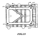
空気は、図1に概略的に示されている吸気カバー部82における吸込路85の吸気口84から、ロータハウジング部90の吸気開口部84A(図21を参照)を通って、ロータ26と28との間を通過し、ハウジングアセンブリ80のロータハウジング部90によって部分的に形成されている排気路88の排気口86(図23に最も示されている)へ、スーパーチャージャーアセンブリ11を横断するように、流れる。ロータハウジング部90は、ロータ26,28及びシャフト30,32を半径方向に包囲する。シャフト30は、ロータハウジング部90の軸方向の一端部から、吸気カバー部82へ延びている。バイパス通路94の一部92は、吸気カバー部82によって形成される。また、このバイパス通路94は、バイパスルートとして適用される。
Air passes through the intake opening 84A (see FIG. 21) of the
バイパスバルブ70は、バイパス通路94内で支持され、また、バイパスバルブ70が図1に示されている閉鎖位置にある場合、バイパス通路94を実質的に閉じる。このバイパスバルブ70の位置は、概略的なものであり、また、バイパス通路94を通過する空気の流れが、バルブ70によって完全に遮断される位置を表していることが、意図されている。バイパスバルブ70は、コントローラ65によって制御され、図1の細線で示されている開放位置70Aに移動することが可能である。バイパスバルブ70が、開放位置70Aにあると、空気は、エンジンの過給が好ましくないような場合にロータ26,28をバイパスして、吸気部84から、バイパス通路94を経由して、スロットルボディ16へ流れることができる。
The
図2及び4は、ロータハウジング部90に取り付けられたギアカバー部95を示しており、このギアカバー部95は、遊星歯車装置41及びギア部材53,54を取り囲む。電動発電機50のモータハウジング部96は、ギアカバー部95に取り付けられている。ギアカバー部95とモータハウジング部96の双方は、固定されたハウジングアセンブリ80の一部である。ハウジングアセンブリ80は、吸込路85に延びる吸気管97を含み、この吸気管97は、吸気カバー部82に取り付けられている。ハウジングアセンブリ80は、さらに、ロータハウジング部90に取り付けられた排気ハウジング99に取り付けられ、排気路88に延びる排気管98を含む。この排気管98は、排気管98に接続された追加の延長管(図示せず)を介して、図1に示されているスロットルボディ16に作動可能に接続されている。
2 and 4 show a
エンジンシリンダ内のピストンの動作は、プレナム18を通過する空気を引き入れ、負圧を作る。スロットル14が、図1に示されるような比較的閉鎖された位置にある場合、エンジン13によって作り出される負圧は、スロットル14にまたがっての圧力降下の形で圧力差を生む。スロットル14が、比較的開放された位置14Aに移動した場合、スロットル14にまたがる圧力降下は、軽減される。しかしながら、電動発電機50を制御することにより、この圧力差は、ロータ26,28に伝達され、ロータ26,28においてトルクを生成し、このトルクを、エネルギ蓄積装置64内の電気エネルギとして回収することができる。
The operation of the piston in the engine cylinder draws air passing through the plenum 18 and creates a negative pressure. When the throttle 14 is in a relatively closed position as shown in FIG. 1, the negative pressure created by the
換言すると、スロットル14が比較的開放された位置14Aにあると、圧力差が、スロットル14への上流の空気の流れにおける、吸気口84から排気口86まで、つまり、スーパーチャージャー12にまたがって作り出される。下記のように、スロットル14及びバイパスバルブ70が、エンジン13と連動して選択的に制御されることが可能である。これにより、スーパーチャージャー12及び電動発電機50が用いられ、エネルギ蓄積装置64に再生用電気エネルギを供給することを可能にしつつ、エンジンシリンダに所望の吸気圧力を供給するなどの様々な運転モードを提供することができる。蓄積された電気エネルギは、電動発電機50がモータとして機能するように制御される場合、交流電源,及び/または,クランクシャフト48によるトルク生成の代わりに、複数の車両電気システム及び装置に動力供給するように用いられることが可能である。
In other words, when the throttle 14 is in the relatively open position 14A, a pressure differential is created across the
スーパーチャージャーアセンブリ11を備えたエンジンアセンブリ10は、様々な運転モードを実現可能にし、この様々な運転モードは、エンジンのトルク要求量のような車両の運転条件やエネルギ蓄積装置64のチャージ状態に基づいて、コントローラ65によって選択され、指定されることが可能である。エンジン13が停止している場合、補機車両部品78に動力供給するために、シャフト61においてトルクを生成するエンジン停止運転モードが用いられてもよい。本発明において用いられるエンジン13は、燃料及び/またはイグニッションが、エンジン13内の燃焼用として供給されない場合、停止している。このエンジン停止運転モードにおいて、コントローラ65は、モータとして電動発電機50を制御し、ブレーキ68を係合し、かつ、クラッチ55の連結を外す。これにより、トルクは、電動発電機50から、遊星歯車装置41を介して、補機部品78に伝達される。
The
車両の運転条件が、エンジン13が起動されるべきであると示した場合、エンジンアセンブリ10は、モータとして機能するように電動発電機50を制御し続けながら、かつ、ブレーキ68の係合を保持しつつクラッチ55を係合することによって、エンジン停止運転モードからエンジン起動運転モードへシンプルに移行されることが可能である。これにより、電動発電機50からのトルクは、クランクシャフト48に伝達され、エンジン13を起動する。
If the vehicle operating conditions indicate that the
一旦エンジンが起動されると、コントローラ65が、エネルギ蓄積装置64から電動発電機50へ電気エネルギを移動させることなく、また、電動発電機50からエネルギ蓄積装置64へ電気エネルギを移動させることもなく、電動発電機50は、惰性で回転することができる。この電動発電機50の起動/停止能力は、エンジン13が、交通信号機などにおいてアイドリングするよりもむしろ停止し、予期される燃費の向上,及び,二酸化炭素排出量の削減をもたらすことを可能にする。従って、燃料節約は、エンジン13が停止している期間に実現され、また、エンジン13の再起動は、バッテリに蓄積された回収エネルギから生成される電気エネルギによって、実現される。
Once the engine is started, the
また、一旦エンジン13が起動されると、電動発電機50は、モータ,発電機のうちどちらでも機能することができる。エンジン13が動作している状態で、後述されるエンジン過給モード,ブレーキ回生モード,及び,スロットルロス回生モードが用いられる。エンジン過給運転モードは、例えば車両を加速させるために追加のトルクが駆動軸21において必要とされた場合、コントローラ65によって実現されることが可能である。
In addition, once the
エンジン13が動作している状態で、この過給運転モードを実現するために、クラッチ55が係合され、かつ、ブレーキ68の連結が外れる。電動発電機50が、モータとして機能し、また、バイパスバルブ70が、図1に示されている閉鎖位置にあるように制御される。エンジン13は、トルクを供給し、ベルト駆動システム49及びキャリア部材46を介して、第1シャフト30を駆動する。電動発電機50は、トルクを供給し、噛み合いギア53,54及びリングギア部材44を介して、第1シャフト30を駆動する。これにより、第1シャフト30の回転速度が、電動発電機50のみを用いたシャフト61の回転速度と比べて、速くなり、リングギア部材44の回転速度を調整し、また、遊星歯車装置41を介して、シャフト56及び30の所望の回転速度を設定し、所望の過給圧力をもたらす。
In order to realize this supercharging operation mode while the
これにより、エンジンのプレナム18に供給される過給圧力量を、トルク要求の変化に応じて、エンジン過給運転モード中に変化させることができる。まず、コントローラ65は、電動発電機50の速度を変化させ、エンジン過給運転モード中にプレナム18内に生成される過給圧力量を制御することができる。これに代えて、または、これに加えて、コントローラ65は、バイパスバルブ70の位置を制御することができ、例えば、図1に示されている閉鎖位置から開放位置70Aへバイパスバルブ70を移動させる。
Thereby, the supercharging pressure amount supplied to the plenum 18 of the engine can be changed during the engine supercharging operation mode in accordance with the change in the torque request. First, the
これにより、吸気口84からの空気は、バイパス通路94を通って流れることができ、ロータハウジング90を経由してロータ26,28を通って流れる空気容量を減らし、これにより、空気がロータ26,28のみを通って流れる場合に生成される圧力と比較して、プレナム18における空気圧を減らす。バイパスバルブ70を完全開放位置70Aに開放するためのバイパスバルブ70の操作は、電動発電機50の速度を変化させることによって実現される、より漸次的な調整と比較して、プレナム18内の空気圧の比較的迅速な調整を可能にする。
This allows air from the
過給圧力がより変化する調整は、バイパスバルブ70を、完全開放位置70Aと完全閉鎖位置との間の中間位置に設置することによって、実現される。電動発電機50の速度とバイパスバルブ70の位置の双方を制御することは、エンジンのトルク要求に合うように調整されるエンジンの過給を可能にする。スーパーチャージャー12によってプレナム18において生成される過給圧力が、エンジン速度に依存しないので、比較的一定のトルクが、エンジン13の動作速度の全体範囲にわたり、クランクシャフト48において得られる。また、クランクシャフト48におけるトルクは、エンジン動作速度の全体範囲にわたり、要求に合うように調整されることが可能である。
Adjustment in which the supercharging pressure changes more is realized by installing the
エンジン13が動作中で、かつ、エンジンの過給が必要とされていない場合、例えば、車両が比較的一定の速度で走行しているとき、コントローラ65は、スーパーチャージャー12の速度を減速させ、また、スロットル14を制御することができ、それにより、スロットルロス(つまり、エンジンシリンダの運動によって作り出される負圧に関連した圧力降下)が、バイパスバルブ70を閉鎖した状態において、スロットル14とスーパーチャージャー12の双方にわたって生じる。
When the
スロットル14の絞り位置は、スーパーチャージャー12を横切る望ましい圧力降下、及び、スーパーチャージャー12と少なくとも部分的に閉鎖されたスロットル14との双方を通って、エンジンシリンダに供給される空気流とバランスすることができる。バイパスバルブ70は、さらに、エンジン13への空気の流れに迅速な変化が必要とされる場合、このモードの間に、空気がスーパーチャージャー12をバイパスするように、制御されることが可能である。スーパーチャージャー12を横切る圧力降下によって生成されるトルクは、サンギア部材42に伝達される。これにより、このトルクは、遊星歯車装置41によって提供されるトルク分割によって、エンジンのクランクシャフト48、さらに、電動発電機50(発電機として動作するように制御された場合に限り)に伝達される。
The throttle position of the throttle 14 balances the desired pressure drop across the
この運転モードは、スロットルロス回生モードということができる。スーパーチャージャー12を横切る圧力降下によって生成されるトルクのすべて,または,一部は、発電機として機能するように電動発電機50を制御することによって、エネルギ蓄積装置64に蓄積される電気エネルギに変換されることが可能である。この圧力降下から誘発されるトルクから生成され、蓄積される電気エネルギは、“スロットルロスの回収”として言及される。
This operation mode can be referred to as a throttle loss regeneration mode. All or part of the torque generated by the pressure drop across the
長い走行期間の間、エンジンの過給が必要とされない場合、このスロットルロス回生モードは、エネルギ蓄積装置64が所定の最大チャージ状態に到達するまで、保持されることが可能である。その後、ブレーキ68が用いられ、バイパスバルブ70が完全開放位置70Aに開放され、また、電動発電機50がモータとして機能するように制御され、エネルギ蓄積装置64が所定の最小チャージ状態に到達するまで、エンジンのクランクシャフト48にトルクを加える。このエネルギ蓄積装置64のチャージと枯渇の循環は、走行期間全体を通して継続することができる。
If no supercharging of the engine is required for a long travel period, this throttle loss regeneration mode can be maintained until the
1つの例として、スーパーチャージャー12を横切る圧力降下は、増分Δだけ増大される。あらゆるエンジン速度においてスーパーチャージャー12を横切って、より大きな圧力降下をもたらすことになる、この増分Δは、圧力差が実質的にゼロになるところまで、圧力降下が減少しないようにする。1つの例として、Δは、少なくとも低エンジン速度に適用される。もう1つの例として、Δは、あらゆるエンジン速度において適用される。このように、持続的なエネルギが、スロットルロス回生によって回収され、燃費に最低限の影響を及ぼすことが可能である。
As one example, the pressure drop across the
このような例において、制御システムは、発電機として機能するように電動発電機50を制御するように構成され、また、スロットルバルブ14は、比較的開放位置よりに移動するように制御され、スーパーチャージャー12を横切る圧力降下が、元の絞り圧力降下と等しいか、または、それより大きくなり、電動発電機50は、遊星歯車装置41を介して、電気エネルギとしてスロットルロスを回収する。
In such an example, the control system is configured to control the
また、スーパーチャージャーアセンブリ11は、ブレーキ回生モードにおいて、車両の制動中にエネルギを回収するように制御されることが可能である。車両の制動が駆動軸21を減速したとき、コントローラ65は、ブレーキ68を係合し、発電機として機能するように電動発電機50を制御するように構成される。これにより、電動発電機50がモータとして機能する場合に、電動発電機50によって供給されるトルクの方向と反対方向になる逆方向のトルクを、電動発電機50に加える。これにより、この逆方向トルクは、遊星歯車装置41を介してクランクシャフト48にかけられ、また、電動発電機50によって生成される電気エネルギは、エネルギ蓄積装置64に蓄積される。
The supercharger assembly 11 can also be controlled to recover energy during braking of the vehicle in the brake regeneration mode. When vehicle braking decelerates the drive shaft 21, the
図1は、プーリシャフト61と共転するようにプーリシャフト61に取り付けられたオイルスリンガ100を示している。図19は、プーリシャフト61から機械的に分離されたオイルスリンガ100の斜視図である。このオイルスリンガ100は、プーリシャフト61の外面に嵌合するように形成された第1内径104を有する第1端部102を備えた環状部材である。第2端部106は、第1端部102より大きい直径を有し、オイルスリンガ100は、プーリシャフト61から第2端部106に向かって拡開する。
FIG. 1 shows an
図3に最もよく示されているように、オイルスリンガ100は、第2端部106が遊星歯車装置41に面するようにプーリシャフト61上に設置される。図19は、オイルスリンガ100の第1端部102と第2端部106との概ね中間における外周に一連の窪み部108が、形成されていることを示している。この窪み部108の各々は、開口部110を有しており、この開口部110の各々は、同一回転方向に面して開口している。各窪み部108は、より大きい端部106とより小さい端部102との間の軸方向においてテーパ状になっている。
As best shown in FIG. 3, the
プーリシャフト61が時計回りの方向に回転する場合、オイルスリンガ100も時計回りに回転し、また、ギアカバー部95内のオイルミストは、開口部110から入り、窪み部108によって取込まれる。オイルミストは、窪み部108の内表面112に接触する。オイルスリンガ100の回転は、オイルミストを、オイルスリンガ100の内面114に沿って第2端部106の方へ移動させ、また、矢印Aの方向にオイルスリンガ100から推進させる。このオイルは、概して、遊星歯車装置41への注油のために、遊星歯車装置41の方へ散布される。
When the
図2は、互いに取り付けられたハウジングアセンブリ80の様々な部品を備えたスーパーチャージャーアセンブリ11を示している。吸気管97は、図18に示されているような吸気カバー部82の開口部113と合致する複数の開口部を有し、ファスナ115を用いて、吸気口84を覆うように吸気管97を吸気カバー部82に取り付ける。ここで用いられるファスナは、2つの隣接する部品を連結するために用いられる、ボルト,ねじ,その他の適切なファスナなどのあらゆる適切な部品である。
FIG. 2 shows the supercharger assembly 11 with various parts of the
図3は、歯付端部118を有する第1シャフト30の延長部116を示している。フランジ122を備えた回転部材120が、歯付端部118にスプライン結合され、また、ベアリング124によって吸気カバー部82に支持されており、これにより、回転部材120は、吸気カバー部82に対して回転可能になっている。延長部116,歯付端部118,回転部材120,及び,フランジ122は、キャビティ69内に配置されている。電磁ブレーキ68は、図18に示されている配線用開口部126を通過して延びるケーブル(図示せず)を経由して、コントローラ65によって選択的に作動可能である。このケーブルは、ブレーキ68内のコイル128を作動させるために用いられる電気エネルギを供給し、ブレーキ68は、電磁吸引によって吸気カバー部82に対して静止するようにフランジ122を保持する。
FIG. 3 shows an
コイル128は、図18ではなく図3に示されている。ブレーキカバー130が、吸気カバー部82における開口部134内に延びるファスナ132によって、吸気カバー部82に取り付けられている。図1に関して前述したように、吸気カバー部82は、さらに、バイパス通路94の一部92を形成している。この一部92は、吸気口84と流体連通し、また、吸気カバー部82内に延びている。
The
バイパス通路94の一部92は、図18において、ブレーキキャビティ69を覆うように、また、吸気カバー部82の底面から延びるように示されている。説明のため、一部92は、図1において、ブレーキ68の上方にのみ示されている。吸気カバー部82内において、一部92のあらゆる適切な幾何学的配置が、用いられてもよい。バイパス通路94は、吸気カバー部82に接続され、一部92に連通している。また、バイパス通路94は、T字形配管または同様のものを用いて、吸気カバー部82及び吸気管97より上流に取り付けられてもよい。
A
図2は、吸気カバー部82をロータハウジング部90に取り付けるために用いられるファスナ135を示している。ここでは1つのファスナ135のみが示されているが、複数の追加のファスナ135が、ロータハウジング部90及び吸気カバー部82の接触部近辺の様々な複数の位置に取り付けられることが可能である。図3は、吸気カバー部82がロータハウジング部90に取り付けられた場合、第1シャフト30が、ロータハウジング部90から吸気カバー部82内へ延びることを示している。
FIG. 2 shows a
図5は、スーパーチャージャーアセンブリ11の一部のより拡大した図であり、この図は、遊星歯車装置41,及び,遊星歯車装置41の第1シャフト30への作動接続を示している。特に、連結部材58は、モータハウジング部96の開口部140内に位置している。連結部材58は、第1部材142を含み、この第1部材142は、第1シャフト30に嵌合され、かつ、周辺に位置する複数のピン146を用いてシャフト56のフランジ144にピン留めされている。連結部材58は、シャフト30を軸にしたスーパーチャージャーアセンブリ11から発生する圧力脈動,または,シャフト61からのエンジン脈動によって引き起こされる可能性がある、ねじり振動を吸収する。シール148は、第1シャフト30をロータハウジング部90に対してシールし、ロータハウジング部90からの空気の漏れを防止する。
FIG. 5 is a more enlarged view of a portion of the supercharger assembly 11, which shows the planetary gear unit 41 and the operative connection of the planetary gear unit 41 to the
図6から8は、複数のファスナ用開口部150のパターンを含むギアカバー部95を示しており、これら開口部150のパターンは、図13に示されているモータカバー部96における複数のファスナ用開口部152のパターンと合致する。ファスナ157(図4において2つ示されている)が、位置合わせした開口部150,152を通ってギアカバー部95をモータハウジング部96に取り付けるように、用いられている。いくつかのファスナ用開口部150が、図6において、ギアカバー部95に取付フランジ154によって覆い隠されている。この取付フランジ154は、複数のファスナ用開口部156を有するが、これらに通す複数のファスナは、ギアカバー部95、これにより、スーパーチャージャーアセンブリ11全体を、図1のエンジン13に取り付けるためにセットされる。
FIGS. 6 to 8 show a
プーリ59が、プーリ59内の開口部を通って延びる六角穴付ねじ158と共に示されており(図4参照)、この六角穴付ねじ158は、プーリ59をプーリシャフト61に取り付ける。このプーリシャフト61は、ギアカバー部95における1つの開口部を通って延びている。ワッシャ161が、六角穴付ねじ158とプーリシャフト61との間に設置されている。図4に示されているベアリング160A,160Bは、プーリシャフト61及びプーリ59が、ギアカバー部95に対して回転することを可能にする。ギアカバー部95を貫通する少なくとも1つの通路162は、潤滑流体を、ギアカバー部95の中を通してベアリング160A,160Bに向ける。
A
シール164が、シャフト61が延びているギアカバー部95内の開口部において、ギアカバー部95とプーリ59との間に設置されている。図7に最も示されているように、波形皿バネ166Aが、プーリ59とベアリング160Aとの間に設置されており、この波形皿バネ166Aは、ベアリング160Aの内輪が、シャフト61に対して回転することを妨げ、また、累積公差に対処する。もう1つの波形皿バネ166Bが、ベアリング160Bとギアカバー部95の突起部との間に設置されており、この波形皿バネ166Bは、ベアリング160Bの外輪が、ギアカバーハウジング95内で回転することを妨げる。
A
皿バネ166C,166Dが、さらに、ギアカバー部95と、モータギア53のシャフト端部,及び,中間ギア54のシャフト端部との間に其々用いられており、これらの皿バネ166C,166Dは、ギアカバー部95の複数の凹部169内に収容された複数のニードルベアリング168A,168Bにかかっている。これらの皿バネ166C,166Dは、摺動面を提供し、また、累積公差に対処する。ニードルベアリング168Aは、ギア53が、モータハウジング部96に対して回転すること、及び、モータハウジング部96内に延びることを可能にする。ギア53は、モータシャフト52にスプライン結合されている(図4参照)。ニードルベアリング168B及び188は、ギア54が、ギアハウジング部95及びモータハウジング部96に対して回転することを可能にする。
The disc springs 166C and 166D are further used between the
図20は、ギアカバー部95が、複数のリブ167A,167B,167Cを有することを示しており、これらのリブ167A,167B,167Cは、戦略的に、オイルを収集し、ギアカバー部95内にオイルを方向付ける。リブ167A及び167Bは、概して、ニードルベアリング168A,168Bが収容されている其々の凹部169の上方にV字形を形成する。ギアカバー部95内の油滴は、リブ167A,167Bにおいて収集され、其々の凹部169にドレーンされ、ベアリング168A,168Bを潤滑する。リブ167Cは、V字形を形成し、戦略的に、ギアカバー部95内のオイルを通路162へ方向付ける。オイルは、通路162を経由して、ベアリング160A,160B間の開口部151内の空間にドレーンされ、ベアリング160A, 160Bを潤滑する。
FIG. 20 shows that the
図9から12は、排気管98を備えた排気ハウジング99を示しており、この排気管98は、排気ハウジング99から延びている。この実施形態において、排気管98と排気ハウジング99は、溶接されている。図21及び22の実施形態において、排気ハウジング99Aと排気管98Aは、単一のワンピースの排気用部品101である。図9の排気ハウジング99は、複数のファスナ用開口部170のパターンを有し、これら開口部170のパターンは、ロータハウジング部90における排気口86の周囲に存在する複数のファスナ用開口部177のパターン(図23参照)と合致する。
FIGS. 9 to 12 show an
排気ハウジング99をロータハウジング部90に接続する1つのファスナ172が、図2に示されている。図9は、開口部174を備えたフランジ173を示しており、この開口部174は、排気ハウジング99をエンジン13に取り付けるために用いられる。排気ハウジング99の開口部103は、ロータハウジング部90の排気口86と流体連通している。排気管98の排気口176は、図1のスロットルボディ16に送り込まれている。
One
図13から15は、開口部182を有する取付フランジ180を備えたモータハウジング部96を示しており、この開口部182によって、モータハウジング部96は、図1のエンジン13に取り付けられることが可能である。この取付フランジ180は、ギアカバー部95のフランジ154と同一方向に延びている。シール185は、モータハウジング部96の開口部186内に設置されており、図4に示されているように、モータシャフト52は、この開口部186内において、第1ギア部材53にスプライン結合されている。
FIGS. 13 to 15 show a
ニードルベアリング188は、モータハウジング部96の他の開口部190内に設置されており、第2ギア部材54は、この開口部190内において、回転支持されている。ロータハウジング部90は、複数の段付開口部192内に延びる複数のファスナを用いて、モータハウジング部96の開口部140の周囲に取り付けられることが可能である。図14は、モータハウジング部96が、フランジの周囲に複数の開口部193を有することを示しており、図4のモータコントローラハウジング194は、この開口部193内に延びる複数のファスナによってモータハウジング部96に取り付けられている。モータハウジング部96は、電動発電機50を冷却するための一体型の冷却フィン196を含む。
The
図16から18は、キャビティ69内に延びる延長部116に歯付端部118を備えた吸気カバー部82を示している。図17は、吸気カバー部82に対して回転するように延長部116を支持しているベアリング198を示している。止め輪200が、吸気カバー部82のボア内において、このベアリング198を保持している。波形皿バネ202が、ベアリング198と吸気カバー部82との間の軸方向スラスト力を吸収し、ベアリング198の外輪が、ボア内で回転することを防止する。段付開口部204が、吸気カバー部82内に延びており、この段付開口部204は、吸気カバー部82が複数のファスナ(図示せず)を用いてロータハウジング部90に取り付けられることを可能にする。
FIGS. 16 to 18 show an
図21及び22は、排気ハウジング99A及び排気管98Aを含む単一のワンピースの排気用部品101を示している。この排気用部品101は、図24のスーパーチャージャーアセンブリ11Aに示されているように、図2のスーパーチャージャーアセンブリ11の排気ハウジング99及び排気管98の代わりに用いられることが可能である。また、スーパーチャージャーアセンブリ11Aのその他の部品は、スーパーチャージャーアセンブリ11と同一である。延長管105が、排気管98Aに溶接され、スロットルボディ16に接続されることが可能である。
21 and 22 show a single one-
排気ハウジング99Aは、概ね五角形に形作られる開口部103Aを有する。この開口部103Aは、より幅の広い端部に向かい合って、テーパ状のV字形端部を有する。図23は、ロータハウジング部90の排気口86が、同様に、概ね五角形に形作られ、開口部103Aと概ね同一の形状であることを示している。排気管98Aは、排気ハウジング99Aから45度の角度で延びている。これら、開口部103Aの概ね五角形形状、及び、排気ハウジング99Aから延びている排気管98Aの角度は、有益な気流特性を提供する。図24は、スーパーチャージャーアセンブリ11Aを示しており、このスーパーチャージャーアセンブリ11Aは、排気ハウジング99及び排気管98の代わりに排気用部品101を含むハウジングアセンブリ80Aを備えていること以外は、図2のスーパーチャージャーアセンブリ11と同様である。
The
図1及び2から明らかなように、ハウジングアセンブリ80は、電動発電機50及びロータハウジング部90が、プーリ59に対してギアカバー部95の反対側に存在するように構成されている。さらに、吸込路85及び吸気管97は、電動発電機50に隣接しており、また、排気路88及び排気管98は、電動発電機50に対してロータハウジング部90の反対側に存在する。ハウジングアセンブリ80Aも同様に配置される。当然のことながら、スロットルボディ16及びスロットル14は、エンジン13に空気を流す吸気管97の上流に配置されてもよく、この場合、スーパーチャージャー12は、スロットル14から空気を取込み、また、本明細書内で説明した同一の複数の運転モードを使用可能にするであろう。
As is apparent from FIGS. 1 and 2, the
本教示における多くの様態を実施するための最良の形態を詳細に記載した一方で、これらの教示に関連する当業者は、添付の請求の範囲内に存在する本教示を実施するための様々な代替の様態を認識するであろう。 While the best mode for carrying out many aspects of the present teachings has been described in detail, those skilled in the art to which these teachings pertain will provide various information for implementing the present teachings that are within the scope of the appended claims. You will recognize alternative aspects.
図面に用いられる符号,及び,符号に対応する部品の指定は、以下の通りである。
10…エンジンアセンブリ、 11,11A…スーパーチャージャーアセンブリ、
12…スーパーチャージャー、 13…エンジン、 14…スロットル、
14A…スロットルの完全開放位置、 16…スロットルボディ、 18…プレナム、
20…吸気マニホールド、 21…駆動軸、 22…トランスミッション、
24…一組のロータ、 26…第1ロータ、 28…第2ロータ、 30…第1シャフト、
31…第1の一組のプレート、 32…第2シャフト、 33…第2の一組のプレート、
34…第1ギア、 35…クラッチハウジング、 36…第2ギア、 37…スプリング、
38…アプライプレート、 39…コイル、 41…遊星歯車装置、 42…サンギア部材、
44…リングギア部材、 46…キャリア部材、 47…ピニオンギア、
48…クランクシャフト、 49…ベルト駆動装置、 50…電動発電機、
52…モータシャフト、 53…第1ギア部材、 54…第2ギア部材、 55…クラッチ、
56…シャフト、 57…プーリ、 58…部分的に柔軟な連結部材、 59…プーリ、
61…プーリシャフト、 62…モータ制御装置、 63…ベルト、
64…エネルギ蓄積装置、 65…システムコントローラ、 66…電力ケーブル、
68…ブレーキ、 69…キャビティ、 70…バイパスバルブ、
70A…バイパスバルブの完全開放位置、 76…プーリ、 78…車両補機、
79…シャフト、 80,80A…固定されたハウジングアセンブリ、 82…吸気カバー部、
84…吸気カバー部の吸気口、 84A…ロータハウジング部の吸気開口部、
85…吸込路、 86…排気口、 88…排気路、 90…ロータハウジング部、
92…バイパス通路の一部、 94…バイパス通路、 95…ギアカバー部、
96…モータハウジング部、 97…吸気管、 98,98A…排気管、
99,99A…排気ハウジング、 100…オイルスリンガ、 101…排気用部品、
102…オイルスリンガの第1端部、 103…排気ハウジング99の開口部、
103A…排気ハウジング99Aの開口部、 104…第1内径、 105…延長管、
106…オイルスリンガの第2端部、 108…窪み部、 110…開口部、
112…窪み部の内表面、 113…吸気カバー部の開口部、
114…オイルスリンガの内面、 115…ファスナ、 116…第1シャフトの延長部、
118…歯付端部、 120…回転部材、 122…フランジ、 124…ベアリング、
126…配線用開口部、 128…コイル、 130…ブレーキカバー、
132…ファスナ、 134…開口部、 135…ファスナ、
140…モータハウジング部の開口部、 142…連結部材の第1部材、
144…シャフト56のフランジ、 146…ピン、 148…第1シャフトのシール、
150…ギアカバー部におけるファスナ用開口部、 151…開口部、
152…モータカバー部におけるファスナ用開口部、 154…取付フランジ、
156…ファスナ用開口部、 157…ファスナ、 158…六角穴付ねじ、
160A,160B…ベアリング、 161…ワッシャ、 162…通路、 164…シール、
166A,166B…波形皿バネ、 166C,166D…皿バネ、 167A,167B,167C…リブ、
168A,168B…ニードルベアリング、 169…凹部、 170…ファスナ用開口部、
172…ファスナ、 173…フランジ、 174…開口部、 176…排気管の排気口、
177…ファスナ用開口部、 180…取付フランジ、 182…開口部、 185…シール、
186…開口部、 188…ニードルベアリング、 190…開口部、 192…段付開口部、
193…開口部、 194…モータコントロールハウジング、 196…冷却フィン、
198…ベアリング、 200…止め輪、 202…波形皿バネ、 204…段付開口部、
A…オイルの方向
The symbols used in the drawings and the designation of parts corresponding to the symbols are as follows.
10 ... Engine assembly 11,11A ... Supercharger assembly,
12 ... Supercharger, 13 ... Engine, 14 ... Throttle,
14A ... Full throttle position, 16 ... Throttle body, 18 ... Plenum,
20 ... intake manifold, 21 ... drive shaft, 22 ... transmission,
24 ... a set of rotors, 26 ... first rotor, 28 ... second rotor, 30 ... first shaft,
31 ... first set of plates, 32 ... second shaft, 33 ... second set of plates,
34 ... first gear, 35 ... clutch housing, 36 ... second gear, 37 ... spring,
38 ... apply plate, 39 ... coil, 41 ... planet gear, 42 ... sun gear member,
44 ... Ring gear member, 46 ... Carrier member, 47 ... Pinion gear,
48 ... Crankshaft, 49 ... Belt drive, 50 ... Motor generator,
52 ... motor shaft, 53 ... first gear member, 54 ... second gear member, 55 ... clutch,
56 ...
61 ... pulley shaft, 62 ... motor controller, 63 ... belt,
64… Energy storage device, 65… System controller, 66… Power cable,
68 ... brake, 69 ... cavity, 70 ... bypass valve,
70A ... Fully open position of bypass valve, 76 ... Pulley, 78 ... Vehicle accessory,
79 ... Shaft, 80,80A ... Fixed housing assembly, 82 ... Air intake cover,
84: Intake port of the intake cover part, 84A ... Intake opening part of the rotor housing part,
85 ... Suction passage, 86 ... Exhaust port, 88 ... Exhaust passage, 90 ... Rotor housing part,
92 ... Part of bypass passage, 94 ... Bypass passage, 95 ... Gear cover,
96 ... motor housing, 97 ... intake pipe, 98,98A ... exhaust pipe,
99,99A… Exhaust housing, 100… Oil slinger, 101… Exhaust parts,
102: First end of oil slinger 103: Opening of
103A ... Opening of
106 ... second end of oil slinger, 108 ... dent, 110 ... opening,
112 ... the inner surface of the recess, 113 ... the opening of the air intake cover,
114 ... Inner surface of oil slinger, 115 ... Fastener, 116 ... Extension of first shaft,
118 ... Toothed end, 120 ... Rotary member, 122 ... Flange, 124 ... Bearing,
126 ... opening for wiring, 128 ... coil, 130 ... brake cover,
132 ... Fastener, 134 ... Opening, 135 ... Fastener,
140: opening of motor housing part, 142: first member of connecting member,
144 ... flange of
150 ... opening for fastener in gear cover, 151 ... opening,
152 ... Opening for fastener in motor cover, 154 ... Mounting flange,
156 ... Opening for fastener, 157 ... Fastener, 158 ... Hexagon socket head screw,
160A, 160B ... bearings, 161 ... washers, 162 ... passages, 164 ... seals,
166A, 166B ... Wavy disc spring, 166C, 166D ... Belleville spring, 167A, 167B, 167C ... Rib,
168A, 168B… needle bearing, 169… recess, 170… fastener opening,
172 ... Fastener, 173 ... Flange, 174 ... Opening, 176 ... Exhaust port of exhaust pipe,
177 ... Opening for fastener, 180 ... Mounting flange, 182 ... Opening, 185 ... Seal,
186 ... opening, 188 ... needle bearing, 190 ... opening, 192 ... stepped opening,
193 ... opening, 194 ... motor control housing, 196 ... cooling fin,
198 ... Bearing, 200 ... Retaining ring, 202 ... Corrugated disc spring, 204 ... Stepped opening,
A ... Oil direction
Claims (20)
前記プレナムの上流から前記エンジンに空気を流し、第1シャフトに共転するように取り付けられた第1ロータ,及び,前記第1ロータと噛み合い、前記第1シャフトの回転によって第2シャフトに共転するように取り付けられた第2ロータを有する、スーパーチャージャーと、
モータ及び発電機として選択的に動作可能な電動発電機と、
該電動発電機によって回転するように動作可能に連結される第1部材,前記エンジンのクランクシャフトによって回転するように連結可能な第2部材,及び,前記第1シャフトと共転するように動作可能に連結される第3部材を有する、遊星歯車装置と、
前記エンジンのクランクシャフトと共転するように前記第2部材を動作可能に連結するための選択的に係合可能なクラッチ,及び,前記第1シャフトの固定を保持するための選択的に係合可能なブレーキを含む、2つの選択的に係合可能なトルク伝達機構と、
前記電動発電機,前記ブレーキ,及び前記クラッチを制御し、複数の異なる運転モードを実現するように構成される制御システムと、
を含むことを特徴とするスーパーチャージャーアセンブリ。 A supercharger assembly for an engine having a crankshaft and an intake manifold forming a plenum, wherein air flow is supplied to the engine via the plenum,
Air flows from the upstream side of the plenum to the engine and meshes with the first rotor that is attached to the first shaft and the first shaft. The first rotor rotates and rotates to the second shaft. A supercharger having a second rotor mounted to
A motor generator capable of selectively operating as a motor and a generator;
A first member operably connected to rotate by the motor generator, a second member connectable to rotate by a crankshaft of the engine, and operable to rotate with the first shaft A planetary gear device having a third member coupled to
A selectively engageable clutch for operably connecting the second member for rotation with the crankshaft of the engine, and a selectively engaged for holding the first shaft fixed Two selectively engageable torque transmission mechanisms including possible brakes;
A control system configured to control the motor generator, the brake, and the clutch to achieve a plurality of different operation modes;
A supercharger assembly characterized by comprising:
前記第1及び第2ロータをバイパスして、空気が前記スーパーチャージャーの吸気口から前記プレナムへ流れることを可能にするように構成されるバイパス通路と、
前記バイパス通路を通過する空気流を制御するように作動可能なバイパスバルブと、
を含み、
前記制御システムは、前記エンジン過給運転モードの間に、前記バイパスバルブの位置を制御し、エンジントルク要求の変化に従って前記プレナム内の空気圧を調整するように構成されることを特徴とする請求項4に記載のスーパーチャージャーアセンブリ。 The supercharger assembly further includes:
A bypass passage configured to bypass the first and second rotors and allow air to flow from the supercharger inlet to the plenum;
A bypass valve operable to control airflow through the bypass passage;
Including
The control system is configured to control the position of the bypass valve and adjust the air pressure in the plenum according to changes in engine torque demand during the engine supercharging mode. 5. The supercharger assembly according to 4.
前記スーパーチャージャーは、空気を前記エンジンに流す前記スロットルバルブと直列に配置され、また、
前記電動発電機に作動可能に接続されるエネルギ蓄積装置をさらに含み、前記エネルギ蓄積装置は、前記電動発電機がモータとして機能している場合、前記電動発電機に電気エネルギを供給し、また、前記電動発電機が発電機として機能している場合、前記電動発電機から電気エネルギを受け取り、
前記制御システムは、発電機として機能するように前記電動発電機を制御し、また、前記スロットルバルブを比較的開放された位置に移動させるように構成され、それにより、前記スーパーチャージャーを横切る絞り圧力降下によって生成されるトルクが、前記スーパーチャージャーから、前記遊星歯車装置を介して、前記電動発電機へ提供され、これにより、スロットルロスが、電気エネルギとして前記エネルギ蓄積装置内に回収されることを特徴とする請求項1に記載のスーパーチャージャーアセンブリ。 The engine has a throttle body and a throttle valve in the throttle body, and the plenum is configured so that air flows from the downstream of the throttle body to the engine,
The supercharger is disposed in series with the throttle valve for flowing air to the engine, and
An energy storage device operably connected to the motor generator, wherein the energy storage device supplies electrical energy to the motor generator when the motor generator functions as a motor; If the motor generator is functioning as a generator, it receives electrical energy from the motor generator,
The control system is configured to control the motor generator to function as a generator and to move the throttle valve to a relatively open position, thereby reducing the throttle pressure across the supercharger. Torque generated by the descent is provided from the supercharger to the motor generator via the planetary gear unit, so that throttle loss is recovered as electrical energy in the energy storage device. The supercharger assembly according to claim 1, wherein:
前記制御システムは、その後、発電機として機能するように前記電動発電機を制御し、前記スロットルバルブを、比較的開放された位置に移動させるように構成され、それにより、前記スーパーチャージャーを横切る絞り圧力降下によって生成されるトルクが、前記スーパーチャージャーから、前記遊星歯車装置を介して、前記電動発電機へ提供されることを特徴とする請求項7に記載のスーパーチャージャーアセンブリ。 When the charge state of the energy storage device reaches a predetermined maximum value, the control system controls the motor generator to function as a motor instead, engages the brake, and opens the bypass valve And the throttle valve is arranged in a relatively closed position to manage the throttle pressure drop, so that the motor generator has the charge state of the energy storage device at a predetermined minimum value. Drive the crankshaft until it reaches,
The control system is then configured to control the motor generator to function as a generator and move the throttle valve to a relatively open position, thereby restricting the throttle across the supercharger. The supercharger assembly according to claim 7, wherein torque generated by pressure drop is provided from the supercharger to the motor generator via the planetary gear set.
前記第1及び第2ロータを半径方向に包囲するように構成されるロータハウジング部と、
該ロータハウジング部に取り付けるように構成される吸気カバー部と、
を有し、
前記第1シャフトは、前記ロータハウジング部内から前記吸気カバー部内へ延び、かつ、前記吸気カバー部によって支持されており、前記吸気カバー部は、吸込路の少なくとも一部を形成し、空気が、前記吸込路を経由して前記第1及び第2ロータへ供給され、また、前記吸気カバー部は、さらに、キャビティを形成し、前記キャビティ内で前記ブレーキを支持することを特徴とする請求項1に記載のスーパーチャージャーアセンブリ。 The supercharger assembly further includes a housing assembly, the housing assembly comprising:
A rotor housing portion configured to radially surround the first and second rotors;
An intake cover portion configured to be attached to the rotor housing portion;
Have
The first shaft extends from the rotor housing portion into the intake cover portion, and is supported by the intake cover portion. The intake cover portion forms at least a part of a suction passage, and air is 2. The fuel supply device according to claim 1, wherein the suction cover portion is further supplied to the first and second rotors via a suction passage, and the intake cover portion further forms a cavity and supports the brake in the cavity. The described supercharger assembly.
前記バイパス通路内に配置され、また、前記バイパス通路を通過する空気流を制御するように作動可能なバイパスバルブと、
を形成することを特徴とする請求項10に記載のスーパーチャージャーアセンブリ。 The intake cover portion bypasses the first and second rotors, and a part of a bypass passage configured to divert air from the suction passage to the throttle body;
A bypass valve disposed within the bypass passage and operable to control air flow through the bypass passage;
The supercharger assembly of claim 10, wherein:
前記第3部材を前記第1シャフトに動作可能に連結する連結部材と、
ハウジングアセンブリと、
を含み、前記ハウジングアセンブリは、
前記第1及び第2ロータを半径方向に包囲するように構成されるロータハウジング部と、
該ロータハウジングの一端部と位置合わせされた1つの開口部を有するモータハウジング部と、
該モータハウジング部に取り付けられるギアカバー部と、
を有し、
前記第1シャフトは、前記ロータハウジング部内から、前記モータハウジング部内の前記開口部内に配置される前記連結部材へ延び、また、前記ギアカバー部は、前記遊星歯車装置を収容するように構成されることを特徴とする請求項1に記載のスーパーチャージャーアセンブリ。 The supercharger assembly further includes:
A connecting member operably connecting the third member to the first shaft;
A housing assembly;
The housing assembly comprises:
A rotor housing portion configured to radially surround the first and second rotors;
A motor housing portion having one opening aligned with one end of the rotor housing;
A gear cover portion attached to the motor housing portion;
Have
The first shaft extends from the rotor housing portion to the connecting member disposed in the opening in the motor housing portion, and the gear cover portion is configured to accommodate the planetary gear device. The supercharger assembly according to claim 1.
前記スーパーチャージャーアセンブリは、さらに、前記ギアカバー部内に配置され、かつ、前記電動発電機と共転するように連結される第1ギア部材,及び,前記遊星歯車装置の前記第1部材と共転するように連結される第2ギア部材を有するギアトレーンを含み、
これにより、前記ギアトレーンは、前記遊星歯車装置と前記電動発電機との間でトルクを伝達することを特徴とする請求項12に記載のスーパーチャージャーアセンブリ。 The motor housing portion is configured to be attached to the motor generator,
The supercharger assembly is further disposed in the gear cover portion, and is coupled with the first member of the planetary gear device, and a first gear member that is coupled to rotate with the motor generator. A gear train having a second gear member coupled to
The supercharger assembly according to claim 12, wherein the gear train transmits torque between the planetary gear device and the motor generator.
前記プーリシャフトに取り付けられ、前記遊星歯車装置に向かって開口し、かつ、前記ギアカバー部内の流体を前記遊星歯車装置に方向付けるように構成されるオイルスリンガと、
をさらに含むことを特徴とする請求項12に記載のスーパーチャージャーアセンブリ。 A pulley shaft supported by the gear cover portion and coupled to rotate together with the second member, and a pulley operatively coupled to the crankshaft;
An oil slinger attached to the pulley shaft, opening toward the planetary gear device and configured to direct fluid in the gear cover portion to the planetary gear device;
The supercharger assembly of claim 12, further comprising:
プーリシャフトを有するプーリと、
前記ギアカバー部に対して回転するように前記プーリシャフトを支持する複数のベアリングと、
をさらに含み、
前記プーリシャフトは、前記第2部材と共転するように連結され、前記プーリは、前記クランクシャフトに動作可能に連結することができ、
前記ギアカバー部は、一体型の複数のリブ及び通路を有し、前記複数のリブは、潤滑油を収集し、また、前記潤滑油を、前記通路を経由して前記複数のベアリングに方向付けるように配置されることを特徴とする請求項1に記載のスーパーチャージャーアセンブリ。 A gear cover portion configured to accommodate the planetary gear device;
A pulley having a pulley shaft;
A plurality of bearings for supporting the pulley shaft to rotate relative to the gear cover portion;
Further including
The pulley shaft is connected to rotate with the second member, and the pulley can be operably connected to the crankshaft;
The gear cover portion has a plurality of integral ribs and passages, the plurality of ribs collecting lubricating oil and directing the lubricating oil to the plurality of bearings via the passages. The supercharger assembly according to claim 1, wherein the supercharger assembly is arranged as follows.
1つの排気用開口部を含む排気用部品と、
をさらに含み、
前記排気用部品は、前記排気用開口部が前記排気口に流体連通して、前記ロータハウジング部に取り付けられるように構成され、また、前記排気口と前記排気用開口部の双方は、概ね同一の五角形の形状を有することを特徴とする請求項1に記載のスーパーチャージャーアセンブリ。 A rotor housing portion configured to radially surround the first and second rotors and to at least partially form an air inlet and an air outlet;
An exhaust part including one exhaust opening;
Further including
The exhaust component is configured such that the exhaust opening is in fluid communication with the exhaust port and is attached to the rotor housing portion, and both the exhaust port and the exhaust opening are substantially the same. The supercharger assembly according to claim 1, having a pentagonal shape.
空気を前記エンジンに流す前記プレナムと直列に配置され、第1シャフトに共転するように取り付けられた第1ロータ,及び,前記第1ロータと噛み合い、前記第1シャフトの回転によって第2シャフトに共転するように取り付けられた第2ロータを有する、スーパーチャージャーと、
吸気口をスロットルボディに作動可能に接続するバイパス通路と、
該バイパス通路内に配置され、空気が、前記バイパス通路を経由して、前記吸気口と前記スロットルボディとの間を流れることを選択的に可能し、前記第1及び第2ロータをバイパスする、バイパスバルブと、
モータと発電機のどちらか一方として、選択的に動作可能な電動発電機と、
該電動発電機がモータとして機能している場合、前記電動発電機に電気エネルギを供給し、また、前記電動発電機が発電機として機能している場合、前記電動発電機から電気エネルギを受け取るように、前記電動発電機に作動可能に接続される、エネルギ蓄積装置と、
前記電動発電機によって回転するように動作可能に連結される第1部材,第2部材,及び,前記第1シャフトと共転するように動作可能に連結される第3部材を有する、遊星歯車装置と、
クランクシャフトに動作可能に連結されるように構成され、かつ、前記第2部材と共転するように連結されるプーリシャフトを有する、プーリと、
前記電動発電機と共転するように連結される第1ギア部材,及び,前記遊星歯車装置の前記第3部材と共転するように連結される第2ギア部材を有し、これにより、前記遊星歯車装置と前記電動発電機との間でトルクを伝達する、ギアトレーンと、
前記エンジンのクランクシャフトと共転するように前記第2部材を動作可能に連結するための選択的に係合可能な電磁クラッチ,及び,前記第1シャフトの固定を保持するための選択的に係合可能な電磁ブレーキを含む、2つの選択的に係合可能なトルク伝達機構と、
前記電動発電機,前記バイパスバルブ,前記ブレーキ,及び,前記クラッチを制御し、複数の異なる運転モードを実現するように構成される制御システムと、
を含むことを特徴とするスーパーチャージャーアセンブリ。 A supercharger for an engine that forms a plenum and air flows to the engine via the plenum,
A first rotor disposed in series with the plenum for flowing air to the engine and attached to the first shaft for rotation, meshed with the first rotor, and rotated to the second shaft by the rotation of the first shaft. A supercharger having a second rotor mounted for co-rotation;
A bypass passage operatively connecting the intake port to the throttle body;
Disposed in the bypass passage, selectively allowing air to flow between the inlet and the throttle body via the bypass passage, bypassing the first and second rotors; A bypass valve;
A motor generator that can selectively operate as either a motor or a generator;
When the motor generator functions as a motor, it supplies electric energy to the motor generator, and when the motor generator functions as a generator, receives electric energy from the motor generator. An energy storage device operably connected to the motor generator;
A planetary gear device having a first member operably connected to rotate by the motor generator, a second member, and a third member operably connected to rotate with the first shaft. When,
A pulley configured to be operably coupled to a crankshaft and having a pulley shaft coupled to co-rotate with the second member;
A first gear member coupled to rotate together with the motor generator, and a second gear member coupled to rotate together with the third member of the planetary gear device. A gear train for transmitting torque between the planetary gear device and the motor generator;
A selectively engageable electromagnetic clutch for operably connecting the second member for rotation with a crankshaft of the engine, and a selective engagement for holding the first shaft fixed; Two selectively engageable torque transmission mechanisms, including engageable electromagnetic brakes;
A control system configured to control the motor generator, the bypass valve, the brake, and the clutch to achieve a plurality of different operation modes;
A supercharger assembly characterized by comprising:
ハウジングアセンブリを含み、前記ハウジングアセンブリは、
前記第1及び第2ロータを半径方向に包囲するように構成され、かつ、吸気開口部,及び,排気路を少なくとも部分的に形成する排気口を有する、ロータハウジング部と、
該ロータハウジング部に取り付けるように構成される吸気カバー部と、
前記ロータハウジング内の前記第1及び第2シャフトと位置合わせされた1つの開口部を有し、前記電動発電機を支持するように構成される、モータハウジング部と、
該モータハウジング部に取り付けられるギアカバー部と、
を有し、
前記第1シャフトは、前記吸気カバー部内へ延び、かつ、前記吸気カバー部によって支持され、前記吸気カバー部は、吸込路の少なくとも一部を形成し、空気が、前記吸込路を経由して前記ロータハウジング部の前記吸気開口部へ供給され、
前記モータハウジング部内の前記開口部内に連結部材が配置され、前記第1シャフトは、前記連結部材によって前記第3部材に動作可能に連結され、前記ギアカバー部は、前記遊星歯車装置を収容し、かつ、前記プーリ及び前記プーリシャフトを支持するように構成され、
前記ハウジングアセンブリは、前記電動発電機及び前記ロータハウジング部が、前記プーリに対して前記ギアカバー部の反対側に存在し、前記吸込路が、前記電動発電機に隣接しており、また、前記排気路が、前記電動発電機に対して前記ロータハウジング部の反対側に存在するように構成されることを特徴とする請求項17に記載のスーパーチャージャーアセンブリ。 The supercharger assembly further includes:
Including a housing assembly, the housing assembly comprising:
A rotor housing portion configured to radially surround the first and second rotors and having an intake opening and an exhaust port at least partially forming an exhaust passage;
An intake cover portion configured to be attached to the rotor housing portion;
A motor housing portion having one opening aligned with the first and second shafts in the rotor housing and configured to support the motor generator;
A gear cover portion attached to the motor housing portion;
Have
The first shaft extends into the air intake cover portion and is supported by the air intake cover portion, the air intake cover portion forms at least a part of a suction passage, and air passes through the suction passage and passes through the suction passage. Supplied to the intake opening of the rotor housing part,
A connecting member is disposed in the opening in the motor housing portion, the first shaft is operably connected to the third member by the connecting member, and the gear cover portion houses the planetary gear device, And configured to support the pulley and the pulley shaft,
In the housing assembly, the motor generator and the rotor housing part are on the opposite side of the gear cover part with respect to the pulley, the suction path is adjacent to the motor generator, and The supercharger assembly according to claim 17, wherein an exhaust passage is configured to exist on an opposite side of the rotor housing portion with respect to the motor generator.
前記スロットルボディの上流から前記エンジンに空気を流す前記スロットルバルブと直列に配置され、第1シャフトに共転するように取り付けられた第1ロータ,及び,前記第1ロータと噛み合い、前記第1シャフトの回転によって第2シャフトに共転するように取り付けられた第2ロータを有する、ルーツ式スーパーチャージャーと、
該スーパーチャージャーに吸気口を形成するハウジングアセンブリと、
前記吸気口を前記スロットルボディに作動可能に接続するバイパス通路と、
該バイパス通路内に配置され、空気が、前記バイパス通路を経由して、前記吸気口と前記スロットルボディとの間を流れることを選択的に可能し、前記第1及び第2ロータをバイパスする、バイパスバルブと、
モータと発電機のどちらか一方として、選択的に動作可能な電動発電機と、
該電動発電機がモータとして機能している場合、前記電動発電機に電気エネルギを供給し、また、前記電動発電機が発電機として機能している場合、前記電動発電機から電気エネルギを受け取るように、前記電動発電機に作動可能に接続される、エネルギ蓄積装置と、
前記電動発電機によって回転するように連結される第1部材,前記エンジンのクランクシャフトによって回転するように連結可能な第2部材,及び,前記第1シャフトと共転するように連結される第3部材を有する、遊星歯車装置と、
前記エンジンのクランクシャフトと共転するように前記第2部材を動作可能に連結するための選択的に係合可能なクラッチ,及び,前記第1シャフトの固定を保持するための選択的に係合可能なブレーキを含む、2つのみの選択的に係合可能なトルク伝達機構と、
前記電動発電機,前記スロットルバルブ,前記バイパスバルブ,前記ブレーキ,及び,前記クラッチを制御し、前記電動発電機が前記エンジンを起動する運転モード,前記エンジンが動作中であり、また、前記電動発電機が、前記遊星歯車装置を介して前記第1及び第2ロータの速度を変化させ、前記プレナム内の空気圧を調整する運転モード,及び,前記エンジンに流れる空気が、前記バイパス通路を経由して前記第1及び第2ロータをバイパスする運転モードを実現するように構成される制御システムと、
を含むことを特徴とするスーパーチャージャーアセンブリ。 A crankshaft, a throttle body, an intake manifold that forms a plenum downstream of the throttle body, and a throttle valve that is disposed in the throttle body and is selectively adjustable, and adjusts the air flow to the engine; A supercharger for the engine,
A first rotor arranged in series with the throttle valve for flowing air from the upstream of the throttle body to the engine, and attached to the first shaft so as to co-rotate with the first shaft; and meshing with the first rotor; A roots-type supercharger having a second rotor mounted to co-rotate with the second shaft by rotation of
A housing assembly forming an inlet in the supercharger;
A bypass passage operatively connecting the inlet to the throttle body;
Disposed in the bypass passage, selectively allowing air to flow between the inlet and the throttle body via the bypass passage, bypassing the first and second rotors; A bypass valve;
A motor generator that can selectively operate as either a motor or a generator;
When the motor generator functions as a motor, it supplies electric energy to the motor generator, and when the motor generator functions as a generator, receives electric energy from the motor generator. An energy storage device operably connected to the motor generator;
A first member connected to rotate by the motor generator; a second member connectable to rotate by a crankshaft of the engine; and a third member connected to rotate together with the first shaft. A planetary gear device having a member;
A selectively engageable clutch for operably connecting the second member for rotation with the crankshaft of the engine, and a selectively engaged for holding the first shaft fixed Only two selectively engageable torque transmission mechanisms including possible brakes;
An operation mode in which the motor generator, the throttle valve, the bypass valve, the brake, and the clutch are controlled and the motor generator starts the engine; the engine is in operation; and the motor generator An operation mode in which the machine changes the speed of the first and second rotors via the planetary gear device to adjust the air pressure in the plenum, and the air flowing to the engine passes through the bypass passage A control system configured to implement an operating mode that bypasses the first and second rotors;
A supercharger assembly characterized by comprising:
前記制御システムは、発電機として機能するように前記電動発電機を制御するように構成され、また、前記スロットルバルブは、比較的開放された位置に移動するように制御され、それにより、前記スーパーチャージャーを横切る絞り圧力降下が、元の絞り圧力降下と等しいか,または,より大きくなり、これにより、前記電動発電機は、前記遊星歯車装置を介して、この絞り圧力降下を電気エネルギとして回収することを特徴とする請求項19に記載のスーパーチャージャーアセンブリ。 The control system is configured to control the motor generator to function as a generator, and the throttle valve is controlled to move to a relatively open position, whereby the super Torque generated by the throttle pressure drop across the charger is provided from the supercharger via the planetary gear set to the motor generator, thereby recovering throttle loss as electrical energy,
The control system is configured to control the motor generator to function as a generator, and the throttle valve is controlled to move to a relatively open position, whereby the super The throttle pressure drop across the charger is equal to or greater than the original throttle pressure drop, so that the motor generator recovers this throttle pressure drop as electrical energy via the planetary gear set. The supercharger assembly of claim 19.
Applications Claiming Priority (3)
| Application Number | Priority Date | Filing Date | Title |
|---|---|---|---|
| US201261617152P | 2012-03-29 | 2012-03-29 | |
| US61/617,152 | 2012-03-29 | ||
| PCT/US2013/030944 WO2013148205A1 (en) | 2012-03-29 | 2013-03-13 | Variable speed hybrid electric supercharger assembly and method of control of vehicle having same |
Publications (2)
| Publication Number | Publication Date |
|---|---|
| JP2015518537A JP2015518537A (en) | 2015-07-02 |
| JP6185555B2 true JP6185555B2 (en) | 2017-08-23 |
Family
ID=48045709
Family Applications (2)
| Application Number | Title | Priority Date | Filing Date |
|---|---|---|---|
| JP2015503277A Expired - Fee Related JP6185555B2 (en) | 2012-03-29 | 2013-03-13 | Variable speed hybrid electric supercharger assembly and vehicle control method having the same |
| JP2015503278A Pending JP2015514624A (en) | 2012-03-29 | 2013-03-13 | Electric energy generation using a variable speed hybrid electric supercharger assembly |
Family Applications After (1)
| Application Number | Title | Priority Date | Filing Date |
|---|---|---|---|
| JP2015503278A Pending JP2015514624A (en) | 2012-03-29 | 2013-03-13 | Electric energy generation using a variable speed hybrid electric supercharger assembly |
Country Status (8)
| Country | Link |
|---|---|
| US (2) | US20150066272A1 (en) |
| EP (3) | EP2831388B1 (en) |
| JP (2) | JP6185555B2 (en) |
| KR (2) | KR20140136992A (en) |
| CN (4) | CN103358919B (en) |
| IN (1) | IN2014DN07571A (en) |
| RU (1) | RU2014143461A (en) |
| WO (2) | WO2013148206A2 (en) |
Families Citing this family (50)
| Publication number | Priority date | Publication date | Assignee | Title |
|---|---|---|---|---|
| US9086012B2 (en) * | 2010-08-13 | 2015-07-21 | Eaton Corporation | Supercharger coupling |
| WO2012162630A2 (en) | 2011-05-25 | 2012-11-29 | Eaton Corporation | Supercharger-based twin charging system for an engine |
| US9567922B2 (en) | 2011-07-07 | 2017-02-14 | Kasi Technologies Ab | Hybrid system comprising a supercharging system and method for operation |
| WO2013049438A2 (en) | 2011-09-30 | 2013-04-04 | Eaton Corporation | Supercharger assembly with independent superchargers and motor/generator |
| US9074524B2 (en) * | 2011-12-09 | 2015-07-07 | Eaton Corporation | Air supply system with two-stage roots blower |
| USD728625S1 (en) | 2012-03-29 | 2015-05-05 | Eaton Corporation | Hybrid electric supercharger assembly |
| JP6185555B2 (en) * | 2012-03-29 | 2017-08-23 | イートン コーポレーションEaton Corporation | Variable speed hybrid electric supercharger assembly and vehicle control method having the same |
| WO2014042891A1 (en) * | 2012-09-14 | 2014-03-20 | Eaton Corporation | Control system for vehicle drive system having supercharger and accessories |
| EP3674123A3 (en) | 2013-03-12 | 2020-12-09 | Eaton Corporation | Adaptive state of charge regulation and control of variable speed hybrid electric supercharger assembly for efficient vehicle operation |
| EP2969622A2 (en) * | 2013-03-15 | 2016-01-20 | Eaton Corporation | Dual ratio drive for variable speed hybrid electric supercharger assembly |
| WO2015066060A1 (en) | 2013-10-28 | 2015-05-07 | Eaton Corporation | Boost system including turbo and hybrid drive supercharger |
| EP2886824B1 (en) * | 2013-12-20 | 2016-07-20 | FPT Motorenforschung AG | Improved turbocompound scheme, in particular in the field of industrial vehicles |
| WO2015108930A1 (en) | 2014-01-14 | 2015-07-23 | Eaton Corporation | Boost system including hybrid drive supercharger with compact configuration |
| USD732081S1 (en) * | 2014-01-24 | 2015-06-16 | Eaton Corporation | Supercharger |
| US9776625B2 (en) * | 2014-04-22 | 2017-10-03 | Panasonic Intellectual Property Management Co., Ltd. | Vehicle drive device |
| USD760298S1 (en) * | 2014-07-18 | 2016-06-28 | Group-A Autosports, Inc. | Lower housing assembly for supercharger |
| WO2016149123A1 (en) * | 2015-03-13 | 2016-09-22 | Eaton Corporation | Packaged electrical assist assembly for supercharged power plant |
| WO2016164168A1 (en) | 2015-04-07 | 2016-10-13 | Achates Power, Inc. | Air handling system constructions with externally-assisted boosting for turbocharged opposed-piston engines |
| CN104842796B (en) * | 2015-04-29 | 2018-05-01 | 上汽通用五菱汽车股份有限公司 | The energy management method and system of a kind of pure electric automobile |
| US10974584B2 (en) | 2015-12-16 | 2021-04-13 | Volvo Truck Corporation | Device and method for controlling hybrid system |
| DE102015225421A1 (en) * | 2015-12-16 | 2017-06-22 | Schaeffler Technologies AG & Co. KG | Disconnect coupling for a motor vehicle |
| DE102015225422A1 (en) * | 2015-12-16 | 2017-06-22 | Schaeffler Technologies AG & Co. KG | Disconnect coupling for a motor vehicle |
| CN109070218B (en) | 2016-02-25 | 2022-01-28 | 伊顿智能动力有限公司 | Additive manufactured rotor for supercharger and expander |
| USD855657S1 (en) * | 2016-03-21 | 2019-08-06 | Eaton Corporation | Front cover for supercharger |
| JP6648598B2 (en) * | 2016-03-29 | 2020-02-14 | いすゞ自動車株式会社 | Internal combustion engine system |
| JP6642190B2 (en) * | 2016-03-29 | 2020-02-05 | いすゞ自動車株式会社 | Internal combustion engine system |
| JP6451692B2 (en) * | 2016-05-13 | 2019-01-16 | トヨタ自動車株式会社 | Automobile |
| US10024227B2 (en) | 2016-05-20 | 2018-07-17 | Ford Global Technologies, Llc | Method and system for boost pressure control |
| US10024226B2 (en) | 2016-05-20 | 2018-07-17 | Ford Global Technologies, Llc | Method and system for boost pressure control |
| US9890697B2 (en) | 2016-05-20 | 2018-02-13 | Ford Global Technologies, Llc | Method and system for boost pressure control |
| CN108087176A (en) * | 2016-11-22 | 2018-05-29 | 江西洪都航空工业集团有限责任公司 | A kind of bullet electric-motor pump generator system and application method |
| US11255359B2 (en) | 2017-01-23 | 2022-02-22 | Danfoss Power Solutions Ii Technology A/S | Pump/motor with integrated variator for use in hydraulic systems |
| US10711729B2 (en) | 2017-07-19 | 2020-07-14 | Ford Global Technologies, Llc | Diesel engine dual fuel injection strategy |
| US10422289B2 (en) * | 2017-08-31 | 2019-09-24 | Ford Global Technologies, Llc | Method and system for a boosted engine |
| KR101873892B1 (en) * | 2017-10-19 | 2018-07-04 | 한승주 | Cooling Air Supply Device |
| KR101891548B1 (en) * | 2017-10-26 | 2018-08-24 | 한승주 | Split Supercharger |
| US10954874B2 (en) | 2018-02-09 | 2021-03-23 | Ford Global Technologies, Llc | System and method for diagnosing a variable displacement engine |
| JP6950587B2 (en) * | 2018-03-07 | 2021-10-13 | マツダ株式会社 | Engine supercharger |
| JP6950585B2 (en) * | 2018-03-07 | 2021-10-13 | マツダ株式会社 | Engine supercharger |
| US10865741B2 (en) * | 2018-07-30 | 2020-12-15 | Lg Electronics Inc. | Engine drive apparatus |
| USD872131S1 (en) * | 2018-07-31 | 2020-01-07 | Hamburger's Specialty Vehicles, Inc. | Supercharger system |
| US10800415B2 (en) * | 2018-11-16 | 2020-10-13 | Ford Global Technologies, Llc | Electrically-assisted engine braking |
| JP7246264B2 (en) * | 2019-06-24 | 2023-03-27 | 株式会社クボタ | electric work vehicle |
| KR102703176B1 (en) * | 2019-12-11 | 2024-09-05 | 현대자동차 주식회사 | Apparatus for controlling hybrid vehciel having electric supercharger and method using the same |
| JP7206182B2 (en) * | 2019-12-26 | 2023-01-17 | 株式会社クボタ | electric work vehicle |
| DE102020208865A1 (en) | 2020-07-16 | 2022-01-20 | Volkswagen Aktiengesellschaft | Method of adjusting a throttle valve, engine control unit and a vehicle |
| CN113756975A (en) * | 2021-08-27 | 2021-12-07 | 付俊杰 | Cylinder of four-stroke internal combustion engine |
| JP7593912B2 (en) * | 2021-11-11 | 2024-12-03 | トヨタ自動車株式会社 | Vehicle lubrication structure |
| US20230242117A1 (en) * | 2022-01-31 | 2023-08-03 | Gregory Clarence Ettel | Transmission-driven generator on an electric vehicle |
| WO2023232292A1 (en) | 2022-06-01 | 2023-12-07 | Eaton Intelligent Power Limited | Roots-type compressor system |
Family Cites Families (165)
| Publication number | Priority date | Publication date | Assignee | Title |
|---|---|---|---|---|
| US1878210A (en) * | 1928-02-08 | 1932-09-20 | Packard Motor Car Co | Internal combustion engine |
| US1752224A (en) | 1928-12-07 | 1930-03-25 | Vincent G Apple | Combined electric starter, battery recharger, and engine supercharger |
| US2358815A (en) | 1935-03-28 | 1944-09-26 | Jarvis C Marble | Compressor apparatus |
| GB476729A (en) * | 1936-06-15 | 1937-12-14 | Messerschmitt Boelkow Blohm | Improvements in and relating to the driving of a machine by two prime movers |
| US2390487A (en) | 1941-11-29 | 1945-12-04 | Bendix Aviat Corp | Flow regulating system |
| US2402547A (en) | 1942-05-08 | 1946-06-25 | Chrysler Corp | Combined starter and generator drive |
| US2400306A (en) | 1943-06-26 | 1946-05-14 | United Aircraft Corp | Variable blower drive |
| US2467077A (en) | 1943-10-13 | 1949-04-12 | White Motor Co | Driving mechanism for engine accessories |
| US2441779A (en) | 1945-12-21 | 1948-05-18 | Bendix Aviat Corp | Supercharger regulator and surge control |
| AT211945B (en) | 1958-02-27 | 1960-11-10 | Svenska Rotor Maskiner Ab | Helical gear machine |
| US2965083A (en) | 1958-12-11 | 1960-12-20 | Gen Motors Corp | Accumulator supercharging |
| US3180079A (en) | 1961-08-09 | 1965-04-27 | Pure Oil Co | Apparatus for operating spark-ignition internal combustion engines |
| US3804565A (en) | 1961-09-27 | 1974-04-16 | Laval Turbine | Screw pumps |
| US3184155A (en) | 1963-04-17 | 1965-05-18 | Cooper Bessemer Corp | Motor compressor unit |
| US3391584A (en) * | 1965-01-27 | 1968-07-09 | Glamann Wilhelm | Plural power paths vehicle transmission |
| US3430517A (en) * | 1966-01-07 | 1969-03-04 | Paul Wilhelm Glamann | Vehicle transmissions |
| GB1292955A (en) | 1968-11-11 | 1972-10-18 | Plessey Co Ltd | Improvements in or relating to the starting of diesel engines |
| US3603853A (en) | 1969-07-30 | 1971-09-07 | Aambeeld Nv | Control system for differential supercharger |
| US3741676A (en) | 1971-10-12 | 1973-06-26 | Barodyne Inc | Surge control for fluid compressors |
| DE2357941C2 (en) | 1972-11-28 | 1983-11-03 | Nikolaus 7148 Remseck Laing | Drive motor for automotive auxiliary units |
| US3868822A (en) | 1973-05-17 | 1975-03-04 | Echlin Mfg Co | Internal combustion engine with pressure responsive supercharger bypass |
| US4068984A (en) | 1974-12-03 | 1978-01-17 | H & H Licensing Corporation | Multi-stage screw-compressor with different tooth profiles |
| US3976390A (en) | 1974-12-23 | 1976-08-24 | Chicago Pneumatic Tool Company | Means for controlling flow instability in centrifugal compressors |
| US4083188A (en) | 1977-02-10 | 1978-04-11 | The Garrett Corporation | Engine turbocharger system |
| US4489242A (en) * | 1981-01-22 | 1984-12-18 | Worst Marc T | Stored power system for vehicle accessories |
| FR2504992B1 (en) * | 1981-04-30 | 1986-11-14 | Valbrev | COMBINATION OF A COMPRESSION OR RELAXATION TURBO-MACHINE AND AN ELECTRIC MOTOR |
| US4478043A (en) | 1982-01-18 | 1984-10-23 | The Garrett Corporation | Method for controlling the operation of an hydraulic assist turbocharger |
| DE3205721A1 (en) * | 1982-02-18 | 1983-08-25 | Volkswagenwerk Ag, 3180 Wolfsburg | Supercharged internal combustion engine for vehicles |
| JPS59174812A (en) | 1983-03-24 | 1984-10-03 | Olympus Optical Co Ltd | Microscope objective lens |
| JPS601328A (en) * | 1983-06-16 | 1985-01-07 | Diesel Kiki Co Ltd | Engine auxiliary machine drive controller |
| JPS6075722A (en) | 1983-09-30 | 1985-04-30 | Ishikawajima Harima Heavy Ind Co Ltd | Supercharger for static charger diesel engine |
| JPS601329A (en) * | 1984-03-22 | 1985-01-07 | Diesel Kiki Co Ltd | Engine auxiliary machine drive controller |
| JPS614889A (en) | 1984-06-20 | 1986-01-10 | Hitachi Ltd | Multiple-stage screw compressor |
| JPS61159689U (en) | 1985-03-25 | 1986-10-03 | ||
| DE3532938C1 (en) | 1985-09-14 | 1986-09-18 | M.A.N.-B & W Diesel GmbH, 8900 Augsburg | Internal combustion engine charged by means of an exhaust gas turbocharger with an exhaust gas excess energy conversion device |
| JPS62101830A (en) | 1985-10-28 | 1987-05-12 | Mazda Motor Corp | Engine having plural supercharger |
| US4730457A (en) * | 1985-10-29 | 1988-03-15 | Fuji Jukogyo Kabushiki Kaisha | Supercharging system for automotive engines |
| DE3539285A1 (en) | 1985-11-06 | 1987-05-07 | Gutehoffnungshuette Man | SCREW LOADER WITH INTERNAL COOLING |
| DE3611171A1 (en) | 1986-01-20 | 1987-07-30 | Guenter Mehnert | DRIVE SYSTEM, ESPECIALLY FOR MOTOR VEHICLES |
| DE3801227A1 (en) | 1987-05-01 | 1988-11-17 | Kobe Steel Ltd | Mechanically operated screw-type supercharger |
| JPH0224042U (en) | 1988-07-30 | 1990-02-16 | ||
| JP2770364B2 (en) * | 1989-01-13 | 1998-07-02 | 日産自動車株式会社 | Mechanical supercharger for internal combustion engines |
| JPH0772495B2 (en) * | 1989-07-28 | 1995-08-02 | マツダ株式会社 | Engine supercharger |
| DE3933409A1 (en) | 1989-10-06 | 1991-04-18 | Daimler Benz Ag | Combustion engine mechanically driven supercharge housing - encloses belt-coupled prim. and sec. divided discs and accessory assemblies, e.g. oil pump and alternator |
| JPH03179141A (en) | 1989-12-08 | 1991-08-05 | Isuzu Motors Ltd | Energy regenerative retarder |
| JPH03225028A (en) | 1990-01-30 | 1991-10-04 | Fuji Heavy Ind Ltd | Supercharger of engine for automobile |
| JP3060489B2 (en) | 1990-06-15 | 2000-07-10 | アイシン精機株式会社 | Machine driven centrifugal turbocharger |
| US5125806A (en) | 1990-06-18 | 1992-06-30 | Sundstrand Corporation | Integrated variable speed compressor drive system |
| US5241817A (en) | 1991-04-09 | 1993-09-07 | George Jr Leslie C | Screw engine with regenerative braking |
| US5121607A (en) | 1991-04-09 | 1992-06-16 | George Jr Leslie C | Energy recovery system for large motor vehicles |
| US5195881A (en) | 1991-04-09 | 1993-03-23 | George Jr Leslie C | Screw-type compressor/expander with valves at each axial end of rotors |
| JP2572566Y2 (en) | 1991-07-05 | 1998-05-25 | 株式会社 神戸製鋼所 | Air-cooled oil-free screw compressor |
| JPH0797939A (en) | 1991-09-09 | 1995-04-11 | Kanesaka Gijutsu Kenkyusho:Kk | Otto cycle engine using differential driving supercharger |
| JP2550277Y2 (en) * | 1991-10-29 | 1997-10-08 | 石川島播磨重工業株式会社 | Mechanical supercharger |
| JPH05263649A (en) | 1992-03-17 | 1993-10-12 | Mitsubishi Motors Corp | Variable volume type supercharger |
| US5713204A (en) | 1992-04-25 | 1998-02-03 | 814405 Ontario Limited | Turbo compounder |
| US5394848A (en) | 1992-04-28 | 1995-03-07 | Toyota Jidosha Kabushiki Kaisha | Air-intake control system for internal combustion engine |
| DE4219791C2 (en) | 1992-06-17 | 2002-07-11 | Bosch Gmbh Robert | System for regulating the charging of an internal combustion engine |
| WO1994018456A1 (en) * | 1993-02-01 | 1994-08-18 | Fleming Thermodynamics Ltd. | Control system for screw type supercharging apparatus |
| JP3750872B2 (en) | 1993-07-14 | 2006-03-01 | 株式会社小松製作所 | Supercharger for vehicle engine and control method thereof |
| DE19581495B4 (en) | 1994-01-25 | 2007-01-04 | Komatsu Ltd. | Differential drive loader and method of controlling the same |
| JPH07332119A (en) * | 1994-06-10 | 1995-12-22 | Nippondenso Co Ltd | Variable cylinder device |
| SE502914C2 (en) | 1994-06-17 | 1996-02-19 | Volvo Ab | Device for controlling the engine braking power of an internal combustion engine |
| US5910001A (en) * | 1996-07-03 | 1999-06-08 | Hitachi Techno Engineering Co., Ltd. | Method for adjusting engaged clearance between rotors of screw compressor and apparatus therefor |
| US6048288A (en) * | 1997-11-18 | 2000-04-11 | Toyota Jidosha Kabushiki Kaisha | Power train system for a vehicle and method for operating same |
| US6554088B2 (en) * | 1998-09-14 | 2003-04-29 | Paice Corporation | Hybrid vehicles |
| JP2000230427A (en) * | 1999-02-08 | 2000-08-22 | Denso Corp | Internal combustion engine with supercharger |
| JP2001073784A (en) | 1999-09-07 | 2001-03-21 | Kenji Mimura | Supercharging system for engine |
| JP3248690B2 (en) | 1999-10-04 | 2002-01-21 | 克 森井 | Automatic transmission and automatic transmission for vehicle |
| SE516444C2 (en) | 2000-05-31 | 2002-01-15 | Volvo Lastvagnar Ab | Apparatus and method for controlling the speed of rotation of an engine, as well as the shifting process of a gearbox mounted on an internal combustion engine |
| DE10108478A1 (en) | 2001-02-22 | 2002-09-05 | Bosch Gmbh Robert | Method and device for controlling a mechanical supercharger of an internal combustion engine |
| JP4560996B2 (en) * | 2001-05-30 | 2010-10-13 | 株式会社Ihi | Internal combustion engine with positive displacement turbocharger |
| JP3941441B2 (en) * | 2001-09-11 | 2007-07-04 | トヨタ自動車株式会社 | Control device for start of internal combustion engine |
| DE60116317T2 (en) | 2001-10-03 | 2006-07-20 | Visteon Global Technologies, Inc., Dearborn | Control for a supercharged internal combustion engine with electronically controlled intake air compressor |
| EP1300562A1 (en) | 2001-10-04 | 2003-04-09 | Visteon Global Technologies, Inc. | Control system for an internal combustion engine boosted with an electronically controlled compressor |
| JP3547735B2 (en) | 2001-11-22 | 2004-07-28 | 本田技研工業株式会社 | Engine system, operating method thereof, and engine starting device |
| DE60126628T2 (en) | 2001-12-21 | 2007-10-31 | Ford Global Technologies, LLC, Dearborn | Internal combustion engine |
| JP4066236B2 (en) | 2002-05-10 | 2008-03-26 | 株式会社デンソー | Auxiliary drive system for automobile |
| JP2004036595A (en) | 2002-07-08 | 2004-02-05 | Honda Motor Co Ltd | Control device for compression ignition type internal combustion engine |
| FR2843842B1 (en) | 2002-08-26 | 2007-02-23 | Valeo Equip Electr Moteur | DEVICE FOR CONTROLLING A ROTATING ELECTRIC MACHINE FOR A VEHICLE |
| DE10243268A1 (en) | 2002-09-18 | 2004-03-25 | Robert Bosch Gmbh | Control of vehicle engine supercharging, adapts limiting value by modification as function of second, characteristic operational magnitude |
| CA2516273C (en) | 2003-02-17 | 2011-10-25 | Drivetec (Uk) Limited | Automotive air blowers |
| JP4029746B2 (en) * | 2003-03-10 | 2008-01-09 | 株式会社デンソー | Control device for vehicle auxiliary machine |
| JP3952974B2 (en) | 2003-03-17 | 2007-08-01 | トヨタ自動車株式会社 | Control device for internal combustion engine |
| DE602004001149T2 (en) * | 2003-03-27 | 2006-10-05 | Nissan Motor Co., Ltd., Yokohama | Charging device for an internal combustion engine |
| JP4182880B2 (en) | 2003-03-27 | 2008-11-19 | 日産自動車株式会社 | Control device for internal combustion engine |
| JP4023428B2 (en) | 2003-04-16 | 2007-12-19 | トヨタ自動車株式会社 | Control device for internal combustion engine having supercharger with electric motor |
| JP2004360487A (en) * | 2003-06-02 | 2004-12-24 | Honda Motor Co Ltd | Supercharger with planetary gear mechanism |
| JP3846462B2 (en) | 2003-07-22 | 2006-11-15 | 日産自動車株式会社 | Bypass valve control device for electric supercharging mechanism |
| JP3846463B2 (en) | 2003-08-07 | 2006-11-15 | 日産自動車株式会社 | Electric supercharger |
| KR20050039187A (en) | 2003-10-24 | 2005-04-29 | 주식회사그린 | A super charger |
| JP4232624B2 (en) * | 2003-12-24 | 2009-03-04 | 日産自動車株式会社 | Control device for internal combustion engine |
| JP4124143B2 (en) | 2004-03-04 | 2008-07-23 | トヨタ自動車株式会社 | Control device for supercharger with electric motor |
| JP4289194B2 (en) | 2004-03-31 | 2009-07-01 | トヨタ自動車株式会社 | Multi-cylinder internal combustion engine supercharger |
| US7066057B2 (en) * | 2004-08-04 | 2006-06-27 | Chih-Ching Hsien | Wrench with jaws having different tilt angles |
| DE102004044140A1 (en) | 2004-09-13 | 2006-03-30 | Robert Bosch Gmbh | Impulse loader in the intake tract of an internal combustion engine |
| JP2006083767A (en) | 2004-09-16 | 2006-03-30 | Denso Corp | Electric supercharger and intake supercharging device for internal combustion engine equipped with this electric supercharger |
| US20060157036A1 (en) * | 2005-01-18 | 2006-07-20 | Ekm Engineering, Inc. | Positive displacement supercharging apparatus for use in an in-line internal combustion engine and its method of formation |
| US7849840B2 (en) | 2005-02-14 | 2010-12-14 | St James David | Electric motor assisted mechanical supercharging system |
| JP2006258094A (en) | 2005-02-18 | 2006-09-28 | Denso Corp | Supercharging device for internal combustion engine |
| JP4442459B2 (en) | 2005-02-23 | 2010-03-31 | トヨタ自動車株式会社 | Internal combustion engine having supercharger with electric motor |
| US7726285B1 (en) * | 2005-04-01 | 2010-06-01 | Hansen Craig N | Diesel engine and supercharger |
| JP2006307648A (en) | 2005-04-26 | 2006-11-09 | Mitsubishi Motors Corp | Electric supercharger |
| GB0511965D0 (en) | 2005-06-13 | 2005-07-20 | Drivetec Uk Ltd | Vehicle propulsion systems |
| JP4595701B2 (en) | 2005-06-21 | 2010-12-08 | トヨタ自動車株式会社 | Control device for internal combustion engine having supercharger with electric motor |
| KR100829665B1 (en) | 2005-07-06 | 2008-05-16 | 가부시키가이샤 고베 세이코쇼 | Two stage type screw compressor |
| JP2007016721A (en) | 2005-07-08 | 2007-01-25 | Hitachi Ltd | Motor driven supercharging device |
| US7805937B2 (en) | 2005-08-25 | 2010-10-05 | Deere & Company | Internal combustion engine with power boost in response to impending load |
| JP4544106B2 (en) * | 2005-09-08 | 2010-09-15 | マツダ株式会社 | Engine supercharger |
| JP4635793B2 (en) | 2005-09-15 | 2011-02-23 | トヨタ自動車株式会社 | Supercharging system for internal combustion engines |
| JP2007104855A (en) | 2005-10-07 | 2007-04-19 | Toyota Motor Corp | Control device for internal combustion engine and control device for electric motor |
| DE102005056797A1 (en) | 2005-11-29 | 2007-05-31 | Man Diesel Se | Two-stage turbo charging system for high power demand e.g. in automobile sector, has two turbochargers first and second shaft which are coaxially mounted |
| US7748366B2 (en) | 2005-12-08 | 2010-07-06 | Ford Global Technologies, Llc | Electronic throttle control supercharging |
| JP4432891B2 (en) | 2005-12-14 | 2010-03-17 | トヨタ自動車株式会社 | Internal turbocharged engine |
| US20070137626A1 (en) * | 2005-12-21 | 2007-06-21 | David Turner | Engine supercharging system |
| JP4720517B2 (en) | 2006-01-18 | 2011-07-13 | トヨタ自動車株式会社 | Electric turbocharger |
| US7708283B2 (en) | 2006-05-17 | 2010-05-04 | A.W. Chesterton Company | Mechanical seal assembly |
| US7524263B2 (en) | 2006-07-13 | 2009-04-28 | Caterpillar Inc. | Powertrain with powersplit pump input and method of use thereof |
| GB0616127D0 (en) | 2006-08-14 | 2006-09-20 | Nexxtdrive Ltd | A method of operating a supercharger |
| US7765806B2 (en) * | 2006-08-21 | 2010-08-03 | Gm Global Technology Operations, Inc. | Atkinson cycle powertrain |
| US8176901B2 (en) | 2006-08-23 | 2012-05-15 | The Timken Company | Variable speed supercharger with electric power generation |
| JP4743045B2 (en) | 2006-08-28 | 2011-08-10 | マツダ株式会社 | Engine supercharger |
| JP2008063974A (en) | 2006-09-05 | 2008-03-21 | Toyota Motor Corp | Electric turbocharger |
| US20080087482A1 (en) | 2006-10-13 | 2008-04-17 | Ford Global Technologies, Llc | Hybrid electric vehicle with motor driven charge air booster |
| DE102007007037A1 (en) * | 2007-02-08 | 2008-08-14 | Iav Gmbh Ingenieurgesellschaft Auto Und Verkehr | planetary gear |
| JP4755127B2 (en) | 2007-02-28 | 2011-08-24 | 三菱重工業株式会社 | Method and apparatus for cooling electric supercharger |
| JP4959375B2 (en) | 2007-02-28 | 2012-06-20 | 三菱重工業株式会社 | Electric supercharger for automobile and control method thereof |
| US8087401B2 (en) | 2007-07-18 | 2012-01-03 | Mitsubishi Electric Corporation | Automotive supercharging apparatus |
| US8214130B2 (en) | 2007-08-10 | 2012-07-03 | Ford Global Technologies, Llc | Hybrid vehicle propulsion system utilizing knock suppression |
| US20090048745A1 (en) * | 2007-08-17 | 2009-02-19 | Gm Global Technology Operations, Inc. | Flexible fuel variable boost hybrid powertrain |
| GB0800720D0 (en) | 2008-01-16 | 2008-02-20 | Ma Thomas T H | Air hybrid vehicle |
| CN201159098Y (en) | 2008-02-25 | 2008-12-03 | 安徽江淮汽车股份有限公司 | 2-liter turbocharging inter-cooling petrol engine |
| JP2009243268A (en) | 2008-03-28 | 2009-10-22 | Mitsubishi Motors Corp | Motor driven supercharger control device |
| US8808124B2 (en) * | 2008-04-15 | 2014-08-19 | GM Global Technology Operations LLC | Belt alternator starter systems for hybrid vehicles |
| EP2286069A4 (en) | 2008-05-06 | 2014-05-28 | Delphi Tech Inc | Supercharger system for stop/start hybrid operation of an internal combustion engine |
| JP5197141B2 (en) | 2008-05-12 | 2013-05-15 | 株式会社神戸製鋼所 | Two-stage screw compressor and refrigeration system |
| US20090288648A1 (en) | 2008-05-21 | 2009-11-26 | Gm Global Technology Operations, Inc. | Superchargers with dual integral rotors |
| JP4601695B2 (en) | 2008-09-12 | 2010-12-22 | 三菱電機株式会社 | Electric supercharger control device for internal combustion engine |
| US8151773B2 (en) | 2008-09-24 | 2012-04-10 | GM Global Technology Operations LLC | Engine with belt/alternator/supercharger system |
| US8196686B2 (en) * | 2008-12-18 | 2012-06-12 | Delphi Technologies, Inc. | Supercharged hybrid input differential engine system |
| US20100263375A1 (en) | 2009-04-15 | 2010-10-21 | Malcolm James Grieve | Twin-Charged Boosting System for Internal Combustion Engines |
| US20110030641A1 (en) | 2009-08-06 | 2011-02-10 | International Engine Intellectual Property Company, Llc | Throttle loss recovery and supercharging system for internal combustion engines |
| US20110067395A1 (en) | 2009-09-22 | 2011-03-24 | Eaton Corporation | Method of controlling an engine during transient operating conditions |
| US8539769B2 (en) * | 2009-10-14 | 2013-09-24 | Craig N. Hansen | Internal combustion engine and supercharger |
| US8640458B2 (en) | 2009-10-28 | 2014-02-04 | Eaton Corporation | Control strategy for an engine |
| US20140208745A1 (en) | 2009-10-28 | 2014-07-31 | Eaton Corporation | Control strategy for an engine |
| GB2475534B (en) | 2009-11-21 | 2014-11-12 | Cummins Turbo Tech Ltd | Sequential two-stage turbocharger system |
| DE102010054223A1 (en) | 2010-12-11 | 2012-03-01 | Daimler Ag | Exhaust gas supercharger for internal combustion engine of motor vehicle, has housing that accommodates rotor that is rotatably received by brake device that is arranged for guarding the rotor |
| JP2012127253A (en) * | 2010-12-15 | 2012-07-05 | Kobe Steel Ltd | Screw compressor |
| WO2012162630A2 (en) | 2011-05-25 | 2012-11-29 | Eaton Corporation | Supercharger-based twin charging system for an engine |
| US9534531B2 (en) * | 2011-09-30 | 2017-01-03 | Eaton Corporation | Supercharger assembly for regeneration of throttling losses and method of control |
| WO2013049439A2 (en) | 2011-09-30 | 2013-04-04 | Eaton Corporation | Supercharger assembly with two rotor sets |
| WO2013049438A2 (en) | 2011-09-30 | 2013-04-04 | Eaton Corporation | Supercharger assembly with independent superchargers and motor/generator |
| JP2013083371A (en) | 2011-10-06 | 2013-05-09 | Hitachi Industrial Equipment Systems Co Ltd | Screw compressor |
| US9074524B2 (en) * | 2011-12-09 | 2015-07-07 | Eaton Corporation | Air supply system with two-stage roots blower |
| JP5303049B1 (en) * | 2012-03-27 | 2013-10-02 | 三菱電機株式会社 | Internal combustion engine control device equipped with electric supercharger |
| JP6185555B2 (en) * | 2012-03-29 | 2017-08-23 | イートン コーポレーションEaton Corporation | Variable speed hybrid electric supercharger assembly and vehicle control method having the same |
| EP2896834B1 (en) | 2012-09-14 | 2017-10-25 | Mayekawa Mfg. Co., Ltd. | Oil-cooled screw compressor system and oil-cooled screw compressor |
| EP3674123A3 (en) * | 2013-03-12 | 2020-12-09 | Eaton Corporation | Adaptive state of charge regulation and control of variable speed hybrid electric supercharger assembly for efficient vehicle operation |
| EP2969622A2 (en) * | 2013-03-15 | 2016-01-20 | Eaton Corporation | Dual ratio drive for variable speed hybrid electric supercharger assembly |
| WO2015066060A1 (en) * | 2013-10-28 | 2015-05-07 | Eaton Corporation | Boost system including turbo and hybrid drive supercharger |
| WO2015108930A1 (en) * | 2014-01-14 | 2015-07-23 | Eaton Corporation | Boost system including hybrid drive supercharger with compact configuration |
| US20150330295A1 (en) * | 2014-05-14 | 2015-11-19 | Southwest Research Institute | Planetary Gear Set To Provide Speed Control For Belt-Driven Engine Accessory |
| DE202015004831U1 (en) * | 2015-07-07 | 2016-10-10 | GM Global Technology Operations LLC (n. d. Ges. d. Staates Delaware) | Drive device for a vehicle, vehicle with such a drive device and computer program product for controlling the drive device |
| US9927006B2 (en) * | 2015-09-01 | 2018-03-27 | Achates Power, Inc. | Multi-speed planetary drive for a supercharger |
-
2013
- 2013-03-13 JP JP2015503277A patent/JP6185555B2/en not_active Expired - Fee Related
- 2013-03-13 EP EP13714084.4A patent/EP2831388B1/en not_active Not-in-force
- 2013-03-13 US US14/388,527 patent/US20150066272A1/en not_active Abandoned
- 2013-03-13 US US14/388,497 patent/US9751411B2/en active Active
- 2013-03-13 WO PCT/US2013/030954 patent/WO2013148206A2/en active Application Filing
- 2013-03-13 JP JP2015503278A patent/JP2015514624A/en active Pending
- 2013-03-13 EP EP13714391.3A patent/EP2831389B1/en not_active Not-in-force
- 2013-03-13 RU RU2014143461A patent/RU2014143461A/en not_active Application Discontinuation
- 2013-03-13 KR KR1020147028809A patent/KR20140136992A/en not_active Application Discontinuation
- 2013-03-13 IN IN7571DEN2014 patent/IN2014DN07571A/en unknown
- 2013-03-13 KR KR1020147028806A patent/KR20140141657A/en not_active Application Discontinuation
- 2013-03-13 WO PCT/US2013/030944 patent/WO2013148205A1/en active Application Filing
- 2013-03-13 EP EP17171355.5A patent/EP3239488A3/en not_active Withdrawn
- 2013-03-29 CN CN201310185106.9A patent/CN103358919B/en not_active Expired - Fee Related
- 2013-03-29 CN CN201710239662.8A patent/CN107415713A/en not_active Withdrawn
- 2013-03-29 CN CN201310108043.7A patent/CN103362640B/en not_active Expired - Fee Related
- 2013-03-29 CN CN201320153300.4U patent/CN203383898U/en not_active Expired - Fee Related
Also Published As
| Publication number | Publication date |
|---|---|
| CN103358919B (en) | 2017-06-20 |
| CN103358919A (en) | 2013-10-23 |
| US9751411B2 (en) | 2017-09-05 |
| CN103362640A (en) | 2013-10-23 |
| WO2013148206A2 (en) | 2013-10-03 |
| US20150066272A1 (en) | 2015-03-05 |
| CN107415713A (en) | 2017-12-01 |
| KR20140141657A (en) | 2014-12-10 |
| EP2831389A1 (en) | 2015-02-04 |
| IN2014DN07571A (en) | 2015-04-24 |
| EP2831388B1 (en) | 2017-05-24 |
| WO2013148206A3 (en) | 2014-01-23 |
| US20150047617A1 (en) | 2015-02-19 |
| CN103362640B (en) | 2018-11-06 |
| RU2014143461A (en) | 2016-05-20 |
| EP2831388A2 (en) | 2015-02-04 |
| JP2015518537A (en) | 2015-07-02 |
| EP2831389B1 (en) | 2016-09-14 |
| EP3239488A3 (en) | 2017-11-22 |
| EP3239488A2 (en) | 2017-11-01 |
| WO2013148205A1 (en) | 2013-10-03 |
| JP2015514624A (en) | 2015-05-21 |
| KR20140136992A (en) | 2014-12-01 |
| CN203383898U (en) | 2014-01-08 |
Similar Documents
| Publication | Publication Date | Title |
|---|---|---|
| JP6185555B2 (en) | Variable speed hybrid electric supercharger assembly and vehicle control method having the same | |
| CN203756329U (en) | Double-ratio transmission assembly for variable-speed hybrid electric supercharger assembly | |
| US10934951B2 (en) | Adaptive state of charge regulation and control of variable speed hybrid electric supercharger assembly for efficient vehicle operation | |
| US9534531B2 (en) | Supercharger assembly for regeneration of throttling losses and method of control | |
| US9856781B2 (en) | Supercharger assembly with independent superchargers and motor/generator | |
| US9534532B2 (en) | Supercharger assembly with two rotor sets | |
| US10730387B2 (en) | Drive device for a hybrid-powered motor vehicle | |
| US8292011B2 (en) | Hybrid vehicle | |
| JP2014111963A (en) | Relief valve |
Legal Events
| Date | Code | Title | Description |
|---|---|---|---|
| A621 | Written request for application examination |
Free format text: JAPANESE INTERMEDIATE CODE: A621 Effective date: 20160215 |
|
| A977 | Report on retrieval |
Free format text: JAPANESE INTERMEDIATE CODE: A971007 Effective date: 20161025 |
|
| A131 | Notification of reasons for refusal |
Free format text: JAPANESE INTERMEDIATE CODE: A131 Effective date: 20161102 |
|
| TRDD | Decision of grant or rejection written | ||
| A01 | Written decision to grant a patent or to grant a registration (utility model) |
Free format text: JAPANESE INTERMEDIATE CODE: A01 Effective date: 20170705 |
|
| A61 | First payment of annual fees (during grant procedure) |
Free format text: JAPANESE INTERMEDIATE CODE: A61 Effective date: 20170727 |
|
| R150 | Certificate of patent or registration of utility model |
Ref document number: 6185555 Country of ref document: JP Free format text: JAPANESE INTERMEDIATE CODE: R150 |
|
| LAPS | Cancellation because of no payment of annual fees |