JP6171456B2 - Light control filter, liquid crystal unit, video source unit, liquid crystal display device - Google Patents
Light control filter, liquid crystal unit, video source unit, liquid crystal display device Download PDFInfo
- Publication number
- JP6171456B2 JP6171456B2 JP2013062416A JP2013062416A JP6171456B2 JP 6171456 B2 JP6171456 B2 JP 6171456B2 JP 2013062416 A JP2013062416 A JP 2013062416A JP 2013062416 A JP2013062416 A JP 2013062416A JP 6171456 B2 JP6171456 B2 JP 6171456B2
- Authority
- JP
- Japan
- Prior art keywords
- light
- liquid crystal
- unit
- light control
- prism
- Prior art date
- Legal status (The legal status is an assumption and is not a legal conclusion. Google has not performed a legal analysis and makes no representation as to the accuracy of the status listed.)
- Active
Links
Images


Landscapes
- Liquid Crystal (AREA)
- Optical Elements Other Than Lenses (AREA)
- Laminated Bodies (AREA)
Description
本発明は、バックライト(面光源装置)から投射された光源光を液晶表示パネルに提供するための光制御フィルタ、液晶ユニット、これを備える映像源ユニット、及び液晶表示装置に関する。 The present invention relates to a light control filter for providing light source light projected from a backlight (surface light source device) to a liquid crystal display panel, a liquid crystal unit, a video source unit including the same, and a liquid crystal display device.
映像や画像を表示する表示装置の1つとして、液晶表示装置がある。液晶表示装置は、バックライト(面光源装置)から投射された光源光(白色光)を、映像情報を含む液晶表示パネルに供給し、透過させることにより、映像を正面側(観察者側)に出射する表示装置である。液晶表示装置には、面光源装置及び液晶表示パネル以外にも、観察者が適切で良質な映像を観察できるように各種の層が備えられている。 One of display devices that display video and images is a liquid crystal display device. The liquid crystal display device supplies the light source light (white light) projected from the backlight (surface light source device) to the liquid crystal display panel including the video information, and transmits it to the front side (observer side). A display device that emits light. In addition to the surface light source device and the liquid crystal display panel, the liquid crystal display device is provided with various layers so that an observer can observe appropriate and high-quality images.
例えば特許文献1には光を透過する部位と、光を吸収する部位とが交互に配列された層を具備している表示装置が開示されている。これによれば当該交互に配列された方向について視野角を制御することができるとともに、外光等の不要な光の一部を吸収することが可能である。
また、特許文献2にも視野角を制御することができるいわゆるルーバーについて記載されている。
For example,
Patent Document 2 also describes a so-called louver that can control the viewing angle.
しかしながら、特許文献1、2に記載された光学シートでは意図した方向については映像光を制御することができるが、これとは異なる方向(特に直交する方向)については光を制御することができず、十分な視野角や明るさが得られないことがあった。
However, in the optical sheets described in
また、通常の液晶表示装置では、正面(画面の法線方向)において映像が最も明るく、正面から角度がずれるに従って映像が暗くなる傾向にある。例えば車載のカーナビゲーションや車のコンソールに表示装置を用いる場合には、正面よりも運転席側や運転席側及び助手席側に明るい映像を提供することが必要である。ところが、特許文献1、2に記載された光学シートでは、明るい映像を提供する方向を制御することが困難であった。
In a normal liquid crystal display device, the image is brightest on the front (in the normal direction of the screen), and the image tends to become darker as the angle deviates from the front. For example, when a display device is used for an in-vehicle car navigation or a car console, it is necessary to provide a brighter image on the driver's seat side, the driver's seat side, and the passenger seat side than the front. However, in the optical sheets described in
そこで本発明は上記問題点に鑑み、映像が明るくなる方向を制御することができる光制御フィルタを提供することを課題とする。また当該光制御フィルタを備える液晶ユニット、映像源ユニット、及び液晶表示装置を提供する。 In view of the above problems, an object of the present invention is to provide a light control filter that can control the direction in which an image becomes brighter. In addition, a liquid crystal unit, a video source unit, and a liquid crystal display device including the light control filter are provided.
以下、本発明について説明する。なお、本発明の理解を容易にするために添付図面の参照符号を括弧書きにて付記するが、それにより本発明が図示の形態に限定されることはない。 The present invention will be described below. In order to facilitate understanding of the present invention, reference numerals in the accompanying drawings are appended in parentheses, but the present invention is not limited to the illustrated form.
請求項1に記載の発明は、複数の層が積層され、入射した光を制御して出射する光制御フィルタ(16)であって、複数の層のうちの1つであり、平板状のシート部材である本体部(21)の一方の面に沿ってプリズム形状の断面を有して一方に延びるとともに、該延びる方向とは異なる方向に配列される複数の単位プリズム(22a’)を具備するプリズムシート(20’)と、複数の層の1つである光制御層(32)と、を備え、プリズムシートは、単位プリズムが、配列される方向の断面において本体部の法線(nd)に対して傾きを有する少なくとも2つの辺(22b’、22c’)を有し、当該辺の傾きは法線方向に対して非対称とされており、光制御層は、上記一方とは異なる方向に延びるとともに、該延びる方向とは異なる方向に配列される、光を透過する複数の光透過部(33)と、台形断面を有し、隣り合う光透過部間に光を吸収する材料が含まれることにより光を吸収する複数の光吸収部(34)と、を有し、単位プリズムが延びる方向と、光透過部が延びる方向とが、光制御フィルタを平面視したときに交差する、光制御フィルタである。
請求項2に記載の発明は、複数の層が積層され、入射した光を制御して出射する光制御フィルタ(16)であって、複数の層のうちの1つであり、平板状のシート部材である本体部(21)の一方の面に沿ってプリズム形状の断面を有して一方に延びるとともに、該延びる方向とは異なる方向に配列される複数の単位プリズム(22a”)を具備するプリズムシート(22”)と、複数の層の1つである光制御層(32)と、を備え、プリズムシートは、単位プリズム又は単位プリズムの間に、本体部の出光面に平行な面を具備し、光制御層は、一方とは異なる方向に延びるとともに、該延びる方向とは異なる方向に配列される、光を透過する複数の光透過部(33)と、台形断面を有し、隣り合う光透過部間に光を吸収する材料が含まれることにより光を吸収する複数の光吸収部(34)と、を有し、単位プリズムが延びる方向と、光透過部が延びる方向とが、光制御フィルタを平面視したときに交差する、光制御フィルタである。
The invention according to
The invention according to claim 2 is a light control filter (16) in which a plurality of layers are laminated, and controls and emits incident light, and is one of the plurality of layers, and is a flat sheet A plurality of unit prisms (22a ") having a prism-shaped cross section along one surface of the main body (21) as a member and extending in one direction and arranged in a direction different from the extending direction are provided. A prism sheet (22 ″) and a light control layer (32) which is one of a plurality of layers, and the prism sheet has a plane parallel to the light exit surface of the main body between the unit prisms or the unit prisms. And the light control layer has a trapezoidal cross section and a plurality of light transmission parts (33) that transmit light and that extend in a direction different from the one direction and are arranged in a direction different from the extension direction. Contains light-absorbing material between matching light transmitting parts And a plurality of light absorbing portions (34) that absorb light, and the direction in which the unit prism extends and the direction in which the light transmission portion extends intersect when the light control filter is viewed in plan. It is a filter.
ここでプリズム形状とは、光を分散、屈折、全反射、及び複屈折の少なくとも1つを起こさせる界面を構成するために該界面の一方と他方とで屈折率が異なるように形成した多面体に基づく形状である。 Here, the prism shape refers to a polyhedron formed so that the refractive index of one of the interfaces is different from that of the other in order to form an interface that causes at least one of dispersion, refraction, total reflection, and birefringence. Based on the shape.
請求項3に記載の発明は、請求項1又は2に記載の光制御フィルタ(16)において、交差する角度が90°である。
According to a third aspect of the present invention, in the light control filter (16) according to the first or second aspect , the intersecting angle is 90 °.
請求項4に記載の発明は、複数の層が積層されて映像を表示できる液晶ユニット(15)であって、請求項1乃至3のいずれかに記載の光制御フィルタ(16)と、偏光板(40)と、液晶表示パネル(41)と、を備え、光制御フィルタが偏光板に積層されている、液晶ユニットである。
The invention according to claim 4 is a liquid crystal unit (15) capable of displaying an image by laminating a plurality of layers, the light control filter (16) according to any one of
請求項5に記載の発明は、面光源装置(10)と、面光源装置の光源光出射側に配置され、複数の層が積層された液晶ユニット(15)とを備え、液晶ユニットは、請求項1乃至3のいずれかに記載の光制御フィルタ(20)と、偏光板(40)と、液晶表示パネル(41)と、を備え、液晶ユニットの光制御フィルタのプリズムシート(20)が光制御層(32)よりも面光源装置側に配置され、光制御層よりも観察者側に液晶表示パネルが設けられている、映像源ユニット(1)である。
The invention according to claim 5 includes a surface light source device (10) and a liquid crystal unit (15) disposed on the light source light emission side of the surface light source device and laminated with a plurality of layers. Item 4. The light control filter (20) according to any one of
請求項6に記載の発明は、面光源装置(10)と、面光源装置の光源光出射側に配置され、複数の層が積層された液晶ユニット(165)とを備え、液晶ユニットは、請求項1乃至3のいずれかに記載の光制御フィルタ(16)と、偏光板(40)と、液晶表示パネル(41)と、を備え、光制御フィルタが最も観察者側となる位置に配置される、映像源ユニット(151)である。
The invention described in claim 6 comprises a surface light source device (10) and a liquid crystal unit (165) arranged on the light source light emission side of the surface light source device and laminated with a plurality of layers. Item 4. A light control filter (16) according to any one of
請求項7に記載の発明は、筐体を有し、筐体の内側に請求項5又は6に記載の映像源ユニット(1、151)が配置されている液晶表示装置である。
A seventh aspect of the present invention is a liquid crystal display device having a casing, wherein the video source unit (1, 151) according to the fifth or sixth aspect is disposed inside the casing.
請求項8に記載の発明は、筐体を有し、筐体に保持される請求項6に記載の映像源ユニット(151)を備え、光制御フィルタ(16)は着脱可能である液晶表示装置である。
The invention according to claim 8 is a liquid crystal display device having a housing, comprising the video source unit (151) according to claim 6 , wherein the light control filter (16) is detachable. It is.
請求項9に記載の発明は、請求項7又は8に記載の液晶表示装置において、単位プリズム(22a)が延びる方向が鉛直であり、光制御層(32)の光透過部(33)及び光吸収部(34)が延びる方向が水平である。
According to a ninth aspect of the present invention, in the liquid crystal display device according to the seventh or eighth aspect , the direction in which the unit prism (22a) extends is vertical, the light transmitting portion (33) of the light control layer (32) and the light The direction in which the absorption part (34) extends is horizontal.
本発明によれば、光源から提供された光を制御して、該光の輝度(映像光の輝度)のピークを所望の方向とすることができる。 According to the present invention, the light provided from the light source can be controlled so that the peak of the luminance of the light (the luminance of the image light) can be set to a desired direction.
本発明の上記した作用及び利得は、次に説明する発明を実施するための形態から明らかにされる。以下、本発明を図面に示す実施形態に基づき説明する。ただし、本発明はこれら実施形態に限定されるものではない。なお、以下に示す図面では分かりやすさのため部材の大きさや比率を誇張して記載することがある。また、見やすさのため繰り返しとなる符号は省略することがある。 The above-described operation and gain of the present invention will be clarified from embodiments for carrying out the invention described below. Hereinafter, the present invention will be described based on embodiments shown in the drawings. However, the present invention is not limited to these embodiments. In the drawings shown below, the size and ratio of members may be exaggerated for easy understanding. Moreover, the code | symbol which becomes repeated may be abbreviate | omitted for legibility.
図1は、第一の形態を説明する図であり、液晶表示装置の内部に含まれる映像源ユニット1の構造を概念的に表した斜視図ある。
FIG. 1 is a diagram for explaining the first embodiment, and is a perspective view conceptually showing the structure of the
液晶表示装置は、映像源ユニット1を有しており、映像源ユニット1に含まれる面光源装置10から出射された白色の光源光が液晶表示パネル41を透過して映像情報を得てから観察者側に提供される。例えば液晶表示装置は、自動車のセンターコンソール部に内蔵され、映像源ユニット1の観察者側面が車内に露出して配置され、観察者に映像を提供する。
The liquid crystal display device has an
液晶表示装置は不図示の筐体を備え、ここに映像源ユニット1が内蔵される。筐体は液晶表示装置の外殻を形成し、液晶表示装置を構成する部材の大部分をその内側に収める部材である。また筐体は映像源ユニット1を支持可能に開口を有しており、該開口に映像源ユニット1が嵌め込まれて取り付けられている。その他、液晶表示装置には液晶表示装置として機能するための各種公知の構成部材が備えられている。
The liquid crystal display device includes a housing (not shown) in which the
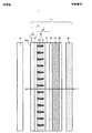
図2には、図1にII−IIで示した線に沿った水平方向における映像源ユニット1の厚さ方向水平断面、図3は図1にIII−IIIで示した線に沿った鉛直方向における映像源ユニット1の厚さ方向断面を表した。図2、図3はそれぞれ映像源ユニット1の層構成を模式的に示している。
2 shows a horizontal cross section in the thickness direction of the
図1乃至図3からわかるように、映像源ユニット1は複数の層が積層されており、面光源装置10及び液晶ユニット15が厚さ方向に並べられている。以下詳しく説明する。
As can be seen from FIGS. 1 to 3, the
面光源装置10は、通常の液晶表示装置に用いられるものを適用することができる。
As the surface
液晶ユニット15は、面光源装置10からの光を透過させ光源光に映像情報を付与するとともに、観察者にとって見易い映像となるように各種機能を有する部材である。本形態では液晶ユニット15は、面光源装置10に近い側から、光制御フィルタ16、第一偏光板40、液晶表示パネル41、第二偏光板42、及び機能層45を備えており、これらが積層されている。ここで光制御フィルタ16は、面光源装置10に近い側からプリズムシート20、光制御シート30を有して構成されている。
The
プリズムシート20は、光制御フィルタ16を構成する1つの部材であり、シート状に形成された本体部21と、本体部21の面のうち、面光源装置10側の面、つまり入光側面に設けられた単位プリズム部22と、を有している。図4には、図2のうちプリズムシート20の一部に注目して拡大した図を示した。ここでndはプリズムシート20に含まれる本体部21のシート面の法線方向を表わしている。
The
プリズムシート20は、後述するように、面光源装置10から平行に出射された光源光を所望の方向に偏向する機能(指向性偏向機能)を有する層である。この指向性偏向機能は、プリズムシート20のうち、主として単位プリズム部22によって発揮される。
As will be described later, the
図2、及び図4に表れているように、本体部21は、単位プリズム部22を支持する機能を有する平板状のシート部材である。そして、本体部21の面のうち、面光源装置10に対向する側とは反対側の面が出光側面となる。本形態において、本体部21の出光側面は、平坦(平ら)で平滑な面として形成され、後述する光制御シート30が接着剤により積層されている。
As shown in FIGS. 2 and 4, the
単位プリズム部22は、本体部21の面光源装置10側となる面に設けられ、図2及び図4によく表れているように、複数の単位プリズム22aが本体部21の面に沿った1つの方向(本形態では鉛直方向)に延び、当該延びる方向とは異なる方向(本形態では水平方向)並べられている。すなわち、単位プリズム22aは、図2、図4に示したプリズム形状の断面(本形態では三角形断面形状)を維持して1つの方向に延び、延びる方向に直交する方向に並べられた柱状の部材である。単位プリズム22aの延在する方向は、単位プリズム22aが並べられる方向に直交する他、後述する光制御シート30の光透過部33、光吸収部34が延びる方向に対して正面視で交差し、この角度は90度ずれた方向であることが好ましい。従って、本形態では単位プリズム22aが延びる方向と光吸収部34bが延びる方向とは平面視で直交する。
なお、単位プリズム22aが延びる方向は映像光を偏向する方向に交差する方向となる(本形態では単位プリズム22aは鉛直方向に延び、偏向方向は水平方向左右である。)。
The
The direction in which the
本形態では1つの例として三角形断面である単位プリズム22aについて説明したが、これに限らず他のプリズム形状の断面であってもよい。プリズム形状は光を分散、屈折、全反射、及び複屈折の少なくとも1つを起こさせる界面を構成するために該界面の一方と他方とで屈折率が異なるように形成した多面体に基づく形状である。
In this embodiment, the
図2、図4からわかるように、本形態において単位プリズム22aは、本体部21の入光側を底辺とし、法線ndを高さ方向として面光源装置10側に位置する頂点を有する二等辺三角形の断面を具備する。従って、単位プリズム22aの2つの斜辺は、法線方向ndと平行な軸を対称軸として、線対称となっている。これにより、後述するように法線方向ndから単位プリズム22aに入射した光は、単位プリズム22aの並列方向に平行な面(本形態では水平面)左右に偏向され、偏向された方向に輝度のピークを有する光が進行する。
As can be seen from FIGS. 2 and 4, in this embodiment, the
ここで、単位プリズム22aの寸法は特に限定されるものではなく、所望の偏向方向に応じて決めることができる。例えば単位プリズム22aの屈折率を1.55、図4に表した単位プリズム22aの頂角θ1を90°とすることにより、輝度のピークを法線ndに対して水平方向左右28°の向きに偏向することができる。
Here, the dimension of the
以上のような構成を有するプリズムシート20は、押し出し成型により、又は、本体部21上に単位プリズム22aを賦型することにより、製造することができる。プリズムシート20をなす材料としては、種々の材料を使用することができる。ただし、表示装置に組み込まれる光学シート用の材料として広く使用され、優れた機械的特性、光学特性、安定性および加工性等を有するとともに安価に入手可能な材料、例えば、アクリル、スチレン、ポリカーボネート、ポリエチレンテレフタレート、アクリロニトリル等の一以上を主成分とする透明樹脂や、エポキシアクリレートやウレタンアクリレート系の反応性樹脂(電離放射線硬化型樹脂等)が好適に使用され得る。
The
図5には、1つの変形例のプリズムシート20’を説明する図を示した。図5は図4に相当する図である。本例のプリズムシート20’は、本体部21及び単位プリズム部22’を有している。本体部21はプリズムシート20に具備される本体部21と同様である。
FIG. 5 is a diagram illustrating a
上記したプリズムシート20では、単位プリズム22aが二等辺三角形の断面を有していたのに対し、プリズムシート20’の単位プリズム部22’を構成する単位プリズム22a’は斜辺を形成する2つの辺で法線ndと成す角が異なる。すなわち図5に表したように、一方の斜辺22b’が法線に対してθ22を有して傾斜しており、他方の斜辺22c’が法線に対してθ23を有して傾斜している。
これにより、後述するように法線方向ndから単位プリズム22a’に入射した光は、単位プリズム22a’の並列方向に平行な面(本形態では水平面)左右において偏向される程度が異なる。このように斜辺の角度を変えることにより、光源光の輝度のピークの向きを制御することができる。例えば単位プリズム22a’の屈折率を1.55とし、図5にθ21で表した頂角を90°、斜辺22b’が法線ndと成す角であるθ22を30°、斜辺22c’が法線ndと成す角であるθ23を60°とすることにより、輝度のピークを法線ndに対して水平方向左右でそれぞれ異なる程度で偏向することが可能である。具体的には斜辺22b’により42°、斜辺22c’により17°でそれぞれ輝度のピークの方向を偏向できる。
In the
Thus, as described later, the light incident on the
図6には、他の変形例のプリズムシート20”を説明する図を示した。図6は図4に相当する図である。本例のプリズムシート20”は、本体部21及び単位プリズム部22”を有している。本体部21はプリズムシート20に具備される本体部21と同様である。
FIG. 6 is a view for explaining a
上記したプリズムシート20では、断面が二等辺三角形である単位プリズム22aが連続して配列されていたのに対し、プリズムシート20”の単位プリズム部22”に具備される単位プリズム22a”は隣り合う単位プリズム22a”との間にW32の間隙を有して配列されている。従って当該間隙部分においては本体部21の面21a”が露出し、本体部21の出光面と平行となっている。
これにより、プリズムシート20のように光源光を偏向することができるとともに、後述するように正面(法線nd方向)へも光源光を提供することができる。必要に応じてW32の大きさを変更すれば、正面へ提供される映像光の明るさを調整することが可能である。例えば単位プリズム22a”の屈折率を1.55、図6にθ3で表した単位プリズム22a”の頂角を90°、図6にW31で表したピッチを120μm、図6にW32で表した間隔部分を40μmとすることにより、輝度のピークの向きを、法線ndに対して0度(正面)、水平方向左右に28°のそれぞれとなるように偏向することができる。
In the
Thereby, the light source light can be deflected like the
本形態では本体部21の出光面と平行である面21a”を単位プリズム22a”の間隙により形成したが、この他、単位プリズムのうち突出する頂部を出光面と平行になるように切断したような形態によっても面21a”と同様の効果を奏するものとなる。このときには単位プリズムの断面は台形となる。
In this embodiment, the
図1乃至図3に戻り光制御シート30について説明する。光制御シート30は光制御フィルタ16を構成する1つの部材であり、本形態ではプリズムシート20のうち面光源装置10とは反対側に積層されている。光制御シート30は、光を透過するとともに不要な光の少なくとも一部を吸収する機能を有している。図7には図3のうち光制御シート30の一部に注目して拡大した図を示した。図3、図7からわかるように、光制御シート30は、基材層31及び光制御層32を有している。
Returning to FIGS. 1 to 3, the
基材層31は、光制御層32を形成するための基材となる層である。従って、基材層31は光透過性を有し、光制御層32を形成及び保持することができる程度に強度を有していればよい。従って、基材層31を構成する材料は特に限定されることはないが、プリズムシート20の本体部21と同様のものを挙げることができる。
The
光制御層32は上記基材層31のうち面光源装置10側となる面に積層されており、基材層31の当該一方の面に沿って光を透過可能に並列された複数の光透過部33と、隣接する2つの光透過部33の間に並列された複数の光吸収部34と、を備えている。そして、本形態では光透過部33及び光吸収部34は、図3、図7に示した断面を有して図2に表れるように液晶ユニット15のシート面に沿った1方向(本形態では水平方向)に延び、当該延びる方向とは異なる方向(本形態では鉛直方向)に複数の光透過部33及び光吸収部34が交互に並列されている。
当該光透過部33、及び光吸収部34が延びる方向は上記プリズムシート20により光源光が偏向される方向に交差しない方向であることが好ましい。すなわち、光吸収部34が延びる方向は上記した通り単位プリズム22aが延びる方向と平面視で直交することが好ましい。
The
The direction in which the
光透過部33は、映像光を透過する機能を有する部位で、図3、図7に表れる断面において、略台形の断面を有する要素である。当該略台形断面における上底が面光源装置10側、該上底より長い下底が観察者側にそれぞれ配置されている。本形態では隣り合う光透過部33の下底側(観察者側)が連結されている。
The
光透過部33は、光透過性を有する材料により形成されている。このような材料は特に限定されることはないが、例えば、アクリル、スチレン、ポリカーボネート、ポリエチレンテレフタレート、アクリロニトリル等の1つ以上を主成分とする透明樹脂や、エポキシアクリレートやウレタンアクリレート系の反応性樹脂(電離放射線硬化型樹脂等)を用いることができる。ここで光透過部33の屈折率は特に限定されることはないが、適用する材料の入手性の観点等から1.49〜1.56であることが好ましい。
The
光吸収部34は、隣り合う光透過部33間に形成される光を吸収する機能を有する部位であり、本形態では略台形を有する。従って光吸収部34には光を吸収する材料が含有されており、この略台形断面における上底が観察者側、該上底より長い下底がその反対側である面光源装置10側に向けられている。
ここで、光吸収部34の略台形断面における斜辺(脚部)は、液晶ユニット15の厚さ方向(図2、図3、図7の紙面左右方向)に対して0度以上10度以下の角度をなしていることが好ましい。本形態では、光吸収部34は断面が略台形である例を示したが、これに限らず正方形、長方形、平行四辺形であってもよい。また、上記斜辺の傾きは必ずしも一定である必要はなく、液晶ユニット15の厚さ方向位置によって変化した折れ線状であってもよいし、曲線状であってもよい。さらに、光吸収部34の上底の長さを小さくして断面を略三角形とすることもできる。
The
Here, the hypotenuse (leg part) in the substantially trapezoidal cross section of the
このような光吸収部34は例えば透明樹脂中に光吸収性を有する材料を含有することにより形成することができる。
透明樹脂としては例えば電離放射線硬化型樹脂等を用いることができ、特に限定されることはないが、例えば電子線、紫外線等の電離放射線により硬化する特徴を有するウレタンアクリレート系、エポキシアクリレート系等のアクリレート系樹脂を用いることができる。
一方、光吸収性を有する材料としては、可視光である迷光や外光等の不要光を吸収する機能を有すればよく、例えばカーボンブラック、グラファイト、黒色酸化鉄等の金属塩等、顔料、染料を挙げることができる。
図3、図7には透明樹脂に光吸収性を有する黒色粒子が分散されている態様を示した。ここで黒色粒子は、上記カーボンブラック、グラファイト、黒色酸化鉄等の金属塩等、顔料、染料等により光吸収性を有するように形成された粒子状の物質である。
Such a
As the transparent resin, for example, an ionizing radiation curable resin can be used, and is not particularly limited. However, for example, urethane acrylate type, epoxy acrylate type, etc. having characteristics of being cured by ionizing radiation such as electron beam and ultraviolet ray. An acrylate resin can be used.
On the other hand, the light-absorbing material only needs to have a function of absorbing unnecessary light such as stray light and external light that is visible light, such as carbon black, graphite, metal salts such as black iron oxide, pigments, Mention may be made of dyes.
3 and 7 show a mode in which black particles having light absorption properties are dispersed in a transparent resin. Here, the black particles are particulate substances formed so as to have a light absorption property using a metal salt such as carbon black, graphite, or black iron oxide, a pigment, a dye, or the like.
光制御シート30は例えば次のように製造される。図8に説明のための図を示した。
始めに、基材層31となる基材31’の上に、光透過部33を形成する。光透過部33を形成するには、光透過部33の形に対応した表面形状を有する金型ロール52を準備する。次に、当該金型ロール52とニップロール51との間に基材31’を送り込む。図8に示した矢印VIIIは、基材31’を送り込む方向である。基材31’の送り込みに合わせて、金型ロール52と基材31’との間に供給装置55から光透過部33を構成する組成物50の液滴を供給し続ける。供給装置55から基材31’上に組成物50を供給するとき、金型ロール52と基材31’との間に、組成物50が溜まったバンクが形成されるようにする。このバンクにおいて、組成物50が基材31’の幅方向に広がる。
For example, the
First, the
上記のようにして金型ロール52と基材31’との間に供給された組成物50は、金型ロール52およびニップロール51間の押圧力により、基材31’と金型ロール52との間に充填される。その後、光照射装置54によって組成物50に紫外線等を照射し、組成物50を硬化させることによって光透過部33を形成することができる。光透過部33が形成された後、基材31’上に光透過部33が形成されたシートは、剥離ロール53を介して引かれることによって、金型ロール52から引き剥がされる。そして所定の大きさに切断される。
これにより基材層31及び該基材層31上に光透過部33が積層された中間部材を得る。
The
Thereby, the intermediate member in which the
得られた中間部材に対して硬化する前の光吸収部34を構成する組成物を過剰に供給し、ブレードで押圧して掻き取るように移動させる。これにより余分な組成物を除外するとともに、隣り合う光透過部33間に組成物が充填される。その後、当該組成物を適切な方法で硬化させる。これにより、光透過部33間に光吸収部34が形成される。
以上により基材層31上に光制御層32が積層された光制御シート30を得る。
The composition constituting the
Thus, the
図1乃至図3に戻り、他の構成について説明を続ける。第一偏光板40、及び第二偏光板42は液晶表示パネル41を挟んで面光源装置10側及び観察者側のそれぞれに配置される板状の部材である。第一偏光板40及び第二偏光板42は、入射した光を直交する二つの偏光成分(P波およびS波)に分解し、一方の方向(透過軸と平行な方向)の偏光成分(例えば、P波)を透過させ、当該一方の方向に直交する他方の方向(吸収軸と平行な方向)の偏光成分(例えば、S波)を吸収する機能を有している。
Returning to FIG. 1 to FIG. 3, description of other configurations will be continued. The first
一方、液晶表示パネル41には、一つの画素を形成する領域毎に、電界印加がなされ得るようになっている。そして、電界印加された液晶表示パネル41の配向は変化するようになる。面光源装置10側(すなわち入光側)に配置された第一偏光板40を透過した特定方向の偏光成分(例えばP波)は、電界印加された液晶表示パネル41の部位を通過する際にその偏光方向を90°回転させ、その一方で、電界印加されていない液晶表示パネル41の部位を通過する際にその偏光方向を維持する。このため、液晶表示パネル41への電界印加の有無によって、第一偏光板40を透過した特定方向の偏光成分(例えばP波)が、第一偏光板40の出光側に配置された第二偏光板42をさらに透過するか、又は、第二偏光板42で吸収されて遮断されるか、を制御することができる。
On the other hand, an electric field can be applied to the liquid
このようにして第一偏光板40、第二偏光板42及び液晶表示パネル41により、面光源装置10からの光の透過または遮断を画素毎に制御し、映像を表現することができるように構成されている。
In this way, the first
機能層45は、一層または複数の層からなる積層体によって構成することができる。機能層45に備えられる層としては、例えば、ハードコート層が挙げられる。ハードコート層は、表示機器の最も観察者側に配置されており、表示機器の表示面を構成する。したがって、ハードコート層は、外部との接触に起因した擦傷に対する耐性が付与されている。このようなハードコート層は、例えば、光硬化型樹脂を硬化させることによって形成できる。当該光硬化型樹脂の具体例としては、アクリルウレタン系の光硬化型樹脂を挙げることができる。また、ハードコート層は、表示機器の表示面を構成するため、場合によっては防眩機能を有していることが好ましい。防眩機能を有するハードコート層によれば、表示機器の表示面での外光の反射や外部像の写りこみを防止して、表示機器の表示面に表示される映像の視認性を向上させることができる。
また、機能層45に備えられる層はハードコート層に限定されず、公知の表示機器に備えられるものを適宜適用することができる。
The
The layer provided in the
以上示した各構成において、プリズムシート20のうち、単位プリズム部22とは反対側の本体部21に光制御シート30の光制御層32が接着剤により固定される。そして光制御シート30の基材層31側に第一偏光板40、液晶表示パネル41、及び第二偏光板42がこの順でそれぞれ積層される。そして第二偏光板42の観察者側となる側に所定の間隔を有して機能層45が配置されて、液晶ユニット15となる。
一方、面光源装置10の光源光出射側に、作製した液晶ユニット15を所定の間隔を有して配置し、両者の外縁を互いに固定する等して位置決めをおこない、映像源ユニット1を得ることができる。
In each configuration described above, the
On the other hand, the manufactured
以上説明した映像源ユニット1を備える液晶表示装置によれば、例えば次のように観察者に映像光を提供することができる。光路例を示しつつ説明する。ただし、ここで示す光路例は概念的なものであり、反射角や屈折角等を厳密に表したものではない。
According to the liquid crystal display device including the
図2に示したように、面光源装置10で平行化されて出射した光L21はプリズムシート20の単位プリズム22aの斜面に達する。図2に光L21、図3に光L31、図4に光L41、L42で表したように、単位プリズム22aが延びる方向に直交する方向(本形態では水平方向)に関しては映像光が到達した斜面により、当該水平方向左右のいずれかに偏向される(図2のL21、図4のL41、L42)。偏向の程度は単位プリズム22aの法線ndに対する斜辺の角度や単位プリズム22aの屈折率等により決まる。
一方、図3に表した光L31のように、単位プリズム22aが延びる方向に平行な方向(本形態では鉛直方向)に関してはほとんど偏向されることなく正面の方向を維持する。
以上からわかるように、プリズムシート12により、光は光吸収部34が並べられる方向とは異なる方向について所望の方向(本形態では水平方向左右)に偏向され、当該左右方向において輝度のピークを有する光となる。
As shown in FIG. 2, the light L <b> 21 collimated and emitted by the surface
On the other hand, as in the light L31 shown in FIG. 3, the front direction is maintained with little deflection with respect to the direction parallel to the direction in which the
As can be seen from the above, the prism sheet 12 causes light to be deflected in a desired direction (horizontal left and right in this embodiment) in a direction different from the direction in which the
プリズムシート20により上記のように偏向された光は、図2に光L21、図3にL31、及び図7にL71で示したように光制御層32の光透過部33を透過してそのままの向きで液晶表示パネル42で映像情報を得てから観察者に出射される。従って、本形態では水平方向左右において明るい映像光を観察することができる。
一方、図7に光L72、L73で示したように、何らかの理由で鉛直方向に大きな角度を有して光制御層32に入射した光は光吸収部34に入射してここで吸収される。従って、鉛直方向については上下方向へ進む光が遮断されて視野角が制限される。
The light deflected as described above by the
On the other hand, as indicated by the lights L72 and L73 in FIG. 7, the light incident on the
このような光制御フィルタ16、並びにこれを備える液晶ユニット15、映像源ユニット1、及び液晶表示装置によれば、左右方向に存在する観察者にとって見易い映像光を提供することができる。すなわち、光透過部33、光吸収部34により視野角を意図的に制限した方向とは異なる方向について光を適切に制御することができる。例えば自動車のコンソール中央に配置された液晶表示装置は、運転席及び助手席に着席した者が見ることが多いので液晶表示装置の正面が明るく、その左右方向の映像光が暗いことは不便である。これに対して光制御フィルタ16、並びにこれを備える液晶ユニット15、映像源ユニット1、及び液晶表示装置によれば、このような不具合を解消することが可能である。
一方、本形態では、光制御層32により鉛直方向への光の拡散を小さく抑えている。これにより例えば自動車のコンソールに液晶表示装置を配置した場面を考えたとき、特に鉛直方向上方への映像光がフロントガラスに映り込むことを防止することが可能となり、より利便性が高まる。
According to the
On the other hand, in the present embodiment, the
図5に示したプリズムシート20’を備えた例では、図5に示した光L51、L52のように、左右方向を均等でなく、左右方向一方に角度が大きく偏向した位置で輝度のピークを得ることができる。このように、所望の方向へ高い輝度の光を提供することが可能となる。
In the example provided with the
また、図6に示したプリズムシート20”を備えた例では図6に示した光L61、L62、L63のように、図4に示した光L41、L42と同様な偏向(光L61、L62)に加え、設けられた本体部21の面21a”を透過した光L63は偏向されることなくプリズムシート20”を透過する。このように、正面方向へも輝度のピークが必要な場合には、面21a”を形成することにより可能となる。上記したように面21a”の幅W32の大きさによって正面輝度の程度を調整することができる。
Further, in the example provided with the
図9は第二の形態を説明する図であり、映像源ユニット51の水平方向断面で層構成を模式的に表している。図9は図2に相当する図である。
映像源ユニット51では、光制御フィルタ66において、プリズムシート70が上記プリズムシート20とは異なり本体部21を有しておらず、単位プリズム部22のみで形成されている。そして当該単位プリズム部22が光制御シート39の光制御層32に積層されている。これにより、上記した液晶ユニット、映像源ユニット、及び液晶表示装置と同様の機能を有する他、映像源ユニットを薄く形成することができる。
FIG. 9 is a diagram for explaining the second embodiment, and schematically shows the layer structure in a horizontal section of the
In the
このような光制御フィルタ66は、光制御シート30を形成した後に、光制御層32に対して直接単位プリズム部22を形成することにより作製できる。
Such a
図10は第三の形態を説明する図であり、映像源ユニット101の層構成を模式的に表した図である。図10は図2に相当する。
映像源ユニット101は第一偏光板40と液晶表示パネル41との間に光制御フィルタ16を配置した例である。このような映像源ユニット101も、上記した映像源ユニット1と同様の効果を奏するものとなる。
FIG. 10 is a diagram for explaining the third embodiment, and is a diagram schematically showing the layer configuration of the
The
図11は第四の形態を説明する図であり、映像源ユニット151の層構成を模式的に表した図である。図11は図2に相当する。
映像源ユニット151は光制御フィルタ16を最も観察者側に配置した例である。このような映像源ユニット151も、上記した映像源ユニット1と同様の効果を奏するものとなる。
FIG. 11 is a diagram for explaining the fourth embodiment, and is a diagram schematically showing the layer configuration of the
The
さらに、図11に破線及び直線矢印で概念的に示したように、本形態では既存の液晶ユニットに対して追加するように観察者側から光制御フィルタ16を後付け、場合によっては取り外しもすることができ、利便性を高めることができる。このときには液晶表示装置を構成するに際し、液晶ユニット165のうち光制御フィルタ16以外は筐体内に収められることにより保持され、光制御フィルタ16は必ずしも筐体に保持されることなく液晶ユニット165の他の部材により保持されていればよい。
Furthermore, as conceptually shown by broken lines and straight arrows in FIG. 11, in this embodiment, the
1、101 映像源ユニット
10、面光源装置
15 液晶ユニット
16 光制御フィルタ
20 プリズムシート
21 本体部
22 単位プリズム部
22a 単位プリズム
30 光制御シート
31 基材層
32 光制御層
33 光透過部
34 光吸収部
40 第一偏光板
41 液晶表示パネル
42 第二偏向層
45 機能層
DESCRIPTION OF SYMBOLS 1,101
Claims (9)
前記複数の層のうちの1つであり、平板状のシート部材である本体部の一方の面に沿ってプリズム形状の断面を有して一方に延びるとともに、該延びる方向とは異なる方向に配列される複数の単位プリズムを具備するプリズムシートと、
前記複数の層の1つである光制御層と、を備え、
前記プリズムシートは、
前記単位プリズムが、配列される方向の断面において本体部の法線に対して傾きを有する少なくとも2つの辺を有し、当該辺の傾きは前記法線方向に対して非対称とされており、
前記光制御層は、
前記一方とは異なる方向に延びるとともに、該延びる方向とは異なる方向に配列される、光を透過する複数の光透過部と、
台形断面を有し、隣り合う前記光透過部間に光を吸収する材料が含まれることにより光を吸収する複数の光吸収部と、を有し、
前記単位プリズムが延びる方向と、前記光透過部が延びる方向とが、前記光制御フィルタを平面視したときに交差する、光制御フィルタ。 A light control filter in which a plurality of layers are laminated, and controls and emits incident light,
It is one of the plurality of layers and has a prism-shaped cross section along one surface of the main body portion that is a flat sheet member , and extends in one direction, and is arranged in a direction different from the extending direction. A prism sheet comprising a plurality of unit prisms,
A light control layer that is one of the plurality of layers,
The prism sheet is
The unit prism has at least two sides having an inclination with respect to the normal line of the main body in a section in the arrangement direction, and the inclination of the side is asymmetric with respect to the normal direction,
The light control layer includes
A plurality of light transmitting parts that transmit light and that extend in a direction different from the one and are arranged in a direction different from the extending direction;
Having a trapezoidal cross section, and having a plurality of light absorbing portions that absorb light by including a material that absorbs light between the adjacent light transmitting portions,
A light control filter in which a direction in which the unit prism extends and a direction in which the light transmission portion extends intersect when the light control filter is viewed in plan.
前記複数の層のうちの1つであり、平板状のシート部材である本体部の一方の面に沿ってプリズム形状の断面を有して一方に延びるとともに、該延びる方向とは異なる方向に配列される複数の単位プリズムを具備するプリズムシートと、 It is one of the plurality of layers and has a prism-shaped cross section along one surface of the main body portion that is a flat sheet member, and extends in one direction, and is arranged in a direction different from the extending direction. A prism sheet comprising a plurality of unit prisms,
前記複数の層の1つである光制御層と、を備え、 A light control layer that is one of the plurality of layers,
前記プリズムシートは、 The prism sheet is
前記単位プリズム又は前記単位プリズムの間に、前記本体部の出光面に平行な面を具備し、Between the unit prisms or the unit prisms, comprising a surface parallel to the light exit surface of the main body,
前記光制御層は、 The light control layer includes
前記一方とは異なる方向に延びるとともに、該延びる方向とは異なる方向に配列される、光を透過する複数の光透過部と、 A plurality of light transmitting parts that transmit light and that extend in a direction different from the one and are arranged in a direction different from the extending direction;
台形断面を有し、隣り合う前記光透過部間に光を吸収する材料が含まれることにより光を吸収する複数の光吸収部と、を有し、Having a trapezoidal cross section, and having a plurality of light absorbing portions that absorb light by including a material that absorbs light between the adjacent light transmitting portions,
前記単位プリズムが延びる方向と、前記光透過部が延びる方向とが、前記光制御フィルタを平面視したときに交差する、光制御フィルタ。 A light control filter in which a direction in which the unit prism extends and a direction in which the light transmission portion extends intersect when the light control filter is viewed in plan.
請求項1乃至3のいずれかに記載の光制御フィルタと、偏光板と、液晶表示パネルと、を備え、
前記光制御フィルタが前記偏光板に積層されている、液晶ユニット。 A liquid crystal unit capable of displaying images by laminating a plurality of layers,
A light control filter according to any one of claims 1 to 3 , a polarizing plate, and a liquid crystal display panel,
A liquid crystal unit in which the light control filter is laminated on the polarizing plate.
前記面光源装置の光源光出射側に配置され、複数の層が積層された液晶ユニットとを備え、
前記液晶ユニットは、
請求項1乃至3のいずれかに記載の光制御フィルタと、偏光板と、液晶表示パネルと、を備え、
前記液晶ユニットの前記光制御フィルタの前記プリズムシートが前記光制御層よりも前記面光源装置側に配置され、前記光制御層よりも観察者側に前記液晶表示パネルが設けられている、映像源ユニット。 A surface light source device;
A liquid crystal unit disposed on the light source light emitting side of the surface light source device and having a plurality of layers laminated,
The liquid crystal unit is
A light control filter according to any one of claims 1 to 3 , a polarizing plate, and a liquid crystal display panel,
An image source in which the prism sheet of the light control filter of the liquid crystal unit is disposed closer to the surface light source device than the light control layer, and the liquid crystal display panel is provided closer to the viewer than the light control layer unit.
前記面光源装置の光源光出射側に配置され、複数の層が積層された液晶ユニットと、を備え、
前記液晶ユニットは、
請求項1乃至3のいずれかに記載の光制御フィルタと、偏光板と、液晶表示パネルと、を備え、
前記光制御フィルタが最も観察者側となる位置に配置される、映像源ユニット。 A surface light source device;
A liquid crystal unit disposed on the light source light emitting side of the surface light source device and laminated with a plurality of layers,
The liquid crystal unit is
A light control filter according to any one of claims 1 to 3 , a polarizing plate, and a liquid crystal display panel,
An image source unit in which the light control filter is disposed at a position closest to the viewer.
Priority Applications (1)
| Application Number | Priority Date | Filing Date | Title |
|---|---|---|---|
| JP2013062416A JP6171456B2 (en) | 2013-03-25 | 2013-03-25 | Light control filter, liquid crystal unit, video source unit, liquid crystal display device |
Applications Claiming Priority (1)
| Application Number | Priority Date | Filing Date | Title |
|---|---|---|---|
| JP2013062416A JP6171456B2 (en) | 2013-03-25 | 2013-03-25 | Light control filter, liquid crystal unit, video source unit, liquid crystal display device |
Publications (2)
| Publication Number | Publication Date |
|---|---|
| JP2014186241A JP2014186241A (en) | 2014-10-02 |
| JP6171456B2 true JP6171456B2 (en) | 2017-08-02 |
Family
ID=51833858
Family Applications (1)
| Application Number | Title | Priority Date | Filing Date |
|---|---|---|---|
| JP2013062416A Active JP6171456B2 (en) | 2013-03-25 | 2013-03-25 | Light control filter, liquid crystal unit, video source unit, liquid crystal display device |
Country Status (1)
| Country | Link |
|---|---|
| JP (1) | JP6171456B2 (en) |
Families Citing this family (5)
| Publication number | Priority date | Publication date | Assignee | Title |
|---|---|---|---|---|
| JP6501157B2 (en) * | 2015-06-30 | 2019-04-17 | 大日本印刷株式会社 | Surface light source device and display device |
| JP6710957B2 (en) * | 2015-12-17 | 2020-06-17 | 大日本印刷株式会社 | Image source unit and display device |
| JP2017219619A (en) * | 2016-06-06 | 2017-12-14 | 大日本印刷株式会社 | Image source unit |
| JP7205463B2 (en) | 2017-03-31 | 2023-01-17 | 大日本印刷株式会社 | Optical sheet, light control member, surface light source device, image source unit, and display device |
| CN108897081A (en) * | 2018-07-23 | 2018-11-27 | 宁波激智科技股份有限公司 | A kind of optical thin film and preparation method thereof |
Family Cites Families (7)
| Publication number | Priority date | Publication date | Assignee | Title |
|---|---|---|---|---|
| JP2003058066A (en) * | 2001-08-03 | 2003-02-28 | Three M Innovative Properties Co | Optical filter |
| JP2006004772A (en) * | 2004-06-17 | 2006-01-05 | Sharp Corp | Lighting apparatus and liquid crystal display device |
| JP2007258152A (en) * | 2006-02-24 | 2007-10-04 | Citizen Electronics Co Ltd | Backlight unit and display device provided with the same |
| KR20070090654A (en) * | 2006-03-03 | 2007-09-06 | 쓰리엠 이노베이티브 프로퍼티즈 컴파니 | Reduction of Moiré Phenomena in LCD Devices Including Light Control Films |
| JP5110350B2 (en) * | 2006-09-29 | 2012-12-26 | Nltテクノロジー株式会社 | Optical element and illumination optical device, display device, and electronic apparatus using the same |
| KR101546554B1 (en) * | 2007-12-21 | 2015-08-25 | 쓰리엠 이노베이티브 프로퍼티즈 컴파니 | Light control film |
| CN102540306B (en) * | 2010-12-31 | 2015-03-25 | 北京京东方光电科技有限公司 | Grating, liquid crystal display device and manufacture methods of grating and liquid crystal display device |
-
2013
- 2013-03-25 JP JP2013062416A patent/JP6171456B2/en active Active
Also Published As
| Publication number | Publication date |
|---|---|
| JP2014186241A (en) | 2014-10-02 |
Similar Documents
| Publication | Publication Date | Title |
|---|---|---|
| CN101815965B (en) | Light diffusion sheet and liquid crystal display device | |
| JP2007279424A (en) | Privacy filter sheet and display device containing the same | |
| JP6171456B2 (en) | Light control filter, liquid crystal unit, video source unit, liquid crystal display device | |
| WO2018181966A1 (en) | Optical sheet, light control member, planar light source device, image source unit, and display device | |
| CN101809488A (en) | Light diffusion sheet and liquid crystal display device | |
| JP5277931B2 (en) | Optical sheet and image display device | |
| JP7395862B2 (en) | Reflective screen, video display device | |
| JP5970786B2 (en) | Optical sheet and video display device including the same | |
| JP6834153B2 (en) | Space floating image display device | |
| CN101999093A (en) | Liquid crystal display device | |
| JP6314377B2 (en) | Vehicle display system | |
| JP2014186249A (en) | Screen unit, multiscreen, back-face projection type display device | |
| JP4853418B2 (en) | Optical sheet and display device including the optical sheet | |
| JP5402323B2 (en) | Screen and projection system | |
| JP4888973B2 (en) | Backlight unit and display device | |
| JP6932977B2 (en) | Image source unit and liquid crystal display device | |
| JP6922220B2 (en) | Optical sheet, image source unit, and liquid crystal display device | |
| JP5439786B2 (en) | Light diffusion sheet, liquid crystal image source unit, and liquid crystal display device | |
| JP2014119607A (en) | Transmission type screen, rear-projection type display device and multi-screen display device | |
| JP7441397B2 (en) | Optical sheets and liquid crystal display devices | |
| JP2016151710A (en) | Optical sheet, video source unit, and video display device | |
| JP6766367B2 (en) | Display device and liquid crystal display device | |
| JP2014182168A (en) | Transmission type screen, rear projection display device | |
| JP2012098525A (en) | Reflection screen for stereoscopic image display, and stereoscopic image display system | |
| JP4998126B2 (en) | Optical sheet and display device |
Legal Events
| Date | Code | Title | Description |
|---|---|---|---|
| A621 | Written request for application examination |
Free format text: JAPANESE INTERMEDIATE CODE: A621 Effective date: 20160125 |
|
| A977 | Report on retrieval |
Free format text: JAPANESE INTERMEDIATE CODE: A971007 Effective date: 20161007 |
|
| A131 | Notification of reasons for refusal |
Free format text: JAPANESE INTERMEDIATE CODE: A131 Effective date: 20161025 |
|
| A521 | Written amendment |
Free format text: JAPANESE INTERMEDIATE CODE: A523 Effective date: 20161212 |
|
| TRDD | Decision of grant or rejection written | ||
| A01 | Written decision to grant a patent or to grant a registration (utility model) |
Free format text: JAPANESE INTERMEDIATE CODE: A01 Effective date: 20170606 |
|
| A61 | First payment of annual fees (during grant procedure) |
Free format text: JAPANESE INTERMEDIATE CODE: A61 Effective date: 20170619 |
|
| R150 | Certificate of patent or registration of utility model |
Ref document number: 6171456 Country of ref document: JP Free format text: JAPANESE INTERMEDIATE CODE: R150 |