JP6146615B2 - Rotating machine control device - Google Patents
Rotating machine control device Download PDFInfo
- Publication number
- JP6146615B2 JP6146615B2 JP2013204961A JP2013204961A JP6146615B2 JP 6146615 B2 JP6146615 B2 JP 6146615B2 JP 2013204961 A JP2013204961 A JP 2013204961A JP 2013204961 A JP2013204961 A JP 2013204961A JP 6146615 B2 JP6146615 B2 JP 6146615B2
- Authority
- JP
- Japan
- Prior art keywords
- rotating machine
- voltage
- output
- pulse signal
- inverter
- Prior art date
- Legal status (The legal status is an assumption and is not a legal conclusion. Google has not performed a legal analysis and makes no representation as to the accuracy of the status listed.)
- Active
Links
Images


Landscapes
- Control Of Ac Motors In General (AREA)
Description
本発明は、回転機制御装置に関し、さらに詳しくは、インバータを備える回転機制御装置に関する。 The present invention relates to a rotating machine control device, and more particularly to a rotating machine control device including an inverter.
従来から、インバータを用いてモータや発電機などの回転機の動作を制御することが行われている。インバータは、複数のスイッチング素子を備えている。各スイッチング素子が制御装置から供給されるスイッチング信号に応じてオンオフを切り替えることにより、交流電圧が直流電圧から生成される。回転機は、インバータから供給される交流電圧により駆動する。 Conventionally, the operation of a rotating machine such as a motor or a generator is controlled using an inverter. The inverter includes a plurality of switching elements. An AC voltage is generated from the DC voltage by switching each element on and off according to a switching signal supplied from the control device. The rotating machine is driven by an AC voltage supplied from an inverter.
インバータの制御方式として、パルス幅変調(PWM:Pulse Width Modulation)方式と、パルス振幅変調(PAM:Pulse Amplitude Modulation)方式とが知られている。 As an inverter control method, a pulse width modulation (PWM) method and a pulse amplitude modulation (PAM) method are known.
PWM方式では、パルス信号の振幅が固定される。パルス信号のパルス幅を変化させることにより、インバータ内のスイッチング素子のオンオフを切り替える。PWM方式によりインバータを駆動した場合、回転機の出力が低くなるにつれて、パルス信号のパルス幅が狭くなる。この結果、交流電圧に含まれる高周波成分が増加するため、回転機の損失が増加するという問題がある。 In the PWM method, the amplitude of the pulse signal is fixed. By changing the pulse width of the pulse signal, the switching element in the inverter is switched on and off. When the inverter is driven by the PWM method, the pulse width of the pulse signal becomes narrower as the output of the rotating machine becomes lower. As a result, since the high frequency component contained in the alternating voltage increases, there is a problem that the loss of the rotating machine increases.
PAM方式では、パルス信号のパルス幅が固定される。パルス信号の振幅を変化させることにより、インバータ内のスイッチング素子のオンオフを切り替える。しかし、回転機を低出力で駆動させる場合、パルス信号の振幅を低くしなければならない。この結果、回転機に供給される電圧が低くなるため、インバータの電流容量が大きくなり、インバータの応答性が低下するという問題がある。 In the PAM system, the pulse width of the pulse signal is fixed. By changing the amplitude of the pulse signal, the switching element in the inverter is switched on and off. However, when the rotating machine is driven at a low output, the amplitude of the pulse signal must be lowered. As a result, since the voltage supplied to the rotating machine is lowered, there is a problem that the current capacity of the inverter is increased and the response of the inverter is lowered.
特許文献1には、遠心機用モータの制御装置が開示されている。この制御装置は、モータに接続されるインバータの制御にPWM制御を用いる。また、特許文献2には、遠心機が開示されている。この遠心機は、PWM制御を用いてモータに印加される電圧を制御する。
しかし、これらの文献に開示された技術は、上述したPWM方式及びPAM方式の各々の問題点を解決するものではない。 However, the techniques disclosed in these documents do not solve the problems of the PWM method and the PAM method described above.
本発明の目的は、回転機が低出力で駆動するときの損失の増加を抑制するとともに、低出力で駆動するときの応答性を向上させることができる回転機制御装置を提供することである。 An object of the present invention is to provide a rotating machine control device capable of suppressing an increase in loss when the rotating machine is driven at a low output and improving responsiveness when driven at a low output.
本発明に係る回転機制御装置は、インバータと、前記インバータに第1の直流電圧と前記第1の直流電圧よりも低い第2の直流電圧のいずれか一方を供給し、前記第1の直流電圧が前記インバータに供給されるときに第1のパルス幅変調方式に基づくスイッチング信号を前記インバータに供給し、前記第2の直流電圧が前記インバータに供給されるときに第2のパルス幅変調方式に基づくスイッチング信号を前記インバータに供給する制御装置とを備える。前記第1のパルス幅変調方式では、第1のパルス信号が用いられる。前記第2のパルス幅変調方式では、前記第1のパルス信号の振幅よりも小さい振幅と前記第1のパルス信号のパルス幅よりも大きいパルス幅とを有する第2のパルス信号が用いられる。前記インバータから出力される交流電圧の1周期あたりの前記第1のパルス信号の面積の合計値は、前記1周期あたりの前記第2のパルス信号の面積の合計値と同じである。 The rotating machine control device according to the present invention supplies an inverter, and either the first DC voltage or the second DC voltage lower than the first DC voltage to the inverter, and the first DC voltage Is supplied to the inverter, a switching signal based on a first pulse width modulation method is supplied to the inverter, and a second pulse width modulation method is applied to the inverter when the second DC voltage is supplied to the inverter. And a control device for supplying a switching signal based on the inverter to the inverter. In the first pulse width modulation method, a first pulse signal is used. In the second pulse width modulation method, a second pulse signal having an amplitude smaller than the amplitude of the first pulse signal and a pulse width larger than the pulse width of the first pulse signal is used. The total value of the area of the first pulse signal per cycle of the AC voltage output from the inverter is the same as the total value of the area of the second pulse signal per cycle.
この構成によれば、制御装置は、第1の直流電圧をインバータに供給するときには、第1のパルス信号を用いてインバータの動作を制御するスイッチング信号を生成する。一方、制御装置は、第1の直流電圧よりも小さい第2の直流電圧をインバータに供給するときには、第2のパルス信号を用いてインバータの動作を制御するスイッチング信号を生成する。第2のパルス信号の振幅は、第1のパルス信号の振幅よりも小さく、第2のパルス信号のパルス幅は、第1のパルス信号のパルス幅よりも大きい。また、第1のパルス信号の面積の合計値は、第2のパルス信号の面積の合計値と同じである。なお、第1のパルス信号の合計値と、第2のパルス信号の面積の合計値とは、完全に一致していなくてもよく、ほぼ同一であればよい。これにより、PWM方式を用いて、高周波成分の少ない交流電圧を生成することができる。従って、回転機が低出力で駆動するときの損失の増加を抑制することができる。 According to this configuration, when the first DC voltage is supplied to the inverter, the control device generates a switching signal that controls the operation of the inverter using the first pulse signal. On the other hand, when supplying a second DC voltage smaller than the first DC voltage to the inverter, the control device generates a switching signal for controlling the operation of the inverter using the second pulse signal. The amplitude of the second pulse signal is smaller than the amplitude of the first pulse signal, and the pulse width of the second pulse signal is larger than the pulse width of the first pulse signal. The total area value of the first pulse signal is the same as the total area area of the second pulse signal. Note that the total value of the first pulse signal and the total value of the area of the second pulse signal do not have to be completely coincident with each other as long as they are substantially the same. Thereby, the alternating voltage with few high frequency components can be produced | generated using a PWM system. Therefore, an increase in loss when the rotating machine is driven at a low output can be suppressed.
また、インバータに第2の直流電圧を供給した場合、インバータから出力される交流の最大振幅が、インバータに第2の直流電圧を供給する場合よりも小さくなり、回転機が低駆動で出力する。このとき、第2のパルス信号のパルス幅を第1のパルス信号のパルス幅よりも大きくすることで、従来のPAM方式を用いる場合よりも、インバータから出力される交流電圧を大きくすることができる。従って、回転機が低出力で駆動するときの応答性を向上させることができる。 In addition, when the second DC voltage is supplied to the inverter, the maximum amplitude of the AC output from the inverter is smaller than that when the second DC voltage is supplied to the inverter, and the rotating machine outputs at a low drive. At this time, by making the pulse width of the second pulse signal larger than the pulse width of the first pulse signal, the AC voltage output from the inverter can be made larger than when the conventional PAM method is used. . Therefore, the response when the rotating machine is driven at a low output can be improved.
上記回転機制御装置において、前記制御装置は、回転機の第1の出力に対応する第1の指示信号と、前記第1の出力よりも小さい第2の出力に対応する第2の指示信号とのいずれかを出力し、前記回転機が第1の出力で駆動する場合、前記第1のパルス信号に基づくスイッチング信号を前記インバータに供給し、前記回転機が第2の出力で駆動する場合、前記第2のパルス信号に基づくスイッチング信号を前記インバータに供給する制御部と、前記第1の指示信号を前記制御部から受けた場合、入力直流電圧を前記第1の直流電圧に調整し、前記第2の指示信号を前記制御部から受けた場合、前記入力直流電圧を前記第2の直流電圧に調整する電圧調整部とを備える。 In the rotating machine control device, the control device includes a first instruction signal corresponding to a first output of the rotating machine, and a second instruction signal corresponding to a second output smaller than the first output. When the rotating machine is driven with a first output, the switching signal based on the first pulse signal is supplied to the inverter, and the rotating machine is driven with a second output. A control unit that supplies a switching signal based on the second pulse signal to the inverter; and when the first instruction signal is received from the control unit, an input DC voltage is adjusted to the first DC voltage, And a voltage adjustment unit that adjusts the input DC voltage to the second DC voltage when the second instruction signal is received from the control unit.
この構成によれば、回転機を第1の出力で駆動させる場合、制御装置は、インバータに第1の直流電圧を供給し、第1のパルス信号から第1のスイッチング信号を生成する。回転機を回転機を第1の出力よりも小さい第2の出力で駆動させる場合、制御装置は、インバータに第1の直流電圧よりも低い第2の直流電圧を供給し、第1のパルス信号のパルス幅よりも大きいパルス幅を有する第2のパルス信号を用いてスイッチング信号を生成する。これにより、交流電圧に含まれる高周波成分が抑制されるため、回転機が低出力で動作する際に生じる渦電流損の増加を抑制できる。 According to this configuration, when the rotating machine is driven with the first output, the control device supplies the first DC voltage to the inverter and generates the first switching signal from the first pulse signal. When the rotating machine is driven with a second output smaller than the first output, the control device supplies a second DC voltage lower than the first DC voltage to the inverter, and the first pulse signal A switching signal is generated using a second pulse signal having a pulse width larger than the pulse width of the second pulse signal. Thereby, since the high frequency component contained in an alternating voltage is suppressed, the increase in the eddy current loss which arises when a rotary machine operate | moves with a low output can be suppressed.
上記回転機制御装置において、前記制御部は、前記回転機のトルクと回転速度との関係を示す関係図を保持し、前記関係図と、前記回転機の駆動条件を指示する出力指令に含まれるトルク値と、前記出力指令に含まれる回転速度とを参照して前記第1又は第2の指示信号を出力し、前記出力指令に含まれるトルク値及び回転速度に基づいて、前記第1又は第2のパルス信号を生成する。 In the rotating machine control device, the control unit holds a relationship diagram indicating a relationship between the torque and the rotation speed of the rotating machine, and is included in the relationship diagram and an output command instructing a driving condition of the rotating machine. The first or second instruction signal is output with reference to the torque value and the rotation speed included in the output command, and the first or second instruction signal is output based on the torque value and the rotation speed included in the output command. 2 pulse signals are generated.
この構成によれば、回転機の駆動条件に応じて、スイッチング信号の生成に用いるパルス信号を変更することができる。従って、回転機の駆動条件が変化しても、損失の増加を抑えることができる。 According to this configuration, the pulse signal used for generating the switching signal can be changed according to the driving condition of the rotating machine. Therefore, even if the driving conditions of the rotating machine change, an increase in loss can be suppressed.
本発明のエンジンユニットは、本発明の回転機制御装置と、本発明の回転機制御装置により制御される回転機と、回転機の回転軸に連結された回転軸を含むエンジンとを備える。 The engine unit of the present invention includes a rotating machine control device of the present invention, a rotating machine controlled by the rotating machine control device of the present invention, and an engine including a rotating shaft connected to the rotating shaft of the rotating machine.
上記の構成によれば、エンジンとともに回転機を動力源として使用する際に、回転機を低出力で駆動させるときの損失の増加を抑制することができる。 According to said structure, when using a rotary machine as a power source with an engine, the increase in the loss when driving a rotary machine with low output can be suppressed.
以下、図面を参照し、本発明の実施の形態を詳しく説明する。図中同一又は相当部分には同一符号を付してその説明は繰り返さない。 Hereinafter, embodiments of the present invention will be described in detail with reference to the drawings. In the drawings, the same or corresponding parts are denoted by the same reference numerals and description thereof will not be repeated.
{1.回転機制御装置3の構成}
図1は、本実施の形態に係る回転機制御装置3を備える駆動装置100の機能ブロック図である。図1に示すように、駆動装置100は、交流電源1から供給される交流電圧Vsを直流電圧に変換し、変換された直流電圧から、モータ・ジェネレータ200(以下、「回転機200」と呼ぶ。)を駆動させるための交流電圧Vd1又はVd2を生成する。交流電圧Vd1,Vd2の詳細については、後述する。
{1. Configuration of rotating machine control device 3}
FIG. 1 is a functional block diagram of a
交流電圧Vs,Vd1,Vd2は、それぞれ、U相、V相及びW相を有する三相交流である。なお、図1において、交流電圧の各相の表示を省略する。以下、交流電圧Vs,Vd1,Vd2に関する説明において、各相については特に言及しない。 The alternating voltages Vs, Vd1, and Vd2 are three-phase alternating currents having a U phase, a V phase, and a W phase, respectively. In FIG. 1, the display of each phase of the AC voltage is omitted. Hereinafter, in the description of the AC voltages Vs, Vd1, and Vd2, no particular mention is made of each phase.
以下、回転機200をモータとして使用するときの回転機制御装置3の動作を説明し、回転機200を発電機として使用するときの回転機制御装置3の動作の説明を省略する。
Hereinafter, the operation of the rotating machine control device 3 when using the
駆動装置100は、コンバータ2と、回転機制御装置3とを備える。
The
コンバータ2は、交流電源1から供給される交流電圧Vsを整流して直流電圧Vcを生成する。なお、駆動装置100は、コンバータ2を備えない構成であってもよい。この場合、駆動装置100は、交流電源1に代えて、図示しない直流電源から直流電圧Vcの供給を受ければよい。
Converter 2 rectifies AC voltage Vs supplied from
回転機制御装置3は、コンバータ2から供給される直流電圧Vcから、出力指令49で指定された駆動条件で回転機200を回転させるための交流電圧Vd1又はVd2を生成する。回転機制御装置3は、制御装置30と、インバータ34とを備える。
The rotating machine control device 3 generates the AC voltage Vd1 or Vd2 for rotating the
{1.1.制御装置30の構成}
制御装置30は、コンバータ2から供給される直流電圧Vcから、直流電圧V1又はV2を生成する。直流電圧V1の電圧値は、直流電圧V2の電圧値よりも大きい。制御装置30は、直流電圧V1及びV2のいずれかをインバータ34に供給する。以下、直流電圧V1,V2の参照符号を、直流電圧V1,V2の電圧値として適宜使用する。
{1.1. Configuration of Control Device 30}
また、制御装置30は、直流電圧V1がインバータ34に供給されるときに第1のPWM方式に基づくスイッチング信号41をインバータ34に供給する。制御装置30は、直流電圧V2がインバータ34に供給されるときに第2のPWM方式に基づくスイッチング信号42をインバータ34に供給する。第1のPWM方式及び第2のPWM方式については、後述する。
In addition, the
インバータ34は、制御装置30から供給されるスイッチング信号41を用いて、直流電圧V1を交流電圧Vd1に変換する。つまり、交流電圧Vd1は、回転機200を高出力で駆動させる際に回転機200に供給される電圧である。インバータ34は、制御装置30から供給されるスイッチング信号42を用いて、直流電圧V2を交流電圧Vd2に変換する。つまり、交流電圧Vd2は、回転機200を低出力で駆動させる際に回転機200に供給される電圧である。
The
制御装置30は、制御部31と、電圧調整部32と、コンデンサ33とを備える。
The
制御部31は、出力指令49に基づいて、回転機200を高出力で駆動させるか低出力で駆動させるかを判断する。制御部31は、回転機200を高出力で駆動させる場合、高出力での駆動を示す指示信号43aを電圧調整部32に供給し、スイッチング信号41をインバータ34に供給する。制御部31は、回転機200を低出力で駆動させる場合、低出力での駆動を示す指示信号43bを電圧調整部32に供給し、スイッチング信号42をインバータ34に供給する。
Based on the
電圧調整部32は、指示信号43aを受けた場合、直流電圧Vcを直流電圧V1に調整する。一方、電圧調整部32は、指示信号43bを受けた場合、直流電圧Vcを直流電圧V2に調整する。電圧調整部32は、昇降圧回路などのスイッチング回路などのように、損失が小さい回路又は回路素子を用いることが望ましい。
When receiving the
コンデンサ33は、直流電圧V1又はV2を平滑化し、直流電圧V1又はV2に含まれるノイズを低減する。コンデンサ33の一方は、電圧調整部32の出力端子32aに接続され、他方は、出力端子32bに接続される。直流電圧V1又はV2は、出力端子32aから出力される。出力端子32bは、接地される。
The capacitor 33 smoothes the DC voltage V1 or V2 and reduces noise included in the DC voltage V1 or V2. One of the capacitors 33 is connected to the
{1.2.制御部31の構成}
図2は、図1に示す制御部31の機能ブロック図である。制御部31は、出力判断部35と、パルス信号生成部36と、スイッチング信号生成部37とを備える。
{1.2. Configuration of control unit 31}
FIG. 2 is a functional block diagram of the
出力判断部35は、出力指令49に含まれるトルク指令47及び回転速度指令48と、回転機200のトルクと回転速度との関係を示す関係図とに基づいて、回転機200を高出力で駆動させるか低出力で駆動させるかを判断する。出力判断部35は、高出力で駆動させると判断した場合、指示信号43aを電圧調整部32及びパルス信号生成部36に供給する。出力判断部35は、低出力で駆動させると判断した場合、指示信号43bを電圧調整部32及びパルス信号生成部36に供給する。関係図の詳細については、後述する。
The
パルス信号生成部36は、指示信号43aが供給された場合、パルス信号51を生成し、指示信号43bが供給された場合、パルス信号52を生成する。パルス信号51及び52は、トルク指令47及び回転速度指令48に基づいて生成される。パルス信号51は、第1のPWM方式に基づく信号であり、パルス信号52は、第2のPWM方式に基づく信号である。パルス信号51,52の違いについては、後述する。
The pulse signal generator 36 generates the
スイッチング信号生成部37は、パルス信号51がパルス信号生成部36から供給された場合、パルス信号51を用いてスイッチング信号41を生成する。スイッチング信号生成部37は、パルス信号52がパルス信号生成部36から供給された場合、パルス信号52を用いてスイッチング信号42を生成する。このように、第1のPWM方式は、パルス信号51を使用するのに対して、第2のPWM方式は、パルス信号52を使用する。
When the
{1.3.パルス信号51,52}
図3は、パルス信号51の一例を示す図である。図4は、パルス信号52の一例を示す図である。図3及び図4において、期間Tは、交流電圧Vd1,Vd2の1周期である。
{1.3. Pulse signals 51, 52}
FIG. 3 is a diagram illustrating an example of the
図3及び図4に示すように、パルス信号51は、一定の振幅A1を有し、パルス信号52は、振幅A1よりも小さい一定の振幅A2を有する。
As shown in FIGS. 3 and 4, the
ある時刻におけるパルス信号52のパルス幅は、当該時刻におけるパルス信号51のパルス幅よりも大きい。例えば、時刻Taにおけるパルス信号52のパルス幅W2は、時刻Taにおけるパルス信号51のパルス幅W1よりも大きい。時刻T以外の任意の時刻Ta’におけるパルス信号52のパルス幅は、時刻Ta’におけるパルス信号51のパルス幅よりも大きい。
The pulse width of the
また、1周期あたりのパルス信号51の面積の合計値は、当該1周期あたりのパルス信号52の面積の合計値と同じである。つまり、図3に示すパルス信号51のハッチング部分の面積は、図4に示すパルス信号52のハッチング部分の面積と等しい。なお、パルス信号51のハッチング部分の面積と、パルス信号52のハッチング部分の面積とが等しいとは、制御装置30が理想的に動作する場合の条件である。つまり、パルス信号51のハッチング部分の面積とパルス信号52のハッチング部分の面積とが同じであるとは、これらの面積が完全に一致する場合だけでなく、これらの面積がほぼ等しい場合を含む。例えば、制御装置30を構成するトランジスタ等の電子部品の特性や、制御装置30の動作環境(温度変化)などにより、パルス信号51のハッチング部分の面積と、パルス信号52のハッチング部分の面積とが完全に一致しない場合が考えられる。
The total area of the
{1.4.関係図}
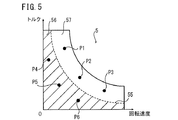
図5は、制御部31が保持する関係図5の一例を示すグラフである。図5に示すように、関係図5は、回転機200のトルクと回転速度との関係を示す。関係図5において、ハッチングの領域56は、回転機200が低出力で駆動することを示す。無地の領域57は、回転機200が高出力で駆動することを示す。
{1.4. Relationship diagram}
FIG. 5 is a graph illustrating an example of the relationship diagram 5 held by the
領域56と領域57との境界線55は、回転機200が定格出力で駆動するときのトルクと回転速度との関係を示す。回転機200が定格出力よりも大きい出力で駆動する場合、回転機200は高出力状態であり、回転機200が定格出力以下で駆動する場合、回転機200は、低出力状態にある。つまり、領域56で示される回転機200の出力は、領域57で示される回転機200の出力よりも小さい。
A
出力判断部35は、出力指令49で指定される駆動位置が、領域56及び57のどちらに存在するかを判断する。駆動位置は、トルク指令47で指定された指定トルク値と回転速度指令48で指定された指定回転速度値とにより定まる関係図5上の位置である。具体的には、出力判断部35は、駆動位置が領域57内の点P1〜P3のいずれかである場合、回転機200を高出力で駆動させると判断する。一方、出力判断部35は、駆動位置が領域56内の点P4〜P6のいずれかである場合、回転機200を低出力で駆動させると判断する。
The
{2.回転機制御装置3の動作}
図6を参照しながら、回転機制御装置3の動作を説明する。図6は、制御部31の動作を示すフローチャートである。以下、図1に示す構成が、自動車に搭載されていると仮定する。
{2. Operation of Rotating Machine Control Device 3}
The operation of the rotating machine control device 3 will be described with reference to FIG. FIG. 6 is a flowchart showing the operation of the
図6に示すように、制御部31は、自動車のMPU(Micro Processing Unit。図示省略)から出力指令49を取得する(ステップS11)。制御部31は、出力指令49から指定トルク値及び指定回転速度値を抽出する。
As shown in FIG. 6, the
出力判断部35は、指定トルク値と、指定回転速度値と、関係図5とを参照して、回転機200を高出力で駆動させるか低出力で駆動させるかを上述した方法によって判断する(ステップS12)。
The
制御部31は、回転機200を高出力で駆動させる場合(ステップS12でYes)、ステップS13〜S15を実行する。一方、制御部31は、回転機200を低出力で駆動させる場合(ステップS12でNo)、ステップS16〜S18を実行する。
{2.1.高出力で駆動させる場合(ステップS13〜S15)}
出力判断部35は、回転機200を高出力で駆動させることを示す指示信号43aを、電圧調整部32及びパルス信号生成部36に供給する(ステップS13)。電圧調整部32は、供給される指示信号43aに応じて、直流電圧Vcを直流電圧V1に調整し、その調整した直流電圧V1をインバータ34に供給する。
{2.1. When driving at high output (steps S13 to S15)}
The
電圧調整部32は、直流電圧V1の電圧を検出して電圧値46を制御部31に供給する。制御部31は、指示信号43aの他に、供給された電圧値46に基づいて、直流電圧V1の調整を指示する指示信号を電圧調整部32に出力する。この処理は、後述するステップS16でも同様である。
The voltage adjustment unit 32 detects the voltage of the DC voltage V <b> 1 and supplies a
パルス信号生成部36は、指示信号43aに応じて、回転機200を高出力で駆動させるためのパルス信号51を、指定トルク値及び指定回転速度値に基づいて生成する(ステップS14)。パルス信号生成部36は、その生成したパルス信号51をスイッチング信号生成部37に供給する。
In response to the
図7は、パルス信号51の一例を示す図である。図7において、パルス信号51と交流電圧Vd1の1周期との対応を示すために、交流電圧Vd1を示している。図7に示すように、パルス信号51の振幅は、A1で一定である。交流電圧Vd1の1周期あたりにおけるパルス信号51のパルス幅は、指定トルク値及び指定回転速度値により定まる駆動位置に応じて変化する。
FIG. 7 is a diagram illustrating an example of the
パルス信号生成部36は、交流電圧Vd1の電流値44a及び電圧値44bの供給をインバータ34から受け、回転速度45の供給を回転機200から受ける。なお、回転機200内に設けられたレゾルバ、エンコーダ等のセンサを設けることにより、回転速度45を検出することができる。あるいは、回転機200内のインダクタンスや誘起電圧の変化を検出し、検出結果に基づいて回転速度45を計算してもよい。パルス信号生成部36は、供給された電流値44a及び電圧値44bに基づいて、回転機200におけるトルクを算出する。パルス信号生成部36は、算出したトルク及び回転速度45に基づいて、出力指令49で指定された駆動条件で回転機200が回転するように、パルス信号51のパルス幅を調整する。この処理は、後述するステップS17でも同様である。
The pulse signal generator 36 receives supply of the
スイッチング信号生成部37は、パルス信号生成部36から供給されるパルス信号51に基づいて、スイッチング信号41を生成し(ステップS15)、その生成したスイッチング信号41をインバータ34に供給する。
The switching signal generator 37 generates a switching signal 41 based on the
インバータ34は、供給されたスイッチング信号41に基づいて内部のスイッチング素子のオンオフを切り替えることにより、電圧調整部32から供給される直流電圧V1から交流電圧Vd1を生成する。回転機200は、生成された交流電圧Vd1により、高出力で駆動する。
The
{2.2.低出力で駆動させる場合(ステップS16〜S18)}
出力判断部35は、回転機200を低出力で駆動させることを示す指示信号43bを、電圧調整部32及びパルス信号生成部36に供給する(ステップS16)。電圧調整部32は、供給される指示信号43bに応じて、直流電圧Vcを直流電圧V2(V2<V1)に調整し、その調整した直流電圧V2をインバータ34に供給する。
{2.2. When driving at low output (steps S16 to S18)}
The
パルス信号生成部36は、指示信号43bに応じて、ステップS14における方法と同じ方法により、回転機200を低出力で駆動させるためのパルス信号52を指定トルク値及び指定回転速度値に基づいて生成する(ステップS17)。パルス信号生成部36は、その生成したパルス信号52を、スイッチング信号生成部37に供給する。
The pulse signal generation unit 36 generates a
図8は、パルス信号52の一例を示す図である。また、図8において、図7と同様の理由により交流電圧Vd2を示している。図8に示すように、パルス信号52の振幅は、A2で一定である。振幅A2は振幅A1よりも小さい。また、交流電圧Vd2の1周期あたりにおけるパルス信号52のパルス幅は、指定トルク値及び指定回転速度値により定まる駆動位置により変化する。
FIG. 8 is a diagram illustrating an example of the
スイッチング信号生成部37は、パルス信号生成部36から供給されるパルス信号52に基づいて、スイッチング信号42を生成し(ステップS18)、その生成したスイッチング信号42をインバータ34に供給する。
The switching signal generator 37 generates a switching signal 42 based on the
インバータ34は、供給されたスイッチング信号42に基づいて内部のスイッチング素子のオンオフを切り替えることにより、電圧調整部32から供給される直流電圧V2から交流電圧Vd2を生成する。回転機200は、生成された交流電圧Vd2により、低出力で駆動する。
The
ステップS15又はS18の後に、制御部31は、ステップS11に戻り、新たな出力指令49に基づいて、図6に示す処理を繰り返す。
After step S15 or S18, the
{3.損失の抑制}
回転機制御装置3を用いることにより、回転機200の低出力駆動時における損失の増加を抑制することができる。以下、その理由を説明する。
{3. Loss suppression}
By using the rotating machine control device 3, an increase in loss when the
最初に、図9を参照しながら、回転機200で発生する損失について説明する。図9は、回転機200を回転機制御装置3により高出力で駆動させた場合における、回転機200のB−Hカーブの一例を示すグラフである。図9に示すように、複数のマイナーループ61bが、ヒステリシスループ61a上に存在している。なお、図9において、一部のマイナーループ61bの符号の表示を省略している。
Initially, the loss which generate | occur | produces in the
ヒステリシスループ61aは、交流電圧Vd1が理想的な正弦波である場合に描かれる。この場合、マイナーループ61bは発生しない。ヒステリシスループ61aの面積は、回転機200が交流電圧Vd1により駆動する場合に発生する磁気エネルギーであり、回転機200で発生する熱エネルギーに相当する。
The
マイナーループ61bは、交流電圧Vd1が高周波成分を含む場合に、ヒステリシスループ61a上に発生する。交流電圧Vd1は、インバータ34内のスイッチング素子のオンオフを切り替えることにより直流電圧Vcから生成される。従って、交流電圧Vd1は、実際には理想的な正弦波とならず、高周波成分を含む。
The
高周波成分は、回転機200で発生する渦電流損の原因となる。高周波成分が大きくなるにつれて、渦電流損も大きくなる。このため、交流電圧Vd1に含まれる高周波成分は少ない方が望ましい。
The high frequency component causes eddy current loss generated in the
次に、回転機200が高出力で駆動するときのB−Hカーブ(図9)を、低出力で駆動するときのB−Hカーブと比較する。図10は、回転機200を回転機制御装置3により低出力で駆動させた場合における、回転機200のB−Hカーブの一例を示すグラフである。
Next, the BH curve (FIG. 9) when the
図10においても、マイナーループ61bが、ヒステリシスループ61a上に発生している。しかし、図10に示すマイナーループ61bのサイズは、図9に示すB−Hカーブと比較して大きく変化していない。つまり、回転機制御装置3を用いることにより、回転機200が低出力で駆動する場合であっても、渦電流損が増加してないことが分かる。
Also in FIG. 10, the
図11は、従来のPWM方式により回転機200を低出力で駆動させた場合におけるパルス信号53を示す図である。図12は、パルス信号53を使用して回転機200を駆動させたときのB−Hカーブである。
FIG. 11 is a diagram showing a
図11において、パルス信号53の振幅をA1としている。1周期あたりのパルス信号53の数は、1周期あたりのパルス信号51の数と同じである。図12に示すヒステリシスループ61aは、図9、図10に示すヒステリシスループ61aと同一である。従来のPWM方式では、回転機200の出力に関係なく振幅が一定である。従って、回転機200を低出力で駆動させるためには、パルス信号53のパルス幅を小さくする必要がある。パルス信号53のパルス幅が小さくなるにつれて、パルス信号53に含まれる高周波成分が増加する。この結果、図12に示すように、ヒステリシスループ61a上に現れるマイナーループ61bのサイズは、パルス信号53のパルス幅が小さくなるにつれて逆に大きくなる。
In FIG. 11, the amplitude of the
従って、従来のPWM方式により回転機200を駆動した場合、低出力で駆動するときの渦電流損が増加する。
Therefore, when the
これに対して、回転機制御装置3を使用した場合、低出力駆動時におけるマイナーループ61bのサイズの増加を抑制することができる。上述のように、パルス信号52のパルス幅は、パルス信号51のパルス幅よりも大きいため、交流電圧Vd2に含まれる高周波成分が抑制される。また、直流電圧V2が直流電圧V1よりも小さいため、交流電圧Vd2の最大振幅は、V2であり、交流電圧Vd1の最大振幅(V1)よりも小さい。この結果、交流電圧Vd2に含まれる高周波成分の振幅が抑制される。これらの要因により、マイナーループ61bのサイズが抑制されるため、低出力で駆動するときの損失の増加を抑制することができる。
On the other hand, when the rotating machine control device 3 is used, an increase in the size of the
また、回転機制御装置3を使用することにより、回転機200が低出力で駆動するときの応答性を向上させることができる。従来のPAM方式において、低出力で駆動させるためにパルス信号の振幅を低下させた場合、回転機200に流れる電流が増加し、応答性が低下するという問題が生じる。本実施の形態において、電圧調整部32は、回転機200を低出力で駆動させるときに、高出力で駆動させる際に用いられる直流電圧V1よりも小さい直流電圧V2をインバータ34に供給する。しかし、パルス信号52のパルス幅をパルス信号51のパルス幅よりも大きくすることにより、交流電圧Vd2を大きくすることができる。この結果、回転機制御装置3は、低出力駆動時における電流容量を、従来のPAM方式よりも小さくすることができる。従って、回転機制御装置3は、回転機200が低出力で駆動する場合における応答性を向上させることができる。
Further, by using the rotating machine control device 3, it is possible to improve the responsiveness when the
以上説明したように、回転機制御装置3は、回転機200を低出力で駆動させる場合に用いられるパルス信号52のパルス幅を、高出力で駆動させる場合に用いられるパルス信号51のパルス幅よりも大きくする。さらに、回転機制御装置3は、パルス信号52の振幅をパルス信号51の振幅よりも小さくする。パルス信号52のパルス幅及び振幅を上記のように制御することにより、回転機200を低出力で駆動させるときの損失の増加を抑制することができる。このため、パルス信号51の面積の合計値とパルス信号52の面積の合計値とは、必ずしも一致していなくてもよい。
As described above, the rotating machine control device 3 uses the pulse width of the
{4.関係図5の変形例}
上記の実施の形態では、回転機200が低出力で駆動することを示す領域56と高出力で駆動することを示す領域57との境界線55が、回転機200の定格出力により定まる例を説明した。しかし、境界線55は、これに限られず、低出力で駆動することを示す領域56と高出力で駆動することを示す領域57とを区分するものであればよい。
{4. Modification of Relationship Diagram 5}
In the above embodiment, an example in which the
図13A及び図13Bは、関係図5における境界線の変形例を示す図である。図13A及び図13Bにおいて、境界線55a及び55bを一点鎖線で示す。領域56及び57は、境界線55aにより区分されてもよいし、境界線55bにより区分されてもよい。領域56は、境界線55a又は55bよりも下側の領域であり、領域57は、境界線55a又は55bよりも上側の領域である。
13A and 13B are diagrams showing a modification of the boundary line in the relationship diagram 5. In FIGS. 13A and 13B, the
図13A及び図13Bにおいて、境界線55、55a、及び55bの位置関係を示すために、境界線55を示している。境界線55aの変曲点Faは、境界線55上に存在する。境界線55a及び55bは、境界線55bにおける変曲点Fbの回転速度Xbよりも大きい領域で一致する。
13A and 13B, the
上記実施の形態では、回転機200の駆動状態を、指定トルク値及び指定回転速度値に基づいて2段階(低出力、高出力)に区分する例を説明したが、これに限らない。図14A〜図14Dに示すように、回転機200の駆動状態を4段階に区分してもよい。
In the above-described embodiment, the example in which the driving state of the
回転機200の駆動状態は、領域71〜74のいずれかに分類される。図14A〜14Dにおいて、領域71及び74をハッチングで示し、領域72及び73を無地で示す。図14Aにおいて、領域71〜74は、境界線55a及び59aによって区分される。図14Bにおいて、領域71〜74は、境界線55a及び59bによって区分される。図14Cにおいて、領域71〜74は、境界線55b及び59aによって区分される。図14Dにおいて、領域71〜74は、境界線55b及び59bによって区分される。
The driving state of the
境界線59a及び59bは、関係図5の縦軸に平行な直線であり、境界線59aの回転速度値は、境界線59bの回転速度値よりも小さい。
The
図15は、図14A及び図14Bに示す領域71〜74における指定トルク値と指定回転速度値との関係を示す図である。図15において、トルクが高い/低いは、境界線55a又は55bにより決定される。回転速度が高い/低いは、境界線59a又は59bにより決定される。
FIG. 15 is a diagram showing the relationship between the designated torque value and the designated rotational speed value in the
領域71〜74における回転機200の駆動状態は、以下の通りである。領域71は、回転速度が低く、トルクが高い領域である。例えば、回転機200が動力源として自動車に搭載された場合、領域71は、停止している自動車が急発進する場合に対応する。領域72は、回転速度及びトルクがともに低い領域であり、一般道路で自動車が一定速度で走行する場合に対応する。領域73は、回転速度及びトルクがともに高い領域であり、高速道路を走行中の自動車がさらに加速する場合に対応する。領域74は、回転速度が高く、トルクが低い領域であり、自動車が高速道路で一定の速度で走行する場合に対応する。
The driving state of the
以下、図14A〜図14Dのいずれか1つの関係図5を用いる場合における制御部31の動作を説明する。
Hereinafter, the operation of the
出力判断部35は、指定トルク値及び指定回転速度値により定まる駆動位置に基づいて、インバータ4の出力電圧を決定する。具体的には、出力判断部35は、領域71〜74のうち駆動位置が存在する領域を特定し、領域71〜74に応じたインバータ4の出力電圧Vr1〜Vr4のうち特定した領域に対応する出力電圧を選択する。
The
パルス信号生成部36は、出力判断部35により選択された出力電圧に対応するパルス信号を生成する。つまり、パルス信号生成部36により生成されるパルス信号の振幅及びパルス幅は、駆動位置が存在する領域に応じて変化する。
The pulse signal generation unit 36 generates a pulse signal corresponding to the output voltage selected by the
電圧調整部32は、領域71〜74に応じたインバータ4の出力電圧Vr1〜Vr4に対応する直流電圧を生成する。つまり、インバータ4に供給される直流電圧は、駆動位置が存在する領域に応じて変化する。
Voltage adjusting unit 32 generates a DC voltage corresponding to output voltages Vr <b> 1 to Vr <b> 4 of inverter 4 corresponding to
このように、回転機200の駆動状態を4つに区分し、それぞれの駆動状態に応じてパルス信号の振幅及びパルス幅を変化させた場合、上記実施の形態のように駆動状態を2段階で評価するときよりも、パルス信号のパルス幅を比較的大きい状態に保つことができる。その結果、パルス信号に含まれる高周波成分を抑制することができ、回転機200が低出力で駆動するときの損失の増加を抑制することができる。
As described above, when the driving state of the
つまり、回転機制御装置3は、関係図5を2つ以上の領域に区分し、駆動位置がどの領域に存在するかに応じて、パルス信号の振幅及びパルス幅を変化させればよい。 That is, the rotating machine control device 3 may divide the relationship diagram 5 into two or more regions and change the amplitude and pulse width of the pulse signal according to which region the drive position is present.
また、制御部31は、領域71〜74を区分する境界線を変更できるようにしてもよい。具体的には、制御部31が境界線55a及び55bのいずれか一方を選択し、境界線59a及び59bのいずれか一方を選択する。また、境界線の変更は、各領域71〜74の使用頻度に応じて変更すると良い。
Moreover, you may enable it to change the boundary line which divides the areas 71-74. Specifically, the
制御部31は、駆動位置が各領域に存在する頻度に応じて、境界線を選択すればよい。例えば、制御部31が図14Aに示す関係図を選択している場合を想定する。駆動位置が領域72に存在した回数よりも領域71に存在した回数が極端に大きい場合、制御部31は、境界線55bを選択して、図14Cに示す関係図5を新たに使用する。これにより、領域72が広くなるため、駆動位置が領域72に存在する頻度が高くなる。同様に、制御部31は、駆動位置が領域71及び領域73に存在する頻度に応じて、境界線59a及び59bのいずれかを選択すればよい。
The
あるいは、境界線は、モータの仕様、電流の最適値(銅損が最小となる電流値)などに応じて選択されてもよい。 Alternatively, the boundary line may be selected according to the motor specifications, the optimum current value (current value that minimizes copper loss), and the like.
{その他の変形例}
上記実施の形態では、制御部31が関係図5として図5に示すグラフを保持する例を説明したが、これに限られない。例えば、制御部31は、境界線55を示すデータを保持してもよい。この場合、出力判断部35は、駆動位置の回転速度を基準にして、駆動位置が境界線55よりも上に位置するか下に位置するかを判断すればよい。駆動位置が境界線55より上に位置する場合、出力判断部35は、回転機200を高出力で駆動させると判断する。逆に、駆動位置が境界線55以下に位置する場合、出力判断部35は、回転機200を低出力で駆動させると判断する。
{Other variations}
In the above embodiment, the example in which the
あるいは、制御部31は、領域56及び57の各々の範囲を示す範囲データを保持していてもよい。この場合、出力判断部35は、範囲データを参照して、駆動位置が領域56及び57のどちらに含まれるかを判断すればよい。
Alternatively, the
上記実施の形態では、コンデンサ33が、電圧調整部32とインバータ34との間に設けられる例を説明したが、これに限られない。コンデンサ33は、コンバータ2と電圧調整部32との間に設けられてもよい。これにより、直流電圧Vcに含まれるノイズを低減することができる。あるいは、コンデンサ33は、電圧調整部32とインバータ34との間に設けられ、コンデンサ33は、コンバータ2と電圧調整部32との間に設けられてもよい。
In the above embodiment, the example in which the capacitor 33 is provided between the voltage adjustment unit 32 and the
また、エンジンに取り付けられた回転機を、上記実施の形態で説明した回転機制御装置3を用いて制御してもよい。図16は、回転機制御装置3の一使用例を示す図である。図16に示すエンジンユニット500は、例えば、自動車の動力源として使用され、回転機制御装置3と、回転機200と、エンジン400とを備える。
Moreover, you may control the rotary machine attached to the engine using the rotary machine control apparatus 3 demonstrated in the said embodiment. FIG. 16 is a diagram illustrating an example of use of the rotating machine control device 3. An
回転機200は、エンジン400の回転軸に連結される。回転機200は、エンジン400が駆動を開始する際の動力を供給する。また、回転機200は、エンジン400の回転軸の回転に応じて発電し、発電した電力を図示しないバッテリと負荷に供給する。なお、回転機200の回転軸は、エンジン400の回転軸にギアなどを介して間接的に連結されてもよい。回転機制御装置3は、上記の実施の形態と同様に、回転機200を制御する。
The
なお、上記実施の形態で説明した制御部31は、LSIなどの半導体装置により個別に1チップ化されても良いし、制御部31の一部又は全部を含むように1チップ化されてもよい。
The
また、集積回路化の手法はLSIに限るものではなく、専用回路又は汎用プロセサで実現してもよい。LSI製造後に、プログラムすることが可能なFPGA(Field Programmable Gate Array)や、LSI内部の回路セルの接続や設定を再構成可能なリコンフィギュラブル・プロセッサを利用しても良い。 Further, the method of circuit integration is not limited to LSI, and implementation with a dedicated circuit or a general-purpose processor is also possible. An FPGA (Field Programmable Gate Array) that can be programmed after manufacturing the LSI or a reconfigurable processor that can reconfigure the connection and setting of circuit cells inside the LSI may be used.
また、制御部31の一部または全部は、プログラムにより実現されるものであってもよい。そして、制御部31の処理の一部または全部は、コンピュータにおいて、中央演算装置(CPU)により行われる。また、それぞれの処理を行うためのプログラムは、ハードディスク、ROMなどの記憶装置に格納されており、ROMにおいて、あるいはRAMに読み出されて実行される。
Moreover, a part or all of the
また、上記実施形態の各処理をハードウェアにより実現してもよいし、ソフトウェア(OS(オペレーティングシステム)、ミドルウェア、あるいは、所定のライブラリとともに実現される場合を含む。) により実現してもよい。さらに、ソフトウェアおよびハードウェアの混在処理により実現しても良い。 In addition, each process of the above embodiment may be realized by hardware, or may be realized by software (including a case where it is realized together with an OS (operating system), middleware, or a predetermined library). Further, it may be realized by mixed processing of software and hardware.
以上、本発明の実施の形態を説明したが、上述した実施の形態は本発明を実施するための例示に過ぎない。よって、本発明は上述した実施の形態に限定されることなく、その趣旨を逸脱しない範囲内で上述した実施の形態を適宜変形して実施することが可能である。 While the embodiments of the present invention have been described above, the above-described embodiments are merely examples for carrying out the present invention. Therefore, the present invention is not limited to the above-described embodiment, and can be implemented by appropriately modifying the above-described embodiment without departing from the spirit thereof.
1 交流電源
2 コンバータ
3 回転機制御装置
31 制御部
32 電圧調整部
33 コンデンサ
34 インバータ
35 出力判断部
36 パルス信号生成部
37 スイッチング信号生成部
100 駆動装置
200 モータ・ジェネレータ(回転機)
DESCRIPTION OF
Claims (4)
前記インバータに第1の直流電圧と前記第1の直流電圧よりも低い第2の直流電圧のいずれか一方を供給し、前記第1の直流電圧が前記インバータに供給されるときに第1のパルス幅変調方式に基づくスイッチング信号を前記インバータに供給し、前記第2の直流電圧が前記インバータに供給されるときに第2のパルス幅変調方式に基づくスイッチング信号を前記インバータに供給する制御装置とを備え、
前記第1のパルス幅変調方式では、第1のパルス信号が用いられ、
前記第2のパルス幅変調方式では、前記第1のパルス信号の振幅よりも小さい振幅と前記第1のパルス信号のパルス幅よりも大きいパルス幅とを有する第2のパルス信号が用いられ、
前記インバータから出力される交流電圧の1周期あたりの前記第1のパルス信号の面積の合計値は、前記1周期あたりの前記第2のパルス信号の面積の合計値と同じである回転機制御装置。 An inverter;
Either one of a first DC voltage and a second DC voltage lower than the first DC voltage is supplied to the inverter, and a first pulse is supplied when the first DC voltage is supplied to the inverter. A control device for supplying a switching signal based on a width modulation method to the inverter and supplying a switching signal based on a second pulse width modulation method to the inverter when the second DC voltage is supplied to the inverter; Prepared,
In the first pulse width modulation method, a first pulse signal is used,
In the second pulse width modulation method, a second pulse signal having an amplitude smaller than the amplitude of the first pulse signal and a pulse width larger than the pulse width of the first pulse signal is used.
The total value of the area of the first pulse signal per cycle of the AC voltage output from the inverter is the same as the total value of the area of the second pulse signal per cycle. .
前記制御装置は、
回転機の第1の出力に対応する第1の指示信号と、前記第1の出力よりも小さい第2の出力に対応する第2の指示信号とのいずれかを出力し、前記回転機が第1の出力で駆動する場合、前記第1のパルス信号に基づくスイッチング信号を前記インバータに供給し、前記回転機が第2の出力で駆動する場合、前記第2のパルス信号に基づくスイッチング信号を前記インバータに供給する制御部と、
前記第1の指示信号を前記制御部から受けた場合、入力直流電圧を前記第1の直流電圧に調整し、前記第2の指示信号を前記制御部から受けた場合、前記入力直流電圧を前記第2の直流電圧に調整する電圧調整部とを備える回転機制御装置。 The rotating machine control device according to claim 1,
The controller is
One of a first instruction signal corresponding to the first output of the rotating machine and a second instruction signal corresponding to a second output smaller than the first output is output, and the rotating machine outputs the first instruction signal. When driving with an output of 1, the switching signal based on the first pulse signal is supplied to the inverter, and when the rotating machine is driven with a second output, the switching signal based on the second pulse signal is A control unit for supplying to the inverter;
When the first instruction signal is received from the control unit, the input DC voltage is adjusted to the first DC voltage, and when the second instruction signal is received from the control unit, the input DC voltage is A rotating machine control device comprising: a voltage adjusting unit that adjusts to a second DC voltage.
前記制御部は、前記回転機のトルクと回転速度との関係を示す関係図を保持し、前記関係図と、前記回転機の駆動条件を指示する出力指令に含まれるトルク値と、前記出力指令に含まれる回転速度とを参照して前記第1又は第2の指示信号を出力し、前記出力指令に含まれるトルク値及び回転速度に基づいて、前記第1又は第2のパルス信号を生成する回転機制御装置。 The rotating machine control device according to claim 2,
The control unit holds a relationship diagram showing a relationship between torque and rotation speed of the rotating machine, the relationship diagram, a torque value included in an output command instructing a driving condition of the rotating machine, and the output command The first or second instruction signal is output with reference to the rotational speed included in the output signal, and the first or second pulse signal is generated based on the torque value and the rotational speed included in the output command. Rotating machine control device.
前記回転機制御装置により制御される回転機と、
前記回転機の回転軸に連結された回転軸を含むエンジンとを備えるエンジンユニット。
The rotating machine control device according to any one of claims 1 to 3,
A rotating machine controlled by the rotating machine control device;
An engine unit including a rotation shaft coupled to a rotation shaft of the rotating machine.
Priority Applications (1)
| Application Number | Priority Date | Filing Date | Title |
|---|---|---|---|
| JP2013204961A JP6146615B2 (en) | 2013-09-30 | 2013-09-30 | Rotating machine control device |
Applications Claiming Priority (1)
| Application Number | Priority Date | Filing Date | Title |
|---|---|---|---|
| JP2013204961A JP6146615B2 (en) | 2013-09-30 | 2013-09-30 | Rotating machine control device |
Publications (2)
| Publication Number | Publication Date |
|---|---|
| JP2015070740A JP2015070740A (en) | 2015-04-13 |
| JP6146615B2 true JP6146615B2 (en) | 2017-06-14 |
Family
ID=52836926
Family Applications (1)
| Application Number | Title | Priority Date | Filing Date |
|---|---|---|---|
| JP2013204961A Active JP6146615B2 (en) | 2013-09-30 | 2013-09-30 | Rotating machine control device |
Country Status (1)
| Country | Link |
|---|---|
| JP (1) | JP6146615B2 (en) |
Family Cites Families (3)
| Publication number | Priority date | Publication date | Assignee | Title |
|---|---|---|---|---|
| JPH10225167A (en) * | 1997-02-06 | 1998-08-21 | Zexel Corp | Drive controller for brushless motor |
| JP4802849B2 (en) * | 2006-05-09 | 2011-10-26 | トヨタ自動車株式会社 | Motor drive device |
| JP5682157B2 (en) * | 2010-06-25 | 2015-03-11 | 株式会社島津製作所 | Motor drive device and pump system for vacuum pump |
-
2013
- 2013-09-30 JP JP2013204961A patent/JP6146615B2/en active Active
Also Published As
| Publication number | Publication date |
|---|---|
| JP2015070740A (en) | 2015-04-13 |
Similar Documents
| Publication | Publication Date | Title |
|---|---|---|
| US9431951B2 (en) | Direct torque control motor controller with transient current limiter | |
| US8233294B2 (en) | Method and system for controlling a power converter system connected to a DC-bus capacitor | |
| US9444384B2 (en) | Direct torque control motor controller with transient current limiter | |
| US9407189B2 (en) | Direct torque control motor controller with torque ripple reduction | |
| WO2014192373A1 (en) | Power conversion device, power conversion device control method, rotation sensorless control device, and rotation sensorless control device control method | |
| JP5434696B2 (en) | Vehicle generator | |
| US9893657B2 (en) | Electric motor mode control | |
| JP2008236932A (en) | Motor drive device and electrical apparatus using this | |
| WO2014006820A1 (en) | Motor driving device | |
| US20120286705A1 (en) | Apparatus and method for controlling rotary electric machine | |
| WO2018221628A1 (en) | Motor current control device and motor current control method | |
| JP6404864B2 (en) | Switched reluctance motor controller | |
| CN107453674B (en) | Motor control device and motor control method | |
| US9871485B2 (en) | Stepper motor driver circuit | |
| JP6146615B2 (en) | Rotating machine control device | |
| CN109560727B (en) | Multiphase DC brushless motor driving circuit | |
| JP6329504B2 (en) | Motor drive control device and motor drive control method | |
| JP7354962B2 (en) | Inverter control device and program | |
| JP6961096B2 (en) | Inverter device | |
| JP5298452B2 (en) | Motor inverter control device and motor control method | |
| JP5408978B2 (en) | Ultrasonic motor speed control device and speed control method | |
| JP2015033278A (en) | Motor drive unit | |
| JP2007236135A (en) | Regenerative controller for switched reluctance motor | |
| JP2018019528A (en) | Switched reluctance motor controller | |
| JP2004254441A (en) | Motor controller |
Legal Events
| Date | Code | Title | Description |
|---|---|---|---|
| A621 | Written request for application examination |
Free format text: JAPANESE INTERMEDIATE CODE: A621 Effective date: 20160809 |
|
| A977 | Report on retrieval |
Free format text: JAPANESE INTERMEDIATE CODE: A971007 Effective date: 20170412 |
|
| TRDD | Decision of grant or rejection written | ||
| A01 | Written decision to grant a patent or to grant a registration (utility model) |
Free format text: JAPANESE INTERMEDIATE CODE: A01 Effective date: 20170420 |
|
| A61 | First payment of annual fees (during grant procedure) |
Free format text: JAPANESE INTERMEDIATE CODE: A61 Effective date: 20170503 |
|
| R150 | Certificate of patent or registration of utility model |
Ref document number: 6146615 Country of ref document: JP Free format text: JAPANESE INTERMEDIATE CODE: R150 |
|
| R250 | Receipt of annual fees |
Free format text: JAPANESE INTERMEDIATE CODE: R250 |
|
| R250 | Receipt of annual fees |
Free format text: JAPANESE INTERMEDIATE CODE: R250 |
|
| R250 | Receipt of annual fees |
Free format text: JAPANESE INTERMEDIATE CODE: R250 |
|
| R250 | Receipt of annual fees |
Free format text: JAPANESE INTERMEDIATE CODE: R250 |
|
| R250 | Receipt of annual fees |
Free format text: JAPANESE INTERMEDIATE CODE: R250 |