JP6138293B1 - Road surface undulation estimation device and road surface undulation estimation method - Google Patents
Road surface undulation estimation device and road surface undulation estimation method Download PDFInfo
- Publication number
- JP6138293B1 JP6138293B1 JP2016007733A JP2016007733A JP6138293B1 JP 6138293 B1 JP6138293 B1 JP 6138293B1 JP 2016007733 A JP2016007733 A JP 2016007733A JP 2016007733 A JP2016007733 A JP 2016007733A JP 6138293 B1 JP6138293 B1 JP 6138293B1
- Authority
- JP
- Japan
- Prior art keywords
- road surface
- detection
- unit
- vehicle
- camera
- Prior art date
- Legal status (The legal status is an assumption and is not a legal conclusion. Google has not performed a legal analysis and makes no representation as to the accuracy of the status listed.)
- Active
Links
- 238000000034 method Methods 0.000 title claims abstract description 51
- 238000001514 detection method Methods 0.000 claims abstract description 150
- 238000009434 installation Methods 0.000 claims abstract description 120
- 238000006243 chemical reaction Methods 0.000 claims abstract description 71
- 238000004364 calculation method Methods 0.000 claims abstract description 45
- 230000002093 peripheral effect Effects 0.000 claims abstract description 21
- 230000002123 temporal effect Effects 0.000 claims description 5
- 238000010586 diagram Methods 0.000 description 14
- 230000033001 locomotion Effects 0.000 description 14
- 230000036962 time dependent Effects 0.000 description 5
- 230000014509 gene expression Effects 0.000 description 3
- 244000089409 Erythrina poeppigiana Species 0.000 description 2
- 235000009776 Rathbunia alamosensis Nutrition 0.000 description 2
- 230000004888 barrier function Effects 0.000 description 2
- 230000000694 effects Effects 0.000 description 2
- 230000015556 catabolic process Effects 0.000 description 1
- 238000006731 degradation reaction Methods 0.000 description 1
- 239000000284 extract Substances 0.000 description 1
- 238000003384 imaging method Methods 0.000 description 1
- 238000005259 measurement Methods 0.000 description 1
- 230000003449 preventive effect Effects 0.000 description 1
- 230000003252 repetitive effect Effects 0.000 description 1
- 239000004576 sand Substances 0.000 description 1
- 239000000725 suspension Substances 0.000 description 1
Images


Classifications
-
- B—PERFORMING OPERATIONS; TRANSPORTING
- B60—VEHICLES IN GENERAL
- B60W—CONJOINT CONTROL OF VEHICLE SUB-UNITS OF DIFFERENT TYPE OR DIFFERENT FUNCTION; CONTROL SYSTEMS SPECIALLY ADAPTED FOR HYBRID VEHICLES; ROAD VEHICLE DRIVE CONTROL SYSTEMS FOR PURPOSES NOT RELATED TO THE CONTROL OF A PARTICULAR SUB-UNIT
- B60W40/00—Estimation or calculation of non-directly measurable driving parameters for road vehicle drive control systems not related to the control of a particular sub unit, e.g. by using mathematical models
- B60W40/02—Estimation or calculation of non-directly measurable driving parameters for road vehicle drive control systems not related to the control of a particular sub unit, e.g. by using mathematical models related to ambient conditions
- B60W40/06—Road conditions
-
- G—PHYSICS
- G06—COMPUTING; CALCULATING OR COUNTING
- G06T—IMAGE DATA PROCESSING OR GENERATION, IN GENERAL
- G06T7/00—Image analysis
- G06T7/70—Determining position or orientation of objects or cameras
- G06T7/73—Determining position or orientation of objects or cameras using feature-based methods
-
- G—PHYSICS
- G06—COMPUTING; CALCULATING OR COUNTING
- G06V—IMAGE OR VIDEO RECOGNITION OR UNDERSTANDING
- G06V20/00—Scenes; Scene-specific elements
- G06V20/50—Context or environment of the image
- G06V20/56—Context or environment of the image exterior to a vehicle by using sensors mounted on the vehicle
- G06V20/588—Recognition of the road, e.g. of lane markings; Recognition of the vehicle driving pattern in relation to the road
-
- B—PERFORMING OPERATIONS; TRANSPORTING
- B60—VEHICLES IN GENERAL
- B60W—CONJOINT CONTROL OF VEHICLE SUB-UNITS OF DIFFERENT TYPE OR DIFFERENT FUNCTION; CONTROL SYSTEMS SPECIALLY ADAPTED FOR HYBRID VEHICLES; ROAD VEHICLE DRIVE CONTROL SYSTEMS FOR PURPOSES NOT RELATED TO THE CONTROL OF A PARTICULAR SUB-UNIT
- B60W2420/00—Indexing codes relating to the type of sensors based on the principle of their operation
- B60W2420/40—Photo, light or radio wave sensitive means, e.g. infrared sensors
- B60W2420/403—Image sensing, e.g. optical camera
-
- G—PHYSICS
- G06—COMPUTING; CALCULATING OR COUNTING
- G06T—IMAGE DATA PROCESSING OR GENERATION, IN GENERAL
- G06T2207/00—Indexing scheme for image analysis or image enhancement
- G06T2207/30—Subject of image; Context of image processing
- G06T2207/30248—Vehicle exterior or interior
- G06T2207/30252—Vehicle exterior; Vicinity of vehicle
- G06T2207/30256—Lane; Road marking
Landscapes
- Engineering & Computer Science (AREA)
- Physics & Mathematics (AREA)
- General Physics & Mathematics (AREA)
- Theoretical Computer Science (AREA)
- Multimedia (AREA)
- Mathematical Physics (AREA)
- Mechanical Engineering (AREA)
- Transportation (AREA)
- Automation & Control Theory (AREA)
- Computer Vision & Pattern Recognition (AREA)
- Traffic Control Systems (AREA)
- Length Measuring Devices By Optical Means (AREA)
- Image Processing (AREA)
- Measurement Of Optical Distance (AREA)
- Studio Devices (AREA)
Abstract
【課題】車両が走行する路面の起伏を推定することのできる路面起伏推定装置および路面起伏推定方法を得る。【解決手段】カメラから取得した車両周辺画像から規則物体を検出し、各規則物体の画像上での位置を、カメラ設置情報を用いて画像上から実空間上へ変換することで各規則物体の検出位置を計算し、各検出位置において隣り合う検出位置の検出間隔をそれぞれ計算し、各検出位置と、計算した各検出間隔と、規則物体の設置間隔とから、画像上から実空間上への変換計算上の路面に対する実際の路面の傾きを推定するように構成されている。【選択図】図1A road surface undulation estimation device and a road surface undulation estimation method capable of estimating the road surface undulation on which a vehicle travels are obtained. A regular object is detected from a vehicle peripheral image acquired from a camera, and the position of each regular object on the image is converted from the image to the real space using camera installation information. The detection position is calculated, and the detection intervals of the adjacent detection positions at each detection position are calculated. From each detection position, each calculated detection interval, and the installation interval of the regular object, from the image to the real space. The actual road surface inclination with respect to the road surface in the conversion calculation is estimated. [Selection] Figure 1
Description
本発明は、車両が走行する路面の起伏を推定する路面起伏推定装置および路面起伏推定方法に関するものである。 The present invention relates to a road surface undulation estimation device and a road surface undulation estimation method for estimating the undulation of a road surface on which a vehicle travels.
車両に搭載されているセンサを用いて、車両周辺の対象物を検知することで、事前に危険を回避する予防安全システムの提案が近年増加している。このようなシステムでは、対象物の位置を高精度で求めなければならない。 In recent years, there has been an increase in proposals of preventive safety systems that avoid danger in advance by detecting objects around the vehicle using sensors mounted on the vehicle. In such a system, the position of the object must be determined with high accuracy.
ここで、車両周辺センシングのデバイスとしてカメラを用いる場合、対象物の位置を高精度に算出するためには、車載カメラの車両への取り付け状態、すなわち、路面に対する車載カメラの設置角度を正確に校正することが重要となる。 Here, when a camera is used as the vehicle periphery sensing device, in order to calculate the position of the object with high accuracy, the mounting state of the in-vehicle camera on the vehicle, that is, the installation angle of the in-vehicle camera with respect to the road surface is accurately calibrated. It is important to do.
一般的には、出荷前に車載カメラを校正する時に、路面が水平または路面の傾斜が一定の場所で、路面を水平面と仮定し、その路面に対する車載カメラの設置角度を事前に求めておく。車両走行時に、車載カメラから取得したカメラ画像に映る路面上の対象物を検出し、その対象物の画像上での位置を求める。続いて、対象物の画像上での位置を、事前に求めた車載カメラの設置角度から、対象物の実空間での位置を求める。 In general, when calibrating an in-vehicle camera before shipment, it is assumed that the road surface is horizontal or the road surface is a horizontal plane, and the installation angle of the in-vehicle camera with respect to the road surface is obtained in advance. When the vehicle travels, an object on the road surface reflected in the camera image acquired from the in-vehicle camera is detected, and the position of the object on the image is obtained. Subsequently, the position of the object in the real space is obtained from the installation angle of the in-vehicle camera obtained in advance for the position of the object on the image.
なお、上記の手法では、事前に求めた車載カメラの設置角度と、車両の走行中の路面に対する車載カメラの設置角度とが一致することを前提としている。しかしながら、実環境において車両が走行する路面には起伏があるので、路面が水平面であるとは限らず、さらに、車両の走行場所によっては、路面の起伏が動的に変化する。そのため、実際には、事前に求めた車載カメラの設置角度と、車両の走行中の路面に対する車載カメラの設置角度とが一致するわけではない。したがって、上記の前提の下、対象物の実空間での位置を求めると、対象物の位置を検出する精度が低下する可能性があるという問題がある。 In the above method, it is assumed that the installation angle of the in-vehicle camera obtained in advance matches the installation angle of the in-vehicle camera with respect to the road surface while the vehicle is traveling. However, since the road surface on which the vehicle travels in an actual environment has undulations, the road surface is not necessarily a horizontal surface, and the road undulations dynamically change depending on the travel location of the vehicle. Therefore, in practice, the installation angle of the in-vehicle camera obtained in advance does not match the installation angle of the in-vehicle camera with respect to the road surface while the vehicle is traveling. Therefore, when the position of the object in real space is obtained under the above assumption, there is a problem that the accuracy of detecting the position of the object may be reduced.
このように、実環境において車両が走行する路面には起伏があることから、車両が走行する路面の起伏を推定する技術が必要である。なお、上記の問題点に対応する一例として、路面に存在する対象物の動き情報を用いて、路面に対する車載カメラの設置角度を車両の走行中にリアルタイムで校正する車載カメラ自動キャリブレーション装置(例えば、特許文献1参照)が提案されているが、その装置は、車両が走行する路面の起伏を推定するように構成されていない。 Thus, since the road surface on which the vehicle travels in an actual environment has undulations, a technique for estimating the undulation of the road surface on which the vehicle travels is necessary. As an example corresponding to the above-described problem, an in-vehicle camera automatic calibration device that calibrates the installation angle of the in-vehicle camera with respect to the road surface in real time while the vehicle is traveling (for example, using movement information of an object existing on the road surface) However, the apparatus is not configured to estimate the undulation of the road surface on which the vehicle travels.
上述したとおり、実環境において車両が走行する路面には起伏があることから、車両が走行する路面の起伏を推定する技術が必要である。 As described above, since the road surface on which the vehicle travels in an actual environment has undulations, a technique for estimating the undulation of the road surface on which the vehicle travels is necessary.
本発明は、上記のような課題を解決するためになされたものであり、車両が走行する路面の起伏を推定することのできる路面起伏推定装置および路面起伏推定方法を得ることを目的とする。 The present invention has been made to solve the above-described problems, and an object thereof is to obtain a road surface undulation estimation apparatus and a road surface undulation estimation method that can estimate the undulation of a road surface on which a vehicle travels.
本発明における路面起伏推定装置は、路面を走行する車両の周辺を撮像可能なように車両に搭載されたカメラによって撮像された車両周辺画像が入力される路面起伏推定装置であって、事前に求められたカメラ設置情報を記憶する記憶部と、カメラから取得した車両周辺画像から、路面に一定の設置間隔で設置されている規則物体を検出し、検出した各規則物体の画像上での位置を計算し、計算結果を位置情報として出力する対象物検出部と、対象物検出部から入力された位置情報と、記憶部から取得したカメラ設置情報とから、各規則物体の画像上での位置を、各規則物体の実空間での位置に変換し、変換結果を各規則物体の検出位置として出力する位置変換部と、位置変換部から入力された各検出位置において隣り合う検出位置の検出間隔をそれぞれ計算し、カメラのレンズ中心と各検出位置との位置関係から、レンズ中心と各検出位置とを通る各直線と、位置変換部による変換計算上の路面とがなす角をそれぞれ求め、位置変換部による変換計算上の路面に対する実際の路面の傾きを推定する路面推定部と、を備え、レンズ中心の位置をOとし、実際の路面に存在する各規則物体の実際の位置について、レンズ中心に最も近い位置をPt 0 とし、Pt 0 から近い順にPt 1 ,・・・Pt n+1 (ただし、nは1以上の整数)とし、各検出位置について、レンズ中心に最も近い位置をPd 0 とし、Pd 0 とPt 0 が一致していると仮定し、Pd 0 から近い順にPd 1 ,・・・Pd n+1 とし、各検出間隔について、隣り合うPd 0 ,Pd 1 の検出間隔をa 0 とし、a 0 から近い順にa 1 ,・・・,a n とし、規則物体の設置間隔をbとし、レンズ中心と各検出位置とを通る各直線と、位置変換部による変換計算上の路面とがなす角について、∠OPd 1 Pd 0 ,∠OPd 2 Pd 1 ,・・・,∠OPd n+1 Pd n とし、レンズ中心の変換計算上の路面からの高さをH 0 とし、変換計算上の路面と、各直線Pt 0 Pt 1 ,・・・,Pt n Pt n+1 とがなす角について、θ 0 ,・・・,θ n としたとき、路面推定部は、∠OPd 1 Pd 0 と、a 0 と、bとから、θ 0 を実際の路面の傾きとして推定し、∠OPd 2 Pd 1 ,・・・,∠OPd n+1 Pd n と、a 1 ,・・・,a n と、bと、H 0 と、θ 0 とから、θ 1 ,・・・,θ n を、実際の路面の傾きとして推定するものである。 A road surface undulation estimation device according to the present invention is a road surface undulation estimation device to which a vehicle periphery image captured by a camera mounted on a vehicle is input so that the periphery of the vehicle traveling on the road surface can be imaged. A regular object installed at a certain installation interval on the road surface from a storage unit for storing the obtained camera installation information and a vehicle peripheral image acquired from the camera, and the position of each detected regular object on the image is detected. The position on the image of each regular object is calculated from the object detection unit that calculates and outputs the calculation result as position information, the position information input from the object detection unit, and the camera installation information acquired from the storage unit. A position conversion unit that converts each regular object into a position in real space and outputs the conversion result as a detection position of each regular object; and between detection of adjacent detection positions at each detection position input from the position conversion unit Each calculated from the positional relationship between the lens center and the respective detection position of the camera, determined the respective straight lines passing through the lens center and the respective detection positions, on conversion calculation by the position converting unit road surface and the angle of each position A road surface estimation unit that estimates an inclination of an actual road surface with respect to a road surface in conversion calculation by the conversion unit, where the lens center position is O, and the actual center position of each regular object on the actual road surface the position closest to the Pt 0, Pt 1 in order close to the Pt 0, ··· Pt n + 1 ( where, n is an integer of 1 or more) and, for each detection position, the closest to the lens center and Pd 0, suppose Pd 0 and Pt 0 matches, pd 1 to order of proximity to the Pd 0, and ··· Pd n + 1, for each detection interval, the detection interval of Pd 0, Pd 1 adjacent to the a 0, a A 1 in this order close to 0, ..., and a n, the installation spacing rule object and is b, and the straight line passing through the lens center and the detection position, the road surface and the angle formed on the conversion calculation by the position conversion section ∠OPd 1 Pd 0 , ∠OPd 2 Pd 1 ,..., ∠OPd n + 1 Pd n, and the height of the lens center from the road surface in the conversion calculation is H 0 , When the angles formed by the straight lines Pt 0 Pt 1 ,..., Pt n Pt n + 1 are θ 0 ,..., Θ n , the road surface estimation unit performs ∠OPd 1 Pd 0 , a 0 , b from estimates as the slope of the actual road surface θ 0, ∠OPd 2 Pd 1, ···, and ∠OPd n + 1 Pd n, a 1, ···, and a n, and b, or H 0, From θ 0 , θ 1 ,..., θ n are estimated as actual road surface inclinations. .
また、本発明における路面起伏推定方法は、路面を走行する車両の周辺を撮像可能なように車両に搭載されたカメラによって撮像された車両周辺画像を用いて路面の起伏を推定する路面起伏推定方法であって、カメラから取得した車両周辺画像から、路面に一定の設置間隔で設置されている規則物体を検出し、検出した各規則物体の画像上での位置を計算し、計算結果を位置情報として出力する対象物検出ステップと、対象物検出ステップで出力された位置情報と、事前に求められたカメラ設置情報とから、各規則物体の画像上での位置を、各規則物体の実空間での位置に変換し、変換結果を各規則物体の検出位置として出力する位置変換ステップと、位置変換ステップで出力された各検出位置において隣り合う検出位置の検出間隔をそれぞれ計算し、カメラのレンズ中心と各検出位置との位置関係から、レンズ中心と各検出位置とを通る各直線と、位置変換ステップでの変換計算上の路面とがなす角をそれぞれ求め、位置変換ステップでの変換計算上の路面に対する実際の路面の傾きを推定する路面推定ステップと、を備え、レンズ中心の位置をOとし、実際の路面に存在する各規則物体の実際の位置について、レンズ中心に最も近い位置をPt 0 とし、Pt 0 から近い順にPt 1 ,・・・Pt n+1 (ただし、nは1以上の整数)とし、各検出位置について、レンズ中心に最も近い位置をPd 0 とし、Pd 0 とPt 0 が一致していると仮定し、Pd 0 から近い順にPd 1 ,・・・Pd n+1 とし、各検出間隔について、隣り合うPd 0 ,Pd 1 の検出間隔をa 0 とし、a 0 から近い順にa 1 ,・・・,a n とし、規則物体の設置間隔をbとし、レンズ中心と各検出位置とを通る各直線と、位置変換ステップでの変換計算上の路面とがなす角について、∠OPd 1 Pd 0 ,∠OPd 2 Pd 1 ,・・・,∠OPd n+1 Pd n とし、レンズ中心の変換計算上の路面からの高さをH 0 とし、変換計算上の路面と、各直線Pt 0 Pt 1 ,・・・,Pt n Pt n+1 とがなす角について、θ 0 ,・・・,θ n としたとき、路面推定ステップでは、∠OPd 1 Pd 0 と、a 0 と、bとから、θ 0 を実際の路面の傾きとして推定し、∠OPd 2 Pd 1 ,・・・,∠OPd n+1 Pd n と、a 1 ,・・・,a n と、bと、H 0 とから、θ 1 ,・・・,θ n を、実際の路面の傾きとして推定するものである。 Further, the road surface undulation estimation method according to the present invention is a road surface undulation estimation method for estimating road surface undulations using a vehicle periphery image captured by a camera mounted on the vehicle so that the periphery of the vehicle traveling on the road surface can be imaged. And, from the vehicle periphery image acquired from the camera, the regular objects installed on the road surface at a fixed installation interval are detected, the position of each detected regular object on the image is calculated, and the calculation result is the position information. The target object detection step, the position information output in the target object detection step, and the camera installation information obtained in advance, the position on the image of each regular object in the real space of each regular object The position conversion step that outputs the converted result as the detection position of each regular object, and the detection interval between adjacent detection positions at each detection position output in the position conversion step are respectively set. Calculated, determined from the positional relationship between the lens center and the respective detection position of the camera, and the straight line passing through the lens center and the respective detection positions, on conversion calculation in position conversion step road surface and the angle formed respectively, position conversion A road surface estimation step for estimating an inclination of the actual road surface with respect to the road surface in the conversion calculation in the step, wherein the lens center position is O, and the lens center is determined for the actual position of each regular object existing on the actual road surface. the position closest to the Pt 0, Pt 1 in order close to the Pt 0, ··· Pt n + 1 ( where, n is an integer of 1 or more) and, for each detection position, the closest to the lens center and Pd 0, suppose Pd 0 and Pt 0 matches, pd 1 to order of proximity to the Pd 0, and ··· Pd n + 1, for each detection interval, the detection interval of the adjacent Pd 0, Pd 1 and a 0 , A 1 in the order closer to a 0, · · ·, and a n, the installation interval of the rule object is b, and the straight line passing through the lens center and the detection position, and the road surface on conversion calculation in position conversion step for but angle, ∠OPd 1 Pd 0, ∠OPd 2 Pd 1, ···, and ∠OPd n + 1 Pd n, the height from the road surface on conversion calculations lens center and H 0, the road surface on conversion calculation If, each straight line Pt 0 Pt 1, · · ·, for Pt n Pt n + 1 and the angle formed, theta 0, · · ·, when the theta n, the road surface estimating step, the ∠OPd 1 Pd 0, a 0 When, from is b, estimated as the slope of the actual road surface θ 0, ∠OPd 2 Pd 1, ···, and ∠OPd n + 1 Pd n, a 1, ···, and a n, and b, H From 0 , θ 1 ,..., Θ n are estimated as actual road surface inclinations. It is.
本発明によれば、カメラから取得した車両周辺画像から規則物体を検出し、各規則物体の画像上での位置を、カメラ設置情報を用いて画像上から実空間上へ変換することで各規則物体の検出位置を計算し、各検出位置において隣り合う検出位置の検出間隔をそれぞれ計算し、各検出位置と、計算した各検出間隔と、規則物体の設置間隔とから、画像上から実空間上への変換計算上の路面に対する実際の路面の傾きを推定するように構成されている。これにより、車両が走行する路面の起伏を推定することのできる路面起伏推定装置および路面起伏推定方法を得ることができる。 According to the present invention, each rule is detected by detecting a regular object from a vehicle peripheral image acquired from a camera, and converting the position of each regular object on the image from the image to the real space using the camera installation information. Calculate the detection position of the object, calculate the detection interval between the detection positions adjacent to each other at each detection position. From each detection position, each calculated detection interval, and the installation interval of the regular object, from the image to the real space It is configured to estimate the actual inclination of the road surface relative to the road surface in the conversion calculation. Thereby, the road surface undulation estimation device and the road surface undulation estimation method capable of estimating the road surface undulation on which the vehicle travels can be obtained.
以下、本発明による路面起伏推定装置および路面起伏推定方法を、好適な実施の形態にしたがって図面を用いて説明する。なお、図面の説明においては、同一部分または相当部分には同一符号を付し、重複する説明を省略する。 Hereinafter, a road surface undulation estimation apparatus and a road surface undulation estimation method according to the present invention will be described with reference to the drawings according to a preferred embodiment. In the description of the drawings, the same portions or corresponding portions are denoted by the same reference numerals, and redundant description is omitted.
実施の形態1.
図1は、本発明の実施の形態1における路面起伏推定装置2を示す構成図である。なお、図1では、路面起伏推定装置2に撮像結果を入力するカメラ1も併せて図示されている。路面起伏推定装置2は、路面に一定の設置間隔で規則的に設置されている物体(以下、規則物体と称す)を利用して、路面の起伏を推定するように構成されている。
Embodiment 1 FIG.
FIG. 1 is a configuration diagram showing a road surface
図1において、カメラ1は、路面を走行する車両の周辺を撮像可能なように車両に搭載され、例えば単眼カメラを用いて構成される。カメラ1は、車両の周辺を撮像し、その撮像結果を車両周辺画像として路面起伏推定装置2に出力する。
In FIG. 1, a camera 1 is mounted on a vehicle so as to be able to image the periphery of the vehicle traveling on a road surface, and is configured using, for example, a monocular camera. The camera 1 captures the periphery of the vehicle and outputs the captured result to the road surface
路面起伏推定装置2は、記憶部21、対象物検出部22、位置変換部23および路面推定部24を備える。路面起伏推定装置2は、例えば、メモリに記憶されたプログラムを実行するCPUと、システムLSI等の処理回路とによって実現される。
The road surface
記憶部21は、例えばメモリを用いて構成され、記憶部21には、カメラ1の設置情報と、路面に設置されている規則物体の設置間隔とが記憶されている。
The
ここで、カメラ1の設置情報(以下、カメラ設置情報と称す)は、路面に対するカメラ1の設置角度と、カメラ1の路面からの高さとを含み、事前に求められたものである。カメラ1の設置角度は、事前に求められたものであり、路面を水平面と仮定したときの路面に対するカメラ1の位置関係を示す角度である。一般的には、出荷前にカメラ1を校正する時に、路面が水平または路面の傾斜が一定の場所で、路面に対するカメラ1の設置角度が事前に求めておく。同様に、カメラ1の路面からの高さも事前に求めておく。 Here, the installation information of the camera 1 (hereinafter referred to as camera installation information) includes the installation angle of the camera 1 with respect to the road surface and the height of the camera 1 from the road surface, and is obtained in advance. The installation angle of the camera 1 is obtained in advance, and is an angle indicating the positional relationship of the camera 1 with respect to the road surface when the road surface is assumed to be a horizontal plane. Generally, when the camera 1 is calibrated before shipment, the installation angle of the camera 1 with respect to the road surface is obtained in advance at a place where the road surface is horizontal or the road surface is inclined. Similarly, the height of the camera 1 from the road surface is obtained in advance.
本実施の形態1では、設置間隔が法令等によって規定されている規則物体を対象としている。このような規則物体としては、例えば、線種が破線の区画線(以下、破線区画線と称す)の線部、およびデリニエータ等が挙げられる。このように、規則物体の設置間隔が法令等によって規定されていることを前提としているので、規則物体の設置間隔は、事前に求めることができ、既知である。つまり、本実施の形態1では、既知である設置間隔で設置されている規則物体を利用して、路面の起伏を推定するように構成されている。 In the first embodiment, a regular object whose installation interval is prescribed by law or the like is targeted. As such a regular object, for example, a line portion having a broken line type (hereinafter referred to as a broken line), a delineator, and the like can be cited. As described above, since it is assumed that the installation interval of the regular object is defined by laws and regulations, the installation interval of the regular object can be obtained in advance and is known. In other words, the first embodiment is configured to estimate road surface undulations using regular objects installed at known installation intervals.
対象物検出部22は、カメラ1から取得した車両周辺画像から、規則物体を検出し、検出した各規則物体の画像上での位置、より具体的には、各規則物体の画像上での位置座標を計算する。また、対象物検出部22は、計算結果、すなわち、計算した各規則物体の画像上での位置を、位置情報として位置変換部23に出力する。
The
位置変換部23は、対象物検出部22から入力された位置情報と、記憶部21から取得したカメラ設置情報とから、公知の技術を適用することで、各規則物体の画像上での位置を、各規則物体の実空間での位置(以下、検出位置と称す)に変換する。また、位置変換部23は、各規則物体の検出位置を路面推定部24に出力する。
The
路面推定部24は、位置変換部23から入力された各規則物体の検出位置において隣り合う検出位置の間隔(以下、検出間隔と称す)をそれぞれ計算する。また、路面推定部24は、位置変換部23から入力された各検出位置と、計算した各検出間隔と、記憶部21から入力された規則物体の設置間隔とから、路面の起伏、すなわち、路面の傾きを推定し、その推定結果を出力する。
The road
ここで、路面の傾きとは、位置変換部23による変換計算上の路面に対する実際の路面の傾きを意味し、より具体的には、その変換計算上の路面に対して、実際の路面がどの程度傾斜しているかを角度で表す指標を意味する。
Here, the inclination of the road surface means an actual inclination of the road surface with respect to the road surface on the conversion calculation by the
次に、本実施の形態1における路面起伏推定装置2の一連の動作について、図2および図3を参照しながら説明する。図2は、図1の路面起伏推定装置2の一連の動作を示すフローチャートである。図3は、図1の対象物検出部22が車両周辺画像から各規則物体を検出する動作の一例を示す説明図である。
Next, a series of operations of the road surface
なお、図2のフローチャートの処理は、例えばあらかじめ設定された処理周期で繰り返し実行される。また、ここでは、規則物体が破線区画線の線部3であるものとする。この場合、対象物検出部22は、各線部3の一方のエッジの位置、すなわち、車両周辺画像における各線部3の奥側のエッジの位置を、各線部3の画像上での位置として検出するように設定される。
Note that the processing of the flowchart of FIG. 2 is repeatedly executed at, for example, a preset processing cycle. Here, it is assumed that the regular object is the line portion 3 of the broken line. In this case, the
図2に示すように、ステップS101において、対象物検出部22は、カメラ1から車両周辺画像を取得し、処理がステップS102へと進む。
As shown in FIG. 2, in step S101, the
ステップS102において、対象物検出部22は、カメラ1から取得した車両周辺画像から規則物体を検出し、処理がステップS103へと進む。
In step S102, the
ステップS103において、対象物検出部22は、検出した規則物体の数kが設定値以上であるか否かを判定する。なお、設定値は、例えば、2以上の値となるようにあらかじめ設定しておけばよい。ステップS103において、対象物検出部22は、規則物体の数kが設定値以上であると判定した場合には、処理がステップS104へと進む。一方、対象物検出部22は、規則物体の数kが設定値未満であると判定した場合には、処理がステップS101へ戻る。
In step S103, the target
ステップS104において、路面推定部24は、記憶部21に記憶されている規則物体の設置間隔bを読み込んで取得し、処理がステップS105へ進む。ステップS105において、対象物検出部22は、検出した各規則物体の画像上での位置Pi0,Pi1,・・・,Pik−1を取得し、処理がステップS106へと進む。
In step S104, the road
ステップS106において、位置変換部23は、記憶部21から取得したカメラ設置情報から、対象物検出部22から入力された各規則物体の位置Pi0,Pi1,・・・,Pik−1を、各規則物体の検出位置Pd0,Pd1,・・・,Pdk−1に変換し、処理がステップS107へ進む。
In step S <b> 106, the
ステップS107において、路面推定部24は、位置変換部23から入力された各規則物体の検出位置Pd0,Pd1,・・・,Pdk−1から、各規則物体の検出間隔a0,a1,・・・,ak−2を計算する。続いて、路面推定部24は、位置変換部23から入力された各規則物体の検出位置Pd0,Pd1,・・・,Pdk−1と、計算した各規則物体の検出間隔a0,a1,・・・,ak−2と、記憶部21から取得した規則物体の設置間隔bとから、路面の傾きθ0,θ1,・・・,θk−2を推定し、一連の処理が終了となる。
In step S107, the road
ここで、カメラ1から取得した車両周辺画像が図3に示す状況である場合を考える。この場合、k=4であり、ステップS105において、対象物検出部22は、各線部3の画像上での位置Pi0〜Pi3を取得する。ステップS106において、位置変換部23は、各線部3の画像上での位置Pi0〜Pi3を、各線部3の検出位置Pd0〜Pd3に変換する。ステップS107において、路面推定部24は、各線部3の検出位置Pd0〜Pd3と、各線部3の検出間隔a0〜a2と、設置間隔bとから、路面の傾きθ0〜θ2を推定する。
Here, consider a case where the vehicle periphery image acquired from the camera 1 is in the situation shown in FIG. In this case, k = 4, and in step S105, the
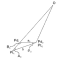
次に、路面推定部24によって行われる路面の傾きを推定する方法について、図4を参照しながら説明する。図4は、図1の路面推定部24によって行われる路面の傾きの推定方法を示す説明図である。なお、ここでは、変数をnとしており、0≦n≦k−2を満たす。
Next, a method for estimating the slope of the road surface performed by the road
図4において、位置変換部23による変換計算上の路面に存在する各規則物体の検出位置Pd0〜Pd3と、実際の路面に存在する各規則物体の実際の位置Pt0〜Pt3との位置関係が示されている。実位置Pt0〜Pt3は、カメラ1のレンズ中心Oと検出位置Pd0〜Pd3とを通る各直線に存在し、既知である設置間隔bで実位置Pt0〜Pt3が直線状に並んでいるものとしている。
In FIG. 4, detection positions Pd 0 to Pd 3 of each regular object existing on the road surface in the conversion calculation by the
レンズ中心Oの変換計算上の路面からの高さH0は、カメラ設置情報に含まれていることから、既知である。また、レンズ中心Oと検出位置Pd0〜Pd3とを通る各直線と、変換計算上の路面とがなす角は、レンズ中心Oと検出位置Pd0〜Pd3との位置関係から、求めることができる。 The height H 0 from the road surface in the conversion calculation of the lens center O is known because it is included in the camera installation information. Further, the angle formed between each straight line passing through the lens center O and the detection positions Pd 0 to Pd 3 and the road surface in the conversion calculation is obtained from the positional relationship between the lens center O and the detection positions Pd 0 to Pd 3. Can do.
上記の推定方法では、実位置PtnとPtn+1の間が直線であると近似し、変換計算上の路面と、直線PtnPtn+1のなす角度θnが路面の傾きθnとして算出される。 In the above estimation method, it is approximated that the distance between the actual positions Pt n and Pt n + 1 is a straight line, and the angle θ n formed by the road surface in the conversion calculation and the straight line Pt n Pt n + 1 is calculated as the road surface inclination θ n. .
続いて、路面の傾きθ0を計算する方法について、図5および図6を参照しながら説明する。図5は、図1の路面推定部24が路面の傾きθ0を計算する第1の計算方法を示す説明図である。図6は、図1の路面推定部24が路面の傾きθ0を計算する第2の計算方法を示す説明図である。
Next, a method of calculating the road surface inclination θ 0 will be described with reference to FIGS. 5 and 6. FIG. 5 is an explanatory diagram showing a first calculation method in which the road
なお、路面の傾きθ0を計算する前提として、検出位置Pd0がレンズ中心Oからの距離が最も短い検出位置である。そこで、検出位置Pd0と実位置Pt0とがほぼ等しいと考え、図5および図6に示すように、Pd0=Pt0であるものとしている。 As a premise for calculating the road surface inclination θ 0 , the detection position Pd 0 is the detection position with the shortest distance from the lens center O. Therefore, it is assumed that the detection position Pd 0 and the actual position Pt 0 are substantially equal, and it is assumed that Pd 0 = Pt 0 as shown in FIGS.
図5では、a0<b、すなわち、変換計算上の路面に対して、実際の路面が下方向に傾斜している場合の路面の傾きθ0を計算する第1の計算方法を示している。また、図5では、三角形Pt0Pt1Pd1において、∠Pd1Pt0Pt1、すなわち直線Pt0Pt1と直線Pd0Pd1とがなす角度をθ0とし、∠Pt0Pt1Pd1をA0とし、∠Pt0Pd1Pt1をB0としている。 FIG. 5 shows a first calculation method for calculating the slope θ 0 of the road surface when a 0 <b, that is, the actual road surface is inclined downward with respect to the road surface in the conversion calculation. . In FIG. 5, in the triangle Pt 0 Pt 1 Pd 1 , ∠Pd 1 Pt 0 Pt 1 , that is, the angle formed by the straight line Pt 0 Pt 1 and the straight line Pd 0 Pd 1 is θ 0, and ∠Pt 0 Pt 1 Pd 1 is A 0 and ∠Pt 0 Pd 1 Pt 1 is B 0 .
三角形Pt0Pt1Pd1において、正弦定理より以下の式(1)が成立し、式(1)を変形すると、以下の式(2)のようになる。また、三角形Pt0Pt1Pd1において、以下の式(3)が成立する。
b/sinB0=a0/sinA0 (1)
sinA0=a0sinB0/b (2)
θ0=π−(A0+B0) (3)
In the triangle Pt 0 Pt 1 Pd 1 , the following formula (1) is established from the sine theorem, and when the formula (1) is transformed, the following formula (2) is obtained. Further, in the triangle Pt 0 Pt 1 Pd 1 , the following expression (3) is established.
b / sinB 0 = a 0 / sinA 0 (1)
sinA 0 = a 0 sinB 0 / b (2)
θ 0 = π− (A 0 + B 0 ) (3)
このとき、a0およびbの各値は既知である。また、∠OPd1Pd0、すなわち、レンズ中心Oから検出位置Pd1を結んだ直線と変換計算上の路面とがなす角が既知であるので、B0の値が決まる。さらに、0<A0<π/2を満たす。以上から、式(2)より、A0の値が一意に決まる。このように、A0の値が決まれば、式(3)より、θ0の値が決まる。 In this case, the values of a 0 and b are known. Further, since the angle between ∠OPd 1 Pd 0 , that is, the straight line connecting the detection position Pd 1 from the lens center O and the road surface in the conversion calculation is known, the value of B 0 is determined. Further, 0 <A 0 <π / 2 is satisfied. From the above, the value of A 0 is uniquely determined from Equation (2). Thus, if the value of A 0 is determined, the value of θ 0 is determined from Equation (3).
図6では、a0>b、すなわち、変換計算上の路面に対して、実際の路面が上方向に傾斜している場合の路面の傾きθ0を計算する第2の計算方法を示している。 FIG. 6 shows a second calculation method for calculating the slope θ 0 of the road surface when a 0 > b, that is, the actual road surface is inclined upward with respect to the road surface in the conversion calculation. .
図6においても、図5と同様に、式(1)〜式(3)を満たし、B0の値が決まり、さらに、π/2<A0<πを満たす。したがって、上記と同様に、式(2)より、A0の値が一意に決まり、その結果、式(3)より、θ0の値が決まる。 Also in FIG. 6, as in FIG. 5, Expressions (1) to (3) are satisfied, the value of B 0 is determined, and π / 2 <A 0 <π is satisfied. Therefore, similarly to the above, the value of A 0 is uniquely determined from the equation (2), and as a result, the value of θ 0 is determined from the equation (3).
続いて、路面の傾きθnを計算する方法(ただし、n≧1)について、図7を参照しながら説明する。図7は、図1の路面推定部24が路面の傾きθnを計算する方法(ただし、n≧1)を示す説明図である。
Next, a method for calculating the road surface inclination θ n (where n ≧ 1) will be described with reference to FIG. FIG. 7 is an explanatory diagram showing how the road
図7では、実位置Ptnから、直線PdnPdn+1と平行な直線を引き、その直線と直線OPtn+1との交点をPd’n+1とし、直線PtnPd’n+1の長さをa’nとしている。三角形PtnPtn+1Pd’n+1において、∠Pd’n+1PtnPtn+1、すなわち直線PtnPtn+1と直線PtnPd’n+1とがなす角度を、路面の傾きθnとしている。また、∠Pd’n+1Ptn+1PtnをAnとし、∠Ptn+1Pd’n+1PtnをBnとしている。三角形OPdnPdn+1の高さをH0とし、三角形OPd’n+1Ptnの高さをH0+hnとしている。 In FIG. 7, a straight line parallel to the straight line Pd n Pd n + 1 is drawn from the actual position Pt n , the intersection of the straight line and the straight line OPt n + 1 is Pd ′ n + 1, and the length of the straight line Pt n Pd ′ n + 1 is a ′ n It is said. In the triangle Pt n Pt n + 1 Pd ′ n + 1 , ∠Pd ′ n + 1 Pt n Pt n + 1 , that is, an angle formed by the straight line Pt n Pt n + 1 and the straight line Pt n Pd ′ n + 1 is defined as a road surface inclination θ n . Further, ∠Pd 'a n + 1 Pt n + 1 Pt n and A n, ∠Pt n + 1 Pd ' has a n + 1 Pt n and B n. The height of the triangle OPd n Pd n + 1 is H 0, and the height of the triangle OPd ′ n + 1 Pt n is H 0 + h n .
ここで、hnとhn−1の関係について以下の式(4)を満たし、anとa’nの関係について以下の式(5)を満たす。
hn=hn−1+bsinθn−1 (4)
a’n:an=(H0+hn):H0 (5)
Here, satisfies Expression (4) below the relationship between h n and h n-1, satisfy equation (5) below the relationship between a n and a 'n.
h n = h n-1 + bsin θ n-1 (4)
a ′ n : a n = (H 0 + h n ): H 0 (5)
また、式(4)および式(5)から、以下の式(6)を導出することができる。
a’n=an(H0+hn−1+bsinθn−1)/H0 (6)
Further, the following equation (6) can be derived from the equations (4) and (5).
a ′ n = a n (H 0 + h n−1 + b sin θ n−1 ) / H 0 (6)
三角形PtnPtn+1Pd’n+1において、式(6)よりa’nの値が決まり、bの値は既知である。また、∠OPdn+1Pdn、すなわち、レンズ中心Oから検出位置Pdn+1を結んだ直線と変換計算上の路面とがなす角が既知であるので、Bnの値が決まる。したがって、図5および図6に示す計算方法と同様に計算することで、θnの値が決まる。 In the triangle Pt n Pt n + 1 Pd ′ n + 1 , the value of a ′ n is determined from the equation (6), and the value of b is known. Further, since the angle formed by ∠OPd n + 1 Pd n , that is, the straight line connecting the detection position Pd n + 1 from the lens center O and the road surface in the conversion calculation is known, the value of B n is determined. Therefore, by calculating similarly to the calculation method shown in FIGS. 5 and 6, the value of theta n is determined.
このように、路面推定部24は、図5〜図7に示す計算方法によって、路面の傾きθ0〜θnを計算することができる。
As described above, the road
以上、本実施の形態1によれば、カメラから取得した車両周辺画像から規則物体を検出し、各規則物体の画像上での位置を、カメラ設置情報を用いて画像上から実空間上へ変換することで各規則物体の検出位置を計算するように構成されている。また、各検出位置において隣り合う検出位置の検出間隔をそれぞれ計算し、各検出位置と、計算した各検出間隔と、規則物体の設置間隔とから、画像上から実空間上への変換計算上の路面に対する実際の路面の傾きを推定するように構成されている。 As described above, according to the first embodiment, the regular objects are detected from the vehicle peripheral image acquired from the camera, and the position of each regular object on the image is converted from the image to the real space using the camera installation information. By doing so, the detection position of each regular object is calculated. In addition, the detection interval between adjacent detection positions at each detection position is calculated, and the conversion calculation from the image to the real space is calculated from each detection position, each calculated detection interval, and the installation interval of the regular object. The actual road surface inclination with respect to the road surface is estimated.
これにより、カメラ以外のセンサを用いることなく、車両周辺の路面の起伏をカメラによって撮像された画像から計算することが可能となるので、その結果、車両が走行する路面の起伏を推定することができる。 This makes it possible to calculate the undulation of the road surface around the vehicle from the image captured by the camera without using a sensor other than the camera, and as a result, the undulation of the road surface on which the vehicle travels can be estimated. it can.
また、本実施の形態1では、既知である設置間隔で設置されている規則物体を利用し、その設置間隔を用いて路面の傾きを推定するように構成されているので、後述する実施の形態2、3のようにその設置間隔を計算する場合と比べて、路面起伏の算出に要する処理負荷を低減することができる。 In the first embodiment, a regular object that is installed at a known installation interval is used, and the road surface inclination is estimated using the installation interval. Compared with the case where the installation interval is calculated as in 2 and 3, the processing load required for calculating the road surface undulation can be reduced.
実施の形態2.
本発明の実施の形態2では、先の実施の形態1の構成に対して、距離を示す数値が表示されている規則物体を利用して、規則物体の設置間隔を計算するように構成されている路面起伏推定装置2について説明する。なお、本実施の形態2では、先の実施の形態1と同様である点の説明を省略し、先の実施の形態1と異なる点を中心に説明する。
The second embodiment of the present invention is configured to calculate the installation interval of the regular object using the regular object on which the numerical value indicating the distance is displayed, compared to the configuration of the first embodiment. The existing road surface
ここで、先の実施の形態1では、設置間隔が法令等によって規定されている規則物体を対象としているので、規則物体の設置間隔が既知である。これに対して、本実施の形態2では、距離を示す数値が表示されている規則物体を対象とするとともに、その規則物体に表示されている数値を利用して規則物体の設置間隔を計算するように構成されている。 Here, in the first embodiment, since a regular object whose installation interval is prescribed by law or the like is targeted, the installation interval of the regular object is known. On the other hand, in the second embodiment, the regular object on which the numerical value indicating the distance is displayed is targeted, and the installation interval of the regular object is calculated using the numerical value displayed on the regular object. It is configured as follows.
距離を示す数値が表示されている規則物体として、例えば、車両とその前方を走行する他車両との距離を運転手が把握する目的で等間隔に設置されている車間距離表示板、および高速道路に設置されている起点の地点から現在地の距離を示す表示板等が挙げられる。 As the regular objects on which the numerical values indicating the distance are displayed, for example, an inter-vehicle distance display board installed at equal intervals for the purpose of allowing the driver to grasp the distance between the vehicle and another vehicle traveling in front of the vehicle, and an expressway And a display board showing the distance from the starting point to the current location.
図8は、本発明の実施の形態2における路面起伏推定装置2を示す構成図である。図8において、路面起伏推定装置2は、記憶部21、対象物検出部22、位置変換部23、路面推定部24および設置間隔取得部25を備える。
FIG. 8 is a configuration diagram showing the road surface
設置間隔取得部25は、カメラ1から入力された車両周辺画像の規則物体に表示されている数値を認識することで、規則物体の設置間隔を計算する。設置間隔取得部25は、計算して取得した設置間隔を路面推定部24に出力する。路面推定部24は、先の実施の形態1とは異なり、設置間隔取得部25から入力された設置間隔を用いて、路面の傾きを推定する。
The installation
次に、本実施の形態2における路面起伏推定装置2の一連の動作について、図9および図10を参照しながら説明する。図9は、図8の路面起伏推定装置2の一連の動作を示すフローチャートである。図10は、図8の対象物検出部22が車両周辺画像から各規則物体を検出する動作の一例を示す説明図である。
Next, a series of operations of the road surface
なお、図9のフローチャートの処理は、例えばあらかじめ設定された処理周期で繰り返し実行される。また、ここでは、規則物体が車間距離表示板4であるものとする。この場合、対象物検出部22は、各車間距離表示板4と路面とが接する位置を、各車間距離表示板4の画像上での位置として検出するように設定される。
Note that the processing of the flowchart of FIG. 9 is repeatedly executed at, for example, a preset processing cycle. Here, it is assumed that the regular object is the inter-vehicle distance display plate 4. In this case, the
図9に示すように、ステップS201において、対象物検出部22および設置間隔取得部25は、カメラ1から車両周辺画像を取得し、処理がステップS202へと進む。
As shown in FIG. 9, in step S201, the
対象物検出部22は、先の図2のステップS102,S103と同様の処理であるステップS202,S203を実行する。
The
ステップS204において、設置間隔取得部25は、カメラ1から取得した車両周辺画像から、規則物体に表示されている数値を認識することで、規則物体の設置間隔bを計算し、処理がステップS205へと進む。
In step S204, the installation
対象物検出部22は、先のステップS105と同様の処理であるステップS205を実行し、処理がステップS206へと進む。
The
位置変換部23は、先の図2のステップS106と同様の処理であるステップS206を実行し、処理がステップS207へと進む。
The
ステップS207において、路面推定部24は、位置変換部23から入力された各規則物体の検出位置Pd0,Pd1,・・・,Pdk−1から、各規則物体の検出間隔a0,a1,・・・,ak−2を計算する。続いて、路面推定部24は、位置変換部23から入力された各規則物体の検出位置Pd0,Pd1,・・・,Pdk−1と、計算した各規則物体の検出間隔a0,a1,・・・,ak−2と、設置間隔取得部25から取得した設置間隔bとから、路面の傾きθ0,θ1,・・・,θk−2を推定し、一連の処理が終了となる。路面推定部24は、先の実施の形態1で説明した計算方法、すなわち、先の図5〜図7に示す計算方法によって、路面の傾きθ0〜θk−2を計算する。
In step S207, the road
ここで、カメラ1から取得した車両周辺画像が図10に示す状況である場合を考える。この場合、k=3であり、ステップS204において、設置間隔取得部25は、カメラ1から取得した車両周辺画像から、各車間距離表示板4に表示されている数値、すなわち、0m,50m,100mを認識することで、設置間隔bを計算し、その値を50mとする。ステップS205において、対象物検出部22は、各車間距離表示板4の画像上での位置Pi0〜Pi2を取得する。
Here, consider a case where the vehicle periphery image acquired from the camera 1 is in the situation shown in FIG. In this case, k = 3, and in step S204, the installation
ステップS206において、位置変換部23は、各車間距離表示板4の画像上での位置Pi0〜Pi2を、各車間距離表示板4の検出位置Pd0〜Pd2に変換する。ステップS207において、路面推定部24は、各車間距離表示板4の検出位置Pd0〜Pd2と、各車間距離表示板4の検出間隔a0,a1と、設置間隔b(=50m)とから、路面の傾きθ0,θ1を推定する。
In step S206, the
以上、本実施の形態2によれば、距離を示す数値を表示する規則物体を利用し、カメラから取得した車両周辺画像から規則物体を検出し、検出した各規則物体に表示されている数値を認識することで、設置間隔を計算し、その設置間隔を用いて路面の傾きを推定するように構成されている。 As described above, according to the second embodiment, the regular object that displays the numerical value indicating the distance is used, the regular object is detected from the vehicle peripheral image acquired from the camera, and the numerical value displayed on each detected regular object is determined. By recognizing, the installation interval is calculated, and the inclination of the road surface is estimated using the installation interval.
これにより、先の実施の形態1と同様の効果が得られるとともに、先の実施の形態1のように設置間隔が既知でなくても、路面の起伏を推定することができる。 As a result, the same effect as in the first embodiment can be obtained, and the road surface undulation can be estimated even if the installation interval is not known as in the first embodiment.
実施の形態3.
本発明の実施の形態3では、先の実施の形態1の構成に対して、設置間隔が未知であって、繰り返し出現する特徴を持つ規則物体を利用して、規則物体の設置間隔を計算するように構成されている路面起伏推定装置2について説明する。なお、本実施の形態3では、先の実施の形態1、2と同様である点の説明を省略し、先の実施の形態1、2と異なる点を中心に説明する。
Embodiment 3 FIG.
In Embodiment 3 of the present invention, with respect to the configuration of Embodiment 1 above, the installation interval of the regular object is calculated using a regular object whose installation interval is unknown and has repetitive features. The road surface
ここで、先の実施の形態2では、距離を示す数値が表示されている規則物体を対象とし、その数値から規則物体の設置間隔を計算するように構成されている。これに対して、本実施の形態3では、設置間隔が未知であって、繰り返し出現する特徴を持つ規則物体を対象とし、その特徴を利用して規則物体の設置間隔を計算するように構成されている。 Here, in the second embodiment, the regular object on which the numerical value indicating the distance is displayed is the target, and the installation interval of the regular object is calculated from the numerical value. On the other hand, the third embodiment is configured to calculate a regular object installation interval by using a regular object having a feature that has an unknown installation interval and repeatedly appearing characteristics. ing.
設置間隔が未知であって、繰り返し出現する特徴を持つ規則物体として、例えば、ガードレールの支柱、防風壁の支柱および防砂壁の支柱等が挙げられる。 Examples of the regular object whose installation interval is unknown and that repeatedly appears include a guard rail column, a wind barrier column, and a sand barrier column.
図11は、本発明の実施の形態3における路面起伏推定装置2を示す構成図である。図11において、路面起伏推定装置2は、記憶部21、対象物検出部22、位置変換部23、路面推定部24および設置間隔推定部26を備える。また、路面起伏推定装置2には、車両情報取得部5から運動情報が入力される。
FIG. 11 is a configuration diagram showing a road surface
車両情報取得部5は、車速およびヨーレート等の車両の運動情報を取得し、取得した運動情報を設置間隔推定部26に出力する。車両情報取得部5は、例えば、車速センサおよびヨーレートセンサ等を用いて構成される。
The vehicle information acquisition unit 5 acquires vehicle motion information such as vehicle speed and yaw rate, and outputs the acquired motion information to the installation
対象物検出部22は、カメラ1から取得した車両周辺画像から繰り返し出現する特徴を持つ規則物体を抽出し、車両周辺画像の経時的な変化から、基準位置に規則物体が現れた時の出現時刻を順番に取得し、それらの出現時刻を設置間隔推定部26に出力する。
The
設置間隔推定部26は、車両情報取得部5から運動情報を取得する。また、設置間隔推定部26は、対象物検出部22から入力された各出現時刻と、その各出現時刻に対応する運動情報とを用いて、規則物体の間隔を計算する。設置間隔推定部26は、計算して推定した設置間隔を路面推定部24に出力する。路面推定部24は、先の実施の形態1とは異なり、設置間隔推定部26から入力された設置間隔を用いて、路面の傾きを推定する。
The installation
次に、本実施の形態3における路面起伏推定装置2の一連の動作について、図12〜図14を参照しながら説明する。図12は、図11の路面起伏推定装置2の一連の動作を示すフローチャートである。図13は、図11の対象物検出部22が車両周辺画像の経時的な変化から、基準位置Prに規則物体が現れた時の出現時刻を順番に取得する方法を示す説明図である。図14は、図11の対象物検出部22が車両周辺画像から各規則物体を検出する動作の一例を示す説明図である。
Next, a series of operations of the road surface
なお、図12のフローチャートの処理は、例えばあらかじめ設定された処理周期で繰り返し実行される。また、ここでは、規則物体がガイドレールの支柱6であるものとする。この場合、対象物検出部22は、支柱6と路面が接する位置を、各支柱6の画像上での位置として検出するように設定される。
Note that the processing of the flowchart of FIG. 12 is repeatedly executed at, for example, a preset processing cycle. Here, it is assumed that the regular object is a
図12に示すように、対象物検出部22は、先の図2のステップS101〜S103と同様の処理であるステップS301〜S303を実行する。
As shown in FIG. 12, the
ステップS304において、対象物検出部22は、カメラ1から取得した車両周辺画像の経時的な変化から、あらかじめ設定されている基準位置に規則物体が現れた時の出現時刻を順番に取得する。
In step S <b> 304, the
例えば、カメラ1から取得した車両周辺画像の経時変化が図13に示す状況である場合を考える。なお、図13では、分かりやすくするために、2つの支柱6に対して、基準位置Prから近い順番に、6_1,6_2を付している。
For example, consider a case where the time-dependent change of the vehicle periphery image acquired from the camera 1 is the situation shown in FIG. In FIG. 13, 6_1 and 6_2 are attached to the two
図13において、対象物検出部22は、カメラ1から取得した車両周辺画像の経時的な変化から、基準位置Prに支柱6がはじめて現れた時、すなわち、基準位置Prに1番目の支柱6_1が現れた時の出現時刻t0を取得する。また、対象物検出部22は、取得した出現時刻t0を設置間隔推定部26に出力する。
In FIG. 13, the
続いて、対象物検出部22は、カメラ1から取得した車両周辺画像の経時的な変化から、基準位置Prに2番目の支柱6_2が現れた時の出現時刻t1を取得する。また、対象物検出部22は、取得した出現時刻t1を設置間隔推定部26に出力する。
Then, the
このように、対象物検出部22は、カメラ1から取得した車両周辺画像の経時的な変化から、基準位置に規則物体が現れた時の出現時刻を順番に取得する。なお、対象物検出部22によって取得された出現時刻の数をjとするとき、j≧2を満たすようにあらかじめ設定しておけばよい。
As described above, the
図12の説明に戻り、ステップS305において、設置間隔推定部26は、対象物検出部22から入力された各出現時刻と、その各出現時刻に対応する運動情報とから、規則物体の設置間隔bを計算する。
Returning to the description of FIG. 12, in step S305, the installation
具体的には、設置間隔推定部26は、各出現時刻t0,t1,・・・,tj−1において、時系列で隣り合う出現時刻の時間間隔Δt1(=t1−t0),・・・,Δtj(=tj−1−tj−2)をそれぞれ計算する。設置間隔推定部26は、対象物検出部22から入力された各出現時刻t0〜tj−1に対応する運動情報から、各時間間隔Δt1〜Δtjにおいて車両が移動した距離を、それぞれ計算する。続いて、設置間隔推定部26は、計算した各時間間隔Δt1〜Δtjに対応する距離から設置間隔bを計算する。例えば、計算した各時間間隔Δt1〜Δtjに対応する距離の平均値を設置間隔bとすればよい。
Specifically, the installation
対象物検出部22は、先の図2のステップS105と同様の処理であるステップS306を実行し、処理がステップS307へと進む。
The
位置変換部23は、先の図2のステップS106と同様の処理であるステップS307を実行し、処理がステップS308へと進む。
The
ステップS308において、路面推定部24は、位置変換部23から入力された各規則物体の検出位置Pd0,Pd1,・・・,Pdk−1から、各規則物体の検出間隔a0,a1,・・・,ak−2を計算する。続いて、路面推定部24は、位置変換部23から入力された各規則物体の検出位置Pd0,Pd1,・・・,Pdk−1と、計算した各規則物体の検出間隔a0,a1,・・・,ak−2と、設置間隔推定部26から取得した設置間隔bとから、路面の傾きθ0,θ1,・・・,θk−2を推定し、一連の処理が終了となる。路面推定部24は、先の実施の形態1で説明した計算方法、すなわち、先の図5〜図7に示す計算方法によって、路面の傾きθ0〜θk−2を計算する。
In step S308, the road
ここで、カメラ1から取得した車両周辺画像が図14に示す状況である場合を考える。この場合、k=9であり、ステップS306において、対象物検出部22は、各支柱6の画像上での位置Pi0〜Pi8を取得する。
Here, consider a case where the vehicle periphery image acquired from the camera 1 is in the situation shown in FIG. In this case, k = 9, and in step S306, the
ステップS307において、位置変換部23は、各支柱6の画像上での位置Pi0〜Pi8を、各支柱6の検出位置Pd0〜Pd8に変換する。ステップS308において、路面推定部24は、各支柱6の検出位置Pd0〜Pd8と、各支柱6の検出間隔a0〜a7と、設置間隔推定部26から取得した設置間隔bとから、路面の傾きθ0〜θ7を推定する。
In step S307, the
以上、本実施の形態3によれば、設置間隔が未知であって、繰り返し出現する特徴を持つ規則物体を利用し、カメラから取得した車両周辺画像の経時的な変化から、画像上の基準位置に規則物体が現れた時の出現時刻を順に取得し、各出現時刻と、各出現時刻に対応する運動情報とから、設置間隔を計算するように構成されている。 As described above, according to the third embodiment, the reference position on the image is obtained from the temporal change of the vehicle peripheral image obtained from the camera using the regular object having the feature where the installation interval is unknown and repeatedly appears. Appearance times when regular objects appear are sequentially acquired, and an installation interval is calculated from each appearance time and motion information corresponding to each appearance time.
これにより、先の実施の形態1と同様の効果が得られるとともに、先の実施の形態1のように設置間隔が既知でなくても、路面の起伏を推定することができる。 As a result, the same effect as in the first embodiment can be obtained, and the road surface undulation can be estimated even if the installation interval is not known as in the first embodiment.
なお、本実施の形態1〜3について個別に説明してきたが、本実施の形態1〜3のそれぞれで開示した構成例は、任意に組み合わせることが可能である。また、規則物体の設置間隔を求める方法として、先の実施の形態1〜3のそれぞれで説明してきたが、これらの方法に限定されず、車両周辺画像を用いて検出間隔を求める方法以外の方法であれば、どのような方法で求めてもよい。 In addition, although this Embodiment 1-3 was demonstrated separately, the structural example disclosed by each of this Embodiment 1-3 can be combined arbitrarily. Further, the method for obtaining the installation interval of the regular object has been described in each of the first to third embodiments. However, the method is not limited to these methods, and a method other than the method for obtaining the detection interval using the vehicle peripheral image. Any method may be used as long as it is.
なお、実環境において路面が起伏していることに起因して生じうるカメラによる対象物検知の測距性能の低下に対して、本願発明を適用することで路面の起伏が常に一定とは限らない車両走行時における路面の起伏を推定してその推定結果を用いて測距を行うように構成すれば、そのような性能の低下の改善を期待することができる。 It should be noted that the undulation of the road surface is not always constant by applying the present invention against the degradation of the ranging performance of the object detection by the camera that may occur due to the undulation of the road surface in the actual environment. If the undulation of the road surface during vehicle travel is estimated and distance measurement is performed using the estimation result, such a decrease in performance can be expected.
また、本願発明によって、車両が走行する車線の起伏をあらかじめ検出することが可能となるので、アクティブサスペンションの制御技術への本願発明の適用を期待することができる。さらに、本願発明によって、高速道路における自然渋滞の発生要因となるサグ(凹部)を事前に検出することができるので、ドライバに速度注意の喚起等を行う技術への本願発明の適用を期待することができる。 Further, according to the present invention, it is possible to detect in advance the undulation of the lane in which the vehicle travels, so that the application of the present invention to the control technology of the active suspension can be expected. Furthermore, since the present invention can detect in advance a sag (concave portion) that is a cause of natural traffic jams on a highway, the application of the present invention to a technique for alerting the driver of speed, etc. is expected. Can do.
1 カメラ、2 路面起伏推定装置、21 記憶部、22 対象物検出部、23 位置変換部、24 路面推定部、25 設置間隔取得部、26 設置間隔推定部、3 破線区画線の線部、4 車間距離表示板、5 車両情報取得部、6 ガイドレールの支柱。 DESCRIPTION OF SYMBOLS 1 Camera, 2 Road surface undulation estimation apparatus, 21 Memory | storage part, 22 Object detection part, 23 Position conversion part, 24 Road surface estimation part, 25 Installation space | interval acquisition part, 26 Installation space | interval estimation part, 3 Line part of a broken line Inter-vehicle distance display board, 5 vehicle information acquisition unit, 6 guide rail support.
Claims (6)
事前に求められたカメラ設置情報を記憶する記憶部と、
前記カメラから取得した前記車両周辺画像から、前記路面に一定の設置間隔で設置されている規則物体を検出し、検出した各規則物体の画像上での位置を計算し、計算結果を位置情報として出力する対象物検出部と、
前記対象物検出部から入力された前記位置情報と、前記記憶部から取得した前記カメラ設置情報とから、各規則物体の画像上での位置を、各規則物体の実空間での位置に変換し、変換結果を各規則物体の検出位置として出力する位置変換部と、
前記位置変換部から入力された各検出位置において隣り合う検出位置の検出間隔をそれぞれ計算し、前記カメラのレンズ中心と各検出位置との位置関係から、前記レンズ中心と各検出位置とを通る各直線と、前記位置変換部による変換計算上の路面とがなす角をそれぞれ求め、前記位置変換部による変換計算上の路面に対する実際の路面の傾きを推定する路面推定部と、
を備え、
前記レンズ中心の位置をOとし、
前記実際の路面に存在する各規則物体の実際の位置について、前記レンズ中心に最も近い位置をPt 0 とし、Pt 0 から近い順にPt 1 ,・・・Pt n+1 (ただし、nは1以上の整数)とし、
各検出位置について、前記レンズ中心に最も近い位置をPd 0 とし、Pd 0 とPt 0 が一致していると仮定し、Pd 0 から近い順にPd 1 ,・・・Pd n+1 とし、
各検出間隔について、隣り合うPd 0 ,Pd 1 の検出間隔をa 0 とし、a 0 から近い順にa 1 ,・・・,a n とし、
前記規則物体の前記設置間隔をbとし、
前記レンズ中心と各検出位置とを通る各直線と、前記位置変換部による変換計算上の路面とがなす角について、∠OPd 1 Pd 0 ,∠OPd 2 Pd 1 ,・・・,∠OPd n+1 Pd n とし、
前記レンズ中心の前記変換計算上の路面からの高さをH 0 とし、
前記変換計算上の路面と、各直線Pt 0 Pt 1 ,・・・,Pt n Pt n+1 とがなす角について、θ 0 ,・・・,θ n としたとき、
前記路面推定部は、
∠OPd 1 Pd 0 と、a 0 と、bとから、θ 0 を前記実際の路面の傾きとして推定し、
∠OPd 2 Pd 1 ,・・・,∠OPd n+1 Pd n と、a 1 ,・・・,a n と、bと、H 0 と、θ 0 とから、θ 1 ,・・・,θ n を、前記実際の路面の傾きとして推定する
路面起伏推定装置。 A road surface undulation estimation device to which a vehicle periphery image captured by a camera mounted on the vehicle is input so that the periphery of the vehicle traveling on the road surface can be imaged,
A storage unit for storing camera setting information obtained in advance;
From the vehicle periphery image acquired from the camera, a regular object installed on the road surface at a fixed installation interval is detected, the position of each detected regular object on the image is calculated, and the calculation result is used as position information. An object detection unit to output;
From the position information input from the target object detection unit and the camera installation information acquired from the storage unit, the position of each regular object on the image is converted into the position of each regular object in real space. A position conversion unit that outputs a conversion result as a detection position of each regular object;
The detection intervals of the detection positions adjacent to each other at each detection position input from the position conversion unit are calculated, and each passing through the lens center and each detection position from the positional relationship between the lens center and each detection position of the camera. the straight line and the position respectively determined road surface and the angle of the transform computation by the conversion unit, the actual road surface estimating section for estimating a gradient of a road surface with respect to the road surface on the conversion calculation by pre Symbol position conversion unit,
Equipped with a,
The position of the lens center is O,
With respect to the actual position of each regular object existing on the actual road surface, the position closest to the lens center is Pt 0, and Pt 1 ,... Pt n + 1 (where n is an integer equal to or greater than 1) in order from Pt 0 )age,
For each detection position, let Pd 0 be the position closest to the lens center, and assume that Pd 0 and Pt 0 match, and Pd 1 ,... Pd n + 1 in order from Pd 0 ,
For each detection interval, the detection interval of Pd 0, Pd 1 adjacent to the a 0, a 1, · · ·, and a n in order of proximity to the a 0,
The installation interval of the regular objects is b,
角 OPd 1 Pd 0 , ∠OPd 2 Pd 1 ,..., ∠OPd n + 1 Pd with respect to the angle formed between each straight line passing through the lens center and each detection position and the road surface on the conversion calculation by the position conversion unit. n ,
The height of the lens center from the road surface in the conversion calculation is H 0 .
And the road surface on the transform computation, the linear Pt 0 Pt 1, · · ·, for angle between Pt n Pt n + 1, θ 0, ···, when the theta n,
The road surface estimation unit is
From θOPd 1 Pd 0 , a 0 , and b, θ 0 is estimated as the actual road slope,
∠OPd 2 Pd 1, ···, and ∠OPd n + 1 Pd n, a 1, ···, and a n, and b, or H 0, the theta 0 Prefecture, θ 1, ···, a theta n A road surface undulation estimation device that estimates the inclination of the actual road surface .
前記記憶部は、前記設置間隔をさらに記憶し、
前記路面推定部には、前記記憶部に記憶されている前記設置間隔が入力される
請求項1に記載の路面起伏推定装置。 The regular objects are installed at the installation intervals that are known;
The storage unit further stores the installation interval,
The road surface undulation estimation apparatus according to claim 1, wherein the installation interval stored in the storage unit is input to the road surface estimation unit.
前記カメラから取得した前記車両周辺画像から前記規則物体を検出し、検出した各規則物体に表示されている前記数値を認識することで、前記設置間隔を計算する設置間隔取得部をさらに備え、
前記路面推定部には、前記設置間隔取得部によって計算された前記設置間隔が入力される
請求項1に記載の路面起伏推定装置。 The regular object displays a numerical value indicating a distance,
Further comprising an installation interval acquisition unit that detects the regular object from the vehicle peripheral image acquired from the camera and recognizes the numerical value displayed on each detected regular object to calculate the installation interval;
The road surface undulation estimation apparatus according to claim 1, wherein the installation interval calculated by the installation interval acquisition unit is input to the road surface estimation unit.
前記対象物検出部は、前記カメラから取得した前記車両周辺画像の経時的な変化から、画像上の基準位置に前記規則物体が現れた時の出現時刻を順に取得し、取得結果をさらに出力し、
前記車両の速度情報を取得する車両情報取得部から前記速度情報を取得し、前記対象物検出部から入力された各出現時刻と、各出現時刻に対応する前記速度情報とから、前記設置間隔を計算する設置間隔推定部をさらに備え、
前記路面推定部には、前記設置間隔推定部によって計算された前記設置間隔が入力される
請求項1に記載の路面起伏推定装置。 The regular object has a feature that the installation interval is unknown and repeatedly appears,
The object detection unit sequentially acquires appearance times when the regular object appears at a reference position on the image from a temporal change in the vehicle periphery image acquired from the camera, and further outputs an acquisition result. ,
It acquires the speed information from the vehicle information acquisition unit that acquires speed information of the vehicle, and the appearance time input from the object detecting unit from said velocity information corresponding to each occurrence time, the installation interval It further includes an installation interval estimation unit for calculating,
The road surface undulation estimation apparatus according to claim 1, wherein the installation interval calculated by the installation interval estimation unit is input to the road surface estimation unit.
請求項4に記載の路面起伏推定装置。 The installation interval estimation unit calculates a time interval between appearance times adjacent in time series at each appearance time input from the object detection unit, and calculates each time calculated from the speed information corresponding to each appearance time. The road surface undulation estimation apparatus according to claim 4, wherein the distance traveled by the vehicle in the interval is calculated, and the installation interval is calculated from the distance corresponding to each calculated time interval.
前記カメラから取得した前記車両周辺画像から、前記路面に一定の設置間隔で設置されている規則物体を検出し、検出した各規則物体の画像上での位置を計算し、計算結果を位置情報として出力する対象物検出ステップと、
前記対象物検出ステップで出力された前記位置情報と、事前に求められたカメラ設置情報とから、各規則物体の画像上での位置を、各規則物体の実空間での位置に変換し、変換結果を各規則物体の検出位置として出力する位置変換ステップと、
前記位置変換ステップで出力された各検出位置において隣り合う検出位置の検出間隔をそれぞれ計算し、前記カメラのレンズ中心と各検出位置との位置関係から、前記レンズ中心と各検出位置とを通る各直線と、前記位置変換ステップでの変換計算上の路面とがなす角をそれぞれ求め、前記位置変換ステップでの変換計算上の路面に対する実際の路面の傾きを推定する路面推定ステップと、
を備え、
前記レンズ中心の位置をOとし、
前記実際の路面に存在する各規則物体の実際の位置について、前記レンズ中心に最も近い位置をPt 0 とし、Pt 0 から近い順にPt 1 ,・・・Pt n+1 (ただし、nは1以上の整数)とし、
各検出位置について、前記レンズ中心に最も近い位置をPd 0 とし、Pd 0 とPt 0 が一致していると仮定し、Pd 0 から近い順にPd 1 ,・・・Pd n+1 とし、
各検出間隔について、隣り合うPd 0 ,Pd 1 の検出間隔をa 0 とし、a 0 から近い順にa 1 ,・・・,a n とし、
前記規則物体の前記設置間隔をbとし、
前記レンズ中心と各検出位置とを通る各直線と、前記位置変換ステップでの変換計算上の路面とがなす角について、∠OPd 1 Pd 0 ,∠OPd 2 Pd 1 ,・・・,∠OPd n+1 Pd n とし、
前記レンズ中心の前記変換計算上の路面からの高さをH 0 とし、
前記変換計算上の路面と、各直線Pt 0 Pt 1 ,・・・,Pt n Pt n+1 とがなす角について、θ 0 ,・・・,θ n としたとき、
前記路面推定ステップでは、
∠OPd 1 Pd 0 と、a 0 と、bとから、θ 0 を前記実際の路面の傾きとして推定し、
∠OPd 2 Pd 1 ,・・・,∠OPd n+1 Pd n と、a 1 ,・・・,a n と、bと、H 0 とから、θ 1 ,・・・,θ n を、前記実際の路面の傾きとして推定する
路面起伏推定方法。 A road surface undulation estimation method for estimating the undulation of the road surface using a vehicle periphery image captured by a camera mounted on the vehicle so that the periphery of the vehicle traveling on the road surface can be imaged,
From the vehicle periphery image acquired from the camera, a regular object installed on the road surface at a fixed installation interval is detected, the position of each detected regular object on the image is calculated, and the calculation result is used as position information. An object detection step to output;
From the position information output in the object detection step and the camera installation information obtained in advance, the position on the image of each regular object is converted into the position of each regular object in the real space, and converted. A position conversion step for outputting the result as a detection position of each regular object;
The detection intervals of adjacent detection positions at each detection position output in the position conversion step are respectively calculated, and from the positional relationship between the lens center of the camera and each detection position, each passing through the lens center and each detection position and the straight line, respectively determined the angle between the road surface on conversion calculations by the position conversion step, the road surface estimating step of estimating the actual inclination of the road surface with respect to the road surface on the transform computation of the previous SL position conversion step,
Equipped with a,
The position of the lens center is O,
With respect to the actual position of each regular object existing on the actual road surface, the position closest to the lens center is Pt 0, and Pt 1 ,... Pt n + 1 (where n is an integer equal to or greater than 1) in order from Pt 0 )age,
For each detection position, let Pd 0 be the position closest to the lens center, and assume that Pd 0 and Pt 0 match, and Pd 1 ,... Pd n + 1 in order from Pd 0 ,
For each detection interval, the detection interval of Pd 0, Pd 1 adjacent to the a 0, a 1, · · ·, and a n in order of proximity to the a 0,
The installation interval of the regular objects is b,
角 OPd 1 Pd 0 , ∠OPd 2 Pd 1 ,..., ∠OPd n + 1 regarding the angle formed between each straight line passing through the lens center and each detection position and the road surface in the conversion calculation in the position conversion step. and Pd n,
The height of the lens center from the road surface in the conversion calculation is H 0 .
And the road surface on the transform computation, the linear Pt 0 Pt 1, · · ·, for angle between Pt n Pt n + 1, θ 0, ···, when the theta n,
In the road surface estimation step,
From θOPd 1 Pd 0 , a 0 , and b, θ 0 is estimated as the actual road slope,
∠OPd 2 Pd 1, ···, and ∠OPd n + 1 Pd n, a 1, ···, and a n, and b, the H 0 Prefecture, θ 1, ···, a theta n, the actual Road surface undulation estimation method that estimates the slope of the road surface.
Priority Applications (3)
| Application Number | Priority Date | Filing Date | Title |
|---|---|---|---|
| JP2016007733A JP6138293B1 (en) | 2016-01-19 | 2016-01-19 | Road surface undulation estimation device and road surface undulation estimation method |
| US15/205,189 US10133940B2 (en) | 2016-01-19 | 2016-07-08 | Road surface undulation estimation device and road surface undulation estimation method |
| DE102016215895.3A DE102016215895A1 (en) | 2016-01-19 | 2016-08-24 | Road surface waviness estimator and road surface waviness estimation method |
Applications Claiming Priority (1)
| Application Number | Priority Date | Filing Date | Title |
|---|---|---|---|
| JP2016007733A JP6138293B1 (en) | 2016-01-19 | 2016-01-19 | Road surface undulation estimation device and road surface undulation estimation method |
Publications (2)
| Publication Number | Publication Date |
|---|---|
| JP6138293B1 true JP6138293B1 (en) | 2017-05-31 |
| JP2017129404A JP2017129404A (en) | 2017-07-27 |
Family
ID=58794444
Family Applications (1)
| Application Number | Title | Priority Date | Filing Date |
|---|---|---|---|
| JP2016007733A Active JP6138293B1 (en) | 2016-01-19 | 2016-01-19 | Road surface undulation estimation device and road surface undulation estimation method |
Country Status (3)
| Country | Link |
|---|---|
| US (1) | US10133940B2 (en) |
| JP (1) | JP6138293B1 (en) |
| DE (1) | DE102016215895A1 (en) |
Cited By (1)
| Publication number | Priority date | Publication date | Assignee | Title |
|---|---|---|---|---|
| CN110942010A (en) * | 2019-11-22 | 2020-03-31 | 斑马网络技术有限公司 | Detection method and device for determining road surface undulation state based on vehicle-mounted camera |
Families Citing this family (3)
| Publication number | Priority date | Publication date | Assignee | Title |
|---|---|---|---|---|
| KR102524299B1 (en) * | 2018-12-17 | 2023-04-24 | 현대자동차주식회사 | Method and Apparatus for Estimating Frontal Obstacle Detection Distance |
| CN111882872B (en) * | 2020-07-17 | 2021-08-17 | 北京交通大学 | Method and device for road gradient measurement based on power distribution of large-scale networked vehicles |
| JPWO2023190072A1 (en) * | 2022-03-29 | 2023-10-05 |
Citations (3)
| Publication number | Priority date | Publication date | Assignee | Title |
|---|---|---|---|---|
| JPH07120258A (en) * | 1993-10-28 | 1995-05-12 | Mitsubishi Motors Corp | Distance detection device using in-vehicle camera |
| JPH11203458A (en) * | 1998-01-13 | 1999-07-30 | Nissan Motor Co Ltd | Road shape recognizing device |
| JP2012255703A (en) * | 2011-06-08 | 2012-12-27 | Isuzu Motors Ltd | Road gradient estimation apparatus |
Family Cites Families (4)
| Publication number | Priority date | Publication date | Assignee | Title |
|---|---|---|---|---|
| JP6141601B2 (en) | 2012-05-15 | 2017-06-07 | 東芝アルパイン・オートモティブテクノロジー株式会社 | In-vehicle camera automatic calibration device |
| US9036865B2 (en) * | 2012-09-12 | 2015-05-19 | International Business Machines Corporation | Location determination for an object using visual data |
| JP6486069B2 (en) * | 2014-10-31 | 2019-03-20 | 株式会社東芝 | Image processing apparatus, inspection apparatus, inspection method, and image processing program |
| JP6269534B2 (en) * | 2015-03-02 | 2018-01-31 | トヨタ自動車株式会社 | Travel control device |
-
2016
- 2016-01-19 JP JP2016007733A patent/JP6138293B1/en active Active
- 2016-07-08 US US15/205,189 patent/US10133940B2/en active Active
- 2016-08-24 DE DE102016215895.3A patent/DE102016215895A1/en active Pending
Patent Citations (3)
| Publication number | Priority date | Publication date | Assignee | Title |
|---|---|---|---|---|
| JPH07120258A (en) * | 1993-10-28 | 1995-05-12 | Mitsubishi Motors Corp | Distance detection device using in-vehicle camera |
| JPH11203458A (en) * | 1998-01-13 | 1999-07-30 | Nissan Motor Co Ltd | Road shape recognizing device |
| JP2012255703A (en) * | 2011-06-08 | 2012-12-27 | Isuzu Motors Ltd | Road gradient estimation apparatus |
Cited By (2)
| Publication number | Priority date | Publication date | Assignee | Title |
|---|---|---|---|---|
| CN110942010A (en) * | 2019-11-22 | 2020-03-31 | 斑马网络技术有限公司 | Detection method and device for determining road surface undulation state based on vehicle-mounted camera |
| CN110942010B (en) * | 2019-11-22 | 2023-06-02 | 斑马网络技术有限公司 | Detection method and device for determining road surface fluctuation state based on vehicle-mounted camera |
Also Published As
| Publication number | Publication date |
|---|---|
| US10133940B2 (en) | 2018-11-20 |
| DE102016215895A1 (en) | 2017-07-20 |
| JP2017129404A (en) | 2017-07-27 |
| US20170206425A1 (en) | 2017-07-20 |
Similar Documents
| Publication | Publication Date | Title |
|---|---|---|
| WO2018181974A1 (en) | Determination device, determination method, and program | |
| JP5746695B2 (en) | Vehicle traveling path estimation device | |
| JP5929936B2 (en) | Singular traveling location detection apparatus and singular traveling location detection method | |
| JP5968064B2 (en) | Traveling lane recognition device and traveling lane recognition method | |
| US10198640B2 (en) | Measuring device, measuring system, measuring method, and program | |
| JP6399100B2 (en) | Travel route calculation device | |
| JP6138293B1 (en) | Road surface undulation estimation device and road surface undulation estimation method | |
| KR20140033277A (en) | Apparatus of identificating vehicle based vehicle-to-vehicle communication, and method of thereof | |
| KR20150059489A (en) | Method, apparatus and system for detecting narrow road | |
| JPWO2005043081A1 (en) | Distance calculation device and calculation program | |
| US10571281B2 (en) | Information processing apparatus and method | |
| CN110119138A (en) | For the method for self-locating of automatic driving vehicle, system and machine readable media | |
| JP4664427B2 (en) | Distance calculation device | |
| JP2017053777A (en) | Road surface measuring system, and road surface measuring method | |
| KR20140064424A (en) | Apparatus and method for recognizing position of car | |
| JP7016276B2 (en) | Train position estimator | |
| CN104422449A (en) | Vehicle navigation method and vehicle navigation device | |
| JP6422431B2 (en) | Improvement of inertial sensor | |
| RU2672796C1 (en) | Route searching device and route searching method | |
| JP6185327B2 (en) | Vehicle rear side warning device, vehicle rear side warning method, and other vehicle distance detection device | |
| JP2014106675A (en) | Required time calculation device and required time calculation method | |
| CN110095776B (en) | Method for determining the presence and/or the characteristics of an object and surrounding identification device | |
| JP4760274B2 (en) | Map update device | |
| JP2012014298A (en) | Vehicle route estimation device | |
| JP2018036075A (en) | Own vehicle position specification device and own vehicle position specification method |
Legal Events
| Date | Code | Title | Description |
|---|---|---|---|
| TRDD | Decision of grant or rejection written | ||
| A01 | Written decision to grant a patent or to grant a registration (utility model) |
Free format text: JAPANESE INTERMEDIATE CODE: A01 Effective date: 20170328 |
|
| A61 | First payment of annual fees (during grant procedure) |
Free format text: JAPANESE INTERMEDIATE CODE: A61 Effective date: 20170425 |
|
| R150 | Certificate of patent or registration of utility model |
Ref document number: 6138293 Country of ref document: JP Free format text: JAPANESE INTERMEDIATE CODE: R150 |
|
| R250 | Receipt of annual fees |
Free format text: JAPANESE INTERMEDIATE CODE: R250 |
|
| R250 | Receipt of annual fees |
Free format text: JAPANESE INTERMEDIATE CODE: R250 |
|
| R250 | Receipt of annual fees |
Free format text: JAPANESE INTERMEDIATE CODE: R250 |
|
| R250 | Receipt of annual fees |
Free format text: JAPANESE INTERMEDIATE CODE: R250 |
|
| R250 | Receipt of annual fees |
Free format text: JAPANESE INTERMEDIATE CODE: R250 |