[go: up one dir, main page]

JP6132628B2 - Rear fender support structure for saddle-ride type vehicles - Google Patents

Rear fender support structure for saddle-ride type vehicles Download PDF

Info

Publication number
JP6132628B2
JP6132628B2 JP2013075179A JP2013075179A JP6132628B2 JP 6132628 B2 JP6132628 B2 JP 6132628B2 JP 2013075179 A JP2013075179 A JP 2013075179A JP 2013075179 A JP2013075179 A JP 2013075179A JP 6132628 B2 JP6132628 B2 JP 6132628B2
Authority
JP
Japan
Prior art keywords
battery
stay
seat
seat rail
rear fender
Prior art date
Legal status (The legal status is an assumption and is not a legal conclusion. Google has not performed a legal analysis and makes no representation as to the accuracy of the status listed.)
Active
Application number
JP2013075179A
Other languages
Japanese (ja)
Other versions
JP2014198541A (en
Inventor
安男 新出
安男 新出
浩太 滝澤
浩太 滝澤
Current Assignee (The listed assignees may be inaccurate. Google has not performed a legal analysis and makes no representation or warranty as to the accuracy of the list.)
Honda Motor Co Ltd
Original Assignee
Honda Motor Co Ltd
Priority date (The priority date is an assumption and is not a legal conclusion. Google has not performed a legal analysis and makes no representation as to the accuracy of the date listed.)
Filing date
Publication date
Application filed by Honda Motor Co Ltd filed Critical Honda Motor Co Ltd
Priority to JP2013075179A priority Critical patent/JP6132628B2/en
Priority to EP14161393.5A priority patent/EP2783956B1/en
Publication of JP2014198541A publication Critical patent/JP2014198541A/en
Application granted granted Critical
Publication of JP6132628B2 publication Critical patent/JP6132628B2/en
Active legal-status Critical Current
Anticipated expiration legal-status Critical

Links

Images

Classifications

    • BPERFORMING OPERATIONS; TRANSPORTING
    • B60VEHICLES IN GENERAL
    • B60LPROPULSION OF ELECTRICALLY-PROPELLED VEHICLES; SUPPLYING ELECTRIC POWER FOR AUXILIARY EQUIPMENT OF ELECTRICALLY-PROPELLED VEHICLES; ELECTRODYNAMIC BRAKE SYSTEMS FOR VEHICLES IN GENERAL; MAGNETIC SUSPENSION OR LEVITATION FOR VEHICLES; MONITORING OPERATING VARIABLES OF ELECTRICALLY-PROPELLED VEHICLES; ELECTRIC SAFETY DEVICES FOR ELECTRICALLY-PROPELLED VEHICLES
    • B60L50/00Electric propulsion with power supplied within the vehicle
    • B60L50/10Electric propulsion with power supplied within the vehicle using propulsion power supplied by engine-driven generators, e.g. generators driven by combustion engines
    • B60L50/16Electric propulsion with power supplied within the vehicle using propulsion power supplied by engine-driven generators, e.g. generators driven by combustion engines with provision for separate direct mechanical propulsion
    • BPERFORMING OPERATIONS; TRANSPORTING
    • B60VEHICLES IN GENERAL
    • B60LPROPULSION OF ELECTRICALLY-PROPELLED VEHICLES; SUPPLYING ELECTRIC POWER FOR AUXILIARY EQUIPMENT OF ELECTRICALLY-PROPELLED VEHICLES; ELECTRODYNAMIC BRAKE SYSTEMS FOR VEHICLES IN GENERAL; MAGNETIC SUSPENSION OR LEVITATION FOR VEHICLES; MONITORING OPERATING VARIABLES OF ELECTRICALLY-PROPELLED VEHICLES; ELECTRIC SAFETY DEVICES FOR ELECTRICALLY-PROPELLED VEHICLES
    • B60L50/00Electric propulsion with power supplied within the vehicle
    • B60L50/50Electric propulsion with power supplied within the vehicle using propulsion power supplied by batteries or fuel cells
    • B60L50/60Electric propulsion with power supplied within the vehicle using propulsion power supplied by batteries or fuel cells using power supplied by batteries
    • B60L50/66Arrangements of batteries
    • BPERFORMING OPERATIONS; TRANSPORTING
    • B62LAND VEHICLES FOR TRAVELLING OTHERWISE THAN ON RAILS
    • B62JCYCLE SADDLES OR SEATS; AUXILIARY DEVICES OR ACCESSORIES SPECIALLY ADAPTED TO CYCLES AND NOT OTHERWISE PROVIDED FOR, e.g. ARTICLE CARRIERS OR CYCLE PROTECTORS
    • B62J43/00Arrangements of batteries
    • B62J43/20Arrangements of batteries characterised by the mounting
    • BPERFORMING OPERATIONS; TRANSPORTING
    • B62LAND VEHICLES FOR TRAVELLING OTHERWISE THAN ON RAILS
    • B62JCYCLE SADDLES OR SEATS; AUXILIARY DEVICES OR ACCESSORIES SPECIALLY ADAPTED TO CYCLES AND NOT OTHERWISE PROVIDED FOR, e.g. ARTICLE CARRIERS OR CYCLE PROTECTORS
    • B62J7/00Luggage carriers
    • B62J7/02Luggage carriers characterised by the arrangement thereof on cycles
    • B62J7/04Luggage carriers characterised by the arrangement thereof on cycles arranged above or behind the rear wheel
    • BPERFORMING OPERATIONS; TRANSPORTING
    • B62LAND VEHICLES FOR TRAVELLING OTHERWISE THAN ON RAILS
    • B62JCYCLE SADDLES OR SEATS; AUXILIARY DEVICES OR ACCESSORIES SPECIALLY ADAPTED TO CYCLES AND NOT OTHERWISE PROVIDED FOR, e.g. ARTICLE CARRIERS OR CYCLE PROTECTORS
    • B62J9/00Containers specially adapted for cycles, e.g. panniers or saddle bags
    • B62J9/10Containers specially adapted for cycles, e.g. panniers or saddle bags integrated with the cycle
    • B62J9/14Containers specially adapted for cycles, e.g. panniers or saddle bags integrated with the cycle under the saddle
    • BPERFORMING OPERATIONS; TRANSPORTING
    • B60VEHICLES IN GENERAL
    • B60LPROPULSION OF ELECTRICALLY-PROPELLED VEHICLES; SUPPLYING ELECTRIC POWER FOR AUXILIARY EQUIPMENT OF ELECTRICALLY-PROPELLED VEHICLES; ELECTRODYNAMIC BRAKE SYSTEMS FOR VEHICLES IN GENERAL; MAGNETIC SUSPENSION OR LEVITATION FOR VEHICLES; MONITORING OPERATING VARIABLES OF ELECTRICALLY-PROPELLED VEHICLES; ELECTRIC SAFETY DEVICES FOR ELECTRICALLY-PROPELLED VEHICLES
    • B60L2200/00Type of vehicles
    • B60L2200/12Bikes
    • BPERFORMING OPERATIONS; TRANSPORTING
    • B60VEHICLES IN GENERAL
    • B60LPROPULSION OF ELECTRICALLY-PROPELLED VEHICLES; SUPPLYING ELECTRIC POWER FOR AUXILIARY EQUIPMENT OF ELECTRICALLY-PROPELLED VEHICLES; ELECTRODYNAMIC BRAKE SYSTEMS FOR VEHICLES IN GENERAL; MAGNETIC SUSPENSION OR LEVITATION FOR VEHICLES; MONITORING OPERATING VARIABLES OF ELECTRICALLY-PROPELLED VEHICLES; ELECTRIC SAFETY DEVICES FOR ELECTRICALLY-PROPELLED VEHICLES
    • B60L2270/00Problem solutions or means not otherwise provided for
    • B60L2270/10Emission reduction
    • B60L2270/14Emission reduction of noise
    • B60L2270/145Structure borne vibrations
    • BPERFORMING OPERATIONS; TRANSPORTING
    • B62LAND VEHICLES FOR TRAVELLING OTHERWISE THAN ON RAILS
    • B62KCYCLES; CYCLE FRAMES; CYCLE STEERING DEVICES; RIDER-OPERATED TERMINAL CONTROLS SPECIALLY ADAPTED FOR CYCLES; CYCLE AXLE SUSPENSIONS; CYCLE SIDE-CARS, FORECARS, OR THE LIKE
    • B62K2202/00Motorised scooters
    • YGENERAL TAGGING OF NEW TECHNOLOGICAL DEVELOPMENTS; GENERAL TAGGING OF CROSS-SECTIONAL TECHNOLOGIES SPANNING OVER SEVERAL SECTIONS OF THE IPC; TECHNICAL SUBJECTS COVERED BY FORMER USPC CROSS-REFERENCE ART COLLECTIONS [XRACs] AND DIGESTS
    • Y02TECHNOLOGIES OR APPLICATIONS FOR MITIGATION OR ADAPTATION AGAINST CLIMATE CHANGE
    • Y02TCLIMATE CHANGE MITIGATION TECHNOLOGIES RELATED TO TRANSPORTATION
    • Y02T10/00Road transport of goods or passengers
    • Y02T10/60Other road transportation technologies with climate change mitigation effect
    • Y02T10/70Energy storage systems for electromobility, e.g. batteries

Landscapes

  • Engineering & Computer Science (AREA)
  • Mechanical Engineering (AREA)
  • Power Engineering (AREA)
  • Transportation (AREA)
  • Life Sciences & Earth Sciences (AREA)
  • Sustainable Development (AREA)
  • Sustainable Energy (AREA)
  • Automatic Cycles, And Cycles In General (AREA)

Description

本発明は、バッテリが収納ボックスの後方に配置された鞍乗型車両の後部フェンダ支持構造に関する。   The present invention relates to a rear fender support structure for a straddle-type vehicle in which a battery is disposed behind a storage box.

従来から、スクータ型の自動二輪車などの鞍乗型車両において、バッテリが収納ボックスの後方に配置された構成が知られている。このような構成では、バッテリは、リアフェンダ(後部フェンダ)の上面に支持されている(例えば、特許文献1参照)。   Conventionally, in a saddle riding type vehicle such as a scooter type motorcycle, a configuration in which a battery is arranged behind a storage box is known. In such a configuration, the battery is supported on the upper surface of the rear fender (rear fender) (see, for example, Patent Document 1).

特開平7−25375号公報Japanese Patent Laid-Open No. 7-25375

しかし、特許文献1に記載の鞍乗型車両の後部フェンダ支持構造では、バッテリは、後部フェンダの上面に支持されているため、後部フェンダの強度や剛性を高める必要があった。このため、後部フェンダの軽量化を図ることが困難であった。   However, in the rear fender support structure of the saddle riding type vehicle described in Patent Document 1, since the battery is supported on the upper surface of the rear fender, it is necessary to increase the strength and rigidity of the rear fender. For this reason, it has been difficult to reduce the weight of the rear fender.

本発明は、バッテリが収納ボックスの後方に配置された構成で、後部フェンダの軽量化を図ることができる鞍乗型車両の後部フェンダ支持構造を提供することを目的とする。   An object of the present invention is to provide a rear fender support structure for a straddle-type vehicle that can reduce the weight of the rear fender with a configuration in which a battery is arranged behind a storage box.

請求項1に記載の発明においては、車体フレームの後部を形成し、直接的又は間接的にシートを支持するシートレールと、後輪の少なくとも上方を覆う後部フェンダと、前記後部フェンダの上方に配置されるバッテリと、を備える鞍乗型車両の後部フェンダ支持構造において、前記バッテリの少なくとも一部を覆い、前記バッテリを保持するバッテリステーを備え、前記バッテリステーは、前記シートレールに固定されることを特徴とする。   In the first aspect of the present invention, a seat rail that forms the rear portion of the vehicle body frame and directly or indirectly supports the seat, a rear fender that covers at least the upper portion of the rear wheel, and the rear fender is disposed above the rear fender. A rear fender support structure of a straddle-type vehicle comprising a battery stay, the battery stay covering at least a part of the battery and holding the battery, the battery stay being fixed to the seat rail It is characterized by.

請求項2に記載の発明においては、前記後部フェンダは、前記シートレールから延出する後部ステーに固定され、前記バッテリステーは、前記後部ステーに固定されることを特徴とする。   The invention according to claim 2 is characterized in that the rear fender is fixed to a rear stay extending from the seat rail, and the battery stay is fixed to the rear stay.

請求項3に記載の発明においては、前記後部フェンダは、基部と、前記基部から延出して泥よけの機能を発揮する後方延出部と、を有し、基部の後部は、前記バッテリステーに締結されることを特徴とする。   According to a third aspect of the present invention, the rear fender includes a base and a rear extension that extends from the base and exhibits a mudguard function, and the rear of the base includes the battery stay. It is characterized by being fastened to.

請求項4に記載の発明においては、前記後部ステーは、左右一対で形成された前記シートレールの間を締結する後部のクロスメンバに連結されると共に、車幅方向中心に設けられることを特徴とする。   The invention according to claim 4 is characterized in that the rear stay is connected to a rear cross member that fastens between the pair of left and right seat rails and is provided at the center in the vehicle width direction. To do.

請求項5に記載の発明においては、前記バッテリステーは、前記バッテリの前後左右方向を位置決めするように設けられ、前記後部フェンダは、前記バッテリの下面と当接する当接部を有することを特徴とする。   According to a fifth aspect of the invention, the battery stay is provided so as to position the battery in the front-rear and left-right directions, and the rear fender has a contact portion that contacts the lower surface of the battery. To do.

請求項6に記載の発明においては、前記シートレールは、左右一対で形成され、前記シートレールの一側に、後輪を弾性的に支持するリアクッションを支持するクッション支持部を有すると共に、前記シートレールの他側に、前記バッテリステーを固定する固定部を有することを特徴とする。   In the invention according to claim 6, the seat rail is formed in a pair of left and right, and has a cushion support portion that supports a rear cushion that elastically supports a rear wheel on one side of the seat rail, and A fixing portion for fixing the battery stay is provided on the other side of the seat rail.

請求項7に記載の発明においては、前記シートレールは、上方かつ後方に延出するように形成されると共に、前記後部フェンダの前部の左右両側は、前記シートレールに締結されることを特徴とする。   In the invention according to claim 7, the seat rail is formed to extend upward and rearward, and the left and right sides of the front portion of the rear fender are fastened to the seat rail. And

請求項1に記載の発明によれば、バッテリの少なくとも一部を覆い、バッテリを保持するバッテリステーを備え、バッテリステーは、シートレールに固定される。このため、後部フェンダによりバッテリステーを支持する必要がなくなり、後部フェンダにバッテリ搭載のための強度・剛性を低減することができ、後部フェンダの軽量化を図ることができる。   According to the first aspect of the present invention, the battery stay is provided which covers at least a part of the battery and holds the battery, and the battery stay is fixed to the seat rail. For this reason, it is not necessary to support the battery stay by the rear fender, the strength and rigidity for mounting the battery on the rear fender can be reduced, and the weight of the rear fender can be reduced.

請求項2に記載の発明によれば、後部フェンダは、シートレールから延出する後部ステーに固定され、バッテリステーは、後部ステーに固定されるため、後部ステーを補強してバッテリを支持する代わりに、後部ステーの補強をバッテリステーで行うことができる。このため、後部ステーの軽量化を図ることができる。   According to the second aspect of the present invention, the rear fender is fixed to the rear stay extending from the seat rail, and the battery stay is fixed to the rear stay. Therefore, instead of reinforcing the rear stay and supporting the battery, In addition, the rear stay can be reinforced with the battery stay. For this reason, it is possible to reduce the weight of the rear stay.

請求項3に記載の発明によれば、基部の後部は、バッテリステーに締結されるため、基部の後部を固定するステーを設ける必要がなくなる。このため、基部の後部を固定するステーを設けない分、軽量化を図ることができる。   According to the third aspect of the present invention, since the rear portion of the base portion is fastened to the battery stay, there is no need to provide a stay for fixing the rear portion of the base portion. For this reason, it is possible to reduce the weight by not providing a stay for fixing the rear portion of the base.

請求項4に記載の発明によれば、後部ステーは、左右一対で形成されたシートレールの間を締結する後部のクロスメンバに連結されると共に、車幅方向中心に設けられる。このため、後部フェンダを車幅方向中心に設けられる後部ステーによって左右のバランスを取りながら固定することができる。このため、後部フェンダの固定箇所の数を低減して、生産性を向上させることができる。   According to the fourth aspect of the present invention, the rear stay is connected to the rear cross member that fastens between the pair of left and right seat rails and is provided at the center in the vehicle width direction. For this reason, the rear fender can be fixed while taking the left and right balance by the rear stay provided at the center in the vehicle width direction. For this reason, the number of fixing points of the rear fender can be reduced and productivity can be improved.

請求項5に記載の発明によれば、バッテリステーは、バッテリの前後左右方向を位置決めするように設けられ、後部フェンダは、バッテリの下面と当接する当接部を有する。このため、バッテリの下方向の荷重のみを後部フェンダで支え、前後左右方向の荷重をバッテリステーで支えて、バッテリの荷重を後部フェンダとバッテリステーとで分担することができる。このため、バッテリステーと後部フェンダの剛性の最適化を図ることができ、全体として軽量化を図ることができる。   According to the fifth aspect of the present invention, the battery stay is provided so as to position the battery in the front-rear and left-right directions, and the rear fender has a contact portion that contacts the lower surface of the battery. Therefore, only the downward load of the battery is supported by the rear fender, the load in the front / rear and left / right directions is supported by the battery stay, and the load of the battery can be shared by the rear fender and the battery stay. For this reason, the rigidity of the battery stay and the rear fender can be optimized, and the overall weight can be reduced.

請求項6に記載の発明によれば、シートレールは、左右一対で形成され、シートレールの一側に、後輪を弾性的に支持するリアクッションを支持するクッション支持部を有すると共に、シートレールの他側に、バッテリステーを固定する固定部を有する。このため、左右一対のシートレールでそれぞれ荷重を分担して支持することができる。このため、シートレールの剛性バランスを最適した上で、それぞれの剛性を利用した補機の固定が可能となり、車両性能を向上させながら、軽量化を図ることができる。   According to the invention described in claim 6, the seat rail is formed as a pair of left and right, and has a cushion support portion that supports a rear cushion that elastically supports the rear wheel on one side of the seat rail, and the seat rail. On the other side, a fixing portion for fixing the battery stay is provided. For this reason, the load can be shared and supported by the pair of left and right seat rails. For this reason, it is possible to fix the auxiliary equipment using the rigidity of each seat rail while optimizing the rigidity balance of the seat rail, and it is possible to reduce the weight while improving the vehicle performance.

請求項7に記載の発明によれば、シートレールは、上方かつ後方に延出するように形成されると共に、後部フェンダの前部の左右両側は、シートレールに締結される。このため、シートレールの低い位置で後部フェンダの左右両側をシートレールに締結して固定することができる。これにより、締結のための部材を大型化することなく形成でき、この結果、軽量化を図ることができる。   According to the invention described in claim 7, the seat rail is formed to extend upward and rearward, and the left and right sides of the front portion of the rear fender are fastened to the seat rail. For this reason, the right and left sides of the rear fender can be fastened and fixed to the seat rail at a low position of the seat rail. Thereby, it can form without enlarging the member for fastening, As a result, weight reduction can be achieved.

本発明の第1実施形態に係る鞍乗型車両としての自動二輪車1を示す左側面図である。1 is a left side view showing a motorcycle 1 as a straddle-type vehicle according to a first embodiment of the present invention. 自動二輪車1の後部を示す左側面図である。2 is a left side view showing a rear portion of the motorcycle 1. FIG. 自動二輪車1のグリップ部を示す拡大断面図である。1 is an enlarged cross-sectional view showing a grip portion of a motorcycle 1. FIG. 自動二輪車1のグリップ部を示す拡大断面図である。1 is an enlarged cross-sectional view showing a grip portion of a motorcycle 1. FIG. 自動二輪車1の後部からシート27を取り外した様子を示す平面図である。Fig. 2 is a plan view showing a state in which a seat 27 is removed from the rear part of the motorcycle 1. 自動二輪車1の後部からシート27及びリアサイドカバー67を取り外した様子を示す平面図である。2 is a plan view showing a state in which a seat 27 and a rear side cover 67 are removed from the rear part of the motorcycle 1. FIG. 自動二輪車1の収納ボックス810を示す左側面図である。Fig. 3 is a left side view showing a storage box 810 of the motorcycle 1. 自動二輪車1の収納ボックス810を示す底面図である。Fig. 7 is a bottom view showing a storage box 810 of the motorcycle 1. 図5のA−A線に沿った断面図である。It is sectional drawing along the AA line of FIG. 自動二輪車1の収納ボックス810を示す下方斜視図である。Fig. 2 is a lower perspective view showing a storage box 810 of the motorcycle 1. 自動二輪車1の後部からリアサイドカバー67、テールライトユニット840、キャリア850等を取り外した様子を示す左側面図である。Fig. 4 is a left side view showing a state in which a rear side cover 67, a tail light unit 840, a carrier 850 and the like are removed from the rear part of the motorcycle 1. 自動二輪車1の後部からリアサイドカバー67、テールライトユニット840、キャリア850等を取り外した様子を示す右側面図である。Fig. 4 is a right side view showing a state in which a rear side cover 67, a tail light unit 840, a carrier 850 and the like are removed from the rear part of the motorcycle 1. 自動二輪車1のバッテリ151及びその周辺を示す拡大断面図である。Fig. 2 is an enlarged cross-sectional view showing a battery 151 and its surroundings of the motorcycle 1. 自動二輪車1のバッテリ151及びその周辺を示す、車両の左右方向における中央位置で切った拡大断面図である。1 is an enlarged cross-sectional view showing a battery 151 and its surroundings of a motorcycle 1 cut at a central position in the left-right direction of the vehicle. 自動二輪車1のバッテリ151及びその周辺を示す、車両の右側で切った拡大断面図である。FIG. 2 is an enlarged cross-sectional view taken on the right side of the vehicle, showing the battery 151 and its periphery of the motorcycle 1. 自動二輪車1のバッテリ151及びその周辺を示す背面図である。1 is a rear view showing a battery 151 and its surroundings of a motorcycle 1. FIG. 自動二輪車1のバッテリ151を保持するバッテリステー152を示す図であり、(a)は正面図であり、(b)は左側面図であり、(c)は底面図である。2 is a diagram showing a battery stay 152 that holds a battery 151 of the motorcycle 1. FIG. 4A is a front view, FIG. 5B is a left side view, and FIG. 自動二輪車1の後部からシート27、リアサイドカバー67、収納ボックス810等を取り外した様子を示す斜視図である。Fig. 2 is a perspective view showing a state in which a seat 27, a rear side cover 67, a storage box 810, and the like are removed from the rear part of the motorcycle 1. 自動二輪車1の後部からシート27、リアサイドカバー67、収納ボックス810等を取り外した様子を示す平面図である。Fig. 3 is a plan view showing a state in which a seat 27, a rear side cover 67, a storage box 810, and the like are removed from the rear part of the motorcycle 1. 自動二輪車1のキャリア850及びその周辺を示す背面図である。Fig. 3 is a rear view showing the carrier 850 and its surroundings of the motorcycle 1. 自動二輪車1の後部からシート27を取り外した様子を示す斜視図である。2 is a perspective view showing a state in which a seat 27 is removed from the rear part of the motorcycle 1. FIG. 自動二輪車1の後部からリアセンターカバー855を取り外した様子を示す背面図である。Fig. 6 is a rear view showing a state where a rear center cover 855 is removed from the rear part of the motorcycle 1. 自動二輪車1のキャリア締結構造を示す拡大断面図である。1 is an enlarged sectional view showing a carrier fastening structure of a motorcycle 1. FIG. 自動二輪車1のキャリア締結構造を構成するリアセンターカバー855を示す上方斜視図である。Fig. 7 is an upper perspective view showing a rear center cover 855 that constitutes a carrier fastening structure of the motorcycle 1. 自動二輪車1のキャリア締結構造を構成するリアセンターカバー855を示す下方斜視図である。Fig. 6 is a lower perspective view showing a rear center cover 855 constituting a carrier fastening structure of the motorcycle 1. 図2のa−a線断面図である。It is the sectional view on the aa line of FIG. 第2実施形態における自動二輪車1のバッテリ151及びその周辺を示す、車両の左右方向における中央位置で切った拡大断面図である。FIG. 6 is an enlarged cross-sectional view showing a battery 151 and its periphery of a motorcycle 1 according to a second embodiment, cut at a central position in the left-right direction of the vehicle.

以下、本発明を、スクータ型の自動二輪車に適用した場合の実施形態(第1実施形態)について、図面を参照しながら説明する。まず、図1を参照しながら、本実施形態の自動二輪車1の全体構成について説明する。図1は、本発明の第1実施形態に係る鞍乗型車両としてのスクータ型の自動二輪車を示す左側面図である。   Hereinafter, an embodiment (first embodiment) when the present invention is applied to a scooter type motorcycle will be described with reference to the drawings. First, the overall configuration of the motorcycle 1 of the present embodiment will be described with reference to FIG. FIG. 1 is a left side view showing a scooter type motorcycle as a saddle riding type vehicle according to a first embodiment of the present invention.

以下の説明において、前後、左右及び上下の方向の記載は、特に明記がない限り、自動二輪車に乗車する乗員(運転者)から見た方向に従う。また、図中、矢印FRは車両の前方(進行方向)を示し、矢印UPは車両の上方を示し、矢印LHは車両の進行方向から見て左方を示す。   In the following description, the front and rear, left and right, and up and down directions are in accordance with the direction seen from the occupant (driver) who rides the motorcycle unless otherwise specified. In the figure, an arrow FR indicates the front (traveling direction) of the vehicle, an arrow UP indicates the upper side of the vehicle, and an arrow LH indicates the left as viewed from the traveling direction of the vehicle.

図1に示すように、本実施形態の自動二輪車1は、メインフレームとしての車体フレーム10等の車体と、前輪WFと、前輪WFの上方に配置されるフロントフェンダ29と、後輪WRと、後輪WRを後端側で軸支するユニットスイングエンジン40と、ユニットスイングエンジン40と車体フレーム10との間に介在するリンク機構5と、車両の後方でユニットスイングエンジン40と車体フレーム10との間に介在するリアクッション26と、乗員が着座するシート27と、車両の各部を覆うカバー部材6と、燃料タンク28と、を主体として構成される。   As shown in FIG. 1, the motorcycle 1 of the present embodiment includes a vehicle body such as a vehicle body frame 10 as a main frame, a front wheel WF, a front fender 29 disposed above the front wheel WF, a rear wheel WR, The unit swing engine 40 that pivotally supports the rear wheel WR on the rear end side, the link mechanism 5 interposed between the unit swing engine 40 and the body frame 10, and the unit swing engine 40 and the body frame 10 behind the vehicle It is mainly composed of a rear cushion 26 interposed therebetween, a seat 27 on which an occupant sits, a cover member 6 that covers each part of the vehicle, and a fuel tank 28.

車体フレーム10は、複数種の鋼材が溶接により一体的に結合されて構成される。車体フレーム10は、ヘッドパイプ11と、下方延出部としてのダウンフレーム12と、フロア部としてのフロアフレーム13と、シートレール14と、複数のクロスメンバ(前側クロスパイプ16及び後側クロスパイプ17等)と、を含んで構成される。   The body frame 10 is configured by integrally joining a plurality of types of steel materials by welding. The vehicle body frame 10 includes a head pipe 11, a down frame 12 as a downward extending portion, a floor frame 13 as a floor portion, a seat rail 14, and a plurality of cross members (a front cross pipe 16 and a rear cross pipe 17). Etc.).

ヘッドパイプ11は、車体フレーム10の前部に設けられると共に、前輪WFを操舵可能に軸支する。
ダウンフレーム12は、ヘッドパイプ11から後方かつ下方に延出する。ダウンフレーム12は、前端部においてヘッドパイプ11に連結されている。ダウンフレーム12の後端部側は、斜め下後方に向けて延びている。
The head pipe 11 is provided at the front portion of the vehicle body frame 10 and pivotally supports the front wheel WF so as to be steerable.
The down frame 12 extends rearward and downward from the head pipe 11. The down frame 12 is connected to the head pipe 11 at the front end. The rear end side of the down frame 12 extends obliquely downward and rearward.

フロアフレーム13は、左右に一対設けられている。一対のフロアフレーム13は、ダウンフレームの下部から後方に延出する。一対のフロアフレーム13の前端部は、ダウンフレーム12の下部に連結されている。一対のフロアフレーム13は、一対のダウンフレーム12から後方に向けて延びている。   A pair of floor frames 13 are provided on the left and right. The pair of floor frames 13 extend rearward from the lower part of the down frame. The front ends of the pair of floor frames 13 are connected to the lower part of the down frame 12. The pair of floor frames 13 extend rearward from the pair of down frames 12.

シートレール14は、左右に一対設けられている。一対のシートレール14は、シート27の下方に設けられており、一対のシートレール14に固定された収納ボックス等を介して間接的にシート27を支持する。一対のシートレール14は、一対のフロアフレーム13の後部から上方かつ後方に(斜め上後方に向けて)延出する。一対のシートレール14の前端部は、一対のフロアフレーム13に連結されている。シートレール14は、車体フレーム10の後部を形成する。   A pair of seat rails 14 are provided on the left and right. The pair of seat rails 14 is provided below the seat 27 and indirectly supports the seat 27 via a storage box or the like fixed to the pair of seat rails 14. The pair of seat rails 14 extend upward and rearward (inclined upward and rearward) from the rear portions of the pair of floor frames 13. The front end portions of the pair of seat rails 14 are connected to the pair of floor frames 13. The seat rail 14 forms the rear part of the vehicle body frame 10.

フロアフレーム13とシートレール14との境界には、屈曲部18が設けられる。屈曲部18には、屈曲部18から下方に延出するピボットプレート19が設けられている。ピボットプレート19は、左右に一対設けられる。ピボットプレート19は、屈曲部18に接合されている。   A bent portion 18 is provided at the boundary between the floor frame 13 and the seat rail 14. The bent portion 18 is provided with a pivot plate 19 that extends downward from the bent portion 18. A pair of pivot plates 19 are provided on the left and right. The pivot plate 19 is joined to the bent portion 18.

クロスメンバは、左右方向に延びるパイプ部材からなり、一対のフロアフレーム13、一対のシートレール14を左右方向に連結する。クロスメンバは、前側クロスパイプ16と、後側クロスパイプ17と、を含む。   A cross member consists of a pipe member extended in the left-right direction, and connects a pair of floor frames 13 and a pair of seat rails 14 in the left-right direction. The cross member includes a front cross pipe 16 and a rear cross pipe 17.

前側クロスパイプ16及び後側クロスパイプ17は、一対のフロアフレーム13を左右方向に連結する。前側クロスパイプ16及び後側クロスパイプ17は、車両の左右方向に延びている。前側クロスパイプ16及び後側クロスパイプ17は、車両の前後に所定距離離間して設けられる。前側クロスパイプ16は、一対のフロアフレーム13の前側の前部同士を連結する。後側クロスパイプ17は、一対のフロアフレーム13の後側の後部同士を連結する。   The front cross pipe 16 and the rear cross pipe 17 connect the pair of floor frames 13 in the left-right direction. The front cross pipe 16 and the rear cross pipe 17 extend in the left-right direction of the vehicle. The front cross pipe 16 and the rear cross pipe 17 are provided at a predetermined distance from each other in the front and rear of the vehicle. The front cross pipe 16 connects the front portions of the front side of the pair of floor frames 13. The rear cross pipe 17 connects the rear portions of the rear side of the pair of floor frames 13.

前輪WFは、左右一対のフロントフォーク22により、軸支されている。一対のフロントフォーク22の上部において、ヘッドパイプ11には、ステアリングステム21が挿通されている。ステアリングステム21は、トップブリッジ24及びボトムブリッジ23に連結されている。ステアリングステム21は、一対のフロントフォーク22を、ボトムブリッジ23を介してヘッドパイプ11に対して左右に回動自在に支持する。トップブリッジ24上に設けられたハンドル25は、前輪WFを操舵可能である。   The front wheel WF is pivotally supported by a pair of left and right front forks 22. A steering stem 21 is inserted into the head pipe 11 at the upper part of the pair of front forks 22. The steering stem 21 is connected to the top bridge 24 and the bottom bridge 23. The steering stem 21 supports a pair of front forks 22 through the bottom bridge 23 so as to be turnable left and right with respect to the head pipe 11. A handle 25 provided on the top bridge 24 can steer the front wheel WF.

ユニットスイングエンジン40は、車体フレーム10に揺動可能に支持されている。ユニットスイングエンジン40は、前部側において、後述するリンク機構5を介して車体フレーム10に揺動自在に支持され、後端部において、リアクッション26を介して車体フレーム10に揺動自在に支持される。また、ユニットスイングエンジン40は、後方側において後輪WRを回転自在に保持する。   The unit swing engine 40 is swingably supported by the body frame 10. The unit swing engine 40 is swingably supported by the vehicle body frame 10 via a link mechanism 5 described later on the front side, and is swingably supported by the vehicle body frame 10 via the rear cushion 26 at the rear end. Is done. Further, the unit swing engine 40 holds the rear wheel WR rotatably on the rear side.

ユニットスイングエンジン40は、エンジン本体41と、動力伝達機構42とが一体的に設けられることにより構成される。
エンジン本体41は、自動二輪車1の駆動力を発生するパワーユニット(原動機)であり、車体における前後方向の略中央部に搭載される。エンジン本体41は、後部側にクランクケース411を有しており、クランクケース411の前部のボス部412において、リンク機構5に連結されている。また、エンジン本体41の下部には、センタースタンド413が回動可能に支持されている。センタースタンド413は、起立させられることにより、車体フレームを支持可能である。
The unit swing engine 40 is configured by integrally providing an engine body 41 and a power transmission mechanism 42.
The engine body 41 is a power unit (prime mover) that generates the driving force of the motorcycle 1 and is mounted at a substantially central portion in the front-rear direction of the vehicle body. The engine body 41 has a crankcase 411 on the rear side, and is connected to the link mechanism 5 at a boss 412 at the front of the crankcase 411. A center stand 413 is rotatably supported at the lower part of the engine body 41. The center stand 413 can support the vehicle body frame by being erected.

動力伝達機構42は、エンジン本体41の駆動力を後輪WRに伝達するものである。動力伝達機構42は、エンジン本体41の後部側に配置され、エンジン本体41に取り付けられることで、エンジン本体41と共に、ユニットスイングエンジン40を構成する。動力伝達機構42は、車幅方向における左方側に配置される。   The power transmission mechanism 42 transmits the driving force of the engine body 41 to the rear wheels WR. The power transmission mechanism 42 is disposed on the rear side of the engine main body 41 and is attached to the engine main body 41 to constitute the unit swing engine 40 together with the engine main body 41. The power transmission mechanism 42 is disposed on the left side in the vehicle width direction.

リンク機構5は、ユニットスイングエンジン40の上下方向及び前後方向の揺動を許容して、路面から後輪WRに入力された衝撃加重を吸収する。リンク機構5は、ピボットプレート19に回転可能に軸支されると共に、ユニットスイングエンジン40に回転可能に軸支される。   The link mechanism 5 allows the unit swing engine 40 to swing in the vertical direction and the front-rear direction, and absorbs the impact load input from the road surface to the rear wheel WR. The link mechanism 5 is rotatably supported by the pivot plate 19 and is also rotatably supported by the unit swing engine 40.

リアクッション26は、路面から後輪WRに入力された衝撃加重を、その緩衝作用により吸収する。リアクッション26の上端部は、クッション支持部としての上端支持ブラケット141を介して、シートレール14の一側としての左側のシートレール14に連結されている。即ち、シートレール14のクッション支持部としての上端支持ブラケット141は、シートレール14の一側において、後輪を弾性的に支持するリアクッション26を支持する。リアクッション26の下端部は、ユニットスイングエンジン40の後端部に連結されている。   The rear cushion 26 absorbs the impact load input from the road surface to the rear wheel WR by its buffering action. The upper end portion of the rear cushion 26 is connected to the left seat rail 14 as one side of the seat rail 14 via an upper end support bracket 141 as a cushion support portion. That is, the upper end support bracket 141 as a cushion support portion of the seat rail 14 supports the rear cushion 26 that elastically supports the rear wheel on one side of the seat rail 14. The lower end portion of the rear cushion 26 is connected to the rear end portion of the unit swing engine 40.

リアクッション26は、上端支持ブラケット141とユニットスイングエンジン40の後端部とをつなぐ直線状に延びている。リアクッション26の延びる方向は、斜め下後方である。リアクッション26は、圧縮される範囲(ストローク)を確保した状態で設けられる。リアクッション26は、上端が下端よりも前方に位置するように傾斜している。   The rear cushion 26 extends in a straight line connecting the upper end support bracket 141 and the rear end portion of the unit swing engine 40. The direction in which the rear cushion 26 extends is obliquely downward and rearward. The rear cushion 26 is provided in a state where a compressed range (stroke) is secured. The rear cushion 26 is inclined so that the upper end is positioned forward of the lower end.

カバー部材6は、フロントカバー61、レッグ側シールドカバー62、フロアカバー63、フロアサイドカバー64、アンダーカバー65、インナーフェンダーカバー66、リアサイドカバー67、シート下センターカバー68等により構成される。   The cover member 6 includes a front cover 61, a leg side shield cover 62, a floor cover 63, a floor side cover 64, an under cover 65, an inner fender cover 66, a rear side cover 67, a seat lower center cover 68, and the like.

フロントカバー61は、自動二輪車1の前部に配置され、車体フレーム10の前部等を覆っている。
レッグ側シールドカバー62は、乗員の乗車位置の前側において、ヘッドパイプ11の一部及びダウンフレーム12の一部を、自動二輪車1の後部側から覆っている。レッグ側シールドカバー62の上部には、グローブを収容可能なグローブボックスを開閉可能なボックスリッド621が取り付けられている。
The front cover 61 is disposed at the front portion of the motorcycle 1 and covers the front portion and the like of the body frame 10.
The leg side shield cover 62 covers a part of the head pipe 11 and a part of the down frame 12 from the rear side of the motorcycle 1 on the front side of the occupant's boarding position. A box lid 621 capable of opening and closing a glove box that can accommodate a glove is attached to an upper portion of the leg side shield cover 62.

フロアカバー63は、乗員の乗車位置の下方において、一対のフロアフレーム13の上方側及び燃料タンク28の上方側を、自動二輪車1の上方側から覆っている。フロアカバー63の前端部及び後端部は、上方側に向けて延びている。   The floor cover 63 covers the upper side of the pair of floor frames 13 and the upper side of the fuel tank 28 from the upper side of the motorcycle 1 below the occupant's boarding position. The front end portion and the rear end portion of the floor cover 63 extend upward.

フロアカバー63の上面は、平坦な足載せ面を形成し、フロアカバー63は、フロアステップとして機能する。フロアカバー63は、一対のフロアフレーム13の上方に配置され、フロアカバー63の上面側には、乗員が足を載置する。フロアカバー63は、自動二輪車1の前後方向において、ヘッドパイプ11とシート27との間に形成される。   The upper surface of the floor cover 63 forms a flat footrest surface, and the floor cover 63 functions as a floor step. The floor cover 63 is disposed above the pair of floor frames 13, and an occupant places his / her feet on the upper surface side of the floor cover 63. The floor cover 63 is formed between the head pipe 11 and the seat 27 in the front-rear direction of the motorcycle 1.

フロアカバー63の下方側には、補強部材72が設けられている。補強部材72は、一対のフロアフレーム13に架け渡されるように形成される。補強部材72は、フロアカバー63の下方側に固定される。補強部材72の詳細については、後述する。   A reinforcing member 72 is provided below the floor cover 63. The reinforcing member 72 is formed so as to be bridged between the pair of floor frames 13. The reinforcing member 72 is fixed to the lower side of the floor cover 63. Details of the reinforcing member 72 will be described later.

フロアサイドカバー64は、乗員の乗車位置の下方において、自動二輪車1の側部に配置され、後述する燃料タンク28等を自動二輪車1の下方の側部から覆っている。   The floor side cover 64 is disposed on the side of the motorcycle 1 below the occupant's boarding position, and covers a fuel tank 28 and the like to be described later from the side of the motorcycle 1 below.

アンダーカバー65は、乗員の乗車位置の下方において、自動二輪車1の下部に配置され、少なくとも一対のフロアフレーム13の下方を下方側から覆っている。アンダーカバー65は、前側クロスパイプ16及び後側クロスパイプ17に固定される。   The under cover 65 is disposed below the motorcycle 1 below the occupant's boarding position, and covers at least the lower part of the pair of floor frames 13 from the lower side. The under cover 65 is fixed to the front cross pipe 16 and the rear cross pipe 17.

インナーフェンダーカバー66は、アンダーカバー65の前方において、前輪WFの後方に配置される。インナーフェンダーカバー66は、自動二輪車1の前部側から自動二輪車1の前部の下方を覆っている。インナーフェンダーカバー66は、アンダーカバー65と係合する。   The inner fender cover 66 is disposed behind the front wheel WF in front of the under cover 65. The inner fender cover 66 covers the lower part of the front part of the motorcycle 1 from the front part side of the motorcycle 1. The inner fender cover 66 engages with the under cover 65.

リアサイドカバー67は、自動二輪車1の後部の側部に配置され、自動二輪車1の後部のシート27の下部の両側面を覆っている。
シート下センターカバー68は、シート27の前部の下方の部分を覆っている。
The rear side cover 67 is disposed on the side portion of the rear portion of the motorcycle 1 and covers both lower side surfaces of the seat 27 on the rear portion of the motorcycle 1.
The lower seat center cover 68 covers the lower portion of the front portion of the seat 27.

燃料タンク28は、フロアカバー63の下方に設けられている。燃料タンク28は、上下方向において、フロアカバー63とアンダーカバー65との間に配置されている。また、燃料タンク28は、車幅方向において一対のフロアフレーム13の間に配置され、かつ、前後方向において前側クロスパイプ16及び後側クロスパイプ17の間に配置されている。   The fuel tank 28 is provided below the floor cover 63. The fuel tank 28 is disposed between the floor cover 63 and the under cover 65 in the vertical direction. Further, the fuel tank 28 is disposed between the pair of floor frames 13 in the vehicle width direction, and is disposed between the front cross pipe 16 and the rear cross pipe 17 in the front-rear direction.

次に、本実施形態の自動二輪車1の把持部構造について、図1〜図10を参照しながら説明する。
図2は、自動二輪車1の後部を示す左側面図である。図3は、自動二輪車1の把持部を示す拡大断面図である。図4は、自動二輪車1の把持部を示す拡大断面図である。図5は、自動二輪車1の後部からシート27を取り外した様子を示す平面図である。図6は、自動二輪車1の後部からシート27及びリアサイドカバー67を取り外した様子を示す平面図である。図7は、自動二輪車1の収納ボックス810を示す左側面図である。図8は、自動二輪車1の収納ボックス810を示す底面図である。図10は、自動二輪車1の収納ボックス810を示す下方斜視図である。
Next, the gripping part structure of the motorcycle 1 of the present embodiment will be described with reference to FIGS.
FIG. 2 is a left side view showing the rear part of the motorcycle 1. FIG. 3 is an enlarged cross-sectional view showing a grip portion of the motorcycle 1. FIG. 4 is an enlarged cross-sectional view showing a grip portion of the motorcycle 1. FIG. 5 is a plan view showing a state in which the seat 27 is removed from the rear portion of the motorcycle 1. FIG. 6 is a plan view showing a state in which the seat 27 and the rear side cover 67 are removed from the rear portion of the motorcycle 1. FIG. 7 is a left side view showing the storage box 810 of the motorcycle 1. FIG. 8 is a bottom view showing the storage box 810 of the motorcycle 1. FIG. 10 is a lower perspective view showing the storage box 810 of the motorcycle 1.

自動二輪車1の把持部構造は、シート27と、収納ボックス810と、サイドカバーとしてのリアサイドカバー67と、グリップ部810Aと、を有する。
図7に示すように、収納ボックス810は、有底筒状に形成される収納部811と、収納部811から後方に板状に延出する延出部821と、から構成されている。収納部811と延出部821とは一体成形されている。
The gripping portion structure of the motorcycle 1 includes a seat 27, a storage box 810, a rear side cover 67 as a side cover, and a grip portion 810A.
As shown in FIG. 7, the storage box 810 includes a storage portion 811 formed in a bottomed cylindrical shape, and an extension portion 821 extending rearward from the storage portion 811 in a plate shape. The storage portion 811 and the extension portion 821 are integrally formed.

図6に示すように、収納ボックス810の左側の収納部811と延出部821との境界部分には、この境界に跨るようにグリップ部810Aが形成されている。従って、グリップ部810Aは、自動二輪車1の左側の車両側面に設けられている。グリップ部810Aは、収納部811及び延出部821と一体成形されている。   As shown in FIG. 6, a grip portion 810 </ b> A is formed at the boundary portion between the storage portion 811 on the left side of the storage box 810 and the extension portion 821 so as to straddle this boundary. Accordingly, the grip portion 810 </ b> A is provided on the left side of the motorcycle 1. The grip portion 810A is integrally formed with the storage portion 811 and the extension portion 821.

グリップ部810Aは、図6に示すように、前後方向に延びる形状を有すると共に、図10に示すように、前後方向における一端から他端に至るまで一様に、下方に開口する略U字状の断面形状を有する。従って、グリップ部810Aは、上側に凹む形状を有している。また、図3に示すように、グリップ部810Aの上方の収納ボックス810の部分は、上方へ開口するボックス部溝部812を有している。また、収納ボックス810の右側の上部にも、ボックス部溝部812と同様の形状の、上方へ開口する右側ボックス部溝部(図示せず)を有している。   As shown in FIG. 6, the grip portion 810 </ b> A has a shape extending in the front-rear direction, and as shown in FIG. 10, the grip portion 810 </ b> A has a substantially U-shape that opens uniformly from one end to the other end in the front-back direction. The cross-sectional shape is as follows. Accordingly, the grip portion 810A has a shape that is recessed upward. Further, as shown in FIG. 3, the portion of the storage box 810 above the grip portion 810A has a box portion groove portion 812 that opens upward. In addition, the upper portion on the right side of the storage box 810 also has a right box portion groove portion (not shown) that opens upward and has the same shape as the box portion groove portion 812.

収納ボックス810の左側及び右側の上部ボックス部溝部812は、収納ボックス810の上端よりも一段下側の低い位置に形成されている。また、図9に示すように、収納ボックス810の左右の縁部は、一段下がり車両の外方へ延びる段状縁部810Dを有している。   The upper box groove 812 on the left side and the right side of the storage box 810 is formed at a position lower than the upper end of the storage box 810 by one step. Moreover, as shown in FIG. 9, the left and right edges of the storage box 810 have stepped edges 810D that are lowered by one step and extend outward from the vehicle.

また、図6に示すように、グリップ部810Aの上部は、凹部810Bとリブ810Cとを有している。凹部810Bは、略前後方向に4つ並んで下方に窪んで形成されている。リブ810Cは、略左右方向に延びるように形成されており、4つ並んで形成された凹部810Bを区切っている。   Moreover, as shown in FIG. 6, the upper part of the grip part 810A has a recessed part 810B and a rib 810C. Four recesses 810B are formed so as to be recessed in a line in the substantially front-rear direction. The ribs 810C are formed so as to extend substantially in the left-right direction, and delimit four concave portions 810B formed side by side.

図8に示すように、延出部821の左右端部近傍の部分には、ボルト823(図6参照)を貫通させるためのボルト貫通孔822がそれぞれ1つずつ形成されている。ボルト貫通孔822が形成されている延出部821の左右端部近傍の部分は、車体フレームとしてのシートレール14を収納ボックス810に締結する。ボルト貫通孔822には、ボルト823(図6参照)がそれぞれ貫通している。収納ボックス810の延出部821は、ボルト823によって、一対のシートレール14の後端部近傍の部分に、それぞれ固定されている。また、ボルト貫通孔822よりも後方の延出部821の左右端部近傍の部分には、上方へ突出するクリップ856Aが設けられている。また、延出部821の左右方向における中央部には、収納ボックス810の前部に設けられるヒンジを中心に開閉可能なシート27をロックするためのシートキャッチ143を貫通させるシートキャッチ用貫通孔824が形成されている。また、図8に示すように、収納ボックス810の収納部811の後部には、貫通孔により構成されるクリップ係止部832Aが一対設けられている。   As shown in FIG. 8, one bolt through hole 822 for penetrating a bolt 823 (see FIG. 6) is formed in the vicinity of the left and right end portions of the extending portion 821. A portion near the left and right end portions of the extending portion 821 in which the bolt through hole 822 is formed fastens the seat rail 14 as a vehicle body frame to the storage box 810. Bolts 823 (see FIG. 6) pass through the bolt through holes 822, respectively. The extending portion 821 of the storage box 810 is fixed to a portion near the rear end portions of the pair of seat rails 14 by bolts 823. In addition, a clip 856A that protrudes upward is provided in the vicinity of the left and right ends of the extending portion 821 behind the bolt through hole 822. A seat catch through hole 824 through which a seat catch 143 for locking the seat 27 that can be opened and closed with a hinge provided at a front portion of the storage box 810 as a center is penetrated in a central portion of the extension portion 821 in the left-right direction. Is formed. As shown in FIG. 8, a pair of clip locking portions 832 </ b> A configured by through holes are provided at the rear portion of the storage portion 811 of the storage box 810.

図8に示すように、収納ボックス810の収納部811の前部の左右端部近傍の部分には、ボルト825(図5参照)を貫通させるためのボルト貫通孔826がそれぞれ1つずつ形成されている。ボルト貫通孔826が形成されている収納部811の左右端部近傍の部分は、車体フレームとしてのシートレール14に収納ボックス810を締結する締結部を構成する。ボルト貫通孔826には、ボルト825がそれぞれ貫通している。収納ボックス810の収納部811の前部は、ボルト825によって、一対のシートレール14を跨ぐように設けられた、左右一対のシートレール14への連結位置から上方に湾曲するU字状のクロスメンバ142(図6参照)に固定されている。   As shown in FIG. 8, one bolt through hole 826 for passing a bolt 825 (see FIG. 5) is formed in the vicinity of the left and right ends of the front portion of the storage portion 811 of the storage box 810. ing. A portion in the vicinity of the left and right end portions of the storage portion 811 in which the bolt through hole 826 is formed constitutes a fastening portion that fastens the storage box 810 to the seat rail 14 as a vehicle body frame. Bolts 825 pass through the bolt through holes 826. The front portion of the storage portion 811 of the storage box 810 is provided with a bolt 825 so as to straddle the pair of seat rails 14 and is a U-shaped cross member that curves upward from a connection position to the pair of left and right seat rails 14. 142 (see FIG. 6).

図8に示すように、ボルト貫通孔822が形成されている延出部821の部分と、グリップ部810Aとは、延出部821の下面から下方に延出するリブ壁827で連結されている。リブ壁827は、図8に示す底面視では、ボルト貫通孔822が形成されている延出部821の部分から略放射状に延びており、延出部821、ボルト貫通孔826が形成されている収納部811の左右端部近傍の部分、及びグリップ部810Aと一体成形されている。   As shown in FIG. 8, the portion of the extending portion 821 in which the bolt through hole 822 is formed and the grip portion 810 </ b> A are connected by a rib wall 827 that extends downward from the lower surface of the extending portion 821. . In the bottom view shown in FIG. 8, the rib wall 827 extends substantially radially from the portion of the extended portion 821 where the bolt through hole 822 is formed, and the extended portion 821 and the bolt through hole 826 are formed. A portion near the left and right ends of the storage portion 811 and the grip portion 810A are integrally formed.

また、グリップ部810Aと、収納部811及び延出部821とは、収納部811及び延出部821から略左方向に延びるリブ壁827Aで連結されている。また、延出部821の下面から下方に延出するリブ壁827Bが設けられており、リブ壁827Bは、収納部811の後端部に連結されるように形成されている。   Further, the grip portion 810A, the storage portion 811 and the extension portion 821 are connected by a rib wall 827A extending from the storage portion 811 and the extension portion 821 substantially in the left direction. In addition, a rib wall 827B extending downward from the lower surface of the extending portion 821 is provided, and the rib wall 827B is formed so as to be connected to the rear end portion of the storage portion 811.

図7に示すように、収納ボックス810の収納部811の前端部は、シート27を回動可能に支持するシート支持部828を有する。シート支持部には、左右方向に貫通する貫通孔829が形成されており、貫通孔829には、回動軸(図示せず)が貫通している。シート支持部828及び貫通孔829は、シートを回動可能に支持するヒンジを構成する。   As shown in FIG. 7, the front end portion of the storage portion 811 of the storage box 810 has a sheet support portion 828 that supports the seat 27 in a rotatable manner. A through hole 829 that penetrates in the left-right direction is formed in the sheet support portion, and a rotation shaft (not shown) passes through the through hole 829. The sheet support portion 828 and the through hole 829 constitute a hinge that supports the sheet in a rotatable manner.

図5〜図10に示すように、収納部811の後ろ壁には、開閉可能なリッド831が設けられている。図6等に示すように、リッド831の左右端部には、クリップ832がそれぞれ1つずつ設けられている。また、リッド831の後端部の左右端部には、収納ボックス810に形成された爪部係合穴810E(図10参照)に係合する係合爪部833が、後方へ突出して設けられている。係合爪部833の爪部係合穴810Eへの係合を解除し、クリップ832のクリップ係止部832Aへの係合を解除して、リッド831を開くことにより、バッテリ151を収納部811内に取り出し、バッテリ151の交換をすることができる。   As shown in FIGS. 5 to 10, an openable / closable lid 831 is provided on the rear wall of the storage portion 811. As shown in FIG. 6 and the like, one clip 832 is provided at each of the left and right ends of the lid 831. Further, at the left and right end portions of the rear end portion of the lid 831, engagement claw portions 833 that engage with claw portion engagement holes 810 </ b> E (see FIG. 10) formed in the storage box 810 are provided to protrude rearward. ing. The engagement of the engagement claw portion 833 with the claw portion engagement hole 810E is released, the engagement of the clip 832 with the clip locking portion 832A is released, and the lid 831 is opened, whereby the battery 151 is accommodated in the storage portion 811. The battery 151 can be replaced.

図5等に示すように、リアサイドカバー67は、左右方向における自動二輪車1の中央位置で左側部67Aと右側部67Bとに2分割可能に構成されている。リアサイドカバー67の右側部67Bは、右側のシートレール14に設けられたカバー固定部(図示せず)にビス止めされることにより、固定されている。リアサイドカバー67の左側部67Aは、左側のシートレール14に設けられたカバー固定部(図示せず)にビス止めされることにより、固定されている。また、リアサイドカバー67の左側部67Aの上端部と右側部67Bの上端部とは、それぞれ下方へ開口する左側溝部671(図3参照)、右側溝部(図示せず)を有している。左側溝部671は、ボックス部溝部812に嵌り込み係合し、右側溝部(図示せず)は、右側ボックス部溝部(図示せず)に嵌り込み係合する。これにより収納ボックス810に対して、リアサイドカバー67の左側部67A及び右側部67Bは、車幅方向(左右方向)において固定される。   As shown in FIG. 5 and the like, the rear side cover 67 is configured to be divided into a left side portion 67A and a right side portion 67B at the center position of the motorcycle 1 in the left-right direction. The right side portion 67B of the rear side cover 67 is fixed by being screwed to a cover fixing portion (not shown) provided on the right seat rail 14. The left side portion 67A of the rear side cover 67 is fixed by being screwed to a cover fixing portion (not shown) provided on the left seat rail 14. In addition, the upper end portion of the left side portion 67A and the upper end portion of the right side portion 67B of the rear side cover 67 have a left groove portion 671 (see FIG. 3) and a right groove portion (not shown) that open downward. The left groove 671 is fitted and engaged with the box groove 812, and the right groove (not shown) is fitted and engaged with the right box (not shown). Accordingly, the left side portion 67A and the right side portion 67B of the rear side cover 67 are fixed to the storage box 810 in the vehicle width direction (left-right direction).

また、自動二輪車1の車幅内方におけるリアサイドカバー67の左側部67A及び右側部67Bの端縁は、図9に示すように、一段上がって自動二輪車1の車両内方に延びる段状縁部67Iを有している。また、段状縁部67Iと平行に延びる突部67Jが設けられている。段状縁部67Iと突部67Jとの間に、収納ボックス810の左右の縁部の段状縁部810Dが配置されている。これにより、収納ボックス810に対して、リアサイドカバー67の左側部67A及び右側部67Bは、高さ方向(上下方向)において固定される。   Further, the end edges of the left side portion 67A and the right side portion 67B of the rear side cover 67 at the vehicle width inward of the motorcycle 1 are stepped edges extending one step and extending inward of the motorcycle 1 as shown in FIG. 67I. Further, a protrusion 67J extending in parallel with the stepped edge 67I is provided. Between the stepped edge portion 67I and the protrusion 67J, stepped edge portions 810D on the left and right edges of the storage box 810 are disposed. Accordingly, the left side portion 67A and the right side portion 67B of the rear side cover 67 are fixed to the storage box 810 in the height direction (vertical direction).

これにより、右側部67Bは、収納ボックス810の右側を覆っており、左側部67Aは、収納ボックス810の左側を覆っている。また、図5と図6とを対比してわかるように、リアサイドカバー67の右側部67Bの上部は、収納ボックス810の上面の右縁部を覆うよう設けられている。リアサイドカバー67の左側部67Aの上部は、収納ボックス810の上面の左縁部を覆うよう設けられている。   Accordingly, the right side portion 67B covers the right side of the storage box 810, and the left side portion 67A covers the left side of the storage box 810. 5 and FIG. 6, the upper part of the right side 67B of the rear side cover 67 is provided so as to cover the right edge of the upper surface of the storage box 810. The upper portion of the left side portion 67 </ b> A of the rear side cover 67 is provided so as to cover the left edge portion of the upper surface of the storage box 810.

左側部67Aと右側部67Bとのそれぞれは、前後方向に長く形成された凹部672を有している。左側部67Aの凹部672は、前後方向における左側部67Aの中央位置から左側部67Aの後端部近傍に至るまで延びている。図2〜図4に示すように、左側部67Aの凹部672の前半分の上面には、左側部67Aを貫通する開口部673が設けられている。従って、図4に示すように、開口部673は、凹部672の前壁674に接近して設けられている。   Each of the left side portion 67A and the right side portion 67B has a concave portion 672 that is formed long in the front-rear direction. The concave portion 672 of the left side portion 67A extends from the center position of the left side portion 67A in the front-rear direction to the vicinity of the rear end portion of the left side portion 67A. As shown in FIGS. 2 to 4, an opening 673 that penetrates the left side 67 </ b> A is provided on the upper surface of the front half of the recess 672 of the left side 67 </ b> A. Therefore, as shown in FIG. 4, the opening 673 is provided close to the front wall 674 of the recess 672.

図3に示すように、左側部67Aは、自動二輪車1の車両方向外側へゆくほど、下方へ延びる傾斜壁を形成している。開口部673は、略U字状のグリップ部810Aの開口に一致する位置関係を有している。より詳細には、開口部673を構成する左側部67Aの下端部は、グリップ部810Aの下端部を覆っている。左側部67Aの凹部672の上面675は、グリップ部810Aに沿って、即ち、グリップ部810Aの上面813に略平行に前後方向に延びて配置されている。図4に示すように、凹部672を形成している前壁が車幅方向に延びる鉛直面(図4の左側の二点鎖線)となす角(鋭角)αは、凹部672を形成している後壁676が車幅方向に延びる鉛直面(図4の右側の二点鎖線)となす角(鋭角)βよりも小さく形成される。   As shown in FIG. 3, the left side portion 67 </ b> A forms an inclined wall that extends downward as it goes outward in the vehicle direction of the motorcycle 1. The opening 673 has a positional relationship that coincides with the opening of the substantially U-shaped grip 810A. More specifically, the lower end portion of the left side portion 67A constituting the opening 673 covers the lower end portion of the grip portion 810A. The upper surface 675 of the concave portion 672 of the left side portion 67A is disposed so as to extend in the front-rear direction along the grip portion 810A, that is, substantially parallel to the upper surface 813 of the grip portion 810A. As shown in FIG. 4, an angle (acute angle) α formed by a vertical plane (a two-dot chain line on the left side in FIG. 4) in which the front wall forming the recess 672 extends in the vehicle width direction forms the recess 672. The rear wall 676 is formed smaller than an angle (acute angle) β formed with a vertical plane (two-dot chain line on the right side in FIG. 4) extending in the vehicle width direction.

図5に示すように、右側部67Bの凹部672は、前後方向における右側部67Bの中央位置から右側部67Bの後端部近傍に至るまで延びている。右側部67Bの凹部672は、左側部67Aの凹部672と左右対称の形状を有している。ただし、右側部67Bの凹部672の上面には、左側部67Aを貫通する開口部673のような開口部は、設けられていない。   As shown in FIG. 5, the recess 672 of the right side 67B extends from the center position of the right side 67B in the front-rear direction to the vicinity of the rear end of the right side 67B. The concave portion 672 of the right side portion 67B has a symmetrical shape with the concave portion 672 of the left side portion 67A. However, an opening such as an opening 673 penetrating the left side 67A is not provided on the upper surface of the recess 672 of the right side 67B.

また、図2示すように、リアサイドカバー67には、モールとしてのリアサイドシール53が貼り付けられている。リアサイドシール53は、リアサイドカバー67における外側の側面に貼り付けられる。リアサイドシール53は、リアサイドカバー67の前端部(フロアサイドカバー64と接合する部分の手前)から、リアサイドカバー67の後端部までの範囲に亘って貼り付けられている。なお、車両の右側面(進行方向の右側)にも、左側面に貼り付けられたリアサイドシール53と左右対称のリアサイドシール53(図5等参照)が、右側面に配置されたリアサイドカバー67を構成する右側部67Bにおける外側の側面に貼り付けられている。また、後述のリアセンターカバー855の上下方向における中央部分にも貼付けられている。   As shown in FIG. 2, a rear side seal 53 as a molding is attached to the rear side cover 67. The rear side seal 53 is attached to the outer side surface of the rear side cover 67. The rear side seal 53 is affixed over a range from the front end portion of the rear side cover 67 (before the portion joined to the floor side cover 64) to the rear end portion of the rear side cover 67. In addition, a rear side seal 53 affixed to the left side and a rear side seal 53 (see FIG. 5) symmetrical to the left side are also provided on the right side of the vehicle (the right side in the traveling direction). It is affixed on the outer side surface of the right side portion 67B constituting the same. Moreover, it is affixed also to the center part in the up-down direction of the rear center cover 855 mentioned later.

図2に示すように、リアサイドカバー67において、リアサイドシール53の一部は、シート27の下縁部と隣接し、且つ、凹部672の上縁と隣接する領域に貼り付けられている。リアサイドカバー67の領域には、図26に示すように、リアサイドシール53の長手方向(紙面の上下方向)と直交する方向Aにおいて、シール貼り付け面67aが直線状に形成されると共に、シール貼り付け面67aの下縁に段差部67bが設けられている。段差部67bは、シール貼り付け面67aの長手方向に沿って設けられている。リアサイドシール53は、その長手方向において、段差部67bに沿うように貼り付けられている。   As shown in FIG. 2, in the rear side cover 67, a part of the rear side seal 53 is attached to a region adjacent to the lower edge portion of the seat 27 and adjacent to the upper edge of the recess 672. In the area of the rear side cover 67, as shown in FIG. 26, in the direction A perpendicular to the longitudinal direction of the rear side seal 53 (up and down direction of the paper surface), a seal attaching surface 67a is formed linearly, A stepped portion 67b is provided at the lower edge of the attaching surface 67a. The stepped portion 67b is provided along the longitudinal direction of the seal attaching surface 67a. The rear side seal 53 is affixed along the stepped portion 67b in the longitudinal direction.

図11、図12に示すように、収納ボックス810は、シート27の下に設けられている。シート27は、前部の下側の部分において貫通孔(図示せず)が形成されており、貫通孔(図示せず)には、収納ボックス810の貫通孔829を貫通する回転軸(図示せず)が貫通している。これにより、シート27は、回転軸(図示せず)を中心として回動可能に、収納ボックス810(図7参照)のシート支持部828に支持されている。   As shown in FIGS. 11 and 12, the storage box 810 is provided under the seat 27. The seat 27 has a through hole (not shown) formed in the lower portion of the front part, and a rotation shaft (not shown) that penetrates the through hole 829 of the storage box 810 is formed in the through hole (not shown). Z) penetrates. Thus, the seat 27 is supported by the seat support portion 828 of the storage box 810 (see FIG. 7) so as to be rotatable about a rotation shaft (not shown).

また、シート27は、後部において被キャッチ部(図示せず)を有しており、被キャッチ部は、収納ボックス810の延出部821に形成されたシートキャッチ用貫通孔824に配置されているシートキャッチ143に、係止可能である。シートキャッチ143に被キャッチ部が係止されていない状態のときに、シート27が回動してシート27の座面が鉛直方向に略平行な位置関係となることで、収納ボックス810の収納部811の上端開口は、開放された状態となる。シート27が回動して、シートキャッチ143に被キャッチ部が係止されている状態となり、シート27の座面が略水平な位置関係となることで、収納ボックス810の収納部811の上端開口は、シート27により閉塞された状態となる。   Further, the seat 27 has a catched portion (not shown) at the rear, and the catched portion is disposed in a sheet catch through-hole 824 formed in the extension portion 821 of the storage box 810. The seat catch 143 can be locked. When the catch portion is not locked to the seat catch 143, the seat 27 rotates and the seating surface of the seat 27 is in a position substantially parallel to the vertical direction. The upper end opening of 811 is in an open state. When the seat 27 is rotated and the catch portion is locked to the seat catch 143 and the seating surface of the seat 27 is in a substantially horizontal positional relationship, the upper end opening of the storage portion 811 of the storage box 810 is opened. Is closed by the sheet 27.

次に、自動二輪車1の後部フェンダ支持構造について、図1及び図11〜図17を参照しながら説明する。
図11は、自動二輪車1の後部からリアサイドカバー67、テールライトユニット840、キャリア850等を取り外した様子を示す左側面図である。図12は、自動二輪車1の後部からリアサイドカバー67、テールライトユニット840、キャリア850等を取り外した様子を示す右側面図である。図13は、自動二輪車1のバッテリ151及びその周辺を示す拡大断面図である。図14は、自動二輪車1のバッテリ151及びその周辺を示す、車両の左右方向における中央位置で切った拡大断面図である。図16は、自動二輪車1のバッテリ151及びその周辺を示す背面図である。図17は、自動二輪車1のバッテリ151を保持するバッテリステー152を示す図であり、(a)は正面図であり、(b)は左側面図であり、(c)は底面図である。
Next, the rear fender support structure of the motorcycle 1 will be described with reference to FIGS. 1 and 11 to 17.
FIG. 11 is a left side view showing a state in which the rear side cover 67, the tail light unit 840, the carrier 850, and the like are removed from the rear part of the motorcycle 1. FIG. 12 is a right side view showing a state in which the rear side cover 67, the tail light unit 840, the carrier 850, and the like are removed from the rear part of the motorcycle 1. FIG. 13 is an enlarged cross-sectional view showing the battery 151 and its surroundings of the motorcycle 1. FIG. 14 is an enlarged cross-sectional view showing the battery 151 of the motorcycle 1 and its periphery, cut at the center position in the left-right direction of the vehicle. FIG. 16 is a rear view showing the battery 151 and its surroundings of the motorcycle 1. FIG. 17 is a diagram showing a battery stay 152 that holds the battery 151 of the motorcycle 1. FIG. 17A is a front view, FIG. 17B is a left side view, and FIG. 17C is a bottom view.

自動二輪車1の後部フェンダ支持構造は、シートレール14と、後部フェンダ69と、バッテリ151と、を有している。バッテリ151は、略直方体形状を有しており、電気をテールライトユニット840(図1参照)等に供給する。バッテリ151は、バッテリステー152により保持されており、バッテリステー152は、シートレール14に固定されている。   The rear fender support structure of the motorcycle 1 includes a seat rail 14, a rear fender 69, and a battery 151. The battery 151 has a substantially rectangular parallelepiped shape, and supplies electricity to the tail light unit 840 (see FIG. 1) and the like. The battery 151 is held by a battery stay 152, and the battery stay 152 is fixed to the seat rail 14.

より具体的には、図13〜図16等に示すように、シートレール14には、クロスメンバ160と後部ステー168とが接続されている。図16等に示すように、クロスメンバ160は、管状部161と板状部162とを有する。管状部161は、左右方向に直線状に延びる形状を有しており、一対のシートレール14の後端部間を跨ぐようにして一対のシートレール14を連結(締結)する。管状部161の右端部近傍には、バッテリステー右側支持部167が設けられている。バッテリステー右側支持部167は、管状部161の右端部近傍から下方且つ前方へ延出している。   More specifically, as shown in FIGS. 13 to 16 and the like, a cross member 160 and a rear stay 168 are connected to the seat rail 14. As shown in FIG. 16 and the like, the cross member 160 has a tubular portion 161 and a plate-like portion 162. The tubular portion 161 has a shape extending linearly in the left-right direction, and connects (fastens) the pair of seat rails 14 so as to straddle the rear end portions of the pair of seat rails 14. A battery stay right side support portion 167 is provided in the vicinity of the right end portion of the tubular portion 161. The battery stay right support portion 167 extends downward and forward from the vicinity of the right end portion of the tubular portion 161.

図16等に示すように、板状部162は、一対の側板部163と、一対の横板部164と、シートキャッチ固定部165(図19参照)と、板状後面部166と、を有する。一対の側板部163は、それぞれ一対のシートレール14に沿って延びると共に上方へ延び、一対のシートレール14にそれぞれ固定されている。図19に示すように、一対の側板部163の前端部には、ボルト823が螺合するラゲッジボックス固定孔163Bが形成されたラゲッジボックス固定部163Aが形成されており、この螺合により、収納ボックス810の延出部821がクロスメンバ160を介して、シートレール14に固定される。一対の横板部164(図16参照)は、それぞれ管状部161に沿って延びると共に上方へ延びており、管状部161に固定されている。   As shown in FIG. 16 and the like, the plate-like portion 162 includes a pair of side plate portions 163, a pair of horizontal plate portions 164, a seat catch fixing portion 165 (see FIG. 19), and a plate-like rear surface portion 166. . The pair of side plate portions 163 extend along the pair of seat rails 14 and extend upward, and are fixed to the pair of seat rails 14, respectively. As shown in FIG. 19, a luggage box fixing portion 163A in which a luggage box fixing hole 163B into which a bolt 823 is screwed is formed at the front end portion of the pair of side plate portions 163. An extension portion 821 of the box 810 is fixed to the seat rail 14 via the cross member 160. The pair of horizontal plate portions 164 (see FIG. 16) extend along the tubular portion 161 and extend upward, and are fixed to the tubular portion 161.

図19に示すように、シートキャッチ固定部165(図19参照)は、シートキャッチプレート165Aと、プレート固定部165Bとを有する。プレート固定部165Bは、一対の横板部164(図16参照)からそれぞれ後方へ水平に延びた板状に形成されている。図19に示すように、シートキャッチプレート165Aは、プレート固定部165Bを掛け渡すように、設けられており、シートキャッチプレート165Aの左右の端部は、ボルト165Cによってプレート固定部165Bに固定されている。シートキャッチプレート165Aの略中央部には、シートキャッチ143が固定されている。   As shown in FIG. 19, the seat catch fixing portion 165 (see FIG. 19) includes a sheet catch plate 165A and a plate fixing portion 165B. The plate fixing portion 165B is formed in a plate shape that horizontally extends backward from the pair of horizontal plate portions 164 (see FIG. 16). As shown in FIG. 19, the seat catch plate 165A is provided so as to span the plate fixing portion 165B, and the left and right ends of the seat catch plate 165A are fixed to the plate fixing portion 165B by bolts 165C. Yes. A seat catch 143 is fixed to a substantially central portion of the seat catch plate 165A.

板状後面部166は、表面166A及び裏面166Bを有する板状を有しており、表面166Aの法線は、略前方向に指向し、裏面166Bの法線は、略後方向に指向している。板状後面部166は、左右両端部において一対の側板部163に一体で接続され、一対の側板部163の後端部間を跨ぐようにして一対の側板部163を連結(締結)する。板状後面部166は、収納ボックス810の延出部821の後端よりも後方に位置する。このため、シートキャッチ143(図19参照)は、クロスメンバ160を構成する板状後面部166よりも前方に配置されている。   The plate-shaped rear surface portion 166 has a plate shape having a front surface 166A and a back surface 166B, the normal line of the front surface 166A is directed substantially in the front direction, and the normal line of the back surface 166B is directed in the substantially rear direction. Yes. The plate-like rear surface portion 166 is integrally connected to the pair of side plate portions 163 at both left and right end portions, and connects (fastens) the pair of side plate portions 163 so as to straddle between the rear end portions of the pair of side plate portions 163. The plate-like rear surface portion 166 is located behind the rear end of the extending portion 821 of the storage box 810. For this reason, the seat catch 143 (see FIG. 19) is disposed in front of the plate-shaped rear surface portion 166 constituting the cross member 160.

図13〜図16に示すように、後部ステー168は、左右方向における管状部161の中央部から後方且つ下方へ延出する。即ち、後部ステー168は、車幅方向中心に設けられ、クロスメンバ160に連結され、クロスメンバ160を介してシートレール14から延出する。   As shown in FIGS. 13 to 16, the rear stay 168 extends rearward and downward from the central portion of the tubular portion 161 in the left-right direction. That is, the rear stay 168 is provided at the center in the vehicle width direction, is connected to the cross member 160, and extends from the seat rail 14 via the cross member 160.

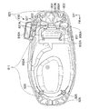
図1に示すように、後部フェンダ69は、後輪WRの上方及び後方を覆っており、図11、図12に示すように、基部691と後方延出部692とを有する。基部691と後方延出部692とは一体成形されており、基部691は、後輪WRの上方に配置され、後方延出部692は、後輪WRの後方且つ上方に配置されている。   As shown in FIG. 1, the rear fender 69 covers the upper and rear sides of the rear wheel WR, and has a base 691 and a rear extension 692 as shown in FIGS. 11 and 12. The base portion 691 and the rear extension portion 692 are integrally formed, the base portion 691 is disposed above the rear wheel WR, and the rear extension portion 692 is disposed behind and above the rear wheel WR.

図13に示すように、後部フェンダ69の基部691の後部は、上方へ突出する後部ステー接続部693を有する。後部ステー接続部693には、後部ステー168の下端部が、ボルト697により締結され、固定されている。また、図11、図12に示すように、左右方向における基部691の前部の両側は、それぞれ上方へ突出するシートレール接続部694を有する。シートレール接続部694には、それぞれシートレール14から下方へ延出する後部フェンダ接続部144が、ボルト695により締結され、固定されている。後部フェンダ接続部144は、図16に示すように、後述するクロスメンバ160の両端部よりも車幅方向(左右方向)外方に配置されている。即ち、後部フェンダ69の前部の左右両側は、それぞれ後部フェンダ接続部144を介してシートレール14に締結される。また、図15等に示すように、後部フェンダ69の基部691の上面には、上方へ突出するバッテリ当接凸部696が設けられている。バッテリ当接凸部696は、前後の一対配置されており、左右方向に直交する面で切った断面は、台形形状を有している。   As shown in FIG. 13, the rear portion of the base portion 691 of the rear fender 69 has a rear stay connecting portion 693 protruding upward. A lower end portion of the rear stay 168 is fastened and fixed to the rear stay connecting portion 693 by a bolt 697. 11 and 12, both sides of the front portion of the base portion 691 in the left-right direction have seat rail connecting portions 694 that protrude upward. A rear fender connection portion 144 that extends downward from the seat rail 14 is fastened and fixed to the seat rail connection portion 694 by bolts 695. As shown in FIG. 16, the rear fender connecting portion 144 is disposed outward in the vehicle width direction (left-right direction) with respect to both end portions of a cross member 160 described later. That is, the left and right sides of the front portion of the rear fender 69 are fastened to the seat rail 14 via the rear fender connection portion 144, respectively. Further, as shown in FIG. 15 and the like, a battery contact protrusion 696 that protrudes upward is provided on the upper surface of the base 691 of the rear fender 69. The battery contact protrusions 696 are arranged in a pair of front and rear, and a cross section cut by a plane orthogonal to the left-right direction has a trapezoidal shape.

図11等に示すように、左側のシートレール14の後部フェンダ接続部144よりも後方には、上端支持ブラケット141が形成されている。図16に示すように、上端支持ブラケット141は、クッション支持用ガセット141Aと、支持板状部141Bとを有する。クッション支持用ガセット141Aは、管状部161の左端部近傍と左側のシートレール14とを斜めに掛け渡すように形成されている。支持板状部141Bは、クッション支持用ガセット141Aの下面から下方へ対をなして延びて、図11等に示すように、それぞれ上端支持ブラケット141の側方視全体で略三角形状を有している。   As shown in FIG. 11 and the like, an upper end support bracket 141 is formed behind the rear fender connecting portion 144 of the left seat rail 14. As shown in FIG. 16, the upper end support bracket 141 includes a cushion support gusset 141A and a support plate-like portion 141B. The cushion-supporting gusset 141A is formed so that the vicinity of the left end portion of the tubular portion 161 and the left seat rail 14 are slanted. The support plate-like portion 141B extends downward from the lower surface of the cushion support gusset 141A and has a substantially triangular shape in the entire side view of the upper end support bracket 141 as shown in FIG. Yes.

図16に示すように、一対の支持板状部141B間には、リアクッション26の上端部が配置される。支持板状部141Bには、左右方向に貫通する貫通孔(図示せず)が形成されており、この貫通孔と、リアクッション26の上端部に形成された貫通孔(図示せず)とを、ボルト141Cが貫通している。これにより、リアクッション26の上端部は、クッション支持部としての上端支持ブラケット141を介して、シートレール14の一側としての左側のシートレール14に連結されている。   As shown in FIG. 16, the upper end portion of the rear cushion 26 is disposed between the pair of support plate-like portions 141B. The support plate-like portion 141B is formed with a through hole (not shown) penetrating in the left-right direction, and this through hole and a through hole (not shown) formed at the upper end of the rear cushion 26 are formed. The bolt 141C has penetrated. Thereby, the upper end part of the rear cushion 26 is connected to the left seat rail 14 as one side of the seat rail 14 via the upper end support bracket 141 as a cushion support part.

図17に示すように、バッテリステー152は、幅方向周回部153と、前後方向周回部154と、を有し、バッテリ151の一部を覆っている。幅方向周回部153は、下部帯状金属板153Aと、上部帯状金属板153Bとを有する。下部帯状金属板153Aは、上方へ開口するコの字状を有する。上部帯状金属板153Bは、下部帯状金属板153Aの開口を閉塞する。この構成により、幅方向周回部153は、略直方体形状を有するバッテリ151の前後方向中央部を幅方向に一周する。   As shown in FIG. 17, the battery stay 152 has a width direction surrounding portion 153 and a front and rear direction surrounding portion 154 and covers a part of the battery 151. The widthwise circumferential portion 153 includes a lower strip metal plate 153A and an upper strip metal plate 153B. The lower belt-like metal plate 153A has a U-shape that opens upward. Upper strip metal plate 153B closes the opening of lower strip metal plate 153A. With this configuration, the widthwise circumferential portion 153 goes around the central portion in the front-rear direction of the battery 151 having a substantially rectangular parallelepiped shape in the width direction.

図17(a)に示すように、具体的には、上部帯状金属板153Bの左端部は、下方へ折り曲げられ、下部帯状金属板153Aの左端部上部に固定されている。上部帯状金属板153Bの右端部は、上方へ折り曲げられ、下部帯状金属板153Aの右端部上部にボルト153Cにより固定されている。また、上部帯状金属板153Bの右端部と、下部帯状金属板153Aの右端部上部とは、当該ボルト153Cによって、クロスメンバ160に設けられたバッテリステー右側支持部167(図13等参照)に固定されている。   As shown in FIG. 17A, specifically, the left end portion of the upper strip metal plate 153B is bent downward and fixed to the upper left end portion of the lower strip metal plate 153A. The right end portion of the upper strip metal plate 153B is bent upward, and is fixed to the upper portion of the right end portion of the lower strip metal plate 153A by a bolt 153C. Further, the right end portion of the upper strip metal plate 153B and the upper right end portion of the lower strip metal plate 153A are fixed to the battery stay right support portion 167 (see FIG. 13 and the like) provided on the cross member 160 by the bolt 153C. Has been.

図13、図14、図17等に示すように、前後方向周回部154は、後部帯状金属板154Aと、前部帯状金属板154Bとを有する。後部帯状金属板154Aは、前方へ開口するコの字状を有する。前部帯状金属板154Bは、後部帯状金属板154Aの開口を閉塞する。この構成により、前後方向周回部154は、略直方体形状を有するバッテリ151の幅方向中央部を前後方向に一周する。   As shown in FIGS. 13, 14, 17, etc., the front-rear direction circulating portion 154 includes a rear band-shaped metal plate 154 </ b> A and a front band-shaped metal plate 154 </ b> B. The rear band metal plate 154A has a U-shape that opens forward. The front strip metal plate 154B closes the opening of the rear strip metal plate 154A. With this configuration, the front-rear direction turning portion 154 goes around the center portion in the width direction of the battery 151 having a substantially rectangular parallelepiped shape in the front-rear direction.

図14に示すように、具体的には、前部帯状金属板154Bの下端部は、後部帯状金属板154Aの下側の前端部に係合する。後部帯状金属板154Aの上側の前端部は、上方へ折り曲げられ、前部帯状金属板154Bの上端部にボルト154Cにより固定されている。後部帯状金属板154Aの後部には、後方へ突出する後部ステー固定部154Dが設けられている。後部ステー固定部154Dは、後部ステー168の長手方向における途中の部分から前方へ突出するバッテリ固定部168Aに、ボルト154Eにより固定されている。   As shown in FIG. 14, specifically, the lower end portion of the front band-shaped metal plate 154B engages with the lower front end portion of the rear band-shaped metal plate 154A. The upper front end portion of the rear band-shaped metal plate 154A is bent upward and fixed to the upper end portion of the front band-shaped metal plate 154B by a bolt 154C. A rear stay fixing portion 154D that protrudes rearward is provided at the rear portion of the rear band-shaped metal plate 154A. The rear stay fixing portion 154D is fixed to the battery fixing portion 168A protruding forward from a middle portion in the longitudinal direction of the rear stay 168 by a bolt 154E.

以上のように、バッテリステー152は、後部ステー168に固定されると共に、シートレール14の他側としての右側のシートレール14に設けられた固定部としてのバッテリステー右側支持部167に固定されている。この構成により、バッテリステー152は、バッテリ151の前後左右方向を位置決めするように設けられている。また、バッテリ151の下面は、後部フェンダ69の基部691の上面の当接部としてのバッテリ当接凸部696に当接しており、バッテリ151は、後部フェンダ69の上方に配置されている。   As described above, the battery stay 152 is fixed to the rear stay 168 and fixed to the battery stay right support portion 167 as a fixing portion provided on the right seat rail 14 as the other side of the seat rail 14. Yes. With this configuration, the battery stay 152 is provided so as to position the battery 151 in the front-rear and left-right directions. Further, the lower surface of the battery 151 is in contact with a battery contact convex portion 696 as a contact portion of the upper surface of the base 691 of the rear fender 69, and the battery 151 is disposed above the rear fender 69.

次に、自動二輪車1のキャリア締結構造について、図1及び図18〜図25を参照しながら説明する。
図18は、自動二輪車1の後部からシート27、リアサイドカバー67、収納ボックス810等を取り外した様子を示す斜視図である。図19は、自動二輪車1の後部からシート27、リアサイドカバー67、収納ボックス810等を取り外した様子を示す平面図である。図20は、自動二輪車1のキャリア850及びその周辺を示す背面図である。図21は、自動二輪車1の後部からシート27を取り外した様子を示す斜視図である。図22は、自動二輪車1の後部からリアセンターカバー855を取り外した様子を示す背面図である。図24は、自動二輪車1のキャリア締結構造を構成するリアセンターカバー855を示す上方斜視図である。図25は、自動二輪車1のキャリア締結構造を構成するリアセンターカバー855を示す下方斜視図である。図26は、図2のa−a線断面図である。
Next, the carrier fastening structure of the motorcycle 1 will be described with reference to FIGS. 1 and 18 to 25.
FIG. 18 is a perspective view showing a state in which the seat 27, the rear side cover 67, the storage box 810, and the like are removed from the rear part of the motorcycle 1. FIG. 19 is a plan view showing a state in which the seat 27, the rear side cover 67, the storage box 810, and the like are removed from the rear part of the motorcycle 1. FIG. FIG. 20 is a rear view showing the carrier 850 of the motorcycle 1 and its periphery. FIG. 21 is a perspective view showing a state in which the seat 27 is removed from the rear part of the motorcycle 1. FIG. 22 is a rear view showing a state in which the rear center cover 855 is removed from the rear part of the motorcycle 1. FIG. 24 is an upper perspective view showing the rear center cover 855 constituting the carrier fastening structure of the motorcycle 1. FIG. 25 is a lower perspective view showing the rear center cover 855 constituting the carrier fastening structure of the motorcycle 1. 26 is a cross-sectional view taken along the line aa in FIG.

自動二輪車1のキャリア締結構造は、シート27と、テールライトユニット840と、リアカバーとしてのリアサイドカバー67と、キャリア850と、シートレール14と、を有する。   The carrier fastening structure of the motorcycle 1 includes a seat 27, a taillight unit 840, a rear side cover 67 as a rear cover, a carrier 850, and a seat rail 14.

図1に示すように、テールライトユニット840は、自動二輪車1の後部に配置されており、バッテリ151に電気的に接続されている。テールライトユニット840は、リアサイドカバー67の左側部67A及びリアサイドカバー67の右側部67Bと一体に組み立てられるように構成されている。自動二輪車1の製造工程においては、収納ボックス810がフレーム10のシートレール14に固定された後に、テールライトユニット840、リアサイドカバー67の左側部67A、及び、リアサイドカバー67の右側部67Bが一体に組み立てられたものが、収納ボックス810の上から取り付けられる。   As shown in FIG. 1, the tail light unit 840 is disposed at the rear part of the motorcycle 1 and is electrically connected to the battery 151. The tail light unit 840 is configured to be assembled integrally with the left side portion 67A of the rear side cover 67 and the right side portion 67B of the rear side cover 67. In the manufacturing process of the motorcycle 1, after the storage box 810 is fixed to the seat rail 14 of the frame 10, the tail light unit 840, the left side portion 67A of the rear side cover 67, and the right side portion 67B of the rear side cover 67 are integrated. The assembled one is attached from above the storage box 810.

テールライトユニット840は、図20等に示すように、後方視で、略U字形状を有している。即ち、テールライトユニット840は、上部において、下方に凹む凹部841を有する。凹部841は、前後方向において、クロスメンバ160の板状後面部166の裏面に対向している。   As shown in FIG. 20 and the like, the tail light unit 840 has a substantially U shape in the rear view. That is, the tail light unit 840 has a concave portion 841 that is recessed downward in the upper portion. The recess 841 faces the back surface of the plate-like rear surface portion 166 of the cross member 160 in the front-rear direction.

図18〜図22に示すように、キャリア850は、クロスメンバ固定部851と、後方延出部852と、荷物載置部853とを有する。図22に示すように、クロスメンバ固定部851は、テールライトユニット840とクロスメンバ160との固定部166Cを避けるように、下方へ開口する略コの字形状の板状を有しており、テールライトユニット840の凹部841に対向するクロスメンバ160の板状後面部166の裏面166Bに、後方から面で当接している。そして、このように面で当接した状態で、クロスメンバ固定部851の左右両端部は、図22に示すように、それぞれ2つずつ、計4つのボルト854により板状後面部166に固定されている。   As illustrated in FIGS. 18 to 22, the carrier 850 includes a cross member fixing portion 851, a rear extension 852, and a luggage placement portion 853. As shown in FIG. 22, the cross member fixing portion 851 has a substantially U-shaped plate shape that opens downward so as to avoid the fixing portion 166C between the tail light unit 840 and the cross member 160. The rear surface 166B of the plate-like rear surface portion 166 of the cross member 160 facing the concave portion 841 of the tail light unit 840 is in contact with the surface from the rear. In this state where the surfaces abut, the left and right end portions of the cross member fixing portion 851 are each fixed to the plate-like rear surface portion 166 by a total of four bolts 854, as shown in FIG. ing.

これにより、キャリア850は、凹部841に配置され、クロスメンバ160に固定されている。また、テールライトユニット840の凹部841は、シート27の後部の下縁とテールライトユニット840の上縁との間に位置するため、キャリア850は、シート27の後部の下縁とテールライトユニット840の上縁との間に配置される。具体的には、キャリア850を構成する延出部852が、凹部841において、シート27とテールライトユニット840との間の空間を通過するように設けられる。   Thus, the carrier 850 is disposed in the recess 841 and fixed to the cross member 160. Further, since the concave portion 841 of the tail light unit 840 is located between the lower edge of the rear portion of the seat 27 and the upper edge of the tail light unit 840, the carrier 850 has the lower edge of the rear portion of the seat 27 and the tail light unit 840. It is arrange | positioned between the upper edges. Specifically, the extending portion 852 constituting the carrier 850 is provided in the recessed portion 841 so as to pass through the space between the seat 27 and the tail light unit 840.

後方延出部852は、クロスメンバ固定部851から後方へ延出している。後方延出部852は、車幅方向(左右方向)に平行な位置関係を有する一対の板状を有している。後方延出部852の途中には、それぞれ前後方向に長い長円形状の貫通孔852Aが形成されている。後方延出部852の上端縁及び下端縁には、それぞれ左右方向に平行な面を有する略水平縁部852Bが設けられている。後方延出部852の後端部の上部は、それぞれ左右方向に拡幅する拡幅部852Cを有している。   The rear extension 852 extends rearward from the cross member fixing part 851. The rear extension 852 has a pair of plate shapes having a positional relationship parallel to the vehicle width direction (left-right direction). An oval through hole 852A that is long in the front-rear direction is formed in the middle of the rear extension 852. A substantially horizontal edge 852 </ b> B having a surface parallel to the left-right direction is provided on the upper edge and the lower edge of the rear extension 852. The upper part of the rear end portion of the rear extension 852 has a widened portion 852C that widens in the left-right direction.

荷物載置部853は、図19に示すように、平面視で略長方形状の板状を有しており、略水平の位置関係を有して、後方延出部852の延出端部の拡幅部852Cに一体で接続されている。従って、図1に示すように、キャリア850は、シート27の後方に配置されている。図19に示すように、平面視で荷物載置部853の中央部には、上下方向に貫通する貫通孔853Aが形成されている。荷物載置部853の周縁部には、下方向に延びる面を有する略鉛直縁部853Bが設けられている。   As shown in FIG. 19, the luggage placement portion 853 has a substantially rectangular plate shape in plan view, has a substantially horizontal positional relationship, and has an extension end portion of the rear extension portion 852. It is integrally connected to the widened portion 852C. Therefore, as shown in FIG. 1, the carrier 850 is disposed behind the seat 27. As shown in FIG. 19, a through hole 853 </ b> A penetrating in the vertical direction is formed in the center portion of the luggage placing portion 853 in a plan view. A substantially vertical edge portion 853 </ b> B having a downwardly extending surface is provided on the peripheral edge portion of the luggage placement portion 853.

図22と、図20及び図21とを対比して分かるように、クロスメンバ固定部851は、リアセンターカバー855により覆われている。リアセンターカバー855は、シート27の下方とテールライトユニット840の上方との間に形成され、固定されている。リアセンターカバー855の下部は、凹部841内に配置されている。リアセンターカバー855の上部は、凹部841の上方であってシート27の下側に配置されている。   As can be seen by comparing FIG. 22 with FIGS. 20 and 21, the cross member fixing portion 851 is covered with a rear center cover 855. The rear center cover 855 is formed and fixed between the lower side of the seat 27 and the upper side of the tail light unit 840. A lower portion of the rear center cover 855 is disposed in the recess 841. The upper portion of the rear center cover 855 is disposed above the recess 841 and below the seat 27.

図24及び図25に示すように、リアセンターカバー855は、2本の溝部855Aを有する略櫛状を有している。図20に示すように、溝部855Aには、後方延出部852が配置される。図24及び図25に示すように、リアセンターカバー855は、延出部固定部855Bを有する。延出部固定部855Bは、リアセンターカバー855の上端部の左右両端部に設けられており、図5、図21に示すように、シート27の下方で収納ボックス810の延出部821の後端部に、クリップ856Aにより係合、固定される。より具体的には、延出部固定部855Bは、前方に延出しており、図21に示すように、貫通孔により構成されるクリップ係止部856が、収納ボックス810の延出部821の後端部に設けられたクリップ856A(図6参照)によって収納ボックス810の延出部821の後端部に固定される。   As shown in FIGS. 24 and 25, the rear center cover 855 has a substantially comb shape having two groove portions 855A. As shown in FIG. 20, a rear extension 852 is disposed in the groove 855A. As shown in FIGS. 24 and 25, the rear center cover 855 has an extending portion fixing portion 855B. The extension portion fixing portion 855B is provided at both left and right end portions of the upper end portion of the rear center cover 855. As shown in FIGS. 5 and 21, the extension portion fixing portion 855B is disposed below the seat 27 and behind the extension portion 821 of the storage box 810. The end is engaged and fixed by a clip 856A. More specifically, the extension portion fixing portion 855B extends forward, and as shown in FIG. 21, the clip locking portion 856 formed by a through hole is provided on the extension portion 821 of the storage box 810. The clip 856A (see FIG. 6) provided at the rear end is fixed to the rear end of the extended portion 821 of the storage box 810.

また、図24及び図25に示すように、リアセンターカバー855は、下方へ向かって後方へ延出している。より具体的には、リアセンターカバー855は、図23に示すように、後方延出部852の上端相当位置から後方へ斜めに下がり、上下方向における後方延出部852の略中央位置から前方に湾曲している。即ち、リアセンターカバー855の下端部は、自動二輪車の内側である前方へ湾曲して凹んだ湾曲面855Cを有している。   Further, as shown in FIGS. 24 and 25, the rear center cover 855 extends rearward downward. More specifically, as shown in FIG. 23, the rear center cover 855 is obliquely lowered rearward from a position corresponding to the upper end of the rearward extension 852 and forwardly from a substantially central position of the rearward extension 852 in the vertical direction. It is curved. That is, the lower end portion of the rear center cover 855 has a curved surface 855 </ b> C that is curved forward and recessed inside the motorcycle.

湾曲面855Cは、テールライトユニット840に形成された凹部841に沿った形状を有している。図25に示すように、リアセンターカバー855の下端部の中央部には、前方へ突出するユニット係合突部855Dが設けられている。ユニット係合突部855Dは、図25に示すように、下方へ開口するコの字状を有しており、左右方向におけるテールライトユニット840の凹部841の中央に形成された直方体形状の穴842(図22参照)に係合する。これにより、テールライトユニット840とリアセンターカバー855とは係合する。   The curved surface 855 </ b> C has a shape along the concave portion 841 formed in the tail light unit 840. As shown in FIG. 25, a unit engagement protrusion 855D protruding forward is provided at the center of the lower end of the rear center cover 855. As shown in FIG. 25, the unit engagement protrusion 855D has a U-shape opening downward, and a rectangular parallelepiped hole 842 formed in the center of the recess 841 of the tail light unit 840 in the left-right direction. (See FIG. 22). Thereby, the tail light unit 840 and the rear center cover 855 are engaged.

また、図25に示すように、延出部固定部855Bと、湾曲面855Cとを結ぶリアセンターカバー855の上下方向における中央部には、リアサイドカバー係合突部855Eと、側方ユニット係合突部855Fとが、リアセンターカバー855と一体成形されて設けられている。リアサイドカバー係合突部855Eは、リアセンターカバー855の左右端縁近傍から前方へ向かって延出する板状を有する。また、側方ユニット係合突部855Fは、リアサイドカバー係合突部855Eよりも車幅方向(左右方向)内方に位置して形成されており、前方へ向かって延出する板状を有する。   Further, as shown in FIG. 25, a rear side cover engagement protrusion 855E and a side unit engagement are provided at the center in the vertical direction of the rear center cover 855 connecting the extension portion fixing portion 855B and the curved surface 855C. The protrusion 855F is provided integrally with the rear center cover 855. The rear side cover engagement protrusion 855E has a plate shape extending forward from the vicinity of the left and right edges of the rear center cover 855. The side unit engagement protrusion 855F is formed to be located inward of the rear side cover engagement protrusion 855E in the vehicle width direction (left-right direction) and has a plate shape extending forward. .

テールライトユニット840の幅方向の範囲内で左側部67Aと右側部67Bとに分割されているリアサイドカバー67の分割部分67C、67D(図22参照)には、係合穴67E、67Fがそれぞれ形成されているのであるが、この係合穴67E、67Fにリアサイドカバー係合突部855E(図25参照)は、係合する。また、凹部841を形成するテールライトユニット840の部分の左右両端部分には、係合穴840A、840B(図22参照)が形成されているのであるが、この係合穴840A、840Bに側方ユニット係合突部855F(図25参照)は、係合する。これらの係合により、リアセンターカバー855は、リアサイドカバー67及びテールライトユニット840に固定されている。ユニット係合突部855D、リアサイドカバー係合突部855E、側方ユニット係合突部855Fは、リアセンターカバー固定部を構成する。   Engagement holes 67E and 67F are formed in the split portions 67C and 67D (see FIG. 22) of the rear side cover 67 which are divided into the left side portion 67A and the right side portion 67B within the range of the tail light unit 840 in the width direction. However, the rear side cover engagement protrusion 855E (see FIG. 25) engages with the engagement holes 67E and 67F. Engagement holes 840A and 840B (see FIG. 22) are formed in the left and right end portions of the tail light unit 840 that forms the recess 841, and the engagement holes 840A and 840B are laterally formed. The unit engagement protrusion 855F (see FIG. 25) is engaged. With these engagements, the rear center cover 855 is fixed to the rear side cover 67 and the tail light unit 840. The unit engagement protrusion 855D, the rear side cover engagement protrusion 855E, and the side unit engagement protrusion 855F constitute a rear center cover fixing portion.

リアサイドカバー67は、テールライトユニット840の幅方向の範囲内で左側部67Aと右側部67Bとに分割されているが、この分割されている部分67C、67D及びクロスメンバ固定部851は、リアセンターカバー855により覆われている。そして、リアセンターカバー855が外されることにより、クロスメンバ160に固定されるキャリア850の部分であるクロスメンバ固定部851が露出すると共に、リアサイドカバー67が右側部67Bと左側部67Aとに分割されている部分が露出する。   The rear side cover 67 is divided into a left side portion 67A and a right side portion 67B within the range of the tail light unit 840 in the width direction. The divided portions 67C and 67D and the cross member fixing portion 851 are arranged at the rear center. Covered with a cover 855. When the rear center cover 855 is removed, the cross member fixing portion 851 that is a portion of the carrier 850 fixed to the cross member 160 is exposed, and the rear side cover 67 is divided into the right side portion 67B and the left side portion 67A. The exposed part is exposed.

以上説明した本実施形態の自動二輪車1の鞍乗型車両の後部フェンダ支持構造によれば、例えば、以下のような効果が奏される。   According to the rear fender support structure of the straddle-type vehicle of the motorcycle 1 according to the present embodiment described above, for example, the following effects are exhibited.

本実施形態においては、バッテリ151の一部を覆い、バッテリ151を保持するバッテリステー152を備え、バッテリステー152は、シートレール14に固定される。このため、後部フェンダ69によりバッテリステー152を支持する必要がなくなり、後部フェンダ69にバッテリ搭載のための、強度・剛性を低減することができ、後部フェンダ69の軽量化を図ることができる。   In the present embodiment, a battery stay 152 that covers a part of the battery 151 and holds the battery 151 is provided, and the battery stay 152 is fixed to the seat rail 14. Therefore, there is no need to support the battery stay 152 by the rear fender 69, the strength and rigidity for mounting the battery on the rear fender 69 can be reduced, and the weight of the rear fender 69 can be reduced.

本実施形態においては、後部フェンダ69は、シートレール14から延出する後部ステー168に固定され、バッテリステー152は、後部ステー168に固定されるため、後部ステー168を補強してバッテリ151を支持する代わりに、後部ステー168の補強をバッテリステー152で行うことができる。このため、後部ステー168の軽量化を図ることができる。   In the present embodiment, the rear fender 69 is fixed to the rear stay 168 extending from the seat rail 14, and the battery stay 152 is fixed to the rear stay 168, so that the rear stay 168 is reinforced to support the battery 151. Instead, the rear stay 168 can be reinforced by the battery stay 152. For this reason, the weight reduction of the rear stay 168 can be achieved.

本実施形態においては、後部ステー168は、左右一対で形成されたシートレール14の間を締結する後部のクロスメンバ160に連結されると共に、車幅方向中心に設けられる。このため、後部フェンダ69を車幅方向中心に設けられる後部ステー168によって左右のバランスを取りながら固定することができる。このため、後部フェンダ69の固定箇所の数を低減して、生産性を向上させることができる。   In the present embodiment, the rear stay 168 is connected to a rear cross member 160 that fastens between a pair of left and right seat rails 14 and is provided at the center in the vehicle width direction. For this reason, the rear fender 69 can be fixed while maintaining the left and right balance by the rear stay 168 provided at the center in the vehicle width direction. For this reason, the number of fixing parts of the rear fender 69 can be reduced and productivity can be improved.

本実施形態においては、バッテリステー152は、バッテリ151の前後左右方向を位置決めするように設けられ、後部フェンダ69は、バッテリ151の下面と当接する当接部としての当接凸部696を有する。このため、バッテリ151の下方向の荷重のみを後部フェンダ69で支え、前後左右方向の荷重をバッテリステー152で支えて、バッテリ151の荷重を後部フェンダ69とバッテリステー152とで分担することができる。このため、バッテリステー152と後部フェンダ69の剛性の最適化を図ることができ、全体として軽量化を図ることができる。   In the present embodiment, the battery stay 152 is provided so as to position the battery 151 in the front-rear and left-right directions, and the rear fender 69 has a contact protrusion 696 as a contact portion that contacts the lower surface of the battery 151. Therefore, only the downward load of the battery 151 is supported by the rear fender 69, the load of the front and rear, right and left directions is supported by the battery stay 152, and the load of the battery 151 can be shared by the rear fender 69 and the battery stay 152. . For this reason, the rigidity of the battery stay 152 and the rear fender 69 can be optimized, and the overall weight can be reduced.

本実施形態においては、シートレール14は、左右一対で形成され、シートレール14の一側に、後輪WRを弾性的に支持するリアクッション26を支持するクッション支持部としての上端支持ブラケット141を有すると共に、シートレール14の他側に、バッテリステー152を固定する固定部としてのバッテリステー右側支持部167を有する。このため、左右一対のシートレール14でそれぞれ荷重を分担して支持することができる。このため、シートレール14の剛性バランスを最適した上で、それぞれの剛性を利用した補機の固定が可能となり、車両性能を向上させながら、軽量化を図ることができる。   In the present embodiment, the seat rail 14 is formed as a pair of left and right, and an upper end support bracket 141 as a cushion support portion that supports the rear cushion 26 that elastically supports the rear wheel WR is formed on one side of the seat rail 14. And a battery stay right support portion 167 as a fixing portion for fixing the battery stay 152 on the other side of the seat rail 14. For this reason, the load can be shared and supported by the pair of left and right seat rails 14. For this reason, after optimizing the rigidity balance of the seat rail 14, it is possible to fix the auxiliary machines using the respective rigidity, and it is possible to reduce the weight while improving the vehicle performance.

本実施形態においては、シートレール14は、上方かつ後方に延出するように形成されると共に、後部フェンダ69の前部の左右両側は、シートレール14に締結される。このため、シートレール14の低い位置で後部フェンダ69の左右両側をシートレール14に締結して固定することができる。これにより、締結のための部材を大型化することなく形成でき、この結果、軽量化を図ることができる。   In the present embodiment, the seat rail 14 is formed to extend upward and rearward, and the left and right sides of the front portion of the rear fender 69 are fastened to the seat rail 14. Therefore, the left and right sides of the rear fender 69 can be fastened and fixed to the seat rail 14 at a low position of the seat rail 14. Thereby, it can form without enlarging the member for fastening, As a result, weight reduction can be achieved.

次に、本発明を、スクータ型の自動二輪車に適用した場合の第2実施形態について、図27を参照しながら説明する。第2実施形態では、後部フェンダ69はバッテリステー152Gにより支持されており、第1実施形態における後部ステー168に代えて後部支持部154Jが設けられている点において、第1実施形態とは異なる。これ以外の構成は、第1実施形態と同様であり、従って、第1実施形態と同様の構成からは同様の効果を得ることができる。同一の部材については、同一の符号を付して、説明を省略する。   Next, a second embodiment when the present invention is applied to a scooter type motorcycle will be described with reference to FIG. In the second embodiment, the rear fender 69 is supported by a battery stay 152G, and is different from the first embodiment in that a rear support portion 154J is provided instead of the rear stay 168 in the first embodiment. The other configuration is the same as that of the first embodiment, and therefore the same effect can be obtained from the same configuration as that of the first embodiment. About the same member, the same code | symbol is attached | subjected and description is abbreviate | omitted.

バッテリステー152Gは、第1実施形態の後部帯状金属板154Aに代えて、後部帯状金属板154Gを有する。これ以外の構成は、第1実施形態のバッテリステー152と同様である。後部帯状金属板154Gには、前方に向けて開口するU字形状の後部支持部154Jが一体で接続されている。後部支持部154Jの後部は、ボルト154Eにより後部ステー接続部693に締結されている。これにより、後部フェンダ69の基部691の後部は、バッテリステー152Gにより、フレーム10に支持されている。   The battery stay 152G includes a rear band metal plate 154G instead of the rear band metal plate 154A of the first embodiment. Other configurations are the same as the battery stay 152 of the first embodiment. A U-shaped rear support portion 154J that opens toward the front is integrally connected to the rear band-shaped metal plate 154G. The rear part of the rear support part 154J is fastened to the rear stay connection part 693 by a bolt 154E. Accordingly, the rear portion of the base portion 691 of the rear fender 69 is supported by the frame 10 by the battery stay 152G.

以上説明した第2実施形態の自動二輪車の鞍乗型車両の後部フェンダ支持構造によれば、例えば、以下のような効果が奏される。   According to the rear fender support structure of the saddle riding type motorcycle of the second embodiment described above, for example, the following effects can be achieved.

本実施形態においては、基部691の後部は、バッテリステー152Gに締結されるため、第1実施形態における基部691の後部を固定するための後部ステー168を設ける必要がなくなる。このため、基部691の後部を固定する後部ステー168を設けない分、軽量化を図ることができる。   In the present embodiment, since the rear portion of the base portion 691 is fastened to the battery stay 152G, it is not necessary to provide the rear stay 168 for fixing the rear portion of the base portion 691 in the first embodiment. For this reason, it is possible to reduce the weight because the rear stay 168 for fixing the rear portion of the base portion 691 is not provided.

以上、本発明の好ましい各実施形態について説明したが、本発明は、上述した実施形態に制限されることなく、種々の形態で実施することができる。例えば、本実施形態では、一対のシートレール14は、シート27の下方に設けられ、収納ボックス810等を介して間接的にシート27を支持したが、この構成に限定されない。例えば、一対のシートレールは、直接的にシートを支持してもよい。   The preferred embodiments of the present invention have been described above, but the present invention is not limited to the above-described embodiments, and can be implemented in various forms. For example, in the present embodiment, the pair of seat rails 14 is provided below the seat 27 and indirectly supports the seat 27 via the storage box 810 or the like, but is not limited to this configuration. For example, the pair of seat rails may directly support the seat.

また、本実施形態では、バッテリステー152は、バッテリ151の一部を覆っていたが、この構成に限定されない。例えば、バッテリ151の全部を覆っていてもよい。   Further, in the present embodiment, the battery stay 152 covers a part of the battery 151, but is not limited to this configuration. For example, the entire battery 151 may be covered.

また、上記実施形態では、本発明を、エンジン(内燃機関)で発生する動力により後輪を回転駆動させて走行する自動二輪車に適用した例について説明したが、本発明の適用はこれに限定されない。すなわち、本発明を、電動モータで発生する動力のみにより後輪を回転駆動させて走行する電動二輪車に適用することもできる。また、エンジンで発生させた動力、及び電動モータで発生させた動力の2つの動力を組み合わせて後輪を回転駆動させて走行するハイブリッド型の鞍乗型車両に適用することもできる。   In the above-described embodiment, the example in which the present invention is applied to a motorcycle that travels by rotating the rear wheels by power generated by an engine (internal combustion engine) has been described. However, the application of the present invention is not limited thereto. . That is, the present invention can also be applied to an electric motorcycle that travels by rotating the rear wheels only with power generated by the electric motor. Further, the present invention can also be applied to a hybrid straddle-type vehicle that travels by rotating the rear wheels by combining the power generated by the engine and the power generated by the electric motor.

更に、本発明は、乗員が着座するシートを備えた車両であれば、スクータ型の鞍乗型車両に限らず、モータサイクル型、カブ型の鞍乗型車両に適用することもできる。また、乗員が着座するシートを備えた車両であれば、三輪又は四輪の鞍乗型車両に適用することもできる。すなわち、鞍乗型車両は、乗員が車体に跨って乗車する乗り物全般を含む。   Furthermore, the present invention can be applied not only to a scooter type saddle type vehicle but also to a motorcycle type and a cub type saddle type vehicle as long as the vehicle includes a seat on which an occupant is seated. Further, any vehicle having a seat on which an occupant is seated can be applied to a three-wheel or four-wheel saddle riding type vehicle. That is, the saddle riding type vehicle includes all vehicles on which the occupant rides across the vehicle body.

1 自動二輪車(鞍乗型車両)
10 車体フレーム(メインフレーム)
14 シートレール
27 シート
69 後部フェンダ
151 バッテリ
152、152G バッテリステー
168 後部ステー
691 基部
692 後方延出部
160 クロスメンバ
696 バッテリ当接凸部(当接部)
26 リアクッション
141 上端支持ブラケット(クッション支持部)
167 バッテリステー右側支持部(固定部)
WR 後輪
1 Motorcycle (saddle-ride type vehicle)
10 Body frame (main frame)
14 seat rail 27 seat 69 rear fender 151 battery 152, 152G battery stay 168 rear stay 691 base 692 rear extension 160 cross member 696 battery contact convex part (contact part)
26 Rear cushion 141 Upper end support bracket (cushion support part)
167 Battery stay right side support part (fixed part)
WR rear wheel

Claims (6)

車体フレーム(10)の後部を形成し、直接的又は間接的にシート(27)を支持するシートレール(14)と、
後輪(WR)の少なくとも上方を覆う後部フェンダ(69)と、
前記後部フェンダ(69)の上方に配置されるバッテリ(151)と、を備える鞍乗型車両の後部フェンダ支持構造において、
前記バッテリ(151)の少なくとも一部を覆い、前記バッテリ(151)を保持するバッテリステー(152)を備え、
前記バッテリステー(152)は、前記シートレール(14)に固定され
前記後部フェンダ(69)は、前記シートレール(14)から延出する後部ステー(168)に固定され、
前記バッテリステー(152)は、前記後部ステー(168)に固定される鞍乗型車両の後部フェンダ支持構造。
A seat rail (14) forming the rear of the body frame (10) and supporting the seat (27) directly or indirectly;
A rear fender (69) covering at least the upper part of the rear wheel (WR);
A rear fender support structure of a straddle-type vehicle comprising a battery (151) disposed above the rear fender (69);
A battery stay (152) that covers at least a part of the battery (151) and holds the battery (151);
The battery stay (152) is fixed to the seat rail (14) ,
The rear fender (69) is fixed to a rear stay (168) extending from the seat rail (14),
The battery stays (152), a rear fender supporting structure of a straddle-type vehicle that will be fixed to the rear stay (168).
前記後部フェンダ(69)は、基部(691)と、前記基部(691)から延出して泥よけの機能を発揮する後方延出部(692)と、を有し、
基部(691)の後部は、前記バッテリステー(152G)に締結される請求項1に記載の鞍乗型車両の後部フェンダ支持構造。
The rear fender (69) has a base (691) and a rear extension (692) that extends from the base (691) and exhibits a mudguard function.
The rear fender support structure of a straddle-type vehicle according to claim 1, wherein a rear portion of the base portion (691) is fastened to the battery stay (152G).
前記後部ステー(168)は、左右一対で形成された前記シートレール(14)の間を締結する後部のクロスメンバ(160)に連結されると共に、車幅方向中心に設けられる請求項に記載の鞍乗型車両の後部フェンダ支持構造。 Said rear stay (168) is described in conjunction with the coupled to the rear of the cross member for fastening the (160) between the pair in the formed the seat rail (14), in claim 1 provided in the vehicle widthwise center Rear fender support structure for saddle-ride type vehicles. 前記バッテリステー(152)は、前記バッテリ(151)の前後左右方向を位置決めするように設けられ、
前記後部フェンダ(69)は、前記バッテリ(151)の下面と当接する当接部(696)を有する請求項1又は請求項に記載の鞍乗型車両の後部フェンダ支持構造。
The battery stay (152) is provided to position the battery (151) in the front-rear and left-right directions,
The straddle-type vehicle rear fender support structure according to claim 1 or 3 , wherein the rear fender (69) has a contact portion (696) that contacts the lower surface of the battery (151).
前記シートレール(14)は、左右一対で形成され、前記シートレール(14)の一側に、後輪(WR)を弾性的に支持するリアクッション(26)を支持するクッション支持部(141)を有すると共に、前記シートレール(14)の他側に、前記バッテリステー(152)を固定する固定部(167)を有する請求項1、請求項、請求項のいずれかに記載の鞍乗型車両の後部フェンダ支持構造。 The seat rail (14) is formed as a pair of left and right, and a cushion support portion (141) that supports a rear cushion (26) that elastically supports a rear wheel (WR) on one side of the seat rail (14). The saddle riding according to any one of claims 1, 3 and 4 , further comprising a fixing portion (167) for fixing the battery stay (152) on the other side of the seat rail (14). Support structure for rear fender of type vehicle. 前記シートレール(14)は、上方かつ後方に延出するように形成されると共に、前記後部フェンダ(69)の前部の左右両側は、前記シートレール(14)に締結される請求項1〜請求項のいずれかに記載の鞍乗型車両の後部フェンダ支持構造。
The seat rail (14) is formed so as to extend upward and rearward, and both right and left sides of a front portion of the rear fender (69) are fastened to the seat rail (14). The rear fender support structure of the saddle riding type vehicle according to any one of claims 5 to 6.
JP2013075179A 2013-03-29 2013-03-29 Rear fender support structure for saddle-ride type vehicles Active JP6132628B2 (en)

Priority Applications (2)

Application Number Priority Date Filing Date Title
JP2013075179A JP6132628B2 (en) 2013-03-29 2013-03-29 Rear fender support structure for saddle-ride type vehicles
EP14161393.5A EP2783956B1 (en) 2013-03-29 2014-03-25 Rear fender support structure for saddle type vehicle

Applications Claiming Priority (1)

Application Number Priority Date Filing Date Title
JP2013075179A JP6132628B2 (en) 2013-03-29 2013-03-29 Rear fender support structure for saddle-ride type vehicles

Publications (2)

Publication Number Publication Date
JP2014198541A JP2014198541A (en) 2014-10-23
JP6132628B2 true JP6132628B2 (en) 2017-05-24

Family

ID=50345905

Family Applications (1)

Application Number Title Priority Date Filing Date
JP2013075179A Active JP6132628B2 (en) 2013-03-29 2013-03-29 Rear fender support structure for saddle-ride type vehicles

Country Status (2)

Country Link
EP (1) EP2783956B1 (en)
JP (1) JP6132628B2 (en)

Families Citing this family (3)

* Cited by examiner, † Cited by third party
Publication number Priority date Publication date Assignee Title
JP2018140746A (en) * 2017-02-28 2018-09-13 ヤマハ発動機株式会社 Saddle type vehicle and its assembling method
EP3689724B1 (en) * 2017-09-29 2023-06-07 Honda Motor Co., Ltd. Hybrid vehicle
CN111038624B (en) * 2018-10-12 2021-02-02 雅马哈发动机株式会社 Saddle-riding type vehicle

Family Cites Families (8)

* Cited by examiner, † Cited by third party
Publication number Priority date Publication date Assignee Title
JP2891802B2 (en) * 1991-05-29 1999-05-17 本田技研工業株式会社 Battery layout structure for scooter type vehicle
JP2517529B2 (en) 1993-12-13 1996-07-24 本田技研工業株式会社 Scooter type vehicle
JP3824007B2 (en) * 2005-04-28 2006-09-20 スズキ株式会社 Scooter type vehicle
JP2009040309A (en) * 2007-08-10 2009-02-26 Yamaha Motor Co Ltd Motorcycle
JP5460511B2 (en) * 2010-07-23 2014-04-02 本田技研工業株式会社 Rear fender for vehicles
JP5690147B2 (en) * 2011-01-11 2015-03-25 本田技研工業株式会社 Saddle riding vehicle
JP5594159B2 (en) * 2011-01-18 2014-09-24 スズキ株式会社 Motorcycle battery retention structure
JP5794785B2 (en) * 2011-01-28 2015-10-14 本田技研工業株式会社 Saddle riding vehicle

Also Published As

Publication number Publication date
EP2783956B1 (en) 2020-03-18
JP2014198541A (en) 2014-10-23
EP2783956A1 (en) 2014-10-01

Similar Documents

Publication Publication Date Title
JP5332666B2 (en) Motorcycle rear fender structure and motorcycle
JP6244607B2 (en) Shroud structure of saddle riding type vehicle
JP6045903B2 (en) Motorcycle
JP5938302B2 (en) Lid lock structure for saddle-ride type vehicles
JP5423154B2 (en) Motorcycle frame cover mounting structure
JP6132628B2 (en) Rear fender support structure for saddle-ride type vehicles
JP5460511B2 (en) Rear fender for vehicles
JP2019048575A (en) Saddle-riding type vehicle
JP6187158B2 (en) Front fender reinforcement structure
JP6132627B2 (en) Gripping part structure of saddle riding type vehicle
JP6750097B2 (en) Body frame structure of saddle type vehicle
JP6151896B2 (en) Saddle-type vehicle routing structure
JP6133663B2 (en) Undercover structure for saddle riding type vehicles
JP6132629B2 (en) Carrier fastening structure for saddle riding type vehicles
JP2015047959A (en) Fuel tank mounting structure of saddle-riding type vehicle
JP2015223902A (en) Saddle riding type vehicle
JP6126936B2 (en) Battery arrangement structure for saddle riding type vehicle
JP5743840B2 (en) Rear structure of motorcycle
JP6861665B2 (en) Saddle-riding vehicle
JP5661539B2 (en) Seat structure of saddle riding type vehicle
JP2006231952A (en) Electrical equipment arranging structure
JP6033157B2 (en) Saddle-type vehicle floor step structure
JP2012232627A (en) Vehicle body cover structure of motorcycle
JP2010173579A (en) Vehicle body frame structure of motorcycle and motorcycle
JP7375662B2 (en) Storage structure for saddle type vehicles

Legal Events

Date Code Title Description
A621 Written request for application examination

Free format text: JAPANESE INTERMEDIATE CODE: A621

Effective date: 20151126

A977 Report on retrieval

Free format text: JAPANESE INTERMEDIATE CODE: A971007

Effective date: 20160923

A131 Notification of reasons for refusal

Free format text: JAPANESE INTERMEDIATE CODE: A131

Effective date: 20160927

A521 Written amendment

Free format text: JAPANESE INTERMEDIATE CODE: A523

Effective date: 20161124

TRDD Decision of grant or rejection written
A01 Written decision to grant a patent or to grant a registration (utility model)

Free format text: JAPANESE INTERMEDIATE CODE: A01

Effective date: 20170321

A61 First payment of annual fees (during grant procedure)

Free format text: JAPANESE INTERMEDIATE CODE: A61

Effective date: 20170418

R150 Certificate of patent or registration of utility model

Ref document number: 6132628

Country of ref document: JP

Free format text: JAPANESE INTERMEDIATE CODE: R150