JP6116694B2 - Magnetic field detector with magnetoresistive effect element and current detector - Google Patents
Magnetic field detector with magnetoresistive effect element and current detector Download PDFInfo
- Publication number
- JP6116694B2 JP6116694B2 JP2015534027A JP2015534027A JP6116694B2 JP 6116694 B2 JP6116694 B2 JP 6116694B2 JP 2015534027 A JP2015534027 A JP 2015534027A JP 2015534027 A JP2015534027 A JP 2015534027A JP 6116694 B2 JP6116694 B2 JP 6116694B2
- Authority
- JP
- Japan
- Prior art keywords
- magnetic field
- magnetoresistive effect
- effect element
- layer
- film
- Prior art date
- Legal status (The legal status is an assumption and is not a legal conclusion. Google has not performed a legal analysis and makes no representation as to the accuracy of the status listed.)
- Active
Links
- 230000005291 magnetic effect Effects 0.000 title claims description 232
- 230000000694 effects Effects 0.000 title claims description 206
- 230000005294 ferromagnetic effect Effects 0.000 claims description 106
- 230000005415 magnetization Effects 0.000 claims description 97
- 229910000521 B alloy Inorganic materials 0.000 claims description 23
- 239000004065 semiconductor Substances 0.000 claims description 15
- 238000012360 testing method Methods 0.000 claims description 14
- 238000010438 heat treatment Methods 0.000 claims description 6
- 239000000203 mixture Substances 0.000 claims description 4
- 230000015572 biosynthetic process Effects 0.000 claims description 2
- 239000010410 layer Substances 0.000 description 317
- 230000008859 change Effects 0.000 description 46
- CPLXHLVBOLITMK-UHFFFAOYSA-N magnesium oxide Inorganic materials [Mg]=O CPLXHLVBOLITMK-UHFFFAOYSA-N 0.000 description 35
- 239000000395 magnesium oxide Substances 0.000 description 35
- AXZKOIWUVFPNLO-UHFFFAOYSA-N magnesium;oxygen(2-) Chemical compound [O-2].[Mg+2] AXZKOIWUVFPNLO-UHFFFAOYSA-N 0.000 description 35
- 230000004048 modification Effects 0.000 description 31
- 238000012986 modification Methods 0.000 description 31
- XEEYBQQBJWHFJM-UHFFFAOYSA-N iron Substances [Fe] XEEYBQQBJWHFJM-UHFFFAOYSA-N 0.000 description 26
- 238000001514 detection method Methods 0.000 description 22
- 238000010586 diagram Methods 0.000 description 16
- 230000035945 sensitivity Effects 0.000 description 15
- 229910045601 alloy Inorganic materials 0.000 description 12
- 239000000956 alloy Substances 0.000 description 12
- 230000005290 antiferromagnetic effect Effects 0.000 description 11
- 238000004519 manufacturing process Methods 0.000 description 10
- 239000000463 material Substances 0.000 description 10
- 229910020598 Co Fe Inorganic materials 0.000 description 9
- 229910002519 Co-Fe Inorganic materials 0.000 description 9
- 239000011777 magnesium Substances 0.000 description 9
- PXHVJJICTQNCMI-UHFFFAOYSA-N nickel Substances [Ni] PXHVJJICTQNCMI-UHFFFAOYSA-N 0.000 description 9
- 230000004044 response Effects 0.000 description 9
- 238000000034 method Methods 0.000 description 8
- 239000000758 substrate Substances 0.000 description 8
- 239000012535 impurity Substances 0.000 description 7
- 229910052742 iron Inorganic materials 0.000 description 7
- 238000006243 chemical reaction Methods 0.000 description 5
- 229910017052 cobalt Inorganic materials 0.000 description 5
- 239000010941 cobalt Substances 0.000 description 5
- GUTLYIVDDKVIGB-UHFFFAOYSA-N cobalt atom Chemical compound [Co] GUTLYIVDDKVIGB-UHFFFAOYSA-N 0.000 description 5
- 230000007423 decrease Effects 0.000 description 5
- 230000010354 integration Effects 0.000 description 5
- 238000001755 magnetron sputter deposition Methods 0.000 description 5
- 239000011572 manganese Substances 0.000 description 5
- BASFCYQUMIYNBI-UHFFFAOYSA-N platinum Chemical group [Pt] BASFCYQUMIYNBI-UHFFFAOYSA-N 0.000 description 5
- QVGXLLKOCUKJST-UHFFFAOYSA-N atomic oxygen Chemical compound [O] QVGXLLKOCUKJST-UHFFFAOYSA-N 0.000 description 4
- 239000011229 interlayer Substances 0.000 description 4
- 229910052760 oxygen Inorganic materials 0.000 description 4
- 239000001301 oxygen Substances 0.000 description 4
- 229910020707 Co—Pt Inorganic materials 0.000 description 3
- FYYHWMGAXLPEAU-UHFFFAOYSA-N Magnesium Chemical compound [Mg] FYYHWMGAXLPEAU-UHFFFAOYSA-N 0.000 description 3
- 229910000914 Mn alloy Inorganic materials 0.000 description 3
- 229910052749 magnesium Inorganic materials 0.000 description 3
- 230000007246 mechanism Effects 0.000 description 3
- 229910052751 metal Inorganic materials 0.000 description 3
- 239000002184 metal Substances 0.000 description 3
- 229910052759 nickel Inorganic materials 0.000 description 3
- KDLHZDBZIXYQEI-UHFFFAOYSA-N palladium Substances [Pd] KDLHZDBZIXYQEI-UHFFFAOYSA-N 0.000 description 3
- 229920006395 saturated elastomer Polymers 0.000 description 3
- JBRZTFJDHDCESZ-UHFFFAOYSA-N AsGa Chemical compound [As]#[Ga] JBRZTFJDHDCESZ-UHFFFAOYSA-N 0.000 description 2
- 229910002601 GaN Inorganic materials 0.000 description 2
- 229910001218 Gallium arsenide Inorganic materials 0.000 description 2
- JMASRVWKEDWRBT-UHFFFAOYSA-N Gallium nitride Chemical compound [Ga]#N JMASRVWKEDWRBT-UHFFFAOYSA-N 0.000 description 2
- 229910020068 MgAl Inorganic materials 0.000 description 2
- ZDZZPLGHBXACDA-UHFFFAOYSA-N [B].[Fe].[Co] Chemical compound [B].[Fe].[Co] ZDZZPLGHBXACDA-UHFFFAOYSA-N 0.000 description 2
- 239000010949 copper Substances 0.000 description 2
- 239000013078 crystal Substances 0.000 description 2
- 230000006870 function Effects 0.000 description 2
- 238000009434 installation Methods 0.000 description 2
- 230000003993 interaction Effects 0.000 description 2
- 238000005259 measurement Methods 0.000 description 2
- 230000002093 peripheral effect Effects 0.000 description 2
- 229920002120 photoresistant polymer Polymers 0.000 description 2
- 230000004043 responsiveness Effects 0.000 description 2
- HBMJWWWQQXIZIP-UHFFFAOYSA-N silicon carbide Chemical compound [Si+]#[C-] HBMJWWWQQXIZIP-UHFFFAOYSA-N 0.000 description 2
- 229910010271 silicon carbide Inorganic materials 0.000 description 2
- 229910052596 spinel Inorganic materials 0.000 description 2
- 239000011029 spinel Substances 0.000 description 2
- -1 Al (aluminum) Chemical class 0.000 description 1
- 238000012935 Averaging Methods 0.000 description 1
- RYGMFSIKBFXOCR-UHFFFAOYSA-N Copper Chemical compound [Cu] RYGMFSIKBFXOCR-UHFFFAOYSA-N 0.000 description 1
- 229910002551 Fe-Mn Inorganic materials 0.000 description 1
- 229910003286 Ni-Mn Inorganic materials 0.000 description 1
- KJTLSVCANCCWHF-UHFFFAOYSA-N Ruthenium Chemical compound [Ru] KJTLSVCANCCWHF-UHFFFAOYSA-N 0.000 description 1
- 229910052771 Terbium Inorganic materials 0.000 description 1
- 230000009471 action Effects 0.000 description 1
- 229910052782 aluminium Inorganic materials 0.000 description 1
- XAGFODPZIPBFFR-UHFFFAOYSA-N aluminium Chemical compound [Al] XAGFODPZIPBFFR-UHFFFAOYSA-N 0.000 description 1
- 230000015556 catabolic process Effects 0.000 description 1
- 230000000295 complement effect Effects 0.000 description 1
- 229910052802 copper Inorganic materials 0.000 description 1
- 230000008878 coupling Effects 0.000 description 1
- 238000010168 coupling process Methods 0.000 description 1
- 238000005859 coupling reaction Methods 0.000 description 1
- 238000002425 crystallisation Methods 0.000 description 1
- 230000008025 crystallization Effects 0.000 description 1
- 239000003302 ferromagnetic material Substances 0.000 description 1
- 239000011521 glass Substances 0.000 description 1
- 238000009413 insulation Methods 0.000 description 1
- SHMWNGFNWYELHA-UHFFFAOYSA-N iridium manganese Chemical compound [Mn].[Ir] SHMWNGFNWYELHA-UHFFFAOYSA-N 0.000 description 1
- DALUDRGQOYMVLD-UHFFFAOYSA-N iron manganese Chemical compound [Mn].[Fe] DALUDRGQOYMVLD-UHFFFAOYSA-N 0.000 description 1
- 229910052747 lanthanoid Inorganic materials 0.000 description 1
- 150000002602 lanthanoids Chemical class 0.000 description 1
- ZAUUZASCMSWKGX-UHFFFAOYSA-N manganese nickel Chemical compound [Mn].[Ni] ZAUUZASCMSWKGX-UHFFFAOYSA-N 0.000 description 1
- IGOJMROYPFZEOR-UHFFFAOYSA-N manganese platinum Chemical compound [Mn].[Pt] IGOJMROYPFZEOR-UHFFFAOYSA-N 0.000 description 1
- 150000002739 metals Chemical class 0.000 description 1
- 238000012544 monitoring process Methods 0.000 description 1
- 230000001590 oxidative effect Effects 0.000 description 1
- 229910052763 palladium Inorganic materials 0.000 description 1
- 238000000206 photolithography Methods 0.000 description 1
- 238000001020 plasma etching Methods 0.000 description 1
- 229910052697 platinum Inorganic materials 0.000 description 1
- 230000007261 regionalization Effects 0.000 description 1
- 229910052707 ruthenium Inorganic materials 0.000 description 1
- 238000009738 saturating Methods 0.000 description 1
- 238000011896 sensitive detection Methods 0.000 description 1
- 229910052710 silicon Inorganic materials 0.000 description 1
- 239000010703 silicon Substances 0.000 description 1
- 230000000087 stabilizing effect Effects 0.000 description 1
- 229910052715 tantalum Inorganic materials 0.000 description 1
- GUVRBAGPIYLISA-UHFFFAOYSA-N tantalum atom Chemical compound [Ta] GUVRBAGPIYLISA-UHFFFAOYSA-N 0.000 description 1
- GZCRRIHWUXGPOV-UHFFFAOYSA-N terbium atom Chemical compound [Tb] GZCRRIHWUXGPOV-UHFFFAOYSA-N 0.000 description 1
- 229910052723 transition metal Inorganic materials 0.000 description 1
- 150000003624 transition metals Chemical class 0.000 description 1
- 230000005641 tunneling Effects 0.000 description 1
Images


Classifications
-
- H—ELECTRICITY
- H01—ELECTRIC ELEMENTS
- H01F—MAGNETS; INDUCTANCES; TRANSFORMERS; SELECTION OF MATERIALS FOR THEIR MAGNETIC PROPERTIES
- H01F10/00—Thin magnetic films, e.g. of one-domain structure
- H01F10/32—Spin-exchange-coupled multilayers, e.g. nanostructured superlattices
- H01F10/324—Exchange coupling of magnetic film pairs via a very thin non-magnetic spacer, e.g. by exchange with conduction electrons of the spacer
- H01F10/3286—Spin-exchange coupled multilayers having at least one layer with perpendicular magnetic anisotropy
-
- G—PHYSICS
- G01—MEASURING; TESTING
- G01R—MEASURING ELECTRIC VARIABLES; MEASURING MAGNETIC VARIABLES
- G01R33/00—Arrangements or instruments for measuring magnetic variables
- G01R33/02—Measuring direction or magnitude of magnetic fields or magnetic flux
- G01R33/06—Measuring direction or magnitude of magnetic fields or magnetic flux using galvano-magnetic devices
- G01R33/09—Magnetoresistive devices
- G01R33/093—Magnetoresistive devices using multilayer structures, e.g. giant magnetoresistance sensors
-
- G—PHYSICS
- G01—MEASURING; TESTING
- G01R—MEASURING ELECTRIC VARIABLES; MEASURING MAGNETIC VARIABLES
- G01R33/00—Arrangements or instruments for measuring magnetic variables
- G01R33/02—Measuring direction or magnitude of magnetic fields or magnetic flux
- G01R33/06—Measuring direction or magnitude of magnetic fields or magnetic flux using galvano-magnetic devices
- G01R33/09—Magnetoresistive devices
- G01R33/098—Magnetoresistive devices comprising tunnel junctions, e.g. tunnel magnetoresistance sensors
-
- H—ELECTRICITY
- H01—ELECTRIC ELEMENTS
- H01F—MAGNETS; INDUCTANCES; TRANSFORMERS; SELECTION OF MATERIALS FOR THEIR MAGNETIC PROPERTIES
- H01F10/00—Thin magnetic films, e.g. of one-domain structure
- H01F10/32—Spin-exchange-coupled multilayers, e.g. nanostructured superlattices
- H01F10/324—Exchange coupling of magnetic film pairs via a very thin non-magnetic spacer, e.g. by exchange with conduction electrons of the spacer
- H01F10/3254—Exchange coupling of magnetic film pairs via a very thin non-magnetic spacer, e.g. by exchange with conduction electrons of the spacer the spacer being semiconducting or insulating, e.g. for spin tunnel junction [STJ]
-
- H—ELECTRICITY
- H10—SEMICONDUCTOR DEVICES; ELECTRIC SOLID-STATE DEVICES NOT OTHERWISE PROVIDED FOR
- H10N—ELECTRIC SOLID-STATE DEVICES NOT OTHERWISE PROVIDED FOR
- H10N50/00—Galvanomagnetic devices
- H10N50/10—Magnetoresistive devices
Landscapes
- Physics & Mathematics (AREA)
- Chemical & Material Sciences (AREA)
- Crystallography & Structural Chemistry (AREA)
- Engineering & Computer Science (AREA)
- Power Engineering (AREA)
- Condensed Matter Physics & Semiconductors (AREA)
- General Physics & Mathematics (AREA)
- Hall/Mr Elements (AREA)
- Measuring Magnetic Variables (AREA)
- Measuring Instrument Details And Bridges, And Automatic Balancing Devices (AREA)
Description
本発明は、トンネル磁気抵抗効果を利用する磁気抵抗効果素子およびその適用製品に関するものであり、特に、性能面の向上と、製造の容易性を兼ね備えた磁気抵抗効果素子を備えた磁界検出器、および電流検出器に関するものである。 The present invention relates to a magnetoresistive effect element utilizing a tunnel magnetoresistive effect and a product to which the magnetoresistive effect element is applied, and in particular, a magnetic field detector provided with a magnetoresistive effect element having improved performance and ease of manufacture, And a current detector.
近年、磁気抵抗効果素子として、従来の巨大磁気抵抗(GMR:giant−magnetoresistance)効果よりも、大きな抵抗変化率が得られるトンネル磁気抵抗(TMR:tunneling magnetoresistance)効果を有するTMR素子を適用したメモリ、およびTMR素子の磁気ヘッドなどへの応用が進められている。 In recent years, as a magnetoresistive effect element, a memory to which a TMR element having a tunneling magnetoresistance (TMR) effect capable of obtaining a larger resistance change rate than a conventional giant magnetoresistance (GMR) effect is applied, Applications of TMR elements to magnetic heads and the like are underway.
TMR素子においては、強磁性層/絶縁層/強磁性層からなる3層膜構造が、最も単純な構造として用いられる。そして、外部磁界やスピンが偏極した電子が注入されることによって、2つの強磁性層のスピンを互いに平行あるいは反平行に設定することにより、膜面垂直方向の絶縁層を流れるトンネル電流の大きさが変化する現象が利用されている。このような現象を利用することで、TMR素子では、トンネル電流の大きさを検出することによって、2層の強磁性層の相対的な磁化方向を検出することが可能である。 In the TMR element, a three-layer film structure comprising a ferromagnetic layer / insulating layer / ferromagnetic layer is used as the simplest structure. Then, by injecting electrons with an external magnetic field or spin polarized, the spins of the two ferromagnetic layers are set parallel or antiparallel to each other, thereby increasing the tunnel current flowing through the insulating layer in the direction perpendicular to the film surface. The phenomenon that changes is used. By utilizing such a phenomenon, the TMR element can detect the relative magnetization direction of the two ferromagnetic layers by detecting the magnitude of the tunnel current.
なお、TMR素子においては、近年、トンネル絶縁層としてMgO(酸化マグネシウム)膜を用い、強磁性層としてCo−Fe−B(コバルト−鉄−ホウ素)合金膜を用いることで、100%を超える大きな抵抗変化率が得られることが知られている。さらに、MgO膜とCo−Fe−B合金膜の界面において、Co−Fe−B膜の磁化が垂直磁気異方性を示すことが知られており、主にメモリへの応用が進められている。 In recent years, in a TMR element, an MgO (magnesium oxide) film is used as a tunnel insulating layer, and a Co—Fe—B (cobalt-iron-boron) alloy film is used as a ferromagnetic layer. It is known that a resistance change rate can be obtained. Furthermore, it is known that the magnetization of the Co—Fe—B film exhibits perpendicular magnetic anisotropy at the interface between the MgO film and the Co—Fe—B alloy film, and its application to memory is being promoted mainly. .
GMR素子やTMR素子においては、一方の強磁性層を反強磁性層と交換結合させて、その強磁性層の磁化を固定して固着層とし、他方の強磁性層の磁化を外部磁界やスピン偏極電子で容易に反転することのできる自由層とする、いわゆるスピンバルブ型構造が用いられる。 In a GMR element or a TMR element, one ferromagnetic layer is exchange-coupled with an antiferromagnetic layer, and the magnetization of the ferromagnetic layer is fixed to be a fixed layer, and the magnetization of the other ferromagnetic layer is changed to an external magnetic field or spin. A so-called spin-valve structure is used, which is a free layer that can be easily inverted by polarized electrons.
スピンバルブ型構造のTMR素子は、高感度な磁界検出器として用いることが可能である。スピンバルブ型磁気抵抗効果素子に外部から磁界が印加されると、固着層の磁化は、理想的には完全に固定されているために、自由層の磁化のみが外部印加磁界に応じて回転する。これにより、2つの強磁性層の磁化の相対角が変化し、磁気抵抗効果により素子抵抗が変化する。 A TMR element having a spin valve structure can be used as a highly sensitive magnetic field detector. When a magnetic field is applied to the spin-valve magnetoresistive element from the outside, the magnetization of the pinned layer is ideally completely fixed, so that only the magnetization of the free layer rotates according to the externally applied magnetic field. . As a result, the relative angle of magnetization of the two ferromagnetic layers changes, and the element resistance changes due to the magnetoresistive effect.
この抵抗値の変化を、たとえば素子に定電流を流した状態で電圧の変化として検出する。この電圧変化が印加された磁界に応じて変化する信号として読み出される。スピンバルブ構造のTMR素子では、他の磁気抵抗効果素子と比較して抵抗変化率が大きく、自由層と固着層の磁気的な相互作用も小さいことから、高感度の磁界検出が可能となる。 This change in resistance value is detected as a change in voltage with a constant current flowing through the element, for example. This voltage change is read as a signal that changes in accordance with the applied magnetic field. A TMR element having a spin valve structure has a higher rate of resistance change than other magnetoresistive elements and a small magnetic interaction between the free layer and the pinned layer, so that highly sensitive magnetic field detection is possible.
スピンバルブ型の磁気抵抗効果素子を用いた磁界検出器により外部磁界の大きさを高精度で検出するために、無磁界(外部印加磁界がゼロの状態)において固着層と自由層の磁化方向を膜面方向において直交化させる構成が知られている(例えば、特許文献1参照)。特許文献1の技術は、固着層の磁化方向に印加された磁界の大きさを、自由層の磁化の向きにより検出するものである。これにより、自由層を構成する強磁性体のヒステリシスの発生を抑制する技術が示されている。
In order to detect the magnitude of the external magnetic field with high accuracy by a magnetic field detector using a spin-valve type magnetoresistive effect element, the magnetization directions of the fixed layer and the free layer are determined in the absence of a magnetic field (when the external applied magnetic field is zero) A configuration is known in which orthogonalization is performed in the film surface direction (see, for example, Patent Document 1). The technique of
その動作領域は、自由層の磁化が困難な軸方向に飽和する磁界、いわゆる異方性磁界以下である。ここでは、固着層と自由層の磁化を無磁界で直交化するための技術も開示されており、例えば、自由層の磁気異方性を制御するために、追加的に自由層に近接した硬質の強磁性体層を設ける技術が示されている。 The operation region is below a magnetic field that saturates in the axial direction in which the magnetization of the free layer is difficult, that is, a so-called anisotropic magnetic field. Here, a technique for orthogonalizing the magnetizations of the pinned layer and the free layer in the absence of a magnetic field is also disclosed. For example, in order to control the magnetic anisotropy of the free layer, a hard layer adjacent to the free layer is additionally provided. A technique for providing a ferromagnetic layer is shown.
特許文献1は、膜面内方向に電流を流すスピンバルブ型GMR素子を用いた技術を開示している。GMR素子は、一般的に、低抵抗であるため、大きな出力信号を得るためには、供給電流量を大きくする必要があり、これに応じて消費電力が大きくなるという問題がある。一方、TMR素子は、高抵抗かつ高抵抗変化率を実現することが可能であり、大出力かつ低消費電力の磁界検出器を実現することが可能である。
なお、特許文献1で示される構成からなる磁気抵抗効果素子は、固着層の磁化方向に沿った磁界を検出することに適している。その一方で、例えば、固着層の磁化の方向に対して90°方向の磁界が印加された場合など、固着層の磁化方向と異なる方向の磁界の検出は、困難である。このため、配線と磁気抵抗効果素子の位置が固定された電流検出器など、特に磁界方向が固定された測定に適している。
Note that the magnetoresistive effect element having the configuration shown in
しかしながら、従来技術には、以下のような課題がある。
従来の磁気抵抗効果素子の構造においては、自由層の磁気異方性の不足が発生し、自由層内で磁壁が存在する場合、あるいは磁化の回転中に安定的な状態が発生する場合があり、結果的にヒステリシスが発生する問題があった。However, the prior art has the following problems.
In the structure of the conventional magnetoresistive effect element, the magnetic anisotropy of the free layer occurs, and there is a case where a domain wall exists in the free layer or a stable state occurs during magnetization rotation. As a result, there is a problem that hysteresis occurs.
これによって、自由層磁化の履歴に依存して、磁界検出器としての出力信号に誤差が発生し、その結果、磁界検出誤差が発生していた。対策として、自由層の磁気異方性を付与するための磁気的に硬質な強磁性体層の設置、あるいは磁界の印加機構などが考えられる。しかしながら、これらの対策の場合には、製造工程が複雑となり、例えば、複数の素子を集積回路に搭載する場合などに、集積化が困難となる課題があった。 As a result, an error occurs in the output signal as the magnetic field detector depending on the history of the free layer magnetization, and as a result, a magnetic field detection error occurs. Possible countermeasures include the installation of a magnetically hard ferromagnetic layer for imparting magnetic anisotropy of the free layer, or a magnetic field application mechanism. However, in the case of these measures, the manufacturing process becomes complicated, and there is a problem that integration is difficult when, for example, a plurality of elements are mounted on an integrated circuit.
また、自由層の磁気異方性を付与する対策の1つとしては、TMR素子のトンネル絶縁膜であるMgO膜と自由層であるCo−Fe−B合金膜の界面において、Co−Fe−B膜の磁化が膜面に対して垂直方向を向く特性を利用することが考えられる。しかしながら、この手段を用いる場合には、界面における垂直磁気異方性の寄与が、自由層の厚さに依存して変化することとなる。このため、自由層の厚さに対して特性が敏感となる課題があった。 Further, as one of the measures for imparting the magnetic anisotropy of the free layer, a Co—Fe—B at the interface between the MgO film that is the tunnel insulating film of the TMR element and the Co—Fe—B alloy film that is the free layer. It is conceivable to use the characteristic that the magnetization of the film is oriented in the direction perpendicular to the film surface. However, when this means is used, the contribution of perpendicular magnetic anisotropy at the interface changes depending on the thickness of the free layer. Therefore, there is a problem that the characteristics are sensitive to the thickness of the free layer.
本発明は上記の課題を鑑みてなされたものであり、ヒシテリシスを抑制した高精度でかつ高感度な特性の実現と、製造工程および集積化の容易性の実現を両立した磁気抵抗効果素子を備えた磁界検出器、および電流検出器を得ることを目的とする。 The present invention has been made in view of the above-described problems, and includes a magnetoresistive effect element that achieves both high accuracy and high sensitivity characteristics that suppress hysteresis and realization of manufacturing process and ease of integration. An object of the present invention is to obtain a magnetic field detector and a current detector.
本発明に係る磁気抵抗効果素子を備えた磁界検出器は、磁気抵抗効果素子の抵抗によって磁界を検出する、磁気抵抗効果素子を備えた磁界検出器であって、磁気抵抗効果素子は、Mgを含有する酸化物を含むキャップ層と、キャップ層に接するCo−Fe−B合金膜を主成分とする強磁性層からなる自由層と、Mgを含有する酸化物からなるトンネル絶縁層と、トンネル絶縁層を介して自由層と対向する膜面方向に磁化された強磁性層からなる固着層とを含む積層構造により構成され、外部から磁界を印加しない状態において、自由層は、膜面内方向の磁化と、膜面に対して垂直方向の磁化を有し、自由層と固着層の磁化は、膜面への投影成分が互いに直交し、磁気抵抗効果素子の抵抗によって固着層の磁化方向に沿った磁界を検出するものである。 A magnetic field detector including a magnetoresistive effect element according to the present invention is a magnetic field detector including a magnetoresistive effect element that detects a magnetic field by the resistance of the magnetoresistive effect element. A cap layer containing an oxide containing oxide, a free layer made of a ferromagnetic layer mainly composed of a Co—Fe—B alloy film in contact with the cap layer, a tunnel insulating layer made of an oxide containing Mg, and tunnel insulation The free layer is formed in a laminated structure including a pinned layer made of a ferromagnetic layer magnetized in the film surface direction opposite to the free layer via the layer. The magnetization of the free layer and the pinned layer is perpendicular to the film surface, and the projected components on the film surface are orthogonal to each other, and the magnetoresistive element resistance follows the magnetization direction of the pinned layer. For detecting magnetic fields A.
また、本発明に係る電流検出器は、本発明の磁気抵抗効果素子を備えた磁界検出器と、磁界を帯びた被測定物について磁気抵抗効果素子を備えた磁界検出器で測定された磁界と、磁気抵抗効果素子と被測定物との距離と、被測定物を流れる電流との関係式から、被測定物を流れる電流を測定する演算部とを備えるものである。 Further, the current detector according to the present invention includes a magnetic field detector including the magnetoresistive effect element of the present invention, and a magnetic field measured by a magnetic field detector including the magnetoresistive effect element with respect to an object to be measured with a magnetic field. And an arithmetic unit for measuring the current flowing through the measured object from the relational expression between the distance between the magnetoresistive element and the measured object and the current flowing through the measured object.
本発明によれば、面内磁化成分とともに、上下界面において垂直方向の磁化成分を有するように形成された、強磁性層からなる自由層を含む磁気抵抗効果素子を採用することにより、ヒシテリシスを抑制した高精度でかつ高感度な特性の実現と、製造工程および集積化の容易化の実現を両立した磁気抵抗効果素子を備えた磁界検出器、および電流検出器を得ることができる。 According to the present invention, hysteresis is suppressed by employing a magnetoresistive effect element including a free layer composed of a ferromagnetic layer formed so as to have a perpendicular magnetization component at the upper and lower interfaces together with an in-plane magnetization component. Thus, it is possible to obtain a magnetic field detector and a current detector provided with a magnetoresistive effect element that achieve both high accuracy and high sensitivity characteristics and easy manufacturing process and integration.
以下、本発明による磁気抵抗効果素子を備えた磁界検出器、および電流検出器の好適な実施の形態につき、図面を用いて説明する。なお、各実施の形態において、同一もしくは相当部分は、同一符号で示し、重複する説明は、省略する。 Hereinafter, preferred embodiments of a magnetic field detector including a magnetoresistive effect element according to the present invention and a current detector will be described with reference to the drawings. In each embodiment, the same or corresponding parts are denoted by the same reference numerals, and redundant description is omitted.
実施の形態1.
図1は、本発明の実施の形態1における磁界検出器の概略構成図である。また、図2は、本発明の実施の形態1における磁界検出器で使用される磁気抵抗効果素子の磁化方向を説明するための図である。具体的には、図2(a)は、図1に示した磁気抵抗効果素子1の上面図、図2(b)(c)は、図2(a)内に示した二重矢印(b)(c)の方向から見た断面図である。さらに、図3は、本発明の実施の形態1における磁界検出器で使用される磁気抵抗効果素子の短手方向に沿った断面構造を示す概略図である。
FIG. 1 is a schematic configuration diagram of a magnetic field detector according to
最初に、図1〜図3を参照して、本発明の実施の形態1における磁界検出器の構成について説明する。図1に示したように、本実施の形態1における磁界検出器100は、TMR効果を利用する磁気抵抗効果素子1と、この磁気抵抗効果素子1に所定の大きさの定電流を供給する直流電源2と、磁気抵抗効果素子1の下部電極層6と上部電極層7との間(図3参照)の電圧を検出する電圧計3とを含んで構成されている。
Initially, with reference to FIGS. 1-3, the structure of the magnetic field detector in
磁気抵抗効果素子1は、その上部電極層7が配線4により直流電源2および電圧計3に接続され、また、下部電極層6が配線5により直流電源2および電圧計3の接地ノードと結合されている。なお、図2においては、外部からの磁界(図3の磁界Hex参照)を印加する機構は、図示されていないが、たとえば、配線に電流を流すことにより磁界Hexを印加するように構成することができる。
The
磁界検出器100は、磁気抵抗効果素子1の自由層となる強磁性層(自由層)8と、トンネル絶縁層9と、固着層10の積層方向に電流が流れることで、磁界を検出するよう構成されている。
The
磁気抵抗効果素子1は、その詳細構成は後述するが、キャップ層12と、自由層8と、トンネル絶縁層9と、強磁性層10a、非磁性層10c、強磁性層10bおよび反強磁性層10dからなる固着層10と、を有している。キャップ層12は、自由層8と接している。また、トンネル絶縁層9を介して自由層8と強磁性層10aが対向しており、非磁性層10cを介して、強磁性層10aと強磁性層10bが対向している。さらに、強磁性層10bは、反強磁性層10dと接している。
Although the detailed configuration of the
磁気抵抗効果素子1は、図2(a)に上面図を示すが、平面形状がほぼ長方形に形成され、長手方向および短手方向(長手方向に交差する方向)を有している。固着層10の磁気異方性を磁気抵抗効果素子1の短手方向に付与するため、固着層10の形成時および熱処理時に、短手方向に磁界が印加されている。これによって、固着層10の強磁性層10a、10bは、外部からの磁界Hexの強度が0の無磁界時においては、膜面(層面)内にある短手方向の磁化101a、101b(図3参照)を有している。
The
この固着層10において、2層の強磁性層10a、10bは、非磁性層10cを介して磁気的に結合しているため、それぞれの磁化方向101aと101bは、互いに反対(180°)方向である。これによって、互いの磁化を打消し合っており、自由層への影響を抑制するとともに、外部からの磁界Hexによる影響を受けずに、磁化の固着を安定化する役割を担っている。
In the pinned
図2に示すように、自由層(強磁性層)8の磁化方向81は、膜面の垂直方向と素子形状による反磁界の影響により、素子上面からの投影面でみた場合には、素子1の長手方向に磁化されている。しかしながら、本発明における強磁性層である自由層8は、膜の面内方向の磁化とともに、垂直方向の磁化の成分も有している。すなわち、磁化方向81は、自由層8の膜面方向からの傾きを有している(図2(b)参照)。
As shown in FIG. 2, when the
図4は、本発明の実施の形態1における、磁気抵抗効果素子1の自由層8の磁化方向を説明するための図であり、先の図2に示した磁気抵抗効果素子1の二重矢印(b)の方向から見た断面図に相当する。先の図2では、説明を簡単にするために、全体の磁化方向81が傾いた場合で説明したが、図4に示すように、実際には、自由層(強磁性層)8の内部で磁化が局所的な分布を示しており、局所的な磁化の傾きを有している。
FIG. 4 is a diagram for explaining the magnetization direction of the
トンネル絶縁層9であるMgO膜と、キャップ層12であるMgO膜との界面で、それぞれ垂直方向に磁化する分布であり、界面の影響が小さい部分では、面内方向の磁化成分が相対的に大きくなっている。
In the distribution of magnetization in the vertical direction at the interface between the MgO film as the
図2に戻って、外部からの磁界Hexを印加しない状態において、トンネル絶縁層9を挟んで対向する自由層(強磁性層)8と強磁性層10aのそれぞれの磁化81と磁化101aは、素子1上面からの投影面でみた場合には、互いに直交している。
Returning to FIG. 2, in the state where no external magnetic field Hex is applied, the
自由層(強磁性層)8の磁化方向81と、強磁性層10aの磁化方向101aとが互いに直交するということは、磁化方向の相対角が90°から製造誤差により±10°の範囲でずれている場合を含んでいる。なお、図2では、説明を容易にするために、自由層(強磁性層)の磁化81は、無磁界における方向を示している。
That the
図5は、本発明の実施の形態1における磁界検出器の等価回路図である。図5では、磁気抵抗効果素子1は、外部磁界により抵抗値が変化するため、可変抵抗素子の記号で示されている。磁気抵抗効果素子1と並列に電圧計3が接続され、磁気抵抗効果素子1と直列に直流電源2が接続されている。なお、図5においては、直流電源2は、接地ノードと磁気抵抗効果素子1(の高電位側)との間に接続されているが、直流電源2は、電源ノードと接地ノードとの間に接続されて一定の電流を磁気抵抗効果素子1に供給するものであればよい。
FIG. 5 is an equivalent circuit diagram of the magnetic field detector according to
先の図3に示したように、本実施の形態1における磁気抵抗効果素子1は、下部電極層6と、上部電極層7と、自由層(強磁性層)8と、トンネル絶縁層9と、固着層10を有している。基板11上に下部電極層6が形成されている。さらに、下部電極層6上に反強磁性膜10dが形成され、反強磁性膜10dに接する位置に強磁性層10bが形成されている。
As shown in FIG. 3, the
この強磁性層10bと強磁性層10aで挟まれるように非磁性層10cが形成され、さらに強磁性層10aと自由層(強磁性層)8で挟まれるようにトンネル絶縁層9が形成されている。なお、図3では、自由層(強磁性層)8の磁化81は、固着層10における強磁性層10aの磁化101aに沿った方向の磁界が印加された場合の例を示している。
A
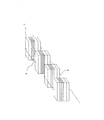
次に、図6を参照して、磁気抵抗効果素子1における材料を含んだ具体的な積層構造について説明する。図6は、本発明の実施の形態1における磁気抵抗効果素子の材料に関する積層構造を示す概略図である。自由層(強磁性層)8は、Co−Fe−B(コバルト−鉄−ホウ素)合金膜からなっている。Co−Fe−B合金膜は、トンネル絶縁層9がMgO膜である場合には、界面近傍において垂直の磁気異方性(膜面内の異方性エネルギーを正と定義した場合、負)を示す。
Next, with reference to FIG. 6, the specific laminated structure containing the material in the
なお、自由層8は、Co−Fe−B合金膜に限定されず、Fe(鉄)を主成分として含有する強磁性膜であればよく、これらを積層した強磁性膜であっても同様な効果を得ることが可能である。
The
Co−Fe−B合金膜からなる自由層8の厚さは、1.1nmである。なお、自由層8の厚さは、これに限定されず、素子の磁界応答性に応じて変更され得るものである。また、Co−Fe−B合金膜は、不可避不純物を含んでいる。
The thickness of the
トンネル絶縁層9は、MgO(酸化マグネシウム)膜からなっている。なお、トンネル絶縁層9は、これに限定されず、Mg(マグネシウム)と酸素を含有していればよく、MgAl2O4(スピネル)等であってもよい。The
MgO膜からなるトンネル絶縁(膜)層9の厚さは、1.7nmである。なお、トンネル絶縁層9の厚さは、これに限定されず、後述するキャップ層12よりも厚い必要があるが、素子の抵抗や磁界応答性に応じて変更され得るものである。また、MgO膜は、不可避不純物を含んでいる。
The thickness of the tunnel insulating (film)
強磁性層10aは、Co−Fe−B合金膜からなっている。なお、強磁性層10aは、Co−Fe−B合金膜に限定されず、Fe(鉄)、Co(コバルト)等のCo(コバルト)、Ni(ニッケル)およびFe(鉄)の少なくともいずれかを主成分とする強磁性膜であればよく、これらを積層した強磁性膜であっても同様な効果を得ることが可能である。
The
Co−Fe−B合金膜からなる強磁性層10aの厚さは、1.5nmである。なお、強磁性層10aの厚さは、これに限定されず、素子の磁界応答性に応じて変更され得るものである。また、Co−Fe−B合金膜は、不可避不純物を含んでいる。
The
非磁性層10cは、Ru(ルテニウム)膜からなっている。なお、非磁性層10cは、Ru膜に限定されず、Rt、Rb等の主に白金族からなる遷移金属の非磁性膜であればよく、同様な効果を得ることが可能である。
The
Ru膜からなる非磁性層10cの厚さは、0.8nmである。なお、非磁性層10cの厚さは、これに限定されず、素子の磁界応答性に応じて変更され得るものである。また、Ru膜は不可避不純物を含んでいる。
The thickness of the
強磁性層10bは、Co−Fe合金膜からなっている。なお、強磁性層10bは、Co−Fe合金膜に限定されず、Fe(鉄)、Co(コバルト)等のCo(コバルト)、Ni(ニッケル)およびFe(鉄)の少なくともいずれかを主成分とする強磁性膜であればよく、これらを積層した強磁性膜であっても同様な効果を得ることが可能である。
The
Co−Fe合金膜からなる強磁性層10bの厚さは、1.5nmである。なお、強磁性層10bの厚さは、これに限定されず、素子の抵抗や磁界応答性に応じて変更され得るものである。また、Co−Fe合金膜は、不可避不純物を含んでいる。
The thickness of the
反強磁性層10dは、Ir−Mn(イリジウム−マンガン)合金膜からなっている。なお、反強磁性層10dは、Ir−Mn合金膜に限定されず、Pt−Mn(白金−マンガン)合金、Fe−Mn(鉄−マンガン)合金、Ni−Mn(ニッケル−マンガン)合金等の反強磁性膜であればよく、同様な効果を得ることが可能である。
The
Ir−Mn膜からなる反強磁性層10dの厚さは、20nmである。なお、反強磁性層10dの厚さは、これに限定されず、素子の抵抗や磁界応答性に応じて変更され得るものである。また、Ir−Mn合金膜は、不可避不純物を含んでいる。
The
下部電極層6および上部電極層7は、各々、Ta(タンタル)膜からなっている。なお、下部電極層6および上部電極層7は、各々、例えば、Ru膜等の他の金属であってもよく、これに限定されない。下部電極層6が図1に示す配線5に接続され、上部電極層7が図1に示す配線4に接続されている。配線4、5には、各々、Cu(銅)が用いられている。なお、配線4、5は、例えば、Al(アルミニウム)など、他の金属であってもよく、各々、これに限定されない。
The
キャップ層12は、自由層8との界面を有するように設置されており、MgO(酸化マグネシウム)膜からなっている。なお、キャップ層12は、これに限定されず、Mg(マグネシウム)と酸素を含有していればよく、MgAl2O4(スピネル)等であってもよい。The
MgO膜からなるキャップ層12の厚さは、1.0nmである。ここで、MgO膜の厚さに依存した抵抗は、概ね、0.3nmで一桁変化する。
The
ここでは、MgO膜からなるキャップ層12の厚さは、トンネル絶縁層9のMgO膜よりも0.7nm薄いことから、キャップ層12のMgO膜に起因する抵抗は、トンネル絶縁層9に起因する抵抗よりも2桁以上小さく、検出される抵抗変化率への影響は、十分に小さい。また、0.8nmより薄いMgO膜では、膜が不連続となる場合や十分な結晶性が得られない場合があるが、ここでのキャップ層12のMgO膜は、これよりも厚く、十分な効果が得られる。なお、キャップ層12の厚さは、これに限定されず、トンネル絶縁層9よりも薄い必要はあるが、素子の抵抗や磁界応答性に応じて変更され得るものである。また、MgO膜は、不可避不純物を含んでいる。
Here, since the thickness of the
以上のように、本実施の形態1の磁気抵抗効果素子1では、自由層となる強磁性層8の磁化81は、膜面の垂直方向の成分も有している。これにより、外部磁界Hexが印加された場合には、膜の垂直方向の磁化成分も有した状態で磁化の回転が発生する。ここでは、固着層10の磁化は、膜の面内方向であるが、垂直成分を含んでいてもよい。
As described above, in the
そして、本実施の形態1の磁気抵抗効果素子1の強磁性層8の磁化81の配置によれば、図3に示したように、外部から磁界Hexが印加された場合、磁化81が回転することにより、トンネル絶縁層9を介した電子のトンネル確率が変化する。この結果、外部磁界Hexに依存して抵抗が変化する。
And according to arrangement | positioning of the
次に、本実施の形態1の磁気抵抗効果素子および磁界検出器の製造方法について説明する。磁気抵抗効果素子1を構成するそれぞれの金属膜(図3参照)は、基板11上にDC(直流)マグネトロンスパッタリングにより形成される。基板11は、Si(ケイ素)、SiC(炭化ケイ素)、GaN(窒化ガリウム)、GaAs(ヒ化ガリウム)、ガラスなどにより形成される。なお、基板11は、これに限定されず、その他の材料であってもよく、磁気抵抗効果素子1の下に、配線やトランジスタ、ダイオード等の電子回路が形成されていてもよい。
Next, a method for manufacturing the magnetoresistive effect element and the magnetic field detector according to the first embodiment will be described. Each metal film (see FIG. 3) constituting the
DCマグネトロンスパッタリングを用いて、Ta膜が下部電極層6として形成される。下部電極層6としてのTa膜が形成された後、大気に曝されることなく、同一装置内で膜厚20nmのIr−Mn合金膜が反強磁性層10dとして形成される。引続き、大気に曝すことなく、強磁性層10bとしての膜厚1.5nmのCo−Fe合金膜、非磁性層10cとしての膜厚0.8nmのRu膜、強磁性層10aとしての膜厚1.5nmのCo−Fe−B合金膜が、順次形成される。
A Ta film is formed as the
引続き、大気に曝すことなく、RF(高周波)マグネトロンスパッタリングを用いて膜厚1.7nmのMgO膜がトンネル絶縁層9として形成された後に、DCマグネトロンスパッタリングを用いて自由層(強磁性膜)8としての膜厚1.1nmのCo−Fe−B合金膜が形成される。その後に、1.0nmのキャップ層12のMgO膜が形成され、Ta膜が上部電極層7として形成される。
Subsequently, after the MgO film having a thickness of 1.7 nm is formed as the
なお、これらの膜を形成する際は、膜面方向に100Oeの磁界が印加される。これによって固着層10を構成するIr−Mn膜とCo−Fe膜、およびCo−Fe−B膜に磁気異方性が付与される。磁気抵抗効果素子1を構成する下部電極層6から上部電極層7までの膜は、全て同一装置内で形成される。トンネル絶縁層9およびキャップ層12であるMgO膜については、DCマグネトロンスパッタリングによりMg(マグネシウム)膜を形成した後に、酸素を含む酸化雰囲気に曝すことで形成してもよい。
When these films are formed, a magnetic field of 100 Oe is applied in the film surface direction. Thereby, magnetic anisotropy is imparted to the Ir—Mn film, the Co—Fe film, and the Co—Fe—B film constituting the pinned
その後に熱処理が実施される。目的は、MgO膜とそれを挟む2層のCo−Fe−B膜の結晶化を促進するとともに、固着層10の膜に磁気異方性を付与するためである。ここでは、固着層10のCo−Fe−B膜とCo−Fe膜の磁化を飽和するための磁界である15kOeが印加される。磁界印加方向は、磁気抵抗効果素子1の成膜時と同様であり、後述する磁気抵抗効果素子1の短手方向である。
Thereafter, heat treatment is performed. The purpose is to promote crystallization of the MgO film and the two Co-Fe-B films sandwiching it, and to impart magnetic anisotropy to the pinned
磁気抵抗効果素子1の熱処理温度は、Co−Fe−B膜の結晶化が可能であり、かつ固着層のIr−Mn膜とCo−Fe膜との間の交換結合が実質的になくなる、300℃としている。この温度で、1時間保持された。
The heat treatment temperature of the
上記の熱処理を経た後、固着層10の強磁性膜10aと10bの磁化は、それぞれ180°の方向を向く。つまり、非磁性層10cであるRu膜を挟んで対向するCo−Fe合金膜の磁化101bと、Co−Fe−B合金膜の磁化101aは、互いに反対方向を向く。なお、強磁性層(自由層)8の磁化81は、材料の結晶構造に依存した膜の垂直方向の磁気異方性を含むことで、熱処理時の磁界印加による磁化方向81への影響は、小さい。
After the above heat treatment, the magnetizations of the
この後、フォトリソグラフィにより所望のパターンが形成される。積層化された磁気抵抗効果素子1を構成する膜が形成された後、フォトレジストにより所望のパターンが形成される。その後、フォトレジストにより形成された所望のパターンをマスクとして、反応性イオンエッチングにより磁気抵抗効果素子1を電気的および磁気的に分離することで、磁気抵抗効果素子1の形状が得られる。
Thereafter, a desired pattern is formed by photolithography. After the film constituting the laminated
本実施の形態1における磁気抵抗効果素子1は、前述したように長方形であり、たとえば、短辺×長辺が200nm×600nmの長方形状に形成される。磁気抵抗効果素子1の長手方向は、積層膜における固着層10の形成時の磁界印加方向と直交する方向である。
The
上記のパターン形成により、自由層となる強磁性層8であるCo−Fe−B膜の磁化81は、形状による反磁界の影響を受け、その磁化81は、形状の長手方向の成分を有することとなる。すなわち、強磁性層8の磁化81は、結晶構造に依存した磁気異方性による膜面の垂直成分と、形状磁気異方性による形状の長手方向の成分とを有している。
Due to the above pattern formation, the
なお、先の図1に示すように、配線4、5を、それぞれ下部電極層6および上部電極層7に接続することで、磁気抵抗効果素子1と直流電源2および電圧計3とは、電気的に接続される。ここでは、接続方法の詳細な説明は省略するが、このような接続を行うことにより、本実施の形態1の磁気抵抗効果素子1を用いた磁界検出器100が形成される。
As shown in FIG. 1, the
次に、本実施の形態1の磁界検出器の磁界検出動作について説明する。先の図1に示したように、磁界検出時には、磁気抵抗効果素子1に配線4、5を通じて直流電源2から一定電流Iが供給される。磁気抵抗効果素子1に対して外部から磁界Hexが印加されると、外部からの磁界Hexの印加方向に応じて、磁気抵抗効果素子1の抵抗値が変化する。
Next, the magnetic field detection operation of the magnetic field detector according to the first embodiment will be described. As shown in FIG. 1 above, at the time of magnetic field detection, a constant current I is supplied from the
この外部からの磁界Hexの印加方向に応じた磁気抵抗効果素子1の抵抗値の変化により、直流(電流)電源2から供給される一定電流Iに対して、磁気抵抗効果素子1の下部電極層6と上部電極層7との間の電圧が変化する。この電圧変化が電圧計3で検出されて、外部からの磁界Hexが検出される。
The lower electrode layer of the
なお、ここでは図示しないが、磁気抵抗効果素子1の抵抗変化を検出することで外部磁界Hexを検出していることから、直流(電圧)電源2により一定電圧を磁気抵抗効果素子1に印加し、その際の電流値を電流計で検出することでも検出が可能である。
Although not shown here, since the external magnetic field Hex is detected by detecting the resistance change of the
また、磁気検出器に上述の電圧計3で検出された電圧値または上記電流計で検出された電流値をそれぞれあらかじめ設定された換算式に基づいて磁界強度に変換する演算部(図示省略)を設けてもよい。
In addition, the magnetic detector has a calculation unit (not shown) that converts the voltage value detected by the
続いて、先の図1に示すように磁気抵抗効果素子1の短手方向(長手方向に交差する方向)に対して外部から磁界Hexが印加された場合の磁気抵抗効果素子1の動作について説明する。
Next, the operation of the
図7は、本発明の実施の形態1における磁気抵抗効果素子の磁化方向を説明するための図である。より具体的には、図7(a)は、先の図1の磁気抵抗効果素子1の上面図、図7(b)(c)は、図7(a)のそれぞれ二重矢印(b)(c)の方向から見た断面図である。
FIG. 7 is a diagram for explaining the magnetization direction of the magnetoresistive effect element according to the first embodiment of the present invention. More specifically, FIG. 7A is a top view of the
図7中の矢印方向に外部から磁界Hexが印加されると、強磁性層8の無磁界における磁化81は、磁界Hex方向に回転する。この結果、固着層10の強磁性層10aの磁化101aとの相対角が変化する。
When a magnetic field Hex is applied from the outside in the direction of the arrow in FIG. 7, the
ここで、先の図3を参照して、TMR素子を用いた磁界方向の検出方法について説明する。TMR素子を構成するトンネル絶縁層9を介して対向する2層の強磁性層8、10aの磁化81、101aの向きを、それぞれ、θ1、θ2とすると、素子抵抗Rは、近似的に下式(1)で表される。
R=R0−ΔR/2・cos(θ2−θ1) (1)Here, with reference to FIG. 3, the detection method of the magnetic field direction using the TMR element will be described. When the directions of the
R = R0−ΔR / 2 · cos (θ2−θ1) (1)
上式(1)において、R0は、素子抵抗の中心値であり、ΔRは、素子の抵抗変化量である。TMR素子の自由層の強磁性層8の磁化は、外部磁界の大きさと向きに依存して方向が変化する。この結果、上式(1)において、θ1−θ2は、外部磁界に依存して変化する。従って、素子抵抗Rを測定することにより、磁界が検出される。
In the above formula (1), R0 is the center value of the element resistance, and ΔR is the resistance change amount of the element. The direction of magnetization of the
再び、図7を参照して、本実施の形態1の磁気抵抗効果素子1では、図7中の矢印方向に外部から磁界Hexが印加されることにより、強磁性層(自由層)8の磁化81は、外部からの磁界Hexの方向へ回転する。すなわち、強磁性層8の磁化81は、磁界Hexの方向へ回転して、磁化82に変化する。したがって、強磁性層8、強磁性層10aの相対的な磁化方向が変化する。そのため、先の図3に示すトンネル絶縁層9を通じた電子のトンネル確率も変化する。これによって、外部からの磁界Hexに依存した素子抵抗Rの変化が得られる。
Again referring to FIG. 7, in
なお、外部からの磁界Hexをさらに大きくすると、磁化82が外部からの磁界Hexの印加方向へと飽和するため、素子抵抗Rは、最大値で飽和する。外部からの磁界Hexと素子抵抗Rとの関係を用いて、磁気抵抗効果素子1の積層方向(膜面に垂直方向)に一定の電流Iを流し、先の図1に示す電圧計3により磁気抵抗効果素子1にかかる電圧Vを測定することで、外部からの磁界Hexの強度が検出される。
If the external magnetic field Hex is further increased, the
次に、本実施の形態1における磁気抵抗効果素子の作用効果について説明する。[発明が解決しようとする課題]において説明したように、従来のスピンバルブ型の磁気抵抗効果素子の構造においては、自由層として、膜面方向に磁化する自由層が用いられている。特に、磁気抵抗効果素子に積層膜を形成した後の熱処理の際に、固着層と自由層の強磁性膜の磁気異方性が実質的に同方向になる。このことから、自由層の磁気異方性の不足に起因し、自由層内で磁壁が存在する場合、あるいは磁化の回転中に安定的な状態が発生する場合があり、結果的にヒステリシスが発生する問題があった。なお、固着層と自由層の強磁性膜の磁気異方性が実質的に同方向になる場合でも、固着層に対し、垂直方向の磁界強度を検出することは可能である。しかしながら、磁界方向の検出は、不可能である。θ2−θ1は、0°(素子は最小の抵抗を示す)若しくは180°(素子は最大の抵抗を示す)を基準に±90°の変化となるためである。この場合は、磁気抵抗効果素子が示す最大の抵抗変化に対し、1/2の変化のみとなる。
Next, the effect of the magnetoresistive effect element in this
これによって、自由層磁化の履歴に依存して、磁界検出器としての出力信号に誤差が発生し、その結果、磁界検出誤差が発生していた。対策として、自由層の磁気異方性を付与するための磁気的に硬質な強磁性体層の設置、あるいは磁界の印加機構などが考えられる。しかしながら、これらの対策の場合には、製造工程が複雑となり、例えば、複数の素子を集積回路に搭載する場合などに、集積化が困難となる課題があった。 As a result, an error occurs in the output signal as the magnetic field detector depending on the history of the free layer magnetization, and as a result, a magnetic field detection error occurs. Possible countermeasures include the installation of a magnetically hard ferromagnetic layer for imparting magnetic anisotropy of the free layer, or a magnetic field application mechanism. However, in the case of these measures, the manufacturing process becomes complicated, and there is a problem that integration is difficult when, for example, a plurality of elements are mounted on an integrated circuit.
これに対して、本実施の形態1の磁気抵抗効果素子1は、自由層8とトンネル絶縁層9の界面において、自由層8の磁化は、垂直方向の磁気異方性を有する。これによって前述したヒステリシスの発生を素子単体で抑制することが可能であり、高精度化が可能である。
On the other hand, in the
ここで、本発明における効果を説明するため、従来の積層構造との比較を行う。図8は、従来の磁気抵抗効果素子の積層構造を示す図である。図8に示す従来の磁気抵抗効果素子の積層構造においては、図6に示した本発明の磁気抵抗効果素子1の積層構造と異なり、キャップ層12であるMgO膜がなく、上部電極層7がキャップ層12の役割を兼ねている。
Here, in order to explain the effect of the present invention, a comparison with a conventional laminated structure is performed. FIG. 8 is a diagram showing a laminated structure of a conventional magnetoresistive effect element. In the laminated structure of the conventional magnetoresistive element shown in FIG. 8, unlike the laminated structure of the
図9は、従来の磁気抵抗効果素子の自由層8の磁化方向を説明するための図であり、本実施の形態1における磁化方向を示した先の図4と同様な断面を示している。
FIG. 9 is a diagram for explaining the magnetization direction of the
図8に示した従来の構造においては、自由層8がMgO膜と有する界面は、トンネル絶縁層9との界面のみである。このため、自由層8の界面における垂直磁気異方性は、一方の界面のみで発現されている。
In the conventional structure shown in FIG. 8, the interface that the
図10は、本発明の実施の形態1における磁気抵抗効果素子1と、従来の磁気抵抗効果素子のそれぞれのヒステリシスの幅と抵抗変化率における、自由層の厚さ依存性を示した比較図である。図10においては、ヒステリシスの幅を▲で示し、抵抗変化率を●で示している。
FIG. 10 is a comparison diagram showing the dependence of the hysteresis width and resistance change rate of the
この図10に示したように、自由層8の厚さに依存したヒステリシスの幅は、従来の素子では1.4nm以下で概ね0となっているのに対して、本実施の形態1の素子では、1.2nm以下で概ね0となることが分かる。さらに、抵抗変化率も、ヒステリシスの幅と同様な傾向で変化している。
As shown in FIG. 10, the width of the hysteresis depending on the thickness of the
ここで、従来の素子においては、ヒステリシスの幅は、1.4nm以上では急激に増大していることから、ヒステリシスを抑制して動作するためには、自由層を1.4nm以下の厚さとする必要がある。しかしながら、抵抗変化率は、1.4nm以下で急激に減少する。ここで、磁界検出における感度は、抵抗変化率に依存する。 Here, in the conventional device, the width of the hysteresis increases rapidly at 1.4 nm or more. Therefore, in order to operate with the hysteresis suppressed, the free layer has a thickness of 1.4 nm or less. There is a need. However, the rate of change in resistance decreases sharply below 1.4 nm. Here, the sensitivity in magnetic field detection depends on the resistance change rate.
このことから、従来の素子においては、磁界検出の感度が自由層の厚さに大きく依存する。自由層8の厚さが1.4nmでの抵抗変化率を100%とした場合、0.015nm(厚さに対して1%)の厚さの変動により、10%の抵抗変化率が減少する。これによって、製造工程において、基板面内で自由層の厚さに分布が発生した場合、あるいは基板間で同様な分布が発生した場合には、磁気抵抗効果素子の感度が大きく変化することとなる。自由層8の厚さが1.4nmである場合を基準とすると、抵抗変化率の変動を10%以内とするためには、自由層8の設定する厚さに対して、1%以内の範囲で制御する必要がある。この制御は、実質的に困難である。
For this reason, in the conventional element, the sensitivity of the magnetic field detection greatly depends on the thickness of the free layer. When the rate of change in resistance when the thickness of the
これに対して、本実施の形態1の磁気抵抗効果素子1では、ヒステリシスの幅は、1.2nm以下でほぼ0となるが、それより薄い自由層においても、抵抗変化率の急激で不連続な変化はないことが分かる。すなわち、従来の素子と比較し、自由層の厚さに対して感度が安定となることが分かる。抵抗変化率の変動を10%以内とするためには、自由層8の設定する厚さに対する誤差は、3%まで許容される。
On the other hand, in the
これは、本発明の磁気抵抗効果素子1の自由層8が、トンネル絶縁層9との界面で垂直磁気異方性を有しており、かつトンネル絶縁層9との反対側の界面においても垂直磁気異方性を有していることにより、図8で示した従来の構造よりも、垂直磁気異方性成分が安定化したことによるものである。
This is because the
なお、図10において、従来の素子と比較して、ヒステリシスの幅が0となる厚さが異なる原因は、自由層8上の界面における磁化の損失の差異によるものである。
In FIG. 10, the reason why the thickness at which the hysteresis width becomes 0 is different from that in the conventional element is due to the difference in magnetization loss at the interface on the
以上のように、実施の形態1によれば、自由層となる強磁性層は、垂直方向の磁化成分を有しており、かつ自由層の形状に依存した反磁界の影響により、素子上面からの投影面でみた場合には、素子の長手方向に磁化している。通常の膜面内に磁化した自由層では、長手方向の端部において磁化を緩和するために、自由層の面内において局所的な磁化の配置をとり、ヒステリシスが発生する要因となっていた。 As described above, according to the first embodiment, the ferromagnetic layer serving as the free layer has a magnetization component in the vertical direction, and from the upper surface of the element due to the influence of the demagnetizing field depending on the shape of the free layer. When viewed on the projection plane, the magnet is magnetized in the longitudinal direction of the element. In the free layer magnetized in the normal film plane, in order to relax the magnetization at the end portion in the longitudinal direction, the local magnetization is arranged in the plane of the free layer, which causes a hysteresis.
これに対して、本発明での自由層は、垂直方向に磁化が向きやすく、長手方向の端部での磁化の緩和が可能となる。その結果として、外部磁界が印加された際に、特に低磁界において磁化が回転する際のヒステリシスの発生を抑制することが可能である。すなわち、その際の自由層の厚さに依存した特性の変化を緩和することが可能であり、追加の構造を増やすことなく、高精度で高集積化が可能な磁界検出器を実現することができる。 On the other hand, the free layer in the present invention is easily magnetized in the vertical direction, and can relax the magnetization at the end in the longitudinal direction. As a result, when an external magnetic field is applied, it is possible to suppress the occurrence of hysteresis especially when the magnetization rotates in a low magnetic field. That is, it is possible to alleviate the change in characteristics depending on the thickness of the free layer at that time, and to realize a magnetic field detector capable of high accuracy and high integration without increasing the number of additional structures. it can.
まとめると、本願発明における自由層は、面内磁化成分とともに、上下界面において垂直方向の磁化成分を有し、これによって、高感度でかつヒステリシスを抑制した磁界応答を実現する。さらに、トンネル絶縁膜であるMgO膜に加え、キャップ層もMgO膜としたことで、自由層の厚さに依存した特性の急激な変動を抑制することが可能となる。この結果、磁界応答性の制御性が向上し、製造工程に起因した特性の変動を抑制することが可能となる。 In summary, the free layer in the present invention has a magnetization component in the vertical direction at the upper and lower interfaces along with the in-plane magnetization component, thereby realizing a magnetic field response with high sensitivity and suppressed hysteresis. Furthermore, in addition to the MgO film which is a tunnel insulating film, the cap layer is also an MgO film, so that it is possible to suppress rapid fluctuations in characteristics depending on the thickness of the free layer. As a result, the controllability of the magnetic field responsiveness is improved, and it is possible to suppress fluctuations in characteristics due to the manufacturing process.
さらに、キャップ層を構成するMgを含有する酸化物の厚さが、Mgを含有する酸化物からなるトンネル絶縁層の厚さよりも薄い構造となっている。この結果、MgO膜を追加したこと(素子に直列抵抗が加わったこと)による抵抗の増大および抵抗変化率の減少を抑制することができる。 Furthermore, the thickness of the oxide containing Mg constituting the cap layer is thinner than the thickness of the tunnel insulating layer made of the oxide containing Mg. As a result, it is possible to suppress an increase in resistance and a decrease in the resistance change rate due to the addition of the MgO film (addition of series resistance to the element).
実施の形態2.
本実施の形態2では、磁気抵抗効果素子1の積層構造の変形例について説明する。図11〜図14は、本発明の実施の形態2における磁気抵抗効果素子の積層構造変形例1〜4を示す概略図である。
In the second embodiment, a modified example of the laminated structure of the
積層構造変形例1に相当する図11の磁気抵抗効果素子1は、自由層8が2層の強磁性層8a、8bの積層構造で構成されている。具体的には、強磁性膜8aは、Co−Fe−B合金膜であり、強磁性膜8bは、Fe−B合金である。なお、自由層8は、2層に限定されることはなく、組成が異なる2層以上の強磁性膜とすることができる。
The
ここで、先の実施の形態1における図6の構造でも自由層8として適用されているCo−Fe−B合金は、TMR素子において大きな抵抗変化率が得られる材料として知られている。このことから、図11の磁気抵抗効果素子においても、図6と同様な抵抗変化率が得られる。
Here, the Co—Fe—B alloy applied as the
そして、図11に示す構造は、Co−Fe−B合金膜の上層にFe−B膜をさらに有している。Co−Fe−B合金膜とMgO膜との界面における垂直磁気異方性は、Fe(鉄)とO(酸素)の相互作用によって得られると考えられる。Fe−B膜では、Fe含有率がCo−Fe−B合金膜よりも高く、Fe−B膜8bとキャップ層のMgO膜12の界面においては、Co−Fe−B膜よりも強固な垂直軸異方性が得られる。
The structure shown in FIG. 11 further includes an Fe—B film on the Co—Fe—B alloy film. It is considered that the perpendicular magnetic anisotropy at the interface between the Co—Fe—B alloy film and the MgO film is obtained by the interaction of Fe (iron) and O (oxygen). In the Fe—B film, the Fe content is higher than that in the Co—Fe—B alloy film, and the vertical axis is stronger at the interface between the Fe—
これらによって、図11の構造により、図6で説明した構造と同等な抵抗変化率と、より安定した垂直磁気異方性が得られる。なお、ここでは、強磁性膜8bとしては、Fe−B膜を示したが、強磁性膜8aのCo−Fe−B合金膜よりもFe含有率が大きければ同様な効果が得られ、Fe−B膜に限定されるものではない。
Accordingly, the resistance change rate equivalent to the structure described in FIG. 6 and more stable perpendicular magnetic anisotropy can be obtained by the structure of FIG. Although the Fe—B film is shown here as the
このように、積層構造変形例1では、自由層を組成が異なる2層以上の強磁性膜により構成し、トンネル絶縁層と接する強磁性膜のFe含有率が、キャップ層と接する強磁性膜のFe含有率よりも小さいような構成としている。この結果、Fe組成比が大きく垂直磁気異方性が大きく得られる材料を、トンネル絶縁層から離し、抵抗変化率が大きく得られる材料をトンネル絶縁層側に設けることができ、抵抗変化率を損ねることなく、磁界応答性を調整することが可能となる。
Thus, in the
次に、積層構造変形例2に相当する図12に示した磁気抵抗効果素子1は、図6に示した構造に加え、キャップ層12上にCo−Fe−B合金膜からなる強磁性膜13をさらに備えている。自由層8と強磁性膜13は、キャップ層12のMgO膜を介して対向している。この構造においては、強磁性膜13とキャップ層12の界面においても垂直方向の磁気異方性が得られる。
Next, in addition to the structure shown in FIG. 6, the
この強磁性膜13は、自由層8とキャップ層12を介して静磁的に結合することから、自由層8とキャップ層12における界面の垂直磁気異方性の安定化に作用する。すなわち、強磁性膜13を有することで、自由層8における垂直磁気異方性成分を安定化することが可能となる。
Since the
次に、積層構造変形例3に相当する図13は、図12で示した強磁性膜13をCo−Pt積層膜とした磁気抵抗効果素子1を示している。Co−Pt積層膜は、Co膜とPt膜を繰り返し積層した構造であり、MgO膜との界面以外でも垂直磁気異方性を示す。この構造においても、図12での説明と同様に、強磁性膜13は、自由層8とキャップ層12を介して静磁的に結合する。この結果、自由層8とキャップ層12における界面の垂直磁気異方性の安定化に作用する。すなわち、Co−Pt積層膜による強磁性膜13を有することによっても、自由層8における垂直磁気異方性成分を安定化することが可能となる。
Next, FIG. 13 corresponding to the
なお、強磁性層13は、Co(コバルト)、Fe(鉄)、Ni(ニッケル)、およびTb(テルビウム)等のライタノイド元素、の少なくともいずれかを主成分とする強磁性膜、もしくはPt(白金)およびPd(パラジウム)を含有またはこれらとの界面を有する強磁性膜で、かつ膜面の垂直方向に磁気異方性を有する材料であればよい。
The
次に、積層構造変形例4に相当する図14は、図13に示す構造において、強磁性膜13下のキャップ層にTa膜12bを付与し、結果として、2層のキャップ層12a、12bを備えている。このようにキャップ膜のMgO膜12a上に別の材料の膜12bを挿入することで、強磁性膜13を成長する際の下地を任意に選択することも可能となる。
Next, FIG. 14 corresponding to the
このように、積層構造変形例2〜4では、キャップ層12と、自由層8と反対側で接し、垂直方向に磁化した成分を有する強磁性膜13をさらに備えている。この結果、強磁性膜13は、トンネル絶縁層9と反対側からキャップ層12に静磁的に結合することにより、自由層8が垂直方向に磁化することを補助する。これによって、自由層8の垂直方向の磁化が安定化する。
As described above, in the laminated structure modification examples 2 to 4, the
以上のように、実施の形態2によれば、先の実施の形態1における積層構造の変形例を用いることで、垂直磁気異方性成分の安定化、あるいは強磁性膜を成長する際の下地の選択自由度の拡張を図ることができる。 As described above, according to the second embodiment, by using a modified example of the laminated structure in the first embodiment, it is possible to stabilize the perpendicular magnetic anisotropy component or to provide a base for growing a ferromagnetic film. The degree of freedom of selection can be expanded.
実施の形態3.
本実施の形態3では、複数個の磁気抵抗効果素子1を、配線4、5を用いて直列もしくは並列に接続する具体例について説明する。図15〜図18は、本発明の実施の形態3における磁気抵抗効果素子の接続変形例1〜4を示す概略図である。
In the third embodiment, a specific example in which a plurality of
動作原理は、前述と同様である。本実施の形態3のように、複数個の磁気抵抗効果素子1を直列あるいは並列に接続した構成を用いる場合には、出力信号が複数の素子で平均化されるため、個別の素子における抵抗や磁界応答性等の特性ばらつきを平均化することが可能である。
The operation principle is the same as described above. When using a configuration in which a plurality of
接続する磁気抵抗効果素子1の数は、抵抗やばらつきの平均化により調整することが可能であるが、直列接続の場合には、各素子抵抗の電圧依存性の対称性、および後述する読み出し電流による磁界発生の対称性を考慮し、偶数個であることが好ましい。
The number of
接続変形例1に相当する図15においては、磁気抵抗効果素子1の長手方向に沿った配置(複数の磁気抵抗効果素子1がそれぞれ隣り合う磁気抵抗効果素子の長手方向端部同士が向き合う方向に向けられて配置されて並べられている)で、複数の磁気抵抗効果素子1が直列接続されている。この場合には、後述する電流検出器、配線などの直線に沿って発生する局所的な磁界の検出が容易となる。
In FIG. 15 corresponding to the connection modification example 1, the arrangement along the longitudinal direction of the magnetoresistive effect element 1 (in the direction in which the longitudinal ends of the
また、接続変形例2に相当する図16の配置は、磁気抵抗効果素子1の短手方向に沿った配置(複数の磁気抵抗効果素子1がそれぞれ隣り合う磁気抵抗効果素子の短手方向端部同士が向き合う方向に向けられて配置されて並べられている)で、複数の磁気抵抗効果素子1が直列接続されている。この配置では、配線4および5を流れる読出し電流によって磁界が発生した場合、検出対象の磁界とは方向が異なる、磁気抵抗効果素子1の長手方向の磁界が印加される。この結果、読出し電流に起因した検出誤差を抑制することが可能となる。
Further, the arrangement of FIG. 16 corresponding to the connection modification example 2 is arranged along the short direction of the magnetoresistive effect element 1 (the end portions in the short direction of the magnetoresistive effect elements adjacent to each other by the plurality of magnetoresistive effect elements 1). A plurality of
なお、図15と図16の配置は、ともに配線4が磁気抵抗効果素子1の上部に位置し、配線5が下部に位置している。このため、磁気抵抗効果素子1の位置で、電流によって発生する磁界は、互いに逆向きである。これによって、読出し電流に起因した検出誤差を抑制することが可能である。
In both the arrangements of FIGS. 15 and 16, the
接続変形例3に相当する図17、および接続変形例4に相当する図18の接続は、それぞれ、磁気抵抗効果素子1の長手方向と短手方向に沿った配置で、並列接続されている。この場合の効果も、直列接続での配置と同様である。なお、直列接続にした場合には、1つの磁気抵抗効果素子1に加わる電圧を抑制することが可能であり、この結果、電圧に依存した抵抗変化率の減少を抑制することが可能であり、電圧に起因したトンネル絶縁層の破壊も防ぐことが可能である。
The connection of FIG. 17 corresponding to the
一方、並列接続した場合には、磁気抵抗効果素子1の数に反比例した低抵抗化が可能であり、前記の直列接続と組み合わせる場合など、用途や周辺回路に応じた抵抗の調整も可能である。
On the other hand, when connected in parallel, the resistance can be reduced in inverse proportion to the number of
以上のように、実施の形態3によれば、複数個の磁気抵抗効果素子1を直列あるいは並列に接続した構成を用いることで、素子間の特性のばらつきの影響を平均化することが可能であり、素子の特性の電流方向に対する非対称性の緩和、素子に印加される電圧の緩和も可能となる。この結果、複数個の磁気抵抗効果素子1を採用することで、磁界の検出誤差を抑制することが可能となる。
As described above, according to the third embodiment, by using a configuration in which a plurality of
実施の形態4.
先の実施の形態3においては、複数個の磁気抵抗効果素子1を直列あるいは並列に接続した接続変形例1〜4について説明した。これに対して、本実施の形態4においては、磁気抵抗効果素子1を複数個用いてブリッジ回路を構成する接続変形例5について説明する。
In the previous third embodiment,
図19は、本発明の実施の形態4における磁気抵抗効果素子の接続変形例5を示す概略図であり、本実施の形態4における磁界検出器の等価回路図に相当する。
FIG. 19 is a schematic diagram showing
図19における磁界検出器100は、直流電源2からの電流が供給されるブリッジ回路30と、ブリッジ回路30のノードN2およびノードN4の電圧を差動増幅する差動増幅器32と、この差動増幅器32の出力信号の電圧レベルを検出する電圧計3とを有している。磁界検出器100では、ブリッジ回路30から検出磁界に応じた信号が出力される。
A
ブリッジ回路30は、ノードN1とノードN2の間に接続される磁気抵抗効果素子1aと、ノードN2と接地ノードN3の間に接続される定抵抗素子31bと、ノードN1とノードN4の間に接続される定抵抗素子31aと、ノードN4と接地ノードN3の間に接続される磁気抵抗効果素子1bとを有している。ノードN1が、直流電源2に接続されている。ノードN2とN4が、差動増幅器32の相補入力にそれぞれ接続されている。接地ノードN3が、グランドに接続されている。
The
2つの磁気抵抗効果素子1a、1bは、先の実施の形態1で説明した図3に示す構成を有している。また、外部磁界の磁気抵抗効果素子1a、1bへの影響は、先の実施の形態1で説明した内容と同じである。また、定抵抗素子31aおよび31bは、抵抗値が同じである。直流電源2から、ノードN1へ一定の大きさの電流が供給される。磁気抵抗効果素子1a、1bでは、その抵抗値が、ほぼ同じ特性で変化する。この結果、ブリッジ回路30において2つの電流経路、すなわちノードN1→N2→N3の経路を流れる電流と、ノードN1→N4→N3を流れる電流の大きさは、同じとなる。
The two
外部磁界の影響により、磁気抵抗効果素子1a、1bの抵抗値が大きくなった場合、ノードN2の電圧が低下し、一方、ノードN4の電圧レベルが上昇する。逆に、外部磁界により磁気抵抗効果素子1a、1bの抵抗値が小さくなった場合、ノードN2の電圧レベルが上昇し、ノードN4の電圧レベルが低下する。
When the resistance values of the
したがって、ノードN2およびノードN4の電圧レベルは、磁気抵抗効果素子1a、1bの抵抗値変化に対して相補的に変化し、この差分値を、差動増幅器32で増幅する。これにより、1つの磁気抵抗効果素子による電圧変化と比較して、ノードN2およびノードN4の差分信号変化量が大きくなり、電圧計3により、外部磁界により生じる電圧変化を高精度で検出することができる。
Therefore, the voltage levels of the node N2 and the node N4 change complementarily to the resistance value change of the
このような構成を備えることで、大きな出力信号が得られる。また、無磁界において出力が0となる。さらに、磁気抵抗効果素子1a、1bの温度依存性を相殺することができるので、温度に依存した磁気抵抗効果素子1a、1bの抵抗変化を緩和することが可能である。
With such a configuration, a large output signal can be obtained. Further, the output becomes 0 in the absence of a magnetic field. Furthermore, since the temperature dependence of the
以上のように、実施の形態4によれば、複数個の磁気抵抗効果素子を用いてブリッジ回路を構成することで、差動での読み出しが可能となり、0点の確保が容易となる。この結果、磁界を高精度に検出できるとともに、温度に依存した磁気抵抗効果素子の抵抗変化を緩和することが可能となる。 As described above, according to the fourth embodiment, by configuring a bridge circuit using a plurality of magnetoresistive elements, differential reading is possible, and it is easy to secure 0 point. As a result, the magnetic field can be detected with high accuracy and the change in resistance of the magnetoresistive effect element depending on the temperature can be reduced.
実施の形態5.
先の実施の形態3においては、複数個の磁気抵抗効果素子1を直列あるいは並列に接続した接続変形例1〜4について説明した。また、先の実施の形態4においては、磁気抵抗効果素子1を複数個用いてブリッジ回路を構成する接続変形例5について説明した。これに対して、本実施の形態5では、形状の異なる複数の磁気抵抗効果素子が同一基板上に形成されている場合について説明する。
In the previous third embodiment,
図20は、本発明の実施の形態5における磁気抵抗効果素子の磁気特性の形状依存性を説明するための図である。図20を参照して、本実施の形態5における磁気抵抗効果素子1の積層構造を用いて、素子形状を変化させた場合の磁気特性を説明する。
FIG. 20 is a diagram for explaining the shape dependence of the magnetic characteristics of the magnetoresistive effect element according to the fifth embodiment of the present invention. With reference to FIG. 20, the magnetic characteristics when the element shape is changed using the laminated structure of the
図20(a)は、自由層である強磁性膜8の磁化が概ね飽和する異方性磁界について、短手方向の長さに対する長手方向の長さの比(形状アスペクト比)が一定の場合における短手方向の長さに対する依存性を示している。また、図20(b)は、短手方向の長さを一定として場合の形状アスペクト比の依存性を示している。
FIG. 20A shows a case where the ratio of the length in the longitudinal direction to the length in the short direction (shape aspect ratio) is constant for the anisotropic magnetic field in which the magnetization of the
抵抗変化率が一定である場合、異方性磁界は、磁気抵抗効果素子1の磁界に対する感度に反比例する。この結果からも明らかなように、これらの形状に依存して磁気抵抗効果素子1の感度が変化する。これを利用することで、膜構造は同一で、感度の異なる素子を同一平面に形成することが可能である。全ての素子を一括して形成することが可能であり、製造工程の増加もない。
When the rate of change in resistance is constant, the anisotropic magnetic field is inversely proportional to the sensitivity of the
なお、素子面積に依存する抵抗については、先の実施の形態3の接続変形例1〜4と組み合わせることで調整することが可能である。 The resistance depending on the element area can be adjusted by combining with the connection modification examples 1 to 4 of the third embodiment.
以上のように、実施の形態5によれば、形状に依存して感度が変化する磁気抵抗効果素子を、同一の膜構造として、同一平面に一括して形成することが可能となる。すなわち、感度や動作磁界が異なる複数の素子を、同一平面上に同時に形成することができる。 As described above, according to the fifth embodiment, it is possible to collectively form magnetoresistive elements whose sensitivity changes depending on the shape as the same film structure on the same plane. That is, a plurality of elements having different sensitivities and operating magnetic fields can be simultaneously formed on the same plane.
実施の形態6.
本実施の形態6では、先の実施の形態1で説明した磁気抵抗効果素子が、方向が決まった磁界(固着層の強磁性層10aにおける磁化101aに沿った方向)の検出に適しており、配線に対して位置を固定して用いる電流検出器に適することを、図面を用いて詳細に説明する。
In the sixth embodiment, the magnetoresistive effect element described in the first embodiment is suitable for detecting a magnetic field whose direction is determined (direction along the
図21は、本発明の実施の形態6における電流検出器を示す概略図である。図21における電流検出器102は、先の実施の形態1で説明した図3の積層構造を備えた磁界検出器100が用いられている。電流検出器102は、被測定物40である配線から一定の距離が保たれて配置されている。被測定物である配線40には、被測定用の電流iが流れている。
FIG. 21 is a schematic diagram showing a current detector according to the sixth embodiment of the present invention. As the
なお、図21においては、磁気抵抗効果素子1のみ図示されているが、電流検出器102は、先の実施の形態1に示された構成を全て備えている。また、電流検出器102は、図示しない出力信号検出回路も備えている。
In FIG. 21, only the
磁気抵抗効果素子1は、被測定用の電流iが流れる配線から発生する外部磁界Hexの方向と検出方向が一致するように配置されている。
The
次に、本実施の形態6の電流検出器における電流検出動作について説明する。被測定用の電流iが配線40に流れると、電流iの作用により、配線40と垂直な方向に環状磁界が発生する。この磁界Hexの大きさは、次式(2)で表される。
Hex=k・i/r (2)Next, the current detection operation in the current detector of the sixth embodiment will be described. When the current i to be measured flows through the
Hex = k · i / r (2)
上式(2)において、kは、比例定数であり、rは、配線40から磁気抵抗効果素子1までの距離である。磁気抵抗効果素子1と配線40との距離rを測定しておけば、比例定数kは、既知であるので、磁界Hexを測定することにより、電流iを測定することが可能である。なお、被測定物40である配線は、電流検出器102と同一基板上に配置されていてもよい。
In the above equation (2), k is a proportional constant, and r is the distance from the
本実施の形態6の電流検出器102は、磁気抵抗効果素子1により、磁界を帯びた被測定物40の磁界Hexを測定することで、被測定物40を流れる電流iを測定する。
The
出力信号検出回路すなわち演算部は、先の実施の形態1で記載した磁気検出器で検出された電流値または電圧値、または、さらにこれらを換算式で換算した磁界強度から、あらかじめ設定された換算式に基づいて、被測定物40の電流値iを求める機能を含む。
The output signal detection circuit, that is, the calculation unit, converts the current value or voltage value detected by the magnetic detector described in the first embodiment, or the magnetic field strength obtained by converting these values using a conversion formula, into a preset conversion. A function of obtaining the current value i of the
磁気抵抗効果素子1により、磁界Hexを帯びた被測定物40の磁界Hexを測定することで、被測定物40を流れる電流iを測定する。このため、電流検出において、誤差が少なく安定した出力信号が得られ、高精度な電流検出を行うことができる。また、電流検出器102の形成も容易である。
The current i flowing through the device under
また、図21においては、1個の磁気抵抗効果素子1からなる電流検出器102について説明したが、先の実施の形態3〜5で説明したような複数個の磁気抵抗効果素子1を用いる変形例を適用することも可能である。図22は、本発明の実施の形態6における電流検出器の磁気抵抗効果素子の接続を示す概略図である。具体的には、先の実施の形態3における図15に示した接続変形例1を用いた場合を示している。
In addition, in FIG. 21, the
配線40を流れる電流によって発生する磁界は、配線断面方向で観た場合、同心円の分布で説明される。このため、特に配線40と磁気抵抗効果素子1の距離が近い場合には、磁気抵抗効果素子1に不均一な磁界が印加されることとなる。これを抑制するためには、配線断面方向の磁気抵抗効果素子1の占有する長さを小さくすることが好ましく、このためには、図22に示したように、磁気抵抗効果素子1の長手方向に沿って接続する配置が好ましい。
The magnetic field generated by the current flowing through the
電流検出器102には、図22以外の数の磁気抵抗効果素子1が含まれていてもよく、これらの磁気抵抗効果素子1が、たとえば先の実施の形態4の図19に示したブリッジ回路30を形成していてもよい。また、先の実施の形態5で説明したように、感度の異なる磁気抵抗効果素子を同一面上に同時に形成することも可能である。これらの実施の形態3〜5は、適時組み合わせることができるものである。
The
以上のように、実施の形態6によれば、本発明の電流検出器を用いて、方向が決まった磁界を高精度に検出することができる。特に、被測定物である配線を流れる電流を測定するに当たって、配線に対して位置を固定して用いる用途に適している。 As described above, according to the sixth embodiment, a magnetic field whose direction is determined can be detected with high accuracy using the current detector of the present invention. In particular, when measuring the current flowing through the wiring that is the object to be measured, it is suitable for an application in which the position is fixed with respect to the wiring.
実施の形態7.
本実施の形態7では、本発明の磁気抵抗効果素子を備えた電流検出器を、半導体集積回路として構成する場合について説明する。本発明の実施の形態7で説明する半導体集積回路は、先の実施の形態1〜5の磁気抵抗効果素子を有しており、先の実施の形態6と同様な動作をする電流検出器を有している。電流検出器の動作原理も、先の実施の形態6と同様である。
In the seventh embodiment, a case where a current detector including the magnetoresistive effect element of the present invention is configured as a semiconductor integrated circuit will be described. The semiconductor integrated circuit described in the seventh embodiment of the present invention has the magnetoresistive effect element in the first to fifth embodiments, and includes a current detector that operates in the same manner as in the sixth embodiment. Have. The operation principle of the current detector is the same as that of the sixth embodiment.
図23は、本発明の実施の形態7における電流検出器を有する半導体集積回路の一部を示す概略断面図である。図23に示した電流検出器102は、先の実施の形態1の図3で示した磁気抵抗効果素子1が用いられている。電流検出器102は、被測定物40であるCu配線の直上に設置されている。この際の配線40と磁気抵抗効果素子1は、層間絶縁膜53によって絶縁されており、その距離は、層間絶縁膜53の厚さ、および磁気抵抗効果素子1の下に設置された下部電極50の厚さによって決定される。被測定物40である配線には、被測定用の電流iが流れている。
FIG. 23 is a schematic cross-sectional view showing a part of a semiconductor integrated circuit having a current detector according to
なお、図23においては、磁気抵抗効果素子1のみ図示されているが、電流検出器102は、先の実施の形態6に示した構成を全て備えている。また、電流検出器102は、図示しない出力信号検出回路も備えており、半導体集積回路に事前に形成されている。
Although only the
図23においては、他の構成として、複数の磁気抵抗効果素子1(図15等参照)、直流(電流、電圧)電源2(図1等参照)、電圧計3(図1等参照)、電流計(図示省略)、定抵抗素子31a、31b(図19等参照)、差動増幅器32(図19等参照)間を接続する配線4、5、プラグ51、層間絶縁膜52、53、54、55、56が示されている。動作方法については、先の実施の形態6と同様であるので、ここでの説明は省略する。
23, as other configurations, a plurality of magnetoresistive effect elements 1 (see FIG. 15 and the like), a direct current (current and voltage) power source 2 (see FIG. 1 and the like), a voltmeter 3 (see FIG. 1 and the like), a current Total wiring (not shown),
このような図23の構成を備えた半導体集積回路に含まれる磁気抵抗効果素子1で、磁界Hexを帯びた被測定物40(磁界Hexを発生する被測定物)の磁界Hexを測定することで、被測定物40を流れる電流iを測定する。このため、電流検出において誤差が少なく安定した出力信号が得られ、高精度な電流検出を行うことができる。また、電流検出器102の形成も容易である。
The
ここで、半導体集積回路を構成する際に、先の実施の形態4における図19で説明したブリッジ回路を形成し、定抵抗素子31a、31bにも磁気抵抗効果素子1a、1bと同一の素子を配置してもよい。図24は、本発明の実施の形態7における電流検出器を有する別の半導体集積回路の一部を示す概略断面図である。図24においては、磁気抵抗効果素子1a、1bのみ配線40の直上に設置し、定抵抗素子31a、31bに代わる磁気抵抗効果素子1c、1dを、配線40の直上以外に設置している。これにより、それぞれの出力信号の差分を得ることで、温度や周辺環境の磁界によるバックグラウンドの信号を差し引くことが可能である。
Here, when configuring the semiconductor integrated circuit, the bridge circuit described in FIG. 19 in the fourth embodiment is formed, and the
なお、磁気抵抗効果素子1c、1dは、定抵抗素子31a、31bのままとしてもよい。これにより、例えば、周辺機器が発する磁界の影響を差し引くことが可能であり、周辺環境の磁界の影響を抑制するための磁気シールドが不要となる。
The magnetoresistive effect elements 1c and 1d may be left as the
以上のように、実施の形態7によれば、先の実施の形態1〜6で説明した効果を利用し、半導体集積回路の配線を用いた電流検出が可能となる。本発明の磁界検出器および電流検出器を半導体集積回路として構成した場合、磁気抵抗効果素子と被測定物との距離は、層間絶縁膜によって決定される。このため、磁気抵抗効果素子と被測定物との距離を小さくすることが可能であり、結果として、高感度な検出が可能となる。さらに、被測定物から離れた素子を用いることで、バックグラウンドの磁界の影響を抑制することも可能となる。 As described above, according to the seventh embodiment, it is possible to detect the current using the wiring of the semiconductor integrated circuit using the effects described in the first to sixth embodiments. When the magnetic field detector and current detector of the present invention are configured as a semiconductor integrated circuit, the distance between the magnetoresistive effect element and the device under test is determined by the interlayer insulating film. For this reason, the distance between the magnetoresistive element and the object to be measured can be reduced, and as a result, highly sensitive detection is possible. Furthermore, the influence of the background magnetic field can be suppressed by using an element away from the object to be measured.
実施の形態8.
本実施の形態8では、本発明の磁界検出器および電流検出器を、先の実施の形態7とは異なる半導体集積回路として構成する場合について説明する。図25は、本発明の実施の形態8における電流検出器を有する半導体集積回路の一部を示す概略断面図である。この図25においては、メモリMおよび演算回路OPに対する電源供給部PSからの電源線PLの電流を、磁気抵抗効果素子で構成される電流検出器102により常時検出している。この検出した電流値は、電源供給部PSを制御するための電源制御部PSCへとフィードバックされる。
In the eighth embodiment, a case where the magnetic field detector and the current detector of the present invention are configured as a semiconductor integrated circuit different from that of the previous seventh embodiment will be described. FIG. 25 is a schematic cross-sectional view showing a part of a semiconductor integrated circuit having a current detector according to
なお、上述の演算部(出力信号検出回路等)での、磁気検出器で検出された電流値または電圧値、またはさらにこれらを換算式で換算した磁界強度から、あらかじめ設定された換算式に基づいて被測定物の電流値を求める機能は、電源制御部PSCに設けてもよい。 In addition, based on the preset conversion formula from the current value or voltage value detected by the magnetic detector, or the magnetic field intensity obtained by converting these with the conversion formula in the above-described arithmetic unit (output signal detection circuit, etc.). The function of obtaining the current value of the object to be measured may be provided in the power supply control unit PSC.
以上のように、実施の形態8によれば、集積回路に影響を与えず、高精度かつ高感度に、メモリや演算回路に供給される電流の検出を実現することが可能となる。この結果、環境に依存した集積回路の動作状況のモニタリングおよびフィードバックを実施することで、集積回路の低消費電力化が可能となる。 As described above, according to the eighth embodiment, it is possible to detect the current supplied to the memory and the arithmetic circuit with high accuracy and high sensitivity without affecting the integrated circuit. As a result, the power consumption of the integrated circuit can be reduced by performing monitoring and feedback of the operation state of the integrated circuit depending on the environment.
なお、ここでの動作は、磁界により電流を検出していることから、図11〜図14で説明した変形例も、適用が可能である。 In addition, since the operation | movement here detects the electric current with a magnetic field, the modification demonstrated in FIGS. 11-14 is applicable.
また、図25の構成においては、図15〜図19で示した種々の変形例を適用することが可能であり、図20で説明した感度の異なる素子を同時に形成することも可能である。 In the configuration of FIG. 25, various modifications shown in FIGS. 15 to 19 can be applied, and elements having different sensitivities described in FIG. 20 can be formed simultaneously.
本発明は、上記各実施の形態に限定されるものではなく、これらの実施の形態の可能な組み合わせを全て含むことはいうまでもない。 It goes without saying that the present invention is not limited to the above embodiments, and includes all possible combinations of these embodiments.
Claims (12)
前記磁気抵抗効果素子は、
Mgを含有する酸化物を含むキャップ層と、
前記キャップ層に接するCo−Fe−B合金膜を主成分とする強磁性層からなる自由層と、
Mgを含有する酸化物からなるトンネル絶縁層と、
前記トンネル絶縁層を介して前記自由層と対向する膜面方向に磁化された強磁性層からなる固着層と
を含む積層構造により構成され、
外部から磁界を印加しない状態において、
前記自由層は、膜面内方向の磁化と、膜面に対して垂直方向の磁化を有し、
前記自由層と前記固着層の磁化は、膜面への投影成分が互いに直交し、
前記磁気抵抗効果素子の抵抗によって前記固着層の磁化方向に沿った磁界を検出する
磁気抵抗効果素子を備えた磁界検出器。 A magnetic field detector including a magnetoresistive effect element that detects a magnetic field by the resistance of the magnetoresistive effect element,
The magnetoresistive effect element is
A cap layer comprising an oxide containing Mg;
A free layer composed of a ferromagnetic layer mainly composed of a Co-Fe-B alloy film in contact with the cap layer;
A tunnel insulating layer made of an oxide containing Mg;
And a pinned layer made of a ferromagnetic layer magnetized in the film surface direction facing the free layer through the tunnel insulating layer,
In a state where no magnetic field is applied from the outside,
The free layer has a magnetization in the film plane direction and a magnetization perpendicular to the film plane,
The magnetizations of the free layer and the pinned layer are perpendicular to each other in projection components onto the film surface,
The magnetic field detector provided with the magnetoresistive effect element which detects the magnetic field along the magnetization direction of the said pinned layer with the resistance of the said magnetoresistive effect element.
前記磁気抵抗効果素子は、前記キャップ層を構成する前記Mgを含有する酸化物の厚さが、前記Mgを含有する酸化物からなる前記トンネル絶縁層の厚さよりも薄い 磁気抵抗効果素子を備えた磁界検出器。 A magnetic field detector comprising the magnetoresistive element according to claim 1.
The magnetoresistive effect element includes a magnetoresistive effect element in which a thickness of the Mg-containing oxide constituting the cap layer is smaller than a thickness of the tunnel insulating layer made of the Mg-containing oxide. Magnetic field detector.
前記磁気抵抗効果素子における前記自由層は、組成が異なる2層以上の強磁性膜により構成され、前記トンネル絶縁層と接する強磁性膜のFe含有率が、前記キャップ層と接する強磁性膜のFe含有率よりも小さい
磁気抵抗効果素子を備えた磁界検出器。 A magnetic field detector comprising the magnetoresistive element according to claim 1.
The free layer in the magnetoresistive element is composed of two or more ferromagnetic films having different compositions, and the Fe content of the ferromagnetic film in contact with the tunnel insulating layer is Fe of the ferromagnetic film in contact with the cap layer. Magnetic field detector having a magnetoresistive effect element smaller than the content rate.
前記磁気抵抗効果素子は、前記キャップ層と、前記自由層と反対側で接し、垂直方向に磁化した成分を有する強磁性膜を前記積層構造内にさらに含む
磁気抵抗効果素子を備えた磁界検出器。 The magnetoresistive element according to claim 1,
The magnetoresistive effect element further includes a ferromagnetic film in contact with the cap layer on the opposite side of the free layer and having a component magnetized in the vertical direction in the laminated structure. .
磁気抵抗効果素子を備えた磁界検出器。 A magnetic field detector provided with a plurality of magnetoresistive effect elements according to claim 1 that are electrically connected on the same plane.
複数の前記磁気抵抗効果素子でブリッジ回路を構成し、検出磁界に応じた信号を前記ブリッジ回路から読み出す
磁気抵抗効果素子を備えた磁界検出器。 A magnetic field detector comprising the magnetoresistive effect element according to claim 5,
A magnetic field detector comprising a magnetoresistive effect element, wherein a bridge circuit is constituted by a plurality of the magnetoresistive effect elements and a signal corresponding to a detected magnetic field is read from the bridge circuit.
複数の前記磁気抵抗効果素子の形状がそれぞれ異なる
磁気抵抗効果素子を備えた磁界検出器。 A magnetic field detector comprising the magnetoresistive effect element according to claim 5,
The magnetic field detector provided with the magnetoresistive effect element from which the shape of several said magnetoresistive effect element differs, respectively.
前記磁気抵抗効果素子は、平面の素子形状が長手方向、および前記長手方向に交差する方向である短手方向を有する長方形として形成され、
外部から磁界を印加しない状態において、
前記固着層の磁化方向は、成膜と熱処理により、前記短手方向に向けられ、
前記自由層の磁化方向は、前記素子形状により、前記長手方向に向けられ、
前記固着層の磁化方向と前記自由層の磁化方向は、前記磁気抵抗効果素子の上面からの投影面でみた場合に、互いに直交している
磁気抵抗効果素子を備えた磁界検出器。 A magnetic field detector comprising the magnetoresistive element according to claim 1.
The magnetoresistive effect element is formed as a rectangle having a planar element shape having a longitudinal direction and a short direction that is a direction intersecting the longitudinal direction,
In a state where no magnetic field is applied from the outside,
The magnetization direction of the pinned layer is directed in the short direction by film formation and heat treatment,
The magnetization direction of the free layer is directed in the longitudinal direction by the element shape,
A magnetic field detector comprising a magnetoresistive effect element, wherein the magnetization direction of the pinned layer and the magnetization direction of the free layer are orthogonal to each other when viewed from the projection surface from the upper surface of the magnetoresistive effect element.
磁界を帯びた被測定物について前記磁気抵抗効果素子を備えた磁界検出器で測定された磁界と、前記磁気抵抗効果素子と前記被測定物との距離と、前記被測定物を流れる電流との関係式から、前記被測定物を流れる電流を測定する演算部と
を備える電流検出器。 A magnetic field detector comprising the magnetoresistive effect element according to any one of claims 1 to 8,
A magnetic field measured by a magnetic field detector provided with the magnetoresistive effect element with respect to a measured object having a magnetic field, a distance between the magnetoresistive effect element and the measured object, and a current flowing through the measured object. A current detector comprising: an arithmetic unit that measures a current flowing through the device under test from a relational expression.
磁界を帯びた被測定物について複数の前記磁気抵抗効果素子を備えた磁界検出器で測定された磁界と、前記磁気抵抗効果素子と前記被測定物との距離と、前記被測定物を流れる電流との関係式から、前記被測定物を流れる電流を測定する演算部と
を備え、
複数の前記磁気抵抗効果素子のそれぞれから前記被測定物までの距離がそれぞれ異なる
電流検出器。 A magnetic field detector comprising the magnetoresistive element according to claim 5;
A magnetic field measured by a magnetic field detector provided with a plurality of magnetoresistive elements with respect to a measured object having a magnetic field, a distance between the magnetoresistive elements and the measured object, and a current flowing through the measured object An arithmetic unit that measures the current flowing through the object to be measured from the relational expression
Current detectors having different distances from each of the plurality of magnetoresistive elements to the object to be measured.
磁界を帯びた被測定物について複数の前記磁気抵抗効果素子を備えた磁界検出器で測定された磁界と、前記磁気抵抗効果素子と前記被測定物との距離と、前記被測定物を流れる電流との関係式から、前記被測定物を流れる電流を測定する演算部と
を備え、
複数の前記磁気抵抗効果素子の形状がそれぞれ異なる
電流検出器。 A magnetic field detector comprising the magnetoresistive element according to claim 5;
A magnetic field measured by a magnetic field detector provided with a plurality of magnetoresistive elements with respect to a measured object having a magnetic field, a distance between the magnetoresistive elements and the measured object, and a current flowing through the measured object An arithmetic unit that measures the current flowing through the object to be measured from the relational expression
A current detector in which the plurality of magnetoresistive elements have different shapes.
前記被測定物と前記磁気抵抗効果素子と前記磁気抵抗効果素子の配線部分が半導体集積回路で一体に形成される
電流検出器。 The current detector according to claim 9.
A current detector in which a wiring portion of the device under test, the magnetoresistive effect element, and the magnetoresistive effect element is integrally formed by a semiconductor integrated circuit.
Applications Claiming Priority (3)
| Application Number | Priority Date | Filing Date | Title |
|---|---|---|---|
| JP2013177881 | 2013-08-29 | ||
| JP2013177881 | 2013-08-29 | ||
| PCT/JP2014/063721 WO2015029514A1 (en) | 2013-08-29 | 2014-05-23 | Magnetic field detector including magnetoresistance effect element, and current detector |
Publications (2)
| Publication Number | Publication Date |
|---|---|
| JPWO2015029514A1 JPWO2015029514A1 (en) | 2017-03-02 |
| JP6116694B2 true JP6116694B2 (en) | 2017-04-19 |
Family
ID=52586096
Family Applications (1)
| Application Number | Title | Priority Date | Filing Date |
|---|---|---|---|
| JP2015534027A Active JP6116694B2 (en) | 2013-08-29 | 2014-05-23 | Magnetic field detector with magnetoresistive effect element and current detector |
Country Status (2)
| Country | Link |
|---|---|
| JP (1) | JP6116694B2 (en) |
| WO (1) | WO2015029514A1 (en) |
Families Citing this family (2)
| Publication number | Priority date | Publication date | Assignee | Title |
|---|---|---|---|---|
| JP6465725B2 (en) * | 2015-04-13 | 2019-02-06 | 三菱電機株式会社 | Current detection device and magnetic field detection device using the same |
| JP2020038113A (en) * | 2018-09-04 | 2020-03-12 | 日置電機株式会社 | Current measuring device and current measuring method |
Family Cites Families (4)
| Publication number | Priority date | Publication date | Assignee | Title |
|---|---|---|---|---|
| JP2008098523A (en) * | 2006-10-13 | 2008-04-24 | Toshiba Corp | Magnetoresistive element and magnetic memory |
| JP5660826B2 (en) * | 2010-08-25 | 2015-01-28 | 三菱電機株式会社 | Magnetoresistive element, magnetic field detector, position detector, rotation detector and current detector using the same |
| US8399941B2 (en) * | 2010-11-05 | 2013-03-19 | Grandis, Inc. | Magnetic junction elements having an easy cone anisotropy and a magnetic memory using such magnetic junction elements |
| JP5732894B2 (en) * | 2011-02-17 | 2015-06-10 | 富士通株式会社 | Magnetic tunnel junction device and magnetic random access memory |
-
2014
- 2014-05-23 WO PCT/JP2014/063721 patent/WO2015029514A1/en active Application Filing
- 2014-05-23 JP JP2015534027A patent/JP6116694B2/en active Active
Also Published As
| Publication number | Publication date |
|---|---|
| JPWO2015029514A1 (en) | 2017-03-02 |
| WO2015029514A1 (en) | 2015-03-05 |
Similar Documents
| Publication | Publication Date | Title |
|---|---|---|
| US10712176B2 (en) | XMR angle sensors | |
| US9733107B2 (en) | XMR angle sensors | |
| JP6193212B2 (en) | Single chip 2-axis bridge type magnetic field sensor | |
| JP4513804B2 (en) | Magnetic field detector, current detection device using the same, position detection device, and rotation detection device | |
| JP4930627B2 (en) | Magnetic sensor | |
| JP6420665B2 (en) | Magnetoresistive sensor for measuring magnetic fields | |
| JP5295163B2 (en) | Magnetic field detection apparatus and method for adjusting the same | |
| JP2007064813A (en) | Magnetic field detector, and regulation method therefor | |
| JP2014517264A (en) | Single-chip reference full-bridge magnetic field sensor | |
| US11467232B2 (en) | Magnetoresistive sensor and fabrication method for a magnetoresistive sensor | |
| WO2012090631A1 (en) | Electromagnetic proportional current sensor | |
| JP5832363B2 (en) | Magnetoresistive element, magnetic field detector, current detector, and method for manufacturing magnetoresistive element | |
| JP2008286739A (en) | Magnetic field detector, and rotation angle detector | |
| JP5924695B2 (en) | Magnetic field detection device, current detection device, semiconductor integrated circuit, and magnetic field detection method | |
| JP5857687B2 (en) | Current detection device, current detection element, and current detection method | |
| JP2015135267A (en) | current sensor | |
| JP6116694B2 (en) | Magnetic field detector with magnetoresistive effect element and current detector | |
| JP5660826B2 (en) | Magnetoresistive element, magnetic field detector, position detector, rotation detector and current detector using the same | |
| JP2006269955A (en) | Magnetic field detector | |
| JP5959313B2 (en) | Magnetoresistive element, magnetic field detector and physical quantity detector | |
| JP5540326B2 (en) | Current sensor | |
| JP5924694B2 (en) | Magnetic field detection device, current detection device, semiconductor integrated circuit, and magnetic field detection method | |
| JP6007479B2 (en) | Current sensor | |
| JP2017058376A (en) | Power sensing sensor | |
| JP5398669B2 (en) | Magnetic level shifter |
Legal Events
| Date | Code | Title | Description |
|---|---|---|---|
| TRDD | Decision of grant or rejection written | ||
| A01 | Written decision to grant a patent or to grant a registration (utility model) |
Free format text: JAPANESE INTERMEDIATE CODE: A01 Effective date: 20170221 |
|
| A61 | First payment of annual fees (during grant procedure) |
Free format text: JAPANESE INTERMEDIATE CODE: A61 Effective date: 20170321 |
|
| R150 | Certificate of patent or registration of utility model |
Ref document number: 6116694 Country of ref document: JP Free format text: JAPANESE INTERMEDIATE CODE: R150 |
|
| R250 | Receipt of annual fees |
Free format text: JAPANESE INTERMEDIATE CODE: R250 |
|
| R250 | Receipt of annual fees |
Free format text: JAPANESE INTERMEDIATE CODE: R250 |
|
| R250 | Receipt of annual fees |
Free format text: JAPANESE INTERMEDIATE CODE: R250 |
|
| R250 | Receipt of annual fees |
Free format text: JAPANESE INTERMEDIATE CODE: R250 |
|
| R250 | Receipt of annual fees |
Free format text: JAPANESE INTERMEDIATE CODE: R250 |
|
| R250 | Receipt of annual fees |
Free format text: JAPANESE INTERMEDIATE CODE: R250 |