JP6116466B2 - Plant diagnostic apparatus and diagnostic method - Google Patents
Plant diagnostic apparatus and diagnostic method Download PDFInfo
- Publication number
- JP6116466B2 JP6116466B2 JP2013245926A JP2013245926A JP6116466B2 JP 6116466 B2 JP6116466 B2 JP 6116466B2 JP 2013245926 A JP2013245926 A JP 2013245926A JP 2013245926 A JP2013245926 A JP 2013245926A JP 6116466 B2 JP6116466 B2 JP 6116466B2
- Authority
- JP
- Japan
- Prior art keywords
- plant
- data
- diagnosis
- diagnostic
- measurement signal
- Prior art date
- Legal status (The legal status is an assumption and is not a legal conclusion. Google has not performed a legal analysis and makes no representation as to the accuracy of the status listed.)
- Active
Links
Images


Classifications
-
- G—PHYSICS
- G05—CONTROLLING; REGULATING
- G05B—CONTROL OR REGULATING SYSTEMS IN GENERAL; FUNCTIONAL ELEMENTS OF SUCH SYSTEMS; MONITORING OR TESTING ARRANGEMENTS FOR SUCH SYSTEMS OR ELEMENTS
- G05B23/00—Testing or monitoring of control systems or parts thereof
- G05B23/02—Electric testing or monitoring
- G05B23/0205—Electric testing or monitoring by means of a monitoring system capable of detecting and responding to faults
- G05B23/0218—Electric testing or monitoring by means of a monitoring system capable of detecting and responding to faults characterised by the fault detection method dealing with either existing or incipient faults
- G05B23/0243—Electric testing or monitoring by means of a monitoring system capable of detecting and responding to faults characterised by the fault detection method dealing with either existing or incipient faults model based detection method, e.g. first-principles knowledge model
- G05B23/0245—Electric testing or monitoring by means of a monitoring system capable of detecting and responding to faults characterised by the fault detection method dealing with either existing or incipient faults model based detection method, e.g. first-principles knowledge model based on a qualitative model, e.g. rule based; if-then decisions
- G05B23/0248—Causal models, e.g. fault tree; digraphs; qualitative physics
Landscapes
- Physics & Mathematics (AREA)
- General Physics & Mathematics (AREA)
- Engineering & Computer Science (AREA)
- Automation & Control Theory (AREA)
- Testing And Monitoring For Control Systems (AREA)
Description
本発明は、プラントの診断装置及び診断方法に関する。 The present invention relates to a plant diagnosis apparatus and diagnosis method.
プラントの診断装置は、プラントに異常な過渡事象や事故等が生じた際に、プラントからの計測データを基にその異常や事故の発生を検知する。 When an abnormal transient or accident occurs in the plant, the plant diagnosis device detects the occurrence of the abnormality or accident based on the measurement data from the plant.
特許文献1には、適応共鳴理論(Adaptive Resonance Theory:ART)を用いた診断装置が開示されている。ここで適応共鳴理論ARTとは、多次元のデータをその類似度に応じてカテゴリに分類する理論である。
特許文献1の技術においては、まず適応共鳴理論ARTを用いて正常時の計測データを複数のカテゴリ(正常カテゴリ)に分類する。次に、現在の計測データを適応共鳴理論ARTに入力してカテゴリに分類する。この計測データが正常カテゴリに分類できない時は、新しいカテゴリ(新規カテゴリ)を生成する。新規カテゴリの発生は、プラントの状態が変化したことを意味する。そこで、異常の発生を新規カテゴリの発生で判断することとし、新規カテゴリの発生率が閾値を越えた場合に異常と診断する。
In the technique of
しかし新規カテゴリは、現在の計測データが正常カテゴリに分類できないとき、すなわちプラントの状態が変化した時に生成する。 However, the new category is generated when the current measurement data cannot be classified into the normal category, that is, when the state of the plant changes.
プラントの状態は、運転パターンが変化した時にも変化する。ここで運転パターンとは、プラントが設置されている場所の環境条件(大気温度、湿度など)や、オペレータの操作で決定する量(プラントで生成される発電量)など、機器特性と直接関係しない外的環境因子である。異常発生の有無に関わらず、運転パターンが変化すると各種計測データの値も変化する。 The state of the plant also changes when the operation pattern changes. Here, the operation pattern is not directly related to the equipment characteristics such as the environmental conditions (atmospheric temperature, humidity, etc.) of the place where the plant is installed and the amount determined by the operator's operation (power generation amount generated in the plant). It is an external environmental factor. Regardless of whether or not an abnormality has occurred, the value of various measurement data changes when the operation pattern changes.
然るに運転パターン変化は異常ではないが、特許文献1の方法では異常と診断する可能性がある。正常状態を異常と診断することになり、結果として誤報が発生する原因となる。
However, although the driving pattern change is not abnormal, there is a possibility that the method of
この課題を解決するため、特許文献2の技術においては、運転パターン変化、異常を区別することで、誤報発生率を抑制する技術が開示されている。本技術では、運転パターンを決定する計測値を適応共鳴理論ARTで処理し新規カテゴリが発生したら運転パターンが変化したと判定する。
In order to solve this problem, the technique of
なお、調整パラメータの代表値と変動範囲(標準偏差)を推定する方法としてベイズ学習法が非特許文献1に記載されている
Non-Patent
特許文献2の技術では運転パターンが変化したかどうかを判定するが、その運転パターンのもとで異常発生の有無を判定することはできない。また、全運転パターンの正常状態を学習するためには、長期間の運転データを必要とする。
In the technique of
本発明の目的は運転パターンに対応した診断を実施することで診断精度を向上させることと、短期間の運転データで診断することを可能とするプラントの診断装置及び診断方法を提供することにある。 An object of the present invention is to provide a plant diagnosis apparatus and a diagnosis method capable of improving diagnosis accuracy by performing diagnosis corresponding to an operation pattern and diagnosing with short-term operation data. .
以上のことから本発明の診断装置は、プラントの状態量を計測した計測信号を用いてプラントの運転状態を診断する検知部を備え、診断結果を画像表示装置に表示するプラントの診断装置であって、検知部は所定期間のデータで構築した診断モデルを用いて状態変化を検知する状態変化検知部と、状態変化を検知したときと同じ運転パターンのデータで構築した診断モデルを用いて異常発生有無を検知する異常検知部で構成することを特徴とする。 From the above, the diagnostic apparatus according to the present invention is a plant diagnostic apparatus that includes a detection unit that diagnoses the operation state of the plant using a measurement signal obtained by measuring the state quantity of the plant, and displays the diagnosis result on the image display device. The detection unit detects a change in state using a diagnosis model constructed with data for a predetermined period, and an abnormality occurs using a diagnosis model constructed with data of the same operation pattern as when the state change was detected. It is comprised by the abnormality detection part which detects the presence or absence.
また本発明の診断方法は、プラントの状態量を計測した計測信号を用いてプラントの運転状態を診断し、診断結果を表示するプラントの診断方法であって、所定期間のデータで構築した診断モデルを用いて状態変化を検知し、状態変化を検知したときと同じ運転パターンのデータで構築した診断モデルを用いて異常発生有無を検知することを特徴とする。 The diagnosis method of the present invention is a plant diagnosis method for diagnosing the operation state of a plant using a measurement signal obtained by measuring the state quantity of the plant and displaying the diagnosis result, and is a diagnosis model constructed with data of a predetermined period Is used to detect the occurrence of an abnormality using a diagnosis model constructed with data of the same operation pattern as when the state change was detected.
さらに本発明の診断方法は、プラントの状態量を計測した計測信号を用いてプラントの運転状態を診断し、診断結果を表示するプラントの診断方法であって、所定期間のデータで構築した診断モデルを用いてカテゴリを求め、新規カテゴリが発生した場合はプラントの運転パターンの変化有無を確認し、新規カテゴリを検知した時刻と同じ運転パターンの期間を検索し、当該期間の運転パターンでの計測信号を用いて診断モデルを構築し、該診断モデルでの新規カテゴリ発生有無を評価して異常判定を行うことを特徴とする。 Furthermore, the diagnosis method of the present invention is a plant diagnosis method for diagnosing an operation state of a plant using a measurement signal obtained by measuring a state quantity of the plant and displaying a diagnosis result, and a diagnosis model constructed by data of a predetermined period If a new category occurs, check if there is a change in the plant operation pattern, search for a period of the same operation pattern as the time when the new category was detected, and measure the signal in the operation pattern for that period Is used to construct a diagnostic model, evaluate the presence / absence of a new category in the diagnostic model, and perform abnormality determination.
運転パターンに対応した診断を実施することで診断精度を向上できる。また、診断対象プラントの運転データは短期間で良いため、診断装置導入の時間を短縮できる。 Diagnosis accuracy can be improved by performing diagnosis corresponding to the driving pattern. In addition, since the operation data of the diagnosis target plant may be a short period, the time for introducing the diagnosis apparatus can be shortened.
本発明の実施例であるプラントの診断装置及び診断方法について、図面を参照して以下に説明する。 A plant diagnosis apparatus and a diagnosis method according to an embodiment of the present invention will be described below with reference to the drawings.
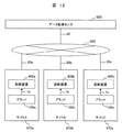
図1は、本発明の第1の実施例である診断装置400を説明するブロック図である。診断装置400を用いて、プラント100を監視する。
FIG. 1 is a block diagram for explaining a
診断装置400は、演算装置として監視データ生成部700、分類部750、検知部800を備えている。監視データ生成部700は、運転パターン評価部710、類似プラント選定部720、疑似信号生成部730で構成し、検知部800は状態変化検知部810、異常検知部820で構成する。
The
また、診断装置400はデータベースとして計測信号データベース510、プラントデータベース520、診断モデルデータベース530を備える。尚、図1においてはデータベースをDBと略記している。計測信号データベース510、プラントデータベース520、診断モデルデータベース530には、電子化された情報が保存されており、通常電子ファイル(電子データ)と呼ばれる形態で情報が保存される。
The
また、診断装置400は、外部とのインターフェイスとして外部入力インターフェイス410及び外部出力インターフェイス420を備えている。
Further, the
そして、外部入力インターフェイス410を介してプラント100の運転状態である各種状態量を計測した計測信号1と、運転管理室900に備えられているキーボード920及びマウス930で構成される外部入力装置910の操作で作成する外部入力信号2が診断装置400に取り込まれる。また、外部出力インターフェイス420を介して、画像表示情報11を運転管理室900に備えられている画像表示装置940に出力する。
And the
図1に示した診断装置400において、プラント100の各種状態量を計測した計測信号1は外部入力インターフェイス410を介して取り込まれる。診断装置400に取り込まれた計測信号3は、計測信号データベース510に保存する。なお計測信号1の多くはアナログ量であるが、診断装置400に取り込まれた計測信号3は時系列的なディジタル量であるため記号を区別している。
In the
診断装置400は、モデル構築処理と診断処理の二つの処理モードを持つ。モデル構築処理では、正常状態の計測信号を用いて、診断モデルを構築する。診断モデルはクラスタリング技術により構築され、正常状態の計測信号がいくつかのデータグループに分類される。診断処理では、診断する時刻の計測信号を処理する。計測信号が正常状態の時と同じ特性であれば、診断モデルのデータグループのいずれか1つに分類される。特性が異なる場合は、診断モデルのデータグループには属さないことになる。
The
プラント100にて異常が発生すると、計測信号の特性が正常状態とは異なる。そのため、正常状態の計測信号を用いて構築した診断モデルのデータグループに、診断の計測信号が分類されない。この特性を利用して、先に述べた特許文献1では計測信号が診断モデルのデータグループに属さない場合に異常と診断する。
When an abnormality occurs in the
しかし、プラント100の特性は、プラントの運転パターンに応じて変化する。ここで運転パターンとは、プラントが設置されている場所の環境条件(大気温度、湿度など)や、オペレータの操作で決定する値(プラントで生成する発電量の指令値)など、機器特性と直接関係しない外的環境因子である。
However, the characteristics of the
運転状態が正常であっても、運転パターンが異なると計測信号の傾向も変化する。そのため、特許文献1の技術を適用すると正常状態を異常と判定する誤報が発生する可能性がある。
Even if the driving state is normal, the tendency of the measurement signal changes if the driving pattern is different. For this reason, when the technique of
そこで、本発明では状態変化の検知と異常の検知の2種類の検知方式を組み合わせて診断することで、誤報の発生を回避する。 Therefore, in the present invention, the occurrence of false alarms is avoided by diagnosing by combining two types of detection methods, namely, state change detection and abnormality detection.
まず、モデル構築処理モードの動作を述べる。モデル構築処理モードでは、状態変化の検知に用いる監視モデルを構築する。 First, the operation in the model construction processing mode will be described. In the model construction processing mode, a monitoring model used for detecting a state change is constructed.
まず、監視データ生成部700では、予め定められたデータ項目について、所定期間の計測信号情報4を計測信号データベース510から抽出する。ここでの所定期間はプラント100の運用サイクルに応じて任意に設定でき、DSS(Daily Start and Stop)運転の場合は1日、WSS(Weekly Start and Stop)運転の場合は1週間、MSS(Monthly Start and Stop)運転の場合は1か月などに設定する。監視データ生成部700で抽出した計測信号情報4を含む監視データ情報6は分類部750に送信される。分類部750では、監視データ情報6をクラスタリング技術により分類する。分類結果である分類結果情報7は、診断モデルデータベース530に送信され、保存される。
First, the monitoring
次に、診断処理モードの動作を述べる。診断処理モードでは、まずモデル構築処理モードで構築した診断モデルを用いて状態変化検知部810にて状態変化有無を判定する。 Next, the operation in the diagnostic processing mode will be described. In the diagnosis processing mode, first, the state change detection unit 810 determines whether there is a state change using the diagnosis model constructed in the model construction processing mode.
状態変化を検知した場合は、同じ運転パターンのデータを用いて診断モデルを構築し、異常検知部820にて異常有無を判定する。もし同じ運転パターンのデータがない場合は、類似プラントの過去の運転データを活用して正常データの疑似データを作成し、疑似データを用いて構築した診断モデルで診断する。診断処理モードの詳細は、図5を用いて後述する。診断処理モードを動作させて得られる検知結果情報10は、外部出力インターフェイス420に出力する。
When a state change is detected, a diagnosis model is constructed using data of the same operation pattern, and the
なお、本実施例の診断装置400においては、監視データ生成部700、分類部750、検知部800、計測信号データベース510、プラントデータベース520、診断モデルデータベース530が診断装置400の内部に備えられているが、これらの一部の装置を診断装置400の外部に配置し、データのみを装置間で通信するようにしてもよい。
In the
また、図示していないが、診断装置400に設置された計測信号データベース510、プラントデータベース520、診断モデルデータベース530に保存されている情報は、運転管理室900とデータ通信できるようになっており、データベースの情報を画像表示装置940に表示できる。また、これらの情報は、キーボード920とマウス930で構成する外部入力装置910を操作して生成する外部入力信号2で修正できる。
Although not shown, the information stored in the
また、本発明の実施形態として、診断装置400を動作させて得られた情報を運転員に提供する情報提供サービス、診断装置400を搭載した運転制御装置も含まれる。
In addition, as an embodiment of the present invention, an information providing service for providing information obtained by operating the
図2は、診断装置400のモデル構築処理モードと診断モードを実行するタイミングを説明する図である。所定の設定期間毎に正常状態学習モード(モデル構築処理モード)を動作させ、サンプリング周期毎に診断処理モードを動作させて診断する。
FIG. 2 is a diagram illustrating the timing of executing the model construction processing mode and the diagnostic mode of the
図3は、分類部750を説明する図である。本実施例では、信号を分類する技術として、適応共鳴理論(Adaptive Resonance Theory:ART)を適用した場合について述べる。尚、ベクトル量子化、サポートベクターマシン等、他のクラスタリング手法を用いることもできる。
FIG. 3 is a diagram illustrating the
図3(a)に示すように、データ分類機能はデータ前処理装置610とARTモジュール620で構成する。データ前処理装置610は、運転データをARTモジュール620の入力データに変換する。
As shown in FIG. 3A, the data classification function includes a
以下に、前記データ前処理装置610及びARTモジュール620によるそれらの手順について説明する。
Hereinafter, those procedures performed by the
まず、データ前処理装置610において、計測項目毎にデータを正規化する。計測信号を正規化したデータNxi(n)及び正規化したデータの補数CNxi(n)(=1−Nxi(n))を含むデータを入力データIi(n)とする。この入力データIi(n)が、ARTモジュール620に入力される。
First, the
ARTモジュール620においては、入力データである分類用データ信号702、もしくは検知用データ信号6を複数のカテゴリに分類する。
In the
ARTモジュール620は、F0レイヤー621、F1レイヤー622、F2レイヤー623、メモリ624及び選択サブシステム625を備え、これらは相互に結合している。F1レイヤー622及びF2レイヤー623は、重み係数を介して結合している。重み係数は、入力データが分類されるカテゴリのプロトタイプ(原型)を表している。ここで、プロトタイプとは、カテゴリの代表値を表すものである。
The
次に、ARTモジュール620のアルゴリズムについて説明する。ARTモジュール620に入力データが入力された場合のアルゴリズムの概要は、下記の処理1〜処理5のようになる。
Next, the algorithm of the
処理1:F0レイヤー621により入力ベクトルを正規化し、ノイズを除去する。
Process 1: The input vector is normalized by the
処理2:F1レイヤー622に入力された入力データと重み係数との比較により、ふさわしいカテゴリの候補を選択する。
Process 2: A suitable category candidate is selected by comparing the input data input to the
処理3:選択サブシステム625で選択したカテゴリの妥当性がパラメータρとの比により評価される。妥当と判断されれば、入力データはそのカテゴリに分類され、処理4に進む。一方、妥当と判断されなければ、そのカテゴリはリセットされ、他のカテゴリからふさわしいカテゴリの候補を選択する(処理2を繰り返す)。パラメータρの値を大きくするとカテゴリの分類が細かくなり、ρの値を小さくすると分類が粗くなる。このパラメータρをビジランス(vigilance)パラメータと呼ぶ。
Process 3: The validity of the category selected by the
処理4:処理2において全ての既存のカテゴリがリセットされると、入力データが新規カテゴリに属すると判断され、新規カテゴリのプロトタイプを表す新しい重み係数を生成する。
Process 4: When all the existing categories are reset in
処理5:入力データがカテゴリJに分類されると、カテゴリJに対応する重み係数WJ(new)は、過去の重み係数WJ(old)及び入力データp(又は入力データから派生したデータ)を用いて下記(1)式により更新される。
WJ(new)=Kw・p+(1−Kw)・WJ(old) ・・・(1)
ここで、Kwは、学習率パラメータ(0<Kw<1)であり、入力ベクトルを新しい重み係数に反映させる度合いを決定する値である。
Process 5: When input data is classified into category J, weight coefficient WJ (new) corresponding to category J uses past weight coefficient WJ (old) and input data p (or data derived from input data). And updated by the following equation (1).
WJ (new) = Kw.p + (1-Kw) .WJ (old) (1)
Here, Kw is a learning rate parameter (0 <Kw <1), and is a value that determines the degree to which the input vector is reflected in the new weighting factor.
尚、(1)式及び後述する(2)式乃至(12)式の各演算式は前記ARTモジュール620に組み込まれている。
The arithmetic expressions (1) and expressions (2) to (12) described later are incorporated in the
ARTモジュール620のデータ分類アルゴリズムの特徴は、上記の処理4にある。つまり、処理4においては、学習した時のパターンと異なる入力データが入力された場合、記録されているパターンを変更せずに新しいパターンを記録することができる。このため、過去に学習したパターンを記録しながら、新たなパターンを記録することが可能となる。
The feature of the data classification algorithm of the
このように、入力データとして予め与えた運転データを与えると、ARTモジュール620は与えられたパターンを学習する。したがって、学習済みのARTモジュール620に新たな入力データが入力されると、上記アルゴリズムにより、過去におけるどのパターンに近いかを判定することができる。また、過去に経験したことのないパターンであれば、新規カテゴリに分類される。
As described above, when the operation data given in advance is given as input data, the
図3(b)は、F0レイヤー621の構成を示すブロック図である。F0レイヤー621では、入力データIを各時刻で再度正規化し、F1レイヤー621、及び選択サブシステム625に入力する正規化入力ベクトルu0を作成する。
FIG. 3B is a block diagram showing the configuration of the
始めに、入力データIから、(2)式に従ってw0を計算する。ここで、aは定数である。なお図面や式中においてこれらの記号に下付小文字としてiを付すことがあるが、これはi
番目のデータの処理であることを意味している。
First, w 0 is calculated from the input data I according to the equation (2). Here, a is a constant. In the drawings and formulas, i may be added to these symbols as subscripts.
It is the processing of the second data.
![]()
![]()
次に、w0を正規化したx0を、(3)式を用いて計算する。なお(3)式において、x0の両側の二重縦線はノルムを表す記号である。 Next, x 0 obtained by normalizing w 0 is calculated using the equation (3). In yet (3), on both sides of the double vertical lines x 0 is a symbol representing the norm.

そして、(4)式を用いて、x0からノイズを除去したv0を計算する。ただし、θはノイズを除去するための定数である。(4)式の計算により、微小な値は0となるため、入力データのノイズが除去される。 Then, using the (4) equation, to calculate the v 0 obtained by removing noise from x 0. However, θ is a constant for removing noise. Since the minute value becomes 0 by the calculation of the equation (4), noise of the input data is removed.
最後に、(5)式を用いて正規化入力ベクトルu0を求める。u0はF1レイヤーの入力となる。 Finally, a normalized input vector u 0 is obtained using equation (5). u 0 is the input of the F1 layer.
図3(c)は、F1レイヤー622の構成を示すブロック図である。F1レイヤー622では、式(5)で求めたu0を短期記憶として保持し、F2レイヤー722に入力するpiを計算する。F2レイヤーの計算式をまとめて(6)式〜(12)式に示す。ただし、a、bは定数、fは(4)式で示した関数、TjはF2レイヤー722で計算する適合度である。
FIG. 3C is a block diagram showing the configuration of the
![]()
![]()
![]()
![]()
![]()
![]()
ただし、 However,
図4は分類部750で監視データ情報6に含まれる計測信号、もしくは疑似信号を分類した結果を説明する図である。
FIG. 4 is a diagram for explaining a result of classifying measurement signals or pseudo signals included in the
図4(a)は、プラント100から取得した計測信号1、もしくは疑似信号を、カテゴリに分類した結果を説明する図である。横軸は、時間、縦軸は計測信号、カテゴリ番号である。この結果によれば、正常期間において項目A、Bはカテゴリー番号1に分類され、その後順次カテゴリー番号2、3に分類されるように時間変化している。また診断期間において、当初カテゴリー番号2に分類されていたものが、短時間でカテゴリー番号4に分類されるように状態が変化した。
FIG. 4A is a diagram for explaining the result of classifying the
図4(b)は、分類部750にてカテゴリに分類した分類結果の一例を示す図である。この例では、計測信号のうちの2項目を表示したものであり、2次元のグラフで表記した。また、縦軸及び横軸は、それぞれの項目の計測信号を規格化して示した。この表示結果によれば、カテゴリー番号1は項目Aが大きく項目Bが小さいグループ、カテゴリー番号2は項目Aと項目Bが共に小さいグループ、カテゴリー番号3は項目Bが大きく項目Aが小さいグループ、カテゴリー番号4は項目Aと項目Bが共に大きいグループに分類したものであることが見て取れる。このように、計測信号は、図3(a)のARTモジュール620によって、複数のカテゴリ630(図4(b)に示す円)に分割される。1つの円が、1つのカテゴリに相当する。
FIG. 4B is a diagram illustrating an example of the classification result classified into categories by the
図4(a)に示すように、診断開始前の正常期間のデータは、カテゴリ1〜3に分類された。カテゴリ1〜3に分類されたデータがモデルデータである。これに対し、監視開始後の診断期間前半のデータはカテゴリ2に分類されており、モデルデータと同じカテゴリ1〜3に含まれるデータである。この場合、データの傾向が同じであることから、状態は変化していないと判断する。
As shown to Fig.4 (a), the data of the normal period before the diagnosis start were classified into the categories 1-3. Data classified into
一方、監視開始後の診断期間後半のデータはカテゴリ4に分類されており、モデルデータ(カテゴリ1〜3)と異なるカテゴリに分類されている。データの傾向が異なることから、プラントの状態が変化したと判断する。
On the other hand, data in the latter half of the diagnosis period after the start of monitoring is classified into
尚、本実施例においては、2項目の計測信号A、Bをカテゴリに分類する例を述べたが、3項目以上の計測信号について多次元の座標を用いてカテゴリに分類することもできる。 In the present embodiment, an example in which two measurement signals A and B are classified into categories has been described. However, three or more measurement signals can be classified into categories using multidimensional coordinates.
図5は、診断装置400の診断モードの動作フローチャート図である。
FIG. 5 is an operation flowchart of the diagnosis mode of the
本発明では状態変化検知部810で診断した結果として新規カテゴリが発生した時には、運転パターンが変化しているかどうかを判定する。運転パターンが変化している場合には異常検知部820で改めて診断する。本方式により、運転パターン変化を異常と診断する誤報の発生を回避すると同時に、正常状態の運転データを収集する期間を短縮できる。
In the present invention, when a new category is generated as a result of diagnosis by the state change detection unit 810, it is determined whether or not the driving pattern has changed. When the driving pattern changes, the
図5の診断モードの動作フローチャートでは、まずステップ1000において、状態変化検知部810を動作させて診断する。次にステップ1010では、ステップ1000の診断結果を評価し、新規カテゴリが発生しなかった場合はステップ1100(正常判定)に進み、新規カテゴリが発生した場合はステップ1020に進む。 In the operation flowchart of the diagnosis mode of FIG. 5, first, in step 1000, the state change detection unit 810 is operated to make a diagnosis. Next, in step 1010, the diagnosis result in step 1000 is evaluated. If no new category has occurred, the process proceeds to step 1100 (normal determination), and if a new category has occurred, the process proceeds to step 1020.
ステップ1020では、運転パターン評価部710を動作させて運転パターンの変化有無を確認し、変化無しの場合はステップ1110(異常判定)へ進み、変化有りの場合は1030に進む。
In step 1020, the operation
ステップ1030では、図6(a)に例示する計測信号データベース510に対して現時刻(状態変化を検知した時刻)と同じ運転パターンの期間が存在するか否かを検索し、同じ運転パターンの期間が存在しない場合はステップ1040へ進み、同じ運転パターンの期間が存在する場合はステップ1060へ進む。なお図5のステップ1030では、現時刻と同じ運転パターンの期間が存在するか否かを、過去データ(現時刻と同じ運転パターンの期間における)の有無として表記している。例えば図6(a)に例示する計測信号データベース510について、時刻10:01が現時刻であるとして、同じ運転パターンを検索したときにこれが時刻10:00であったとした場合に、この時の項目A,B,Cについてのデータが過去データとして抽出されることになる。
In step 1030, it searches whether a period of the same driving pattern with respect to the
ステップ1040では、運転員によりあらかじめ設定された条件に基づいて疑似信号作成の有無を決定し、疑似信号を作成する場合はステップ1050へ進み、作成しない場合はステップ1120(予兆判定)へ進む。ここで予兆判定とは、プラントの運転状態が変化しているが異常が発生しているとは限らない状態のことであり、異常発生の最終判断は運転員が実施する。 In step 1040, whether or not a pseudo signal is to be created is determined based on conditions set in advance by the operator. If a pseudo signal is to be created, the process proceeds to step 1050. If not, the process proceeds to step 1120 (prediction determination). Here, the sign determination is a state where the operation state of the plant is changed but an abnormality does not always occur, and the final determination of the occurrence of the abnormality is performed by the operator.
ステップ1050では、まず類似プラント選定部720を動作させて、診断対象のプラント100と類似したプラントをプラントデータベース520から抽出する。類似プラント選定部720では、診断対象のプラントの設計情報と、プラントデータベース520に保存されているプラントの設計情報を比較し、以下の(13)式の評価関数Fが最小となるプラントを抽出する。但し(13)式においてCiは(14)式で表される。ここで、すでに述べたようにPはF2レイヤー722の入力であり、wは(2)式で求めた値である。
In step 1050, first, the similar
F = Σwi×Ci ・・・(13)
Ci = (P1i/P2i)^2 ・・・(14)
次に疑似信号生成部730にて疑似信号を作成し、ステップ1060へ進む。尚、疑似
信号生成部730の詳細は図7を用いて後述する。
F = Σwi × Ci (13)
Ci = (P1i / P2i) ^ 2 (14)
Next, the pseudo
ステップ1060では、計測信号データベース510から抽出した同一の運転パターンの計測信号、もしくはステップ1050で生成した疑似信号を用いて診断モデルを構築し、本診断モデルを用いて異常検知部820にて診断する。ステップ1070では、ステップ1060での新規カテゴリ発生有無を評価し、発生しなかった場合はステップ1130(正常判定)に進み、発生した場合はステップ1140(異常判定)に進む。
In step 1060, a diagnostic model is constructed using the measurement signal of the same operation pattern extracted from the
ステップ1100、1110、1120、1130、1140を実行した後、ステップ1080にて終了判定を実施する。プラント運転員から診断システムの停止要請があった場合はシステムを終了させ、それ以外の場合はステップ1000に戻る。 After executing steps 1100, 1110, 1120, 1130, and 1140, end determination is performed in step 1080. If there is a request from the plant operator to stop the diagnostic system, the system is terminated. Otherwise, the process returns to step 1000.
図5に一連の処理フローを示す本発明の診断装置では、ステップ1060にて同一の運転パターンの計測信号を用いた診断モデルを用いて診断を実行することで、ステップ1010で診断する場合と比較して運転パターン変更に伴う誤報の発生を抑制し、診断精度を向上できる。また、診断対象プラントの同一運転データがない場合はステップ1050にて疑似信号を生成して診断モデルを構築できる。従って、診断対象プラントの運転データは短期間で良いため、診断装置導入の時間を短縮する効果が得られる。 In the diagnostic apparatus of the present invention showing a series of processing flows in FIG. 5, the diagnosis is executed using the diagnostic model using the measurement signal of the same operation pattern in Step 1060, which is compared with the case where the diagnosis is performed in Step 1010. Thus, it is possible to suppress the occurrence of false alarms accompanying the change of driving pattern and improve the diagnostic accuracy. Further, if there is no identical operation data of the diagnosis target plant, a diagnosis signal can be constructed by generating a pseudo signal in step 1050. Therefore, since the operation data of the diagnosis target plant may be a short period, the effect of shortening the time for introducing the diagnosis apparatus can be obtained.
図6は、計測信号データベース510、プラントデータベース520、診断モデルデータベース530に保存されるデータの態様を説明する図である。なおここではモニタ画面上にこれらのデータを表記した状態を示している。従って、モニタ画面上で、適宜左右、上下方向のスクロールにより、表示範囲以上のデータを参照可能である。またタブにより複数の監視グループを選択することも可能である。
FIG. 6 is a diagram for explaining an aspect of data stored in the
図6(a)は、計測信号データベース510に保存されるデータの態様を示している。ここには、プラント100で計測した運転データである計測信号1(図では、データ項目A、B、Cを記載)の値が、サンプリング周期(縦軸の時刻)毎に保存される。また表示画面511において縦横に移動可能なスクロールボックス512及び513を用いることにより、広範囲のデータをスクロール表示することができる。
FIG. 6A shows the mode of data stored in the
図6(b)は、プラントデータベース520に保存されるデータの態様を示している。ここには、プラント名、出力、蒸気圧力、蒸気温度など、各種プラントの設計値が保存される。また、プラントデータベース520には、各種プラントの過去の運転データが、図6(a)に示したフォーマットで保存される。さらにプラントデータベース520には、センサの配置位置や計測点数などのセンサ設置情報、大気温度や湿度などの環境情報が保存される。
FIG. 6B shows the mode of data stored in the
図6(c)は、診断モデルデータベース530に保存されるデータの態様を示している。ここには、カテゴリ番号と重み係数との関係が診断モデル毎(監視グループのタブ選択により選択)に保存される。ここで、重み係数とは、カテゴリの中心座標のことである。
FIG. 6C shows a mode of data stored in the
図7(a)は、疑似信号生成部730を説明するブロック図である。疑似信号生成部730は、演算装置としてシミュレータ732、パラメータ推定部734を備え、メモリとしてパラメータデータ735を備える。尚、メモリはデータベースの形態としても良い。
FIG. 7A is a block diagram illustrating the pseudo
シミュレータ732では、計測信号データベース510とプラントデータベース520に保存されている情報を用いて、正常状態の計測信号の疑似データを以下のモデル式(15)で計算する。
The
dx/dt = f(x、α、β) ・・・(15)
上記の式において、xはプラント100の状態量、αは類似プラントの計測データで調整する調整パラメータ、βはプラントデータベース520に保存されているプラントの設計値で決定する固定パラメータである。
dx / dt = f (x, α, β) (15)
In the above formula, x is a state quantity of the
調整パラメータαはパラメータ推定部734で推定する。本発明は、パラメータの推定方法に限定されるものではなく、各種の推定アルゴリズムを用いて良い。
The adjustment parameter α is estimated by the
モデル式(15)とプラント特性には誤差があり、これをモデル化誤差と呼ぶ。本発明ではモデル化誤差を、調整パラメータαが一定範囲で変動することを仮定することにより模擬する。本実施例では、調整パラメータαの代表値と変動範囲(標準偏差)を推定する方法としてベイズ学習法を用いる。 There is an error between the model formula (15) and the plant characteristic, which is called a modeling error. In the present invention, the modeling error is simulated by assuming that the adjustment parameter α varies within a certain range. In the present embodiment, a Bayesian learning method is used as a method for estimating the representative value and variation range (standard deviation) of the adjustment parameter α.
ベイズ学習法は、非特許文献1に記載されているため、以下ではアルゴリズムの詳細は省略し、パラメータ推定部734とシミュレータ732の動作結果を説明する。
Since the Bayesian learning method is described in
図7(b)は、パラメータデータ735に生成されたパラメータデータの例を表示画面状に表示した事例を示している。属性の欄では、類似プラントの計測データで調整する調整パラメータαと、プラントデータベース520に保存されているプラントの設計値で決定する固定パラメータβとを区分して表記し、これらパラメータの名称と共に、代表値と標準偏差を表示(記憶)している。
FIG. 7B shows an example in which an example of parameter data generated in the
図8は、パラメータ推定部734とシミュレータ732の動作結果を説明する図である。このうち、図8(a)は、パラメータ推定部734を動作させた結果として得られるパラメータサンプル値を説明する図である。ベイズ推定法のマルコフ連鎖モンテカルロ法ではパラメータの推定サンプル値を逐次発生させる。パラメータのサンプル値は、サンプリング回数が少ない場合は変化が大きいが、サンプリング回数が多くなるに従って変化が小さくなる。サンプリング回数が一定値以上の区間を評価区間とし、評価区間のパラメータのサンプル値から平均値、標準偏差を計算する。
FIG. 8 is a diagram for explaining the operation results of the
図8(b)は、シミュレータ732で作成した疑似データの例である。調整パラメータをそのサンプル値の平均値に設定してシミュレータを動作させたときの値を実線で、標準偏差の範囲で変化させてシミュレータを動作させた時の値の範囲を点線で示している。この例では項目Aは、ほぼ一定の上下限値の範囲内でほぼ一定とを保つ傾向を示し、項目Bは周期変動する上下限値の範囲内で同様に周期変動する傾向を示す疑似データであることが理解できる。
FIG. 8B is an example of pseudo data created by the
図8(c)(d)は、疑似データの2項目を表示したものであり、2次元のグラフで表記した。図8(c)はパラメータを変化させた時、図8(d)は平均値を用いて疑似データを作成した場合のグラフである。 FIGS. 8C and 8D show two items of pseudo data, which are represented by a two-dimensional graph. FIG. 8C is a graph when pseudo data is created using an average value when parameters are changed.
パラメータを変化させることにより、モデル誤差を考慮し、計測信号の値のとりうる範囲を網羅した疑似信号を生成できる。この疑似信号を用いて診断モデルを構築することにより、モデル誤差に起因する誤報発生を抑制できる。また、平均値で作成した疑似データを分類して構築した診断モデルと、パラメータを変動させた時の疑似データを分類して構築した診断モデルの2つの診断モデルを用いて診断し、それぞれの診断結果を出力するようにしても良い。 By changing the parameters, it is possible to generate a pseudo signal that covers the range of values of the measurement signal in consideration of the model error. By constructing a diagnostic model using this pseudo signal, it is possible to suppress the occurrence of false alarms due to model errors. In addition, diagnosis is performed using two diagnostic models: a diagnostic model constructed by classifying pseudo data created with average values, and a diagnostic model constructed by classifying pseudo data when parameters are changed. The result may be output.
図9は、画像表示装置940に表示する画面の実施例を説明する図である。このうち図9(a)は図5のフローチャートでの判定結果を表示する画面であり、監視グループ毎の診断結果(正常判定、異常判定、予兆判定のいずれか)を表示する。
FIG. 9 is a diagram illustrating an example of a screen displayed on the
図9(b)は類似プラントの計測信号と疑似信号、疑似信号をカテゴリに分類した結果、および診断対象プラントと類似プラントの設計情報を表示する。本画面により、類似プラント選定部720、疑似信号生成部730の動作結果を確認できる。この表示画面によれば、診断対象プラントAAAAの出力、蒸気圧力、蒸気温度がそれぞれ100、25、500であるとき、類似プラントBBBBのそれは90、25、520であることが対比表示されている。
FIG. 9B displays the measurement signal and pseudo signal of the similar plant, the result of classifying the pseudo signal into the category, and the design information of the diagnosis target plant and the similar plant. The operation results of the similar
図9(c)はカテゴリの分類性能を決めるビジランスパラメータρを変更するのに用いる画面である。図9(c)でρを変更したことの影響を、図9(b)で評価できる。評価結果に基づき、ρを適正な値に設定できる。 FIG. 9C shows a screen used to change the vigilance parameter ρ that determines the classification performance of the category. The effect of changing ρ in FIG. 9C can be evaluated in FIG. 9B. Based on the evaluation result, ρ can be set to an appropriate value.
図10はプラント100がガスタービンプラントであるときの実施形態を示した図である。図10(a)は診断対象のプラント100がガスタービンプラントである場合の構成を説明する図である。プラント100は、ガスタービン発電機110、制御装置120及びデータ送信装置130を含む。ガスタービン発電機110は、発電機111、圧縮機112、燃焼器113及びタービン114を含む。
FIG. 10 is a diagram showing an embodiment when the
発電に際しては、圧縮機112にて吸い込んだ空気を圧縮して圧縮空気とし、この圧縮空気を燃焼器113に送り、燃料と混合して燃焼する。燃焼により発生した高圧ガスを用いてタービン114を回転させ、発電機111により発電を行う。
At the time of power generation, the air sucked by the
制御装置120においては、電力需要に応じてガスタービン発電機110の出力を制御する。また、制御装置120は、ガスタービン発電機110に設置されたセンサ(図示せず)で計測した運転データ102を入力データとしている。運転データ102は、吸気温度、燃料投入量、タービン排ガス温度、タービン回転数、発電機発電量、タービン軸振動などの状態量であり、サンプリング周期毎に計測している。また、大気温度などの気象情報も計測している。
In the
制御装置120においては、これらの運転データ102を用いて、ガスタービン発電機110を制御するための制御信号101を算出する。また、制御装置120では、運転データ102の値が予め設定した範囲を逸脱した時に警報を発生させる処理を実施している。警報信号は、運転データ102が予め設定した範囲を逸脱した時に1、範囲内の時は0のデジタル信号として処理する。警報信号が1の時は、音や画面表示などで、警報の内容をオペレータに通知する。
In the
信号データ送信装置130は、制御装置120で計測した運転データ102、及び制御装置120で算出した制御信号101、および警報信号を含む計測信号1をプラント状態監視装置200に送信する。
The signal
図10(b)に示すように、本プラントにおける起動時の運転パターンのバリエーションとして、起動モードA、制御モードBがある。起動モードAとは、機器の保温状態に応じた起動方法であり、ホットスタート、ウォームスタート、コールドスタートなどのモードがある。また、制御モードBとは制御目的に応じて決定する制御方法であり、起動時間最短制御、寿命消費量最小制御、起動中発電量最大制御などのモードがある。 As shown in FIG. 10B, there are a startup mode A and a control mode B as variations of the operation pattern at the start-up in this plant. The activation mode A is an activation method according to the heat insulation state of the device, and includes modes such as hot start, warm start, and cold start. The control mode B is a control method that is determined according to the control purpose, and includes modes such as the shortest start-up time control, the minimum life consumption control, and the maximum power generation amount control during start-up.
本発明を実現する場合に、図1の運転パターン評価部710では、起動モードAと制御モードBのそれぞれが属するモードに応じて、運転パターンを区別するのがよい。尚、本発明を実施するに当たり、モードの種類、各モードの内容についての制限はないことは言うまでもない。
When the present invention is realized, the operation
図11はプラント100がボイラプラントであるときの実施形態を示した図である。図11(a)は、診断対象のプラント100がボイラプラントである場合の構成を示す図である。このプラントは、ボイラ200、ボイラ200で発生させた蒸気により駆動する蒸気タービン300を主構成要素とする火力発電プラントである(発電機は図示していない)。ボイラプラント100は、負荷要求指令に基づいて、指定された負荷(発電出力)に制御する。蒸気加減弁290の弁開度を調節することで、タービン300へ導かれる蒸気流量261が変化し発電出力が変化する。
FIG. 11 is a diagram showing an embodiment when the
その他にも水・蒸気系統には、蒸気タービン300から出た蒸気を冷却して液体にする復水器310、復水器310で冷却された水をボイラ給水として再びボイラ200へ送り込む給水ポンプ320がある。また、図示していないが、実際のプラントには蒸気タービン300の途中段から抜き出した一部の蒸気を加熱源としてボイラ給水を予熱する給水加熱器もある。
In addition, the water / steam system includes a
一方、ボイラから排出される燃焼ガス201の系統には、排ガスを浄化するための排ガス処理装置330、浄化したガス331を放出する煙突340がある。
On the other hand, in the system of the
燃料である石炭381は燃料供給量調整弁380を介して、石炭粉砕機(ミル)350に送られる。また、石炭搬送と燃焼調整にもちいる空気382は空気量調整弁370を介して、石炭粉砕機350とバーナ310に供給される。石炭粉砕機350で粉末(微粉炭)となった石炭は、空気で搬送されてバーナ210に供給される。バーナ210の上部にはアフタエアポート220が配置され、アフタエアポート220には空気383が空気量調整弁360を介して供給される。
次にボイラ200の構成について説明する。燃料を燃焼させるバーナ210がある火炉は炉内が高温になるため、壁面全体を冷却すると共に燃焼ガスの熱を回収する水壁230と呼ばれる冷却壁がある。ボイラ200内には他にも節炭器280、1次過熱器270、2次過熱器240、3次過熱器250、4次過熱器260からなる熱交換器があり、これらによって燃焼ガスの熱を回収して高温蒸気を生成する。
Next, the configuration of the
尚、図中には記載していないが、プラントには、ガスの組成、温度、圧力や、蒸気の温度、圧力、熱交換器のメタル温度などを計測するためのセンサーが多数配置されており、この計測結果はデータ送信装置390から計測情報1としてボイラチューブリーク検出装置400に送信される。また、図示していないが、ボイラのバーナ210は火炉前後に水平方向に複数本、高さ方向に複数段設置し、アフタエアポートは、火炉前後に水平方向に複数本配置するのが一般的である。
Although not shown in the figure, the plant has many sensors for measuring gas composition, temperature, pressure, steam temperature, pressure, heat exchanger metal temperature, etc. The measurement result is transmitted as
図11(b)に示すように、本プラントにおける運転パターンのバリエーションとして、バーナパターン、燃料種類モード、制御モードがある。 As shown in FIG. 11B, there are a burner pattern, a fuel type mode, and a control mode as variations of the operation pattern in this plant.
ボイラのバーナ210は火炉前後に水平方向に複数本、高さ方向に複数段設置されており、プラントの出力に応じて点火するバーナの本数を決定する。点火するバーナの位置は任意に設定できるため、点火バーナの組み合わせパターンは複数ある。また、ボイラにて使用する石炭の銘柄により、石炭の成分が異なる。バーナパターン、燃料種類が異なると火炉の熱吸収特性が変化するため、蒸気温度等のプラント特性に影響する。また、制御モードとは制御目的に応じて決定する制御方法であり、燃料消費量最小制御、NOx最小制御などのモードがある。
A plurality of
本発明を実現する場合に、図1の運転パターン評価部710では、バーナパターンモードA、燃料種類モードB、制御モードCに応じて運転パターンを区別する。尚、本発明を実施するに当たり、モードの種類、各モードの内容についての制限はないことは言うまでもない。
When realizing the present invention, the operation
図12は、本発明の第4の実施例を説明するブロック図である。 FIG. 12 is a block diagram for explaining a fourth embodiment of the present invention.
本実施例では、データ監視センタ950、サイト970が、情報通信ネットワーク960で相互に接続されている。発電所970は複数あり、本実施例では3つのサイトを記載したが、任意の数のサイトを接続するように構成してもよい。サイト間で通信する通信情報20には、モデル式、及び調整パラメータαの情報が含まれる。データ監視センタ950では、通信情報20にプラントの設計情報、及び計測信号が含まれていないことを確認する。
In this embodiment, a
実施例1で述べた診断装置400に備えられているプラントデータベース520には、診断対象のプラント設計情報に加えて、他プラントの設計情報、及び計測信号が保存されている。しかし、他プラントの設計情報、計測信号を入手することは一般に難しい。また、これらの情報の管理には情報セキュリティ事故防止のために多大なコストが必要となる。
In the
本実施例では、図示していないが診断装置400a−400cに備えられているプラントデータベース520には診断対象のプラント設計情報を保存し、他プラントの設計情報、及び計測信号は保存しない。疑似信号は、サイト間で通信する通信情報12に含まれるモデル式、調整パラメータ値を用いて、式(4)で計算する。
In the present embodiment, although not shown, plant design information to be diagnosed is stored in the
本実施例では、プラントの設計情報、及び計測信号の情報を他サイトに提供することなく、各サイトで診断装置を動作させることが可能となり、情報セキュリティを強化する効果が得られる。 In this embodiment, it is possible to operate the diagnostic apparatus at each site without providing plant design information and measurement signal information to other sites, and the effect of enhancing information security can be obtained.
本発明は、診断装置として、火力発電プラント、原子力発電プラントなど、各種プラントに適用可能である。 The present invention is applicable to various plants such as a thermal power plant and a nuclear power plant as a diagnostic device.
1:計測信号
2:外部入力信号
3:計測信号
4:計測信号
5:プラントデータベース情報
6:監視データ情報
7:分類結果情報
8:診断モデルデータベース情報
9:診断モデルデータベース情報
10:検知結果情報
11:画像表示情報
100:プラント
400:診断装置
410:外部入力インターフェイス
420:外部出力インターフェイス
510:計測信号データベース
520:プラントデータベース
530:診断モデルデータベース
700:監視データ生成部
710:運転パターン評価部
720:類似プラント選定部
730:疑似信号生成部
800:検知部
810:状態変化検知部
820:異常検知部
900:運転管理室
910:外部入力装置
920:キーボード
930:マウス
940:画像表示装置
1: Measurement signal 2: External input signal 3: Measurement signal 4: Measurement signal 5: Plant database information 6: Monitoring data information 7: Classification result information 8: Diagnostic model database information 9: Diagnostic model database information 10: Detection result information 11 : Image display information 100: Plant 400: Diagnosis device 410: External input interface 420: External output interface 510: Measurement signal database 520: Plant database 530: Diagnosis model database 700: Monitoring data generation unit 710: Operation pattern evaluation unit 720: Similar Plant selection unit 730: pseudo signal generation unit 800: detection unit 810: state change detection unit 820: abnormality detection unit 900: operation management room 910: external input device 920: keyboard 930: mouse 940: image display device
Claims (11)
診断対象プラントの状態量を計測した計測信号を記憶する計測信号データベースと、
各種プラントの過去の運転データを記憶するプラントデータベースを備え、
前記検知部は、
所定期間のデータで構築した診断モデルを用いて状態変化を検知する状態変化検知部と、
機器特性と直接関係しない外的環境因子である運転パターンについて、状態変化を検知したときと同じ運転パターンのデータで構築した診断モデルを用いて異常発生有無を検知する異常検知部と、
前記同じ運転パターンのデータは、前記計測信号データベースに記憶された前記診断対象プラントの計測信号を使用し、もしくは前記計測信号データベースに記憶された前記診断対象プラントの計測信号を使用できない場合は、前記診断対象プラント以外のプラントの中から選択した類似プラントの過去の運転データから計算する疑似信号生成部を備えたことを特徴とするプラントの診断装置。 A diagnostic device for a plant that includes a detection unit that diagnoses the operating state of the plant using a measurement signal obtained by measuring a state quantity of the plant, and displays a diagnostic result on an image display device,
A measurement signal database for storing measurement signals obtained by measuring state quantities of the plant to be diagnosed;
It has a plant database that stores past operation data of various plants,
The detector is
A state change detection unit that detects a state change using a diagnosis model constructed with data of a predetermined period;
About the operation pattern that is an external environmental factor that is not directly related to the device characteristics, an abnormality detection unit that detects presence or absence of abnormality using a diagnosis model constructed with data of the same operation pattern as when the state change was detected,
The data of the same operation pattern uses the measurement signal of the diagnosis target plant stored in the measurement signal database , or when the measurement signal of the diagnosis target plant stored in the measurement signal database cannot be used, A plant diagnosis apparatus comprising a pseudo signal generation unit that calculates from past operation data of a similar plant selected from plants other than the diagnosis target plant .
前記疑似信号生成部は、調整パラメータと固定パラメータを用いて、診断対象プラントの特性を模擬する疑似信号を生成するモデルであるシミュレータと、類似プラントの運転データを用いて前記調整パラメータを決定する機能と、診断対象プラントの設計情報に基づいて前記固定パラメータを決定するパラメータ推定部を備えたことを特徴とする診断装置。 The plant diagnostic apparatus according to claim 1 ,
The pseudo signal generation unit is a simulator that is a model that generates a pseudo signal that simulates the characteristics of a diagnosis target plant using adjustment parameters and fixed parameters, and a function that determines the adjustment parameters using operation data of similar plants. And a parameter estimation unit that determines the fixed parameter based on design information of the plant to be diagnosed.
前記パラメータ推定部は、前記調整パラメータに関して、パラメータ値の代表値と標準偏差を推定し、前記シミュレータでは、前記調整パラメータを標準偏差の範囲内で変動させて疑似信号を生成することを特徴とするプラントの診断装置。 The plant diagnostic apparatus according to claim 2 ,
The parameter estimation unit estimates a representative value and a standard deviation of parameter values for the adjustment parameter, and the simulator generates a pseudo signal by changing the adjustment parameter within a standard deviation range. Plant diagnostic equipment.
前記状態変化検知部において、前記所定期間のデータで構築した診断モデルを使用するに際し、前記所定期間は前記プラントの運用サイクルに応じて定められることを特徴とするプラントの診断装置。 A plant diagnostic apparatus according to any one of claims 1 to 3,
In the state change detection unit, when using a diagnostic model constructed with data of the predetermined period, the predetermined period is determined according to an operation cycle of the plant.
前記類似プラントの計測信号と疑似信号、疑似信号をカテゴリに分類した結果、および診断対象プラントと類似プラントの設計情報を表示する画像表示装置を備えたことを特徴とするプラントの診断装置。 The plant diagnostic apparatus according to claim 2,
A plant diagnosis apparatus, comprising: an image display device that displays measurement signals and pseudo signals of the similar plant, results of classifying the pseudo signals into categories, and design information of the diagnosis target plant and the similar plant.
前記プラントはガスタービンプラントであって、前記運転パターンはガスタービンの保温状態に応じた起動モードあるいは制御目的に応じて決定される制御モードで定まるものであることを特徴とするプラントの診断装置。 A plant diagnostic apparatus according to any one of claims 1 to 5 , comprising:
The plant diagnosis apparatus according to claim 1, wherein the plant is a gas turbine plant, and the operation pattern is determined by a start mode corresponding to a heat insulation state of the gas turbine or a control mode determined according to a control purpose.
前記プラントはボイラを含む火力発電プラントであって、前記運転パターンはボイラのバーナパターンあるいは燃料種類モードあるいは制御モードで定まるものであることを特徴とするプラントの診断装置。 A plant diagnostic apparatus according to any one of claims 1 to 5 , comprising:
The plant is a thermal power plant including a boiler, and the operation pattern is determined by a boiler burner pattern, a fuel type mode, or a control mode.
前記調整パラメータの値は、ネットワークを介して送受信することを特徴とするプラントの診断装置。 A plant diagnostic apparatus according to claim 2 or claim 3 , wherein
The plant diagnosis apparatus characterized in that the value of the adjustment parameter is transmitted and received via a network.
診断対象プラントの状態量を計測した計測信号を記憶し、
各種プラントの過去の運転データを記憶し、
所定期間のデータで構築した診断モデルを用いて状態変化を検知し、
機器特性と直接関係しない外的環境因子である運転パターンについて、状態変化を検知したときと同じ運転パターンのデータで構築した診断モデルを用いて異常発生有無を検知するとともに、
前記同じ運転パターンのデータは、記憶された前記診断対象プラントの計測信号を使用し、もしくは記憶された前記診断対象プラントの計測信号を使用できない場合は、前記診断対象プラント以外のプラントの中から選択した類似プラントの過去の運転データから求めることを特徴とするプラントの診断方法。 A plant diagnosis method for diagnosing the operation state of a plant using a measurement signal obtained by measuring a state quantity of the plant and displaying a diagnosis result,
Memorize the measurement signal that measured the state quantity of the plant to be diagnosed,
Stores past operation data of various plants,
Detects state changes using a diagnostic model built with data for a given period,
For driving patterns that are external environmental factors that are not directly related to device characteristics, the presence or absence of abnormalities is detected using a diagnostic model built with the same driving pattern data as when the state change was detected.
The data of the same operation pattern uses the stored measurement signal of the diagnosis target plant , or if the stored measurement signal of the diagnosis target plant cannot be used, select from the plants other than the diagnosis target plant A method for diagnosing a plant characterized in that it is obtained from past operation data of a similar plant.
所定期間のデータで構築した診断モデルを用いて前記計測信号のカテゴリを求め、新規カテゴリが発生した場合はプラントの、機器特性と直接関係しない外的環境因子である運転パターンの変化有無を確認し、新規カテゴリを検知した時刻と同じ運転パターンの期間が存在するか否かを確認し、前記同じ運転パターンの期間が存在するときには当該期間の運転パターンでの計測信号を用いて診断モデルを構築し、該診断モデルでの新規カテゴリ発生有無を評価して異常判定を行うとともに、
前記同じ運転パターンの期間が存在しない時、診断対象のプラントと類似したプラントの設計情報を用いて作成した疑似信号を用いて診断モデルを構築し、該診断モデルでの新規カテゴリ発生有無を評価して異常判定を行うことを特徴とするプラントの診断方法。 A plant diagnosis method for diagnosing the operation state of a plant using a measurement signal obtained by measuring a state quantity of the plant and displaying a diagnosis result,
Obtain a category of the measurement signal using a diagnostic model constructed with data for a predetermined period, and if a new category occurs, check whether the operation pattern of the plant is an external environmental factor that is not directly related to the equipment characteristics. Check whether there is a period of the same operation pattern as the time when the new category is detected, and if there is a period of the same operation pattern , build a diagnostic model using the measurement signal in the operation pattern of the period , While evaluating the occurrence of a new category in the diagnostic model to determine the abnormality ,
When a period of the same operation pattern does not exist, a diagnostic model is constructed using a pseudo signal created using design information of a plant similar to the plant to be diagnosed, and the occurrence of a new category in the diagnostic model is evaluated. A method for diagnosing a plant, wherein abnormality determination is performed.
前記疑似信号は、調整パラメータと固定パラメータを用いて、診断対象のプラントの特性を模擬する疑似信号を生成するモデルであるシミュレータを用いて計算し、類似プラントの運転データを用いて前記調整パラメータを決定し、診断対象のプラントの設計情報に基づいて前記固定パラメータを決定することを特徴とするプラントの診断方法。 The plant diagnosis method according to claim 10 , comprising:
The pseudo signal is calculated using a simulator that is a model that generates a pseudo signal that simulates the characteristics of the plant to be diagnosed using the adjustment parameter and the fixed parameter, and the adjustment parameter is calculated using operation data of a similar plant. A plant diagnosis method characterized by determining and determining the fixed parameter based on design information of a plant to be diagnosed.
Priority Applications (4)
| Application Number | Priority Date | Filing Date | Title |
|---|---|---|---|
| JP2013245926A JP6116466B2 (en) | 2013-11-28 | 2013-11-28 | Plant diagnostic apparatus and diagnostic method |
| CN201480064711.3A CN105992977B (en) | 2013-11-28 | 2014-09-08 | The diagnostic device and diagnostic method of complete set of equipments |
| PCT/JP2014/073601 WO2015079766A1 (en) | 2013-11-28 | 2014-09-08 | Diagnostic device and diagnostic method for plant |
| PH12016500937A PH12016500937A1 (en) | 2013-11-28 | 2016-05-20 | Diagnostic device and diagnostice method for plant |
Applications Claiming Priority (1)
| Application Number | Priority Date | Filing Date | Title |
|---|---|---|---|
| JP2013245926A JP6116466B2 (en) | 2013-11-28 | 2013-11-28 | Plant diagnostic apparatus and diagnostic method |
Publications (2)
| Publication Number | Publication Date |
|---|---|
| JP2015103218A JP2015103218A (en) | 2015-06-04 |
| JP6116466B2 true JP6116466B2 (en) | 2017-04-19 |
Family
ID=53198722
Family Applications (1)
| Application Number | Title | Priority Date | Filing Date |
|---|---|---|---|
| JP2013245926A Active JP6116466B2 (en) | 2013-11-28 | 2013-11-28 | Plant diagnostic apparatus and diagnostic method |
Country Status (4)
| Country | Link |
|---|---|
| JP (1) | JP6116466B2 (en) |
| CN (1) | CN105992977B (en) |
| PH (1) | PH12016500937A1 (en) |
| WO (1) | WO2015079766A1 (en) |
Families Citing this family (30)
| Publication number | Priority date | Publication date | Assignee | Title |
|---|---|---|---|---|
| JP6699012B2 (en) * | 2015-12-03 | 2020-05-27 | 株式会社明電舎 | Abnormal sign detection system and abnormal sign detection method |
| JP6770802B2 (en) * | 2015-12-28 | 2020-10-21 | 川崎重工業株式会社 | Plant abnormality monitoring method and computer program for plant abnormality monitoring |
| JP6620056B2 (en) * | 2016-03-31 | 2019-12-11 | 三菱日立パワーシステムズ株式会社 | Device abnormality diagnosis method and device abnormality diagnosis device |
| JP6862104B2 (en) * | 2016-06-23 | 2021-04-21 | 株式会社日立製作所 | Raw material selection support device and raw material selection support method |
| WO2018061842A1 (en) * | 2016-09-27 | 2018-04-05 | 東京エレクトロン株式会社 | Abnormality detection program, abnormality detection method and abnormality detection device |
| JP6920828B2 (en) | 2017-02-17 | 2021-08-18 | 三菱パワー株式会社 | Plant diagnostic equipment and diagnostic methods |
| JP6795444B2 (en) * | 2017-04-06 | 2020-12-02 | ルネサスエレクトロニクス株式会社 | Anomaly detection system, semiconductor device manufacturing system and manufacturing method |
| JP6785715B2 (en) | 2017-05-10 | 2020-11-18 | 株式会社日立製作所 | Normal / abnormal discrimination device, normal / abnormal discrimination method, and normal / abnormal discrimination system |
| WO2019073577A1 (en) * | 2017-10-12 | 2019-04-18 | 三菱日立パワーシステムズ株式会社 | Service menu presentation system, operation pattern display system, service menu presentation method, and program |
| JP7042056B2 (en) * | 2017-10-25 | 2022-03-25 | 株式会社日立製作所 | Plant operation support device and operation support method |
| JP6655595B2 (en) * | 2017-12-21 | 2020-02-26 | 三菱日立パワーシステムズ株式会社 | Unit space generation device, plant diagnosis system, unit space generation method, plant diagnosis method, and program |
| US20200279174A1 (en) * | 2018-01-17 | 2020-09-03 | Mitsubishi Electric Corporation | Attack detection apparatus, attack detection method, and computer readable medium |
| JP6791892B2 (en) * | 2018-01-18 | 2020-11-25 | ファナック株式会社 | Anomaly detection parameter adjustment display device |
| JP7180985B2 (en) * | 2018-03-01 | 2022-11-30 | 株式会社日立製作所 | Diagnostic device and diagnostic method |
| JP6678841B2 (en) | 2018-03-20 | 2020-04-08 | 三菱電機株式会社 | Display device, display system, and display screen generation method |
| JP7161872B2 (en) * | 2018-06-28 | 2022-10-27 | 株式会社日立製作所 | Plant diagnostic system |
| CN110874652B (en) * | 2018-08-14 | 2023-10-27 | 阿里巴巴集团控股有限公司 | Equipment state evaluation method, device, equipment and system |
| US10967514B2 (en) | 2018-08-22 | 2021-04-06 | Abb Schweiz Ag | Apparatus and method to monitor robot mechanical condition |
| CN110954214B (en) * | 2018-09-27 | 2024-05-17 | 北京京东尚科信息技术有限公司 | Equipment testing method, device and system |
| JP7184636B2 (en) * | 2018-12-27 | 2022-12-06 | 三菱重工業株式会社 | Data sorting device and method, and monitoring diagnostic device |
| DE112019006255B4 (en) * | 2019-01-21 | 2024-07-04 | Mitsubishi Electric Corporation | ANOMALY CAUSE ESTIMATION DEVICE, ANOMALY CAUSE ESTIMATION METHOD AND MEDIUM |
| JP7239354B2 (en) * | 2019-03-12 | 2023-03-14 | 株式会社日立製作所 | data classifier |
| DE112020007131T5 (en) * | 2020-04-27 | 2023-03-09 | Mitsubishi Electric Corporation | ANOMALY DIAGNOSTIC PROCEDURE, ANOMALY DIAGNOSTIC DEVICE AND ANOMALY DIAGNOSTIC PROGRAM |
| US12189360B2 (en) * | 2020-07-01 | 2025-01-07 | Tmeic Corporation | Manufacturing facility diagnosis support apparatus |
| JP7550724B2 (en) | 2020-07-20 | 2024-09-13 | 三菱重工業株式会社 | Abnormal event diagnosis system, abnormal event diagnosis method, and program |
| JP7471983B2 (en) * | 2020-09-30 | 2024-04-22 | Ntn株式会社 | Condition monitoring device and condition monitoring method |
| JP7399309B2 (en) | 2020-10-07 | 2023-12-15 | 三菱電機株式会社 | Failure sign detection system, failure sign detection method, and program |
| CN113554055B (en) * | 2021-06-11 | 2024-08-20 | 杭州玖欣物联科技有限公司 | Processing condition identification method based on clustering algorithm |
| WO2023148834A1 (en) * | 2022-02-02 | 2023-08-10 | 三菱電機株式会社 | Equipment state monitoring device and equipment state monitoring method |
| GB202409816D0 (en) * | 2023-01-20 | 2024-08-21 | Mitsubishi Electric Corp | No Title |
Family Cites Families (8)
| Publication number | Priority date | Publication date | Assignee | Title |
|---|---|---|---|---|
| US6105149A (en) * | 1998-03-30 | 2000-08-15 | General Electric Company | System and method for diagnosing and validating a machine using waveform data |
| US7567914B2 (en) * | 2003-04-30 | 2009-07-28 | Genworth Financial, Inc. | System and process for dominance classification for insurance underwriting suitable for use by an automated system |
| JP2005038098A (en) * | 2003-07-17 | 2005-02-10 | Chugoku Electric Power Co Inc:The | Apparatus using data mining, and method for monitoring and executing operation state of facility or transaction |
| JP4032045B2 (en) * | 2004-08-13 | 2008-01-16 | 新キャタピラー三菱株式会社 | DATA PROCESSING METHOD, DATA PROCESSING DEVICE, DIAGNOSIS METHOD, AND DIAGNOSIS DEVICE |
| CN102870057B (en) * | 2010-04-08 | 2015-01-28 | 株式会社日立制作所 | Plant diagnosis device, diagnosis method, and diagnosis program |
| JP5337853B2 (en) * | 2011-09-12 | 2013-11-06 | 株式会社日立製作所 | Power plant diagnostic device and power plant diagnostic method |
| CN102902251A (en) * | 2012-09-20 | 2013-01-30 | 南京中德保护控制系统有限公司 | Unitary alarming method based on fan fault data of wind power plant |
| JP5369246B1 (en) * | 2013-07-10 | 2013-12-18 | 株式会社日立パワーソリューションズ | Abnormal sign diagnostic apparatus and abnormal sign diagnostic method |
-
2013
- 2013-11-28 JP JP2013245926A patent/JP6116466B2/en active Active
-
2014
- 2014-09-08 CN CN201480064711.3A patent/CN105992977B/en active Active
- 2014-09-08 WO PCT/JP2014/073601 patent/WO2015079766A1/en active Application Filing
-
2016
- 2016-05-20 PH PH12016500937A patent/PH12016500937A1/en unknown
Also Published As
| Publication number | Publication date |
|---|---|
| CN105992977B (en) | 2018-12-14 |
| JP2015103218A (en) | 2015-06-04 |
| CN105992977A (en) | 2016-10-05 |
| PH12016500937A1 (en) | 2016-06-27 |
| WO2015079766A1 (en) | 2015-06-04 |
Similar Documents
| Publication | Publication Date | Title |
|---|---|---|
| JP6116466B2 (en) | Plant diagnostic apparatus and diagnostic method | |
| JP6037954B2 (en) | Boiler tube leak detection device, boiler tube leak detection method, data monitoring center using these, information providing service, and boiler plant. | |
| JP5292477B2 (en) | Diagnostic device and diagnostic method | |
| US7933754B2 (en) | System and method for damage propagation estimation | |
| JP6523815B2 (en) | Plant diagnostic device and plant diagnostic method | |
| JP2010504501A (en) | Kernel-based method for detecting boiler tube leaks | |
| JP6674033B2 (en) | Plant abnormality diagnosis device and plant abnormality diagnosis system | |
| EP3757696A1 (en) | Control of power generation system by visually monitoring valve during operation | |
| JP5918663B2 (en) | Thermal power plant control device and control method | |
| JP6830414B2 (en) | Diagnostic device and diagnostic method | |
| JP2018106432A (en) | Online monitoring apparatus and online monitoring method | |
| EP3757356A1 (en) | Control of power generation system by visually monitoring gauge during operation | |
| JP2007329664A (en) | Remote monitoring system for gas burning appliance | |
| JP7042056B2 (en) | Plant operation support device and operation support method | |
| EP3757357B1 (en) | Control of power generation system by visually monitoring component during operation | |
| JP6685124B2 (en) | Diagnostic device and diagnostic method | |
| JP2016177676A (en) | Diagnosis device, diagnosis method, diagnosis system and diagnosis program | |
| JP5355710B2 (en) | Process signal extraction system and method | |
| WO2011148431A1 (en) | Plant diagnostic device and diagnostic method using same | |
| JP2003193808A (en) | Diagnostic method and diagnostic system of electric power plant |
Legal Events
| Date | Code | Title | Description |
|---|---|---|---|
| A621 | Written request for application examination |
Free format text: JAPANESE INTERMEDIATE CODE: A621 Effective date: 20160218 |
|
| A131 | Notification of reasons for refusal |
Free format text: JAPANESE INTERMEDIATE CODE: A131 Effective date: 20160906 |
|
| A521 | Written amendment |
Free format text: JAPANESE INTERMEDIATE CODE: A523 Effective date: 20161014 |
|
| TRDD | Decision of grant or rejection written | ||
| A01 | Written decision to grant a patent or to grant a registration (utility model) |
Free format text: JAPANESE INTERMEDIATE CODE: A01 Effective date: 20170314 |
|
| A61 | First payment of annual fees (during grant procedure) |
Free format text: JAPANESE INTERMEDIATE CODE: A61 Effective date: 20170321 |
|
| R150 | Certificate of patent or registration of utility model |
Ref document number: 6116466 Country of ref document: JP Free format text: JAPANESE INTERMEDIATE CODE: R150 |