JP6116094B2 - Image search device - Google Patents
Image search device Download PDFInfo
- Publication number
- JP6116094B2 JP6116094B2 JP2013162393A JP2013162393A JP6116094B2 JP 6116094 B2 JP6116094 B2 JP 6116094B2 JP 2013162393 A JP2013162393 A JP 2013162393A JP 2013162393 A JP2013162393 A JP 2013162393A JP 6116094 B2 JP6116094 B2 JP 6116094B2
- Authority
- JP
- Japan
- Prior art keywords
- image data
- area
- unit
- image
- search
- Prior art date
- Legal status (The legal status is an assumption and is not a legal conclusion. Google has not performed a legal analysis and makes no representation as to the accuracy of the status listed.)
- Active
Links
Images


Landscapes
- Image Processing (AREA)
- Information Retrieval, Db Structures And Fs Structures Therefor (AREA)
- Image Analysis (AREA)
Description
本発明は、例えばステレオ画像において同一位置を検索する画像検索装置に関する。 The present invention relates to an image search apparatus that searches for the same position in a stereo image, for example.
ステレオ画像において、例えば2点間の三次元距離を算出するために、2枚の画像における始点及び終点をユーザが手動によって指定する技術が知られている(特許文献1参照)。 In a stereo image, for example, in order to calculate a three-dimensional distance between two points, a technique is known in which a user manually designates a start point and an end point in two images (see Patent Document 1).
特許文献1に記載の技術では、ユーザが始点及び終点を好適に指定することができるように、2枚の画像に補助線を引いたものを表示することが行われている。しかし、補助線があったとしてもヒューマンエラー等によって一の画像において指定された指定点と他の画像において前記指定点に対応して指定された対応点とがずれるおそれがある。
In the technique described in
本発明は、前記した事情に鑑みて創案されたものであり、一の画像において指定された指定点に対応する他の画像における対応点を好適に決定することが可能な画像検索装置を提供することを課題とする。 The present invention has been made in view of the above-described circumstances, and provides an image search apparatus capable of suitably determining a corresponding point in another image corresponding to a specified point specified in one image. This is the issue.
前記課題を解決するため、本発明の画像検索装置は、第一撮影装置によって撮影された第一画像データと、前記第一撮影装置から所定距離離間した第二撮影装置によって撮影された第二画像データと、前記第一撮影装置から所定距離離間した第三撮影装置によって撮影された第三画像データと、が関連付けて記憶される画像データ記憶部と、前記第一画像データを表示装置へ出力する画像データ出力部と、ユーザによる入力装置の操作に応じて、前記第一画像データにおける指定点を取得する指定点取得部と、前記第一画像データにおける前記指定点周辺の画像データを用いた画像マッチングによって、前記第二画像データ及び前記第三画像データのぞれぞれにおいて前記指定点に対応する対応点を検索する対応点検索部と、を備え、前記第一撮影装置、前記第二撮影装置及び前記第三撮影装置は、直線上に配列されて同一方向を撮影しており、前記対応点検索部は、前記第二画像データ及び前記第三画像データにおいて前記第一撮影装置、前記第二撮影装置及び前記第三撮影装置の配列方向とは直交する方向に所定幅を有する検索対象領域を設定し、前記第一画像データにおける前記指定点を含む第一領域のデータを用いて前記第二画像データ及び前記第三画像データの前記検索対象領域内をそれぞれ検索し、前記検索対象領域内において前記第一領域に対応する領域が発見された場合には、前記第一画像データにおける前記指定点を含む前記第一領域よりも狭い第二領域のデータを用いて前記第二画像データ及び第三画像データの前記第一領域に対応する領域をそれぞれ検索し、前記検索対象領域内において前記第一領域に対応する領域が発見されなかった場合には、前記第一領域を分割した領域を用いて前記第二画像データ及び前記第三画像データの前記第一領域に対応する領域を検索することを特徴とする。 In order to solve the above problems, an image search device according to the present invention includes first image data captured by a first imaging device and a second image captured by a second imaging device that is spaced a predetermined distance from the first imaging device. An image data storage unit that stores data and third image data captured by a third imaging device that is separated from the first imaging device by a predetermined distance, and outputs the first image data to a display device An image using an image data output unit, a designated point obtaining unit for obtaining a designated point in the first image data in accordance with an operation of the input device by a user, and an image using image data around the designated point in the first image data matched by, and a corresponding point search section for searching a corresponding point corresponding to the specified point in, respectively, respectively of the second image data and the third image data, said first The image capturing device, the second image capturing device, and the third image capturing device are arranged on a straight line and image the same direction, and the corresponding point search unit includes the second image data and the third image data. A search target area having a predetermined width is set in a direction orthogonal to the arrangement direction of the first imaging apparatus, the second imaging apparatus, and the third imaging apparatus, and the first area includes the designated point in the first image data In the search target area of the second image data and the third image data using the data, respectively, and when an area corresponding to the first area is found in the search target area, Using the second region data narrower than the first region including the designated point in the first image data, the regions corresponding to the first region of the second image data and the third image data are respectively searched. If no region corresponding to the first region is found in the search target region, the first region of the second image data and the third image data using the region obtained by dividing the first region An area corresponding to is searched .
また、本発明の画像検索装置は、第一撮影装置によって撮影された第一画像データと、前記第一撮影装置から所定距離離間した第二撮影装置によって撮影された第二画像データと、が関連付けて記憶される画像データ記憶部と、前記第一画像データを表示装置へ出力する画像データ出力部と、ユーザによる入力装置の操作に応じて、前記第一画像データにおける指定点を取得する指定点取得部と、前記第一画像データにおける前記指定点周辺の画像データを用いた画像マッチングによって、前記第二画像データにおいて前記指定点に対応する対応点を検索する対応点検索部と、を備え、前記第一撮影装置及び前記第二撮影装置は、同一方向を撮影しており、前記対応点検索部は、前記第二画像データにおいて前記第一撮影装置及び前記第二撮影装置の配列方向とは直交する方向に所定幅を有する検索対象領域を設定し、前記第一画像データにおける前記指定点を含む第一領域のデータを用いて前記第二画像データの前記検索対象領域内を検索し、前記検索対象領域内において前記第一領域に対応する領域が発見された場合には、前記第一画像データにおける前記指定点を含む前記第一領域よりも狭い第二領域のデータを用いて前記第二画像データの前記第一領域に対応する領域を検索し、前記検索対象領域内において前記第一領域に対応する領域が発見されなかった場合には、前記第一領域を分割した領域を用いて前記第二画像データの前記第一領域に対応する領域を検索することを特徴とする。 In the image search device of the present invention, the first image data photographed by the first photographing device and the second image data photographed by the second photographing device separated by a predetermined distance from the first photographing device are associated with each other. And an image data output unit for outputting the first image data to a display device, and a designated point for acquiring a designated point in the first image data in accordance with an operation of the input device by a user. An acquisition unit; and a corresponding point search unit that searches for a corresponding point corresponding to the specified point in the second image data by image matching using image data around the specified point in the first image data , The first photographing device and the second photographing device are photographing in the same direction, and the corresponding point search unit is configured to use the first photographing device and the second photographing device in the second image data. A search target area having a predetermined width in a direction orthogonal to the arrangement direction of the apparatus is set, and the search target area of the second image data is set using data of the first area including the designated point in the first image data. When the area corresponding to the first area is found in the search target area, the data of the second area narrower than the first area including the designated point in the first image data When the area corresponding to the first area of the second image data is searched using and the area corresponding to the first area is not found in the search target area, the first area is divided. A region corresponding to the first region of the second image data is searched using the region obtained .
本発明によれば、一の画像において指定された指定点に対応する他の画像における対応点を好適に決定することができる。 According to the present invention, a corresponding point in another image corresponding to a designated point designated in one image can be suitably determined.
以下、本発明の画像検索装置をパノラマ画像表示に適用した場合を例にとり、適宜図面を参照しながら説明する。同様の部分には同一符号を付し、重複する説明を省略する。 Hereinafter, an example in which the image search apparatus of the present invention is applied to panoramic image display will be described with reference to the drawings as appropriate. Similar parts are denoted by the same reference numerals, and redundant description is omitted.
<第一の実施形態>
図1に示すように、本発明の第一の実施形態に係るパノラマ画像表示システム1Aは、例えば建築物内部の全方位パノラマ画像を生成して表示するシステムであって、複眼撮影装置10Aと、入力装置20と、三次元座標算出装置(画像検索装置)30と、表示装置40と、を備える。
<First embodiment>
As shown in FIG. 1, a panoramic image display system 1A according to the first embodiment of the present invention is a system that generates and displays an omnidirectional panoramic image inside a building, for example, and includes a compound
<複眼撮影装置10A>
複眼撮影装置10Aは、第一の単眼撮影部(第一撮影装置)11aと、第二の単眼撮影部(第二撮影装置)11bと、第三の単眼撮影部(第三撮影装置)11cと、単眼撮影部11a,11b,11cの撮影方向を変更するための駆動部12と、単眼撮影部11a,11b,11c及び駆動部12を駆動制御する制御部13と、を備える。
第一の単眼撮影部11a、第二の単眼撮影部11b及び第三の単眼撮影部11cは、デジタルカメラであって、第二の単眼撮影部11b及び第三の単眼撮影部11cの焦点距離がf、各撮影部11a,11b,11cの光軸が互いに平行、かつ、隣り合う撮影部11a〜11cの光軸間の距離が間隔d/2となるように、左から第二の単眼撮影部11b、第一の単眼撮影部11a、第三の単眼撮影部11cの順に配列されており、かつ、この配列を保持した状態でユニット化されている。なお、第一の単眼撮影部11aの焦点距離は、他の単眼撮影部11b,11cの焦点距離と異なっていてもよく、同じであってもよい。
<
The compound
The first
制御部13は、駆動部12を回転させることによって、単眼撮影部11a,11b,11cを所望の撮影方向に向け、かかる状態で単眼撮影部11a,11b,11cのシャッタを制御することによって撮影させ、撮影画像に関する撮影画像データを三次元座標算出装置30へ出力する。本実施形態において、制御部13は、第一の単眼撮影部11aを回転中心として複眼撮影装置10を所定角度ずつ回転させて単眼撮影部11a,11b,11cに撮影させる。
また、制御部13は、撮影順序(すなわち、撮影方向)に基づくIDを撮影画像データに付与し、IDが付与された撮影画像データを三次元座標算出装置30へ出力する。ここで、第一の単眼撮影部11aによって撮影された第一撮影画像に関する第一撮影画像データ、第二の単眼撮影部11bによって撮影された第二撮影画像に関する第二撮影画像データ、第三の単眼撮影部11cによって撮影された第三撮影画像に関する第三撮影画像データのうち、撮影方向が同じものに関しては同一IDが付与されて関連付けられる。また、第二撮影画像データ及び第三撮影画像データは、各撮影画像内における後記する第一の三次元座標系の座標のうち、X軸及びY軸方向の座標値と対応がとれている。
The
Further, the
<入力装置20>
入力装置20は、キーボード、マウス等からなり、ユーザの操作に応じて、単眼パノラマ画像における画像データ指定指示、第二撮影画像及び第三撮影画像における指定点指示等を三次元座標算出装置30へ出力する。
<
The
<三次元座標算出装置30>
三次元座標算出装置30は、CPU、ROM、RAM、入出力回路等から構成されており、機能部として、撮影画像データ記憶部31と、マップ記憶部32と、単眼パノラマ画像データ生成部33と、画像データ出力部34と、画像データ指定取得部35と、指定点取得部36と、第一の三次元座標算出部37と、第二の三次元座標算出部38と、三次元距離算出部39と、を備える。かかる三次元座標算出装置30は、一の画像データにおいて指定された指定点に対応する対応点を他の画像データにおいて検索する画像検索装置でもある。
<Three-dimensional
The three-dimensional
≪撮影画像データ記憶部31≫
撮影画像データ記憶部31には、制御部13から出力された複数の撮影画像に関する複数の撮影画像データが入力されて記憶される。
<< Photographed Image
The captured image
≪マップ記憶部32≫
マップ記憶部32には、第一の単眼撮影部11aの複数の第一撮影画像(第一撮影画像データ)に基づいて単眼パノラマ画像を生成する際に用いられる単眼パノラママップが予め記憶されている。
≪
The
≪単眼パノラマ画像データ生成部33≫
単眼パノラマ画像データ生成部33は、撮影画像データ記憶部31から出力された複数の第一撮影画像データを読み出し、読み出された第一撮影画像データに基づいて、単眼パノラマ画像に関する単眼パノラマ画像データを生成する。
具体的には、単眼パノラマ画像データ生成部33は、マップ記憶部32に予め記憶された単眼パノラママップ50(図2参照)を読み出し、第一の単眼撮影部11aによって撮影された第一撮影画像データを単眼パノラママップ50の板モデル51にマッピングすることによって、単眼パノラマ画像データを生成する。
≪Monocular panoramic image
The monocular panoramic image
Specifically, the monocular panoramic image
ここで、図2を参照して、パノラママップ50に関して説明する。図2に示すように、パノラママップ50は、複数の板モデル51を球状に配置して構成されている。パノラママップ50(複数の板モデル51によって構成された球)の中心は、撮影部11の設置位置に対応しており、各板モデル51は、第一の単眼撮影部11aによる各第一撮影画像の撮影範囲に対応している。すなわち、板モデル51は、第一の単眼撮影部11aによる第一撮影画像と同数であり、パノラママップ50の中心と隣り合う板モデル51の各中心とをそれぞれ結んだ二本の線分からなる角の角度は、第一の単眼撮影部11aの設置位置で隣り合う第一撮影画像を撮影したときの第一の単眼撮影部11aによる撮影方向の角度差に対応しており、各板モデル51の縦横比は、第一の単眼撮影部11a各第一撮影画像の縦横比に対応しており、複数の板モデル51によって構成された球の中心から板モデル51までの距離及び板モデル51の縦横サイズは、第一の単眼撮影部11aの焦点距離及び撮影画像の縦横サイズに対応している。また、各板モデル51には、第一撮影画像データと同様にIDが付与されており、単眼パノラマ画像データ生成部33は、第一撮影画像データに付与されたIDと板モデル51に付与されたIDとに基づいて、第一撮影画像データを対応する板モデル51にマッピングすることによって、単眼パノラマ画像データを生成し、生成された単眼パノラマ画像データを画像データ出力部34に出力したり、記憶部32に記憶させたりする。ここで、単眼パノラマ画像データ生成部33は、入力部20から出力された視点位置指示に基づいて、当該視点位置を中心とした所定範囲の単眼パノラマ画像データを生成することができる。
Here, the
≪画像データ出力部34≫
画像データ出力部34は、単眼パノラマ画像データを表示装置40へ出力するものであって、本実施形態では、単眼パノラマ画像データ生成部33から出力された単眼パノラマ画像データを表示装置40へ出力したり、撮影画像データ記憶部31から読み出された第二撮影画像データ及び第三撮影画像データを表示装置40へ出力したりする。
<< Image
The image
≪画像データ指定取得部35≫
画像データ指定取得部35は、ユーザの操作に応じて、表示装置40に表示された単眼パノラマ画像から一の第一撮影画像データの指定を取得し、かかる指定結果(例えば、指定された第一撮影画像データのID)を画像データ出力部34へ出力する。指定結果を取得すると、画像データ出力部34は、指定結果に応じた第一撮影画像データを撮影画像データ記憶部31から読み出し、第一撮影画像データを表示装置40へ出力し、指定結果に応じた第一撮影画像を表示装置40に表示させる。
<< Image Data
The image data
≪指定点取得部36≫
指定点取得部36は、入力装置20から出力された、第一撮影画像における指定点指示を取得する。また、指定点取得部35は、取得した指定点指示を用いることによって、撮影画像データ記憶部31に記憶された第一撮影画像データにおける指定点の二次元座標(X軸及びY軸の座標値)を取得し、対応点検索部61へ出力する。
≪Specified
The designated
≪対応点検索部61≫
対応点検索部61は、第一撮影画像データにおける指定点周辺のデータを用いたマッチングによって、第二撮影画像データ及び第三撮影画像データのぞれぞれにおいて指定点に対応する対応点を検索し、発見された対応点の二次元座標を第一の三次元座標算出部37へ出力する。ここで、対応点検索部61によるマッチング手法としては、画像データの輝度分布の一致率等を用いたものであってもよく、その他、公知の画像マッチング手法が適用可能である。
≪Corresponding point search unit 61≫
The corresponding point search unit 61 searches for corresponding points corresponding to the designated point in each of the second photographed image data and the third photographed image data by matching using data around the designated point in the first photographed image data. Then, the two-dimensional coordinates of the found corresponding points are output to the first three-dimensional coordinate
≪第一の三次元座標算出部37≫
第一の三次元座標算出部37は、対応点検索部61から出力された対応点の二次元座標と、単眼撮影部11b,11c間の距離dと、単眼撮影部11b,11cの焦点距離fと、に基づいて、対応点の第一の三次元座標を算出し、第二の三次元座標算出部38へ出力する。ここで、第一の三次元座標は、単眼撮影部11a〜11cの撮影方向を基準として撮影方向ごとに固有な第一の三次元座標系における座標であり、第一の三次元座標系は撮影三次元座標系ともいい、第一の三次元座標は撮影三次元座標ともいう。すなわち、第一の三次元座標系は、撮影方向が同一の第二撮影画像及び第三撮影画像においては共通であり、撮影方向が異なる画像間においては異なる。
≪First three-dimensional coordinate
The first three-dimensional coordinate
(第一の三次元座標の算出原理)
ここで、図3(a)(b)を参照して、第一の三次元座標算出部37における第一の三次元座標の算出原理について説明する。以下では、単眼撮影部11a,11b,11cの配列方向をX軸、単眼撮影部11a,11b,11cの光軸方向をZ軸、X軸及びZ軸と直交するY軸からなる右手座標系の三次元座標空間について考えるものとする。第一の単眼撮影部11aを第一の三次元座標系における原点に配置し、左側の第二の単眼撮影部11bと右側の第三の単眼撮影部11cとの間隔をdとすると、第一の単眼撮影部11aの第一の三次元座標O1、第二の単眼撮影部11bの第一の三次元座標O2、第三の単眼撮影部11cの第一の三次元座標O3は、以下のようになる。
O1=(0,0,0)
O2=(−d/2,0,0)
O3=(d/2,0,0)
(First 3D coordinate calculation principle)
Here, the calculation principle of the first three-dimensional coordinate in the first three-dimensional coordinate
O 1 = (0, 0, 0)
O 2 = (− d / 2, 0, 0)
O 3 = (d / 2, 0, 0)
相対三次元座標R=(xR,yR,zR)に位置する対象物を単眼撮影部11b,11cを用いて撮影し、かかる対象物が第二の単眼撮影部11bによる第二撮影画像の二次元座標N2=(x2,y2)、すなわち第一の三次元座標(x2,y2,−f)に写っており、第三の単眼撮影部11cによる第三撮影画像の二次元座標N3=(x3,y3)、すなわち第一の三次元座標(x3,y3,−f)に写っているとする。
ここで、三角形RO2O3と三角形RN2N3とは相似であるため、以下の関係が成立する。
xR=d(x2+x3)/{2(x2−x3+d)}
yR=d(y2+y3)/{2(y2−y3+d)}
zR=−df/{2(x2−x3+d)}
すなわち、第一の三次元座標算出部37は、予め定められた焦点距離f及び間隔dと、撮影画像の二次元座標の値と、を用いることによって、所望の位置の第一の三次元座標R=(xR,yR,zR)を算出することができる。
The object located at the relative three-dimensional coordinates R = (x R , y R , z R ) is imaged using the
Here, since the triangle RO 2 O 3 and the triangle RN 2 N 3 are similar, the following relationship is established.
x R = d (x 2 + x 3) / {2 (x 2 -x 3 + d)}
y R = d (y 2 + y 3) / {2 (y 2 -y 3 + d)}
z R = −df / {2 (x 2 −x 3 + d)}
That is, the first three-dimensional coordinate
≪第二の三次元座標算出部38≫
第二の三次元座標算出部38は、第一の三次元座標算出部37から出力された対応点の第一の三次元座標と、撮影時における単眼撮影部11b,11cの撮影方向と、に基づいて、対応点の第二の三次元座標を算出し、三次元距離算出部39及び画像データ出力部34へ出力する。このようにすることで、算出された第二の三次元座標が、後記する表示装置40に表示される。ここで、第二の三次元座標は、前記した第一の三次元座標系を統合した、全ての撮影方向において共通な第二の三次元座標系における座標であり、第二の三次元座標系はパノラマ三次元座標系ともいい、第二の三次元座標はパノラマ三次元座標ともいう。すなわち、第二の三次元座標系は、全ての第二撮影画像及び第三撮影画像において共通である。
«Second three-dimensional coordinate calculation unit 38»
The second three-dimensional coordinate calculation unit 38 includes the first three-dimensional coordinates of the corresponding points output from the first three-dimensional coordinate
(第二の三次元座標の算出原理)
ここで、第二の三次元座標算出部38における第二の三次元座標の算出原理について説明する。第二の三次元座標算出部38は、第二の三次元座標系における単眼撮影部11b,11cの撮影方向の基準からのY軸周りの回転角度をθ、X軸周りの回転角度をφとしたとき、下記式によって、指定点の第二の三次元座標A=(xA,yA,zA)を算出することができる。
(Second 3D coordinate calculation principle)
Here, the calculation principle of the second three-dimensional coordinate in the second three-dimensional coordinate calculation unit 38 will be described. The second three-dimensional coordinate calculation unit 38 sets the rotation angle around the Y axis from the reference of the shooting direction of the
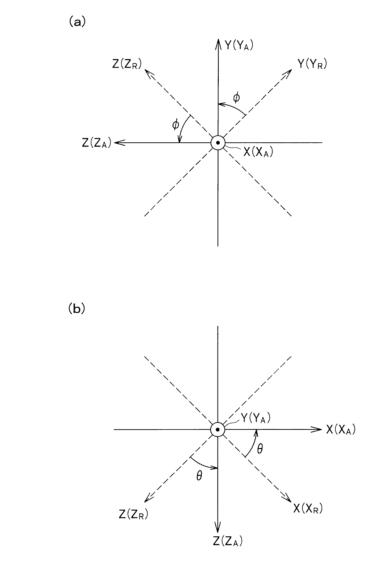
ここで、図4(a)(b)に示すように、相対三次元座標のX軸(XR軸)周りの角度φの回転と、相対三次元座標のY軸(YR軸)周りの角度θの回転と、を第一の三次元座標系に施すことによって、相対三次元座標のXR軸、YR軸及びZ軸(ZR軸)が、第二の三次元座標系のX軸(XA軸)、Y軸(YA軸)及びZ軸(ZA軸)とそれぞれ一致する。なお、φは、XA軸の正側から見て反時計回りが正、時計回りが負である。θは、YA軸の正側から見て反時計回りが正、時計回りが負である。
すなわち、第一の三次元座標系における対応点の第一の三次元座標R=(xR,yR,zR)に、Y軸周りの回転(パン方向の回転)変換と、X軸周りの回転(チルト方向の回転)変換と、を施すことによって、指定点の第二の三次元座標A=(xA,yA,zA)が算出される。本実施形態において、第二の三次元座標系における原点と第一の三次元座標系における原点すなわちO1とは同じ位置であり、回転角度θは、第二の三次元座標系のY軸と第一の三次元座標系のY軸とがなす角度であり、回転角度φは、第二の三次元座標系のX軸と第一の三次元座標系のX軸とがなす角度である。また、本実施形態において、相対三次元座標系におけるX軸は、常に水平方向に保たれているので、Z軸周りの回転変換は不要である。
Here, as shown in FIGS. 4A and 4B, the rotation of the angle φ around the X axis (X R axis) of the relative three-dimensional coordinate and the rotation around the Y axis (Y R axis) of the relative three-dimensional coordinate. by applying rotation and an angle theta, to the first three-dimensional coordinate system, X R-axis relative three-dimensional coordinates, Y R and Z axes (Z R axis), X of the second three-dimensional coordinate system axis (X a-axis), Y axis (Y a-axis) and Z-axis and (Z a axis) coincides respectively. Incidentally, phi, when viewed from the positive side of the X A-axis counterclockwise positive, negative clockwise. θ, when viewed from the positive side of Y A-axis counterclockwise positive, negative clockwise.
That is, the rotation around the Y axis (rotation in the pan direction) and the rotation around the X axis are converted into the first three-dimensional coordinates R = (x R , y R , z R ) of the corresponding points in the first three-dimensional coordinate system. The second three-dimensional coordinates A = (x A , y A , z A ) of the designated point are calculated by performing the rotation (rotation in the tilt direction). In the present embodiment, the origin in the second three-dimensional coordinate system and the origin in the first three-dimensional coordinate system, that is, O 1 are the same position, and the rotation angle θ is equal to the Y-axis of the second three-dimensional coordinate system. The rotation angle φ is an angle formed by the X axis of the second three-dimensional coordinate system and the X axis of the first three-dimensional coordinate system. In the present embodiment, the X-axis in the relative three-dimensional coordinate system is always maintained in the horizontal direction, so that rotation conversion around the Z-axis is not necessary.
≪三次元距離算出部39≫
三次元距離算出部39は、第二の三次元座標算出部38から出力された2つの対応点の第二の三次元座標を取得し、取得された第二の三次元座標に基づいて、2つの対応点間の三次元距離を算出し、画像データ出力部34へ出力する。そして、画像データ出力部34は、算出された三次元距離を表示装置40へ出力して表示装置40に表示させることができる。
≪Three-dimensional
The three-dimensional
<表示装置40>
表示装置40は、三次元座標算出装置30から出力されたパノラマ画像データを用いてパノラマ画像を表示したり、第二撮影画像データ及び第三撮影画像データを用いて第二撮影画像及び第三撮影画像を表示したりするものである。
<
The
<動作例>
続いて、本発明の第一の実施形態に係るパノラマ画像表示システム1Aの動作例について、異なる第一撮影画像に含まれる指定点(始点及び終点)の第二の三次元座標及び三次元距離を算出する場合を例にとり、図1,5〜8を参照して説明する。
<Operation example>
Subsequently, for the operation example of the panoramic image display system 1A according to the first embodiment of the present invention, the second three-dimensional coordinates and the three-dimensional distances of designated points (start point and end point) included in different first captured images are obtained. An example of calculation will be described with reference to FIGS.
まず、制御部13は、駆動部12を回転させることによって、単眼撮影部11a,11b,11cを所望の撮影方向に向け、かかる状態で単眼撮影部11a,11b,11cのシャッタを制御することによって撮影し、撮影画像に関する撮影画像データを三次元座標算出装置30へ出力する。
First, the
続いて、単眼パノラマ画像データ生成部33は、第一の単眼撮影部11aによって撮影された複数の第一撮影画像データを撮影画像データ記憶部31から読み出し、読み出された第一撮影画像データに基づいて単眼パノラマ画像データを生成し、画像データ出力部34へ出力する。画像データ出力部34は、単眼パノラマ画像データを表示装置40へ出力し、表示装置40は、単眼パノラマ画像を表示する。
Subsequently, the monocular panoramic image
かかる状態において、ユーザが入力装置20を操作し、図6(a)に示す第一撮影画像111において、始点としての指定点P11を指定すると、第一撮影画像111における指定点指示が指定点取得部36に入力される(図5のステップS1)。
In this state, when the user operates the
続いて、図6(b)に示すように、対応点検索部61は、第一撮影画像111において指定点P11を中心とする第一領域(例えば、256ピクセル×256ピクセル)A11を設定する(ステップS2)とともに、第一撮影画像111に対応する第二撮影画像112及び第三撮影画像113において、検索対象領域A12を設定する(ステップS3)。ここで、検索対象領域A12は、帯状の領域であって、第二撮影画像112及び第三撮影画像113において単眼撮影部11a〜11cの配列方向全域にわたって設定されており、各単眼撮影部11a〜11cの配列方向(横方向)に直交する方向(縦方向)において第一領域A11を含み得る幅を有する。対応点検索部61は、第一領域A11を用いたマッチングによって、第二撮影画像112及び第三撮影画像113の検索対象領域A12内を検索する(ステップS4)。
Subsequently, as illustrated in FIG. 6B, the corresponding point search unit 61 sets a first area (for example, 256 pixels × 256 pixels) A <b> 11 centered on the designated point P <b> 11 in the first captured image 111 ( Along with step S2), in the second captured
図7(a)に示すように、検索対象領域A12内において第一領域A11に対応する領域A13が発見されると(ステップS5でYes)、対応点検索部61は、第一撮影画像111において指定点P11を中心とする含む第一領域A11よりも狭い第二領域A14(例えば、64ピクセル×64ピクセル)を設定する(ステップS6でNo、かつ、ステップS2)とともに領域A13を検索対象領域に設定する(ステップS3)。対応点検索部61は、第二領域A14を用いたマッチングによって、第二撮影画像112及び第三撮影画像113の第一領域A11に対応する領域A13内を検索する(ステップS4)。
As shown in FIG. 7A, when a region A13 corresponding to the first region A11 is found in the search target region A12 (Yes in step S5), the corresponding point search unit 61 in the first captured image 111 A second region A14 (for example, 64 pixels × 64 pixels) narrower than the first region A11 including the designated point P11 as a center is set (No in step S6 and step S2), and the region A13 is set as a search target region. Set (step S3). The corresponding point search unit 61 searches the area A13 corresponding to the first area A11 of the second photographed
対応点検索部61は、前記動作を第一撮影画像111における指定点P11を中心とする領域のサイズを段階的に小さくして繰り返し(256×256→64×64→8×8)、図7(b)に示すように、指定点P11に対応する対応点P12を決定する(ステップS6)。 The corresponding point search unit 61 repeats the above operation by gradually reducing the size of the region centered on the designated point P11 in the first captured image 111 (256 × 256 → 64 × 64 → 8 × 8), and FIG. As shown in (b), a corresponding point P12 corresponding to the designated point P11 is determined (step S6).
ここで、例えば検索対象領域A12内において第一領域A1に対応する領域A13が発見されなかった場合には(ステップS5でNo)、図8に示すように、対応点検索部61は、第一領域A11を右下領域A11a、左下領域A11b、左上領域A11c、右上領域A11dに四分割し(ステップS11)、分割された各領域A11a〜A11dを用いたマッチングによって、第二撮影画像112及び第三撮影画像113の検索対象領域A12内を検索する(ステップS12)。
Here, for example, when the region A13 corresponding to the first region A1 is not found in the search target region A12 (No in step S5), as shown in FIG. The area A11 is divided into four parts, a lower right area A11a, a lower left area A11b, an upper left area A11c, and an upper right area A11d (step S11). By matching using the divided areas A11a to A11d, the second captured
ここで、分割された各領域A11a〜A11dを用いたマッチングでは、上側の領域A11c,A11dよりも先に下側の領域A11a,A11bを用いることが望ましい。本実施形態では、右下領域A11a→左下領域A11b→左上領域A11c→右上領域A11dの順にマッチングを行い、対応する領域が発見された時点で次のステップに移行する。
実際の撮影画像では、大きい物体の上に小さい物体が設置されていて、下側よりも上側の方が、より奥側が写っているケースが多い。したがって、撮影画像同士の差異が小さい手前側が撮影された可能性が高い下側の領域A11a,A11bを先に用いてマッチングすることによって、マッチングの精度及び速度を両立させることができる。
Here, in the matching using the divided areas A11a to A11d, it is desirable to use the lower areas A11a and A11b before the upper areas A11c and A11d. In the present embodiment, matching is performed in the order of the lower right area A11a → the lower left area A11b → the upper left area A11c → the upper right area A11d, and the process proceeds to the next step when the corresponding area is found.
In actual captured images, there are many cases where a small object is placed on a large object, and the upper side is more visible than the lower side. Therefore, matching and accuracy can be achieved at the same time by using the lower regions A11a and A11b that are likely to have been photographed in the near side where the difference between the photographed images is small.
検索対象領域A12内において各領域A11a〜A11dのいずれかに対応する領域が発見されると(ステップS13でYes)、対応点検索部61は、第一撮影画像111において指定点P11を中心とする含む第一領域A11よりも狭い第二領域A14(例えば、64ピクセル×64ピクセル)を設定する(ステップS6でNo、かつ、ステップS2)とともに、発見された領域に基づいてそれ以外の領域を補完することによって、第一領域A11に対応する領域A13を設定する(ステップS3)。
When a region corresponding to any of the regions A11a to A11d is found in the search target region A12 (Yes in step S13), the corresponding point search unit 61 centers on the designated point P11 in the first captured
なお、かかる動作例において、ステップS4,S5を省略し、ステップS3における検索対象領域設定の後、直ちにステップS11における分割領域設定を行う構成であってもよい。 In this operation example, steps S4 and S5 may be omitted, and the divided region setting in step S11 may be performed immediately after the search target region setting in step S3.
対応点検索部61は、第二撮影画像112及び第三撮影画像113における対応点P12を決定すると、撮影画像データ記憶部31に記憶された、第二撮影画像112における対応点P12の二次元座標(x11,y11)及び第三撮影画像113における対応点P12の二次元座標(x21,y21)を取得し、第一の三次元座標算出部37へ出力する。
When the corresponding point search unit 61 determines the corresponding point P12 in the second captured
続いて、第一の三次元座標算出部37は、下記式に基づいて、始点としての対応点P12の第一の三次元座標RS=(xRS,yRS,zRS)を算出し、第二の三次元座標算出部38へ出力する。
xRS=d(x11+x21)/{2(x11−x21+d)}
yRS=d(y11+y21)/{2(y11−y21+d)}
zRS=−df/{2(x11−x21+d)}
Subsequently, the first three-dimensional coordinate
x RS = d (x 11 + x 21) / {2 (x 11 -x 21 + d)}
y RS = d (y 11 + y 21) / {2 (y 11 -y 21 + d)}
z RS = -df / {2 ( x 11 -x 21 + d)}
続いて、ユーザが入力装置20を操作し、第一撮影画像における終点としての指定点を指定すると、対応点検索部61は、図5のフローを実行することによって、第一撮影画像に対応する第二撮影画像及び第三撮影画像における対応点を決定し、撮影画像データ記憶部31に記憶された、第二撮影画像122における対応点の二次元座標(x12,y12)及び第三撮影画像123における対応点の二次元座標(x22,y22)を取得し、第一の三次元座標算出部37へ出力する。
Subsequently, when the user operates the
続いて、第一の三次元座標算出部37は、下記式に基づいて、終点としての対応点の相対三次元座標RE=(xRE,yRE,zRE)を算出し、第二の三次元座標算出部38へ出力する。
xRE=d(x12+x22)/{2(x12−x22+d)}
yRE=d(y12+y22)/{2(y12−y22+d)}
zRE=−df/{2(x12−x22+d)}
Subsequently, the first three-dimensional coordinate
x RE = d (x 12 + x 22) / {2 (x 12 -x 22 + d)}
y RE = d (y 12 + y 22 ) / {2 (y 12 −y 22 + d)}
z RE = −df / {2 (x 12 −x 22 + d)}
第二の三次元座標算出部38は、下記式に基づいて、始点及び終点の第二の三次元座標AS=(xAS,yAS,zAS)、AE=(xAE,yAE,zAE)を算出し、三次元距離算出部39へ出力する。
The second three-dimensional coordinate calculation unit 38 calculates the second and third second-order coordinates A S = (x AS , y AS , z AS ), A E = (x AE , y AE ) based on the following formula. , Z AE ) and outputs it to the three-dimensional
続いて、三次元距離算出部39は、下記式に基づいて始点及び終点間の三次元距離Dを算出する。これにより、三次元距離が表示装置40に表示される。
D={(xAE−xAS)2+(yAE−yAS)2+(zAE−zAS)2}1/2
Subsequently, the three-dimensional
D = {(x AE -x AS ) 2 + (y AE -y AS) 2 + (z AE -z AS) 2} 1/2
本発明の第一の実施形態に係るパノラマ画像表示システム1Aは、第一撮影画像における指定点に対応する対応点を、第二撮影画像及び第三撮影画像から検索するので、利用者の手動操作によって対応点が決定される場合と比較して、指定点と対応点とのずれを抑制することができる。
また、パノラマ画像表示システム1Aは、パノラマ画像に含まれる全ての画像に共通に使用可能な第二の三次元座標を算出することができる。また、パノラマ画像表示システム1Aは、2つの指定点間の三次元距離を算出することができる。また、パノラマ画像表示システム1Aは、一の撮影方向において、単眼パノラマ画像用の1枚の撮影画像に対応する第一撮影画像データよりも指定点取得用の2枚の撮影画像に対応する第二撮影画像データ及び第三撮影画像データのそれぞれの撮影範囲の方を広く設定しておくことで、第一撮影画像データにおける周縁付近を指定点とした場合であっても、かかる指定点が第二撮影画像データ及び第三撮影画像データの撮影範囲内に確実に入ることとなり、第二の三次元座標及び三次元距離を確実に算出することができる。
Since the panorama image display system 1A according to the first embodiment of the present invention searches the second photographed image and the third photographed image for the corresponding point corresponding to the designated point in the first photographed image, the user's manual operation Compared with the case where the corresponding point is determined by, the shift between the designated point and the corresponding point can be suppressed.
Further, the panoramic image display system 1A can calculate the second three-dimensional coordinates that can be used in common for all the images included in the panoramic image. Further, the panoramic image display system 1A can calculate a three-dimensional distance between two designated points. Further, the panoramic
<第二の実施形態>
続いて、本発明の第二の実施形態に係るパノラマ画像表示システムについて、第一の実施形態に係るパノラマ画像表示システム1Aとの相違点を中心に説明する。
<Second Embodiment>
Next, a panoramic image display system according to the second embodiment of the present invention will be described focusing on differences from the panoramic image display system 1A according to the first embodiment.
図9に示すように、本発明の第二の実施形態に係るパノラマ画像表示システム1Bは、複眼撮影装置10Aに代えて複眼撮影装置10Bを備える。複眼撮影装置10Bは、焦点距離fの第一の単眼撮影部11a及び第二の単眼撮影部11bを備えており、第三の単眼撮影部11cは省略されている。本実施形態における第一の単眼撮影部11aによって撮影された第一撮影画像データは、第一の実施形態における第一撮影画像データ及び第二撮影画像データと同様に用いられ、本実施形態における第二の単眼撮影部11bによって撮影された第二撮影画像データは、第一の実施形態における第三撮影画像データと同様に用いられる。
As shown in FIG. 9, the panoramic image display system 1B according to the second embodiment of the present invention includes a compound
図8に示すように、第一の単眼撮影部11aを第一の三次元座標系における原点に配置し、左側の第一の単眼撮影部11aと右側の第二の単眼撮影部11bとの間隔をdとすると、第一の単眼撮影部11aの第一の三次元座標O1、第二の単眼撮影部11bの第一の三次元座標O2は、以下のようになる。
O1=(0,0,0)
O2=(d,0,0)
As shown in FIG. 8, the first
O 1 = (0, 0, 0)
O 2 = (d, 0, 0)
相対三次元座標R=(xR,yR,zR)に位置する対象物を単眼撮影部11a,11bを用いて撮影し、かかる対象物が第二の単眼撮影部11aによる第一撮影画像の二次元座標N1=(x1,y2)、すなわち第一の三次元座標(x1,y1,−f)に写っており、第二の単眼撮影部11bによる第二撮影画像の二次元座標N2=(x2,y2)、すなわち第一の三次元座標(x2,y2,−f)に写っているとする。
ここで、三角形RO1O2と三角形RN1N2とは相似であるため、以下の関係が成立する。
xR=dx1/(x1−x2)
yR=dy1/(x1−x2)
zR=−df/(x1−x2)
すなわち、第一の三次元座標算出部37は、予め定められた焦点距離f及び間隔dと、撮影画像の二次元座標の値と、を用いることによって、所望の位置の第一の三次元座標R=(xR,yR,zR)を算出することができる。
An object located at relative three-dimensional coordinates R = (x R , y R , z R ) is imaged using the
Here, since the triangle RO 1 O 2 and the triangle RN 1 N 2 are similar, the following relationship is established.
x R = dx 1 / (x 1 -x 2)
y R = dy 1 / (x 1 -x 2)
z R = −df / (x 1 −x 2 )
That is, the first three-dimensional coordinate
<動作例>
続いて、本発明の第二の実施形態に係るパノラマ画像表示システム1Bの動作例について、異なる第一撮影画像に含まれる柱における指定点S,Eの第二の三次元座標及び三次元距離を算出する場合を例にとり、図5,9,11,12を参照して説明する。
<Operation example>
Subsequently, regarding the operation example of the panoramic image display system 1B according to the second embodiment of the present invention, the second three-dimensional coordinates and the three-dimensional distances of the designated points S and E in the pillars included in the different first captured images are obtained. An example of calculation will be described with reference to FIGS.
まず、制御部13は、駆動部12を回転させることによって、単眼撮影部11a,11bを所望の撮影方向に向け、かかる状態で単眼撮影部11a,11bのシャッタを制御することによって撮影し、撮影画像に関する撮影画像データを三次元座標算出装置30へ出力する。
First, the
続いて、単眼パノラマ画像データ生成部33は、第一の単眼撮影部11aによって撮影された複数の第一撮影画像データを撮影画像データ記憶部31から読み出し、読み出された第一撮影画像データに基づいて単眼パノラマ画像データを生成し、画像データ出力部34へ出力する。画像データ出力部34は、単眼パノラマ画像データを表示装置40へ出力し、表示装置40は、単眼パノラマ画像を表示する。
Subsequently, the monocular panoramic image
かかる状態において、ユーザが入力装置20を操作し、図11(a)に示す第一撮影画像121における始点としての指定点P21を指定すると、第一撮影画像121における指定点指示が指定点取得部36に入力される(図5のステップS1)。
In this state, when the user operates the
続いて、図11(b)に示すように、対応点検索部61は、第一撮影画像111において指定点P21を中心とする第一領域(例えば、256ピクセル×256ピクセル)A21を設定する(ステップS2)とともに、第一撮影画像121に対応する第二撮影画像122において、検索対象領域A22を設定する(ステップS3)。ここで、検索対象領域A22は、第二撮影画像112において各単眼撮影部11a,11bの配列方向全域にわたって設定されており、各単眼撮影部11a,11bの配列方向(横方向)に直交する方向(縦方向)において第一領域A21を含み得る幅を有する。対応点検索部61は、第一領域A21を用いたマッチングによって、第二撮影画像122の検索対象領域A22内を検索する(ステップS4)。
Subsequently, as illustrated in FIG. 11B, the corresponding point search unit 61 sets a first area (for example, 256 pixels × 256 pixels) A <b> 21 centered on the designated point P <b> 21 in the first captured image 111 ( Together with step S2), the search target area A22 is set in the second photographed
図12(a)に示すように、検索対象領域A22内において第一領域A21に対応する領域A23が発見されると(ステップS5でYes)、対応点検索部61は、第一撮影画像121において指定点P21を中心とする含む第一領域A21よりも狭い第二領域A24(例えば、64ピクセル×64ピクセル)を設定する(ステップS6でNo、かつ、ステップS2)とともに領域A23を検索対象領域に設定する(ステップS3)。対応点検索部61は、第二領域A24を用いたマッチングによって、第二撮影画像122の第一領域A21に対応する領域A23内を検索する(ステップS4)。
As shown in FIG. 12A, when a region A23 corresponding to the first region A21 is found in the search target region A22 (Yes in step S5), the corresponding point search unit 61 in the first captured image 121 A second area A24 (for example, 64 pixels × 64 pixels) narrower than the first area A21 including the designated point P21 as a center is set (No in step S6 and step S2), and the area A23 is set as a search target area. Set (step S3). The corresponding point search unit 61 searches the area A23 corresponding to the first area A21 of the second photographed
対応点検索部61は、前記動作を第一撮影画像121における指定点P21を中心とする領域のサイズを段階的に小さくして繰り返し(256×256→64×64→8×8)、図11(b)に示すように、指定点P21に対応する対応点P22を決定する(ステップS6)。 The corresponding point search unit 61 repeats the above operation by gradually reducing the size of the region centered on the designated point P21 in the first captured image 121 (256 × 256 → 64 × 64 → 8 × 8), and FIG. As shown in (b), a corresponding point P22 corresponding to the designated point P21 is determined (step S6).
ここで、例えば検索対象領域A22内において第一領域A21に対応する領域A23が発見されなかった場合には(ステップS5でNo)、第一実施形態と同様に、対応点検索部61は、第一領域A21を右下領域、左下領域、左上領域、右上領域に四分割し(ステップS11)、分割された各領域を用いたマッチングによって、第二撮影画像122の検索対象領域A22内を検索する(ステップS12)。
Here, for example, when the area A23 corresponding to the first area A21 is not found in the search target area A22 (No in step S5), the corresponding point search unit 61, as in the first embodiment, The one area A21 is divided into four parts, a lower right area, a lower left area, an upper left area, and an upper right area (step S11), and the search target area A22 of the second captured
検索対象領域A22内において各領域のいずれかに対応する領域が発見されると(ステップS13でYes)、対応点検索部61は、第一撮影画像121において指定点P21を中心とする含む第一領域A21よりも狭い第二領域A24(例えば、64ピクセル×64ピクセル)を設定する(ステップS6でNo、かつ、ステップS2)とともに、発見された領域に基づいてそれ以外の領域を補完することによって、第一領域A21に対応する領域A23を設定する(ステップS3)。
When a region corresponding to any of the regions is found in the search target region A22 (Yes in step S13), the corresponding point search unit 61 includes the first including the designated point P21 in the first captured
対応点検索部61は、第二撮影画像122における対応点P22を決定すると、撮影画像データ記憶部31に記憶された、第二撮影画像122における対応点P22の二次元座標(x21,y21)を取得し、指定点P21の二次元座標(x11,y11)とともに第一の三次元座標算出部37へ出力する
Corresponding point searching unit 61, the second determined the corresponding point P22 in the captured
続いて、第一の三次元座標算出部37は、下記式に基づいて、始点としての指定点P21(対応点P22)の第一の三次元座標RS=(xRS,yRS,zRS)を算出し、第二の三次元座標算出部38へ出力する。
xRS=dx11/(x11−x21)
yRS=dy11/(x11−x21)
zRS=−df/(x11−x21)
Subsequently, the first three-dimensional coordinate
x RS = dx 11 / (x 11 -x 21)
y RS = dy 11 / (x 11 -x 21)
z RS = -df / (x 11 -x 21)
続いて、ユーザが入力装置20を操作し、第一撮影画像における終点としての指定点を指定すると、対応点検索部61は、図5のフローを実行することによって、第一撮影画像に対応する第二撮影画像における対応点を決定し、撮影画像データ記憶部31に記憶された、第二撮影画像における対応点の二次元座標(x22,y22)を取得し、指定点P21の二次元座標(x11,y11)とともに第一の三次元座標算出部37へ出力する。
Subsequently, when the user operates the
続いて、第一の三次元座標算出部37は、下記式に基づいて、終点としての指定点(対応点)の相対三次元座標RE=(xRE,yRE,zRE)を算出し、第二の三次元座標算出部38へ出力する。
xRE=dx12/(x12−x22)
yRE=dy12/(x12−x22)
zRE=−df/(x12−x22)
Subsequently, the first three-dimensional coordinate
x RE = dx 12 / (x 12 -x 22)
y RE = dy 12 / (x 12 −x 22 )
z RE = −df / (x 12 −x 22 )
第二の三次元座標算出部38は、下記式に基づいて、指定及び終点の第二の三次元座標AS=(xAS,yAS,zAS)、AE=(xAE,yAE,zAE)を算出し、三次元距離算出部39へ出力する。
The second three-dimensional coordinate calculation unit 38, based on the following formula, designates and finishes the second three-dimensional coordinates A S = (x AS , y AS , z AS ), A E = (x AE , y AE). , Z AE ) and outputs it to the three-dimensional
続いて、三次元距離算出部39は、下記式に基づいて始点及び終点間の三次元距離Dを算出する。これにより、三次元距離が表示装置40に表示される。
D={(xAE−xAS)2+(yAE−yAS)2+(zAE−zAS)2}1/2
Subsequently, the three-dimensional
D = {(x AE -x AS ) 2 + (y AE -y AS) 2 + (z AE -z AS) 2} 1/2
本発明の第二の実施形態に係るパノラマ画像表示システム1Bは、パノラマ画像表示システム1Aと比べて単眼撮影部を一つ省略することができる。 The panoramic image display system 1B according to the second embodiment of the present invention can omit one monocular photographing unit as compared with the panoramic image display system 1A.
以上、本発明の実施形態について説明したが、本発明は前記実施形態に限定されず、本発明の要旨を逸脱しない範囲で適宜設計変更可能である。例えば、ステップS11における領域の分割数は4に限定されない。また、算出された第二の三次元座標及び三次元距離をユーザに通知する手法は、表示装置40に表示させることに限定されず、通知部としてのスピーカに発話させる構成であってもよい。また、Z軸周りの回転(回転角度ψ)も考慮した場合には、第二の三次元座標は、下記式によって算出可能である。
As mentioned above, although embodiment of this invention was described, this invention is not limited to the said embodiment, A design change is possible suitably in the range which does not deviate from the summary of this invention. For example, the number of area divisions in step S11 is not limited to four. Further, the method of notifying the user of the calculated second three-dimensional coordinates and the three-dimensional distance is not limited to display on the
また、本発明では第一の三次元座標系及び第二の三次元座標系として右手座標系を採用したが、左手座標系を採用することも可能である。 In the present invention, the right-handed coordinate system is adopted as the first three-dimensional coordinate system and the second three-dimensional coordinate system, but a left-handed coordinate system can also be adopted.
1A,1B パノラマ画像表示システム
30 三次元座標算出装置(画像検索装置)
31 画像データ記憶部
33 単眼パノラマ画像データ生成部
34 画像データ出力部
35 画像データ指定取得部
36 指定点取得部
37 第一の三次元座標算出部
38 第二の三次元座標算出部
39 三次元距離算出部
51 対応点検索部
1A, 1B Panoramic
31 Image
Claims (2)
前記第一画像データを表示装置へ出力する画像データ出力部と、
ユーザによる入力装置の操作に応じて、前記第一画像データにおける指定点を取得する指定点取得部と、
前記第一画像データにおける前記指定点周辺の画像データを用いた画像マッチングによって、前記第二画像データ及び前記第三画像データのぞれぞれにおいて前記指定点に対応する対応点を検索する対応点検索部と、
を備え、
前記第一撮影装置、前記第二撮影装置及び前記第三撮影装置は、直線上に配列されて同一方向を撮影しており、
前記対応点検索部は、
前記第二画像データ及び前記第三画像データにおいて前記第一撮影装置、前記第二撮影装置及び前記第三撮影装置の配列方向とは直交する方向に所定幅を有する検索対象領域を設定し、前記第一画像データにおける前記指定点を含む第一領域のデータを用いて前記第二画像データ及び前記第三画像データの前記検索対象領域内をそれぞれ検索し、
前記検索対象領域内において前記第一領域に対応する領域が発見された場合には、前記第一画像データにおける前記指定点を含む前記第一領域よりも狭い第二領域のデータを用いて前記第二画像データ及び第三画像データの前記第一領域に対応する領域をそれぞれ検索し、
前記検索対象領域内において前記第一領域に対応する領域が発見されなかった場合には、前記第一領域を分割した領域を用いて前記第二画像データ及び前記第三画像データの前記第一領域に対応する領域を検索する
ことを特徴とする記載の画像検索装置。 First image data photographed by the first photographing device, second image data photographed by the second photographing device separated from the first photographing device by a predetermined distance, and third image separated by a predetermined distance from the first photographing device. An image data storage unit that stores the third image data captured by the imaging device in association with each other;
An image data output unit for outputting the first image data to a display device;
A designated point obtaining unit for obtaining a designated point in the first image data in accordance with an operation of the input device by a user;
Corresponding points for searching corresponding points corresponding to the designated points in the second image data and the third image data by image matching using the image data around the designated points in the first image data. A search section;
Equipped with a,
The first photographing device, the second photographing device, and the third photographing device are arranged on a straight line and photograph the same direction,
The corresponding point search unit
In the second image data and the third image data, a search target area having a predetermined width is set in a direction orthogonal to the arrangement direction of the first imaging device, the second imaging device, and the third imaging device, and Search each of the search target areas of the second image data and the third image data using data of the first area including the designated point in the first image data,
When an area corresponding to the first area is found in the search target area, the second area data narrower than the first area including the designated point in the first image data is used. Search the areas corresponding to the first area of the second image data and the third image data,
If no region corresponding to the first region is found in the search target region, the first region of the second image data and the third image data using the region obtained by dividing the first region The image search apparatus according to claim 1, wherein an area corresponding to the image is searched.
前記第一画像データを表示装置へ出力する画像データ出力部と、
ユーザによる入力装置の操作に応じて、前記第一画像データにおける指定点を取得する指定点取得部と、
前記第一画像データにおける前記指定点周辺の画像データを用いた画像マッチングによって、前記第二画像データにおいて前記指定点に対応する対応点を検索する対応点検索部と、
を備え、
前記第一撮影装置及び前記第二撮影装置は、同一方向を撮影しており、
前記対応点検索部は、
前記第二画像データにおいて前記第一撮影装置及び前記第二撮影装置の配列方向とは直交する方向に所定幅を有する検索対象領域を設定し、前記第一画像データにおける前記指定点を含む第一領域のデータを用いて前記第二画像データの前記検索対象領域内を検索し、
前記検索対象領域内において前記第一領域に対応する領域が発見された場合には、前記第一画像データにおける前記指定点を含む前記第一領域よりも狭い第二領域のデータを用いて前記第二画像データの前記第一領域に対応する領域を検索し、
前記検索対象領域内において前記第一領域に対応する領域が発見されなかった場合には、前記第一領域を分割した領域を用いて前記第二画像データの前記第一領域に対応する領域を検索する
ことを特徴とする画像検索装置。 An image data storage unit that stores the first image data captured by the first image capturing device and the second image data captured by the second image capturing device spaced apart from the first image capturing device by a predetermined distance;
An image data output unit for outputting the first image data to a display device;
A designated point obtaining unit for obtaining a designated point in the first image data in accordance with an operation of the input device by a user;
A corresponding point search unit for searching for a corresponding point corresponding to the specified point in the second image data by image matching using image data around the specified point in the first image data;
Equipped with a,
The first photographing device and the second photographing device are photographing the same direction,
The corresponding point search unit
In the second image data, a search target area having a predetermined width is set in a direction orthogonal to the arrangement direction of the first imaging device and the second imaging device, and the first image data includes the designated point in the first image data. Search within the search target area of the second image data using area data,
When an area corresponding to the first area is found in the search target area, the second area data narrower than the first area including the designated point in the first image data is used. Search the area corresponding to the first area of the two image data,
If no area corresponding to the first area is found in the search target area, an area corresponding to the first area of the second image data is searched using an area obtained by dividing the first area. An image search apparatus characterized by:
Priority Applications (1)
| Application Number | Priority Date | Filing Date | Title |
|---|---|---|---|
| JP2013162393A JP6116094B2 (en) | 2013-08-05 | 2013-08-05 | Image search device |
Applications Claiming Priority (1)
| Application Number | Priority Date | Filing Date | Title |
|---|---|---|---|
| JP2013162393A JP6116094B2 (en) | 2013-08-05 | 2013-08-05 | Image search device |
Publications (2)
| Publication Number | Publication Date |
|---|---|
| JP2015032198A JP2015032198A (en) | 2015-02-16 |
| JP6116094B2 true JP6116094B2 (en) | 2017-04-19 |
Family
ID=52517444
Family Applications (1)
| Application Number | Title | Priority Date | Filing Date |
|---|---|---|---|
| JP2013162393A Active JP6116094B2 (en) | 2013-08-05 | 2013-08-05 | Image search device |
Country Status (1)
| Country | Link |
|---|---|
| JP (1) | JP6116094B2 (en) |
Family Cites Families (5)
| Publication number | Priority date | Publication date | Assignee | Title |
|---|---|---|---|---|
| JPH10149424A (en) * | 1996-11-19 | 1998-06-02 | Mitsubishi Electric Corp | Topographic map creation device |
| JP3077745B2 (en) * | 1997-07-31 | 2000-08-14 | 日本電気株式会社 | Data processing method and apparatus, information storage medium |
| JP2000137815A (en) * | 1998-11-02 | 2000-05-16 | Gen Tec:Kk | New viewpoint image generation method |
| JP2004234423A (en) * | 2003-01-31 | 2004-08-19 | Seiko Epson Corp | Stereo image processing method, stereo image processing device, and stereo image processing program |
| JP2006113832A (en) * | 2004-10-15 | 2006-04-27 | Canon Inc | Stereo image processing apparatus and program |
-
2013
- 2013-08-05 JP JP2013162393A patent/JP6116094B2/en active Active
Also Published As
| Publication number | Publication date |
|---|---|
| JP2015032198A (en) | 2015-02-16 |
Similar Documents
| Publication | Publication Date | Title |
|---|---|---|
| JP4508049B2 (en) | 360 ° image capturing device | |
| US9667864B2 (en) | Image conversion apparatus, camera, image conversion method, and storage medium with program stored therein | |
| WO2018068719A1 (en) | Image stitching method and apparatus | |
| JP2017112602A (en) | Image calibrating, stitching and depth rebuilding method of panoramic fish-eye camera and system thereof | |
| CN109920004B (en) | Image processing method, device, calibration object combination, terminal equipment and calibration system | |
| JP6615545B2 (en) | Image processing apparatus, image processing method, and image processing program | |
| JP5070435B1 (en) | Three-dimensional relative coordinate measuring apparatus and method | |
| WO2019183845A1 (en) | Pan-tilt device control method, apparatus and system, computer storage medium and unmanned aerial vehicle | |
| JPWO2021200432A5 (en) | Shooting method, shooting instruction method, shooting device and shooting instruction device | |
| JP2022105568A (en) | System and method for displaying 3d tour comparison | |
| CN113034347A (en) | Oblique photographic image processing method, device, processing equipment and storage medium | |
| US20140168375A1 (en) | Image conversion device, camera, video system, image conversion method and recording medium recording a program | |
| JP5882153B2 (en) | Three-dimensional coordinate calculation device | |
| JP2011146762A (en) | Solid model generator | |
| JP5514062B2 (en) | Electronic device, imaging screen display method with information, and program | |
| JP2020129823A (en) | Image capturing apparatus, image capturing system, image processing method, information processing apparatus, and program | |
| JP2014127839A (en) | Image synthesizing apparatus and image synthesizing method | |
| JP5648159B2 (en) | Three-dimensional relative coordinate measuring apparatus and method | |
| JP6116094B2 (en) | Image search device | |
| JP4680033B2 (en) | Monitoring system and monitoring device | |
| JP2016224015A (en) | Three-dimensional position measurement method, surveying method, three-dimensional position measurement apparatus, and three-dimensional position measurement program | |
| JP2005275789A (en) | 3D structure extraction method | |
| JP5885974B2 (en) | Corresponding point setting method, corresponding point setting device, and corresponding point setting program for aerial photo image data | |
| JP6579706B2 (en) | Image processing apparatus, image processing method, and image processing program | |
| JP2014160405A (en) | Photographic position determination device, program and method |
Legal Events
| Date | Code | Title | Description |
|---|---|---|---|
| A621 | Written request for application examination |
Free format text: JAPANESE INTERMEDIATE CODE: A621 Effective date: 20160304 |
|
| RD02 | Notification of acceptance of power of attorney |
Free format text: JAPANESE INTERMEDIATE CODE: A7422 Effective date: 20160506 |
|
| A977 | Report on retrieval |
Free format text: JAPANESE INTERMEDIATE CODE: A971007 Effective date: 20161216 |
|
| A131 | Notification of reasons for refusal |
Free format text: JAPANESE INTERMEDIATE CODE: A131 Effective date: 20161220 |
|
| A521 | Request for written amendment filed |
Free format text: JAPANESE INTERMEDIATE CODE: A523 Effective date: 20170220 |
|
| TRDD | Decision of grant or rejection written | ||
| A01 | Written decision to grant a patent or to grant a registration (utility model) |
Free format text: JAPANESE INTERMEDIATE CODE: A01 Effective date: 20170307 |
|
| A61 | First payment of annual fees (during grant procedure) |
Free format text: JAPANESE INTERMEDIATE CODE: A61 Effective date: 20170320 |
|
| R150 | Certificate of patent or registration of utility model |
Ref document number: 6116094 Country of ref document: JP Free format text: JAPANESE INTERMEDIATE CODE: R150 |
|
| R250 | Receipt of annual fees |
Free format text: JAPANESE INTERMEDIATE CODE: R250 |
|
| R250 | Receipt of annual fees |
Free format text: JAPANESE INTERMEDIATE CODE: R250 |
|
| R250 | Receipt of annual fees |
Free format text: JAPANESE INTERMEDIATE CODE: R250 |
|
| R250 | Receipt of annual fees |
Free format text: JAPANESE INTERMEDIATE CODE: R250 |
|
| R250 | Receipt of annual fees |
Free format text: JAPANESE INTERMEDIATE CODE: R250 |