JP6112222B2 - Frequency characteristic measurement method - Google Patents
Frequency characteristic measurement method Download PDFInfo
- Publication number
- JP6112222B2 JP6112222B2 JP2015547738A JP2015547738A JP6112222B2 JP 6112222 B2 JP6112222 B2 JP 6112222B2 JP 2015547738 A JP2015547738 A JP 2015547738A JP 2015547738 A JP2015547738 A JP 2015547738A JP 6112222 B2 JP6112222 B2 JP 6112222B2
- Authority
- JP
- Japan
- Prior art keywords
- electrode
- measurement
- power transmission
- frequency characteristic
- power
- Prior art date
- Legal status (The legal status is an assumption and is not a legal conclusion. Google has not performed a legal analysis and makes no representation as to the accuracy of the status listed.)
- Active
Links
- 238000000691 measurement method Methods 0.000 title claims description 34
- 238000005259 measurement Methods 0.000 claims description 215
- 230000005540 biological transmission Effects 0.000 claims description 202
- 239000003990 capacitor Substances 0.000 claims description 57
- 238000000034 method Methods 0.000 claims description 47
- 230000005684 electric field Effects 0.000 claims description 15
- 238000010168 coupling process Methods 0.000 claims description 12
- 230000008878 coupling Effects 0.000 claims description 11
- 238000005859 coupling reaction Methods 0.000 claims description 11
- 238000010586 diagram Methods 0.000 description 19
- 238000009499 grossing Methods 0.000 description 3
- 230000000903 blocking effect Effects 0.000 description 2
- 239000006185 dispersion Substances 0.000 description 2
- 230000005855 radiation Effects 0.000 description 2
- 238000006243 chemical reaction Methods 0.000 description 1
- 239000002131 composite material Substances 0.000 description 1
- 230000005284 excitation Effects 0.000 description 1
- 230000003071 parasitic effect Effects 0.000 description 1
- 229920001690 polydopamine Polymers 0.000 description 1
Images


Classifications
-
- H—ELECTRICITY
- H02—GENERATION; CONVERSION OR DISTRIBUTION OF ELECTRIC POWER
- H02J—CIRCUIT ARRANGEMENTS OR SYSTEMS FOR SUPPLYING OR DISTRIBUTING ELECTRIC POWER; SYSTEMS FOR STORING ELECTRIC ENERGY
- H02J50/00—Circuit arrangements or systems for wireless supply or distribution of electric power
- H02J50/05—Circuit arrangements or systems for wireless supply or distribution of electric power using capacitive coupling
-
- G—PHYSICS
- G01—MEASURING; TESTING
- G01R—MEASURING ELECTRIC VARIABLES; MEASURING MAGNETIC VARIABLES
- G01R23/00—Arrangements for measuring frequencies; Arrangements for analysing frequency spectra
- G01R23/02—Arrangements for measuring frequency, e.g. pulse repetition rate; Arrangements for measuring period of current or voltage
- G01R23/04—Arrangements for measuring frequency, e.g. pulse repetition rate; Arrangements for measuring period of current or voltage adapted for measuring in circuits having distributed constants
-
- G—PHYSICS
- G01—MEASURING; TESTING
- G01R—MEASURING ELECTRIC VARIABLES; MEASURING MAGNETIC VARIABLES
- G01R23/00—Arrangements for measuring frequencies; Arrangements for analysing frequency spectra
- G01R23/16—Spectrum analysis; Fourier analysis
-
- G—PHYSICS
- G01—MEASURING; TESTING
- G01R—MEASURING ELECTRIC VARIABLES; MEASURING MAGNETIC VARIABLES
- G01R29/00—Arrangements for measuring or indicating electric quantities not covered by groups G01R19/00 - G01R27/00
- G01R29/08—Measuring electromagnetic field characteristics
- G01R29/0864—Measuring electromagnetic field characteristics characterised by constructional or functional features
- G01R29/0878—Sensors; antennas; probes; detectors
-
- H—ELECTRICITY
- H02—GENERATION; CONVERSION OR DISTRIBUTION OF ELECTRIC POWER
- H02J—CIRCUIT ARRANGEMENTS OR SYSTEMS FOR SUPPLYING OR DISTRIBUTING ELECTRIC POWER; SYSTEMS FOR STORING ELECTRIC ENERGY
- H02J7/00—Circuit arrangements for charging or depolarising batteries or for supplying loads from batteries
- H02J7/34—Parallel operation in networks using both storage and other DC sources, e.g. providing buffering
- H02J7/342—The other DC source being a battery actively interacting with the first one, i.e. battery to battery charging
-
- H—ELECTRICITY
- H02—GENERATION; CONVERSION OR DISTRIBUTION OF ELECTRIC POWER
- H02J—CIRCUIT ARRANGEMENTS OR SYSTEMS FOR SUPPLYING OR DISTRIBUTING ELECTRIC POWER; SYSTEMS FOR STORING ELECTRIC ENERGY
- H02J50/00—Circuit arrangements or systems for wireless supply or distribution of electric power
- H02J50/70—Circuit arrangements or systems for wireless supply or distribution of electric power involving the reduction of electric, magnetic or electromagnetic leakage fields
Landscapes
- Physics & Mathematics (AREA)
- Engineering & Computer Science (AREA)
- General Physics & Mathematics (AREA)
- Power Engineering (AREA)
- Computer Networks & Wireless Communication (AREA)
- Mathematical Physics (AREA)
- Electromagnetism (AREA)
- Measurement Of Resistance Or Impedance (AREA)
Description
本発明は、電界結合方式を利用して、送電装置から受電装置へ電力伝送する電力伝送システムにおける、送電装置、及び受電装置それぞれの周波数特性を測定する周波数特性測定方法に関する。 The present invention relates to a power transmission system in a power transmission system that transmits power from a power transmission device to a power reception device using an electric field coupling method, and a frequency characteristic measurement method that measures frequency characteristics of each of the power reception devices.
電界結合方式のワイヤレス電力伝送システムとして、例えば、特許文献1に記載されているように、送電装置のアクティブ電極と受電装置のアクティブ電極とを対向させ、その二つの電極間に強い電場を形成して電極同士を電界結合させ、その電界結合によって、送電装置から受電装置へ電力伝送するシステムが知られている。この電界結合方式のワイヤレス電力伝送システムは、送電装置および受電装置間での高い伝送効率の電力伝送を可能としている。また、送電装置に対して受電装置を載置する位置の自由度が比較的高く、さらに、装置の小型化及び薄型化を可能としている。
As an electric field coupling type wireless power transmission system, for example, as described in
特許文献1に記載のワイヤレス電力伝送システムにおいて、電力伝送の効率を高めるため、送電装置、及び受電装置それぞれに形成される共振回路の共振特性を所望の特性に合わせこむ必要がある。従来、共振特性を所望の特性に合わせこむために、送電装置に受電装置を載置した状態で、共振特性を測定し、その状態で各装置を設計していた。しかしながら、このような場合、送電装置と受電装置との両方の特性が複合化された特性しか測定できない。このため、それぞれ別々に設定を行った場合に比べて、個々の装置の共振特性のばらつきが大きくなり、伝送効率のばらつきも大きくなるという問題がある。
In the wireless power transmission system described in
そこで、本発明の目的は、ワイヤレス電力伝送システムの送電装置、及び受電装置それぞれの周波数特性を個別に測定できる周波数特性測定方法を提供することにある。 Accordingly, an object of the present invention is to provide a frequency characteristic measurement method capable of individually measuring the frequency characteristics of the power transmission device and the power reception device of the wireless power transmission system.
本発明は、高周波発生回路と、前記高周波発生回路に接続された送電共振回路と、前記送電共振回路の出力側に接続された第1の電極及び第2の電極とを有する送電装置と、 前記第1の電極と間隙を置いて対向する第3の電極、及び、前記第2の電極と接触する、または、間隙を置いて対向する第4の電極と、前記第3の電極、及び前記第4の電極に接続される受電共振回路とを有する受電装置と、を備え、前記送電装置から受電装置へ電界結合により電力伝送するワイヤレス電力伝送システムにおける前記送電装置の周波数特性を測定する周波数特性測定方法において、前記第1の電極と間隙を置いて対向する測定用第1の電極、及び、前記第2の電極と接触する、または、間隙を置いて対向する測定用第2の電極を有し、前記測定用第1の電極、及び前記測定用第2の電極を接続した送電側測定用治具を、前記送電装置に対し設置して、前記高周波発生回路と前記送電共振回路との間で、前記送電共振回路の周波数特性を測定することを特徴とする。 The present invention includes a high-frequency generation circuit, a power transmission resonance circuit connected to the high-frequency generation circuit, and a power transmission device having a first electrode and a second electrode connected to an output side of the power transmission resonance circuit, The third electrode that faces the first electrode with a gap and the fourth electrode that contacts the second electrode or faces the gap with the gap, the third electrode, and the second electrode A power receiving device having a power receiving resonance circuit connected to the four electrodes, and measuring frequency characteristics of the power transmitting device in a wireless power transmission system for transmitting power from the power transmitting device to the power receiving device by electric field coupling. In the method, the first electrode for measurement is opposed to the first electrode with a gap, and the second electrode for measurement is in contact with the second electrode or opposed to the second electrode with a gap. , For measurement And a power transmission side measuring jig connected to the second electrode for measurement with respect to the power transmission device, and between the high frequency generation circuit and the power transmission resonance circuit, the power transmission resonance circuit It is characterized by measuring frequency characteristics.
この測定方法では、送電側測定用治具を用いることで、送電装置側の共振回路が、受電装置側の共振回路と結合しない状態で周波数測定できる、すなわち、送電装置側の共振回路のみに関して、周波数特性のみを測定できる。このため、その測定結果に基づいて、送電装置を回路設計した場合、受電装置の回路構成とは関係なく、送電装置を回路設計できるため、汎用性の高い送電装置を製造できる。 In this measurement method, by using the power transmission side measurement jig, the frequency measurement can be performed in a state where the resonance circuit on the power transmission device side is not coupled to the resonance circuit on the power reception device side, that is, only the resonance circuit on the power transmission device side. Only frequency characteristics can be measured. For this reason, when the power transmission device is designed based on the measurement result, the power transmission device can be designed regardless of the circuit configuration of the power reception device, and thus a highly versatile power transmission device can be manufactured.
前記周波数特性は、前記送電共振回路の共振周波数、及びQ値であることが好ましい。 The frequency characteristic is preferably a resonance frequency and a Q value of the power transmission resonance circuit.
この測定方法により、送電共振回路の共振周波数、及びQ値が測定により得られるため、その結果に基づいて、回路設計を行うことで、電力伝送効率が高い、汎用性のある送電装置を製造できる。 By this measurement method, the resonance frequency and Q value of the power transmission resonance circuit can be obtained by measurement. Based on the result, circuit design is performed, and a power transmission device with high power transmission efficiency and versatility can be manufactured. .
前記測定方法では、前記測定用第1の電極と、前記測定用第2の電極とを短絡した状態で、周波数特性を測定することが好ましい。 In the measurement method, it is preferable to measure frequency characteristics in a state where the first electrode for measurement and the second electrode for measurement are short-circuited.
この測定方法では、送電側測定用治具が簡易な構成で実現でき、送電共振回路の周波数特性のみを測定できる。 In this measurement method, the power transmission side measurement jig can be realized with a simple configuration, and only the frequency characteristic of the power transmission resonance circuit can be measured.
前記測定方法では、前記測定用第1の電極と、前記測定用第2の電極とを容量を介して接続した状態で、周波数特性を測定することが好ましい。 In the measurement method, it is preferable to measure frequency characteristics in a state where the first electrode for measurement and the second electrode for measurement are connected via a capacitor.
この測定方法では、送電共振回路の共振条件を調整(補正)できるため、実際の使用時下に近い状況での周波数特性の測定結果が得られる。 In this measurement method, the resonance condition of the power transmission resonance circuit can be adjusted (corrected), so that a measurement result of the frequency characteristic in a situation close to that during actual use can be obtained.
前記測定方法では、前記送電装置に設けられ、前記送電装置のグランド電位に接続された送電側グランド電極と、前記送電側測定用治具に設けられ、前記送電装置のグランド電位に接続された受電側グランド電極とで、前記第1の電極、前記第2の電極、前記測定用第1の電極、及び前記測定用第2の電極を挟み込んだ状態で、周波数特性を測定することが好ましい。 In the measurement method, the power transmission side ground electrode provided in the power transmission device and connected to the ground potential of the power transmission device, and the power reception side provided in the power transmission side measurement jig and connected to the ground potential of the power transmission device. It is preferable that the frequency characteristic is measured in a state where the first electrode, the second electrode, the first electrode for measurement, and the second electrode for measurement are sandwiched between the side ground electrode.
この測定方法では、各電極をグランド電極で挟み込むことで、実際の使用時下に近い状況での周波数特性の測定結果が得られる。 In this measurement method, each electrode is sandwiched between ground electrodes, so that a measurement result of frequency characteristics in a situation close to that in actual use can be obtained.
本発明は、高周波発生回路と、前記高周波発生回路に接続された送電共振回路と、前記送電共振回路の出力側に接続された第1の電極及び第2の電極とを有する送電装置と、前記第1の電極と間隙を置いて対向する第3の電極、及び、前記第2の電極と接触する、または、間隙を置いて対向する第4の電極と、前記第3の電極、及び前記第4の電極が入力側に接続された受電共振回路と、前記受電共振回路の出力側に接続された整流回路とを有する受電装置と、を備え、前記送電装置から受電装置へ電界結合により電力伝送するワイヤレス電力伝送システムにおける前記受電装置の周波数特性を測定する周波数特性測定方法において、前記第3の電極と間隙を置いて対向する測定用第3の電極、及び、前記第4の電極と接触する、または、間隙を置いて対向する測定用第4の電極を有し、前記測定用第3の電極、及び前記測定用第4の電極を接続した受電側測定用治具を、前記受電装置に対し設置して、前記受電共振回路と前記整流回路との間で、前記受電共振回路の周波数特性を測定する、ことを特徴とする。 The present invention includes a high frequency generation circuit, a power transmission resonance circuit connected to the high frequency generation circuit, and a power transmission device having a first electrode and a second electrode connected to an output side of the power transmission resonance circuit, The third electrode that faces the first electrode with a gap and the fourth electrode that contacts the second electrode or faces the gap with the gap, the third electrode, and the second electrode A power receiving device having a power receiving resonance circuit having four electrodes connected to an input side and a rectifier circuit connected to an output side of the power receiving resonance circuit, and transmitting electric power from the power transmitting device to the power receiving device by electric field coupling In the frequency characteristic measurement method for measuring the frequency characteristic of the power receiving device in the wireless power transmission system, the third electrode for measurement facing the third electrode with a gap is in contact with the fourth electrode. Or between A power-receiving-side measuring jig having the fourth electrode for measurement facing and having the third electrode for measurement and the fourth electrode for measurement connected to the power receiving device; The frequency characteristic of the power receiving resonant circuit is measured between the power receiving resonant circuit and the rectifier circuit.
この測定方法では、受電側測定用治具を用いることで、受電装置側の共振回路が、送電装置側の共振回路と結合しない状態で周波数測定できる、すなわち、受電装置側の共振回路のみに関して、周波数特性のみを測定できる。このため、その測定結果に基づいて、受電装置を回路設計した場合、送電装置の回路構成とは関係なく、受電装置を回路設計できるため、汎用性の高い受電装置を製造できる。 In this measurement method, by using the power receiving side measurement jig, the frequency measurement can be performed in a state where the resonance circuit on the power reception device side is not coupled with the resonance circuit on the power transmission device side, that is, only the resonance circuit on the power reception device side. Only frequency characteristics can be measured. For this reason, when the circuit of the power receiving device is designed based on the measurement result, the power receiving device can be designed regardless of the circuit configuration of the power transmitting device, and thus a highly versatile power receiving device can be manufactured.
前記周波数特性は、前記受電共振回路の共振周波数、及びQ値であることが好ましい。 この測定方法により、受電共振回路の共振周波数、及びQ値が測定により得られるため、その結果に基づいて、回路設計を行うことで、電力伝送効率が高い、汎用性のある受電装置を製造できる。 The frequency characteristic is preferably a resonance frequency and a Q value of the power receiving resonance circuit. By this measurement method, the resonance frequency and the Q value of the power receiving resonance circuit can be obtained by measurement. Based on the result, circuit design is performed, and thus a power receiving device with high power transmission efficiency and versatility can be manufactured. .
前記測定方法では、前記測定用第3の電極と、前記測定用第4の電極とを短絡した状態で、周波数特性を測定することが好ましい。 In the measurement method, it is preferable to measure frequency characteristics in a state where the third electrode for measurement and the fourth electrode for measurement are short-circuited.
この測定方法では、受電側測定用治具が簡易な構成で実現でき、受電共振回路の周波数特性のみを測定できる。 In this measurement method, the power receiving side measuring jig can be realized with a simple configuration, and only the frequency characteristic of the power receiving resonance circuit can be measured.
前記測定方法では、前記測定用第3の電極と、前記測定用第4の電極とを容量を介して接続した状態で、周波数特性を測定することが好ましい。 In the measurement method, it is preferable that the frequency characteristic is measured in a state where the third electrode for measurement and the fourth electrode for measurement are connected via a capacitor.
この測定方法では、受電共振回路の共振条件を調整(補正)できるため、実際の使用時下に近い状況での周波数特性の測定結果が得られる。 In this measurement method, the resonance condition of the power receiving resonance circuit can be adjusted (corrected), so that a measurement result of the frequency characteristic in a situation close to that in actual use can be obtained.
前記測定方法では、前記受電側測定治具に設けられ、前記送電装置のグランド電位に接続された送電側グランド電極と、前記受電装置に設けられ、前記送電装置のグランド電位に接続された受電側グランド電極とで、前記第3の電極、前記第4の電極、前記測定用第3の電極、及び、前記測定用第4の電極を挟み込んだ状態で、周波数特性を測定することが好ましい。 In the measurement method, a power transmission side ground electrode provided in the power reception side measurement jig and connected to the ground potential of the power transmission device, and a power reception side provided in the power reception device and connected to the ground potential of the power transmission device It is preferable to measure frequency characteristics in a state where the third electrode, the fourth electrode, the third electrode for measurement, and the fourth electrode for measurement are sandwiched between the ground electrode.
この測定方法では、各電極をグランド電極で挟み込むことで、実際の使用時下に近い状況での周波数特性の測定結果が得られる。 In this measurement method, each electrode is sandwiched between ground electrodes, so that a measurement result of frequency characteristics in a situation close to that in actual use can be obtained.
本発明によれば、送電装置の共振回路、又は、受電装置の共振回路のインピーダンスを個別に測定できる。このため、その測定結果に基づいて、受電装置、又は送電装置を回路設計した場合、測定時に用いた送電装置、又は受電装置の回路構成とは関係なく、受電装置、又は送電装置を回路設計できるため、汎用性の高い受電装置、又は送電装置を製造できる。 ADVANTAGE OF THE INVENTION According to this invention, the impedance of the resonance circuit of a power transmission apparatus or the resonance circuit of a power receiving apparatus can be measured separately. For this reason, when the power receiving device or the power transmitting device is designed based on the measurement result, the power receiving device or the power transmitting device can be designed regardless of the circuit configuration of the power transmitting device or the power receiving device used at the time of measurement. Therefore, a highly versatile power receiving device or power transmitting device can be manufactured.
(実施形態1)
図1は、本実施形態に係るワイヤレス電力伝送システムの回路図である。(Embodiment 1)
FIG. 1 is a circuit diagram of a wireless power transmission system according to the present embodiment.
ワイヤレス電力伝送システム300は送電装置101と受電装置201とを備えている。受電装置201は負荷回路RLを備えている。この負荷回路RLは二次電池と充電回路を含むバッテリモジュールである。そして、受電装置201は、その二次電池を備えた、例えば携帯電子機器である。携帯電子機器としては携帯電話機、PDA、携帯音楽プレーヤ、ノート型PC、デジタルカメラなどが挙げられる。送電装置101に受電装置201が載置されると、その状態で、送電装置101は、受電装置201へ電力を伝送する。そして、受電装置201は、二次電池を充電する。
The wireless
送電装置101は、直流電圧源Vinを備えている。直流電圧源Vinは、ACアダプタにより変換される直流電圧を出力する。送電装置101はこの直流電圧で動作する。ACアダプタは、商用電源に接続されていて、AC100V〜240VをDC19Vへ変換する。ただし、DC19Vに変換する必要はなく、DC5V又は12Vへ変換してもよい。
The
直流電圧源Vinには入力コンデンサCinが接続されている。また、直流電圧源Vinには、直流電圧を交流電圧に変換するDC−ACインバータ回路が接続されている。直流電圧源Vin及びDC−ACインバータ回路は、本発明に係る「高周波発生回路」の一例である。DC−ACインバータ回路は、スイッチング素子Q1,Q2,Q3,Q4を有し、スイッチ素子Q1,Q4のオンとスイッチ素子Q2,Q3のオフを組み合わせた状態および、Q1,Q4のオフとQ2,Q3のオンを組み合わせた状態とを交互にくりかえし切り替えることで直流から交流への変換を行う。 An input capacitor Cin is connected to the DC voltage source Vin. The DC voltage source Vin is connected to a DC-AC inverter circuit that converts a DC voltage into an AC voltage. The DC voltage source Vin and the DC-AC inverter circuit are examples of the “high frequency generation circuit” according to the present invention. The DC-AC inverter circuit includes switching elements Q1, Q2, Q3, and Q4. The switching elements Q1, Q4 are turned on and the switching elements Q2, Q3 are turned off, and Q1, Q4 are turned off and Q2, Q3. By alternating between switching on and turning on, the conversion from DC to AC is performed.
スイッチング素子Q1,Q2の接続点とスイッチング素子Q3,Q4の接続点とには、昇圧トランスT1の1次コイルL11が接続されている。昇圧トランスT1の2次コイルL12にはアクティブ電極11及びパッシブ電極12が接続されている。昇圧トランスT1は、交流電圧を昇圧し、昇圧した交流電圧をアクティブ電極11及びパッシブ電極12間に印加する。この交流電圧の周波数は100kHzから10MHzの範囲内で定められる。
A primary coil L11 of the step-up transformer T1 is connected to a connection point between the switching elements Q1, Q2 and a connection point between the switching elements Q3, Q4. An
昇圧トランスT1の2次コイルL12にはキャパシタCaが並列に接続されている。キャパシタCaは、アクティブ電極11及びパッシブ電極12間に生じる浮遊容量、又は、キャパシタが接続されている場合には、そのキャパシタの容量と前記浮遊容量との合成容量である。キャパシタCaは、昇圧トランスT1の2次コイルL12の漏れインダクタンス(不図示)により直列共振回路を形成している。この直列共振回路は、本発明に係る「送電共振回路」の一例である。
A capacitor Ca is connected in parallel to the secondary coil L12 of the step-up transformer T1. The capacitor Ca is a stray capacitance generated between the
受電装置201はアクティブ電極21及びパッシブ電極22を備えている。アクティブ電極21及びパッシブ電極22は、受電装置201を送電装置101に載置した場合に、送電装置101のアクティブ電極11及びパッシブ電極12と間隙を介して対向する。なお、パッシブ電極12,22は直接接触していてもよい。
The
アクティブ電極21及びパッシブ電極22には、降圧トランスT2の1次コイルL21が接続されている。この1次コイルL21にはキャパシタCbが接続されている。キャパシタCbは、アクティブ電極21及びパッシブ電極22間に生じる浮遊容量、又は、キャパシタが接続されている場合には、そのキャパシタの容量と前記浮遊容量との合成容量である。キャパシタCbは、降圧トランスT2の1次コイルL21の励磁インダクタンスにより並列共振回路を形成している。この並列共振回路は、本発明に係る「受電共振回路」の一例である。
A primary coil L21 of a step-down transformer T2 is connected to the
送電装置101に受電装置201が載置され、送電装置101のアクティブ電極11及びパッシブ電極12間に電圧が印加されることで、対向配置となったアクティブ電極11,21同士、及び、パッシブ電極12,22同士がそれぞれ容量結合して電界が生じる。そして、この電界を介して電力が送電装置101から受電装置201へ伝送される。受電装置201では、電力伝送により誘起される交流電圧が降圧トランスT2で降圧された後、ダイオードブリッジDB及び平滑キャパシタCoutで整流および平滑され、負荷回路RLに印加される。
The
以上の構成のワイヤレス電力伝送システム300において、送電装置101に形成される直列共振回路と、受電装置201に形成される並列共振回路とは、ほぼ共振周波数が同じとなるように設定されている。そして、送電装置101に受電装置201を載置すると、それぞれの共振回路は結合共振(複合共振)する。直列共振回路と並列共振回路との共振周波数を一致させることで、効率よく電力伝送が行える。なお、このときの電力伝送における駆動周波数は、直列共振回路及び並列共振回路の共振周波数近傍に定められる。
In the wireless
以下に、送電装置101の直列共振回路の共振周波数、及び、受電装置201の並列共振の共振周波数それぞれの測定方法について説明する。
Hereinafter, measurement methods of the resonance frequency of the series resonance circuit of the
上述のように、送電装置101に形成される直列共振回路と、受電装置201に形成される並列共振回路とは、それぞれの共振周波数がほぼ一致するように回路設計する必要がある。従来では、送電装置101に受電装置201を載置し、直列共振回路と並列共振回路とが結合した状態で、送電装置101側で周波数特性を測定していた。そして、その測定結果から各回路の回路設計を行っていた。
As described above, the series resonant circuit formed in the
この場合、送電装置101は受電装置201に合わせて回路設計している。このため、送電装置101に、受電装置201とは別の受電装置を載置すると、送電装置101の直列共振回路と、その送電装置101に載置した受電装置の並列共振回路とが結合した複合共振の共振条件が、回路設計時とは異なる場合がある。共振条件が異なり、共振周波数がずれたり、Q値が低下したりすると、伝送効率が低下するおそれがある。同様に、受電装置201は送電装置101に合わせて回路設計しているため、送電装置101とは別の送電装置に載置した場合も、伝送効率が低下するおそれがある。
In this case, the
そこで、本実施形態では、送電装置101、及び受電装置201それぞれの共振回路を結合させない状態で、送電装置101、及び受電装置201それぞれのインピーダンス−周波数特性の測定を可能としている。ここで、インピーダンス−周波数特性は、送電装置101、及び受電装置201それぞれの共振回路の共振周波数、及び、Q値を求めるために必要となる。そして、測定結果が、所定の条件を満たすように、各共振回路を設計する。
Therefore, in the present embodiment, the impedance-frequency characteristics of the
具体的には、測定した共振周波数と設計目標値(本実施形態では、452kHzとする)との誤差が±5%程度であり、また、測定したQ値が20以上となるように、送電装置101、及び受電装置201それぞれの回路設計を行う。送電装置101、及び受電装置201それぞれの周波数特性を個別に測定し、設計することで、送電装置101にどのような受電装置が載置されても、また、受電装置201をどのような送電装置に載置しても、共振条件を揃えることができ、伝送効率を高めることができる。
Specifically, the power transmission device is set so that the error between the measured resonance frequency and the design target value (452 kHz in this embodiment) is about ± 5% and the measured Q value is 20 or more. 101 and the
まず、送電装置101の周波数特性の測定方法について説明する。
First, a method for measuring frequency characteristics of the
図2は、送電装置101の周波数特性を測定する方法を説明するための図である。図2では、送電装置101の直流電圧源Vin、DC−ACインバータ回路等の図示は省略している。
FIG. 2 is a diagram for explaining a method for measuring the frequency characteristics of the
送電装置101の共振周波数を測定する場合、受電装置201に代わり、送電側測定用治具101Aを送電装置101に対して設置する。送電側測定用治具101Aは、測定用アクティブ電極11Aと、測定用パッシブ電極12Aとを備えていて、測定用アクティブ電極11Aと測定用パッシブ電極12Aとは短絡されている。測定用アクティブ電極11Aと、測定用パッシブ電極12Aは、受電装置201に用いられているものと同じ大きさ及び形状のものであることが望ましい。図2に示すキャパシタCa1は、アクティブ電極11と測定用アクティブ電極11Aとの間に形成される容量、キャパシタCp1はパッシブ電極12と測定用パッシブ電極12Aとの間に形成される容量である。
When measuring the resonance frequency of the
本実施形態では、昇圧トランスT1の1次コイルL11の両端部を、測定箇所M11,M12としている。そして、測定箇所M11,M12から送電側測定用治具101A側を視たときのインピーダンスに着目し、測定箇所M11,M12にインピーダンスアナライザー(以下、アナライザーという)110を接続し、インピーダンスの周波数特性を測定する。
In the present embodiment, both end portions of the primary coil L11 of the step-up transformer T1 are measurement points M11 and M12. Then, paying attention to the impedance when the power transmission
受電装置201は、図1で説明したように、キャパシタCb、降圧トランスT2、及びダイオードブリッジDB等を備えている。受電装置201を送電装置101に載置した場合には、降圧トランスT2等の各回路を含む状態で、周波数特性が測定される。本実施形態では、前記の送電側測定用治具101Aを載置して測定するため、受電装置201の降圧トランスT2等の各回路は測定値に含まれない。
As described with reference to FIG. 1, the
換言すれば、測定箇所M11,M12から送電側測定用治具101A側を視たときのインピーダンスは、昇圧トランスT1、キャパシタCa、キャパシタCa1、及びキャパシタCp1からなる回路のインピーダンスとなる。そして、アナライザー110でインピーダンスの周波数特性を測定した場合、送電装置101に形成される直列共振回路、及び並列共振回路の周波数特性を測定できる。
In other words, the impedance when the power transmission
直列共振回路は、昇圧トランスT1の漏れインダクタンス(不図示)と、キャパシタCa、キャパシタCa1、及びキャパシタCp1等とにより形成される回路である。また、並列共振回路は、昇圧トランスT1の2次コイルL12と、キャパシタCa、キャパシタCa1、及びキャパシタCp1等とにより形成される回路である。 The series resonance circuit is a circuit formed by a leakage inductance (not shown) of the step-up transformer T1, a capacitor Ca, a capacitor Ca1, a capacitor Cp1, and the like. The parallel resonant circuit is a circuit formed by the secondary coil L12 of the step-up transformer T1, the capacitor Ca, the capacitor Ca1, the capacitor Cp1, and the like.
図3は、送電側測定用治具101Aを用いた場合の、周波数特性の測定結果を示す図である。図3に示すように、周波数特性の測定結果から、送電装置101に形成される並列共振回路の共振周波数f0と、直列共振回路の共振周波数f1とを検出できる。
FIG. 3 is a diagram illustrating a measurement result of frequency characteristics when the power transmission
図4は、図3に示す直列共振回路付近の周波数特性の測定結果を拡大した図である。直列共振回路の共振周波数f1は、約452kHzである。また、周波数特性の極小値(共振周波数f1)の√2倍(約+3dB)となる点の帯域幅Δf1は、約6.439kHzである。この場合、この直列共振回路のQ値は、f1/Δf1より求められ、その値は約70である。 FIG. 4 is an enlarged view of the frequency characteristic measurement result in the vicinity of the series resonant circuit shown in FIG. The resonance frequency f1 of the series resonance circuit is about 452 kHz. Further, the bandwidth Δf1 at a point that is √2 times (about +3 dB) of the minimum value (resonance frequency f1) of the frequency characteristic is about 6.439 kHz. In this case, the Q value of this series resonance circuit is obtained from f1 / Δf1, and the value is about 70.
この測定結果から、共振周波数f1が設計目標値(452kHz)との誤差が±5%程度となるよう、また、測定したQ値が20以上となるように、送電装置101の直列共振回路の回路設計を行う。図4に示す測定結果の場合、何れの条件も満たしている。
From this measurement result, the circuit of the series resonance circuit of the
次に、受電装置201の周波数特性の測定方法について説明する。
Next, a method for measuring frequency characteristics of the
図5は、受電装置201の周波数特性を測定する方法を説明するための図である。図5では、受電装置201のダイオードブリッジDB及び平滑キャパシタCout等の図示も省略している。
FIG. 5 is a diagram for explaining a method for measuring the frequency characteristics of the
受電装置201の共振周波数を測定する場合、送電装置101に代わり、受電側測定用治具201Aを受電装置201に対して設置する。受電側測定用治具201Aは、測定用アクティブ電極21Aと、測定用パッシブ電極22Aとを備えていて、測定用アクティブ電極21Aと測定用パッシブ電極22Aとは短絡されている。図4に示すキャパシタCa2は、アクティブ電極21と測定用アクティブ電極21Aとの間に形成される容量、キャパシタCp2はパッシブ電極22と測定用パッシブ電極22Aとの間に形成される容量である。
When measuring the resonance frequency of the
本実施形態では、降圧トランスT2の2次コイルL22の両端部を、測定箇所M21,M22としている。そして、測定箇所M21,M22から受電側測定用治具201A側を視たときのインピーダンスに着目して、測定箇所M21,M22にアナライザー210を接続し、インピーダンスの周波数特性を測定する。
In the present embodiment, both ends of the secondary coil L22 of the step-down transformer T2 are the measurement locations M21 and M22. Then, paying attention to the impedance when the power-receiving-
送電装置101は、前記のように、キャパシタCa及びDC−ACインバータ回路等を備えている。受電装置201を送電装置101に載置した場合には、DC−ACインバータ回路等の各回路を含む状態で、周波数特性が測定される。本実施形態では、前記の受電側測定用治具201Aを載置して測定するため、送電装置101のDC−ACインバータ回路等は測定値に含まれない。
As described above, the
換言すれば、測定箇所M21,M22から受電側測定用治具201A側を視たときのインピーダンスは、降圧トランスT2、キャパシタCb、キャパシタCa2、及びキャパシタCp2からなる回路のインピーダンスとなる。そして、アナライザー210でインピーダンスの周波数特性を測定した場合、受電装置201に形成される並列共振回路、及び並列共振の周波数特性を測定できる。この並列共振回路は、降圧トランスT2の1次コイルL21の励磁インダクタンスと、キャパシタCb、キャパシタCa2、及びキャパシタCp2の合成容量により形成される回路である。
In other words, the impedance when the power-receiving-
図6は、受電側測定用治具201Aを用いた場合の、周波数特性の測定結果を示す図である。図6に示すように、周波数特性の測定結果から、受電装置201に形成される並列共振回路の共振周波数f2を検出できる。並列共振回路の共振周波数f2は、約451kHzである。また、周波数特性のピーク値(共振周波数f2)の1/√2倍(約−3dB)となる点の帯域幅Δf2は、約6.792kHzである。この場合、この直列共振回路のQ値は、f2/Δf2より求められ、その値は約66である。
FIG. 6 is a diagram illustrating a measurement result of frequency characteristics when the power receiving
この測定結果から、共振周波数f2が設計目標値(452kHz)との誤差が±5%程度となるよう、また、測定したQ値が20以上となるように、受電装置201の並列共振回路の回路設計を行う。図6に示す測定結果の場合、何れの条件も満たしている。
From this measurement result, the circuit of the parallel resonance circuit of the
以上のように測定した送電装置101の共振周波数f1は、452kHzであり、受電装置201の共振周波数f2は、451kHzである。これら共振周波数f1,f2は、設計目標値452kHzとの誤差が5%以下である。また、測定したQ値は70と66とであり、何れも20以上である。したがって、この場合、送電装置101に受電装置201を載置したとき、効率よく電力伝送が行える。
The resonance frequency f1 of the
また、周波数特性を測定する際、送電側測定用治具101A、又は受電側測定用治具201Aを用いることで、送電装置101の直列共振回路と、受電装置201の並列共振回路とを結合させない状態で測定しているため、送電装置101と、受電装置201との周波数特性を個別に測定できる。したがって、それぞれの共振周波数や共振点におけるQ値を所定の設計値に合わせておくことで、送電装置101は、どのような受電装置が載置されても、電力伝送効率が低下するおそれを低減できる。同様に、受電装置201をどのような送電装置に載置しても、電力伝送効率が低下するおそれを低減できる。
Further, when measuring the frequency characteristics, the series resonance circuit of the
なお、周波数特性を測定する際、対向するアクティブ電極、及びパッシブ電極をグランド電極で挟むようにしてもよい。 When measuring the frequency characteristics, the active electrode and the passive electrode facing each other may be sandwiched between the ground electrodes.
図7は、グランド電極を用いて送電装置の周波数特性を測定する方法について説明するための図である。送電装置101は、アクティブ電極11、及びパッシブ電極12に対向するように設けられたグランド電極13を備えている。また、送電側測定用治具101Aは、測定用アクティブ電極11A、及び測定用パッシブ電極12Aに対向するように設けられたグランド電極23を備えている。グランド電極13,23は、送電装置101のグランドに接続されている。
FIG. 7 is a diagram for explaining a method of measuring the frequency characteristics of the power transmission device using the ground electrode. The
また、送電時には、高電圧部(アクティブ電極11、及び測定用アクティブ電極11A)からの不要輻射を遮断する目的で、アクティブ電極11、及び測定用アクティブ電極11Aは、パッシブ電極12又はグランド電極13,23等の電極で囲む構造にすることが望ましい。このため、グランド電極13,23を設けて、周波数特性を測定することで、グランド電極13,23とアクティブ電極11,11A及びパッシブ電極12,12Aとの間に生じる寄生容量の影響も測定データに反映されるため、実際の使用状態により近い状態での測定結果を得ることができる。
During power transmission, the
なお、受電装置201の周波数特性を測定する場合においても、同様にグランド電極を設けるようにしてもよい。
In the case where the frequency characteristic of the
(実施形態2)
実施形態1では、周波数特性を測定する際に、送電側測定用治具の測定用アクティブ電極と測定用パッシブ電極と短絡しているのに対し、実施形態2では、測定用アクティブ電極と測定用パッシブ電極とを容量を介して接続している。以下、実施形態1との相違点について説明する。(Embodiment 2)
In the first embodiment, when measuring the frequency characteristics, the measurement active electrode and the measurement passive electrode of the power transmission side measurement jig are short-circuited, whereas in the second embodiment, the measurement active electrode and the measurement active electrode are short-circuited. A passive electrode is connected via a capacitor. Hereinafter, differences from the first embodiment will be described.
図8は、実施形態2による送電装置101の周波数特性を測定する方法を説明するための図である。
FIG. 8 is a diagram for explaining a method of measuring the frequency characteristics of the
送電装置101の共振周波数を測定する場合、本実施形態では、送電側測定用治具101Bを送電装置101に対して設置する。送電側測定用治具101Bの測定用アクティブ電極11Aと、測定用パッシブ電極12Aとは容量Ccを介して接続されている。この状態で、測定箇所M11,M12にアナライザー110を接続し、インピーダンスの周波数特性を測定する。
When measuring the resonance frequency of the
測定用アクティブ電極11Aと、測定用パッシブ電極12Aとの間に容量Ccを設けることで、受電装置201に形成される直列共振回路の共振条件を調整(補正)することができる。測定して得られるQ値は、伝送する電力の周波数(伝送周波数)に合わせて測定した結果であることが好ましい。このため、容量Ccを設けて共振条件を調整できるようにすることで、測定により得られるQ値も調整できる。すなわち、実際に電力伝送を行う際の伝送周波数に近いQ値を得ることができるため、実際の使用時により効率が高くなるように、送電装置101の回路設計を行える。
By providing the capacitor Cc between the measurement
なお、受電装置201の周波数特性を測定する場合には、前述の送電装置101の時と同様に、実施形態1で説明した受電側測定治具の測定用アクティブ電極と測定用パッシブ電極とを、容量を介して接続し、降圧トランスT2の2次側にアナライザーを接続して、測定すればよい。
When measuring the frequency characteristics of the
図9は、送電装置101の周波数特性を測定する別の方法を説明するための図である。
FIG. 9 is a diagram for explaining another method for measuring the frequency characteristics of the
送電装置101の共振周波数を測定する場合、本実施形態では、送電側測定用治具101Bの測定用アクティブ電極11Aと、測定用パッシブ電極12Aとのそれぞれに対向する容量接続用電極24を設ける。容量接続用電極24と測定用アクティブ電極11Aとの間、及び、容量接続用電極24と測定用パッシブ電極12Aとの間にはそれぞれ容量が形成されるため、この容量を介して測定用アクティブ電極11Aと、測定用パッシブ電極12Aとが接続される構成となる。この場合、図8の場合と比べて、測定用アクティブ電極11Aと、測定用パッシブ電極12Aとを接続する配線が不要となる。
In the case of measuring the resonance frequency of the
なお、受電装置201の周波数特性を測定する場合には、受電側測定用治具の測定用アクティブ電極と測定用パッシブ電極とに、容量接続用電極を対向配置することで可能となる。
Note that the frequency characteristic of the
(実施形態3)
本実施形態に係る測定方法では、治具側にアナライザーを接続して、周波数特性を測定する。(Embodiment 3)
In the measurement method according to this embodiment, an analyzer is connected to the jig side to measure frequency characteristics.
図10A及び図10Bは、送電装置の周波数特性を測定する方法を説明するための図である。図10Aは、直列共振回路の周波数特性を測定する方法説明するための図であり、図10Bは、並列共振回路の周波数特性を測定する方法説明するための図である。 10A and 10B are diagrams for explaining a method of measuring the frequency characteristics of the power transmission device. FIG. 10A is a diagram for explaining a method for measuring the frequency characteristics of a series resonant circuit, and FIG. 10B is a diagram for explaining a method for measuring the frequency characteristics of a parallel resonant circuit.
図10Aに示す送電装置102は、実施形態1に係る送電装置101と同じ構成に加え、昇圧トランスT1の1次コイルL11の両端を接続するスイッチSW1を備えた構成である。実施形態1で説明したように、送電装置101側では、キャパシタCaと、昇圧トランスT1の2次コイルL12の直列に挿入したインダクタンスLs1(又は漏れインダクタンスLleak1)とにより直列共振回路が形成されている。この直列共振回路の周波数特性を測定する場合には、スイッチSW1をオンにして、1次コイルL11の両端を短絡する。そして、送電装置102に対し、送電側測定用治具101Cを設置して、周波数特性を測定する。
The
送電側測定用治具101Cは、測定用アクティブ電極11Aと、測定用パッシブ電極12Aとを備えている。測定用アクティブ電極11Aは、送電装置102のアクティブ電極11と対向し、測定用パッシブ電極12Aは、送電装置102のパッシブ電極12と対向(又は直接接触)する。測定用アクティブ電極11Aと、測定用パッシブ電極12Aとには、アナライザー110が接続されている。
The power transmission
図10Bに示す送電装置103は、実施形態1に係る送電装置101と同じ構成である。実施形態1で説明したように、送電装置101側では、昇圧トランスT1の2次コイルL12の励磁インダクタンスと、キャパシタCa、キャパシタCa1、及びキャパシタCp1の合成容量とにより並列共振回路が形成されている。この並列共振回路の周波数特性を測定する場合には、昇圧トランスT1の1次コイルL11側を開放する必要がある。ここで、本実施形態では、DC−ACインバータ回路等を接続したままの状態であっても測定が可能である。測定時には、DC−ACインバータ回路等の動作はOFFの状態である。このため、DC−ACインバータ回路側が高インピーダンスであり、測定時にはDC−ACインバータ回路のFET等の素子には電流がほとんど流れない。したがって、DC−ACインバータ回路等を接続したままの状態であっても、昇圧トランスT1の1次コイルL11側を開放した状態とほぼ同視できる。そして、送電装置103に対し、送電側測定用治具101Cを設置して、周波数特性を測定する。
The
図11は、送電側測定用治具101Cを用いた場合の、周波数特性の測定結果を示す図である。図11では、図10Aに示す送電装置102の直列共振回路の周波数特性の測定結果を示している。
FIG. 11 is a diagram illustrating a measurement result of frequency characteristics when the power transmission
図11に示すように、周波数特性の測定結果から、直列共振回路の共振周波数f1は、約498kHzである。また、周波数特性のピーク値(共振周波数f1)の1/√2倍(約−3dB)となる点の帯域幅Δf1は、約8.317kHzである。この場合、この直列共振回路のQ値は、f1/Δf1より求められ、その値は約60である。 As shown in FIG. 11, from the measurement result of the frequency characteristic, the resonance frequency f1 of the series resonance circuit is about 498 kHz. The bandwidth Δf1 at a point that is 1 / √2 times (about −3 dB) the peak value (resonance frequency f1) of the frequency characteristic is about 8.317 kHz. In this case, the Q value of this series resonant circuit is obtained from f1 / Δf1, and the value is about 60.
この測定結果から、共振周波数f1が設計目標値との誤差が±5%程度となるよう、また、測定したQ値が20以上となるように、送電装置102の直列共振回路の回路設計を行う。
From this measurement result, the circuit design of the series resonance circuit of the
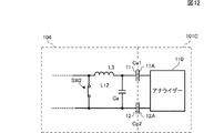
なお、本実施形態では、送電装置102の直列共振回路は、昇圧トランスT1の2次コイルL12の漏れインダクタンスLleakにより形成されているが、インダクタの実部品を設けて、そのインダクタとキャパシタCaとで形成されていてもよい。図12は、直列共振回路に昇圧トランスを用いない場合の送電装置の周波数特性を測定する方法を説明するための図である。
In the present embodiment, the series resonant circuit of the
この例では、送電装置104は、キャパシタCaと直列共振回路を形成するインダクタL3を設け、インダクタL3の一端と、基準電位とを接続するスイッチSW2を備えている。直列共振回路の周波数特性を測定する場合には、スイッチSW2をオンにする。そして、送電装置104に対し、送電側測定用治具101Cを設置して、周波数特性を測定する。
In this example, the
次に、治具側にアナライザーを接続して行う受電装置の周波数特性の測定方法について説明する。 Next, a method for measuring the frequency characteristics of the power receiving apparatus performed by connecting an analyzer to the jig side will be described.
図13A及び図13Bは、受電装置の周波数特性を測定する方法を説明するための図である。図13Aは、直列共振回路の周波数特性を測定する方法説明するための図であり、図13Bは、並列共振回路の周波数特性を測定する方法説明するための図である。 13A and 13B are diagrams for describing a method of measuring frequency characteristics of a power receiving device. FIG. 13A is a diagram for explaining a method for measuring the frequency characteristics of a series resonant circuit, and FIG. 13B is a diagram for explaining a method for measuring the frequency characteristics of a parallel resonant circuit.
図13Aに示す受電装置202は、実施形態1に係る受電装置201と同じ構成に加え、降圧トランスT2の2次コイルL22の両端を接続するスイッチSW3を備えた構成である。実施形態1で説明したように、受電装置201側では、キャパシタCbは、降圧トランスT2の1次コイルL21の直列に挿入したインダクタンスLs2(又は漏れインダクタンスLleak2)と直列共振回路を形成している。この直列共振回路の周波数特性を測定する場合には、スイッチSW3をオンにして、2次コイルL22の両端を短絡する。そして、受電装置202に対し、受電側測定用治具201Bを設置して、周波数特性を測定する。
A
図13Bに示す受電装置203は、実施形態1に係る受電装置201と同じ構成である。実施形態2で説明したように、受電装置203側では、キャパシタCbと、降圧トランスT2の1次コイルL21とにより並列共振回路が形成されている。この並列共振回路の周波数特性を測定する場合には、降圧トランスT2の2次コイルL22側を開放する必要がある。ここで、本実施形態では、ダイオードブリッジDB等の整流回路を接続したままの状態であっても測定が可能である。測定時にダイオードブリッジDBを構成するダイオードに入力される電圧がダイオードのしきい値電圧よりも小さければダイオードは高インピーダンスとなるため、負荷回路RL側が高インピーダンスとなり、整流回路のダイオード等の素子には電流がほとんど流れず、整流回路側は開放した状態とほぼ同視できる。そして、受電装置203に対し、受電側測定用治具201Bを設置して、周波数特性を測定する。
A
図14は、図13Bに示す受電装置203の周波数特性の測定結果を示す図である。図14に示すように、並列共振回路の共振周波数f2は、約519kHzである。また、周波数特性のピーク値(共振周波数f2)の1/√2倍(約−3dB)となる点の帯域幅Δf2は、約7.698kHzである。この場合、この直列共振回路のQ値は、f2/Δf2より求められ、その値は約67である。
FIG. 14 is a diagram illustrating a measurement result of frequency characteristics of the
この測定結果から、共振周波数f2が設計目標値との誤差が±5%程度となるよう、また、測定したQ値が20以上となるように、送電装置102の直列共振回路の回路設計を行う。
From this measurement result, the circuit design of the series resonance circuit of the
なお、周波数特性を測定する際、対向するアクティブ電極、及びパッシブ電極をグランド電極で挟むようにしてもよい。 When measuring the frequency characteristics, the active electrode and the passive electrode facing each other may be sandwiched between the ground electrodes.
図15、及び図16は、グランド電極を用いて周波数特性を測定する方法について説明するための図である。 15 and 16 are diagrams for explaining a method of measuring frequency characteristics using a ground electrode.
図15に示す送電装置102は、アクティブ電極11、及びパッシブ電極12に対向するように設けられたグランド電極15を備えている。また、送電側測定用治具101Cは、測定用アクティブ電極11A、及び測定用パッシブ電極12Aに対向するように設けられたグランド電極25を備えている。グランド電極15,25は、送電装置102のグランドに接続されている。
A
また、受電装置204は、アクティブ電極21、及びパッシブ電極22に対向するように設けられたグランド電極26を備えている。受電側測定用治具201Bは、測定用アクティブ電極21A、及び測定用パッシブ電極22Aに対向するように設けられたグランド電極16を備えている。グランド電極16,26は、受電装置204のグランドに接続されている。
The
図16に示す受電装置204では、キャパシタCbと、降圧トランスT2の1次コイルL21の励磁インダクタンスとにより並列共振回路が形成されている。この並列共振回路の周波数特性を測定する場合には、図13Bで説明したように、ダイオードブリッジDB等を接続したままの状態であっても、ダイオードブリッジDB側が開放した状態とほぼ同視できる。そして、受電装置204に対し、受電側測定用治具201Bを設置して、周波数特性を測定する。
In the
実際の使用状態では、高電圧部からの不要輻射を遮断する目的で、高電圧部は、電極で囲われている。このため、グランド電極15,25(グランド電極16,26)を設けて、周波数特性を測定することで、実際の使用状態により近い状態での測定結果を得ることができる。
In an actual use state, the high voltage portion is surrounded by electrodes for the purpose of blocking unnecessary radiation from the high voltage portion. For this reason, by providing the
11…アクティブ電極(第1の電極)
11A…測定用アクティブ電極(測定用第1の電極)
12…パッシブ電極(第2の電極)
12A…測定用パッシブ電極(測定用第2の電極)
13,15…グランド電極(送電側グランド電極)
16…グランド電極(治具グランド電極)
21…アクティブ電極(第3の電極)
21A…測定用アクティブ電極(測定用第3の電極)
22…パッシブ電極(第4の電極)
22A…測定用パッシブ電極(測定用第4の電極)
23,25…グランド電極(治具側グランド電極)
26…グランド電極(受電側グランド電極)
24…容量接続用電極
101,102,103,104…送電装置
101A,101B,101C…送電側測定用治具
110…アナライザー
201,202,203,204…受電装置
201A、201B…受電側測定用治具
210…アナライザー
300…ワイヤレス電力伝送システム
Ca,Cb,Ca1,Cp1,Ca2,Cp2…キャパシタ
Cc…容量
Cin…入力コンデンサ
Cout…平滑キャパシタ
DB…ダイオードブリッジ
L11…1次コイル
L12…2次コイル
L21…1次コイル
L22…2次コイル
M11,M12…測定箇所
M21,M22…測定箇所
Q1,Q2,Q3,Q4…スイッチング素子
RL…負荷回路
T1…昇圧トランス
T2…降圧トランス
Vin…直流電圧源11 ... Active electrode (first electrode)
11A: Active electrode for measurement (first electrode for measurement)
12: Passive electrode (second electrode)
12A: Passive electrode for measurement (second electrode for measurement)
13, 15 ... Ground electrode (ground electrode on the power transmission side)
16 ... Ground electrode (Jig ground electrode)
21 ... Active electrode (third electrode)
21A ... Active electrode for measurement (third electrode for measurement)
22: Passive electrode (fourth electrode)
22A: Passive electrode for measurement (fourth electrode for measurement)
23, 25 ... Ground electrode (jig side ground electrode)
26: Ground electrode (power-receiving-side ground electrode)
24 ... Electrodes for
Claims (24)
前記第1の電極と間隙を置いて対向する第3の電極、及び、前記第2の電極と接触する、または、間隙を置いて対向する第4の電極と、前記第3の電極、及び前記第4の電極に接続される受電共振回路とを有する受電装置と、
を備え、前記送電装置から受電装置へ電界結合により電力伝送するワイヤレス電力伝送システムにおける前記送電装置の周波数特性を測定する周波数特性測定方法において、
前記第1の電極と間隙を置いて対向する測定用第1の電極、及び、前記第2の電極と接触する、または、間隙を置いて対向する測定用第2の電極を有し、前記測定用第1の電極、及び前記測定用第2の電極を接続した送電側測定用治具を、前記送電装置に対し設置して、前記高周波発生回路と前記送電共振回路との間で、前記送電共振回路の周波数特性を測定する、
周波数特性測定方法。A power transmission device comprising: a high frequency generation circuit; a power transmission resonance circuit connected to the high frequency generation circuit; and a first electrode and a second electrode connected to an output side of the power transmission resonance circuit;
A third electrode that faces the first electrode with a gap therebetween, and a fourth electrode that makes contact with the second electrode or faces the gap with a gap, the third electrode, and the third electrode, A power receiving device having a power receiving resonance circuit connected to the fourth electrode;
In a frequency characteristic measurement method for measuring the frequency characteristic of the power transmission device in a wireless power transmission system that transmits power by electric field coupling from the power transmission device to the power reception device,
A first electrode for measurement opposed to the first electrode with a gap, and a second electrode for measurement which is in contact with the second electrode or opposed to the second electrode with a gap; A power transmission side measuring jig connected to the first electrode for measurement and the second electrode for measurement is installed in the power transmission device, and the power transmission between the high frequency generation circuit and the power transmission resonance circuit. Measure the frequency characteristics of the resonant circuit,
Frequency characteristic measurement method.
請求項1に記載の周波数特性測定方法。The frequency characteristic is a resonance frequency and a Q value of the power transmission resonance circuit.
The frequency characteristic measuring method according to claim 1.
請求項1又は2に記載の周波数特性測定方法。In a state where the first electrode for measurement and the second electrode for measurement are short-circuited, frequency characteristics are measured,
The frequency characteristic measuring method according to claim 1 or 2.
請求項1又は2に記載の周波数特性測定方法。Measuring frequency characteristics in a state where the first electrode for measurement and the second electrode for measurement are connected via a capacitor;
The frequency characteristic measuring method according to claim 1 or 2.
請求項1から4の何れかに記載の周波数特性測定方法。A power transmission side ground electrode provided in the power transmission device and connected to a ground potential of the power transmission device; a jig side ground electrode provided in the power transmission side measurement jig and connected to the ground potential of the power transmission device; Then, the frequency characteristics are measured in a state where the first electrode, the second electrode, the first electrode for measurement, and the second electrode for measurement are sandwiched,
The frequency characteristic measuring method according to claim 1.
前記第1の電極と間隙を置いて対向する第3の電極、及び、前記第2の電極と接触する、または、間隙を置いて対向する第4の電極と、前記第3の電極、及び前記第4の電極が入力側に接続された受電共振回路と、前記受電共振回路の出力側に接続された整流回路とを有する受電装置と、
を備え、前記送電装置から受電装置へ電界結合により電力伝送するワイヤレス電力伝送システムにおける前記受電装置の周波数特性を測定する周波数特性測定方法において、
前記第3の電極と間隙を置いて対向する測定用第3の電極、及び、前記第4の電極と接触する、または、間隙を置いて対向する測定用第4の電極を有し、前記測定用第3の電極、及び前記測定用第4の電極を接続した受電側測定用治具を、前記受電装置に対し設置して、前記受電共振回路と前記整流回路との間で、前記受電共振回路の周波数特性を測定する、
周波数特性測定方法。A power transmission device comprising: a high frequency generation circuit; a power transmission resonance circuit connected to the high frequency generation circuit; and a first electrode and a second electrode connected to an output side of the power transmission resonance circuit;
A third electrode that faces the first electrode with a gap therebetween, and a fourth electrode that makes contact with the second electrode or faces the gap with a gap, the third electrode, and the third electrode, A power receiving device having a power receiving resonance circuit having a fourth electrode connected to an input side; and a rectifier circuit connected to an output side of the power receiving resonance circuit;
In a frequency characteristic measurement method for measuring a frequency characteristic of the power receiving device in a wireless power transmission system that transmits power by electric field coupling from the power transmitting device to the power receiving device.
A third electrode for measurement opposed to the third electrode with a gap, and a fourth electrode for measurement which is in contact with the fourth electrode or opposed to the fourth electrode with a gap; A power receiving-side measuring jig connected to the third electrode for measurement and the fourth electrode for measurement is installed on the power receiving device, and the power receiving resonance is generated between the power receiving resonance circuit and the rectifier circuit. Measure the frequency characteristics of the circuit,
Frequency characteristic measurement method.
請求項6に記載の周波数特性測定方法。The frequency characteristic is a resonance frequency and a Q value of the power receiving resonance circuit.
The frequency characteristic measuring method according to claim 6.
請求項6又は7に記載の周波数特性測定方法。In a state where the third electrode for measurement and the fourth electrode for measurement are short-circuited, frequency characteristics are measured,
The frequency characteristic measuring method according to claim 6 or 7.
請求項6又は7に記載の周波数特性測定方法。Measuring frequency characteristics in a state where the third electrode for measurement and the fourth electrode for measurement are connected via a capacitor;
The frequency characteristic measuring method according to claim 6 or 7.
請求項6から9の何れかに記載の周波数特性測定方法。A power receiving side ground electrode provided in the power receiving device and connected to a ground potential of the power receiving device; a jig side ground electrode provided in the power receiving side measurement jig and connected to the ground potential of the power receiving device; Then, the frequency characteristics are measured in a state where the third electrode, the fourth electrode, the third electrode for measurement, and the fourth electrode for measurement are sandwiched,
The frequency characteristic measuring method according to claim 6.
前記第1の電極と間隙を置いて対向する第3の電極、及び、前記第2の電極と接触する、または、間隙を置いて対向する第4の電極と、前記第3の電極、及び前記第4の電極に接続される受電共振回路とを有する受電装置と、
を備え、前記送電装置から受電装置へ電界結合により電力伝送するワイヤレス電力伝送システムにおける前記送電装置の周波数特性を測定する周波数特性測定方法において、
前記第1の電極と間隙を置いて対向する測定用第1の電極、及び、前記第2の電極と接触する、または、間隙を置いて対向する測定用第2の電極を有する送電側測定用治具を、前記送電装置に対し設置して、前記直列共振回路の前記第1の入力端、及び前記第2の入力端を接続した状態で、前記測定用第1の電極、及び、前記測定用第2の電極の間で、前記直列共振回路の周波数を測定する、
周波数特性測定方法。A high frequency generation circuit, a series resonance circuit having a first input terminal and a second input terminal connected to the high frequency generation circuit, a first electrode connected to the output side of the series resonance circuit, and a second electrode A power transmission device having an electrode;
A third electrode that faces the first electrode with a gap therebetween, and a fourth electrode that makes contact with the second electrode or faces the gap with a gap, the third electrode, and the third electrode, A power receiving device having a power receiving resonance circuit connected to the fourth electrode;
In a frequency characteristic measurement method for measuring the frequency characteristic of the power transmission device in a wireless power transmission system that transmits power by electric field coupling from the power transmission device to the power reception device,
The first electrode for measurement facing the first electrode with a gap and the second electrode for measurement having the second electrode for measurement facing the second electrode or facing the second electrode A jig is installed on the power transmission device, and the first input terminal and the second input terminal of the series resonant circuit are connected, and the first electrode for measurement and the measurement Measuring the frequency of the series resonant circuit between the second electrodes for use;
Frequency characteristic measurement method.
請求項11に記載の周波数特性測定方法。The frequency characteristics are a resonance frequency and a Q value of the series resonance circuit.
The frequency characteristic measuring method according to claim 11.
請求項11又は12に記載の周波数特性測定方法。In a state where the first input terminal and the second input terminal of the series resonant circuit are short-circuited, a frequency characteristic is measured.
The frequency characteristic measuring method according to claim 11 or 12.
請求項11又は12に記載の周波数特性測定方法。In the state where the first input end of the series resonant circuit and the second input end are connected via a capacitor, a frequency characteristic is measured.
The frequency characteristic measuring method according to claim 11 or 12.
前記第1の電極と間隙を置いて対向する第3の電極、及び、前記第2の電極と接触する、または、間隙を置いて対向する第4の電極と、前記第3の電極、及び前記第4の電極に接続される受電共振回路とを有する受電装置と、
を備え、前記送電装置から受電装置へ電界結合により電力伝送するワイヤレス電力伝送システムにおける前記送電装置の周波数特性を測定する周波数特性測定方法において、
前記第1の電極と間隙を置いて対向する測定用第1の電極、及び、前記第2の電極と接触する、または、間隙を置いて対向する測定用第2の電極を有する送電側測定用治具を、前記送電装置に対し設置して、前記測定用第1の電極、及び、前記測定用第2の電極の間で、前記並列共振回路の周波数を測定する、
周波数特性測定方法。A high frequency generation circuit; a parallel resonance circuit having a first input terminal and a second input terminal connected to the high frequency generation circuit; a first electrode connected to the output side of the parallel resonance circuit; A power transmission device having an electrode;
A third electrode that faces the first electrode with a gap therebetween, and a fourth electrode that makes contact with the second electrode or faces the gap with a gap, the third electrode, and the third electrode, A power receiving device having a power receiving resonance circuit connected to the fourth electrode;
In a frequency characteristic measurement method for measuring the frequency characteristic of the power transmission device in a wireless power transmission system that transmits power by electric field coupling from the power transmission device to the power reception device,
The first electrode for measurement facing the first electrode with a gap and the second electrode for measurement having the second electrode for measurement facing the second electrode or facing the second electrode A jig is installed for the power transmission device, and the frequency of the parallel resonant circuit is measured between the first electrode for measurement and the second electrode for measurement.
Frequency characteristic measurement method.
請求項15に記載の周波数特性測定方法。The frequency characteristic is a resonance frequency and a Q value of the parallel resonance circuit.
The frequency characteristic measuring method according to claim 15.
請求項11から16の何れかに記載の周波数特性測定方法。A power transmission side ground electrode provided in the power transmission device and connected to a ground potential of the power transmission device; a jig side ground electrode provided in the power transmission side measurement jig and connected to the ground potential of the power transmission device; Then, the frequency characteristics are measured in a state where the first electrode, the second electrode, the first electrode for measurement, and the second electrode for measurement are sandwiched,
The frequency characteristic measuring method according to claim 11.
前記第1の電極と間隙を置いて対向する第3の電極、及び、前記第2の電極と接触する、または、間隙を置いて対向する第4の電極と、前記第3の電極、及び前記第4の電極に接続される直列共振回路と、前記直列共振回路の第1の出力端、及び第2の出力端に接続された整流回路とを有する受電装置と、
を備え、前記送電装置から受電装置へ電界結合により電力伝送するワイヤレス電力伝送システムにおける前記受電装置の周波数特性を測定する周波数特性測定方法において、
前記第3の電極と間隙を置いて対向する測定用第3の電極、及び、前記第4の電極と接触する、または、間隙を置いて対向する測定用第4の電極を有する受電側測定用治具を、前記受電装置に対し設置して、前記直列共振回路の前記第1の出力端、及び前記第2の出力端を接続した状態で、前記測定用第3の電極、及び、前記測定用第4の電極の間で、前記直列共振回路の周波数を測定する、
周波数特性測定方法。A power transmission device comprising: a high frequency generation circuit; a power transmission resonance circuit connected to the high frequency generation circuit; and a first electrode and a second electrode connected to an output side of the power transmission resonance circuit;
A third electrode that faces the first electrode with a gap therebetween, and a fourth electrode that makes contact with the second electrode or faces the gap with a gap, the third electrode, and the third electrode, A power receiving device having a series resonant circuit connected to a fourth electrode; a first output terminal of the series resonant circuit; and a rectifier circuit connected to a second output terminal;
In a frequency characteristic measurement method for measuring a frequency characteristic of the power receiving device in a wireless power transmission system that transmits power by electric field coupling from the power transmitting device to the power receiving device.
The third electrode for measurement facing the third electrode with a gap, and the fourth electrode for measurement having the fourth electrode for measurement facing the fourth electrode or facing the gap with the gap A jig is installed on the power receiving device, and the first output end and the second output end of the series resonant circuit are connected, and the measurement third electrode and the measurement Measuring the frequency of the series resonant circuit between the fourth electrodes for use;
Frequency characteristic measurement method.
請求項18に記載の周波数特性測定方法。The frequency characteristics are a resonance frequency and a Q value of the series resonance circuit.
The frequency characteristic measuring method according to claim 18.
請求項18又は19に記載の周波数特性測定方法。In a state where the first output terminal and the second output terminal of the series resonant circuit are short-circuited, frequency characteristics are measured.
The frequency characteristic measuring method according to claim 18 or 19.
請求項18又は19に記載の周波数特性測定方法。In the state where the first output terminal and the second output terminal of the series resonant circuit are connected via a capacitor, a frequency characteristic is measured.
The frequency characteristic measuring method according to claim 18 or 19.
前記第1の電極と間隙を置いて対向する第3の電極、及び、前記第2の電極と接触する、または、間隙を置いて対向する第4の電極と、前記第3の電極、及び前記第4の電極に接続される並列共振回路と、前記並列共振回路の第1の出力端、及び第2の出力端に接続された整流回路とを有する受電装置と、
を備え、前記送電装置から受電装置へ電界結合により電力伝送するワイヤレス電力伝送システムにおける前記受電装置の周波数特性を測定する周波数特性測定方法において、
前記第3の電極と間隙を置いて対向する測定用第3の電極、及び、前記第4の電極と接触する、または、間隙を置いて対向する測定用第4の電極を有する受電側測定用治具を、前記受電装置に対し設置して、前記測定用第3の電極、及び、前記測定用第4の電極の間で、前記並列共振回路の周波数を測定する、
周波数特性測定方法。A power transmission device comprising: a high frequency generation circuit; a power transmission resonance circuit connected to the high frequency generation circuit; and a first electrode and a second electrode connected to an output side of the power transmission resonance circuit;
A third electrode that faces the first electrode with a gap therebetween, and a fourth electrode that makes contact with the second electrode or faces the gap with a gap, the third electrode, and the third electrode, A power receiving device having a parallel resonant circuit connected to a fourth electrode, a first output terminal of the parallel resonant circuit, and a rectifier circuit connected to a second output terminal;
In a frequency characteristic measurement method for measuring a frequency characteristic of the power receiving device in a wireless power transmission system that transmits power by electric field coupling from the power transmitting device to the power receiving device.
The third electrode for measurement facing the third electrode with a gap, and the fourth electrode for measurement having the fourth electrode for measurement facing the fourth electrode or facing the gap with the gap A jig is installed on the power receiving device, and the frequency of the parallel resonant circuit is measured between the third electrode for measurement and the fourth electrode for measurement.
Frequency characteristic measurement method.
請求項22に記載の周波数特性測定方法。The frequency characteristic is a resonance frequency and a Q value of the parallel resonance circuit.
The frequency characteristic measuring method according to claim 22.
請求項18から23の何れかに記載の周波数特性測定方法。A power receiving side ground electrode provided in the power receiving device and connected to a ground potential of the power receiving device; a jig side ground electrode provided in the power receiving side measurement jig and connected to the ground potential of the power receiving device; Then, the frequency characteristics are measured in a state where the third electrode, the fourth electrode, the third electrode for measurement, and the fourth electrode for measurement are sandwiched,
The frequency characteristic measuring method according to any one of claims 18 to 23.
Applications Claiming Priority (5)
| Application Number | Priority Date | Filing Date | Title |
|---|---|---|---|
| JP2013234867 | 2013-11-13 | ||
| JP2013234867 | 2013-11-13 | ||
| JP2014036938 | 2014-02-27 | ||
| JP2014036938 | 2014-02-27 | ||
| PCT/JP2014/079291 WO2015072374A1 (en) | 2013-11-13 | 2014-11-05 | Frequency characteristic measuring method |
Publications (2)
| Publication Number | Publication Date |
|---|---|
| JPWO2015072374A1 JPWO2015072374A1 (en) | 2017-03-16 |
| JP6112222B2 true JP6112222B2 (en) | 2017-04-12 |
Family
ID=53057310
Family Applications (1)
| Application Number | Title | Priority Date | Filing Date |
|---|---|---|---|
| JP2015547738A Active JP6112222B2 (en) | 2013-11-13 | 2014-11-05 | Frequency characteristic measurement method |
Country Status (3)
| Country | Link |
|---|---|
| US (1) | US10018659B2 (en) |
| JP (1) | JP6112222B2 (en) |
| WO (1) | WO2015072374A1 (en) |
Families Citing this family (2)
| Publication number | Priority date | Publication date | Assignee | Title |
|---|---|---|---|---|
| CN209488195U (en) * | 2016-10-12 | 2019-10-11 | Oppo广东移动通信有限公司 | mobile terminal |
| CN108124498B (en) * | 2017-02-24 | 2020-07-24 | Oppo广东移动通信有限公司 | Equalizing circuit, device to be charged and charging control method |
Family Cites Families (5)
| Publication number | Priority date | Publication date | Assignee | Title |
|---|---|---|---|---|
| JP4557049B2 (en) * | 2008-06-09 | 2010-10-06 | ソニー株式会社 | Transmission system, power supply apparatus, power reception apparatus, and transmission method |
| CN102239633B (en) * | 2008-09-27 | 2017-01-18 | 韦特里西提公司 | Wireless energy transfer systems |
| GB2509030B (en) | 2011-10-12 | 2016-06-22 | Murata Manufacturing Co | Wireless power transmission system |
| JP5843066B2 (en) * | 2012-03-06 | 2016-01-13 | 株式会社村田製作所 | Power transmission system and power transmission device |
| WO2013132702A1 (en) * | 2012-03-07 | 2013-09-12 | 株式会社 村田製作所 | System for transmitting electric power and power-transmission device |
-
2014
- 2014-11-05 JP JP2015547738A patent/JP6112222B2/en active Active
- 2014-11-05 WO PCT/JP2014/079291 patent/WO2015072374A1/en active Application Filing
-
2016
- 2016-04-21 US US15/134,844 patent/US10018659B2/en active Active
Also Published As
| Publication number | Publication date |
|---|---|
| JPWO2015072374A1 (en) | 2017-03-16 |
| WO2015072374A1 (en) | 2015-05-21 |
| US20160252553A1 (en) | 2016-09-01 |
| US10018659B2 (en) | 2018-07-10 |
Similar Documents
| Publication | Publication Date | Title |
|---|---|---|
| Esteban et al. | A comparative study of power supply architectures in wireless EV charging systems | |
| KR101438910B1 (en) | The Wired-Wireless Combined Power Transmission Apparatus and The Method using the same | |
| JP2015008625A5 (en) | ||
| EP3306781A1 (en) | Wireless power transmission system and method for driving same | |
| KR101604172B1 (en) | Capacitively coupled Wireless Charging Apparatus | |
| JP2015008625A (en) | Transmitter for wireless power transmission | |
| JP6037022B2 (en) | Power transmission device, wireless power transmission system, and power transmission discrimination method | |
| JP5862844B2 (en) | Wireless power transmission system | |
| JP5716877B2 (en) | Power transmission system | |
| JP5516824B2 (en) | Power transmission system | |
| US20130334893A1 (en) | Power transmission system and power transmitting apparatus | |
| US20170366047A1 (en) | Wireless power transmission apparatus for performing non-contact transmission by electromagnetic induction | |
| WO2016136567A1 (en) | Voltage detection circuit, power transmission device, and power transmission system | |
| JP5741778B2 (en) | Parameter derivation method | |
| JP2017070055A (en) | Wireless power transmission system and power transmission device | |
| JP6112222B2 (en) | Frequency characteristic measurement method | |
| JP6183243B2 (en) | Power transmission system, power receiving device, and power transmitting device | |
| CN110401265B (en) | Power transmitting device, wireless charging system and demodulation method thereof | |
| JP6536588B2 (en) | Power transmission device and power transmission system | |
| JP2015050848A (en) | Power transmission device and wireless power transmission system | |
| Vadde et al. | Enhancement of efficiency for wireless power transfer system using wireless link | |
| KR101393852B1 (en) | Apparatus for supplying power and apparatus for transmitting wireless power and method for supplying power | |
| KR20230045247A (en) | Wireless power transmitter comprising an impedance matching circuit and method for transmitting a wireless power | |
| WO2015111601A1 (en) | Power transmission device, and power transmission system |
Legal Events
| Date | Code | Title | Description |
|---|---|---|---|
| TRDD | Decision of grant or rejection written | ||
| A01 | Written decision to grant a patent or to grant a registration (utility model) |
Free format text: JAPANESE INTERMEDIATE CODE: A01 Effective date: 20170214 |
|
| A61 | First payment of annual fees (during grant procedure) |
Free format text: JAPANESE INTERMEDIATE CODE: A61 Effective date: 20170227 |
|
| R150 | Certificate of patent or registration of utility model |
Ref document number: 6112222 Country of ref document: JP Free format text: JAPANESE INTERMEDIATE CODE: R150 |