JP6103917B2 - Electrical connector assembly - Google Patents
Electrical connector assembly Download PDFInfo
- Publication number
- JP6103917B2 JP6103917B2 JP2012275677A JP2012275677A JP6103917B2 JP 6103917 B2 JP6103917 B2 JP 6103917B2 JP 2012275677 A JP2012275677 A JP 2012275677A JP 2012275677 A JP2012275677 A JP 2012275677A JP 6103917 B2 JP6103917 B2 JP 6103917B2
- Authority
- JP
- Japan
- Prior art keywords
- contact portion
- connector
- terminal
- contact
- conductive
- Prior art date
- Legal status (The legal status is an assumption and is not a legal conclusion. Google has not performed a legal analysis and makes no representation as to the accuracy of the status listed.)
- Active
Links
- 230000002093 peripheral effect Effects 0.000 claims description 13
- 239000002184 metal Substances 0.000 claims description 12
- 239000011810 insulating material Substances 0.000 claims description 3
- 230000013011 mating Effects 0.000 description 22
- 238000006073 displacement reaction Methods 0.000 description 15
- 238000007667 floating Methods 0.000 description 11
- 230000004308 accommodation Effects 0.000 description 7
- 230000005489 elastic deformation Effects 0.000 description 6
- 238000005452 bending Methods 0.000 description 5
- 230000008878 coupling Effects 0.000 description 4
- 238000010168 coupling process Methods 0.000 description 4
- 238000005859 coupling reaction Methods 0.000 description 4
- 239000004020 conductor Substances 0.000 description 3
- 239000012777 electrically insulating material Substances 0.000 description 2
- 230000036544 posture Effects 0.000 description 2
- 238000003466 welding Methods 0.000 description 2
- 230000008859 change Effects 0.000 description 1
- 238000006243 chemical reaction Methods 0.000 description 1
- 238000004891 communication Methods 0.000 description 1
- 239000000470 constituent Substances 0.000 description 1
- 230000007423 decrease Effects 0.000 description 1
- 238000010586 diagram Methods 0.000 description 1
- 230000000694 effects Effects 0.000 description 1
- 230000006872 improvement Effects 0.000 description 1
- 238000003780 insertion Methods 0.000 description 1
- 230000037431 insertion Effects 0.000 description 1
- 238000005304 joining Methods 0.000 description 1
- 238000000465 moulding Methods 0.000 description 1
- 239000012811 non-conductive material Substances 0.000 description 1
- 238000005192 partition Methods 0.000 description 1
- 230000000149 penetrating effect Effects 0.000 description 1
- 238000011946 reduction process Methods 0.000 description 1
- 230000001105 regulatory effect Effects 0.000 description 1
- 238000005096 rolling process Methods 0.000 description 1
- 229910000679 solder Inorganic materials 0.000 description 1
- 238000003860 storage Methods 0.000 description 1
Images


Classifications
-
- H—ELECTRICITY
- H01—ELECTRIC ELEMENTS
- H01R—ELECTRICALLY-CONDUCTIVE CONNECTIONS; STRUCTURAL ASSOCIATIONS OF A PLURALITY OF MUTUALLY-INSULATED ELECTRICAL CONNECTING ELEMENTS; COUPLING DEVICES; CURRENT COLLECTORS
- H01R12/00—Structural associations of a plurality of mutually-insulated electrical connecting elements, specially adapted for printed circuits, e.g. printed circuit boards [PCB], flat or ribbon cables, or like generally planar structures, e.g. terminal strips, terminal blocks; Coupling devices specially adapted for printed circuits, flat or ribbon cables, or like generally planar structures; Terminals specially adapted for contact with, or insertion into, printed circuits, flat or ribbon cables, or like generally planar structures
- H01R12/70—Coupling devices
- H01R12/7082—Coupling device supported only by cooperation with PCB
-
- H—ELECTRICITY
- H01—ELECTRIC ELEMENTS
- H01R—ELECTRICALLY-CONDUCTIVE CONNECTIONS; STRUCTURAL ASSOCIATIONS OF A PLURALITY OF MUTUALLY-INSULATED ELECTRICAL CONNECTING ELEMENTS; COUPLING DEVICES; CURRENT COLLECTORS
- H01R13/00—Details of coupling devices of the kinds covered by groups H01R12/70 or H01R24/00 - H01R33/00
- H01R13/40—Securing contact members in or to a base or case; Insulating of contact members
- H01R13/42—Securing in a demountable manner
- H01R13/424—Securing in base or case composed of a plurality of insulating parts having at least one resilient insulating part
-
- H—ELECTRICITY
- H01—ELECTRIC ELEMENTS
- H01R—ELECTRICALLY-CONDUCTIVE CONNECTIONS; STRUCTURAL ASSOCIATIONS OF A PLURALITY OF MUTUALLY-INSULATED ELECTRICAL CONNECTING ELEMENTS; COUPLING DEVICES; CURRENT COLLECTORS
- H01R13/00—Details of coupling devices of the kinds covered by groups H01R12/70 or H01R24/00 - H01R33/00
- H01R13/62—Means for facilitating engagement or disengagement of coupling parts or for holding them in engagement
- H01R13/625—Casing or ring with bayonet engagement
-
- H—ELECTRICITY
- H01—ELECTRIC ELEMENTS
- H01R—ELECTRICALLY-CONDUCTIVE CONNECTIONS; STRUCTURAL ASSOCIATIONS OF A PLURALITY OF MUTUALLY-INSULATED ELECTRICAL CONNECTING ELEMENTS; COUPLING DEVICES; CURRENT COLLECTORS
- H01R13/00—Details of coupling devices of the kinds covered by groups H01R12/70 or H01R24/00 - H01R33/00
- H01R13/62—Means for facilitating engagement or disengagement of coupling parts or for holding them in engagement
- H01R13/627—Snap or like fastening
-
- H—ELECTRICITY
- H01—ELECTRIC ELEMENTS
- H01R—ELECTRICALLY-CONDUCTIVE CONNECTIONS; STRUCTURAL ASSOCIATIONS OF A PLURALITY OF MUTUALLY-INSULATED ELECTRICAL CONNECTING ELEMENTS; COUPLING DEVICES; CURRENT COLLECTORS
- H01R12/00—Structural associations of a plurality of mutually-insulated electrical connecting elements, specially adapted for printed circuits, e.g. printed circuit boards [PCB], flat or ribbon cables, or like generally planar structures, e.g. terminal strips, terminal blocks; Coupling devices specially adapted for printed circuits, flat or ribbon cables, or like generally planar structures; Terminals specially adapted for contact with, or insertion into, printed circuits, flat or ribbon cables, or like generally planar structures
- H01R12/70—Coupling devices
- H01R12/71—Coupling devices for rigid printing circuits or like structures
- H01R12/72—Coupling devices for rigid printing circuits or like structures coupling with the edge of the rigid printed circuits or like structures
- H01R12/73—Coupling devices for rigid printing circuits or like structures coupling with the edge of the rigid printed circuits or like structures connecting to other rigid printed circuits or like structures
- H01R12/735—Printed circuits including an angle between each other
- H01R12/737—Printed circuits being substantially perpendicular to each other
-
- H—ELECTRICITY
- H01—ELECTRIC ELEMENTS
- H01R—ELECTRICALLY-CONDUCTIVE CONNECTIONS; STRUCTURAL ASSOCIATIONS OF A PLURALITY OF MUTUALLY-INSULATED ELECTRICAL CONNECTING ELEMENTS; COUPLING DEVICES; CURRENT COLLECTORS
- H01R13/00—Details of coupling devices of the kinds covered by groups H01R12/70 or H01R24/00 - H01R33/00
- H01R13/02—Contact members
- H01R13/15—Pins, blades or sockets having separate spring member for producing or increasing contact pressure
- H01R13/187—Pins, blades or sockets having separate spring member for producing or increasing contact pressure with spring member in the socket
Landscapes
- Coupling Device And Connection With Printed Circuit (AREA)
- Details Of Connecting Devices For Male And Female Coupling (AREA)
Description
本発明は電気コネクタ組立体、特に、導電端子を有する電気コネクタ組立体に関する。 The present invention relates to an electrical connector assembly, and more particularly to an electrical connector assembly having conductive terminals.
この種の電気コネクタ組立体としては、例えば、特許文献1に開示されているコネクタ組立体が知られている。
As this type of electrical connector assembly, for example, a connector assembly disclosed in
この特許文献1のコネクタ組立体は、一方の回路基板に取り付けられ相手コネクタと、他方の回路基板に取り付けられた他方の相手コネクタとを接続する中間コネクタとを有している。この特許文献1のコネクタ組立体では、上記一方そして他方の回路基板が互いに平行な面をなすようにして、上記中間コネクタが両相手コネクタを接続する。したがって、これらの両コネクタそして中間コネクタの互いの対応端子は一直線上に位置している。すなわち、中間コネクタと一方の相手コネクタとの嵌合方向が、中間コネクタと他方の相手コネクタとの嵌合方向に一致している。
The connector assembly of this
両方の相手コネクタは、嵌合方向に延びるピン状(直状)の固定コンタクト(端子)がコネクタの嵌合方向に対して直角な面で行そして列をなす複数位置に植設されている。これに対し、中間コネクタは、金属帯をその板厚方向に屈曲成形して該板厚方向に弾性変形可能な可動コンタクトが設けられている。一つの可動コンタクトは、一つの固定コンタクトを挟圧保持するように板厚方向に対向するようにして対をなして設けられた二つのばね片を、上記嵌合方向での中間位置で、連結部により連結して一体化して両ばね片の間隔を一定に保っている。この可動コンタクトの一対のばね片は上記連結部を基部とする片持ち梁状をなし、それぞれの相手コンタクト側となる両方の自由端側に、局部的に間隔を狭めた接触部を形成し、上記嵌合方向に直角方向で対向して喉状をなす一対の接触部で、弾性撓み変形して、相手コネクタの固定コンタクトを受け入れ挟圧するようになっている。 In both the mating connectors, pin-like (straight) fixed contacts (terminals) extending in the fitting direction are implanted in a plurality of positions in rows and columns on a plane perpendicular to the fitting direction of the connector. On the other hand, the intermediate connector is provided with a movable contact that can be elastically deformed in the thickness direction by bending a metal strip in the thickness direction. One movable contact connects two spring pieces, which are provided in pairs so as to face each other in the thickness direction so as to hold and hold one fixed contact, at an intermediate position in the fitting direction. The two spring pieces are kept constant by being connected and integrated with each other. A pair of spring pieces of this movable contact has a cantilever shape with the above-mentioned connecting portion as a base, and forms a contact portion with a locally narrowed distance on both free ends that are the counterpart contact sides, The pair of contact portions that form a throat opposite to the fitting direction at right angles are elastically deformed to receive and clamp the fixed contact of the mating connector.
このような特許文献1のコネクタ組立体では、両相手コネクタと中間コネクタとが接続されている状態で、両相手コネクタは、上記嵌合方向に対して直角な面内での異なる二方向で、中間コネクタに対して、許容範囲内でそれぞれ相対移動可能である。
In such a connector assembly of
この二方向の移動は、第一には、中間コネクタの可動コンタクトのばね片の板厚方向であり、固定コンタクトに圧せられた際の可動コンタクトの板厚方向での弾性変形により可能となり、第二にはばね片の板面方向であり、固定コンタクトが可動コンタクトのばね片の板面に沿って摺動することで可能となる。 This two-way movement is primarily in the plate thickness direction of the spring piece of the movable contact of the intermediate connector, and is enabled by elastic deformation in the plate thickness direction of the movable contact when pressed against the fixed contact, The second is the direction of the plate surface of the spring piece, which can be achieved by sliding the fixed contact along the plate surface of the spring piece of the movable contact.
かくして、特許文献1のコネクタ組立体は、二つの相手コネクタ同士は、嵌合方向に対して直角な面内での二方向で相手コネクタ同士の位置のずれによる影響を吸収する、いわゆるフローティングが上記二方向で可能となる。
Thus, in the connector assembly of
しかしながら、特許文献1の中間コネクタにあっては、可動コンタクトが金属帯をその板厚方向に屈曲して形成されていること、板厚方向で対向する一対のばね片が連結部で連結されていること、また、上下のばね片が一部材としてつながっていることに起因して、いくつかの点で改善の余地を残している。さらには、特許文献1の中間コネクタは、両方の相手コネクタとの嵌合方向が一直線となるような接続しかできず、二つの相手コネクタがそれぞれ取り付けられる回路基板同士が直角な位置関係の接続には不向きである。
However, in the intermediate connector of
特許文献1にあっては、第一には、中間コネクタの端子の接触部が板厚方向にのみ屈曲されて形成されている結果、上述の二方向でのフローティングのうち一方は板厚方向での弾性変形、そして他方が板厚面方向での摩擦力を伴う摺動として得られるものであり、この二つの方向でのフローティングによる移動のモード、すなわち、固定コンタクトと可動コンタクトとの間で作用する力が上記二つの方向の一方では弾性力そして他方では摩擦力であって異質であるということである。その結果、上記フローティングによる移動の際、両コネクタが上記嵌合方向に対して直角な面内で一つの直線の方向にずれた場合、そのずれの方向が異なる場合、すなわち、上記嵌合方向に対して直角な面内であっても上記一つの直線に対して角度をもっている方向にずれた場合、変位量や接触圧が異なることにより、ずれによる影響の吸収能力に差が出るという事態が生ずる。換言すれば、例えば、弾性変形する方向のずれではその変形量に比例した接圧となり、変形量によって接圧は大きくもなり小さくもなるが、摺動方向のずれでは、摺動による移動量に係らず、移動した位置での接触部がもともと受けている初期弾性力であって一定した接圧であるということになる。
In
第二には、ばね片は板厚方向にしか屈曲されていないので、固定コンタクトに対する喉状の接触部位が直線であり、その接触線の長さは、四角形断面をなしている固定コンタクトの該四角形の一辺の長が最大となり、接触線の長さは十分とは言えず、接触面積はきわめて小さい。ましてや、固定コンタクトが円形断面ならば、接触部位は点となってしまう。 Secondly, since the spring piece is bent only in the plate thickness direction, the throat-like contact portion with respect to the fixed contact is a straight line, and the length of the contact line is that of the fixed contact having a square cross section. The length of one side of the quadrangle is maximized, the length of the contact line is not sufficient, and the contact area is extremely small. In addition, if the fixed contact has a circular cross section, the contact portion becomes a point.
第三には、上述のごとく、上下のばね片が一体なので、上記二方向のフローティングでのモードの差異から、二つの相手コネクタ同士が同一直線方向でなく互いに異なる方向にずれた場合にも、両相手コネクタ同士間で上記ずれによる影響の吸収能力に差を生ずる。 Third, as described above, since the upper and lower spring pieces are integrated, from the difference in the mode in the floating in the two directions, even when the two mating connectors are shifted in different directions rather than in the same linear direction, There is a difference in the ability to absorb the influence of the deviation between the mating connectors.
第四には、上下のばね片が一体なので、上下のばね片は互いに拘束し合って剛性が高くなっており、弾性変形方向では、接圧は大きいものの弾性変形量(移動量)が小さく、又、弾性変位に独立性がない。 Fourthly, since the upper and lower spring pieces are integrated, the upper and lower spring pieces are constrained to each other and have high rigidity. In the elastic deformation direction, although the contact pressure is large, the elastic deformation amount (movement amount) is small. Also, the elastic displacement is not independent.
さらに、第五には、中間コネクタが両相手コネクタに対して一直線の方向の嵌合接続しかできず、二つの相手コネクタの回路基板が直角に配置されるような、いわゆるライトアングル接続には適用できないということである。 Furthermore, the fifth is applicable to so-called right-angle connections where the intermediate connector can only be fitted and connected to both mating connectors in a straight line, and the circuit boards of the two mating connectors are arranged at right angles. That is not possible.
本発明は、このような事情に鑑み、中間コネクタの導電端子がその両端で接触接続される両相手コネクタの受入端子を、互いに独立させかつ周方向のどの角度位置でも同じモードのフローティングが行えると共に、ライトアングル接続に好適な電気コネクタ組立体を提供することを課題とする。 In view of such circumstances, the present invention allows the receiving terminals of both mating connectors to which the conductive terminals of the intermediate connector are contact-connected at both ends to be independent of each other and perform floating in the same mode at any angular position in the circumferential direction. An object of the present invention is to provide an electrical connector assembly suitable for right angle connection.
本発明に係る電気コネクタ組立体は、第一の回路部材に取り付けられる第一取付コネクタと、第二の回路部材に取り付けられ第二取付コネクタと、第一取付コネクタと第二取付コネクタの間に介在して第一取付コネクタと第二取付コネクタを接続する中間コネクタとを有し、該中間コネクタがハウジング内に複数の導電端子を備え、上記第一取付コネクタと第二取付コネクタが上記導電端子のそれぞれの対応端部に形成された軸状の接触部をそれらの軸線方向で受け入れて該接触部の周面と接触する第一受入端子と第二受入端子をそれぞれ備える。 The electrical connector assembly according to the present invention includes a first attachment connector attached to the first circuit member, a second attachment connector attached to the second circuit member, and the first attachment connector and the second attachment connector. An intermediate connector for interposing the first mounting connector and the second mounting connector, the intermediate connector having a plurality of conductive terminals in the housing, wherein the first mounting connector and the second mounting connector are the conductive terminals; A first receiving terminal and a second receiving terminal that respectively receive the shaft-like contact portions formed at the corresponding end portions of the contact portions in the axial direction and come into contact with the peripheral surface of the contact portions.
かかる電気コネクタ組立体において、本発明では、複数の導電端子は、接触部の軸線が互いに間隔をもつように配されており、一端に形成された第一接触部及び他端に形成された第二接触部と、第一及び第二接触部同士を連結する連結部とを有し、第一接触部の軸線と第二接触部の軸線が互いに交差するように上記連結部が屈曲成形されており、導電端子の第一接触部及び第二接触部は、それぞれの軸線方向での移動、半径方向での移動そして軸線に対する傾斜の少なくとも一つが可能にハウジング内に収められており、第一受入端子と導電端子の第一接触部との間、そして第二受入端子と導電端子の第二接触部との間に、それぞれの軸線まわりの周方向での任意角度位置で第一接触部そして第二接触部が傾きを生ずること及び半径方向に移動することを許容可能に半径方向で弾性変形可能な金属製の弾性筒状部材が設けられており、該弾性筒状部材が周面で第一接触部と第一受入端子もしくは第二接触部と第二受入端子との間で弾性変形状態のもとに接触することを特徴としている。 In such an electrical connector assembly, in the present invention, the plurality of conductive terminals are arranged such that the axes of the contact portions are spaced apart from each other, and the first contact portion formed at one end and the first contact portion formed at the other end. The first contact portion and the second contact portion are connected to each other, and the connecting portion is bent so that the axis of the first contact portion and the axis of the second contact portion intersect each other. The first contact portion and the second contact portion of the conductive terminal are housed in the housing so that at least one of movement in the axial direction, movement in the radial direction, and inclination with respect to the axial line is possible. between the first contact portion of the terminal and the conductive terminal, and between the second contact portion of the second receiving terminal and the conductive terminal, the first contact portion at an arbitrary angular position in the circumferential direction about respective axes and the The two contact parts are inclined and moved in the radial direction. It and acceptably and radially elastically deformable metallic resilient cylindrical member is provided, the first contact portion in the elastic cylindrical member peripheral surface and the first receiving terminal or the second contact portion for It contacts with the 2nd receiving terminal under the elastic deformation state.
このような構成の本発明によると、互いに直角な方向に位置する回路基板にそれぞれ取り付けられた第一取付コネクタと第二取付コネクタは、中間コネクタが有する導電端子の両端にそれぞれ設けられた第一接触部と第二接触部の相手コネクタたる第一取付コネクタと第二取付コネクタに対する嵌合方向とする軸線同士が互いに直角をなしているので、第一取付コネクタの第一受入端子が上記第一接触部をその軸線方向で受け入れ、第二取付コネクタの第二受入端子が上記第二接触部をその軸線方向で受け入れることで、両取付コネクタはライトアングル接続される。 According to the present invention having such a configuration, the first mounting connector and the second mounting connector that are respectively mounted on the circuit boards positioned in the directions perpendicular to each other are provided on both ends of the conductive terminals of the intermediate connector. Since the first mounting connector which is the mating connector of the contact portion and the second contact portion and the axes which are fitted to the second mounting connector are perpendicular to each other, the first receiving terminal of the first mounting connector is the first receiving terminal. The contact portion is received in the axial direction, and the second receiving terminal of the second mounting connector receives the second contact portion in the axial direction, whereby both the mounting connectors are connected at a right angle.
本発明は、導電端子の両端に互いの軸線を直角方向として設けられた第一接触部そして第二接触部の両方に対して弾性筒状体を設けても、第一接触部そして第二接触部に対応して互いに独立して配設された弾性筒状体を介して、中間コネクタの導電端子と第一取付コネクタの第一受入端子そして第二取付コネクタの第二受入端子とが接触する。このように、第一受入端子と導電端子の第一接触部との間そして第二受入端子と導電端子の第二接触部との間における弾性筒状部材同士が互いに独立して設けられているので、第一取付コネクタと第二取付コネクタは、互いに影響を受けずにフローティングが可能となる。また、上記弾性筒状部材は、筒状であって周方向のどの角度位置でも半径方向で同一弾性特性を示し、上記周方向の角度位置に係らず同一変位量をもたらし、フローティングも同一モードとなる。 The present invention provides the first contact portion and the second contact even if the elastic cylindrical body is provided for both the first contact portion and the second contact portion that are provided at both ends of the conductive terminal so that the axes are perpendicular to each other. The conductive terminal of the intermediate connector, the first receiving terminal of the first mounting connector, and the second receiving terminal of the second mounting connector are in contact with each other through the elastic cylindrical bodies that are arranged independently of each other. . Thus, the elastic cylindrical members between the first receiving terminal and the first contact portion of the conductive terminal and between the second receiving terminal and the second contact portion of the conductive terminal are provided independently of each other. Therefore, the first mounting connector and the second mounting connector can float without being affected by each other. The elastic cylindrical member is cylindrical and exhibits the same elastic characteristic in the radial direction at any angular position in the circumferential direction, and provides the same amount of displacement regardless of the angular position in the circumferential direction. Become.
本発明において、中間コネクタの導電端子の連結部は、第一接触部の軸線と第二接触部の軸線を含む面に対し直角な面をなす板面をもつ帯状部として形成されていることが好ましい。こうすることで、連結部は、帯状部をなす板面に対して直角方向に撓み弾性を有するようになり、第一接触部の移動量が第二接触部へ及ぼす影響が小さくなる。 In the present invention, the connecting portion of the conductive terminal of the intermediate connector is formed as a belt-like portion having a plate surface that forms a plane perpendicular to the plane including the axis of the first contact portion and the axis of the second contact portion. preferable. By doing so, the connecting portion is bent and elastic in a direction perpendicular to the plate surface forming the belt-like portion, and the influence of the movement amount of the first contact portion on the second contact portion is reduced.
本発明において、中間コネクタのハウジングは、導電端子の第一接触部の軸線と第二接触部の軸線を含む面で二分割された二つのハウジング半体を有し、両方のハウジング半体が導電端子の収容後に結合可能となっていることが好ましい。こうすることで、導電端子をハウジングに取り付ける際、導電端子を一方のハウジング半体に組み込んだ後に、これに対して他方のハウジング半体を結合させればよいので、導電端子がハウジングの分割面上に位置する形態である以上、どのように屈曲した形であっても組込みが容易に行える。 In the present invention, the housing of the intermediate connector has two housing halves divided into two on the plane including the axis of the first contact portion and the axis of the second contact portion of the conductive terminal, and both housing halves are electrically conductive. It is preferable that the connection is possible after the terminal is accommodated. In this way, when the conductive terminal is attached to the housing, after the conductive terminal is incorporated into one housing half, the other housing half may be coupled thereto, so that the conductive terminal is separated from the housing. As long as it is in the upper position, it can be easily assembled regardless of how it is bent.
本発明において、中間コネクタは、導電端子を二つ有し、両導電端子が電気絶縁材の共通な保持部材で保持されているようにすることができる。こうすることで、二つの導電端子が分離しないので、保管時の管理、そしてハウジングへの組込み時の作業がやり易くなる。この場合、ハウジングへの組込み後のコネクタ使用時のことを考慮して、保持部材が両導電端子へ互いの相対移動に関しての自由度を与えつつ両導電端子を保持しているようにすることが、フローティング能力を抑制しないために、さらに好ましい。 In the present invention, the intermediate connector may have two conductive terminals, and both the conductive terminals may be held by a common holding member made of an electrical insulating material. By doing so, since the two conductive terminals are not separated, the management at the time of storage and the work at the time of assembly into the housing are facilitated. In this case, considering the use of the connector after being assembled into the housing, the holding member may be configured to hold both conductive terminals while giving the both conductive terminals freedom in relation to relative movement. In order not to suppress the floating ability, it is further preferable.
本発明において、中間コネクタの導電端子は、連結部の一部とハウジングの対応部分との間に設けられ該連結部の板面に弾性接触するばね部材により支持されていることが好ましい。こうすることで、ばね部材の弾性変位可能範囲で、導電端子にフローティング能力を確保しつつ該導電端子を支持できる。 In the present invention, the conductive terminal of the intermediate connector is preferably supported by a spring member provided between a part of the connecting portion and a corresponding portion of the housing and elastically contacting the plate surface of the connecting portion. By doing so, the conductive terminal can be supported while ensuring the floating ability of the conductive terminal within the elastic displacement range of the spring member.
本発明において、弾性筒状部材は、金属板を筒状に形成して作ることができ、例えば、周方向の複数位置に軸線方向に延びるスリットが軸線方向両端部の間で形成され、軸線方向中間部が軸線方向両端部よりも小径となる環状くびれ部を有している形状をなし、第一受入端子と第二受入端子に収容可能となっているようにすることができる。かかる弾性筒状部材は、金属板を筒状に丸めたときに生ずる周方向での側縁部同士は、そのまま隙間をもって当接可能に分離状態としておいてもよいし、あるいは溶接等で結合してもよいし、あるいは間隔をもっていてもよいし、さらには互いに重なっていてもよい。弾性変位は、上記環状くびれで最大となる。 In the present invention, the elastic cylindrical member can be made by forming a metal plate into a cylindrical shape. For example, slits extending in the axial direction at a plurality of positions in the circumferential direction are formed between both ends in the axial direction. The intermediate portion may have a shape having an annular constriction portion having a smaller diameter than both end portions in the axial direction, and can be accommodated in the first receiving terminal and the second receiving terminal. Such an elastic cylindrical member may be in a separated state so that the side edges in the circumferential direction generated when the metal plate is rolled into a cylindrical shape can be contacted with a gap as it is, or coupled by welding or the like. Or may be spaced or may overlap each other. The elastic displacement becomes maximum at the above-mentioned annular constriction.
本発明は、以上のように、中間コネクタの直状の導電端子の両端に設けられた接触部へそれぞれ接続される相手コネクタの受入端子同士を互いに独立するように設け、それぞれの受入端子と導電端子の端部とのいずれか一方に、筒状弾性部材を配することで、周方向でのどの角度位置でも同一フローティング量を得ることとしたので、両相手コネクタと中間コネクタの間で、十分なフローティング量と十分な端子間の接圧を確保できると共に、上述のどの角度位置でも同じ接続特性を得る。しかも、本発明では、導電端子の両端の接触部同士を屈曲形成されている連結部で連結することで、両端の接触部の軸線同士を直角としたので、上記フローティングを可能にしたまま、ライトアングル接続を行うことができる。 As described above, according to the present invention, the receiving terminals of the mating connectors respectively connected to the contact portions provided at both ends of the straight conductive terminal of the intermediate connector are provided so as to be independent from each other. By placing a cylindrical elastic member on either one of the terminal ends, the same floating amount can be obtained at any angular position in the circumferential direction. A sufficient floating amount and a sufficient contact pressure between the terminals can be ensured, and the same connection characteristics can be obtained at any angular position described above. Moreover, in the present invention, the contact portions at both ends of the conductive terminal are connected by a connecting portion formed by bending, so that the axes of the contact portions at both ends are made perpendicular to each other. Angle connection can be made.
以下、添付図面にもとづき、本発明の実施の形態を説明する。 Hereinafter, embodiments of the present invention will be described with reference to the accompanying drawings.
図1は、中間コネクタにより接続される第一取付コネクタと第二取付コネクタで構成される本発明の電気コネクタ組立体を、各コネクタの接続前の状態で示す斜視図であり、図2は接続後の状態で中間コネクタが一方のハウジング半体のみを有し他方のハウジング半体が外されている状態での中間コネクタを示す斜視図である。 FIG. 1 is a perspective view showing an electrical connector assembly of the present invention composed of a first mounting connector and a second mounting connector connected by an intermediate connector in a state before connection of each connector, and FIG. FIG. 7 is a perspective view showing the intermediate connector in a state where the intermediate connector has only one housing half and the other housing half is removed in a later state.
図1に見られるように、中間コネクタ10に接続される第一取付コネクタ60は回路部材としての回路基板Pにそして第二取付コネクタ70は回路部材としての回路基板Qにそれぞれ取り付けられており、回路基板P,Q同士が直角をなすように、直交する軸線X,Z方向でそれぞれ中間コネクタ10に嵌合接続される。これらの第一取付コネクタ60そして第二取付コネクタ70については、後に再度説明する。本発明での回路部材は回路基板のみならず、回路を有していて取付コネクタの取付け対象となる各種の部材を含む。
As shown in FIG. 1, the
中間コネクタ10は、図1に見られるように二つのハウジング半体11A,11Bが結合して形成されるハウジング11内へ、図2に見られるように導電端子30を収めている。該導電端子30は長端子31と短端子36の二種となっている。該導電端子30は、電源端子、信号端子そしてグランド端子等で適宜形成される。ハウジング11を形成するハウジング半体11A,11Bは電気絶縁材料をモールド成形して作られており、導電端子30は金属等の導電材料をプレス等で加工して作られている。上記二つのハウジング半体11A,11Bは直交する上記軸線X,Zを含む面を分割面としてハウジング11を分割形成するような形態をなしている。なお、軸線X,Zは、二つの導電端子30すなわち、長端子31と短端子36のそれぞれの軸線X1,Z1;X2,Z2が上記分割面上に位置しているので、長端子31そして短端子36についての説明の際には軸線X1,Z1;X2,Z2とし、コネクタの嵌合方向の説明の際には、上記分割面上に位置して互いに平行で同一方向を向く軸線X1,X2そして互いに平行で同一方向を向く軸線Z1,Z2をそれぞれ総称して軸線X,Zと表記することとする。
The
導電端子30のうち長端子31は、図3に見られるように、軸線Z1が下方に延びる略円柱状の第一接触部32と上記軸線Z1に対して直角をなし横方向に延びる軸線X1をもつ略円柱状の第二接触部33と、第一接触部32を第二接触部33に連結する連結部34とを有している。長端子31は、通常、金属等の導電材料で作られているが、少なくとも長手方向の一部を非導電材料で作りその表面を導電材料とすることも可能である。後述の短端子36についても同様である。
As shown in FIG. 3, the
上記第一接触部32は、ほぼ円柱状であるが、下端周縁が下端面に向け丸味をもって形成されており、第二接触部33は先端側が丸味を有する略円錐形状となっている。連結部34は、軸線X1,Z1を含む面に対して直角な板面をもつ屈曲された帯状部として形成されている。上記第一接触部32そして第二接触部33に比べ、該連結部34はその板厚が板幅よりも小さい関係で、その板厚方向で弾性を有していて、外力を受けたときに同方向で弾性撓みが可能となっている。上記連結部34と第一接触部32との境界位置では、ハウジング半体11A,11Bの対応部により保持されるための環状溝部35が形成されている。
Although the said
もう一方の導電端子30をなす短端子36は、図3にも見られるように、既述した導電端子30のうちの長端子31と同様な形態をなしていて、長端子31の第一接触部32と同一形態の第一接触部37そして長端子31の環状溝部35と同一形態の環状溝部40を有しているが、第二接触部38そして連結部39は長端子31の第二接触部33そして連結部34とは若干形態を異にしている。短端子36の第二接触部38には、連結部39寄りの位置で外周面に、該第二接触部38が、ハウジング11に対して傾き変位を生ずることを可能とするための他の環状溝部41が形成されている。連結部39は、第一接触部37の軸線Z2と第二接触部38の軸線X2とが直角となるように上記第一接触部37と第二接触部38とを連結しているが、該連結部39は単純に直角をなすようなL字形状ではなく、上方に向けた凸状弯曲を伴って屈曲している。
As shown in FIG. 3, the
上記連結部39は第一接触部37の上端から上方に延びるとすぐに上方に向けた凸状弯曲の形状となりしかる後に左方へ向け下方斜めに延び、左端位置で横方向に向いて第二接触部38の端部に至っている。したがって、上記第一接触部37の上端が第二接触部38と上下方向(軸線Z2方向)でほぼ同じ位置にあり、短端子36は、第一接触部37と第二接触部38が長端子31の場合よりも近寄って位置していながらも、連結部39での弾性撓みのための長さを十分に確保しつつ上下方向の中間コネクタの小型化を図っている。
As soon as the connecting
上記短端子36の連結部39が上述のように凸状弯曲をなしている関係で、既述の長端子31の連結部34もこの短端子36の連結部39に沿うように若干上方に向け凸状弯曲して屈曲している。
Since the connecting
上記長端子31そして短端子36は、図2に見られるように、ハウジング11を成す二つのハウジング半体11A,11Bの間に収められ両ハウジング半体11A,11Bで支持されている。
As shown in FIG. 2, the
一方のハウジング半体11Aは図2に見られるように、上記二つの導電端子30、すなわち長端子31そして短端子36の連結部34,39の幅方向中央位置にくる軸線X1,X2;Z1,Z2を含むハウジング分割面に対して片側で上記長端子31そして短端子36の連結部34,39を幅方向で半分だけ収める空間の端子収容凹部12Aと、同様に第一取付コネクタ60そして第二取付コネクタ70を幅方向半分だけ受け入れる開口空間の第一受入凹部13Aそして第二受入凹部14Aとを有している(他方のハウジング半体11Bを外した状態の断面図である図5(A)をも参照)。上記一方のハウジング半体11Aに形成された上記端子収容凹部12A、第一受入凹部13Aそして第二受入凹部14Aは、上記ハウジング分割面に対してほぼ対称なもう一つのハウジング半体11Bにも形成された図示しない各凹部(端子収容凹部、第一受入凹部そして第二受入凹部)と相俟って、それぞれ端子収容部、第一受入部そして第二受入部を形成して、端子収容部は閉空間をなし、第一受入部そして第二受入部は第一取付コネクタ60そして第二取付コネクタ70との嵌合方向に開口した筒状空所をなす。上記端子収容凹部12Aと第一受入凹部13Aとの間、そして端子収容凹部12Aと第二受入凹部14Aとの間には、それぞれ隔壁15A,16Aが設けられているが、これらの隔壁15A,16Aには、二つの導電端子30をなす長端子31と短端子36を貫通配置する切欠部17A,18Aが形成されている(図5(A)をも参照)。さらには、端子収容凹部12Aには、その内壁面から突出する二つの突片19A,20Aが上記長端子31そして短端子36それぞれの連結部34,39の間に位置して設けられていて、両連結部34,39が弾性変位を生じた場合でも互いに接触することを防止している(図5(A)をも参照)。以上のような、一方のハウジング半体11Aの形態は、他方のハウジング半体11Bについても同様である。後に、対応部分について図示する場合は、一方のハウジング半体11Aについて付した符号に対応して「A」に代え「B」を付して示すこととする。
As shown in FIG. 2, one
二つのハウジング半体11A,11Bの間の相違点は、上記一方のハウジング半体11Aが他方のハウジング半体11Bとの結合のための結合片21Aを有し、他方のハウジング半体11Bに該結合片21Aが嵌合して互いに結合する結合凹部22Bを有していること、両ハウジング半体11A,11Bの底壁23A,23Bの形態が相違していることである(図1,2参照)。一方のハウジング半体11Aの底壁23Aは、ハウジング分割面に対して直角をなす幅方向で、他方のハウジング半体11Bの側壁11B−1の位置よりも側方に張り出して形成され、該他方のハウジング半体11Bの底壁23Bは、この一方のハウジング半体11Aの底壁23A上に位置するように張り出し、かつ、その張出し先端縁が下方に屈曲していて上記一方のハウジング半体11Aの底壁23Aの張出し先端縁を覆っている。上記両ハウジング半体11A,11Bの底壁23A,23Bは重なった状態で、張出し部分の二箇所に突出部24を形成し、ここに回路基板Pへの固定用としてのねじ24Aのための孔部が形成されていると共に、上記幅方向で両ハウジング半体11A,11Bの両方の側壁の範囲内に下方からの第一取付コネクタ60の進入を許容する切欠部25も形成されている。上記ねじ24Aは、図4(A)のごとくナット24Bと協働して中間コネクタ10を第一回路基板Pへ固定する。該切欠部25の上方には、第一取付コネクタ60を収めるための両ハウジング半体11A,11B内に形成された既述の第一受入凹部13A,13Bが該切欠部25に連通して位置している。
The difference between the two
次に、上記中間コネクタ10に対しての相手コネクタとなる第一取付コネクタ60と第二取付コネクタ70であるが、これらの第一そして第二取付コネクタ60,70の両者は、配置位置・姿勢そして構成部材の大きさが多少異なっているが、ほぼ同じ原理のもとでの構成なので、以下、下方に位置する第一取付コネクタ60について説明し、横方向に位置する第二取付コネクタ70については、共通部位に第一取付コネクタ60と同一部位に70番台の符号を付すことでその説明を省略する。上記第一そして第二取付コネクタ60,70は、回路部材として、同様の形態の第一そして第二回路基板P,Qにそれぞれ取り付けられる。
Next, a first mounting
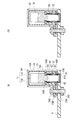
上記第一取付コネクタ60は、各部材を分離状態で示す図3そして中間コネクタ10と接続された状態を示す図4及び図5に見られるように、金属製で円筒状の第一受入端子61と、これを保持する電気絶縁材製のハウジング66と、上記第一受入端子61内に収められた金属製の弾性筒状部材62とを有しており、上記ハウジング66に形成された二つの保持孔67のそれぞれに上記第一受入端子61が収められ、さらに第一受入端子61内に弾性筒状部材62が収められている。図1〜5では、第一取付コネクタ60は水平に配された第一回路基板Pに取り付けられ、第二取付コネクタ70は縦方向に配された第二回路基板Qに取り付けられている。
The first mounting
第一受入端子61は図3にて上方に開口した円筒内面をもつ収容孔61Aが形成され、外周面は、段付きの円筒外面をなし、軸線方向中間位置に環状突部61Bを有している。上記収容孔61Aは、底部側に段状の環状当接部61C(図4(A)参照)が形成されており、弾性筒状部材62の軸線方向位置を定めている。上記収容孔61Aは、開口側内周面が中間コネクタ10の導電端子30である長端子31の第一接触部32そして短端子36の第一接触部37をそれぞれ導入するに好都合なテーパ内面をなしている。
The first receiving
上記第一受入端子61の収容孔61Aに収容される弾性筒状部材62は、図3に見られるように、金属板にスリット62Aを形成した後にこれを円筒状に丸める成形を施して形成されている。上記スリット62Aは、周方向の複数位置に、弾性筒状部材62の軸線Z1方向両端部の間で軸線方向に延びて形成されている。軸線方向両端部(周縁)は、スリットが及んでいないのでリング状をなしている。かかる弾性筒状部材62は、軸線方向中間位置に向け縮径加工を受けており、上記中間位置で環状くびれ部62Bを形成している。このように形成される弾性筒状部材62は、金属板にスリット62Aを形成後に環状くびれ部62Bを有するようにして円筒状に丸められる際、周方向で突き合わせられる当接部が隙間をもって当接可能に分離したままでも、あるいは互いに溶接等で接合されても良い。かかる弾性筒状部材62は、一時的に弾性縮径した状態で収容孔61Aに収められる。この弾性筒状部材62は、第一受入端子61の収容孔61Aに収容された後は、弾性力で原形に向け拡径して収容孔61Aの内面に弾性接触し、軸線方向では一端の周縁が、該収容孔61Aの底部側の環状当接部61Cに当接して位置が定められる。
As shown in FIG. 3, the elastic
上記第一受入端子61を保持するハウジング66は、図1〜5に見られるように、略直方体外形を有しており、上記第一受入端子61を収めて該第一受入端子61を保持する保持孔67が二箇所に形成されており、各保持孔67でそれぞれ同様に、第一受入端子61を保持している。ハウジング66は、図4そして図5に見られるように、保持孔67の上部側で該保持孔67の内周縁部に、半径方向内方に突出する内側環状突部66Aを有し、保持孔67の下部開口側から挿入される第一受入端子61の上端を規制している。また、上記ハウジングの下部開口の内周縁には環状段部66Bが形成されていて上記第一受入端子61の環状突部61Bが当接する。上記内側環状突部66Aの内周縁は導電端子30の第一接触部32,37が突入できる内径となっている。
As shown in FIGS. 1 to 5, the
かかる第一取付コネクタ60は、第一回路基板Pに取り付けられる。第一回路基板Pは、図4そして図5に見られるように、第一受入端子61の底部が貫通しない程度に進入するスルーホールP1が形成されており、該スルーホールP1の内面と第一回路基板Pの両面そして内部に形成された回路層が導通して設けられている。したがって、上記第一受入端子61の底部がスルーホールP1の内周面と僅かな隙間が形成され、この隙間に半田が流入して半田接続されて、第一受入端子61は回路層と電気的に接続され、第一回路基板Pへの取付けがなされる。
The
第二取付コネクタ70も、第一取付コネクタ60と同様に構成され、かつ同様に第二回路基板Qに接続かつ取り付けられる。
The
このようにして構成される、第一そして第二取付コネクタ60,70そして中間コネクタ10とは、次の要領で使用される。
The first and second mounting
先ず、図1のごとく、第一回路基板Pに第一取付コネクタ60を取り付けると共に第二回路基板Qに第二取付コネクタ70を取り付ける。次に、このように第一回路基板Pに取り付けられた第一取付コネクタ60を、該第一取付コネクタ60が上向きとなるように位置させてから、中間コネクタ10を上記第一取付コネクタ60の上方から降下せしめ、該中間コネクタ10の導電端子30の下端側、すなわち長端子31の第一接触部32そして短端子36の第一接触部37を第一取付コネクタ60の対応第一受入端子61に収められている弾性筒状部材62内に挿入させる。挿入をさらに進行させると、上記長端子31の第一接触部32と短端子36の第一接触部37は、それぞれ対応する弾性筒状部材62の環状くびれ部62Bを弾性拡径させながら降下して所定位置に達する。弾性拡径したそれぞれの弾性筒状部材62は、上記第一接触部32そして第一接触部37の外周面と弾性接触するとともに、第一受入端子61の収容孔61Aの内周面に対してその弾性接触圧を増大する。しかる後、ねじ24Aにより中間コネクタ10を第一回路基板Pに固定する。中間コネクタ10を第一回路基板Pから外したいときは、上記ねじ24Aを外した後に中間コネクタ10を上方にもち上げる。
First, as shown in FIG. 1, the
次に、第二回路基板Qに取り付けられている第二取付コネクタ70を、該第二取付コネクタ70が横向き(すなわち第二回路基板Qが縦向き)となるようにして、第一取付コネクタ60に接続されている中間コネクタ10に向け横方向から近接させ、中間コネクタ10の導電端子30、すなわち長端子31の第二接触部33そして短端子36の第二接触部38が第二取付コネクタ70の対応第二受入端子71内の弾性筒状部材72内に受け入れられる。かくして、中間コネクタ10は、上記第一取付コネクタ60に対するときと同様にして、第二取付コネクタ70に対しても接続される。この場合、中間コネクタ10は第二取付コネクタ70に対して固定されるねじを有していないので、第二取付コネクタ70は、横方向に引くだけで、中間コネクタ10との接続から開放される。このようにして、第一取付コネクタ60と第二取付コネクタ70は、上記中間コネクタ10を介して、いわゆるライトアングル接続される(図2及び図5(A)参照)。
Next, the
このように、中間コネクタ10を介して接続された第一取付コネクタ60と第二取付コネクタ70が、第一回路基板Pと第二回路基板Qにずれをもたらす外力あるいは傾きをもたす外力を受けたときに、これらの回路基板と共に、ずれて傾きを生ずるようになる。すなわち、第一回路基板Pと第二回路基板Qが当初の直角な相対姿勢を保っていても、回路基板の面同士が平行方向で相対的にずれればその分だけ導電端子30(長端子31そして短端子36)の第一接触部32,37と第二接触部33,38の間に傾きを生じるし、もちろん回路基板P,Q間に相対的に傾きが生ずれば、同様のこととなる。
In this way, the first mounting
図4(B)では、図3に示す軸線X(X1,X2)そしてZ(Z1,Z2)を参照すると、第二回路基板Qが正規の図4(A)の位置から第二接触部33,38(図3参照)の軸線X1,X2、すなわちXまわりに回転するように傾いた場合、図6では、上記第二回路基板Qが正規位置に対して上下方向(Z方向)にずれたときで、図6(A)では上方向にそして図6(B)では下方向にそれぞれずれたことにより第二接触部33,38が傾いた場合、図7では、第二回路基板Qが正規位置に対して、XZ平面に対して直角なY方向にずれたときで、図7(B)では、紙面に平行な面内で第二回路基板Qが図7(A)の正規位置から上方へずれたことにより第二接触部33(38)が傾いた場合である。このような傾きは、導電端子30である長端子31そして短端子36自体が変形せずに上述のような回路基板P,Q同士間の相対的なずれや傾きがある場合、さらには、導電端子30である長端子31そして短端子36の連結部34,39に弾性撓み変形を伴う場合のいずれの場合でも起き得る。なお、本実施形態では上記連結部34,39が弾性撓み変形しても、導電端子30である長端子31そして短端子36間に、ハウジング半体11A,11Bに設けられた突片19A,20A;19B,20Bが存在しているので、両端子31,36は互いに接触することはない。
4B, referring to the axes X (X1, X2) and Z (Z1, Z2) shown in FIG. 3, the second circuit board Q is moved from the normal position of FIG. , 38 (refer to FIG. 3), that is, when tilted to rotate around X, that is, around X, in FIG. 6, the second circuit board Q is displaced in the vertical direction (Z direction) with respect to the normal position. Sometimes, when the
このように、第一及び第二回路基板P,Q同士間での相対的なずれや傾きにより、第一接触部32,37や第二接触部33,38が第一受入端子61そして第二受入端子71に対して傾きを生ずる場合には、各図に見られるように、ずれが生じる前における導電端子の当初の軸線が受入端子の軸線に対して傾くようになる。この傾きは、第一取付コネクタ60の弾性筒状部材62と第二取付コネクタ70の弾性筒状部材72の半径方向の弾性変位により可能となる。両弾性筒状部材62,72の弾性変位は、それらの軸線まわりにおけるどの角度位置においても可能であり、同一力を受ければどの角度位置でも同一変位量であり、しかも、両弾性筒状部材62,72に互いに独立して弾性変位する。弾性筒状部材62,72は、周方向では、ずれが生じる角度位置で弾性変位量が最も大きく生ずるが、軸線方向では、それらの環状くびれ部62B,72Bの位置で弾性変位量が最も大きくなる。この環状くびれ部62B,72Bは、傾きが生ずる前には第一接触部32,37そして第二接触部33,38との間の接触線は円をなしているが、傾きが生じた状態では、その傾きにより接触線は楕円となる。しかしながら、図3のごとく、周方向の複数位置にスリット62A,72Aが形成されている弾性筒状部材62,72は、スリット同士間の細帯状部分がその板厚方向である半径方向に弾性変位しているので、第一接触部そして第二接触部に反力として作用する弾性力(圧力)は、どの細帯状部分でも軸線に向う半径方向に作用する。かくして、第一取付コネクタ60と第二取付コネクタ70は、既述の中間コネクタ10を介して、ライトアングル接続のもとでもフローティング状態が確保される。
As described above, the
本実施形態では、第一接触部と第二接触部とが直角な方向に延びて導電端子自体が全体としてL字状をなしている関係で、その内側に位置する端子が短くなっている。すなわち、内側に位置する短端子36は、例えば、第二回路基板Qのずれにより長端子31の第二接触部33の先端と短端子36の第二接触部38の先端とが同量だけ変位しても、第二接触部全長にわたる傾角という点で比較すると、短端子36の第二接触部38の方が角度が大きくなる。この影響を防止するために本実施形態では、短端子36の第二接触部38に環状溝部41が形成されていて、ハウジングとの対応部との当接による第二接触部の傾きに対する障害をなくしている。
In the present embodiment, since the first contact portion and the second contact portion extend in a direction perpendicular to each other and the conductive terminal itself has an L shape as a whole, the terminal located inside thereof is shortened. That is, the
本発明では、図1〜7の形態に限定されず、種々変更が可能である。例えば、図8のごとく、導電端子30をなす長端子31と短端子36とをその一部で、電気絶縁材の保持部材81で互いに保持しておくことが可能である。こうすることで、中間コネクタ10のハウジング11内での位置関係を維持できるだけでなく、ハウジング11に対する組立前における部材の保管、組立時の作業性において便宜である。
In this invention, it is not limited to the form of FIGS. 1-7, A various change is possible. For example, as shown in FIG. 8, the
さらには、図9のように、長端子31そして短端子36をばね部材82で支持することが好ましい。図9では、ハウジング半体11A,11Bの一部として弾性を有する薄片状のばね部材82A,82Bを形成し、このばね部材82A,82Bで長端子31の連結部34そして短端子36の連結部39をそれらの一部で上下から挟持支持している。こうすることで、連結部34そして連結部39について変位の自由度を確保しつつこれらを所定位置に支持することが可能となる。
Furthermore, it is preferable that the
10 中間コネクタ 62 弾性筒状部材
11A,11B ハウジング半体 62A スリット
30 導電端子 62B 環状くびれ部
32,37 第一接触部 70 第二取付コネクタ
33,38 第二接触部 71 第二受入端子
34,39 連結部 72 弾性筒状部材
60 第一取付コネクタ 81 保持部材
61 第一受入端子 82 ばね部材
10
30
Claims (6)
複数の導電端子は、接触部の軸線が互いに間隔をもつように配されており、一端に形成された第一接触部及び他端に形成された第二接触部と、第一及び第二接触部同士を連結する連結部とを有し、第一接触部の軸線と第二接触部の軸線が互いに交差するように上記連結部が屈曲成形されており、
導電端子の第一接触部及び第二接触部は、それぞれの軸線方向での移動、半径方向での移動そして軸線に対する傾斜の少なくとも一つが可能にハウジング内に収められており、
第一受入端子と導電端子の第一接触部との間、そして第二受入端子と導電端子の第二接触部との間に、それぞれの軸線まわりの周方向での任意角度位置で第一接触部そして第二接触部が傾きを生ずること及び半径方向に移動することを許容可能に半径方向で弾性変形可能な金属製の弾性筒状部材が設けられており、該弾性筒状部材が周面で第一接触部と第一受入端子もしくは第二接触部と第二受入端子との間で弾性変形状態のもとに接触することを特徴とする電気コネクタ組立体。 A first attachment connector attached to the first circuit member; a second attachment connector attached to the second circuit member; and a first attachment connector and a second interposed between the first attachment connector and the second attachment connector. An intermediate connector for connecting the mounting connector, the intermediate connector having a plurality of conductive terminals in the housing, wherein the first mounting connector and the second mounting connector are formed at corresponding end portions of the conductive terminals, respectively. In an electrical connector assembly comprising a first receiving terminal and a second receiving terminal, respectively, which receive a shaft-shaped contact portion in the axial direction thereof and contact the peripheral surface of the contact portion.
The plurality of conductive terminals are arranged such that the axes of the contact portions are spaced from each other , the first contact portion formed at one end, the second contact portion formed at the other end, and the first and second contacts A connecting part that connects the parts, and the connecting part is bent so that the axis of the first contact part and the axis of the second contact part intersect each other,
The first contact portion and the second contact portion of the conductive terminal are housed in the housing so that at least one of movement in the axial direction, movement in the radial direction, and inclination with respect to the axial line is possible.
Between the first contact portion of the first receiving terminal and the conductive terminal, and between the second contact portion of the second receiving terminal and the conductive terminal, the first contact at an arbitrary angular position in the circumferential direction about respective axes parts and acceptably resilient cylindrical member made of elastically deformable metal in the radial direction is provided is the elastic cylindrical member peripheral surface that the second contact portion moves to and radially causing inclination An electrical connector assembly, wherein the first contact portion and the first receiving terminal or the second contact portion and the second receiving terminal are in contact with each other under an elastically deformed state.
Priority Applications (3)
| Application Number | Priority Date | Filing Date | Title |
|---|---|---|---|
| JP2012275677A JP6103917B2 (en) | 2012-12-18 | 2012-12-18 | Electrical connector assembly |
| US14/101,649 US9147952B2 (en) | 2012-12-18 | 2013-12-10 | Electrical connector assembled component |
| CN201310699767.3A CN103872484B (en) | 2012-12-18 | 2013-12-18 | Electric connector assembly |
Applications Claiming Priority (1)
| Application Number | Priority Date | Filing Date | Title |
|---|---|---|---|
| JP2012275677A JP6103917B2 (en) | 2012-12-18 | 2012-12-18 | Electrical connector assembly |
Publications (2)
| Publication Number | Publication Date |
|---|---|
| JP2014120377A JP2014120377A (en) | 2014-06-30 |
| JP6103917B2 true JP6103917B2 (en) | 2017-03-29 |
Family
ID=50910763
Family Applications (1)
| Application Number | Title | Priority Date | Filing Date |
|---|---|---|---|
| JP2012275677A Active JP6103917B2 (en) | 2012-12-18 | 2012-12-18 | Electrical connector assembly |
Country Status (3)
| Country | Link |
|---|---|
| US (1) | US9147952B2 (en) |
| JP (1) | JP6103917B2 (en) |
| CN (1) | CN103872484B (en) |
Families Citing this family (27)
| Publication number | Priority date | Publication date | Assignee | Title |
|---|---|---|---|---|
| EP2875919A1 (en) * | 2013-11-22 | 2015-05-27 | Koninklijke Philips N.V. | Hair cutting appliance, receptacle and connector plug |
| USD741264S1 (en) * | 2014-07-22 | 2015-10-20 | Castle Creations, Inc. | Battery connector |
| USD740753S1 (en) * | 2014-07-24 | 2015-10-13 | Castle Creations, Inc. | Battery connector cover |
| US9673549B2 (en) * | 2014-12-17 | 2017-06-06 | Toyota Jidosha Kabushiki Kaisha | Connector with movement suppression function during excessive vibration |
| CN105742859A (en) * | 2016-04-08 | 2016-07-06 | 黄永怀 | Columnar electrical connector |
| JP6441259B2 (en) * | 2016-05-17 | 2018-12-19 | イリソ電子工業株式会社 | connector |
| DE102016213757B4 (en) * | 2016-07-27 | 2018-09-27 | Audi Ag | Plug-in connection for coupling high-voltage connections and system with such a connector |
| US9705244B1 (en) * | 2016-12-20 | 2017-07-11 | Amphenol East Asia Electronic Technology (Shen Zhen) Co., Ltd. | Electric connector |
| KR102662704B1 (en) * | 2017-01-18 | 2024-05-02 | 삼성에스디아이 주식회사 | Manual Service Disconnect for Battery System |
| CN106953188B (en) * | 2017-02-21 | 2023-12-05 | 中航光电科技股份有限公司 | Switching connector |
| CN206712064U (en) * | 2017-05-25 | 2017-12-05 | 莫列斯有限公司 | High current connector and high current attachment means |
| JP6415654B1 (en) * | 2017-07-28 | 2018-10-31 | イリソ電子工業株式会社 | Electronic components |
| DE102017218326A1 (en) | 2017-10-13 | 2019-04-18 | Robert Bosch Gmbh | High current connection |
| DE102018118405B3 (en) * | 2018-07-30 | 2019-12-05 | Ims Connector Systems Gmbh | Connector and plug connection with such a connector |
| KR102573668B1 (en) * | 2018-09-17 | 2023-09-06 | 삼성전자 주식회사 | Electrical connector and electronic device including the same |
| JP7024741B2 (en) * | 2019-01-31 | 2022-02-24 | 株式会社オートネットワーク技術研究所 | Connector and connector connection structure |
| KR102765217B1 (en) * | 2019-02-13 | 2025-02-11 | 타이코에이엠피 주식회사 | Connector and connector assembly comprising the same |
| CN209298384U (en) * | 2019-03-04 | 2019-08-23 | 台达电子企业管理(上海)有限公司 | Universal power input component |
| CN110350330B (en) * | 2019-07-17 | 2020-09-15 | 上海航天科工电器研究院有限公司 | Elastic structure for connecting socket and PCB |
| CN110581391A (en) * | 2019-09-19 | 2019-12-17 | 上海航天科工电器研究院有限公司 | Quick-locking piston type floating power connector |
| EP3843219A1 (en) | 2019-12-23 | 2021-06-30 | ODU GmbH & Co. KG | Adaptive connector |
| EP3843222B1 (en) * | 2019-12-24 | 2025-02-26 | Fico Triad, S.A. | Electrical connector |
| CN111463615B (en) * | 2020-04-08 | 2021-08-06 | 东莞立讯技术有限公司 | Wire Ends, Board Ends and Connectors |
| CN112151992B (en) * | 2020-08-11 | 2022-05-31 | 上海航天科工电器研究院有限公司 | Floating connection structure |
| KR102651499B1 (en) * | 2021-08-20 | 2024-03-27 | 현대모비스 주식회사 | Bidirectional signal pin module, power module including the same and manufacturing method thereof |
| US20230087891A1 (en) * | 2021-09-23 | 2023-03-23 | Apple Inc. | Pass-through connectors for connector systems |
| KR102515427B1 (en) * | 2022-09-08 | 2023-03-29 | 장문석 | Power connector with variable pins |
Family Cites Families (37)
| Publication number | Priority date | Publication date | Assignee | Title |
|---|---|---|---|---|
| JPS57127491U (en) * | 1981-02-02 | 1982-08-09 | ||
| US4764121A (en) * | 1985-12-16 | 1988-08-16 | Telephone Products, Inc. | Rotary electrical connector |
| US4749357A (en) * | 1985-12-23 | 1988-06-07 | Elcon Products International Company | Circuit board connector, bus and system |
| US5055055A (en) * | 1990-10-12 | 1991-10-08 | Elcon Products International Company | Circuit board connector system |
| JPH04112482U (en) * | 1991-03-20 | 1992-09-30 | 株式会社日立製作所 | buffer connector |
| JP2910505B2 (en) * | 1993-04-27 | 1999-06-23 | 住友電装株式会社 | Connector device |
| JP2717937B2 (en) * | 1994-10-31 | 1998-02-25 | 日本航空電子工業株式会社 | Connector with floating adapter |
| US5567170A (en) * | 1994-12-07 | 1996-10-22 | Camco International Inc. | Plug-in pothead |
| EP0760542B1 (en) * | 1995-08-26 | 2002-02-27 | Molex Incorporated | Electrical connector with improved latching system |
| US5807120A (en) * | 1996-03-06 | 1998-09-15 | Elcon Products International | Printed circuit board power distribution connector |
| JP3747964B2 (en) * | 1996-07-26 | 2006-02-22 | 株式会社フジクラ | Alignment connector |
| US5823812A (en) * | 1996-08-08 | 1998-10-20 | Symbol Technologies, Inc. | Electrical connector |
| DE29713333U1 (en) * | 1997-07-26 | 1997-09-18 | Hewlett-Packard Co., Palo Alto, Calif. | Electrical safety plug connection for direct and wire-based contacting |
| US6062919A (en) * | 1997-08-29 | 2000-05-16 | Thomas & Betts International, Inc. | Electrical connector assembly having high current-carrying capability and low insertion force |
| US6036506A (en) * | 1998-03-18 | 2000-03-14 | The Whitaker Corporation | Right angle electrical connector |
| US6280245B1 (en) * | 1999-09-17 | 2001-08-28 | Tvm Group, Inc. | Dual contact power connector |
| CN2411594Y (en) * | 2000-01-24 | 2000-12-20 | 建舜电子制造股份有限公司 | Corner-right angle connector |
| DE10013823C1 (en) * | 2000-03-21 | 2002-01-03 | Fci Automotive Deutschland Gmb | Electrical connector plug has locking lugs to act on specified lug so that spring develops tension with swell point, when specified connector moves in insertion direction |
| US6656002B2 (en) * | 2000-09-15 | 2003-12-02 | Alcoa Fujikura Limited | Electrical terminal socket assembly including T shaped sealed connectors |
| US6875063B2 (en) * | 2000-09-15 | 2005-04-05 | Alcoa Fujikura Limited | Electrical terminal socket assembly including both T shaped and 90° angled and sealed connectors |
| JP4401915B2 (en) * | 2004-09-21 | 2010-01-20 | 矢崎総業株式会社 | Connector with liquid intrusion prevention structure |
| US20060094281A1 (en) * | 2004-11-04 | 2006-05-04 | Carlyle, Inc. | Latching electrical connector assembly |
| JP2007173198A (en) * | 2005-11-25 | 2007-07-05 | Hitachi Cable Ltd | Electrical contact and female terminal |
| US7407413B2 (en) * | 2006-03-03 | 2008-08-05 | Fci Americas Technology, Inc. | Broadside-to-edge-coupling connector system |
| DE102006013281B4 (en) * | 2006-03-21 | 2024-04-04 | Erni Production Gmbh & Co. Kg | Plug connection adapter |
| US7494374B2 (en) * | 2007-02-01 | 2009-02-24 | Tyco Electronics Corporation | Panel mount electrical connector |
| US20080299811A1 (en) * | 2007-05-30 | 2008-12-04 | Battista Paul F | Power inlets and power connectors |
| US7601019B2 (en) * | 2007-06-22 | 2009-10-13 | Delphi Technologies, Inc. | Electrical connection system |
| US7530830B1 (en) * | 2007-07-19 | 2009-05-12 | Sunpower Corporation | Misalignment tolerant connector |
| JP4767923B2 (en) * | 2007-07-27 | 2011-09-07 | タイコエレクトロニクスジャパン合同会社 | Electrical connector and connector assembly |
| CN101447618B (en) * | 2007-11-27 | 2011-12-21 | 贵州航天电器股份有限公司 | High-speed high-density electric connector socket used for differential signal transmission |
| EP2487758B1 (en) * | 2009-01-20 | 2014-10-08 | ODU GmbH & Co KG. | Electrical connector for high-temperature environments |
| US8029326B2 (en) * | 2009-07-28 | 2011-10-04 | Tyco Electronics Corporation | Electrical connector having an electrical contact with a contact arm |
| JP2011060732A (en) | 2009-09-14 | 2011-03-24 | Japan Aviation Electronics Industry Ltd | Connector |
| TW201203711A (en) * | 2010-06-17 | 2012-01-16 | Asustek Comp Inc | Connector module and connector |
| US8202105B2 (en) * | 2010-07-21 | 2012-06-19 | Tyco Electronics Corporation | Electrical connector with floating contact |
| JP5462231B2 (en) * | 2011-10-24 | 2014-04-02 | ヒロセ電機株式会社 | Electrical connector assembly |
-
2012
- 2012-12-18 JP JP2012275677A patent/JP6103917B2/en active Active
-
2013
- 2013-12-10 US US14/101,649 patent/US9147952B2/en active Active
- 2013-12-18 CN CN201310699767.3A patent/CN103872484B/en not_active Expired - Fee Related
Also Published As
| Publication number | Publication date |
|---|---|
| CN103872484B (en) | 2017-12-08 |
| CN103872484A (en) | 2014-06-18 |
| JP2014120377A (en) | 2014-06-30 |
| US9147952B2 (en) | 2015-09-29 |
| US20140170886A1 (en) | 2014-06-19 |
Similar Documents
| Publication | Publication Date | Title |
|---|---|---|
| JP6103917B2 (en) | Electrical connector assembly | |
| JP6041107B2 (en) | Coaxial connector with floating mechanism | |
| EP3249752B1 (en) | Connecting structure | |
| JP5462231B2 (en) | Electrical connector assembly | |
| US20170170588A1 (en) | Electrical connector | |
| US9502815B2 (en) | Electrical connector | |
| US20160064877A1 (en) | Connector | |
| TWI530036B (en) | Connectors and performance boards, motherboards, and semiconductor test devices including the connector | |
| US10622743B2 (en) | Terminal module with a conductive obliquely wound coil spring held against an electrical contact member and connector having such a terminal module | |
| US9912089B2 (en) | Electrical connector having a female terminal with a holding protrusion | |
| JP5858024B2 (en) | Coaxial connector plug | |
| JP2022186850A (en) | movable connector | |
| US20150017823A1 (en) | Connector | |
| JP4933325B2 (en) | Connection terminal structure | |
| JP6681655B2 (en) | Coaxial connector | |
| JP2017050269A (en) | connector | |
| JP2019185961A (en) | BNC connector plug and BNC connector | |
| JP6724674B2 (en) | Surface mount connector | |
| JP6376966B2 (en) | connector | |
| JP2018063771A (en) | connector | |
| JP2016207533A (en) | Connector support structure | |
| JP2016146294A (en) | Male and female connectors |
Legal Events
| Date | Code | Title | Description |
|---|---|---|---|
| A621 | Written request for application examination |
Free format text: JAPANESE INTERMEDIATE CODE: A621 Effective date: 20151124 |
|
| A977 | Report on retrieval |
Free format text: JAPANESE INTERMEDIATE CODE: A971007 Effective date: 20160707 |
|
| A131 | Notification of reasons for refusal |
Free format text: JAPANESE INTERMEDIATE CODE: A131 Effective date: 20160714 |
|
| A521 | Request for written amendment filed |
Free format text: JAPANESE INTERMEDIATE CODE: A523 Effective date: 20160912 |
|
| TRDD | Decision of grant or rejection written | ||
| A01 | Written decision to grant a patent or to grant a registration (utility model) |
Free format text: JAPANESE INTERMEDIATE CODE: A01 Effective date: 20170214 |
|
| A61 | First payment of annual fees (during grant procedure) |
Free format text: JAPANESE INTERMEDIATE CODE: A61 Effective date: 20170228 |
|
| R150 | Certificate of patent or registration of utility model |
Ref document number: 6103917 Country of ref document: JP Free format text: JAPANESE INTERMEDIATE CODE: R150 |
|
| R250 | Receipt of annual fees |
Free format text: JAPANESE INTERMEDIATE CODE: R250 |
|
| S531 | Written request for registration of change of domicile |
Free format text: JAPANESE INTERMEDIATE CODE: R313531 |
|
| R350 | Written notification of registration of transfer |
Free format text: JAPANESE INTERMEDIATE CODE: R350 |
|
| R250 | Receipt of annual fees |
Free format text: JAPANESE INTERMEDIATE CODE: R250 |
|
| R250 | Receipt of annual fees |
Free format text: JAPANESE INTERMEDIATE CODE: R250 |
|
| R250 | Receipt of annual fees |
Free format text: JAPANESE INTERMEDIATE CODE: R250 |
|
| R250 | Receipt of annual fees |
Free format text: JAPANESE INTERMEDIATE CODE: R250 |
|
| R250 | Receipt of annual fees |
Free format text: JAPANESE INTERMEDIATE CODE: R250 |