JP6092190B2 - Multidirectional catheter control handle - Google Patents
Multidirectional catheter control handle Download PDFInfo
- Publication number
- JP6092190B2 JP6092190B2 JP2014510303A JP2014510303A JP6092190B2 JP 6092190 B2 JP6092190 B2 JP 6092190B2 JP 2014510303 A JP2014510303 A JP 2014510303A JP 2014510303 A JP2014510303 A JP 2014510303A JP 6092190 B2 JP6092190 B2 JP 6092190B2
- Authority
- JP
- Japan
- Prior art keywords
- pair
- slide
- adjustment knob
- deflection
- slide members
- Prior art date
- Legal status (The legal status is an assumption and is not a legal conclusion. Google has not performed a legal analysis and makes no representation as to the accuracy of the status listed.)
- Active
Links
- 230000033001 locomotion Effects 0.000 claims description 18
- 238000006073 displacement reaction Methods 0.000 claims description 12
- 230000006835 compression Effects 0.000 claims description 5
- 238000007906 compression Methods 0.000 claims description 5
- 230000005540 biological transmission Effects 0.000 claims 8
- 230000002093 peripheral effect Effects 0.000 description 13
- 238000000034 method Methods 0.000 description 11
- 238000013507 mapping Methods 0.000 description 6
- 230000007935 neutral effect Effects 0.000 description 6
- 230000008901 benefit Effects 0.000 description 5
- 238000012800 visualization Methods 0.000 description 5
- 238000005516 engineering process Methods 0.000 description 3
- 230000007246 mechanism Effects 0.000 description 3
- 229910000679 solder Inorganic materials 0.000 description 3
- DIDGPCDGNMIUNX-UUOKFMHZSA-N 2-amino-9-[(2r,3r,4s,5r)-5-(dihydroxyphosphinothioyloxymethyl)-3,4-dihydroxyoxolan-2-yl]-3h-purin-6-one Chemical compound C1=2NC(N)=NC(=O)C=2N=CN1[C@@H]1O[C@H](COP(O)(O)=S)[C@@H](O)[C@H]1O DIDGPCDGNMIUNX-UUOKFMHZSA-N 0.000 description 2
- 238000002679 ablation Methods 0.000 description 2
- 230000008878 coupling Effects 0.000 description 2
- 238000010168 coupling process Methods 0.000 description 2
- 238000005859 coupling reaction Methods 0.000 description 2
- 230000003993 interaction Effects 0.000 description 2
- 238000005476 soldering Methods 0.000 description 2
- 238000001356 surgical procedure Methods 0.000 description 2
- 238000002560 therapeutic procedure Methods 0.000 description 2
- 210000001835 viscera Anatomy 0.000 description 2
- 229920000914 Metallic fiber Polymers 0.000 description 1
- 239000004677 Nylon Substances 0.000 description 1
- 229910000831 Steel Inorganic materials 0.000 description 1
- 230000009471 action Effects 0.000 description 1
- 230000002411 adverse Effects 0.000 description 1
- 238000013459 approach Methods 0.000 description 1
- 239000005441 aurora Substances 0.000 description 1
- 238000005452 bending Methods 0.000 description 1
- 230000000747 cardiac effect Effects 0.000 description 1
- 239000000356 contaminant Substances 0.000 description 1
- 239000002872 contrast media Substances 0.000 description 1
- 230000003247 decreasing effect Effects 0.000 description 1
- 230000002439 hemostatic effect Effects 0.000 description 1
- 238000002347 injection Methods 0.000 description 1
- 239000007924 injection Substances 0.000 description 1
- 238000009434 installation Methods 0.000 description 1
- 230000004807 localization Effects 0.000 description 1
- 239000000463 material Substances 0.000 description 1
- 238000012806 monitoring device Methods 0.000 description 1
- 238000012544 monitoring process Methods 0.000 description 1
- 229920001778 nylon Polymers 0.000 description 1
- 210000000056 organ Anatomy 0.000 description 1
- 229920001296 polysiloxane Polymers 0.000 description 1
- 229920002635 polyurethane Polymers 0.000 description 1
- 239000004814 polyurethane Substances 0.000 description 1
- 230000003014 reinforcing effect Effects 0.000 description 1
- 239000010959 steel Substances 0.000 description 1
- 210000003462 vein Anatomy 0.000 description 1
- 238000004804 winding Methods 0.000 description 1
Images


Classifications
-
- A—HUMAN NECESSITIES
- A61—MEDICAL OR VETERINARY SCIENCE; HYGIENE
- A61M—DEVICES FOR INTRODUCING MEDIA INTO, OR ONTO, THE BODY; DEVICES FOR TRANSDUCING BODY MEDIA OR FOR TAKING MEDIA FROM THE BODY; DEVICES FOR PRODUCING OR ENDING SLEEP OR STUPOR
- A61M25/00—Catheters; Hollow probes
- A61M25/01—Introducing, guiding, advancing, emplacing or holding catheters
- A61M25/0105—Steering means as part of the catheter or advancing means; Markers for positioning
- A61M25/0133—Tip steering devices
- A61M25/0147—Tip steering devices with movable mechanical means, e.g. pull wires
-
- A—HUMAN NECESSITIES
- A61—MEDICAL OR VETERINARY SCIENCE; HYGIENE
- A61B—DIAGNOSIS; SURGERY; IDENTIFICATION
- A61B5/00—Measuring for diagnostic purposes; Identification of persons
- A61B5/24—Detecting, measuring or recording bioelectric or biomagnetic signals of the body or parts thereof
- A61B5/25—Bioelectric electrodes therefor
- A61B5/279—Bioelectric electrodes therefor specially adapted for particular uses
- A61B5/28—Bioelectric electrodes therefor specially adapted for particular uses for electrocardiography [ECG]
- A61B5/283—Invasive
-
- A—HUMAN NECESSITIES
- A61—MEDICAL OR VETERINARY SCIENCE; HYGIENE
- A61M—DEVICES FOR INTRODUCING MEDIA INTO, OR ONTO, THE BODY; DEVICES FOR TRANSDUCING BODY MEDIA OR FOR TAKING MEDIA FROM THE BODY; DEVICES FOR PRODUCING OR ENDING SLEEP OR STUPOR
- A61M25/00—Catheters; Hollow probes
- A61M25/01—Introducing, guiding, advancing, emplacing or holding catheters
- A61M25/0105—Steering means as part of the catheter or advancing means; Markers for positioning
- A61M25/0133—Tip steering devices
- A61M25/0136—Handles therefor
-
- A—HUMAN NECESSITIES
- A61—MEDICAL OR VETERINARY SCIENCE; HYGIENE
- A61B—DIAGNOSIS; SURGERY; IDENTIFICATION
- A61B17/00—Surgical instruments, devices or methods
- A61B17/00234—Surgical instruments, devices or methods for minimally invasive surgery
- A61B2017/00292—Surgical instruments, devices or methods for minimally invasive surgery mounted on or guided by flexible, e.g. catheter-like, means
- A61B2017/003—Steerable
- A61B2017/00318—Steering mechanisms
- A61B2017/00323—Cables or rods
- A61B2017/00327—Cables or rods with actuating members moving in opposite directions
Landscapes
- Health & Medical Sciences (AREA)
- Life Sciences & Earth Sciences (AREA)
- Engineering & Computer Science (AREA)
- Animal Behavior & Ethology (AREA)
- Veterinary Medicine (AREA)
- Biophysics (AREA)
- Public Health (AREA)
- Biomedical Technology (AREA)
- Heart & Thoracic Surgery (AREA)
- General Health & Medical Sciences (AREA)
- Pulmonology (AREA)
- Hematology (AREA)
- Anesthesiology (AREA)
- Mechanical Engineering (AREA)
- Cardiology (AREA)
- Physics & Mathematics (AREA)
- Pathology (AREA)
- Medical Informatics (AREA)
- Molecular Biology (AREA)
- Surgery (AREA)
- Media Introduction/Drainage Providing Device (AREA)
- Surgical Instruments (AREA)
Description
(関連出願の相互参照)
本願は、2011年5月11日に出願され、2010年5月11日に出願された米国仮出願第61/333,641の利益を主張する米国特許出願第13/105,646に対する優先権を主張する。これらの出願は、全体として本明細書に示されたかのように、参照により本明細書に組み込まれる。
(Cross-reference of related applications)
This application claims priority to US patent application No. 13 / 105,646, filed May 11, 2011, and claiming the benefit of US Provisional Application No. 61 / 333,641 filed May 11, 2010. Insist. These applications are hereby incorporated by reference as if set forth herein in their entirety.
本開示は、カテーテルおよびその他の操作可能な医療機器に関する。より具体的には、本開示は、操縦可能なカテーテルおよびその他の操作可能な医療機器用のための多方向性制御ハンドルに関する。 The present disclosure relates to catheters and other operable medical devices. More specifically, the present disclosure relates to multidirectional control handles for steerable catheters and other steerable medical devices.
偏向可能な遠位端部を備える可撓性チューブ状本体と、遠位端部の偏向制御用の制御ハンドルとを有するカテーテル(すなわち、カテーテルまたはシース)が、多くの非侵襲的な医療処置に使用される。例えば、心臓内の電気生理学的研究には、一般的に、本体の遠位端部に沿って導電性電極を有するカテーテルが使用される。カテーテル本体の遠位端部は、一般に患者の心臓に配置されて、電気生理学的研究の最中または心臓内マッピングの最中、心臓内の電気信号を監視および/または記録する。遠位端部の向きまたは構成は、患者の体外に留まるカテーテルの制御ハンドルに配置されたアクチュエータによって制御される。電極は、心臓の電気信号を、制御ハンドルに作動的に接続された適切な監視・記録装置に伝達する。 A catheter (ie, catheter or sheath) having a flexible tubular body with a deflectable distal end and a control handle for deflection control of the distal end is useful for many non-invasive medical procedures. used. For example, electrophysiological studies within the heart typically use a catheter having a conductive electrode along the distal end of the body. The distal end of the catheter body is typically placed on the patient's heart to monitor and / or record electrical signals within the heart during electrophysiological studies or intracardiac mapping. The orientation or configuration of the distal end is controlled by an actuator located on the control handle of the catheter that remains outside the patient's body. The electrodes transmit cardiac electrical signals to a suitable monitoring and recording device operatively connected to the control handle.
一般に、カテーテル本体はシリンダー状であり、かつ電気的に非導電性である。カテーテル本体は、ポリウレタン、ナイロンまたは他の電気的に非導電性の可撓性材料から構成された可撓性チューブを含む。カテーテル本体は、さらに、補強要素として壁に編組の鋼線またはその他の非金属性繊維を含む。各電極は、それらに取り付けられかつカテーテル本体にわたって延在する比較的細い導電性線を有する。導電性線は、遠位端部から近位端部まで延在し、近位端部には、プラグや電気ジャックなどの電気コネクタが設けられ、記録または監視装置に設けられた対応するソケットに差し込まれる。 In general, the catheter body is cylindrical and electrically non-conductive. The catheter body includes a flexible tube constructed from polyurethane, nylon or other electrically non-conductive flexible material. The catheter body further includes braided steel wire or other non-metallic fibers on the wall as a reinforcing element. Each electrode has a relatively thin conductive wire attached to them and extending across the catheter body. The conductive wire extends from the distal end to the proximal end, where the proximal end is provided with an electrical connector, such as a plug or an electrical jack, to a corresponding socket provided on the recording or monitoring device. Plugged in.
カテーテル本体の遠位部分は、制御ハンドルにあるアクチュエータを使用して様々な湾曲した構成に選択的に変形される。アクチュエータは、少なくとも1つの偏向ワイヤによってカテーテル本体の遠位部分に一般に内部結合されている。一部のカテーテル本体は単一の偏向ワイヤを用い、この偏向ワイヤは、アクチュエータによって引っ張られて(すなわち、張力がかけられて)、カテーテル本体の遠位部分を変形させる。他のカテーテル本体は少なくとも2つの偏向ワイヤを有し、一方のワイヤを変位させると(すなわち、一方のワイヤに張力をかけると)、他方のワイヤが弛むようになる(すなわち、このワイヤは圧縮荷重を担わない)。そのようなカテーテルでは、偏向ワイヤが圧縮荷重を担わないように適合される場合(すなわち、偏向ワイヤには張力がかけられるだけである)、偏向ワイヤは、一般にプルワイヤまたは張力ワイヤと呼ばれる。 The distal portion of the catheter body is selectively deformed to various curved configurations using an actuator on the control handle. The actuator is generally internally coupled to the distal portion of the catheter body by at least one deflection wire. Some catheter bodies use a single deflection wire that is pulled (ie, tensioned) by an actuator to deform the distal portion of the catheter body. The other catheter body has at least two deflection wires, and when one wire is displaced (ie, when one wire is tensioned), the other wire becomes loose (ie, this wire carries a compressive load). Not bear). In such catheters, if the deflection wire is adapted not to carry a compressive load (ie, the deflection wire is only tensioned), the deflection wire is commonly referred to as a pull wire or tension wire.
カテーテル本体の遠位端部を様々な構成に変形するために、最近のカテーテル設計では、一対の偏向ワイヤを用いており、それらは、偏向ワイヤの一方が張力を担うときに他方の偏向ワイヤが圧縮力を担うように適合されている。そのようなカテーテルでは、偏向ワイヤが圧縮荷重および引張荷重の双方を担うように適合される場合、偏向ワイヤは、一般にプッシュ/プルワイヤまたは張力/圧縮ワイヤと呼ばれ、および対応するカテーテルアクチュエータは、プッシュ/プルアクチュエータと呼ばれる。 In order to transform the distal end of the catheter body into various configurations, recent catheter designs use a pair of deflection wires, which can be used when one of the deflection wires bears tension. It is adapted to bear the compressive force. In such catheters, if the deflection wire is adapted to carry both compressive and tensile loads, the deflection wire is commonly referred to as a push / pull wire or tension / compression wire and the corresponding catheter actuator is a push / Pull actuator.
カテーテル本体の遠位端部の偏向を制御するための従来技術の制御ハンドルには、操作されるハンドルの能力に悪影響を及ぼすいくつかの欠点がある。第1に、制御ハンドルは、嵩張り過ぎることが多い。第2に、制御ハンドルは、カテーテル本体の遠位端部を精密に制御して偏向調整する能力に関して不十分であることが多い。第3に、制御ハンドルは、所望の医療処置に対して不適切な偏向ワイヤの移動をもたらすことが多い。第4に、制御ハンドルは、機械的利点が望ましい水準よりも低いことが多く、その結果、動かすためには使用者の方で著しい努力をすることが求められる。第5に、本体の遠位端部の所望の偏向に達したら、制御ハンドルは、一般に、医師に、カテーテルが所望の偏向を維持するような意識的なステップをとるよう要求する。第6に、制御ハンドル内のワイヤ変位メカニズムは、偏向ワイヤを永久的に変形させる傾向がある。第7に、制御ハンドル内のワイヤ変位メカニズムは、一般に、不可能ではないにしても、制御ハンドルの近位端部からカテーテル本体の遠位端部まで途切れることなく延びるルーメンを提供することを困難にする。 Prior art control handles for controlling the deflection of the distal end of the catheter body have several drawbacks that adversely affect the ability of the handle to be manipulated. First, the control handle is often too bulky. Second, control handles are often inadequate with respect to the ability to precisely control and adjust the distal end of the catheter body. Third, the control handle often results in movement of the deflection wire that is inappropriate for the desired medical procedure. Fourth, the control handle often has a mechanical advantage below the desired level, and as a result requires significant effort on the part of the user to move. Fifth, once the desired deflection of the distal end of the body is reached, the control handle generally requires the physician to take conscious steps such that the catheter maintains the desired deflection. Sixth, the wire displacement mechanism in the control handle tends to permanently deform the deflection wire. Seventh, wire displacement mechanisms within the control handle are generally difficult, if not impossible, to provide a lumen that extends uninterrupted from the proximal end of the control handle to the distal end of the catheter body. To.
それゆえ、上記の問題の1つ以上を最小にするまたは除去するカテーテルが必要とされている。 Therefore, there is a need for a catheter that minimizes or eliminates one or more of the above problems.
自動化され、コンピュータ化され、かつ電気的な医療技術の進歩にもかかわらず、多くの医師およびその他の医療の専門家は、患者内でカテーテルやその他の可撓性の細長い部材を操作するために、機械的なハンドルを好むと明言し続けている。本開示は、単独で使用されても、または他の医療技術と併用されてもよい、そのような大部分が機械的な多方向性カテーテル制御ハンドルの一つを考慮している。特に、多方向性カテーテル制御ハンドルの一実施形態は、支持部材、可撓性の細長い部材、第1および第2の対の偏向ワイヤ、および第1および第2の調整ノブを含み得る。 Despite advances in automated, computerized, and electrical medical technology, many physicians and other medical professionals are able to manipulate catheters and other flexible elongated members within a patient. Continue to state that he prefers mechanical handles. The present disclosure contemplates one such largely multi-directional catheter control handle that may be used alone or in combination with other medical techniques. In particular, one embodiment of a multi-directional catheter control handle may include a support member, a flexible elongate member, a first and second pair of deflection wires, and first and second adjustment knobs.
支持部材は、長手方向軸に沿って延在し、かつ制御ハンドルの様々な構成要素を支持するための構造的枠組みを提供し得る。一部の例ではカテーテル本体またはシースとし得る可撓性の細長い部材は、近位部分および遠位部分を有し得る。近位部分は、支持部材内に延在し得るか、またはそれに全体的に結合し得る。可撓性の細長い部材の遠位部分は、支持部材または制御ハンドルから最も離れている可撓性の細長い部材の部分を指すことが多い。さらに、可撓性の細長い部材の遠位部分は、一般に、治療を実施する、アブレーションを行う、内部器官をマッピングするなどのために、少なくとも1つの電極、超音波ファンなどを支持する医療機器の部分である。 The support member may extend along the longitudinal axis and provide a structural framework for supporting various components of the control handle. A flexible elongate member, which may be a catheter body or sheath in some examples, may have a proximal portion and a distal portion. The proximal portion can extend into the support member or can be generally coupled thereto. The distal portion of the flexible elongate member often refers to the portion of the flexible elongate member that is furthest away from the support member or control handle. In addition, the distal portion of the flexible elongate member generally includes a medical device that supports at least one electrode, ultrasonic fan, etc., for performing therapy, performing ablation, mapping internal organs, and the like. Part.
第1および第2の対の偏向ワイヤは、可撓性の細長い部材の遠位部分および第1および第2の調整ノブの双方に動作可能に結合され得る。例えば、第1の対の偏向ワイヤは第1の調整ノブに動作可能に結合され、および第2の対の偏向ワイヤは第2の調整ノブに動作可能に結合され得る。第1および第2の調整ノブは、支持部材に回転可能に結合されて、各調整ノブが支持部材の長手方向軸の周りで回転できるようにし得る。 The first and second pairs of deflection wires may be operatively coupled to both the distal portion of the flexible elongate member and the first and second adjustment knobs. For example, a first pair of deflection wires can be operably coupled to a first adjustment knob, and a second pair of deflection wires can be operably coupled to a second adjustment knob. The first and second adjustment knobs may be rotatably coupled to the support member to allow each adjustment knob to rotate about the longitudinal axis of the support member.
さらに、一実施形態では、これら偏向ワイヤは、可撓性の細長い部材およびその遠位部分の周りまたはそれらの内部において、ほぼ直角の構成に方向付けられ得る。従って、第1の調整ノブの回転により、遠位部分を左右に偏向させる一方、第2の調整ノブの回転により、遠位部分を前後方向に偏向させ得る。そのためには、第1の調整ノブを回転させるとき、第1の対の偏向ワイヤの1つに張力がかけられて、遠位部分の片側を引っ張って、右に動くようにし得る。第1の調整ノブが異なる方向に回転される場合、第1の対の偏向ワイヤの他方の偏向ワイヤに張力がかけられて、遠位部分の反対側を引っ張って、左に動くようにし得る。同様に、第2の調整ノブを回転させるとき、第2の対の偏向ワイヤの1つに張力がかけられて、遠位部分の別の側を引っ張って、前方に動くようにし得る。第2の調整ノブが異なる方向に回転される場合、第2の対の偏向ワイヤの他方の偏向ワイヤに張力がかけられて、遠位部分のさらに異なる別の側を引っ張って、後方に動くようにし得る。 Further, in one embodiment, the deflection wires can be oriented in a substantially right angle configuration around or within the flexible elongate member and its distal portion. Accordingly, the distal portion can be deflected left and right by the rotation of the first adjustment knob, while the distal portion can be deflected in the front-rear direction by the rotation of the second adjustment knob. To do so, when rotating the first adjustment knob, one of the first pair of deflection wires can be tensioned and pulled on one side of the distal portion to move to the right. When the first adjustment knob is rotated in a different direction, the other deflection wire of the first pair of deflection wires can be tensioned and pulled opposite the distal portion to move to the left. Similarly, when rotating the second adjustment knob, one of the second pair of deflection wires can be tensioned to pull the other side of the distal portion to move forward. When the second adjustment knob is rotated in a different direction, the other deflection wire of the second pair of deflection wires is tensioned to pull further on another side of the distal portion to move backwards. Can be.
一実施形態では、多方向性カテーテル制御ハンドルは、偏向ワイヤを変位させるために、第1および第2の対のスライド部材を含み得る。スライド部材は、支持部材に沿って全体的に軸方向に変位可能とし得る。さらに、第1の対のスライド部材は、第1の対の偏向ワイヤを第1の調整ノブに動作可能に結合し得る一方、第2の対のスライド部材は、第2の対の偏向ワイヤを第2の調整ノブに動作可能に結合し得る。さらにまた、一実施形態では、第1の対のスライド部材の一方が右ねじを有し得る一方、第1の対のスライド部材の他方が左ねじを有し得る。第2の対のスライド部材でも同様とし得る。右および左雌ねじの双方を調整ノブ内に配置して、スライド部材の右および左雄ねじの双方と係合させ得る。それゆえ、第1の調整ノブを回転させると、第1の対のスライド部材は反対方向に動き、それにより第1の対の偏向ワイヤの一方に張力をかけ、かつそれにより、第1の対の偏向ワイヤの他方の偏向ワイヤの張力を全て解放する。それゆえ、第2の調整ノブを回転させると、第2の対のスライド部材は反対方向に動き、それにより第2の対の偏向ワイヤの一方に張力をかけ、かつそれにより、第2の対の偏向ワイヤの他方の偏向ワイヤの張力を全て解放する。 In one embodiment, the multi-directional catheter control handle may include a first and second pair of slide members for displacing the deflection wire. The slide member may be axially displaceable generally along the support member. Further, the first pair of slide members may operably couple the first pair of deflection wires to the first adjustment knob, while the second pair of slide members may couple the second pair of deflection wires. A second adjustment knob may be operatively coupled. Furthermore, in one embodiment, one of the first pair of slide members may have a right-hand thread, while the other of the first pair of slide members may have a left-hand thread. The same applies to the second pair of slide members. Both right and left female threads can be placed in the adjustment knob to engage both the right and left male threads of the slide member. Therefore, when the first adjustment knob is rotated, the first pair of slide members move in the opposite direction, thereby tensioning one of the first pair of deflection wires, and thereby the first pair. All the tension of the other deflection wire of the deflection wire is released. Therefore, when the second adjustment knob is rotated, the second pair of slide members move in the opposite direction, thereby tensioning one of the second pair of deflection wires, and thereby the second pair. All the tension of the other deflection wire of the deflection wire is released.
調整ノブを一度に1つずつ回すと、可撓性の細長い部材の遠位部分が、偏向ワイヤおよび可撓性の細長い部材の残りの部分に対して、4つの基本的な方向に偏向され得る。しかしながら、調整ノブを順次にまたは組み合わせて回すと、遠位部分は、偏向ワイヤおよび可撓性の細長い部材の残りの部分に対して斜めの角度に方向付けられ得る。 When the adjustment knob is turned one at a time, the distal portion of the flexible elongate member can be deflected in four basic directions relative to the deflection wire and the remaining portion of the flexible elongate member. . However, when the adjustment knobs are turned sequentially or in combination, the distal portion can be oriented at an oblique angle with respect to the deflection wire and the remainder of the flexible elongate member.
一部の実施形態では、調整ノブおよびスライド部材の雌および雄ねじは、角ねじとし得る。角ねじは、伝統的な形状のねじを用いる場合よりもねじの滑りが発生しにくい自動ロック特徴を有する。 In some embodiments, the female and male threads of the adjustment knob and slide member may be square threads. Square screws have a self-locking feature that is less prone to screw slip than when using traditionally shaped screws.
一実施形態では、制御ハンドルは、支持部材に固着された少なくとも1つの止めピンを含み得る。止めピンは、一対のスライド部材が余分な距離移動して、偏向ワイヤの1つを歪ませたりまたは損傷させたりしないようにし得る。さらに、一部の実施形態では、止めピンは、両組のスライド部材が変位しすぎないように位置決めし得る。 In one embodiment, the control handle may include at least one stop pin secured to the support member. The stop pin may prevent the pair of slide members from moving an extra distance to distort or damage one of the deflection wires. Further, in some embodiments, the stop pin may be positioned so that both sets of slide members are not displaced too much.
さらに別の実施形態では、いくつかの他の数の偏向ワイヤとは対照的に、2つの偏向ワイヤを使用し得る。偏向ワイヤが圧縮荷重および引張荷重の双方を担うことができるとき、2つの偏向ワイヤを制御ハンドルと共に使用し得る。それゆえ、制御ハンドルを参照すると、各偏向ワイヤは、可撓性の細長い部材の遠位部分を「押し進める」および「引き寄せる」ことができる。例えば、1つの偏向ワイヤを引き寄せることにより、遠位部分を、可撓性の細長い部材の残りの部分に対して180度右に湾曲させ得る。さらに、同じ偏向ワイヤを押し進めることにより、可撓性の細長い部材の遠位部分を180度左に湾曲させ得る。類推によって、同じことが、第2の偏向ワイヤを用いる前方向および後方向でも達成できる。さらに、遠位部分は、2つの偏向ワイヤを順次にまたは組み合わせて変位させることによって、さらに斜角に方向付けることができる。
In yet another embodiment, two deflection wires may be used as opposed to some other number of deflection wires. Two deflection wires can be used with the control handle when the deflection wires can carry both compressive and tensile loads. Thus, with reference to the control handle, each deflection wire can “push” and “pull” the distal portion of the flexible elongate member. For example, pulling one deflection wire may cause the distal portion to
多方向性制御ハンドルのさらに別の実施形態は、上述の調整ノブの代替例を考慮する。例えば、一実施形態は、ハンドルの上面に沿って配置される右/左調整ノブを含み得る。前方/後方調整ノブは、ハンドルの側面に沿って配置され得る。使用者の前に制御ハンドルがある状態での使用者の視点から見れば、右/左調整ノブを時計回りに回転させることによって、可撓性の細長い部材の遠位部分を右に偏向させ得る。右/左調整ノブを反時計回りに回転させることによって、可撓性の細長い部材の遠位部分を左に偏向させ得る。同様に、前方/後方調整ノブを前方に回転させることによって、遠位部分を前方に偏向させ得る一方、同じノブを後方に回転させることによって、遠位部分を後方に偏向させ得る。そのような実施形態は、使用者にとって特に直観的とし得る。 Yet another embodiment of the multi-directional control handle contemplates an alternative to the adjustment knob described above. For example, one embodiment may include a right / left adjustment knob disposed along the top surface of the handle. The front / rear adjustment knob can be positioned along the side of the handle. From the user's point of view with the control handle in front of the user, the distal portion of the flexible elongate member can be deflected to the right by rotating the right / left adjustment knob clockwise. . By rotating the right / left adjustment knob counterclockwise, the distal portion of the flexible elongate member may be deflected to the left. Similarly, the distal portion can be deflected forward by rotating the forward / backward adjustment knob forward, while the distal portion can be deflected backward by rotating the same knob backward. Such an embodiment may be particularly intuitive for the user.
多方向性制御ハンドルのさらに別の実施形態は、調整ノブが回転されるのと同様の割合で可撓性の細長い部材の遠位部分が偏向するという特徴を含み得る。この特徴は、制御ハンドルに沿った調整ノブを見るだけで遠位部分が様々な方向においてどの程度偏向されているかについて使用者が認識し得るため、特に好都合となり得る。 Yet another embodiment of the multi-directional control handle may include the feature that the distal portion of the flexible elongate member deflects at a rate similar to the rotation of the adjustment knob. This feature can be particularly advantageous because the user can recognize how much the distal portion is deflected in various directions just by looking at the adjustment knob along the control handle.
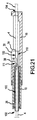
図1は、カテーテル5の可撓性チューブ状本体4のための制御ハンドル2である本発明の一実施形態の等角図である。本明細書を通して、用語カテーテルおよび可撓性の細長い部材は、限定はされないが、カテーテル、シース、および同様の医療機器を含むことを意味する。図1に示すように、一実施形態では、ハンドル2の遠位端部はカテーテル本体4に接続され、かつハンドル2の近位端部はチューブ6に接続され、このチューブは電線を含み、かつ電気コネクタ8まで延在する。ハンドル2は、調整ノブ10およびハンドルグリップ12を含む。本明細書から明らかになるように、本発明のハンドル2は小型であり、かつ使用者が、ハンドルグリップ12に対して調整ノブ10をハンドル2の長手方向軸の周りで一方向または他方向に旋回させることによってカテーテル本体の遠位端部14を双方向に操作できる点で、好都合である。さらに、一実施形態では、ハンドル2は、ハンドル2の近位端部からカテーテル本体4の遠位端部14まで途切れずに延びるルーメンを有する。このルーメンを使用して、ガイドワイヤを挿入するために造影剤を注入できる。
FIG. 1 is an isometric view of an embodiment of the present invention that is a
ハンドル2のより詳細な説明のために、以下、図2および図3を参照する。図2は、様々な構成部品を示すために分解されたハンドル2の等角図である。図3は、図1の切断線AAに沿って取ったハンドル2の縦断面図である。
For a more detailed description of the
図2および図3に示すように、調整ノブ10は、ハンドルグリップ12内に収容されている取り付けシャフト(すなわち、スライドベースまたはベース部分)16に旋回可能に取り付けられる。ノブ10を取り付けシャフト16に旋回可能に取り付けるために、ダウエルピン18がシャフト16の遠位端部にあるピンホール20に差し込まれ、かつノブ10のハブ部分23にある溝22とかみ合う。ノブ10のハブ部分23とシャフト16の遠位端部との間にはシリコーンのoリング24が存在する。
As shown in FIGS. 2 and 3, the
図2および図3に示すように、ワイヤガイド26は調整ノブ10内に位置決めされ、かつ止め輪28によって適所に保持される。右スライドまたは部材30および左スライドまたは部材32が、取り付けシャフト16にあるスロット(すなわち、スライド区画)34内に摺動的に位置決めされる。カテーテル本体−止めナット36を使用して、カテーテル本体4をワイヤガイド26の遠位端部に固定する。
As shown in FIGS. 2 and 3, the
図3に示すように、一対の偏向ワイヤ38が、本体4の遠位端部14から、本体4、ワイヤガイド26、および2つのスライド30と32との間にある通路40を通って、スライド30、32の近位部分に近い点まで延在する。その後、各ワイヤ38は、止めねじ42を介して個々のスライド30、32に固着される。
As shown in FIG. 3, a pair of
スライド30、32およびそれらの偏向ワイヤ38との関係のより詳細な説明のために、ここで、右および左スライド30、32に取り付けられた偏向ワイヤ38a、38bの等角図である図4を参照する。図4に示すように、互いに鏡像関係にあるスライド30、32は、各々、長方形の箱のような近位部分44と、半円筒状の遠位部分46とを有する。各近位部分44は、全体的に平面的な外側側壁および底壁を有する。これらの平面は、スロット34の全体的に平面的な側面および底部に対して摺動的に変位し、これら側面および底部は、スライド30、32のためのスラスト面の機能を果たす。
For a more detailed description of the
各半円筒状の遠位部分46はその長手方向軸に沿ってくり抜かれて通路40を形成し、スライド30、32が組み立て済みのハンドル2にあるときには、その通路を通って、偏向ワイヤ38a、38bおよび図3に示すようにワイヤガイド26の細い近位部分が延在する。各スライド30、32は、平面的な摺動面48を有し、これは、対向するスライド30、32の平面的な摺動面48に摺動的に当接するように意図されて作られている。それゆえ、図2に示すように、スライド30、32の平面的な摺動面48が互いに当接し、かつ各スライド30、32の近位端部が互いに同一平面にある場合、各スライド30、32の半円筒状の遠位部分46が組み合わさって、チャネルまたは通路40が貫通した状態の完全な円筒を形成する。
Each semi-cylindrical
図4に示すように、一実施形態では、各偏向ワイヤ38a、38bの近位端部はループ50を形成し、そこに止めねじ42を通して、ワイヤ38a、38bをそれぞれのスライド30、32の近位部分に固定する。例示的なスライド30の側面図である図5に示すように、一実施形態では、各偏向ワイヤ38の近位端部は、結び目52を形成する。ワイヤ38は、中空の張力調整ねじ54を貫通し、かつ結び目52は、ねじ54の頭55に当接し、それにより、ワイヤ38がねじ54を通して引き戻されないようにする。一実施形態では、ねじの長手方向軸およびスライド30、32の長手方向軸は、全体的に平行になっている。各張力調整ねじ54は、そのそれぞれのスライド30、32の近位端部にねじ式に収容されている。ワイヤ38の張力は、ワイヤの張力調整ねじ54を緩める方向に回すことによって増し得る。反対に、ワイヤ38の張力は、ワイヤの張力調整ねじ54を締め付ける方向に回すことによって、低下し得る。
As shown in FIG. 4, in one embodiment, the proximal end of each
図4から理解できるように、ワイヤ38a、38bが張力を伝えることのみを意図した一実施形態では、スライド30、32が遠位に変位するとき、ワイヤ38a、38bは、各スライド30、32の近位部分44に規定された開放領域45内で偏向または湾曲し得る。同様に、図5から理解できるように、ワイヤ38が張力を伝えることのみを意図した別の実施形態では、スライド30、32が遠位に変位するとき、ワイヤ38はねじ54に関して近位に摺動し得る。
As can be seen from FIG. 4, in one embodiment where the
図4に示すように、一実施形態では、右スライド30の半円筒状の遠位部分46の外周には、右ねじ56がつけられており、左スライド32の半円筒状の遠位部分46の外周には、左ねじ58がつけられている。一実施形態では、右スライド30の半円筒状の遠位部分46の外周には左ねじがつけられており、および左スライド32の半円筒状の遠位部分46の外周には右ねじがつけられている。
As shown in FIG. 4, in one embodiment, the outer periphery of the semi-cylindrical
スライドのねじ56、58の、ハンドル2の残りの部分に対する関係をよりよく理解するために、ここで、図1の切断線AAに沿って取った調整ノブ10の縦断面図である図6を参照する。図6に示すように、シリンダー状孔またはシャフト60が、ノブ10の長手方向軸に沿ってノブを貫通している。ノブ10のハブ部分23において、シャフト60の内周面は右ねじ62および左ねじ64の双方を有する。ノブ10のこれらの雌ねじ62、64は、スライド30、32の対応する雄ねじ56、58とかみ合う。より具体的には、ノブ10の右雌ねじ62が右スライド30の右雄ねじ56とかみ合い、かつノブ10の左雌ねじ64が左スライド32の左雄ねじ58とかみ合う。
To better understand the relationship of the slide screws 56, 58 to the rest of the
それゆえ、図2、図3、図4および図6から理解できるように、一実施形態では、ノブ10がハンドル2の長手方向軸に対して時計回りに回転すると、右の雌ねじおよび雄ねじ62、56が係合し、かつ左の雌ねじおよび雄ねじ64、58が係合し、それにより、ハンドル10にあるスロット34内で長手方向に、右および左スライド30、32を同時に反対方向に変位させる。具体的には、ノブ10およびスライド30、32にねじが配置されているために、ノブ10がハンドル2のハンドルグリップ12に対して時計回りに回転すると、右スライド30はスロット34内で遠位に動き、かつ左スライド32はスロット34内で近位に動く。反対に、ノブ10がハンドル2のハンドルグリップ12に対して反時計回りに回転すると、右スライド30はスロット34内で近位に動き、かつ左スライド32はスロット34内で遠位に動く。
Therefore, as can be seen from FIGS. 2, 3, 4 and 6, in one embodiment, when the
図4および図6から理解できるように、右スライド30を遠位にしかつ左スライド32を近位にするようにノブ10を回転させると、右スライド30に接続された偏向ワイヤ38aが圧縮され、かつ左スライド32に接続された偏向ワイヤ38bに張力がかけられる。これにより、カテーテル本体4の遠位端部14を第1の方向に偏向させる。反対に、右スライド30を近位にして、左スライド32を遠位にするようにノブ10を回転させると、右スライド30に接続された偏向ワイヤ38aに張力がかけられ、および左スライド32に接続された偏向ワイヤ38bは圧縮される。これにより、カテーテル本体4の遠位端部14を、第1の方向と反対の第2の方向に偏向させる。
As can be seen from FIGS. 4 and 6, when the
上述のような本発明の制御ハンドル2にはいくつかの利点がある。第1に、ハンドル2は小型であり、かつ片手で操作し得ることである。第2に、ねじ式スライド30、32およびノブ10は、医師が、カテーテル本体4の遠位端部14の湾曲の制御式の精密な調整を行うことができるようにする。第3に、カテーテル本体4の遠位端部14を湾曲させるようにノブ10が回転したら、ねじ56、58、62、64は相互作用して、医師の側でなんの行為も行う必要なく、湾曲を維持する。第4に、スライド30、32は単にハンドル2の長手方向軸に沿って遠位におよび近位に変位するため、それらは、一部の従来技術のハンドルにおけるワイヤ変位メカニズムと比較して、ワイヤ38を永久的に変形させる可能性が低い。第5に、一部の従来技術のハンドルと比較して、ねじ56、58、62、64は、偏向ワイヤ移動量を多くし、かつ医師の方の作動させる努力を減らすため、機械的に好都合である。
The control handle 2 of the present invention as described above has several advantages. First, the
図2〜6は、スライド30、32が雄ねじ56、58を有し、かつノブ10が雌ねじ62、64を有する実施形態を示すが、別の実施形態では、ねじの配置は逆である。そのような一実施形態の説明のために、図33〜35を参照する。図33は、図1の切断線AAに沿って取ったハンドル2の縦断面図である。図34は、図33に示す実施形態で用いられる例示的なスライドの側面図である。図35は、図1の切断線AAに沿って取った調整ノブの縦断面図である。
2-6 show an embodiment in which the
図33〜35に示した実施形態と、図3、図5および図6に示した実施形態との比較は、2つの実施形態が、図33〜35に関して以下説明することを除いて、全体的に同じであることを明らかにする。図33〜35で用いられる参照符号は、図3、図5および図6の同じ参照符号で識別されるものと同じまたは同様の特徴に関連する。 A comparison of the embodiment shown in FIGS. 33-35 with the embodiment shown in FIGS. 3, 5, and 6 is generally the same except that the two embodiments are described below with respect to FIGS. To be the same. The reference numerals used in FIGS. 33-35 relate to the same or similar features as identified by the same reference numerals in FIGS. 3, 5 and 6.
図33に示すように、調整ノブ10は、ハンドルグリップ12内に収容されている取り付けシャフト(すなわち、スライドベースまたはベース部分)16に旋回可能に取り付けられる。ワイヤガイド26は調整ノブ10内に位置決めされる。図2に示す実施形態のように、図33に示す実施形態は、取り付けシャフト16のスロット(すなわち、スライド区画)34内に摺動的に位置決めされる右スライドまたは部材30と左スライドまたは部材32とを含む。
As shown in FIG. 33, the
図34から理解できるように、互いに鏡像関係にあるスライド30、32は、各々、長方形の箱のような近位部分44と、矩形または半円筒状とし得る遠位部分46とを有する。各近位部分44は、全体的に平面的な外側側壁および底壁を有する。これらの平面は、スロット34の全体的に平面的な側面および底面に対して摺動的に変位し、これらは、スライド30、32のスラスト面としての機能を果たす。
As can be seen from FIG. 34, the
各遠位部分46は、シリンダー状通路40の半分を形成するようにくり抜かれており、このシリンダー状通路は、スライド30、32が互いに並んで当接すると生じる。それゆえ、各スライド30、32の各遠位部分46は内周面を含み、この内周面は、他方のスライド30、32の内周面と組み合わせられると、シリンダー状通路40を規定する。
Each
図34に示すように、一実施形態では、右スライド30の内周面には、右ねじ56がつけられている。同様に、図34から理解できるように、左スライド32の内周面には左ねじ58がつけられている。それゆえ、各スライド30、32の遠位部分46は雌ねじを備える。別の実施形態では、右スライド30の内周面には左ねじ58がつけられている。同様に、左スライド32の内周面には右ねじ56がつけられている。
As shown in FIG. 34, in one embodiment, a
図35に示すように、ノブ10は、内側ハブ23bを取り囲む外側ハブ23aを含む。内側ハブ23bと外側ハブ23aとの間に、それらによって規定された空間65が存在する。空間65は、各スライド30、32の遠位端部46を収容するように適合されている。内側ハブ23bの外周面は、右ねじ62および左ねじ64の双方を有する。ノブ10のこれらの雄ねじ62、64は、スライド30、32の対応する雌ねじ56、58とかみ合う。より具体的には、ノブ10の右雄ねじ62は右スライド30の右雌ねじ56とかみ合い、およびノブ10の左雄ねじ64は、左スライド32の左雌ねじ58とかみ合う。
As shown in FIG. 35, the
図33から理解できるように、一実施形態では、ノブ10がハンドル2の長手方向軸に対して時計回りに回転すると、右の雌ねじおよび雄ねじ56、62が係合し、かつ左の雌ねじおよび雄ねじ58、64が係合し、それにより、右および左スライド30、32を、ハンドル10にあるスロット34内で長手方向に、同時に反対方向に変位させる。具体的には、ノブ10およびスライド30、32のねじ配置に起因して、ノブ10がハンドル2のハンドルグリップ12に対して時計回りに回転すると、右スライド30はスロット34内で遠位に動き、および左スライド32はスロット34内で近位に動く。反対に、ノブ10がハンドル2のハンドルグリップ12に対して反時計回りに回転すると、右スライド30はスロット34内で近位に動き、かつ左スライド32はスロット34内で遠位に動く。
As can be seen from FIG. 33, in one embodiment, when the
図33から理解できるように、右スライド30を遠位にし、かつ左スライド32を近位にするようにノブ10を回転させると、右スライド30に接続された偏向ワイヤ38が圧縮され、および左スライド32に接続された偏向ワイヤ38に張力がかけられる。これにより、カテーテル本体4の遠位端部14を第1の方向に偏向させる。反対に、右スライド30を近位にし、かつ左スライド32を遠位にするようにノブ10を回転させると、右スライド30に接続された偏向ワイヤ38には張力がかけられ、および左スライド32に接続された偏向ワイヤ38は圧縮される。これにより、カテーテル本体4の遠位端部14を、第1の方向とは反対の第2の方向に偏向させる。
As can be seen from FIG. 33, when the
本発明のハンドル2の別の実施形態の詳細な説明のために、ここで、図7、図8および図9を参照する。図7は、ハンドル2の平面図である。図8は、ハンドル2の側面図である。図9は、ハンドル2の遠位端部の等角図である。
For a detailed description of another embodiment of the
図7〜9に示すように、ハンドル2は、その遠位端部に調整ノブ10を、およびその近位端部にハンドルグリップ12を有する。図7〜9から理解できるように、一実施形態では、ノブ10は全体的に円形断面を有し、およびハンドルグリップ12は、全体的に卵形断面を有する。一実施形態では、ノブ10およびハンドルグリップ12の双方とも、全体的に円形断面を有する。ハンドルグリップ12が卵形断面であることは、これにより医師にカテーテルの回転位置を触覚で示すため、好都合である。
As shown in FIGS. 7-9, the
ハンドル2の構成要素のより詳細な説明について、ここで、図9の切断線BBに沿って取ったハンドル2の縦断面の平面図である図10を参照する。図10に示すように、ハンドルグリップ12とノブ10にある溝との間にはoリング24が配置される。ノブ10は、回転する止め輪60を介してハンドルグリップ12に旋回式に固着され、この止め輪は、ノブおよびハンドルグリップ12の双方の溝にある。
For a more detailed description of the components of the
図10に示すように、カテーテル本体−止めナット36は、ノブ10の軸方向中心に沿って延在するワイヤガイド26の遠位端部にねじ式に固着される。図10に示すように、および図9の切断線BBに沿って取ったノブ10の縦断面の平面図である図11により明確に示すように、円筒状孔またはシャフト60は、ノブ10の長手方向軸に沿ってノブを貫通する。シャフト60の内周面は、ノブ10のハブ部分23からノブ10の遠位端部の方へ延在する右ねじ62および左ねじ64の双方を有する。図11に示すように、一実施形態では、ノブ10は、単一の一体部片である。
As shown in FIG. 10, the catheter body-
図10に示すように、右スライド30および左スライド32は、ハンドル2内で長手方向にかつワイヤガイド26の近位端部の辺りで変位可能である。ワイヤガイド26の辺りで変位されたスライド30、32の右等角図およびワイヤガイド26の辺りで変位されたスライド30、32の左等角図をそれぞれ示す図12および図13に示すように、各スライド30、32は、対向するスライド30、32の摺動面48に対して当接しかつ摺動的に変位する平面的な摺動面48を有する。また、各スライド30、32はチャネル40を有し、このチャネルは、対向するスライド30、32のチャネル40と組み合わさって通路40を形成し、スライド30、32がワイヤガイド26の辺りで変位するにつれ、この通路をワイヤガイド26の近位端部が通る。図10に示すように、チャネル40によって形成された通路40はまた、偏向ワイヤ38a、38b(図10に破線で示す)が、スライド30、32の近位部分から、ワイヤガイド26を通って、およびカテーテル本体4の遠位端部14に向かって移動する経路を提供する。
As shown in FIG. 10, the
図12および図13に示すように、各スライド30、32は、半円筒状の遠位部分46と、それよりも短くかつ太い半円筒状近位部分47とを有する。右スライド30は、その遠位部分46に右巻きのねじ56を有する。同様に、左スライド32は、その遠位部分46に左巻きのねじ58を有する。それゆえ、図10から理解できるように、ノブ10をハンドルグリップ12に対して時計回り方向に回転させると、ノブ10内の右巻きのねじ62が右スライド30の右巻きのねじ56と係合し、およびノブ10内の左巻きのねじ64が左スライド32の左巻きのねじ58と係合する。その結果、右スライド30は、ハンドル2内で遠位に変位され、および左スライド32は、ハンドル2内で近位に変位される。それゆえ、右スライド30に取り付けられた偏向ワイヤ38aが押され(すなわち、圧縮力を受ける)、かつ左スライド32に取り付けられた偏向ワイヤ38bが引っ張られる(すなわち、張力を受ける)。反対に、ノブが反時計回りに回転される場合、スライド30、32および偏向ワイヤ38a、38bの反対方向の変位が生じる。
As shown in FIGS. 12 and 13, each
図10に示すように、各偏向ワイヤ38a、38bは、止めねじ42を介してそのそれぞれのスライド30、32の近位部分47に取り付けられる。図12および図13により明確に示される止めねじは、近位部分47にねじ式に装着される。
As shown in FIG. 10, each
図12および図13に示すように、スライド30、32の各半円筒状の近位部分47は、それらそれぞれの平面的な摺動面48に隣接する平面的な上部および下部ノッチ64を有する。これらのノッチ64の機能は、図14および図15を参照することにより理解し得る。
As shown in FIGS. 12 and 13, each semi-cylindrical
図14は、図7の切断線CCに沿って取ったハンドルグリップ12の縦断面図である。図15は、図8の切断線DDに沿って取ったハンドルグリップ12の横断面図である。図14および図15に示すように、ハンドルグリップ12は、シリンダー状の内部空洞66を有する1つの一体部片であり、図10に示すように、その空洞内でスライド30、32の近位部分47が変位し得る。
14 is a longitudinal sectional view of the
図14および図15に示すように、上部および下部リブ68が、シリンダー状の内部空洞66を形成する壁から延出する。リブ68は、シリンダー状の空洞の長さのかなりの部分に沿って長手方向に延びる。図12〜図15から理解できるように、スライド30、32がシリンダー状の空洞66内で変位するにつれ、スライド30、32の近位部分47にある平面的な上部ノッチ64は、上部リブ68と接触しかつそれに沿って変位する。同様に、スライド30、32がシリンダー状の空洞66内で変位するにつれ、スライド30、32の近位部分47にある平面的な下部ノッチ64は、下部リブ68と接触しかつそれに沿って変位する。それゆえ、リブ68は、スライド30、32のスラスト面の機能を果たす。
As shown in FIGS. 14 and 15, upper and
図7〜15に示すハンドル2の別の実施形態の詳細な説明については、ここで、図16を参照する。図16は、カテーテル5用の制御ハンドル2の遠位端部の等角図であり、ハンドル2およびカテーテル本体4は、貫通ルーメン70を有する。図16に示すように、一実施形態では、ルーメン70と、電気コネクタ8まで延在する電線チューブ6とが、張力緩和部71を通って、ハンドルグリップ12の近位端部まで通過する。一実施形態では、ルーメン70は、ストップコック72を備えるその近位端部で終端する。一実施形態では、ストップコック72は止血封止部74を有し、止血封止部を用いて、ガイドワイヤを挿入することができる。図16に示すような可撓性の長いルーメン70は、注射器から造影剤を注入する間、動きを分離するが、一実施形態では、ルーメン70はハンドルグリップ12から延出しない。その代わり、ルーメンがハンドルグリップ12の近位端部から出る個所において、単にルーメン70にストップコック72またはルアーフィッティングが取り付けられる。
Reference is now made to FIG. 16 for a detailed description of another embodiment of the
ルーメン70の経路をよりよく理解するために、ここで図17、図18および図19を参照する。図17は、スライド30、32、ワイヤガイド26、ワイヤチューブ6、およびルーメン70の等角図であり、ルーメン70がハンドル2を通って辿る経路を示す。図18は、図17の矢印Aの方向から見たスライド30、32の近位端部表面の立面図であり、およびルーメン70およびワイヤチューブ6が、スライド30、32のチャネル40によって形成された通路40で辿る経路を示す。図19は、ハンドル2の遠位端部にあるカテーテル本体−止めナット36から出るルーメン70、偏向ワイヤ38a、38b、およびワイヤチューブ6の電線76の等角図である。
In order to better understand the path of the
図17および図18に示すように、ルーメン70およびワイヤチューブ6は、それらそれぞれの緩和部71を通って、各スライド30、32のチャネル40によって形成された通路40まで通過する。一実施形態では、ワイヤチューブ6およびルーメン70が通路40に入った後直ぐに、ワイヤチューブ6の電線76はワイヤチューブ6から出て、図19に示すようにルーメン70の外周の周りに分配される。
As shown in FIGS. 17 and 18, the
図17に示すように、別の実施形態では、ワイヤチューブ6およびルーメン70が通路40に入った後、ワイヤチューブ6およびルーメン70はそれらの経路を、隣り合った配置で、スライド30、32に形成された通路40の残りの部分を通って、ワイヤガイド26の長手方向軸に沿って延びる内部通路まで通過させることによって、カテーテル本体4の遠位端部14まで辿り続ける。ワイヤガイド26の端部近くで、電線76はワイヤチューブ6から出る。その後、電線76、ルーメン70および偏向ワイヤ38a、38bは、図19に示すように、ハンドルのカテーテル本体−止めナット36から出ることによってカテーテルに入る。
As shown in FIG. 17, in another embodiment, after the
ハンドル2の別の実施形態の詳細な説明については、ここで、様々な構成部品を示すために分解されたハンドル2の等角図である図20を参照する。図20から理解できるように、図20に示すハンドル2の特徴は、図20に示すハンドル2を、比較的大きくて全体的に均一の直径の経路がハンドル2の全長に(すなわち、ワイヤガイド26の遠位開口部102から、スライド30、32に規定された通路40を通って、およびシャフト16の近位端部にある出口孔104を通って)延在するように構成していることを除いて、図2に示すハンドルの特徴と同様である。
For a detailed description of another embodiment of the
図20に示すような、比較的大きくて全体的に均一の直径の経路がハンドル2の長さを通過できるようにするハンドル2の構成は、図21により明確に示す。図21は、図20の切断線ZZに沿って取った縦断面図である。図21に示すように、一実施形態では、ワイヤガイド26を通る通路とスライド30、32を通る通路40とを含む経路100は、カテーテル本体4自体が経路100を通りかつ出口孔104においてシャフト16の近位端部に接続され得るように、十分に大きい。それゆえ、一実施形態では、カテーテル本体4が調整ノブ10と共に回転しないようにするために、カテーテル本体4を出口孔104においてシャフト16に固着させる。一実施形態では、カテーテル本体4は、本体4が遠位開口部102においてまたはその付近でワイヤガイド26に固着されていることを除いて、図21に示すようにハンドル4の全長に延びる。別の実施形態では、カテーテル本体4は、遠位開口部102においてまたはその付近でワイヤガイド26、および出口孔104においてシャフト16の双方に固着される。
The configuration of the
図21から理解できるように、および各スライドの通路40の部分および平面的な摺動面48を示すような向きにされたスライド30、32の等角図である図22により明白に示すように、通路40の直径は、ワイヤガイド26の外径にわたって変位できるように十分に大きい。図21および図22に示すように、カテーテル本体の通路110は、各スライド30、32の近位部分44を貫通し、それにより、カテーテル本体4の外表面上でスライド30、32を前後に変位させることができる。
As can be seen from FIG. 21, and more clearly as shown in FIG. 22, which is an isometric view of
図21に示すように、一実施形態では、カテーテル本体4はその壁に、ワイヤ38が本体4から出てスライド30、32につながることができるようにする開口部111を有する。一実施形態では、ワイヤ38は、前述の通り張力調整ねじ54を介してスライド30、32につながる。
As shown in FIG. 21, in one embodiment, the catheter body 4 has an
スライド30、32、ワイヤガイド26およびシャフト16の構成に起因して、カテーテル本体4は、ハンドル2の全長に途切れずに延び得る。その結果、電線76(図19参照)およびルーメン70は、本体4によってハンドル2の全長に送られる。
Due to the configuration of the
本発明のハンドル2の別の実施形態の詳細な説明については、ここで、図23および図24を参照する。図23は、様々な構成部品を示すために分解されたハンドル2の等角図である。図24は、図23の切断線YYに沿って取ったハンドル2の縦断面図である。一般的に言えば、図23および図24に示すハンドル2の特徴は、2つの実施形態が異なるスライダ構成を用いることを除いて、図20に示すハンドルの特徴と同様である。例えば、図1〜22に示す実施形態は、並列なスライドまたは部材30、32を用いる(すなわち、スライド30、32はハンドル2内で並列にまたは隣り合った配置で存在する)。図23および図24および以下の図面から理解されるように、図23および図24に示すハンドル2の実施形態において、スライドまたは部材150、152は、調整ノブ10内に直列の配置で存在する(すなわち、スライド150、152は互いに並列しても隣り合ってもいないが、ハンドル2の長手方向軸に沿って端と端が向き合っている)。
For a detailed description of another embodiment of the
図23および図24に示すように、調整ノブ10は、取り付けシャフト16の遠位端部(すなわち、ベース部分)に旋回式に結合されている。ワイヤガイド26は、調整ノブ10および取り付けシャフト16の中心を通って延在する。カテーテル本体4は、ワイヤガイド26の遠位端部に結合され、および一実施形態では、ワイヤガイド26を通って、取り付けシャフト16の近位端部から出て延在する。
As shown in FIGS. 23 and 24, the
図23および図24に示すように、調整ノブ10の遠位部分に遠位スライド150が配置され、および調整ノブ10の近位部分(すなわち、ハブ部分23)に近位スライド152が配置される。図24に示すように、各スライド150、152の外表面はねじ154を有し、このねじは、調整ノブ10の内部表面にあるねじ156とかみ合う。
As shown in FIGS. 23 and 24, a
図24に示すように、各偏向ワイヤ38a、38bは、ワイヤガイド26の内部に沿って伸び、ワイヤガイド26の側壁にある孔157においてワイヤガイド26から出る。その後、各偏向ワイヤ38a、38bはスライド150、152までそれぞれ延在し、そこに偏向ワイヤ38a、38bは取り付けられる。一実施形態では、スライド150、152につなぐために、偏向ワイヤ38a、38bは、スライド150、152の通路159をそれぞれ通過し、およびこの詳細な説明で前述したように、結び目52を介して中空の張力調整ねじ54にそれぞれ結合する。
As shown in FIG. 24, each
ねじ154、156の向きをよりよく理解するために、ここで、図25および図26を参照する。図25は、調整ノブ10を単独で示すことを除いて、図24に示すものと同じ調整ノブ10の縦断面図である。図26は、スライド150、152の側面図である。
For a better understanding of the orientation of the
図25および図26に示すように、一実施形態では、遠位スライド150は、調整ノブ10の遠位部分にある右ねじ156と係合する右ねじ154を有し、および近位スライド152は、調整ノブ10の近位部分にある左ねじ156と係合する左ねじ154を有する。それゆえ、図23〜26から理解できるように、調整ノブ10を取り付けシャフト16に対して第1の方向にハンドル2の長手方向軸の周りで回転させると、スライド150、152は、ワイヤガイド26に沿って互いに近づき、それにより、第1のワイヤ38に張力をかけ、かつ第2のワイヤ38を圧縮させる。その結果、カテーテル本体4の遠位端部14が第1の方向に偏向する。同様に、調整ノブ10を、第1の方向とは反対の第2の方向に回転させると、スライド150、152はワイヤガイド26に沿って互いに遠ざかり、それにより、第1のワイヤ38を圧縮させ、かつ第2のワイヤ38に張力をかける。その結果、カテーテル本体4の遠位端部14は、第1の方向とほぼ反対の第2の方向に偏向する。
As shown in FIGS. 25 and 26, in one embodiment, the
一実施形態では、調整ノブ10の回転時にスライド150、152が単にワイヤガイド26の周りで回転しないようにするために、スライド150、152およびワイヤガイド26を、スライド150、152はワイヤガイド26に沿って変位するがその周りで回転しないように、構成する。例えば、図24の切断線XXに沿って取ったようなハンドル2の横断面図である図27Aに示すように、ワイヤガイド26は、スライド150、152の長さ方向に延びる正方形の孔162とかみ合う正方形断面を有する。正方形の孔162とワイヤガイド26の正方形断面との相互作用によって、スライド150、152がワイヤガイド26の周りで回転しないようにするが、依然としてスライド150、152はワイヤガイド26の長さに沿って変位できるようにする。
In one embodiment, to prevent the
別の実施形態では、図27Aに示すものと同じ横断面図である図27Bに示すように、各スライド150、152は、円形断面を備える孔162を有する。各孔162は、そのそれぞれのスライド150、152の長さ方向に延び、かつ鍵160を含み、その鍵は、孔160の内部周囲面から孔162まで延在する。鍵160は、図28に示すようにワイヤガイド26の長さに沿って延びる溝またはスロット158に係合する。図28は、ワイヤガイド26の一実施形態の側面図である。鍵160とスロット158との相互作用によって、スライド150、152がワイヤガイド26の周りで回転しないようにするが、依然として、スライド150、152がワイヤガイド26の長さに沿って変位できるようにする。
In another embodiment, as shown in FIG. 27B, which is the same cross-sectional view as shown in FIG. 27A, each
図27Aおよび図27Bに示すように、中空シャフト165は、ワイヤガイド26にわたって延在する。これにより、ルーメンを備えるカテーテル本体4は、図24に示すようにハンドル2を通って完全に延在できる。
As shown in FIGS. 27A and 27B, the
図23に示す実施形態のものと同様のハンドル2の別の実施形態の詳細な説明については、ここで、図29および図30を参照する。図29は、図23の切断線YYに沿って取ったかのようなハンドル2の縦断面図である。図30は、図23の切断線VVに沿って取ったかのようなハンドル2の縦断面の平面図であり、および切断線VVは、図23の切断線YYによって形成された平面に対して垂直な平面をなす。
Reference is now made to FIGS. 29 and 30 for a detailed description of another embodiment of the
図29および図30に示すように、ハンドル2は、取り付けシャフト16の遠位端部(すなわち、ベース部分)に旋回式に結合された調整ノブ10を含む。一実施形態では、調整ノブ10は、近位端部170と、遠位端部172と、近位端部170に接続されかつ調整ノブ10の長手方向軸に沿って遠位に延在するねじシャフト173とを含む。ねじシャフト173は、遠位端部174と、近位端部176と、シャフト173の遠位部分に沿った一連の右ねじ178と、シャフト173の近位部分に沿った一連の左ねじ180とを含む。
As shown in FIGS. 29 and 30, the
図29および図30に示すように、遠位スライド150が調整ノブ10の遠位部分に配置され、および近位スライド152が調整ノブ10の近位部分(すなわち、ハブ部分23)に配置される。各スライドは孔155を有し、そこをねじシャフト173が通る。遠位スライド150用の孔155の内周面は右ねじを有し、これは、シャフト173の遠位部分にある右ねじ178とかみ合う。同様に、近位スライド152用の孔155の内周面は左ねじを有し、これは、シャフト173の近位部分にある左ねじ180とかみ合う。別の実施形態では、左ねじおよび右ねじの位置は逆である。
29 and 30, the
ワイヤガイド26の一実施形態の等角図である図29、図30および図31から理解できるように、中空中心シャフト182が、ワイヤガイド26の遠位端部から、調整ノブ10のねじシャフト173を通って、ベースシャフト16の近位端部まで延在する。それゆえ、一実施形態では、図29および図30に示すように、カテーテル本体4は、ワイヤガイドの中空中心シャフト182のルーメン165を通って送られて、ハンドル2の近位端部から出てもよい。
As can be seen from FIGS. 29, 30 and 31, which are isometric views of one embodiment of the
図29に示すように、各偏向ワイヤ38a、38bは、ワイヤガイド26の内部に沿って伸び、ワイヤガイド26の側壁にある孔157においてワイヤガイド26から出る。次いで、各偏向ワイヤ38a、38bはスライド150、152までそれぞれ延在し、そこに偏向ワイヤ38a、38bを取り付ける。一実施形態では、スライド150、152に取り付けるために、偏向ワイヤ38a、38bは、スライド150、152にある通路159を通り、かつこの詳細な説明で前述したように結び目52によって中空の張力調整ねじ54に結合される。
As shown in FIG. 29, each
一実施形態では、図29に示すように、近位スライド152に至る偏向ワイヤ38bは、遠位スライド150にある第2の通路161を通る。第2の通路161は、遠位スライド150が遠位におよび近位に変位する際、通路161がワイヤ38bに沿って容易に変位し得るような十分なクリアランスを有する。第2の通路161は、ワイヤ38bを強化するガイドの機能を果たし、かつワイヤ38bが圧縮されるときに湾曲する可能性を低下させるのを助ける。
In one embodiment, as shown in FIG. 29, the
図29および図30から理解できるように、調整ノブ10を取り付けシャフト16に対して第1の方向にハンドル2の長手方向軸の周りで回転させると、スライド150、152はねじシャフト173に沿って互いに近づき、それにより、第1のワイヤ38aには張力がかけられ、および第2のワイヤ38bは圧縮されるようにする。その結果、カテーテル本体4の遠位端部14は第1の方向に偏向する。同様に、調整ノブ10を、第1の方向とは反対である第2の方向に回転させると、スライド150、152はねじシャフト173に沿って互いに遠ざかり、それにより、第1のワイヤ38aを圧縮させ、かつ第2のワイヤ38bには張力がかけられる。その結果、カテーテル本体4の遠位端部14は、第1の方向とはほぼ反対の第2の方向に偏向される。
As can be seen from FIGS. 29 and 30, when the
一実施形態では、調整ノブ10の回転時に、スライド150、152が、単に、調整ノブ10内のねじシャフト173と共に回転しないようにするために、スライド150、152およびワイヤガイド26を、スライド150、152がねじシャフト173に沿って変位するが調整ノブ10内で回転しないように、構成する。例えば、図31および図32(図29の切断線WWに沿って取ったハンドル2の横断面図である)に示すように、ワイヤガイド26は右および左半円部分190を有し、これら半円部分は互いに対向し、かつワイヤガイド26の中空中心シャフト182の長さに沿って延在する。図32に示すように、半円部分190の全体的に平面的な対向面192は、スライド150、152の全体的に平面的な側面194に当接する。この接触によって、ノブ10の回転時に調整ノブ10内でスライド150、152が回転しないようにするが、依然としてねじシャフト173の長さに沿ったスライド150、152の変位は可能にする。
In one embodiment, to prevent the
患者200に対する外科的処置に用いられる本発明の制御ハンドル2の概略図である図36から理解できるように、カテーテル本体4の遠位端部14を患者200に挿入する(例えば、患者200の体内腔202を介して静脈内に、経皮的に、または患者の体に入れる他の手段を介して)。カテーテル本体4の遠位端部14は、患者200内の選択された個所に位置決めされるまで進められる(例えば、患者の心臓206の腔204または患者の体腔を備える他の器官内までなど)。次いで、カテーテル本体4の遠位端部は、調整ノブ10をベース部分16の長手方向軸の周りで回転させることによって、偏向される。図1〜35から理解できるように、これにより、ハンドル2内のスライド30、32を、長手方向軸に沿って反対方向に変位させる。各スライド30、32をそのそれぞれの偏向ワイヤ38に結合し、かつ各偏向ワイヤ38はカテーテル本体4を通って延びて遠位端部14に結合されているため、カテーテル本体4の遠位端部14は偏向される。
As can be seen from FIG. 36, which is a schematic view of the control handle 2 of the present invention used in a surgical procedure on a
図37〜49に示すさらに別の実施形態では、多方向性カテーテル制御ハンドル230を使用して、カテーテル本体の遠位端部(または遠位端部分または遠位部分)を様々な向きに操作する。多方向性カテーテル制御ハンドル230は、図1〜36を参照して説明した実施形態と比較して、操作性をさらに高めている。多方向性カテーテル制御ハンドル230は、調整ノブを1つ使用することとは対照的に、第1の調整ノブおよび第2の調整ノブを使用することにより、カテーテル本体の遠位端部の操作性を高めている。 In yet another embodiment shown in FIGS. 37-49, a multidirectional catheter control handle 230 is used to manipulate the distal end (or distal end portion or distal portion) of the catheter body in various orientations. . The multi-directional catheter control handle 230 further enhances operability compared to the embodiment described with reference to FIGS. The multi-directional catheter control handle 230 uses the first adjustment knob and the second adjustment knob as opposed to using one adjustment knob, so that the operability of the distal end of the catheter body is improved. Is increasing.
図37は、ハンドルグリップ232、右/左(R/L)調整ノブ234、前方/後方(A/P)調整ノブ236、および長手方向軸238を有する多方向性カテーテル制御ハンドル230の一実施形態を示す。2つの調整ノブ234を備える場合、多方向性カテーテル制御ハンドル230は、カテーテル本体の遠位端部の向きを同様に制御する少なくとも2対の偏向ワイヤを制御し得る。
FIG. 37 illustrates one embodiment of a multi-directional catheter control handle 230 having a
明瞭にするために少なくとも1つの構成要素を除去して示した図38は、4つの偏向ワイヤ240a〜240dの向きを、電線76に隣接するルーメン70の周りで決定する方法を示す。4つの偏向ワイヤ240a〜240dは、調整ノブとカテーテル本体の遠位端部とに動作可能に結合され得る。一実施形態では、例えば、R/L調整ノブ234は、偏向ワイヤ240aおよび240bの動きを制御し、かつA/P調整ノブ236は、偏向ワイヤ240cおよび240dの動きを制御し得る。それゆえ、R/L調整ノブ234を回転させることにより、遠位端部を右方向および左方向に偏向させる。同様に、A/P調整ノブ236を回転させることにより、遠位端部を前方および後方に偏向させる。遠位端部の動きを、下記でより詳細に説明する。しかしながら、4つの「基本的な」方向(すなわち、右、左、前方および後方)での偏向に加え、当業者は、調整ノブ234、236の回転を組み合わせるかまたは順次に行うことにより、遠位端部を、偏向ワイヤ240に対しておよび/または可撓性の細長い部材の残りの部分に対して斜角に向けてもよいことを認識する。それゆえ、カテーテルの遠位端部の操作性を高める。
FIG. 38, with at least one component removed for clarity, illustrates how the orientation of the four deflection wires 240 a-240 d is determined around the
この操作性を高めた多方向性カテーテル制御ハンドル230の一実施形態の構成要素を、図39に分解図で示す。これらの構成要素を、3つの非相互排他的な群:R/Lカテーテル偏向およびA/Pカテーテル偏向の双方を達成するのを助ける第1の群の構成要素、主にA/Pカテーテル偏向を達成するのに使用される第2の群の構成要素、および主にR/Lカテーテル偏向を達成するのに使用される第3の群の構成要素に分類できる。これらの群は、単に、多方向性カテーテル制御ハンドル230の説明を容易にするものにすぎず、決して、いずれかの所与の構成要素の機能、目的、利益などを限定するものではない。また、特に使用者がR/L偏向とA/P偏向を統合する場合、これら群の全てからの構成要素を使用して、カテーテル本体の遠位端部を偏向させる。 The components of one embodiment of the multidirectional catheter control handle 230 with enhanced operability are shown in an exploded view in FIG. These components are divided into three non-mutually exclusive groups: a first group of components that help achieve both R / L catheter deflection and A / P catheter deflection, mainly A / P catheter deflection. A second group of components used to achieve, and a third group of components used primarily to achieve R / L catheter deflection. These groups merely facilitate the description of the multi-directional catheter control handle 230 and in no way limit the function, purpose, benefit, etc. of any given component. Also, particularly when the user integrates R / L deflection and A / P deflection, components from all of these groups are used to deflect the distal end of the catheter body.
ハンドルグリップ232は、R/LおよびA/P偏向の双方の最中に有用な、そのような1つの一般的な構成要素である。ハンドルグリップ232を、2つの副部品232a、232bで示し、かつ多方向性カテーテル制御ハンドル230の近位端部に配置する。ハンドルグリップ232を2つの副部品232a、232bから形成することによって、必要に応じて内部部品に迅速にアクセスできるようにする。エンドキャップ250およびクリップ形体252が、取り付けシャフト254の周りにハンドルグリップ副部品232a、232bを保持するのを助け得る。この取り付けシャフトは、ハンドル230のいくつもの構成要素の支持部材の機能を果たす。エンドキャップ250は、副部品232a、232bから延出する全体的な周囲リム256a、256bをそれぞれ固定し得る。クリップ形体252は、副部品232a、232b上にある内部リム258とかみ合って、取り付けシャフト254の周りにハンドルグリップ232をさらに固定するように構成し得る。
Handle
さらに、ノズル様突起260は、R/LおよびA/P偏向の双方の最中に有用とし得る。ノズル様突起260は、突起260から延出するカテーテルの可撓性チューブ状本体に張力緩和をもたらし得る。さらに、ノズル様突起260は、下記で説明するようにワイヤガイド上のねじとかみ合う雌ねじを有し得る。
Further, the nozzle-
図39はまた、カテーテル本体の遠位端部のA/P偏向を可能にする多方向性カテーテル制御ハンドル230の構成要素を示す。特に、ハンドル230は、図4に示すものと似ていてもよい第1のスライド270および第2のスライド272を含み得る。スライド270、272は、互いに鏡像関係にあってもよく、および近位部分274および遠位部分276を含み得る。偏向ワイヤは、第1および第2のスライド270、272の近位部分274に動作可能に結合し得る。例えば、図38の一対の偏向ワイヤ240c、240dは、第1および第2のスライド270、272の近位部分274に動作可能に結合し得る。それゆえ、第1および第2のスライド270、272を移動させることにより、一対の偏向ワイヤ240c、240d、最終的にはカテーテル本体の遠位端部を制御し得る。
FIG. 39 also illustrates the components of the multidirectional catheter control handle 230 that allow A / P deflection of the distal end of the catheter body. In particular, the
偏向ワイヤは、例えば、止めねじまたは半田付けを使用することを含むいくつもの技術によって、近位部分274に動作可能に取り付けられ得る。一部の実施形態では、例えば、第1および第2のスライド270、272の近位部分274は、偏向ワイヤが摺動的に延在し得る孔を有し得る。単一の偏向ワイヤに関して、例えば、近位部分274の1つを越えて近位に突出する偏向ワイヤのセグメントは、近位部分274にある孔を通過できないほどの多量の半田に取り付けられ得る。「中立位置」から近位に摺動するスライドの近位部分274を移動させることにより、下記でさらに説明するように、多量の半田および取り付けられた偏向ワイヤを近位に移動させ得る。しかし、近位部分274が中立位置から遠位に移動されるとき、摺動的に取り付けられた偏向ワイヤおよび多量の半田は、概して静止したままとし得る。これらの実施形態では、対応する調整ノブの回転は、一対の偏向ワイヤの一方のみの張力を一度に変更する。一対の偏向ワイヤの一方の若干の弛みは、R/L調整ノブ234およびA/P調整ノブ236の双方を使用してカテーテルの遠位端部を様々な向きに操作する場合、好都合となり得る。
The deflection wire can be operatively attached to the
さらに、第1のスライド270の遠位部分276は右回りの角ねじを含む一方、第2のスライド272の遠位部分276は左回りの角ねじを含み得る。角ねじを備えるスライド270、272を構成することによって、スライド270、272は、変位後に元の状態に戻らないかまたは少なくともそのような傾向が少ない。角ねじは、自動ロック式特性を有し、これにより、ねじが滑ったりまたは後退したりしにくくなる。図12に示すスライドと同様に、スライド270、272はくり抜かれて、例えば、ルーメンおよび偏向ワイヤ240を含むカテーテルの様々なワイヤのための通路278を形成してもよい。および、さらに、スライド270、272を、移動はするが、それらの近位部分274および取り付けシャフト254の外形に起因して回転しないように、取り付けシャフト254内に位置決めし得る。
Further, the
第1および第2のスライド270、272を移動させるために、雌角ねじ切りを備える調整ノブインサート280が設けられてもよい。調整ノブインサート280は、インサート280のハブ部分282を取り付けシャフト254の遠位開口部284に差し込むことによって、取り付けシャフト254に回転可能に結合されてもよい。ダウエルピン286を角状ピンホール288に差し込んで、ハブ部分282にある溝290を固定する。回転可能に結合されたら、調整ノブインサート280は、長手方向軸238の周りで回転し得るが、取り付けシャフト254の長さに沿った移動は防止される。調整ノブインサート280は右回りおよび左回りの雌ねじを有してもよく、これらねじは、インサート280にあるねじを角ねじとし得ることを除いて、図11に示したものと同様である。それゆえ、第1および第2のスライド270、272の遠位部分274は、調整ノブインサート280内に差し込まれ、インサート280の雌ねじはスライド270、272の雄ねじ、またはその一部と係合し得る。
An
調整ノブインサート280が一方に回転すると、第1のスライド270は、第2のスライド272とは反対の方向に移動する。調整ノブインサート280が他方に回転すると、各スライド270、272はそれぞれ、逆方向に移動し得る。このスライド270、272の前後の移動は、A/P偏向を可能にするカテーテルハンドル230の一態様である。
As the
さらに図39を参照して、多方向性カテーテル制御ハンドル230はまた、調整ノブインサート280内と第1および第2のスライド270、272によって形成された通路278内とに位置決めされたワイヤガイド300を含み得る。調整ノブインサート280の回転時にワイヤガイド300が回転しないようにするために、ワイヤガイド300は、第1および第2のスライド270、272内のスロット304に差し込むことができる突起302を有し得る。第1および第2のスライド270、272は取り付けシャフト254に対して回転しないため、突起302がスロット304内に差し込まれたら、ワイヤガイド300も回転しない。さらに、少なくとも1つのワッシャおよび止め輪306が、ワイヤガイド300の遠位端部(図示せず)を調整ノブインサート280内の適所に保持する。ワイヤガイド300の遠位端部は、ノズル様突起260に配置された雌ねじと係合できるように、ねじが切られていてもよい。さらにまた、A/P調整ノブ236は、調整ノブインサート280の遠位部分310に圧入され得る。A/P調整ノブ236は、調整ノブインサート280自体とは対照的に、ハンドル230の使用者に対してより効果的な接触面を提供し得る。代替的な実施形態では、A/P調整ノブ236を調整ノブインサート280の遠位部分310と一体にして、A/P調整ノブ236を遠位部分310に圧入する必要がないようにしてもよい。いずれの場合にも、雌ねじは、A/P調整ノブ236内に配置されると言える。
Still referring to FIG. 39, the multi-directional catheter control handle 230 also has a
加えて、図39は、カテーテル本体の遠位端部のR/L偏向を可能にする多方向性カテーテル制御ハンドル230の構成要素を示す。特に、右スライド320および左スライド322が設けられ得る。右スライド320は近位タブ324を含んでもよく、この近位タブは、右スライド320の平坦部分328が取り付けシャフト254に対して位置決めされると取り付けシャフト254内のスロット326を通って延在する。位置決めされたら、右スライド320および近位タブ324は、取り付けシャフト254の長さの一部分に沿って移動し得る。右スライド320は、さらに、R/L調整ノブ234の雌ねじ(図示せず)と係合する1組の右角ねじ330を含み得る。第1および第2のスライド270、272の角ねじと同様に、右スライド320の角ねじ330は、ねじが滑ったりまたは後退したりしないようにするかまたは少なくともその可能性を低下させる。
In addition, FIG. 39 shows components of a multidirectional catheter control handle 230 that allows R / L deflection of the distal end of the catheter body. In particular, a
右スライド320と同様に、左スライド322も近位タブ340を含んでもよく、この近位タブは、左スライド322の平坦部分344が取り付けシャフト254に対して位置決めされると取り付けシャフト254のスロット342を通って延在する。位置決めされたら、左スライド322および近位タブ340はまた、取り付けシャフト254に対して近位におよび遠位に移動し得る。右および左スライド320、322双方を取り付けシャフト254に接して位置決めすると、左スライド322の近位タブ340は、右スライド320の近位タブ324の下方に載置され得る。同様に、左スライド322も、R/L調整ノブ234の雌ねじと係合する1組の左角ねじ346を有し得る。それゆえ、R/L調整ノブ234は、右回りおよび左回り雌ねじを有してもよく、これらねじは、R/L調整ノブ234のねじを角ねじとし得ることを除いて、図11に示すねじと同様である。R/L調整ノブ234を長手方向軸238の周りで回転させることにより、右および左スライド320、322をハンドル230の長さに沿って反対方向に移動させ得る。
Similar to the
近位タブ324、340は、例えば図38に示す一対の偏向ワイヤ240a、240bなどの偏向ワイヤの設置点を提供し得る。第1および第2のスライド270、272と同様に、偏向ワイヤは、例えば、止めねじまたは半田付けを使用することを含むいくつもの技術によって近位タブ324、340に取り付けられ得る。それゆえ、R/L調整ノブ234が右および左スライド320、322を反対方向に移動させると、2つの取り付けられた偏向ワイヤの少なくとも一方−A/P調整ノブ236によって制御されるものではない−に加えられる張力が増加または低下される。
本明細書では用語「第1」、「第2」、「右」、「左」、「R/L」、および「A/P」を使用するが、そのような用語は、単にこの詳細な説明の便益を目的としているにすぎないことに留意されたい。それゆえ、第1および第2のスライドは、例えば第1の対のスライド部材を指し、および右および左スライドは第2の対のスライド部材を指し得る。同様に、調整ノブ、偏向ワイヤなどにも同じことが言える。さらに、多方向性カテーテル制御ハンドルの一部の実施形態は、2対のスライド部材がなくても動作し得る。それどころか、2つのスライド部材を使用してもよい。一例として、第1のスライド部材は、第1の対の偏向ワイヤおよび1つの調整ノブに動作可能に結合される一方、第2のスライド部材は、第2の対の偏向ワイヤおよび別の調整ノブに動作可能に結合され得る。単一のスライド部材が一対の偏向ワイヤを制御できる1つの例示的な方法は、スライド部材の両側に偏向ワイヤを取り付けることである。ピボットに対し対向する両側面間の点にスライド部材を取り付けることによって、取り付けられた偏向ワイヤは反対方向に動くことができるようになる。 The terms “first”, “second”, “right”, “left”, “R / L”, and “A / P” are used herein, but such terms are simply described in this detail. Note that this is only for explanatory benefit. Thus, the first and second slides may refer to, for example, a first pair of slide members, and the right and left slides may refer to a second pair of slide members. Similarly, the same is true for adjustment knobs, deflection wires, and the like. Further, some embodiments of the multi-directional catheter control handle may operate without two pairs of slide members. On the contrary, two slide members may be used. As an example, a first slide member is operably coupled to a first pair of deflection wires and one adjustment knob, while a second slide member is coupled to a second pair of deflection wires and another adjustment knob. Can be operatively coupled to each other. One exemplary way in which a single slide member can control a pair of deflection wires is to attach deflection wires on both sides of the slide member. By attaching the slide member at a point between opposite sides facing the pivot, the attached deflection wire can move in the opposite direction.
右および左スライド320、322を取り付けシャフト254と平行して位置決めしたら、R/L調整ノブ234は、取り付けシャフト254に回転可能に結合し得る。一実施形態では、R/L調整ノブ234は、右および左スライド320、322および取り付けシャフト254の周りに組み立てられ得る。R/L調整ノブ234の雌ねじは、右および左角ねじ330、346を係合または部分的に係合し得る。R/L調整ノブ234が取り付けシャフト254に沿って移動しないようにするために、R/L調整ノブ234のアパーチャ352および取り付けシャフト254の開口部354を通して止めブロック350を差し込み得る。そのような場合、止めブロック350は、調整ノブインサート280のハブ部分282の表面に沿って載置し得る。より具体的には、止めブロック350は、R/L調整ノブ234内に配置されたリング溝(図示せず)に位置決めされてもよく、R/L調整ノブ234は取り付けシャフト254の周りで回転し得るが取り付けシャフト254の長さに沿った移動を防止するようにする。換言すると、止めブロック350は、ハブ部分282から離れて、R/L調整ノブ234内のリング溝の方へ延在し得るが、止めブロック350は、R/L調整ノブ234のアパーチャ352を塞がない。アパーチャ352を覆うために、およびハンドル230に汚染物質が入らないようにするために、アパーチャ352を覆ってキャップ356を配置してもよい。
Once the right and left
一実施形態では、多方向性カテーテル制御ハンドル230はまた、少なくとも1つの偏向止めピン360を含んでもよく、このピンは、取り付けシャフト254内全体にまたは部分的に延在し得る。偏向止めピン360は、第1および第2のスライド270、272の近位部分274と右および左スライド320、322の近位タブ324、340との間に位置決めされ得る。偏向止めピン360は、スライド270、272、320、322が変位しすぎて、偏向ワイヤの1つを歪ませ、伸張させ、変形させ、破損させ、または他の方法で損傷させたりすることがないようにし得る。従って、スライド270、272、320、322の少なくとも1つが偏向止めピン360と接触するとき、一対の偏向ワイヤの一方または双方は十分に偏向されているため、調整ノブ236、234は、さらにその方向に回転されることがないとし得る。別の実施形態では、止めピン360は、第1および第2のスライド270、272の動きのみを制限し得る。
In one embodiment, the multi-directional catheter control handle 230 may also include at least one
ここで図40を参照すると、多方向性カテーテル制御ハンドル230の一実施形態の構成要素を、部分組立品の状態で示す。すなわち、取り付けシャフト254、第1および第2のスライド270、272、および調整ノブインサート280を、部分的に組み立てた状態で示す。調整ノブインサート280のハブ部分282は、取り付けシャフト254の遠位開口部284を通って延在し得る。しかしながら、ダウエルピン286は、まだ差し込まれていない。第2のスライド272の遠位部分276は調整ノブインサート280内に十分に差し込まれており、第2のスライド272の近位部分274が突出している。第2のスライド272が調整ノブインサート280に十分に差し込まれた状態で、第1のスライド270は調整ノブインサート280に差し込まれ得る。調整ノブインサート280が取り付けシャフト254内で回転するにつれ、第2のスライド272は調整ノブインサート280から後退し、かつ第1のスライド270は調整ノブインサート280に引き込まれる。スライド270、272は、第1のスライド270の右角ねじ、第2のスライド272の左角ねじ、および調整ノブインサート280内の右および左雌ねじに起因して、反対方向に移動する。
Referring now to FIG. 40, the components of one embodiment of the multidirectional catheter control handle 230 are shown in a subassembly. That is, the mounting
第2のスライド272は、図41に示すように全体的に第1のスライド270と同等となるまで、調整ノブインサートから後退し得る。第1および第2のスライド270、272は、調整ノブインサート280内に等しく挿入されている中立位置になる。この位置は、この点から各スライド270、272が調整ノブインサート280に近位にまたは遠位に等距離だけ動くことができるため、中立である。これは、各スライド270、272が、取り付けられた偏向ワイヤにカテーテル本体の遠位端部を、反対方向ではあるが同じだけ偏向させるようにすることを意味する。
The
図41は、取り付けシャフト254の一実施形態を、図40のものと同様の部分組立品の状態で示す。図41では、右および左スライド320、322を取り付けシャフト254と平行させて示す。さらに、右および左スライド320、322の近位タブ324、340は、取り付けシャフト254のスロット326、342を通って延在するように示す。右スライド320は、左スライド322からオフセットしているように示す。なぜなら、調整ノブインサート280が第1および第2のスライド270、272の周りに組み立てられているのに酷似して、R/L調整ノブ234が右および左スライド320、322の周りに組み立てられているためである。
41 illustrates one embodiment of the mounting
図42から理解できるように、R/L調整ノブ234は、取り付けシャフト254の周りに位置決めされている。R/L調整ノブ234を固定するために、止めブロックは、R/L調整ノブ234のアパーチャおよび取り付けシャフト254の開口部を通して差し込み得る。アパーチャを覆ってキャップ356を配置したら、右および左スライド320、322をR/L調整ノブ234内に位置決めし得る。第1および第2のスライド270、272のように、右および左スライド320、322も中立位置にされ得る。そこでは、各スライド320、322はR/L調整ノブ234内にほぼ等しく延在し、および図42に示すように、一方の近位タブ324を、他方の近位タブ340上側に位置決めし得る。
As can be seen from FIG. 42, the R /
図42はまた、部分的に組み立てられた多方向性カテーテル制御ハンドル230の長さにわたって延在するカテーテル本体4を示す。多方向性カテーテル制御ハンドル230または取り付けシャフト254にわたって延在し得るまたはそれらに全体的に結合し得るカテーテル本体4のこの部分は、カテーテル本体4の近位部分362と呼ぶことができる。具体的には、カテーテル本体4の近位部分362は、クリップ形体252を通って、近位タブ324と340との間を、第1および第2のスライド270、272によって形成された間隙278を通って、および調整ノブインサート280を通って延在し得る。図1〜36に示した実施形態を参照して説明したように、カテーテル本体4の近位部分362は、様々な開口部または切れ目を有し、偏向ワイヤがカテーテル本体4に入ることができるようにし得る。近位タブ324に取り付けられ得る偏向ワイヤ240aは、カテーテル本体4の近位部分362の外側に沿って、第1および第2のスライド270、272によって形成された通路278まで延在し得る。偏向ワイヤ240aおよびその他の偏向ワイヤ(図示せず)は、上述の通り、カテーテル本体4の1つ以上の切れ目において近位部分362に入り得る。
FIG. 42 also shows the catheter body 4 extending over the length of the partially assembled multidirectional catheter control handle 230. This portion of the catheter body 4 that can extend across or generally couple to the multi-directional catheter control handle 230 or mounting
ここで図43を参照すると、ワイヤガイド300をカテーテル本体4の周りに位置決めしており、突起302を有するワイヤガイド300の端部は、調整ノブインサート280の遠位部分310に配置される。ワイヤガイド300を調整ノブインサート280に摺動させて、突起302が第1および第2のスライドのスロットへ摺動するようにする。最終的に、ワイヤガイド300の遠位端部370は、調整ノブインサート280の遠位部分310内に位置決めされ得る。遠位端部370を固定するために、少なくとも1つのワッシャおよび止め輪(図示せず)を使用して、調整ノブインサート280の遠位部分310内に遠位端部370を維持し得る。最終的な組立品では、遠位端部370のねじ372はノズル様突起の雌ねじと係合して、ハンドル230の構成要素をさらに保持する。
Referring now to FIG. 43, the
図44は、明確にするためにハンドルグリップが除去されている多方向性カテーテル制御ハンドル230の一実施形態を示す。さらに、図44に示す実施形態は、図20〜22を参照して説明した構成要素の多くを用いる。一方、しかしながら、ここで示す実施形態は、2つの調整ノブ234、236および右および左スライド320、322を含む。この実施形態は、図1〜36を参照して説明した実施形態のいくつか、または少なくともそれらに含まれる構成要素を、多方向性カテーテル制御ハンドル230との使用にどのように適合させるかを例示する。さらに、図45は、さらに斜視的に示すためにハンドルグリップおよびR/L調整ノブが除去されていることを除いて、図44と同じ実施形態を示す。
FIG. 44 illustrates one embodiment of a multi-directional catheter control handle 230 where the handle grip has been removed for clarity. Furthermore, the embodiment shown in FIG. 44 uses many of the components described with reference to FIGS. However, the embodiment shown here includes two
本明細書では、カテーテル本体と使用するための多方向性カテーテル制御ハンドルを説明しているが、そのようなハンドルは、任意の医療機器または可撓性の細長い部材と、医療分野を越えた適用においても、併用できる。さらに、多方向性カテーテル制御ハンドルは、図1〜36を参照して説明した実施形態の実質的に全てに適合し得る。例えば、電極は、治療を実施する、アブレーションによる処置を行う、内部器官のマッピングを行うなどのためにカテーテル本体に沿ってまたはカテーテル本体の遠位部分に沿って配置され得る。 Although described herein is a multi-directional catheter control handle for use with a catheter body, such a handle can be used with any medical device or flexible elongate member and applications beyond the medical field. Can also be used together. Further, the multi-directional catheter control handle can be adapted to substantially all of the embodiments described with reference to FIGS. For example, the electrodes may be placed along the catheter body or along the distal portion of the catheter body for performing therapy, performing ablation procedures, mapping internal organs, and the like.
図46A〜46Eおよび対応する図47A〜47Eを参照して、カテーテル本体の遠位端部14を、多方向性カテーテル制御ハンドルによって生じた様々な向きで示す。図46A〜46Eは、遠位端部14の側面図を示す一方、図47A〜47Eは、遠位端部14の対応する上面図を示す。図46A、図47Aは、直線の非偏向位置390にある遠位端部14を示す。ここでは、図示はしないが、第1および第2のスライドおよび右および左スライドの双方は中立位置にある。使用者がR/L調整ノブを回転させると、右および左スライドは反対方向に移動し、スライドの一方が偏向ワイヤ(例えば、図38の偏向ワイヤ240a)を遠位端部14から引き離す。偏向ワイヤにおけるこの張力の結果を、図46B、図47Bに、遠位端部14が右に偏向された状態392で示す。そこから、使用者はA/P調整ノブを回転させて、第1および第2のスライドを反対方向に移動させる。同様に、第1または第2のスライドの一方が、偏向ワイヤ(例えば、図38の偏向ワイヤ240c)を遠位端部14から引き離す。図46C、図47Cは、この手順の結果を、遠位端部14が後方向394に偏向された状態で示す。図46D、図47Dに示す偏向396まで進めるために、使用者は、初めに遠位端部14を偏向させるために使用されたのとは反対の方向にR/L調整ノブを偏向させ得る。そのような場合、右および左スライドは、それぞれ、図46B、図47Bに示す向きになるのとは反対の方向に移動し得る。ここで、遠位端部14は左に偏向された状態396で、使用者は、図46E、図47Eに示す前方偏向398になるような異なる方向にA/P調整ノブを回転させ得る。
46A-46E and corresponding FIGS. 47A-47E, the
図46A〜46E、図47A〜47Eに示す様々な偏向を達成するために行われた手順全てを繰り返すことなく、図48A〜48E、図49A〜49Eに示す偏向を達成するために同様のステップを行い得る。図48A〜48Eは、遠位端部14の側面図を示す一方、図49A〜49Eは、遠位端部14の対応する上面図を示す。図48A、図49Aは、直線の非偏向位置390にある遠位端部14を示す。図46B〜46E、図47B〜47Eおよび図48B〜48E、図49B〜49Eの主な違いは、図48B〜48E、図49B〜49Eに示す遠位端部14は、図46B〜46E、図47B〜47Eに示す遠位端部14よりもさらに偏向されていることである。約90度の偏向状態の代わりに、遠位端部14は約180度の偏向状態となっている。それゆえ、図48B、図49Bは、右方向偏向400にある遠位端部14を示し;図48C、図49Cは、前方偏向402を示し;図48D、図49Dは、左方向偏向404を示し;および図48E、図49Eは後方偏向406を示す。調整ノブ234、236をさらに回転させて、遠位端部14を180度に偏向させる必要があるが、調整ノブ234、236の同様の回転手順を使用して各偏向を達成してもよい。
46A-46E, 47A-47E without repeating all the steps performed to achieve the various deflections, similar steps are performed to achieve the deflections shown in FIGS. 48A-48E, 49A-49E. Can be done. 48A-48E show side views of the
当業者は、多方向性カテーテル制御ハンドルの制御下で遠位端部14があらゆる角度で偏向できることを理解する。例えば、遠位端部14は、図46Dと図48Eとの間の位置に保持されてもよいし、または遠位端部14は、90度未満にまたは180度超に偏向されてもよい。それゆえ、図46〜49は、単に、遠位端部14の例示的な実施形態を示す。
Those skilled in the art will appreciate that the
当業者はまた、上述したおよび上記で示したもの以外の構造を用いて、カテーテルの遠位端部(または遠位部分)の偏向を成し遂げ得る方法を理解する。例えば、プッシュ/プル偏向ワイヤ(張力/圧縮ワイヤと呼ぶこともある)を用いる場合、第1および第2の対の偏向ワイヤは必須ではないこともある。むしろ、図38の4つのほぼ直角に構成された対のワイヤのうちの2つ(例えば、240a、240d)と同様に、第1の偏向ワイヤおよび第2の偏向ワイヤをルーメンの周りで90度離して位置決めできる。各プッシュ/プル偏向ワイヤは引張荷重および圧縮荷重を担うため、各偏向ワイヤを、追加的な対向する偏向ワイヤと対にする必要はない。 Those skilled in the art will also understand how structures other than those described above and shown above can be used to achieve deflection of the distal end (or distal portion) of the catheter. For example, when using push / pull deflection wires (sometimes referred to as tension / compression wires), the first and second pairs of deflection wires may not be essential. Rather, similar to two of the four substantially right-angled pairs of wires of FIG. 38 (eg, 240a, 240d), the first and second deflection wires are rotated 90 degrees around the lumen. Can be positioned apart. Since each push / pull deflection wire carries tensile and compression loads, it is not necessary to pair each deflection wire with an additional opposing deflection wire.
さらに別の実施形態では、多方向性カテーテル制御ハンドルは、調整ノブがなくても機能し得る。その代わり、スライド部材は、取り付けシャフトから延出する突起を有することができる。使用者は突起を使用して、取り付けシャフト内のスライドを移動させるかまたは軸方向に変位させることができる。さらに別の実施形態では、多方向性ハンドルは、取り付けシャフトまたはハンドルグリップの表面で回転する調整ノブを使用できる。例えば、一対のスライドに作動的に接続される(例えば、歯車装置によって)1つの調整ノブをハンドルの上部に配置して、ハンドルの長手方向軸の周りで回転しないようにする。別の対のスライドに作動的に接続された別の調整ノブを、ハンドルの側面に配置できる。それゆえ、2つの調整ノブを、互いに90度にして位置決めできる。さらに、ハンドルの上部の調整ノブはR/L偏向を制御できる一方、ハンドルの側面の調整ノブはA/P偏向を制御できる。この構成は、上部調整ノブを時計回りおよび反時計回りに回転させるとカテーテルの遠位部分を左右に偏向させかつ側面調整ノブを前後に回転させるとカテーテルの遠位部分を前後方向に偏向させるため、ハンドルの直観性を高めることができる。 In yet another embodiment, the multidirectional catheter control handle can function without an adjustment knob. Instead, the slide member can have a protrusion extending from the mounting shaft. The user can use the projection to move or axially displace the slide in the mounting shaft. In yet another embodiment, the multi-directional handle can use an adjustment knob that rotates on the surface of the mounting shaft or handle grip. For example, an adjustment knob that is operatively connected to a pair of slides (eg, by a gearing) is placed at the top of the handle to prevent rotation about the handle's longitudinal axis. Another adjustment knob operatively connected to another pair of slides can be located on the side of the handle. Therefore, the two adjustment knobs can be positioned 90 degrees relative to each other. Further, the adjustment knob on the top of the handle can control R / L deflection, while the adjustment knob on the side of the handle can control A / P deflection. This arrangement is such that when the upper adjustment knob is rotated clockwise and counterclockwise, the distal portion of the catheter is deflected left and right, and when the side adjustment knob is rotated forward and backward, the distal portion of the catheter is deflected forward and backward. Intuitive handle can be improved.
さらにまた、本開示は、調整ノブの回転の度合いを、カテーテルの遠位部分の偏向の度合いと実質的に同様にできる実施形態を考慮する。例えば、R/L調整ノブを90度右に回転させると、カテーテルの遠位部分を約90度右に偏向させる。この特徴は、適切なねじ山の角度、歯車比などを使用することによって達成され得る。 Furthermore, the present disclosure contemplates embodiments in which the degree of rotation of the adjustment knob can be substantially similar to the degree of deflection of the distal portion of the catheter. For example, rotating the R / L adjustment knob 90 degrees to the right will deflect the distal portion of the catheter about 90 degrees to the right. This feature can be achieved by using an appropriate thread angle, gear ratio, and the like.
以上説明したカテーテルハンドルは、可視化システム、マッピングシステム、ナビゲーションサポート及び位置決めシステム(例えば、位置決め及び可撓性の細長い部剤又は他の医療用装置の位置及び向き(P&O)決定システムなど)のような各種のカテーテルシステムを操作することができる。例えば、カテーテルハンドルは、例えば、St. Paul, Minnesotaに所在するSt. Jude Medical Inc.社によって販売されると共に本開示の譲受人に譲渡されたHauck他に対する「Method and Apparatus for Catheter Navigation and Location and Mapping in the Heart」という名称の米国特許第7,263,397号明細書を参照することによって概略的に観察することができるENSITE NavX(商標)ソフトウェアの1つのバージョンを稼働させるENSITE VELOCITYシステムなどの様々なナビゲーション及びマッピングシステムと共に使用することが可能であり、この特許文献の内容も、引用により、そのすべてが本明細書に包含される。カテーテルハンドルが使用される例示的なシステムは、本分野で一般的に知られている従来装置を含むことができる。例えば、上述のENSITE VELOCITYシステムのほか、空間におけるカテーテルの位置決め及びナビゲーション(及び可視化)のための技術を含むことができる。そうした技術としては、Biosense Webster, Inc.社のCARTO視覚化及びロケーションシステム(例えば、「System for Determining the Location and Orientation of an Invasive Medical Instrument」という名称の米国特許第6,690,963号明細書によって例示されているものであり、この特許文献の内容は、引用により、そのすべてが本明細書に包含される)、Haifa, Israelに所在するMediGuide Ltd.社からの技術に基づいていると共にいまやSt. Jude Medical, Inc.社によって所有されているGMPSシステムなどの磁界に基づいたローカリゼーションシステムであるNorthern Digital Inc.社のAURORA(登録商標)システム(例えば、米国特許第7,386,339号、第7,197,354号、及び第6,233,476号明細書によって例示されているものであり、これらの特許文献の内容は、いずれも、引用により、そのすべてが本明細書に包含される)、又はBiosense Webster, Inc.社のCARTO3視覚化及びロケーションシステムなどのハイブリッド型の磁界−インピーダンスに基づいたシステム(例えば、米国特許第7,536,218号及び第7,848,789号明細書によって例示されているものであり、これらの特許文献の内容は、いずれも、引用により、そのすべてが本明細書に包含される)が含まれる。位置決め、ナビゲーション及び/又は可視化システムのいくつかは、カテーテルの位置及び/又は遠位部分の向きに関する情報を示すシグナルを生成することができ、例えば、NavX(商標)ソフトウェアを稼働させるENSITE VELOCITYシステムのようなインピーダンスに基づく位置決めシステムを用いる場合には、1又は2以上の電極を含むこともできる。こうした電極は、既にいくつかの例示において存在している。又は、こうしたシステムは、上記のMediGuide社由来の技術を用いたGMPSシステム(登録商標)のような磁界に基づく位置決めシステムを用いる場合には、低強度磁場での1又は2以上の特徴を検出できる1又は2以上のコイル(ワイヤ巻線など)を含むことができる。 The catheter handle described above can be a visualization system, mapping system, navigation support and positioning system, such as a positioning and flexible elongated member or other medical device position and orientation (P & O) determination system, etc. Various catheter systems can be operated. For example, the catheter handle may be, for example, St. St. Paul, located in Minnesota. Jude Medical Inc. See US Pat. No. 7,263,397 entitled “Method and Apparatus for Catherative Navigation and Mapping in the Heart” to Hauck et al. Sold by the company and assigned to the assignee of the present disclosure. Can be used with a variety of navigation and mapping systems, such as the ENSITE VELOCITY system running one version of the ENSITE NavX ™ software, which can be observed roughly. All of which are incorporated herein by reference. An exemplary system in which a catheter handle is used can include conventional devices commonly known in the art. For example, in addition to the ENSITE VELOCITY system described above, techniques for catheter positioning and navigation (and visualization) in space can be included. Such techniques include Biosense Webster, Inc. The company's CARTO visualization and location system (e.g., illustrated by U.S. Pat. No. 6,690,963, entitled "System for Determining the Location and Orientation of an Inverse Medical Instrument") The content of the literature is hereby incorporated by reference in its entirety), MediGuide Ltd., Haifa, Israel. Based on technology from the company and now St. Jude Medical, Inc. Northern Digital Inc., a localization system based on magnetic fields such as the GMPS system owned by the company. AURORA® systems (e.g., those illustrated by U.S. Pat. Nos. 7,386,339, 7,197,354, and 6,233,476) The contents of all patent documents are hereby incorporated by reference in their entirety), or Biosense Webster, Inc. Hybrid magnetic field-impedance based systems such as the company's CARTO3 visualization and location system (e.g., those illustrated by US Pat. Nos. 7,536,218 and 7,848,789) The contents of all of these patent documents are incorporated herein by reference in their entirety. Some of the positioning, navigation and / or visualization systems can generate signals indicating information regarding the position of the catheter and / or the orientation of the distal portion, eg, for an ENSITE VELOCITY system running NavX ™ software. If such an impedance based positioning system is used, one or more electrodes may be included. Such electrodes already exist in some examples. Alternatively, such a system can detect one or more features in a low-intensity magnetic field when using a magnetic field-based positioning system such as the GMPS system (registered trademark) using the above-mentioned technology from MediGuide. One or more coils (such as wire windings) can be included.
本開示の複数の実施形態をある程度の具体性を持って上記のとおり記載したが、当業者であれば添付されたクレームで規定される本発明の精神及び範囲から逸脱することなく開示された実施形態に対して種々の変更を加えることができる。すべての方向の参照(例えば、時計回りに、水平方向、垂直方向、上、下、下、上、右方向、左方向、右、左、下方向、上方向、下側、上側、および反時計回り)は、読者の本発明についての理解を助けるべく、識別目的で使用されているに過ぎず、特に本発明の位置、方向又は使用に関して制限を与えるものではない。結合に関する参照(例えば、取り付けられる、結合される、接続されるなど)は、広義に解釈されるべきであり、要素の接続部の中間部材や、要素間の相対運動の中間部材を包含している。このように、結合に関する参照は、必ずしも直接的に結合される2つの要素や互いに固定された2つの要素を必ずしも推論するものではない。なお、上記の説明に含まれるまたは添付図面に示されるすべての事項は例示にすぎず、限定するものとして解釈されるべきでないことが意図される。細部又は構造の変更は、添付の特許請求の範囲に規定される本発明の精神から逸脱することなく行うことができる。
以下の項目は、国際出願時の特許請求の範囲に記載の要素である。
[項目1]
医療機器を操作する装置であって、前記前記装置が:
長手方向軸に沿って延在する支持部材と;
遠位部分および近位部分を有する可撓性の細長い部材であって、前記近位部分が前記支持部材に動作可能に結合されている、可撓性の細長い部材と;
前記長手方向軸の周りで回転可能な状態で、前記支持部材に回転可能に結合された第1の調整ノブおよび第2の調整ノブと;
前記第1の調整ノブと、前記可撓性の細長い部材の前記遠位部分とに動作可能に結合された第1の対の偏向ワイヤと;
前記第2の調整ノブと、前記可撓性の細長い部材の前記遠位部分とに動作可能に結合された第2の対の偏向ワイヤと;
を含み、
前記第1の調整ノブの回転により、前記第1の対の偏向ワイヤの一方に張力を与え、それにより、前記可撓性の細長い部材の前記遠位部分を第1の方向に偏向させ、前記第2の調整ノブの回転により、前記第2の対の偏向ワイヤの一方に張力を与え、それにより、前記可撓性の細長い部材の前記遠位部分を第2の方向に偏向させる、装置。
[項目2]
第1のスライド部材および第2のスライド部材をさらに含み、前記第1および第2のスライド部材は、前記支持部材の長さの一部分に沿って変位可能であり、前記第1のスライド部材は、前記第1の調整ノブおよび前記第1の対の偏向ワイヤに動作可能に結合され、前記第2のスライド部材は、前記第2の調整ノブおよび前記第2の対の偏向ワイヤに動作可能に結合されている、項目1に記載の装置。
[項目3]
前記第1のスライド部材が第1の対のスライド部材を含み、および前記第2のスライド部材が第2の対のスライド部材を含み、前記第1および第2の対のスライド部材は、前記支持部材の前記長さの前記一部分に沿って変位可能であり、前記第1の対のスライド部材は、前記第1の調整ノブおよび前記第1の対の偏向ワイヤに動作可能に結合され、前記第2の対のスライド部材は、前記第2の調整ノブおよび前記第2の対の偏向ワイヤに動作可能に結合されている、項目2に記載の装置。
[項目4]
前記第1の調整ノブの回転により、前記第1の対のスライド部材に反対方向の力を与え、前記第2の調整ノブの回転により、前記第2の対のスライド部材に反対方向の力を与える、項目3に記載の装置。
[項目5]
前記第1および第2の調整ノブ内にある雌ねじと;
第1および第2の対のスライド部材に沿った雄ねじと;
をさらに含み、
前記第1および第2の調整ノブの回転によって、前記第1および第2の調整ノブ内にある前記雌ねじを、前記第1および第2の対のスライド部材にある前記雄ねじと係合させ、かつ前記第1および第2の対のスライド部材を軸方向に変位させる、項目3に記載の装置。
[項目6]
前記一対のスライド部材の少なくとも一方が変位されすぎないようにするために、前記支持部材に固着された少なくとも1つの止めピンをさらに含む、項目3に記載の装置。
[項目7]
前記第1の対のスライド部材の第1のスライド部材が右雄ねじを有し、および前記第1の対のスライド部材の第2のスライド部材が左雄ねじを有し、前記第2の対のスライド部材の第1のスライド部材が右雄ねじを有し、および前記第2の対のスライド部材の第2のスライド部材が左雄ねじを有する、項目5に記載の装置。
[項目8]
前記第1および第2の対のスライド部材の前記雄ねじが雄角ねじであり、および前記第1および第2の調整ノブ内にある前記雌ねじが雌角ねじであり、前記雄および雌角ねじによって、ねじが滑る可能性を低下させる、項目5に記載の装置。
[項目9]
前記第1の調整ノブの回転により、前記第1の対の偏向ワイヤの1つのみに一度に引張荷重を与え、前記第2の調整ノブの回転により、前記第2の対の偏向ワイヤの1つのみに一度に引張荷重を与える、項目1に記載の装置。
[項目10]
前記可撓性の細長い部材に結合された少なくとも1つの電極をさらに含む、項目1に記載の装置。
[項目11]
前記第1および第2の対の偏向ワイヤが互いにほぼ直角に位置決めされて、前記第1および第2の対の偏向ワイヤの双方を移動させるか、または前記第1および第2の対の偏向ワイヤを順次に移動させて、前記遠位部分を斜角に方向付ける、項目1に記載の装置。
[項目12]
前記可撓性の細長い部材が、前記第1および第2の対の偏向ワイヤが前記可撓性の細長い部材に入るための開口部を含む、項目1に記載の装置。
[項目13]
医療機器を操作する装置であって、前記装置が:
長手方向軸に沿って延在する支持部材と;
遠位部分および近位部分を有する可撓性の細長い部材であって、前記近位部分が前記支持部材に結合されている、可撓性の細長い部材と;
前記長手方向軸の周りで回転可能な状態で、前記支持部材に回転可能に結合された第1および第2の調整ノブと;
前記第1の調整ノブと、前記可撓性の細長い部材の前記遠位部分とに動作可能に結合された第1の偏向ワイヤと;
前記第2の調整ノブと、前記可撓性の細長い部材の前記遠位部分とに動作可能に結合された第2の偏向ワイヤと;
を含み、
前記第1の調整ノブの回転により、前記第1の偏向ワイヤに圧縮力または張力の一方を与え、それにより前記可撓性の細長い部材の前記遠位部分を第1の方向に偏向させ、前記第2の調整ノブの回転により、前記第2の偏向ワイヤに圧縮力または張力の一方を与え、それにより前記可撓性の細長い部材の前記遠位部分を第2の方向に偏向させる、装置。
[項目14]
少なくとも2つのスライド部材をさらに含み、前記少なくとも2つのスライド部材の第1のスライド部材が、前記第1の偏向ワイヤおよび前記第1の調整ノブに作動的に結合され、前記少なくとも2つのスライド部材の第2のスライド部材が、前記第2の偏向ワイヤおよび前記第2の調整ノブに作動的に結合され、前記少なくとも2つのスライド部材が、前記支持部材に沿って変位可能である、項目13に記載の装置。
[項目15]
前記第1および第2の調整ノブの回転により、前記第1および第2の調整ノブ内に配置された雌角ねじを、前記少なくとも2つのスライド部材の雄角ねじと係合させ、かつ前記少なくとも2つのスライド部材を軸方向に変位させる、項目14に記載の装置。
[項目16]
可撓性の細長い部材の遠位部分を偏向させる装置であって、前記装置が:
ある長さを有する支持部材と;
遠位部分および近位部分を有する可撓性の細長い部材であって、前記近位部分が前記支持部材に動作可能に取り付けられている、可撓性の細長い部材と;
前記支持部材によって支持され、かつ前記支持部材の前記長さの一部分に沿って移動可能である第1の対のスライド部材および第2の対のスライド部材と;
前記第1の対のスライド部材と、前記可撓性の細長い部材の前記遠位部分とに動作可能に取り付けられた第1の対の偏向ワイヤと;
前記第2の対のスライド部材と、前記可撓性の細長い部材の前記遠位部分とに動作可能に取り付けられた第2の対の偏向ワイヤと;
を含み、
前記第1の対のスライド部材の移動により、前記第1の対の偏向ワイヤの1つに張力を与え、それにより、前記可撓性の細長い部材の前記遠位部分を第1の方向に偏向させ、前記第2の対のスライド部材の移動により、前記第2の対の偏向ワイヤの1つに張力を与え、それにより、前記可撓性の細長い部材の前記遠位部分を第2の方向に偏向させる、装置。
[項目17]
前記一対のスライド部材の1つを移動させるための少なくとも1つの調整ノブをさらに含む、項目16に記載の装置。
[項目18]
前記第1の対のスライド部材の移動により、前記第1の対の偏向ワイヤの少なくとも1つの荷重がゼロに達する、項目17に記載の装置。
[項目19]
前記可撓性の細長い部材の前記遠位部分が偏向された範囲が、前記少なくとも1つの調整ノブが回転された範囲と実質的に同様である、項目17に記載の装置。
[項目20]
前記第1の対のスライド部材の第1のスライド部材が右雄ねじを有し、および前記第1の対のスライド部材の第2のスライド部材が左雄ねじを有し、前記第2の対のスライド部材の第1のスライド部材が右雄ねじを有し、および前記第2の対のスライド部材の第2のスライド部材が左雄ねじを有する、項目16に記載の装置。
[項目21]
前記第1および第2の対の偏向ワイヤが、互いにほぼ直角に位置決めされ、前記第1および第2の対の偏向ワイヤの双方の移動または前記第1および第2の対の偏向ワイヤの順次の移動によって、前記遠位部分を斜角に方向付ける、項目16に記載の装置。
Although several embodiments of the present disclosure have been described with some specificity as described above, those skilled in the art will recognize the implementation disclosed without departing from the spirit and scope of the present invention as defined by the appended claims. Various changes can be made to the form. References in all directions (eg, clockwise, horizontal, vertical, up, down, down, up, right, left, right, left, down, up, down, up, and counterclockwise Is only used for identification purposes to assist the reader in understanding the present invention, and is not particularly restrictive regarding the position, orientation, or use of the present invention. References to coupling (eg, attached, coupled, connected, etc.) should be interpreted broadly, including intermediate members of element connections and intermediate members of relative motion between elements. Yes. Thus, a reference to coupling does not necessarily infer two elements that are directly coupled or two elements that are fixed together. It is intended that all matter included in the above description or shown in the accompanying drawings is illustrative only and should not be construed as limiting. Changes in detail or structure may be made without departing from the spirit of the invention as defined in the appended claims.
The following items are the elements described in the claims at the time of international application.
[Item 1]
A device for operating a medical device, said device comprising:
A support member extending along the longitudinal axis;
A flexible elongated member having a distal portion and a proximal portion, wherein the proximal portion is operably coupled to the support member;
A first adjustment knob and a second adjustment knob rotatably coupled to the support member in a rotatable manner about the longitudinal axis;
A first pair of deflection wires operably coupled to the first adjustment knob and the distal portion of the flexible elongate member;
A second pair of deflection wires operably coupled to the second adjustment knob and the distal portion of the flexible elongate member;
Including
Rotation of the first adjustment knob tensions one of the first pair of deflection wires, thereby deflecting the distal portion of the flexible elongate member in a first direction, and An apparatus that causes rotation of a second adjustment knob to tension one of the second pair of deflection wires, thereby deflecting the distal portion of the flexible elongate member in a second direction.
[Item 2]
A first slide member and a second slide member, wherein the first and second slide members are displaceable along a portion of the length of the support member; The first adjustment knob and the first pair of deflection wires are operably coupled, and the second slide member is operably coupled to the second adjustment knob and the second pair of deflection wires. The apparatus according to item 1, wherein:
[Item 3]
The first slide member includes a first pair of slide members, and the second slide member includes a second pair of slide members, and the first and second pairs of slide members are supported by the first slide member. Being displaceable along the portion of the length of the member, the first pair of slide members is operably coupled to the first adjustment knob and the first pair of deflection wires; The apparatus of
[Item 4]
The rotation of the first adjustment knob applies an opposite direction force to the first pair of slide members, and the rotation of the second adjustment knob applies an opposite direction force to the second pair of slide members. 4. The device according to item 3.
[Item 5]
An internal thread in the first and second adjustment knobs;
Male threads along the first and second pairs of slide members;
Further including
Rotation of the first and second adjustment knobs causes the internal threads in the first and second adjustment knobs to engage the external threads in the first and second pairs of slide members; and 4. The apparatus of item 3, wherein the first and second pairs of slide members are displaced axially.
[Item 6]
4. The apparatus of item 3, further comprising at least one stop pin secured to the support member to prevent at least one of the pair of slide members from being displaced too much.
[Item 7]
A first slide member of the first pair of slide members has a right male thread, and a second slide member of the first pair of slide members has a left male thread, and the second pair of
[Item 8]
The male screw of the first and second pairs of slide members is a male screw, and the female screw in the first and second adjustment knobs is a female screw, and by the male and
[Item 9]
The rotation of the first adjustment knob applies a tensile load to only one of the first pair of deflection wires at a time, and the rotation of the second adjustment knob causes one of the second pair of deflection wires to rotate.
[Item 10]
The apparatus of claim 1, further comprising at least one electrode coupled to the flexible elongate member.
[Item 11]
The first and second pairs of deflection wires are positioned substantially perpendicular to each other to move both the first and second pairs of deflection wires, or the first and second pairs of deflection wires The apparatus of claim 1, wherein the distal portion is oriented at an oblique angle by sequentially moving the distal portions.
[Item 12]
The apparatus of claim 1, wherein the flexible elongate member includes an opening for the first and second pairs of deflection wires to enter the flexible elongate member.
[Item 13]
A device for operating a medical device, said device comprising:
A support member extending along the longitudinal axis;
A flexible elongate member having a distal portion and a proximal portion, wherein the proximal portion is coupled to the support member;
First and second adjustment knobs rotatably coupled to the support member in a rotatable manner about the longitudinal axis;
A first deflection wire operably coupled to the first adjustment knob and the distal portion of the flexible elongate member;
A second deflection wire operably coupled to the second adjustment knob and the distal portion of the flexible elongate member;
Including
Rotation of the first adjustment knob applies one of compressive force or tension to the first deflection wire, thereby deflecting the distal portion of the flexible elongate member in a first direction; An apparatus for applying a compression force or tension to the second deflection wire by rotation of a second adjustment knob, thereby deflecting the distal portion of the flexible elongate member in a second direction.
[Item 14]
At least two slide members, wherein the first slide members of the at least two slide members are operatively coupled to the first deflection wire and the first adjustment knob, and 14. The item 13 wherein a second slide member is operatively coupled to the second deflection wire and the second adjustment knob and the at least two slide members are displaceable along the support member. Equipment.
[Item 15]
The rotation of the first and second adjustment knobs causes a female screw disposed in the first and second adjustment knobs to engage with the male screw of the at least two slide members, and the at least 15. An apparatus according to
[Item 16]
A device for deflecting a distal portion of a flexible elongate member, the device comprising:
A support member having a length;
A flexible elongate member having a distal portion and a proximal portion, wherein the proximal portion is operably attached to the support member;
A first pair of slide members and a second pair of slide members supported by the support member and movable along a portion of the length of the support member;
A first pair of deflection wires operably attached to the first pair of slide members and the distal portion of the flexible elongate member;
A second pair of deflection wires operably attached to the second pair of slide members and the distal portion of the flexible elongate member;
Including
Movement of the first pair of slide members tensions one of the first pair of deflection wires, thereby deflecting the distal portion of the flexible elongate member in a first direction. And moving the second pair of slide members tensions one of the second pair of deflection wires, thereby causing the distal portion of the flexible elongate member to move in a second direction. Device to deflect.
[Item 17]
The apparatus of
[Item 18]
The apparatus of claim 17, wherein movement of the first pair of slide members causes a load of at least one of the first pair of deflection wires to reach zero.
[Item 19]
The apparatus of claim 17, wherein the extent to which the distal portion of the flexible elongate member is deflected is substantially similar to the extent to which the at least one adjustment knob is rotated.
[Item 20]
A first slide member of the first pair of slide members has a right male thread, and a second slide member of the first pair of slide members has a left male thread, and the second pair of slides Item 17. The apparatus of
[Item 21]
The first and second pairs of deflection wires are positioned substantially at right angles to each other to move both the first and second pairs of deflection wires or sequentially move the first and second pairs of deflection wires. Item 17. The device of
Claims (21)
長手方向軸に沿って延在する支持部材と;
遠位部分および近位部分を有する可撓性の細長い部材であって、前記近位部分が前記支持部材に動作可能に結合されている、可撓性の細長い部材と;
前記長手方向軸の周りで回転可能な状態で、前記支持部材の遠位側に回転可能であってかつ前記長手方向軸に沿って縦列して結合された第1の調整ノブおよび第2の調整ノブと;
前記第1の調整ノブと、前記可撓性の細長い部材の前記遠位部分とに動作可能に結合された第1の対の偏向ワイヤと;
前記第2の調整ノブと、前記可撓性の細長い部材の前記遠位部分とに動作可能に結合された第2の対の偏向ワイヤと;
前記第1の調整ノブの回転を前記第1の対の偏向ワイヤの1つにおける軸方向に沿う力に変換するように構成されており、変位伝達のために構成された第1の要素を含む、第1のトランスミッションと、
前記第2の調整ノブの回転を、前記第2の対の偏向ワイヤの1つにおける軸方向の力に変換するように構成され、変位伝達のために構成されて前記第1の要素の少なくとも一部と軸方向で重複する第2の要素を含む、第2のトランスミッションと、
を備え、
前記第1の要素は第1のスライド部材を含み、前記第2の要素は第2のスライド部材を含み、前記第1および第2のスライド部材は、前記支持部材に対して位置決めされるとともに前記支持部材の長さの一部分に沿って変位可能であり、前記第1のスライド部材は、前記第1の調整ノブおよび前記第1の対の偏向ワイヤに動作可能に結合され、前記第2のスライド部材は、前記第2の調整ノブおよび前記第2の対の偏向ワイヤに動作可能に結合されており、前記第2のスライド部材の少なくとも一部が前記第1のスライド部材の少なくとも一部と軸方向で重複し
第1の調整ノブの回転により、前記第1の対の偏向ワイヤの一方に張力を与え、それにより、前記可撓性の細長い部材の前記遠位部分を第1の方向に偏向させ、前記第2の調整ノブの回転により、前記第2の対の偏向ワイヤの一方に張力を与え、それにより、前記可撓性の細長い部材の前記遠位部分を第2の方向に偏向させる、装置。 A device for operating a medical device, said device comprising:
A support member extending along the longitudinal axis;
A flexible elongated member having a distal portion and a proximal portion, wherein the proximal portion is operably coupled to the support member;
A first adjustment knob and a second adjustment that are rotatable about the longitudinal axis and rotatable distally of the support member and coupled in tandem along the longitudinal axis With a knob;
A first pair of deflection wires operably coupled to the first adjustment knob and the distal portion of the flexible elongate member;
A second pair of deflection wires operably coupled to the second adjustment knob and the distal portion of the flexible elongate member;
Configured to convert rotation of the first adjustment knob into an axial force on one of the first pair of deflection wires and includes a first element configured for displacement transmission. The first transmission;
Configured to convert rotation of the second adjustment knob into an axial force on one of the second pair of deflection wires, configured for displacement transmission and configured to transmit at least one of the first elements. A second transmission comprising a second element overlapping axially with the part;
With
The first element includes a first slide member, the second element includes a second slide member, and the first and second slide members are positioned with respect to the support member and the Displaceable along a portion of the length of the support member, the first slide member is operably coupled to the first adjustment knob and the first pair of deflection wires, and the second slide A member is operably coupled to the second adjustment knob and the second pair of deflection wires, and at least a portion of the second slide member is pivotally coupled to at least a portion of the first slide member. Overlapping in direction, rotation of the first adjustment knob tensions one of the first pair of deflection wires, thereby deflecting the distal portion of the flexible elongate member in the first direction. The second adjustment knob Rotation to tension one of the second pair of deflection wires, thereby deflecting the distal portion of the flexible elongate member in a second direction.
第1および第2の対のスライド部材に沿った雄ねじと;
をさらに含み、
前記第1および第2の調整ノブの回転によって、前記第1および第2の調整ノブ内にある前記雌ねじを、前記第1および第2の対のスライド部材にある前記雄ねじと係合させ、かつ前記第1および第2の対のスライド部材を軸方向に変位させる、請求項3に記載の装置。 An internal thread in the first and second adjustment knobs;
Male threads along the first and second pairs of slide members;
Further including
Rotation of the first and second adjustment knobs causes the internal threads in the first and second adjustment knobs to engage the external threads in the first and second pairs of slide members; and 4. The apparatus of claim 3, wherein the first and second pairs of slide members are axially displaced.
長手方向軸に沿って延在する支持部材と;
遠位部分および近位部分を有する可撓性の細長い部材であって、前記近位部分が前記支持部材の遠位部分に結合されている、可撓性の細長い部材と;
前記長手方向軸の周りで回転可能な状態で、前記支持部材の遠位側に回転可能であってかつ前記長手方向軸に沿って縦列して結合された第1および第2の調整ノブと;
前記第1の調整ノブと、前記可撓性の細長い部材の前記遠位部分とに動作可能に結合された第1の対の偏向ワイヤと;
前記第2の調整ノブと、前記可撓性の細長い部材の前記遠位部分とに動作可能に結合された第2の対の偏向ワイヤと;
前記第1の調整ノブの回転を前記第1の対の偏向ワイヤの1つにおける軸方向に沿う力に変換するように構成されており、変位伝達のために構成された第1の要素を含む、第1のトランスミッションと、
前記第2の調整ノブの回転を、前記第2の対の偏向ワイヤの1つにおける軸方向の力に変換するように構成され、変位伝達のために構成され前記第1の要素の少なくとも一部と軸方向で重複する第2の要素を含む、第2のトランスミッションと、
を備え、
前記第1の要素は、前記第1の調整ノブおよび前記第1の対の偏向ワイヤに動作可能に結合される第1のスライド部材を含み、前記第2の要素は前記第2の調整ノブおよび前記第2の対の偏向ワイヤに動作可能に結合される第2のスライド部材を含み、前記第1および第2のスライド部材は、前記支持部材に対して位置決めされるとともに前記支持部材の長さの一部分に沿って変位可能であり、前記第2のスライド部材の少なくとも一部が前記第1のスライド部材の少なくとも一部と軸方向で重複し、
前記第1の調整ノブの回転により、前記第1の偏向ワイヤに圧縮力または張力の一方を与え、それにより前記可撓性の細長い部材の前記遠位部分を
第1の方向に偏向させ、前記第2の調整ノブの回転により、前記第2の偏向ワイヤに圧縮力または張力の一方を与え、それにより前記可撓性の細長い部材の前記遠位部分を第2の方向に偏向させる、装置。 A device for operating a medical device, said device comprising:
A support member extending along the longitudinal axis;
A flexible elongate member having a distal portion and a proximal portion, wherein the proximal portion is coupled to a distal portion of the support member;
First and second adjustment knobs rotatable about the longitudinal axis and rotatable distally of the support member and coupled in tandem along the longitudinal axis;
A first pair of deflection wires operably coupled to the first adjustment knob and the distal portion of the flexible elongate member;
A second pair of deflection wires operably coupled to the second adjustment knob and the distal portion of the flexible elongate member;
Configured to convert rotation of the first adjustment knob into an axial force on one of the first pair of deflection wires and includes a first element configured for displacement transmission. The first transmission;
At least a portion of the first element configured to convert displacement of the second adjustment knob into an axial force on one of the second pair of deflection wires and configured for displacement transmission A second transmission comprising a second element overlapping axially with
With
The first element includes a first slide member operably coupled to the first adjustment knob and the first pair of deflection wires, and the second element includes the second adjustment knob and A second slide member operably coupled to the second pair of deflection wires, the first and second slide members being positioned relative to the support member and the length of the support member; And at least a portion of the second slide member overlaps at least a portion of the first slide member in the axial direction;
Rotation of the first adjustment knob applies one of compressive force or tension to the first deflection wire, thereby deflecting the distal portion of the flexible elongate member in a first direction; An apparatus for applying a compression force or tension to the second deflection wire by rotation of a second adjustment knob, thereby deflecting the distal portion of the flexible elongate member in a second direction.
ある長さを有する支持部材と;
遠位部分および近位部分を有する可撓性の細長い部材であって、前記近位部分が前記支持部材に動作可能に取り付けられている、可撓性の細長い部材と;
前記支持部材によって支持され、かつ前記支持部材の前記長さの一部分に沿って移動可能である第1の対のスライド部材および第2の対のスライド部材であって、前記第1の対のスライド部材の少なくとも一方のスライド部材の少なくとも一部が前記第2の対のスライド部材の少なくとも一方のスライド部材の少なくとも一部とそのスライド部材の移動軸にそって重複している、前記第1の対及び第2の対のスライド部材と;
前記第1の対のスライド部材と、前記可撓性の細長い部材の前記遠位部分とに動作可能に取り付けられた第1の対の偏向ワイヤと;
前記第2の対のスライド部材と、前記可撓性の細長い部材の前記遠位部分とに動作可能に取り付けられた第2の対の偏向ワイヤと;
を含み、
前記第1の対のスライド部材の一方のスライド部材を移動させるための少なくとも一つの第1の調整ノブと前記第2の対のスライド部材の一方のスライド部材を移動させるための少なくとも一つの第2の調整ノブとが、前記支持部材の遠位側に前記支持部材の長手方向軸周りに回転可能であってかつ前記長手方向軸に沿って縦列して結合されており、
前記第1の対のスライド部材の移動により、前記第1の対の偏向ワイヤの1つに張力を与え、それにより、前記可撓性の細長い部材の前記遠位部分を第1の方向に偏向させ、前記第2の対のスライド部材の移動により、前記第2の対の偏向ワイヤの1つに張力を与え、それにより、前記可撓性の細長い部材の前記遠位部分を第2の方向に偏向させる、装置。 A device for deflecting a distal portion of a flexible elongate member, the device comprising:
A support member having a length;
A flexible elongate member having a distal portion and a proximal portion, wherein the proximal portion is operably attached to the support member;
A first pair of slide members and a second pair of slide members supported by the support member and movable along a portion of the length of the support member, wherein the first pair of slides at least a portion of at least one of the sliding members of the members are overlapped along the movement axis of the at least a portion that slide member of at least one of the sliding members of the second pair of slide members, the first pair And a second pair of slide members;
A first pair of deflection wires operably attached to the first pair of slide members and the distal portion of the flexible elongate member;
A second pair of deflection wires operably attached to the second pair of slide members and the distal portion of the flexible elongate member;
It includes,
At least one of the first to move one of the sliding members of at least one first adjustment knob and the second pair of slide members for moving one of the slide member before Symbol first pair of slide members Two adjustment knobs are coupled to the distal side of the support member in rotation around the longitudinal axis of the support member and in tandem along the longitudinal axis;
Movement of the first pair of slide members tensions one of the first pair of deflection wires, thereby deflecting the distal portion of the flexible elongate member in a first direction. And moving the second pair of slide members tensions one of the second pair of deflection wires, thereby causing the distal portion of the flexible elongate member to move in a second direction. Device to deflect.
Applications Claiming Priority (3)
| Application Number | Priority Date | Filing Date | Title |
|---|---|---|---|
| US13/105,646 | 2011-05-11 | ||
| US13/105,646 US8676290B2 (en) | 2010-05-11 | 2011-05-11 | Multi-directional catheter control handle |
| PCT/US2012/023292 WO2012154235A1 (en) | 2011-05-11 | 2012-01-31 | Multi-directional catheter control handle |
Publications (2)
| Publication Number | Publication Date |
|---|---|
| JP2014516669A JP2014516669A (en) | 2014-07-17 |
| JP6092190B2 true JP6092190B2 (en) | 2017-03-08 |
Family
ID=44912346
Family Applications (1)
| Application Number | Title | Priority Date | Filing Date |
|---|---|---|---|
| JP2014510303A Active JP6092190B2 (en) | 2011-05-11 | 2012-01-31 | Multidirectional catheter control handle |
Country Status (5)
| Country | Link |
|---|---|
| US (3) | US8676290B2 (en) |
| EP (1) | EP2707076B1 (en) |
| JP (1) | JP6092190B2 (en) |
| CN (1) | CN103648573B (en) |
| WO (1) | WO2012154235A1 (en) |
Families Citing this family (81)
| Publication number | Priority date | Publication date | Assignee | Title |
|---|---|---|---|---|
| US8676290B2 (en) * | 2010-05-11 | 2014-03-18 | St. Jude Medical, Atrial Fibrillation Division, Inc. | Multi-directional catheter control handle |
| US8556850B2 (en) | 2008-12-31 | 2013-10-15 | St. Jude Medical, Atrial Fibrillation Division, Inc. | Shaft and handle for a catheter with independently-deflectable segments |
| US9289147B2 (en) | 2010-05-11 | 2016-03-22 | St. Jude Medical, Atrial Fibrillation Division, Inc. | Multi-directional flexible wire harness for medical devices |
| US9402682B2 (en) | 2010-09-24 | 2016-08-02 | Ethicon Endo-Surgery, Llc | Articulation joint features for articulating surgical device |
| US9545253B2 (en) | 2010-09-24 | 2017-01-17 | Ethicon Endo-Surgery, Llc | Surgical instrument with contained dual helix actuator assembly |
| US20120078244A1 (en) | 2010-09-24 | 2012-03-29 | Worrell Barry C | Control features for articulating surgical device |
| US9089327B2 (en) | 2010-09-24 | 2015-07-28 | Ethicon Endo-Surgery, Inc. | Surgical instrument with multi-phase trigger bias |
| USD726905S1 (en) | 2011-05-11 | 2015-04-14 | St. Jude Medical, Atrial Fibrillation Division, Inc. | Control handle for a medical device |
| US9821143B2 (en) | 2011-12-15 | 2017-11-21 | Imricor Medical Systems, Inc. | Steerable sheath including elastomeric member |
| WO2013090558A1 (en) | 2011-12-15 | 2013-06-20 | Imricor Medical Systems, Inc. | Mri compatible handle and steerable sheath |
| US9757538B2 (en) | 2011-12-15 | 2017-09-12 | Imricor Medical Systems, Inc. | MRI compatible control handle for steerable sheath with audible, tactile and/or visual means |
| US20130317542A1 (en) * | 2012-05-25 | 2013-11-28 | Boston Scientific Scimed, Inc. | Steerable delivery system |
| US9173642B2 (en) * | 2013-02-12 | 2015-11-03 | St. Jude Medical, Atrial Fibrillation Division, Inc. | Elongate medical device handle autolock |
| US10058310B2 (en) | 2013-03-13 | 2018-08-28 | Ethicon Llc | Electrosurgical device with drum-driven articulation |
| WO2014162442A1 (en) * | 2013-04-01 | 2014-10-09 | テルモ株式会社 | Actuating member, and medical device |
| GB2515457B (en) * | 2013-04-08 | 2019-09-11 | Celyad S A | Steering control mechanism for catheter |
| US10398499B2 (en) | 2013-05-24 | 2019-09-03 | Biosense Webster (Israel) Ltd. | Configurable control handle for catheters and other surgical tool |
| US9839765B2 (en) * | 2013-11-12 | 2017-12-12 | St. Jude Medical, Cardiology Division, Inc. | Transfemoral mitral valve repair delivery device |
| WO2015092768A1 (en) | 2013-12-20 | 2015-06-25 | Baylis Medical Company Inc. | Steerable medical device handle |
| EP3074076B1 (en) * | 2014-01-13 | 2019-05-15 | St. Jude Medical, Cardiology Division, Inc. | Catheter deflection actuator providing mechanical advantage |
| JP5869188B1 (en) * | 2014-03-03 | 2016-02-24 | オリンパス株式会社 | Ultrasonic treatment device, probe |
| CN106255451B (en) | 2014-05-06 | 2020-03-17 | 圣犹达医疗用品心脏病学部门有限公司 | Electrode support structure assembly |
| CN104068931A (en) * | 2014-06-04 | 2014-10-01 | 远见企业有限公司 | Renal denervation ablation catheter with rotatable flat electrode |
| US9737688B2 (en) | 2014-09-12 | 2017-08-22 | Freudenberg Medical, Llc | Modular handle assembly for a steerable catheter |
| US20180146925A1 (en) * | 2014-12-29 | 2018-05-31 | Jamil Mogul | Tentacular Electrode Catheter Apparatus |
| US9937322B2 (en) | 2015-04-23 | 2018-04-10 | Medtronic, Inc. | Assemblies and methods for deflectable shaft catheters |
| US9867964B2 (en) | 2015-04-23 | 2018-01-16 | Medtronic, Inc. | Interventional medical systems, assemblies, and construction methods |
| EP3288629A4 (en) * | 2015-04-30 | 2019-01-09 | Imricor Medical Systems, Inc. | Mri compatible control handle for steerable sheath with audible, tactile and/or visual means |
| WO2017091542A1 (en) * | 2015-11-25 | 2017-06-01 | Merit Medical Systems, Inc. | Steerable sheath catheter and methods of use |
| US10675443B2 (en) | 2016-03-07 | 2020-06-09 | St. Jude Medical, Cardiology Division, Inc. | Medical device including an actuator restraining assembly |
| US10799675B2 (en) | 2016-03-21 | 2020-10-13 | Edwards Lifesciences Corporation | Cam controlled multi-direction steerable handles |
| US10799677B2 (en) | 2016-03-21 | 2020-10-13 | Edwards Lifesciences Corporation | Multi-direction steerable handles for steering catheters |
| US10799676B2 (en) | 2016-03-21 | 2020-10-13 | Edwards Lifesciences Corporation | Multi-direction steerable handles for steering catheters |
| US11219746B2 (en) | 2016-03-21 | 2022-01-11 | Edwards Lifesciences Corporation | Multi-direction steerable handles for steering catheters |
| US10835714B2 (en) | 2016-03-21 | 2020-11-17 | Edwards Lifesciences Corporation | Multi-direction steerable handles for steering catheters |
| US20170307755A1 (en) | 2016-04-20 | 2017-10-26 | YoR Labs | Method and System for Determining Signal Direction |
| JP2018029795A (en) * | 2016-08-25 | 2018-03-01 | 日本ライフライン株式会社 | Handle for medical equipment and medical equipment |
| JP6693861B2 (en) * | 2016-12-21 | 2020-05-13 | 日本ライフライン株式会社 | Medical device handle and medical device |
| US11357953B2 (en) | 2016-12-22 | 2022-06-14 | Baylis Medical Company Inc. | Feedback mechanisms for a steerable medical device |
| US10786651B2 (en) | 2017-03-07 | 2020-09-29 | Talon Medical, LLC | Steerable guide catheter |
| US10709870B2 (en) * | 2017-03-14 | 2020-07-14 | Greatbatch Ltd. | Steerable medical device and method |
| US11040174B2 (en) | 2017-09-19 | 2021-06-22 | Edwards Lifesciences Corporation | Multi-direction steerable handles for steering catheters |
| US10894145B2 (en) | 2017-09-22 | 2021-01-19 | Cook Medical Technologies Llc | Steerable catheter system with hub |
| US10682496B2 (en) * | 2017-11-16 | 2020-06-16 | Biosense Webster (Israel) Ltd. | Catheter handle |
| WO2019108664A2 (en) | 2017-11-28 | 2019-06-06 | St. Jude Medical, Cardiology Division, Inc. | Controllable expandable catheter |
| CN109984867B (en) * | 2017-12-29 | 2021-05-07 | 先健科技(深圳)有限公司 | Medical instrument conveying device |
| EP3510914A1 (en) * | 2018-01-15 | 2019-07-17 | Koninklijke Philips N.V. | Device with bendable distal portion and system actuating the distal portion of the device |
| EP4555940A3 (en) * | 2019-06-28 | 2025-08-13 | Boston Scientific Scimed, Inc. | Ultrasound device |
| US11524139B2 (en) | 2019-07-15 | 2022-12-13 | Medtronic, Inc. | Catheter with active return curve |
| US11524143B2 (en) | 2019-07-15 | 2022-12-13 | Medtronic, Inc. | Catheter with distal and proximal fixation members |
| US11344702B2 (en) * | 2019-08-02 | 2022-05-31 | Vizaramed, Inc. | Steerable sheath |
| US11938279B2 (en) * | 2019-08-15 | 2024-03-26 | Medtronic, Inc. | Valve clamp for device delivery catheter handle |
| WO2021038474A1 (en) * | 2019-08-26 | 2021-03-04 | Janssen Biotech, Inc. | Tissue anchor and related methods |
| EP3789071A1 (en) * | 2019-09-03 | 2021-03-10 | Creganna Unlimited Company | A medical device handle for articulation of a catheter |
| US11471650B2 (en) * | 2019-09-20 | 2022-10-18 | Biosense Webster (Israel) Ltd. | Mechanism for manipulating a puller wire |
| US20220387757A1 (en) * | 2019-12-17 | 2022-12-08 | Lifetech Scientific (Shenzhen) Co., Ltd. | Sheath |
| CN112972166A (en) * | 2019-12-17 | 2021-06-18 | 先健科技(深圳)有限公司 | Medical Device System |
| US20220392065A1 (en) | 2020-01-07 | 2022-12-08 | Cleerly, Inc. | Systems, methods, and devices for medical image analysis, diagnosis, risk stratification, decision making and/or disease tracking |
| KR20220124217A (en) | 2020-01-07 | 2022-09-13 | 클리어리, 인크. | Systems, methods and devices for medical image analysis, diagnosis, risk stratification, decision-making and/or disease tracking |
| US11969280B2 (en) | 2020-01-07 | 2024-04-30 | Cleerly, Inc. | Systems, methods, and devices for medical image analysis, diagnosis, risk stratification, decision making and/or disease tracking |
| US11998391B1 (en) | 2020-04-02 | 2024-06-04 | yoR Labs, Inc. | Method and apparatus for composition of ultrasound images with integration of “thick-slice” 3-dimensional ultrasound imaging zone(s) and 2-dimensional ultrasound zone(s) utilizing a multi-zone, multi-frequency ultrasound image reconstruction scheme with sub-zone blending |
| US11890432B2 (en) * | 2020-06-08 | 2024-02-06 | Oscor Inc. | Shaped pull wire for deflectable vascular catheter sheath |
| US12138123B2 (en) | 2020-08-25 | 2024-11-12 | yoR Labs, Inc. | Unified interface for visualizing 2D, 3D and 4D ultrasound images |
| US11832991B2 (en) | 2020-08-25 | 2023-12-05 | yoR Labs, Inc. | Automatic ultrasound feature detection |
| US11751850B2 (en) | 2020-11-19 | 2023-09-12 | yoR Labs, Inc. | Ultrasound unified contrast and time gain compensation control |
| CN112545639B (en) * | 2020-12-29 | 2025-06-27 | 浙江伽奈维医疗科技有限公司 | A radiofrequency ablation electrode needle with multi-dimensional nerve monitoring |
| US12521527B2 (en) * | 2021-05-28 | 2026-01-13 | Medtronic Vascular, Inc. | Steerable catheter device |
| US12539170B2 (en) | 2021-08-17 | 2026-02-03 | yoR Labs, Inc. | Orthogonally oriented steering controls for ICE catheter |
| US12318161B2 (en) | 2021-10-05 | 2025-06-03 | Siemens Healthineers Endovascular Robotics, Inc. | Robotic actuation of elongated medical devices |
| WO2023112411A1 (en) * | 2021-12-13 | 2023-06-22 | 株式会社カネカ | Catheter handle and catheter equipped with same |
| WO2023136944A1 (en) * | 2022-01-14 | 2023-07-20 | Boston Scientific Medical Device Limited | Steerable platform repositionable over the scope clip |
| US20250217981A1 (en) | 2022-03-10 | 2025-07-03 | Cleerly, Inc. | Systems, methods, and devices for image-based plaque analysis and risk determination |
| US12440180B2 (en) | 2022-03-10 | 2025-10-14 | Cleerly, Inc. | Systems, devices, and methods for non-invasive image-based plaque analysis and risk determination |
| US20250143657A1 (en) | 2022-03-10 | 2025-05-08 | Cleerly, Inc. | Systems, devices, and methods for non-invasive image-based plaque analysis and risk determination |
| US12406365B2 (en) | 2022-03-10 | 2025-09-02 | Cleerly, Inc. | Systems, devices, and methods for non-invasive image-based plaque analysis and risk determination |
| US20230302256A1 (en) * | 2022-03-25 | 2023-09-28 | St. Jude Medical, Cardiology Division, Inc. | Steerable Introducer With Slide Block Divider |
| WO2024086430A1 (en) | 2022-10-18 | 2024-04-25 | St. Jude Medical, Cardiology Division, Inc. | Wire lock for medical devices |
| US20240123192A1 (en) | 2022-10-18 | 2024-04-18 | St. Jude Medical, Cardiology Division, Inc. | Wire lock for medical devices |
| US12542212B2 (en) | 2023-02-02 | 2026-02-03 | yoR Labs, Inc. | Ice ultrasound remote control |
| WO2025085924A1 (en) * | 2023-10-19 | 2025-04-24 | Shifamed Holdings, Llc | Systems, methods, and apparatuses for deflection state in medical catheters |
| US12156761B1 (en) | 2024-03-05 | 2024-12-03 | yoR Labs, Inc. | Bayesian anatomically-driven, artificial-intelligence based intracardiac echocardiography object detection and prediction |
Family Cites Families (132)
| Publication number | Priority date | Publication date | Assignee | Title |
|---|---|---|---|---|
| US4203430A (en) * | 1976-12-16 | 1980-05-20 | Nagashige Takahashi | Device for controlling curvature of an end section in an endoscope |
| US4944727A (en) * | 1986-06-05 | 1990-07-31 | Catheter Research, Inc. | Variable shape guide apparatus |
| US5125895A (en) | 1986-07-22 | 1992-06-30 | Medtronic Versaflex, Inc. | Steerable catheter |
| USD304616S (en) | 1987-04-30 | 1989-11-14 | Derata Corporation | Medicament injector |
| USD312306S (en) | 1987-11-16 | 1990-11-20 | Michelson Gary K | Suction retractor |
| US4906199A (en) | 1988-09-19 | 1990-03-06 | Mcdonnell Douglas Corporation | Shield grounding connector and method |
| US5108368A (en) | 1990-01-04 | 1992-04-28 | Pilot Cardiovascular System, Inc. | Steerable medical device |
| US5480382A (en) * | 1989-01-09 | 1996-01-02 | Pilot Cardiovascular Systems, Inc. | Steerable medical device |
| US5203772A (en) | 1989-01-09 | 1993-04-20 | Pilot Cardiovascular Systems, Inc. | Steerable medical device |
| US4924092A (en) | 1989-03-03 | 1990-05-08 | Electro-Technic Products Company | Corona generating system |
| US5273535A (en) | 1991-11-08 | 1993-12-28 | Ep Technologies, Inc. | Catheter with electrode tip having asymmetric left and right curve configurations |
| US5195968A (en) | 1990-02-02 | 1993-03-23 | Ingemar Lundquist | Catheter steering mechanism |
| US5254088A (en) | 1990-02-02 | 1993-10-19 | Ep Technologies, Inc. | Catheter steering mechanism |
| US5170803A (en) | 1990-09-28 | 1992-12-15 | Brunswick Biomedical Technologies, Inc. | Esophageal displacement electrode |
| US5125896A (en) | 1990-10-10 | 1992-06-30 | C. R. Bard, Inc. | Steerable electrode catheter |
| US5238005A (en) * | 1991-11-18 | 1993-08-24 | Intelliwire, Inc. | Steerable catheter guidewire |
| US5354297A (en) | 1992-02-14 | 1994-10-11 | Boaz Avitall | Biplanar deflectable catheter for arrhythmogenic tissue ablation |
| US5318525A (en) | 1992-04-10 | 1994-06-07 | Medtronic Cardiorhythm | Steerable electrode catheter |
| AU4026793A (en) * | 1992-04-10 | 1993-11-18 | Cardiorhythm | Shapable handle for steerable electrode catheter |
| US5325845A (en) | 1992-06-08 | 1994-07-05 | Adair Edwin Lloyd | Steerable sheath for use with selected removable optical catheter |
| US5531721A (en) | 1992-07-02 | 1996-07-02 | Scimed Life Systems, Inc. | Multiple member intravascular guide catheter |
| US5342299A (en) | 1992-07-06 | 1994-08-30 | Catheter Imaging Systems | Steerable catheter |
| WO1994010897A1 (en) * | 1992-11-17 | 1994-05-26 | Omega Universal Limited | Deflectable medical instrument |
| US5549542A (en) | 1992-11-17 | 1996-08-27 | Life Medical Technologies, Inc. | Deflectable endoscope |
| US5383852A (en) | 1992-12-04 | 1995-01-24 | C. R. Bard, Inc. | Catheter with independent proximal and distal control |
| CA2110668A1 (en) * | 1992-12-04 | 1994-06-05 | Debbie Stevens-Wright | Actuator for use with steerable catheter |
| US5462527A (en) * | 1993-06-29 | 1995-10-31 | C.R. Bard, Inc. | Actuator for use with steerable catheter |
| US5364352A (en) | 1993-03-12 | 1994-11-15 | Heart Rhythm Technologies, Inc. | Catheter for electrophysiological procedures |
| US5715817A (en) | 1993-06-29 | 1998-02-10 | C.R. Bard, Inc. | Bidirectional steering catheter |
| US5860974A (en) | 1993-07-01 | 1999-01-19 | Boston Scientific Corporation | Heart ablation catheter with expandable electrode and method of coupling energy to an electrode on a catheter shaft |
| US5545200A (en) * | 1993-07-20 | 1996-08-13 | Medtronic Cardiorhythm | Steerable electrophysiology catheter |
| US5487757A (en) | 1993-07-20 | 1996-01-30 | Medtronic Cardiorhythm | Multicurve deflectable catheter |
| US5415633A (en) | 1993-07-28 | 1995-05-16 | Active Control Experts, Inc. | Remotely steered catheterization device |
| US5730127A (en) | 1993-12-03 | 1998-03-24 | Avitall; Boaz | Mapping and ablation catheter system |
| US5921924A (en) | 1993-12-03 | 1999-07-13 | Avitall; Boaz | Mapping and ablation catheter system utilizing multiple control elements |
| US5454827A (en) * | 1994-05-24 | 1995-10-03 | Aust; Gilbert M. | Surgical instrument |
| US5853409A (en) | 1994-06-27 | 1998-12-29 | E.P. Technologies, Inc. | Systems and apparatus for sensing temperature in body tissue |
| US6071274A (en) | 1996-12-19 | 2000-06-06 | Ep Technologies, Inc. | Loop structures for supporting multiple electrode elements |
| US6690963B2 (en) | 1995-01-24 | 2004-02-10 | Biosense, Inc. | System for determining the location and orientation of an invasive medical instrument |
| JPH08308833A (en) | 1995-05-18 | 1996-11-26 | Olympus Optical Co Ltd | Ultrasonic diagnostic device |
| US5762067A (en) * | 1996-05-30 | 1998-06-09 | Advanced Technology Laboratories, Inc. | Ultrasonic endoscopic probe |
| US5702433A (en) | 1995-06-27 | 1997-12-30 | Arrow International Investment Corp. | Kink-resistant steerable catheter assembly for microwave ablation |
| FR2740688B1 (en) * | 1995-11-07 | 1997-12-12 | Tokendo Sarl | FLEXIBLE VIDEOENDOSCOPIC PROBE WITH MOTORIZED CONTROL HANDLE |
| US5769781A (en) | 1995-11-13 | 1998-06-23 | Chappuis; James L. | Protector retractor |
| US6117083A (en) | 1996-02-21 | 2000-09-12 | The Whitaker Corporation | Ultrasound imaging probe assembly |
| USD384740S (en) | 1996-02-29 | 1997-10-07 | Becton Dickinson And Company | Single lumen catheter with a single threaded luer port |
| GB2315020A (en) | 1996-07-11 | 1998-01-21 | Intravascular Res Ltd | Ultrasonic visualisation catheters |
| US5826576A (en) * | 1996-08-08 | 1998-10-27 | Medtronic, Inc. | Electrophysiology catheter with multifunction wire and method for making |
| JP3018016B2 (en) | 1996-10-01 | 2000-03-13 | エイテックス株式会社 | Display device manufacturing method |
| US5779669A (en) | 1996-10-28 | 1998-07-14 | C. R. Bard, Inc. | Steerable catheter with fixed curve |
| US6071279A (en) | 1996-12-19 | 2000-06-06 | Ep Technologies, Inc. | Branched structures for supporting multiple electrode elements |
| US6076012A (en) | 1996-12-19 | 2000-06-13 | Ep Technologies, Inc. | Structures for supporting porous electrode elements |
| US6464645B1 (en) * | 1997-01-31 | 2002-10-15 | Acuson Corporation | Ultrasonic transducer assembly controller |
| USD455210S1 (en) * | 1997-01-31 | 2002-04-02 | Acuson Corporation | Ultrasonic transducer assembly controller |
| US5938616A (en) * | 1997-01-31 | 1999-08-17 | Acuson Corporation | Steering mechanism and steering line for a catheter-mounted ultrasonic transducer |
| US5797848A (en) | 1997-01-31 | 1998-08-25 | Acuson Corporation | Ultrasonic transducer assembly with improved electrical interface |
| US5916213A (en) | 1997-02-04 | 1999-06-29 | Medtronic, Inc. | Systems and methods for tissue mapping and ablation |
| US5897554A (en) | 1997-03-01 | 1999-04-27 | Irvine Biomedical, Inc. | Steerable catheter having a loop electrode |
| US5944690A (en) | 1997-03-17 | 1999-08-31 | C.R. Bard, Inc. | Slidable control mechanism for steerable catheter |
| US5876340A (en) | 1997-04-17 | 1999-03-02 | Irvine Biomedical, Inc. | Ablation apparatus with ultrasonic imaging capabilities |
| US5941845A (en) | 1997-08-05 | 1999-08-24 | Irvine Biomedical, Inc. | Catheter having multiple-needle electrode and methods thereof |
| US5861024A (en) | 1997-06-20 | 1999-01-19 | Cardiac Assist Devices, Inc | Electrophysiology catheter and remote actuator therefor |
| US5891138A (en) | 1997-08-11 | 1999-04-06 | Irvine Biomedical, Inc. | Catheter system having parallel electrodes |
| US6123699A (en) | 1997-09-05 | 2000-09-26 | Cordis Webster, Inc. | Omni-directional steerable catheter |
| US6554794B1 (en) * | 1997-09-24 | 2003-04-29 | Richard L. Mueller | Non-deforming deflectable multi-lumen catheter |
| US6171277B1 (en) * | 1997-12-01 | 2001-01-09 | Cordis Webster, Inc. | Bi-directional control handle for steerable catheter |
| US7090683B2 (en) | 1998-02-24 | 2006-08-15 | Hansen Medical, Inc. | Flexible instrument |
| US20020095175A1 (en) | 1998-02-24 | 2002-07-18 | Brock David L. | Flexible instrument |
| US6241727B1 (en) | 1998-05-27 | 2001-06-05 | Irvine Biomedical, Inc. | Ablation catheter system having circular lesion capabilities |
| JP2000002882A (en) | 1998-06-16 | 2000-01-07 | Toshiba Electronic Engineering Corp | Liquid crystal display device and method of manufacturing the same |
| US7263397B2 (en) | 1998-06-30 | 2007-08-28 | St. Jude Medical, Atrial Fibrillation Division, Inc. | Method and apparatus for catheter navigation and location and mapping in the heart |
| US6198974B1 (en) * | 1998-08-14 | 2001-03-06 | Cordis Webster, Inc. | Bi-directional steerable catheter |
| US6374476B1 (en) | 1999-03-03 | 2002-04-23 | Codris Webster, Inc. | Method for making a catheter tip section |
| US20040044350A1 (en) | 1999-04-09 | 2004-03-04 | Evalve, Inc. | Steerable access sheath and methods of use |
| US7386339B2 (en) | 1999-05-18 | 2008-06-10 | Mediguide Ltd. | Medical imaging and navigation system |
| US6233476B1 (en) | 1999-05-18 | 2001-05-15 | Mediguide Ltd. | Medical positioning system |
| US6692489B1 (en) | 1999-07-21 | 2004-02-17 | Team Medical, Llc | Electrosurgical mode conversion system |
| JP4652518B2 (en) | 1999-08-04 | 2011-03-16 | オリンパス株式会社 | Ultrasound endoscope diagnosis device |
| US6423059B1 (en) * | 1999-11-16 | 2002-07-23 | Sulzer Medica Usa Inc. | Radio frequency ablation apparatus with remotely articulating and self-locking electrode wand |
| US6394976B1 (en) * | 2000-01-31 | 2002-05-28 | Intraluminal Therapeutics, Inc. | Catheter for controlling the advancement of a guide wire |
| US6582536B2 (en) | 2000-04-24 | 2003-06-24 | Biotran Corporation Inc. | Process for producing steerable sheath catheters |
| US6482221B1 (en) | 2000-08-21 | 2002-11-19 | Counter Clockwise, Inc. | Manipulatable delivery catheter for occlusive devices (II) |
| US6942661B2 (en) | 2000-08-30 | 2005-09-13 | Boston Scientific Scimed, Inc. | Fluid cooled apparatus for supporting diagnostic and therapeutic elements in contact with tissue |
| US6497667B1 (en) | 2001-07-31 | 2002-12-24 | Koninklijke Philips Electronics N.V. | Ultrasonic probe using ribbon cable attachment system |
| US6582371B2 (en) | 2001-07-31 | 2003-06-24 | Koninklijke Philips Electronics N.V. | Ultrasound probe wiring method and apparatus |
| US6776765B2 (en) | 2001-08-21 | 2004-08-17 | Synovis Life Technologies, Inc. | Steerable stylet |
| ES2338001T3 (en) | 2002-10-10 | 2010-05-03 | Micro Therapeutics, Inc. | REINFORCED MICROCATETER WITH WIRE BRAIDED. |
| US7130700B2 (en) | 2002-11-19 | 2006-10-31 | Medtronic, Inc. | Multilumen body for an implantable medical device |
| US7410483B2 (en) | 2003-05-23 | 2008-08-12 | Novare Surgical Systems, Inc. | Hand-actuated device for remote manipulation of a grasping tool |
| US20050082950A1 (en) | 2003-08-13 | 2005-04-21 | Seiko Epson Corporation | Piezoelectric actuator module, motor module and apparatus |
| US7763012B2 (en) * | 2003-09-02 | 2010-07-27 | St. Jude Medical, Cardiology Division, Inc. | Devices and methods for crossing a chronic total occlusion |
| US7077823B2 (en) | 2003-11-19 | 2006-07-18 | Biosense Webster, Inc. | Bidirectional steerable catheter with slidable mated puller wires |
| US7998072B2 (en) | 2003-12-19 | 2011-08-16 | Siemens Medical Solutions Usa, Inc. | Probe based digitizing or compression system and method for medical ultrasound |
| JP4445764B2 (en) | 2004-02-03 | 2010-04-07 | オリンパス株式会社 | Ultrasonic transducer unit |
| US7331959B2 (en) | 2004-05-27 | 2008-02-19 | St. Jude Medical, Atrial Fibrillation Division, Inc. | Catheter electrode and rail system for cardiac ablation |
| US7197354B2 (en) | 2004-06-21 | 2007-03-27 | Mediguide Ltd. | System for determining the position and orientation of a catheter |
| US7785252B2 (en) | 2004-11-23 | 2010-08-31 | Novare Surgical Systems, Inc. | Articulating sheath for flexible instruments |
| US8583260B2 (en) | 2004-12-28 | 2013-11-12 | St. Jude Medical, Atrial Fibrillation Division, Inc. | Long travel steerable catheter actuator |
| US8858495B2 (en) * | 2004-12-28 | 2014-10-14 | St. Jude Medical, Atrial Fibrillation Division, Inc. | Five degree of freedom ultrasound catheter and catheter control handle |
| US7691095B2 (en) | 2004-12-28 | 2010-04-06 | St. Jude Medical, Atrial Fibrillation Division, Inc. | Bi-directional steerable catheter control handle |
| CA2599976A1 (en) | 2005-03-04 | 2006-09-08 | Cathrx Ltd | A catheter handle and a catheter assembly including such a handle |
| US7591784B2 (en) | 2005-04-26 | 2009-09-22 | St. Jude Medical, Atrial Fibrillation Division, Inc. | Bi-directional handle for a catheter |
| US7938851B2 (en) * | 2005-06-08 | 2011-05-10 | Xtent, Inc. | Devices and methods for operating and controlling interventional apparatus |
| US7536218B2 (en) | 2005-07-15 | 2009-05-19 | Biosense Webster, Inc. | Hybrid magnetic-based and impedance-based position sensing |
| US8657814B2 (en) | 2005-08-22 | 2014-02-25 | Medtronic Ablation Frontiers Llc | User interface for tissue ablation system |
| WO2007056104A2 (en) | 2005-11-02 | 2007-05-18 | Visualsonics Inc. | High frequency array ultrasound system |
| US8066664B2 (en) | 2005-12-12 | 2011-11-29 | Taheri Laduca Llc | Tri-directional articulating catheter |
| US20080234660A2 (en) | 2006-05-16 | 2008-09-25 | Sarah Cumming | Steerable Catheter Using Flat Pull Wires and Method of Making Same |
| US20070287994A1 (en) | 2006-06-12 | 2007-12-13 | Pankaj Amrit Patel | Endoscopically Introducible Expandable Bipolar Probe |
| USD550356S1 (en) * | 2006-08-04 | 2007-09-04 | Cathrx Ltd | Catheter handle |
| DE102007003280A1 (en) | 2007-01-23 | 2008-07-24 | Epcos Ag | Piezoelectric component |
| US8317711B2 (en) | 2007-06-16 | 2012-11-27 | St. Jude Medical, Atrial Fibrillation Division, Inc. | Oscillating phased-array ultrasound imaging catheter system |
| DE102008019827A1 (en) | 2008-04-19 | 2009-10-29 | Biotronik Crm Patent Ag | Controllable electrode for deep brain stimulation |
| US8197413B2 (en) | 2008-06-06 | 2012-06-12 | Boston Scientific Scimed, Inc. | Transducers, devices and systems containing the transducers, and methods of manufacture |
| US8048025B2 (en) * | 2008-07-07 | 2011-11-01 | Boston Scientific Scimed, Inc. | Multi-plane motion control mechanism |
| US8137308B2 (en) * | 2008-09-16 | 2012-03-20 | Biosense Webster, Inc. | Catheter with adjustable deflection sensitivity |
| US8460214B2 (en) * | 2008-10-14 | 2013-06-11 | The Cleveland Clinic Foundation | Vascular guidewire system and method |
| US8123721B2 (en) | 2008-12-31 | 2012-02-28 | St. Jude Medical, Atrial Fibrillation Division, Inc. | Catheter having independently-deflectable segments and method of its manufacture |
| US8676290B2 (en) * | 2010-05-11 | 2014-03-18 | St. Jude Medical, Atrial Fibrillation Division, Inc. | Multi-directional catheter control handle |
| USD612044S1 (en) | 2009-01-07 | 2010-03-16 | Greatbatch Ltd | Catheter handle |
| US9254123B2 (en) | 2009-04-29 | 2016-02-09 | Hansen Medical, Inc. | Flexible and steerable elongate instruments with shape control and support elements |
| US9289147B2 (en) | 2010-05-11 | 2016-03-22 | St. Jude Medical, Atrial Fibrillation Division, Inc. | Multi-directional flexible wire harness for medical devices |
| USD634421S1 (en) | 2010-07-14 | 2011-03-15 | Teva Pharmaceutical Industries, Ltd. | Auto injection device with over mould grip |
| USD634422S1 (en) | 2010-07-14 | 2011-03-15 | Teva Pharmaceutical Industries, Ltd. | Auto injection device |
| US8696620B2 (en) | 2010-07-30 | 2014-04-15 | St. Jude Medical, Atrial Fibrillation Division, Inc. | Catheter with a mechanism for omni-directional deflection of a catheter shaft |
| US8620399B2 (en) | 2010-12-30 | 2013-12-31 | St. Jude Medical, Atrial Fibrillation Division, Inc. | Deflectable medical devices and methods of manufacturing therefor |
| WO2012137863A1 (en) * | 2011-04-07 | 2012-10-11 | テルモ株式会社 | Medical device |
| JP6527329B2 (en) * | 2011-05-03 | 2019-06-05 | シファメド・ホールディングス・エルエルシー | Steerable delivery sheath |
| US8958861B2 (en) * | 2011-09-30 | 2015-02-17 | Biosense Webster, Inc. | Electrophysiology catheter handle having accessible interior |
| US9199061B2 (en) * | 2011-11-18 | 2015-12-01 | Biosense Webster (Israel) Ltd. | Medical device control handle |
| USD696397S1 (en) | 2012-04-13 | 2013-12-24 | Becton, Dickinson And Company | Autoinjector |
| USD695891S1 (en) | 2012-05-22 | 2013-12-17 | Sinuwave Technologies, Inc. | Catheter |
-
2011
- 2011-05-11 US US13/105,646 patent/US8676290B2/en active Active
-
2012
- 2012-01-31 WO PCT/US2012/023292 patent/WO2012154235A1/en not_active Ceased
- 2012-01-31 EP EP12782484.5A patent/EP2707076B1/en active Active
- 2012-01-31 JP JP2014510303A patent/JP6092190B2/en active Active
- 2012-01-31 CN CN201280033546.6A patent/CN103648573B/en active Active
-
2014
- 2014-01-09 US US14/151,240 patent/US9764115B2/en active Active
-
2017
- 2017-08-21 US US15/682,285 patent/US20180064910A1/en not_active Abandoned
Also Published As
| Publication number | Publication date |
|---|---|
| US9764115B2 (en) | 2017-09-19 |
| EP2707076A4 (en) | 2014-10-15 |
| EP2707076A1 (en) | 2014-03-19 |
| JP2014516669A (en) | 2014-07-17 |
| US8676290B2 (en) | 2014-03-18 |
| CN103648573A (en) | 2014-03-19 |
| US20180064910A1 (en) | 2018-03-08 |
| WO2012154235A1 (en) | 2012-11-15 |
| US20110282176A1 (en) | 2011-11-17 |
| US20140276396A1 (en) | 2014-09-18 |
| EP2707076B1 (en) | 2018-11-07 |
| CN103648573B (en) | 2015-11-25 |
Similar Documents
| Publication | Publication Date | Title |
|---|---|---|
| JP6092190B2 (en) | Multidirectional catheter control handle | |
| US10960181B2 (en) | Fixed dimensional and bi-directional steerable catheter control handle | |
| EP2706921B1 (en) | Five degree of freedom ultrasound catheter and catheter control handle | |
| US10583272B2 (en) | Steering actuator for deflectable catheter | |
| JP7282759B2 (en) | Reusable catheter handle system | |
| RU2594817C2 (en) | Control handle for medical device with multiple tension wires | |
| US9532830B2 (en) | Catheter with a mechanism for omni-directional deflection of catheter shaft | |
| JP2012115679A (en) | Control handle with rotational cam mechanism for contraction/deflection of medical device | |
| JP2002512534A (en) | Catheter deflection control | |
| EP3658212B1 (en) | Tension adjustment for steering actuator for deflectable catheter |
Legal Events
| Date | Code | Title | Description |
|---|---|---|---|
| A521 | Request for written amendment filed |
Free format text: JAPANESE INTERMEDIATE CODE: A523 Effective date: 20140313 |
|
| A977 | Report on retrieval |
Free format text: JAPANESE INTERMEDIATE CODE: A971007 Effective date: 20141119 |
|
| A131 | Notification of reasons for refusal |
Free format text: JAPANESE INTERMEDIATE CODE: A131 Effective date: 20141202 |
|
| A521 | Request for written amendment filed |
Free format text: JAPANESE INTERMEDIATE CODE: A523 Effective date: 20150302 |
|
| A02 | Decision of refusal |
Free format text: JAPANESE INTERMEDIATE CODE: A02 Effective date: 20151006 |
|
| A521 | Request for written amendment filed |
Free format text: JAPANESE INTERMEDIATE CODE: A523 Effective date: 20160208 |
|
| A911 | Transfer to examiner for re-examination before appeal (zenchi) |
Free format text: JAPANESE INTERMEDIATE CODE: A911 Effective date: 20160217 |
|
| A912 | Re-examination (zenchi) completed and case transferred to appeal board |
Free format text: JAPANESE INTERMEDIATE CODE: A912 Effective date: 20160422 |
|
| A521 | Request for written amendment filed |
Free format text: JAPANESE INTERMEDIATE CODE: A523 Effective date: 20161213 |
|
| A61 | First payment of annual fees (during grant procedure) |
Free format text: JAPANESE INTERMEDIATE CODE: A61 Effective date: 20170208 |
|
| R150 | Certificate of patent or registration of utility model |
Ref document number: 6092190 Country of ref document: JP Free format text: JAPANESE INTERMEDIATE CODE: R150 |
|
| R250 | Receipt of annual fees |
Free format text: JAPANESE INTERMEDIATE CODE: R250 |
|
| R250 | Receipt of annual fees |
Free format text: JAPANESE INTERMEDIATE CODE: R250 |
|
| R250 | Receipt of annual fees |
Free format text: JAPANESE INTERMEDIATE CODE: R250 |
|
| R250 | Receipt of annual fees |
Free format text: JAPANESE INTERMEDIATE CODE: R250 |
|
| R250 | Receipt of annual fees |
Free format text: JAPANESE INTERMEDIATE CODE: R250 |
|
| R250 | Receipt of annual fees |
Free format text: JAPANESE INTERMEDIATE CODE: R250 |