JP6088604B1 - Electric motor control device having magnetic flux control unit, machine learning device and method thereof - Google Patents
Electric motor control device having magnetic flux control unit, machine learning device and method thereof Download PDFInfo
- Publication number
- JP6088604B1 JP6088604B1 JP2015167875A JP2015167875A JP6088604B1 JP 6088604 B1 JP6088604 B1 JP 6088604B1 JP 2015167875 A JP2015167875 A JP 2015167875A JP 2015167875 A JP2015167875 A JP 2015167875A JP 6088604 B1 JP6088604 B1 JP 6088604B1
- Authority
- JP
- Japan
- Prior art keywords
- magnetic flux
- unit
- operation mode
- excitation
- motor
- Prior art date
- Legal status (The legal status is an assumption and is not a legal conclusion. Google has not performed a legal analysis and makes no representation as to the accuracy of the status listed.)
- Active
Links
Images


Classifications
-
- H—ELECTRICITY
- H02—GENERATION; CONVERSION OR DISTRIBUTION OF ELECTRIC POWER
- H02P—CONTROL OR REGULATION OF ELECTRIC MOTORS, ELECTRIC GENERATORS OR DYNAMO-ELECTRIC CONVERTERS; CONTROLLING TRANSFORMERS, REACTORS OR CHOKE COILS
- H02P21/00—Arrangements or methods for the control of electric machines by vector control, e.g. by control of field orientation
- H02P21/14—Estimation or adaptation of machine parameters, e.g. flux, current or voltage
-
- H—ELECTRICITY
- H02—GENERATION; CONVERSION OR DISTRIBUTION OF ELECTRIC POWER
- H02P—CONTROL OR REGULATION OF ELECTRIC MOTORS, ELECTRIC GENERATORS OR DYNAMO-ELECTRIC CONVERTERS; CONTROLLING TRANSFORMERS, REACTORS OR CHOKE COILS
- H02P23/00—Arrangements or methods for the control of AC motors characterised by a control method other than vector control
- H02P23/12—Observer control, e.g. using Luenberger observers or Kalman filters
-
- G—PHYSICS
- G06—COMPUTING; CALCULATING OR COUNTING
- G06N—COMPUTING ARRANGEMENTS BASED ON SPECIFIC COMPUTATIONAL MODELS
- G06N20/00—Machine learning
-
- H—ELECTRICITY
- H02—GENERATION; CONVERSION OR DISTRIBUTION OF ELECTRIC POWER
- H02P—CONTROL OR REGULATION OF ELECTRIC MOTORS, ELECTRIC GENERATORS OR DYNAMO-ELECTRIC CONVERTERS; CONTROLLING TRANSFORMERS, REACTORS OR CHOKE COILS
- H02P21/00—Arrangements or methods for the control of electric machines by vector control, e.g. by control of field orientation
- H02P21/14—Estimation or adaptation of machine parameters, e.g. flux, current or voltage
- H02P21/141—Flux estimation
-
- H—ELECTRICITY
- H02—GENERATION; CONVERSION OR DISTRIBUTION OF ELECTRIC POWER
- H02P—CONTROL OR REGULATION OF ELECTRIC MOTORS, ELECTRIC GENERATORS OR DYNAMO-ELECTRIC CONVERTERS; CONTROLLING TRANSFORMERS, REACTORS OR CHOKE COILS
- H02P23/00—Arrangements or methods for the control of AC motors characterised by a control method other than vector control
- H02P23/14—Estimation or adaptation of motor parameters, e.g. rotor time constant, flux, speed, current or voltage
Landscapes
- Engineering & Computer Science (AREA)
- Power Engineering (AREA)
- Software Systems (AREA)
- Theoretical Computer Science (AREA)
- Physics & Mathematics (AREA)
- Evolutionary Computation (AREA)
- Medical Informatics (AREA)
- Data Mining & Analysis (AREA)
- Computer Vision & Pattern Recognition (AREA)
- Computing Systems (AREA)
- General Engineering & Computer Science (AREA)
- General Physics & Mathematics (AREA)
- Mathematical Physics (AREA)
- Artificial Intelligence (AREA)
- Control Of Ac Motors In General (AREA)
- Control Of Electric Motors In General (AREA)
Abstract
【課題】誘導電動機の磁束が立ち上がるまでの待ち時間をなくすことができる電動機制御装置、並びにこの電動機制御装置に用いられる機械学習装置及びその方法を実現する。【解決手段】電動機制御装置による電動機に対する励磁電流指令および励磁開始タイミングに関連付けられる条件を学習する機械学習装置1は、所定の運転モードの開始指令時点から電動機の磁束が所定の運転モードに対応する最大磁束に到達するまでに要する磁束立ち上げ待ち時間に関するデータと、電動機がオーバーヒートしたことを示すオーバーヒートアラームの発生の有無に関するデータと、のうちの少なくとも1つから構成される状態変数を観測する状態観測部11と、状態変数によって構成される訓練データセットに従って、励磁電流指令増分及び励磁開始タイミング調整分に関連付けられる条件を学習する学習部12とを備える。【選択図】図1An electric motor control device capable of eliminating a waiting time until a magnetic flux of an induction motor rises, a machine learning device used in the electric motor control device, and a method thereof are realized. A machine learning device that learns conditions associated with an excitation current command and excitation start timing for an electric motor by an electric motor control device, the magnetic flux of the electric motor corresponds to the predetermined operation mode from the start command point of the predetermined operation mode. A state of observing a state variable consisting of at least one of data related to the magnetic flux rise waiting time required to reach the maximum magnetic flux and data related to the presence or absence of an overheat alarm indicating that the motor has overheated An observation unit 11 and a learning unit 12 that learns conditions associated with excitation current command increments and excitation start timing adjustments according to a training data set constituted by state variables. [Selection] Figure 1
Description
本発明は、磁束制御部を有する電動機制御装置、ならびに機械学習装置およびその方法に関する。 The present invention relates to an electric motor control device having a magnetic flux control unit, a machine learning device, and a method thereof.
誘導電動機では、固定子に1次電流を流して回転磁界を発生させ、回転磁界による磁束を回転子がきることにより、回転子に電圧が誘起されて2次電流が流れ、この2次電流と磁束との相互作用により、トルクを発生させる。従来より、誘導電動機の制御として、固定子に流す一次電流を、磁束方向の励磁電流と2次電流すなわちトルク電流に分けて制御するベクトル制御が用いられている。発生するトルクは、励磁電流によって発生する磁束とトルク電流の積に比例する。 In an induction motor, a primary current is passed through a stator to generate a rotating magnetic field, and a magnetic flux is generated by the rotating magnetic field, so that a voltage is induced in the rotor and a secondary current flows. Torque is generated by interaction with magnetic flux. Conventionally, as control of an induction motor, vector control has been used in which a primary current flowing through a stator is divided into an excitation current in a magnetic flux direction and a secondary current, that is, a torque current. The generated torque is proportional to the product of the magnetic flux generated by the exciting current and the torque current.
誘導電動機における磁束の大きさは、定常状態においては、磁束を作るための電流である励磁電流に比例した値となるが、誘導電動機にかかる負荷や動作条件の変化に伴い磁束の大きさを変化させる場合は、励磁電流の変化に対し磁束は1次遅れで変化する。 In the steady state, the magnitude of the magnetic flux in the induction motor is proportional to the excitation current, which is the current for creating the magnetic flux. However, the magnitude of the magnetic flux changes as the load and operating conditions on the induction motor change. In the case of making the magnetic flux change, the magnetic flux changes with a first order lag with respect to the change of the excitation current.
図8は、ドリル加工機を駆動する誘導電動機にかかる負荷を説明する図である。また、図9は、図8のドリル加工機を駆動する誘導電動機における運転モード、励磁電流および磁束を例示する図であって、(A)は誘導電動機の運転モード(ドリル加工)を示し、(B)は誘導電動機に流れる励磁電流およびこの励磁電流によって発生する磁束を示す。ドリル加工機81が部材91に対して穴92を開ける際(ドリル加工運転モード)にドリル加工機81を駆動する誘導電動機(図示せず)にかかる負荷は、穴開け加工が終わってドリル加工機81のドリルを穴92から引き抜く際やドリル加工機81を次の加工箇所まで移動させる際(ドリル移動運転モード)にドリル加工機81を駆動する誘導電動機(図示せず)にかかる負荷よりも大きい。したがって、ドリル加工機81が部材91に対して穴92を開けるときは、高負荷に対応できるよう誘導電動機の運転モードがドリル移動運転モードからドリル加工運転モードへ切り換えられる。図9(A)に示すように、ドリル加工機81による穴あけ加工をするために時刻t1でドリル加工機81を駆動する誘導電動機をドリル加工運転モードに切り換える場合、時刻t1で励磁が開始されて電動機制御装置(図示せず)からは当該ドリル加工運転モード用の励磁電流指令が出力され、これに応じて誘導電動機には図9(B)に示すような当該ドリル加工運転モード用の励磁電流(一点鎖線で示す。)が流れる。しかしながら、励磁電流によって発生する磁束(実線で示す。)は励磁電流に対して誘導電動機の回路定数を時定数とする1次遅れで変化するので、例えば穴あけ加工に必要なトルクがフルトルクになる最大磁束が発生する時刻をt2としたとき、時刻t1で励磁が開始されてから穴あけ加工に必要なトルクがフルトルクになる最大磁束に到達するまで「t2−t1」の時間を要することになる。
FIG. 8 is a diagram illustrating a load applied to the induction motor that drives the drilling machine. FIG. 9 is a diagram illustrating an operation mode, an excitation current, and a magnetic flux in the induction motor that drives the drilling machine of FIG. 8, and (A) shows the operation mode (drilling) of the induction motor. B) shows the exciting current flowing in the induction motor and the magnetic flux generated by this exciting current. The load applied to the induction motor (not shown) that drives the
このように誘導電動機の磁束は励磁電流に対して遅れて確立することになるが、この1次遅れ分を考慮しないで電流制御を行うと、誘導電動機の加減速時に磁束が変化する際に、トルクが不連続に変化することで、速度波形に、うねりが生じる過渡現象が発生する場合がある。したがって、誘導電動機の制御においては、負荷や動作条件の変化に対応してすばやく磁束を立ち上げたり変更したりすることが求められる。 As described above, the magnetic flux of the induction motor is established with a delay with respect to the excitation current. However, if current control is performed without taking this primary delay into consideration, the magnetic flux changes during acceleration / deceleration of the induction motor. When the torque changes discontinuously, there may be a transient phenomenon that causes undulations in the speed waveform. Therefore, in the control of the induction motor, it is required to quickly raise or change the magnetic flux in response to changes in the load and operating conditions.
例えば、磁束の立ち上がりを早めるため電動機の制御方法として、運転モードの切換えなどのような磁束の立ち上げ開始タイミング時点から、定格以上の励磁電流を流す技術がある(例えば、特許文献1参照。)。 For example, as a method for controlling the electric motor in order to accelerate the rise of the magnetic flux, there is a technique in which an excitation current exceeding the rating is supplied from the start of magnetic flux rise timing such as operation mode switching (see, for example, Patent Document 1). .
しかしながら、特許文献1に記載された発明によれば、磁束の立ち上げ開始タイミングがきた時点から磁束を立ち上げるため、磁束が立ち上がるまでの待ち時間(以下、「磁束の立ち上げ待ち時間」と称する。)を完全に無くすことができない。 However, according to the invention described in Patent Document 1, since the magnetic flux is raised from the time when the magnetic flux rise start timing comes, a waiting time until the magnetic flux rises (hereinafter referred to as “flux rise waiting time”). .) Cannot be completely eliminated.
また、多種多様な運転パターンにて駆動される誘導電動機の磁束を容易に最適制御することが依然として広く求められている。 Further, it is still widely demanded to easily and optimally control the magnetic flux of the induction motor driven with various operation patterns.
従って本発明の目的は、上記問題に鑑み、誘導電動機の磁束を最適に制御し、磁束が立ち上がるまでの待ち時間をなくすことができる電動機制御装置、ならびにこの電動機制御装置に用いられる機械学習装置およびその方法を提供することにある。 Therefore, in view of the above problems, an object of the present invention is to optimally control the magnetic flux of the induction motor and eliminate the waiting time until the magnetic flux rises, as well as a machine learning device used in the motor control device and It is to provide such a method.
上記目的を実現するために、本発明においては、電動機制御装置による電動機の磁束制御のための励磁電流指令および磁束制御による磁束の立ち上げ開始のタイミングである励磁開始タイミングに関連付けられる条件を学習する機械学習装置は、所定の運転モードの開始指令時点から電動機の磁束が所定の運転モードに対応する最大磁束に到達するまでに要する時間である磁束立ち上げ待ち時間に関するデータと、電動機がオーバーヒートしたことを示すオーバーヒートアラームの発生の有無に関するデータと、のうちの少なくとも1つから構成される状態変数を観測する状態観測部と、状態変数によって構成される訓練データセットに従って、所定の運転モードの実行前の運転モードについて予め設定されていた電動機の励磁電流指令に加えられる励磁電流指令増分、および、所定の運転モードについて予め設定されていた励磁開始タイミングを調整するための励磁開始タイミング調整分、に関連付けられる条件を学習する学習部と、を備える。 In order to achieve the above object, in the present invention, an excitation current command for controlling the magnetic flux of the motor by the motor control device and a condition associated with an excitation start timing which is a timing of starting the magnetic flux by the magnetic flux control are learned. The machine learning device indicates that the motor has overheated and the data related to the magnetic flux rise waiting time, which is the time required for the motor magnetic flux to reach the maximum magnetic flux corresponding to the predetermined operation mode from the start command point of the predetermined operation mode. Before the execution of the predetermined operation mode according to the state observation unit for observing the state variable composed of at least one of the data on the occurrence of the overheat alarm indicating the state, and the training data set composed of the state variable In addition to the motor excitation current command previously set for Excitation current command increment is, and, and a learning unit that learns excitation start timing adjustment amount, in a condition that is associated for adjusting the excitation start timing which has been previously set for a given operating mode.
ここで、学習部は、状態変数に基づいて報酬を計算する報酬計算部と、報酬に基づいて、励磁電流指令増分および励磁開始タイミング調整分を変更するための関数を更新する関数更新部と、を備えてもよい。 Here, the learning unit, a reward calculation unit that calculates a reward based on the state variable, a function update unit that updates a function for changing the excitation current command increment and the excitation start timing adjustment based on the reward, May be provided.
また、報酬計算部は、状態観測部によりオーバーヒートアラームの発生無しを観測したときにおいて、状態観測部により観測された磁束立ち上げ待ち時間が、規定時間内であるとき報酬を増やすようにしてもよい。 The reward calculation unit may increase the reward when the state observation unit observes the occurrence of an overheat alarm and the magnetic flux rise waiting time observed by the state observation unit is within a specified time. .
また、報酬計算部は、状態観測部により観測された磁束立ち上げ待ち時間が、規定時間外であるとき報酬を減らすようにしてもよい。 In addition, the reward calculation unit may reduce the reward when the magnetic flux rise waiting time observed by the state observation unit is outside the specified time.
また、報酬計算部は、所定の運転モードの開始後、オーバーヒートアラームの発生有りを観測したときは報酬を減らすようにしてもよい。 The reward calculation unit may reduce the reward when observing the occurrence of an overheat alarm after the start of the predetermined operation mode.
また、学習部は、複数の電動機制御装置に対して取得される訓練データセットに従って、条件を学習するように構成されてもよい。 The learning unit may be configured to learn conditions according to a training data set acquired for a plurality of electric motor control devices.
また、上述の機械学習装置を備えた電動機制御装置は、所定の運転モードの開始指令が入力される運転モード指令入力部と、電動機に流れる実電流を検出する電流検出部と、電流検出部により検出された電動機の実電流から、電動機の磁束を計算する磁束計算部と、電動機の温度を測定する温度測定部と、温度測定部により測定された温度がオーバーヒート温度に達したとき、オーバーヒートアラームを出力するアラーム出力部と、磁束立ち上げ待ち時間を測定する時間測定部と、磁束計算部により算出された電動機の磁束を所定の運転モードに対応する最大磁束に追従させる磁束制御を行う磁束制御部と、学習部が訓練データセットに従って学習した結果に基づいて、現在の状態変数の入力に応答して、励磁電流指令増分および励磁開始タイミング調整分を決定する意思決定部と、をさらに備え、磁束制御部は、励磁電流指令に意思決定部により決定された励磁電流指令増分を加えることにより得られた指令と、意思決定部により決定された励磁開始タイミング調整分により調整された励磁開始タイミングとに基づいて、磁束制御を行う。 In addition, an electric motor control device including the machine learning device described above includes an operation mode command input unit to which a start command for a predetermined operation mode is input, a current detection unit that detects an actual current flowing through the motor, and a current detection unit. From the detected actual current of the motor, a magnetic flux calculation unit that calculates the magnetic flux of the motor, a temperature measurement unit that measures the temperature of the motor, and an overheat alarm when the temperature measured by the temperature measurement unit reaches the overheat temperature. An alarm output unit for outputting, a time measuring unit for measuring a magnetic flux rise waiting time, and a magnetic flux control unit for performing magnetic flux control for causing the motor magnetic flux calculated by the magnetic flux calculating unit to follow the maximum magnetic flux corresponding to a predetermined operation mode And an excitation current command increment and an excitation start timing in response to the input of the current state variable based on the result learned by the learning unit according to the training data set. And a decision making unit for determining the timing adjustment, and the magnetic flux control unit decides the command obtained by adding the excitation current command increment determined by the decision making unit to the excitation current command and the decision making unit Magnetic flux control is performed based on the excitation start timing adjusted by the adjusted excitation start timing adjustment.
ここで、学習部は、現在の状態変数によって構成される追加の訓練データセットに従って、条件を再学習して更新するように構成されてもよい。 Here, the learning unit may be configured to relearn and update the condition according to the additional training data set configured by the current state variable.
また、電動機制御装置による電動機の磁束制御のための励磁電流指令および磁束制御による磁束の立ち上げ開始のタイミングである励磁開始タイミングに関連付けられる条件を学習する機械学習方法は、所定の運転モードの開始指令時点から電動機の磁束が所定の運転モードに対応する最大磁束に到達するまでに要する時間である磁束立ち上げ待ち時間に関するデータと、電動機がオーバーヒートしたことを示すオーバーヒートアラームの発生の有無に関するデータと、のうちの少なくとも1つから構成される状態変数を観測する状態観測ステップと、状態変数によって構成される訓練データセットに従って、所定の運転モードの実行前の運転モードについて予め設定されていた電動機の励磁電流指令に加えられる励磁電流指令増分、および、所定の運転モードについて予め設定されていた励磁開始タイミングを調整するための励磁開始タイミング調整分、に関連付けられる条件を学習する学習ステップと、を備える。 Further, the machine learning method for learning the conditions associated with the excitation current command for the magnetic flux control of the motor by the motor control device and the excitation start timing which is the timing of starting the magnetic flux by the magnetic flux control is the start of a predetermined operation mode. Data on the magnetic flux rise waiting time, which is the time required for the motor magnetic flux to reach the maximum magnetic flux corresponding to the predetermined operation mode from the time of command, and data on the occurrence of an overheat alarm indicating that the motor has overheated In accordance with a state observation step for observing a state variable composed of at least one of the above, and a training data set composed of the state variable, an electric motor set in advance for the operation mode before execution of the predetermined operation mode Excitation current command increment added to excitation current command, and And a learning step of learning excitation start timing adjustment amount, in a condition that is associated for adjusting the excitation start timing which has been previously set for a given operating mode.
本発明によれば、誘導電動機の磁束を最適に制御し、磁束が立ち上がるまでの待ち時間をなくすことができる電動機制御装置、ならびにこの電動機制御装置に用いられる機械学習装置およびその方法を実現することができる。 According to the present invention, an electric motor control device that can optimally control the magnetic flux of an induction motor and eliminate the waiting time until the magnetic flux rises, and a machine learning device and method used for the electric motor control device are realized. Can do.
本発明によれば、動作している電動機制御装置に対し、誘導電動機の磁束が最適になるよう、高負荷運転モードの実行前の低負荷運転モードについて予め設定されていた電動機の励磁電流指令に加えられる励磁電流指令増分および高負荷運転モードについて予め設定されていた励磁開始タイミングを調整するための励磁開始タイミング調整分を、機械学習装置が自ら学習して調整していくので、多種多様な運転パターンにて駆動される誘導電動機の磁束を容易に最適制御することができる。 According to the present invention, the excitation current command of the motor set in advance for the low load operation mode before the execution of the high load operation mode is set so that the magnetic flux of the induction motor is optimized for the operating motor control device. Since the machine learning device learns and adjusts the excitation start timing adjustment for adjusting the excitation start timing set in advance for the excitation current command increment and the high load operation mode to be applied, a wide variety of operations are performed. The magnetic flux of the induction motor driven by the pattern can be easily optimally controlled.
また、本発明によれば、誘導電動機の運転モードが低負荷運転モードから高負荷運転モードに切り換えられる時点よりも前に励磁を開始して高負荷運転モードに切り換えられた時点になったときにフルトルクが得られるような最大磁束が発生するよう、励磁電流指令増分および励磁開始タイミングを調整するための励磁開始タイミング調整分を、機械学習装置が自ら学習して調整していくので、磁束の立ち上げ待ち時間を容易に無くすことができる。 Further, according to the present invention, when the operation mode of the induction motor is switched to the high load operation mode by starting excitation before the time when the operation mode is switched from the low load operation mode to the high load operation mode. The machine learning device learns and adjusts the excitation start timing adjustment for adjusting the excitation current command increment and the excitation start timing so that the maximum magnetic flux that can obtain full torque is generated. The waiting time can be easily eliminated.
高負荷と低負荷とが交互に印加される誘導電動機では、電動機制御装置の磁束制御においては磁束を頻繁に変化させる必要があるが、本発明によれば、誘導電動機の磁束を最適に制御し、磁束が立ち上がるまでの待ち時間をなくすことができる。 In an induction motor in which a high load and a low load are applied alternately, it is necessary to change the magnetic flux frequently in the magnetic flux control of the motor control device, but according to the present invention, the magnetic flux of the induction motor is optimally controlled. The waiting time until the magnetic flux rises can be eliminated.
図1は、本発明の実施例による機械学習装置の原理ブロック図である。以降、異なる図面において同じ参照符号が付されたものは同じ機能を有する構成要素であることを意味するものとする。 FIG. 1 is a block diagram showing the principle of a machine learning apparatus according to an embodiment of the present invention. Hereinafter, components having the same reference numerals in different drawings mean components having the same functions.
本発明の実施例による機械学習装置1は、電動機制御装置による電動機の磁束制御のための励磁電流指令および磁束制御による磁束の立ち上げ開始のタイミングである励磁開始タイミングに関連付けられる条件を学習するものとして構成される。 The machine learning device 1 according to the embodiment of the present invention learns conditions related to the excitation current command for the magnetic flux control of the motor by the motor control device and the excitation start timing which is the timing of starting the magnetic flux by the magnetic flux control. Configured as
機械学習装置1は、状態観測部11と学習部12とを備える。
The machine learning device 1 includes a state observation unit 11 and a
状態観測部11は、訓練データセットとして、所定の運転モードの開始指令時点から電動機の磁束が所定の運転モードに対応する最大磁束に到達するまでに要する時間である磁束立ち上げ待ち時間に関するデータと、電動機がオーバーヒートしたことを示すオーバーヒートアラームの発生の有無に関するデータと、のうちの少なくとも1つから構成される状態変数を観測する。最大磁束とは、駆動する誘導電動機にフルトルクを発生させる磁束である。 The state observing unit 11 includes, as a training data set, data on a magnetic flux rise waiting time that is a time required for the magnetic flux of the motor to reach the maximum magnetic flux corresponding to the predetermined operation mode from the start command point of the predetermined operation mode. A state variable composed of at least one of data relating to the presence or absence of occurrence of an overheat alarm indicating that the motor has overheated is observed. The maximum magnetic flux is a magnetic flux that generates full torque in the driving induction motor.
学習部12は、状態変数によって構成される訓練データセットに従って、所定の運転モードの実行前の運転モードについて予め設定されていた電動機の励磁電流指令に加えられる励磁電流指令増分、および、所定の運転モードについて予め設定されていた励磁開始タイミングを調整するための励磁開始タイミング調整分を学習する。なお、訓練データセットを、複数の電動機制御装置から取得してもよく、この場合、学習部12は、複数の電動機制御装置に対して取得される訓練データセットに従って、励磁電流指令増分および励磁開始タイミング調整分を学習する。
The
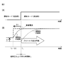
図2は、本発明の実施例による機械学習装置の動作原理を説明する図であって、(A)は誘導電動機の運転モードを示し、(B)は誘導電動機に流れる励磁電流およびこの励磁電流によって発生する磁束を示す。 2A and 2B are diagrams for explaining the operation principle of the machine learning apparatus according to the embodiment of the present invention. FIG. 2A shows an operation mode of the induction motor, and FIG. 2B shows an excitation current flowing through the induction motor and the excitation current. Shows the magnetic flux generated by.
既に説明したように、誘導電動機に流れる励磁電流によって発生する磁束は、励磁電流に対して誘導電動機の回路定数を時定数とする1次遅れで変化する。本発明の実施例では、この磁束の1次遅れを考慮し、誘導電動機の運転モードが低負荷運転モードから高負荷運転モードに切り換えられる時点よりも前に励磁を開始して高負荷運転モードに切り換えられた時点になったときにフルトルクが得られるような最大磁束が発生するよう、励磁開始タイミングを調整し、かつ高負荷運転モードの前に実行される低負荷運転モードの励磁電流指令を調整する。具体的には次の通りである。 As already described, the magnetic flux generated by the exciting current flowing through the induction motor changes with a first-order delay with the circuit constant of the induction motor as a time constant with respect to the exciting current. In the embodiment of the present invention, in consideration of the first-order lag of the magnetic flux, excitation is started before the time when the operation mode of the induction motor is switched from the low load operation mode to the high load operation mode, and the high load operation mode is set. Adjust the excitation start timing and adjust the excitation current command in the low-load operation mode that is executed before the high-load operation mode so that the maximum magnetic flux that can obtain full torque is generated at the time of switching. To do. Specifically, it is as follows.
図2(A)に示すように、時刻t1で誘導電動機の運転モードが低負荷運転モードから高負荷運転モードに切り換えられる場合を考える。一般に、励磁開始タイミングは、低負荷運転モードから高負荷運転モードに切り換わるタイミング(すなわち時刻t1)と同じになるように予め設定されているが、本発明の実施例では、図2(B)に示すように、誘導電動機の運転モードが低負荷運転モードから高負荷運転モードに切り換えられる時刻t1よりも時間Δtだけ先立って励磁を開始し、高負荷運転モードに切り換えられた時点になったときにフルトルクが得られるような最大磁束が発生するようにし、磁束立ち上げ待ち時間を無くすようにする。すなわち、高負荷運転モードについて予め設定された励磁開始タイミングを、励磁開始タイミング調整分Δtを用いて調整する。またさらに、本発明の実施例では、高負荷運転モードの前に実行される低負荷運転モードにおける励磁電流指令を、低負荷運転モードについて予め設定された励磁電流指令よりもΔIだけ高く設定することで、低負荷運転モードにおいて誘導電動機に流れる励磁電流を従前よりも多く流れるようにし、高負荷運転モードに対応する最大磁束に到達するまでの時間が短縮されるようにする。すなわち、ΔIを励磁電流指令増分とし、これを高負荷運転モードの前に実行される低負荷運転モードにおける励磁電流指令に加える。図2(B)では、誘導電動機に流れる励磁電流を一点破線で示し、本発明を適用した調整後の磁束を実線で示し、本発明を適用しない調整前の磁束を破線で示している。 As shown in FIG. 2A, consider a case where the operation mode of the induction motor is switched from the low load operation mode to the high load operation mode at time t 1 . In general, the excitation start timing is set in advance to be the same as the timing at which the low load operation mode is switched to the high load operation mode (that is, time t 1 ). In the embodiment of the present invention, FIG. As shown in FIG. 5B, excitation starts for a time Δt before time t 1 when the operation mode of the induction motor is switched from the low load operation mode to the high load operation mode, and the time when the operation mode is switched to the high load operation mode is reached. The maximum magnetic flux is generated so that full torque can be obtained at the time, and the waiting time for raising the magnetic flux is eliminated. That is, the excitation start timing preset for the high load operation mode is adjusted using the excitation start timing adjustment Δt. Furthermore, in the embodiment of the present invention, the excitation current command in the low load operation mode executed before the high load operation mode is set higher by ΔI than the excitation current command preset in the low load operation mode. Thus, the excitation current flowing through the induction motor in the low load operation mode is made to flow more than before, and the time until the maximum magnetic flux corresponding to the high load operation mode is reached is shortened. That is, ΔI is set as an excitation current command increment, which is added to the excitation current command in the low load operation mode executed before the high load operation mode. In FIG. 2B, the exciting current flowing through the induction motor is indicated by a one-dot broken line, the magnetic flux after adjustment to which the present invention is applied is indicated by a solid line, and the magnetic flux before adjustment to which the present invention is not applied is indicated by a broken line.
本発明の実施例では、上述した所定の運転モード(高負荷運転モード)の実行前の運転モード(低負荷運転モード)について予め設定されていた電動機の励磁電流指令に加えられる励磁電流指令増分ΔIおよび所定の運転モード(高負荷運転モード)について予め設定されていた励磁開始タイミングを調整するための励磁開始タイミング調整分Δtを、機械学習装置1が自ら学習して調整していくことで、磁束立ち上げ待ち時間を無くし、誘導電動機の磁束が最適になるようにする。 In the embodiment of the present invention, the excitation current command increment ΔI added to the excitation current command of the motor set in advance for the operation mode (low load operation mode) before execution of the predetermined operation mode (high load operation mode) described above. and the excitation start timing adjustment amount Δt for adjusting the excitation start timing which has been previously set for a given operating mode (high-load operation mode), in the machine learning device 1 Ikuko adjusted by themselves learning, flux Eliminate start-up waiting time and optimize the induction motor magnetic flux.
図3は、本発明の実施例による機械学習方法の動作フローを示すフローチャートである。電動機制御装置による電動機の磁束制御のための励磁電流指令および磁束制御による磁束の立ち上げ開始のタイミングである励磁開始タイミングに関連付けられる条件を学習する機械学習方法は、状態観測ステップS101と、機械学習ステップS102とを備える。 FIG. 3 is a flowchart showing an operation flow of the machine learning method according to the embodiment of the present invention. The machine learning method for learning the conditions associated with the excitation current command for the magnetic flux control of the motor by the motor control device and the excitation start timing that is the timing of starting the magnetic flux by the magnetic flux control includes state observation step S101, machine learning Step S102.
状態観測ステップS101は、状態観測部11により実行されるものであり、すなわち、所定の運転モードの開始指令時点から電動機の磁束が所定の運転モードに対応する最大磁束に到達するまでに要する時間である磁束立ち上げ待ち時間に関するデータと、電動機がオーバーヒートしたことを示すオーバーヒートアラームの発生の有無に関するデータと、のうちの少なくとも1つから構成される状態変数を観測する。 The state observing step S101 is executed by the state observing unit 11, that is, the time required for the magnetic flux of the motor to reach the maximum magnetic flux corresponding to the predetermined operation mode from the start command point of the predetermined operation mode. A state variable composed of at least one of data related to a certain magnetic flux rise waiting time and data related to the presence or absence of an overheat alarm indicating that the motor has overheated is observed.
機械学習ステップS102は、学習部12により実行されるものであり、状態変数によって構成される訓練データセットに従って、所定の運転モードの実行前の運転モードについて予め設定されていた電動機の励磁電流指令に加えられる励磁電流指令増分ΔI、および、所定の運転モードについて予め設定されていた励磁開始タイミングを調整するための励磁開始タイミング調整分Δtに関連付けられる条件を学習する。
The machine learning step S102 is executed by the
学習部12が用いる学習アルゴリズムはどのようなものを用いてもよい。一例として、強化学習(Reinforcement Learning)を適用した場合について説明する。強化学習は、ある環境内におけるエージェント(行動主体)が、現在の状態を観測し、取るべき行動を決定する、というものである。エージェントは行動を選択することで環境から報酬を得て、一連の行動を通じて報酬が最も多く得られるような方策を学習する。強化学習の代表的な手法として、Q学習(Q−learning)やTD学習(TD−learning)が知られている。例えば、Q学習の場合、行動価値関数Q(s,a)の一般的な更新式(行動価値テーブル)は式1で表される。
Any learning algorithm used by the

式1において、stは時刻tにおける環境を表し、atは時刻tにおける行動を表す。行動atにより、環境はst+1に変わる。rt+1はその環境の変化によってもらえる報酬(reward)を表し、γは割引率を表し、αは学習係数を表す。Q学習を適用した場合、励磁電流指令増分ΔIおよび励磁開始タイミング調整分Δtが行動atとなる。 In Equation 1, s t represents the environment at time t, a t represents the behavior in time t. By the action a t, the environment is changed to s t + 1. r t + 1 represents a reward obtained by a change in the environment, γ represents a discount rate, and α represents a learning coefficient. When applying the Q-learning, the excitation current command increment ΔI and exciting start timing adjustment amount Δt is an action a t.
図4は、本発明の実施例による、強化学習を用いた機械学習装置の原理ブロック図である。学習部12は、報酬計算部21と関数更新部22とを備える。報酬計算部21は、状態変数に基づいて報酬を計算する。関数更新部22は、報酬に基づいて、励磁電流指令増分ΔIおよび励磁開始タイミング調整分Δtを変更するための関数を更新する。例えばQ学習の場合、式1で表される行動価値関数Q(s,a)を、行動atである励磁電流指令増分ΔIおよび励磁開始タイミング調整分Δtを変更するための関数として用いる。なお、これら以外の構成要素については図1に示す構成要素と同様であるので、同一の構成要素には同一符号を付して当該構成要素についての詳細な説明は省略する。
FIG. 4 is a principle block diagram of a machine learning apparatus using reinforcement learning according to an embodiment of the present invention. The
図5は、本発明の実施例による、強化学習を用いた機械学習方法の動作フローを示すフローチャートである。 FIG. 5 is a flowchart illustrating an operation flow of a machine learning method using reinforcement learning according to an embodiment of the present invention.
まず、状態観測ステップS101において、状態観測部11は、所定の運転モードの開始指令時点から電動機の磁束が所定の運転モードに対応する最大磁束に到達するまでに要する時間である磁束立ち上げ待ち時間に関するデータと、電動機がオーバーヒートしたことを示すオーバーヒートアラームの発生の有無に関するデータと、のうちの少なくとも1つから構成される状態変数を観測する。 First, in the state observing step S101, the state observing unit 11 waits for the magnetic flux rise time, which is the time required for the motor magnetic flux to reach the maximum magnetic flux corresponding to the predetermined operation mode from the start command point of the predetermined operation mode. State variables including at least one of the following data and data on the presence or absence of an overheat alarm indicating that the motor has overheated are observed.
次いで、報酬計算ステップS102−1において、報酬計算部21は、ステップS101において観測された状態変数に基づいて報酬を計算する。
Next, in the reward calculation step S102-1, the
次いで、関数更新ステップS102−2において、関数更新部22は、報酬に基づいて、励磁電流指令増分ΔIおよび励磁開始タイミング調整分Δtを変更するための関数を更新する。
Next, in function update step S102-2, the
続いて、上述の機械学習装置を備える電動機制御装置について説明する。ここでは一例として、学習部の学習アルゴリズムとして強化学習を用いた場合について説明する。 Subsequently, an electric motor control device including the above-described machine learning device will be described. Here, as an example, a case where reinforcement learning is used as the learning algorithm of the learning unit will be described.
図6は、本発明の実施例による機械学習装置を備える電動機制御装置を示す原理ブロック図である。ここでは、1個の誘導電動機104を駆動制御する電動機制御装置1000について説明する。また、誘導電動機104の運転モードとして、低負荷運転モードと高負荷運転モードが交互に実行されるものとする。
FIG. 6 is a principle block diagram illustrating an electric motor control device including a machine learning device according to an embodiment of the present invention. Here, an electric
電動機制御装置1000は、その主回路構成として、順変換器101と、逆変換器102と、DCリンクコンデンサ105とを備える。電動機制御装置1000の三相交流入力側には交流電源103が接続され、電動機制御装置1000の交流電動機側には三相の誘導電動機104が接続される。
The
順変換器101は、交流電源103側から供給された交流電力を直流電力に変換してDCリンクへ出力する。本発明では、用いられる順変換器101の実施形態は特に限定されず、例えばダイオード整流器、あるいはPWM制御方式の整流回路などがある。
The
逆変換器102は、DCリンクに接続され、DCリンクにおける直流電力を交流電力に変換して誘導電動機104へ供給するものであるが、一般的には交直双方向に変換可能である電力変換器である。すなわち、逆変換器102は、DCリンクの直流電力と誘導電動機104の駆動電力もしくは回生電力である交流電力との間で双方向に電力変換することができるものであり、電動機制御部14から受信した電動機駆動指令に従い、直流電力を交流電力に変換する回生動作(逆変換動作)および交流電力を直流電力に変換する力行動作(順変換動作)のいずれかを行う。具体的には、逆変換器102は、DCリンク側から供給される直流電力を、電動機制御部14から受信した電動機駆動指令に基づき内部のスイッチング素子をスイッチング動作させ、誘導電動機104を駆動するための所望の電圧および所望の周波数の三相交流電力に変換する。これにより、誘導電動機104は、供給された電圧可変および周波数可変の三相交流電力に基づいて動作することになる。また、誘導電動機104の減速時には回生電力が発生するが、この場合は電動機制御部14から受信した電動機駆動指令に基づき、誘導電動機104で発生した交流の回生電力を直流電力へ変換してDCリンクへ戻す。逆変換器102は、例えばPWMインバータなどのような、スイッチング素子およびこれに逆並列に接続されたダイオードのブリッジ回路からなる。
The
また、電動機制御装置1000は、その制御系および測定系として、図4および図5を参照して説明した強化学習を用いた機械学習装置1と、意思決定部13と、磁束制御部37を有する電動機制御部14と、運転モード指令入力部31と、電流検出部32と、磁束計算部33と、温度測定部34と、アラーム出力部35と、時間測定部36とを備える。
In addition, the
運転モード指令入力部31は、所定の運転モード(高負荷運転モード)の開始指令が入力される。すなわち、この開始指令は、誘導電動機104の運転モードを低負荷運転モードから高負荷運転モードへ切り換える指令であり、電動機制御部14から入力される。
The operation mode command input unit 31 receives a start command for a predetermined operation mode (high load operation mode). That is, this start command is a command for switching the operation mode of the
電流検出部32は、誘導電動機104に流れる実電流を検出する。
The
磁束計算部33は、電流検出部32により検出された誘導電動機104の実電流から、誘導電動機104の磁束を計算する。
The
温度測定部34は、誘導電動機104の温度を測定する。
The
アラーム出力部35は、温度測定部34により測定された温度がオーバーヒート温度に達したとき、オーバーヒートアラームを出力する。
The
時間測定部36は、所定の運転モード(高負荷運転モード)の開始指令時点から誘導電動機104の磁束が所定の運転モードに対応する最大磁束に到達するまでに要する時間である磁束立ち上げ待ち時間を測定する。
The
電動機制御部14は、誘導電動機104をベクトル制御するための磁束制御部37を備える。磁束制御部37は、磁束計算部33により算出された誘導電動機104の磁束を、各運転モードに対応する磁束に追従させる磁束制御を行う。電動機制御部14の詳細については後述する。
The electric
機械学習装置1は、状態観測部11と学習部12とを備える。また、学習部12は、報酬計算部21と関数更新部22とを備える。
The machine learning device 1 includes a state observation unit 11 and a
状態観測部11は、所定の運転モードの開始指令時点から誘導電動機104の磁束が所定の運転モードに対応する最大磁束に到達するまでに要する時間である磁束立ち上げ待ち時間に関するデータと、誘導電動機104がオーバーヒートしたことを示すオーバーヒートアラームの発生の有無に関するデータと、のうちの少なくとも1つから構成される状態変数を観測する。観測された状態変数は訓練データセットとして学習部12における学習に用いられる。磁束立ち上げ待ち時間は、磁束計算部33により算出された誘導電動機104の磁束から、時間測定部36により測定される。オーバーヒートアラームは、アラーム出力部35から出力される。
The state observing unit 11 includes data relating to a magnetic flux rise waiting time which is a time required for the magnetic flux of the
学習部12内の報酬計算部21は、状態観測部11により観測された状態変数に基づいて、報酬を計算する。
The
磁束立ち上げ待ち時間に関するデータを状態変数とした場合、報酬計算部21は、状態観測部11によりオーバーヒートアラームの発生無しを観測したときにおいて、状態観測部11により観測された磁束立ち上げ待ち時間が規定時間内であるとき報酬を増やす。また、報酬計算部21は、状態観測部11により観測された磁束立ち上げ待ち時間が規定時間外であるとき報酬を減らす。このように磁束立ち上げ待ち時間が規定時間内であるとき報酬を増やし規定時間外であるとき報酬を減らすのは、磁束立ち上げ待ち時間が短いほど、誘導電動機104の磁束を最適に制御できているということを意味するからである。
When the data related to the magnetic flux rise waiting time is used as the state variable, the
誘導電動機104がオーバーヒートしたことを示すオーバーヒートアラームの発生の有無に関するデータを状態変数とした場合、報酬計算部21は、所定の運転モード(高負荷運転モード)の開始後、状態観測部11によりオーバーヒートアラームの発生有りを観測したときは報酬を減らす。このようにオーバーヒートアラームの発生有りを観測したときは報酬を減らすのは、機械学習装置1による学習の結果として誘導電動機104に発生した磁束を用いたために、誘導電動機104がオーバーヒートすることになったからであり、好ましい学習結果とはいえないからである。
When the data regarding the presence or absence of the occurrence of an overheat alarm indicating that the
学習部12内の関数更新部22は、報酬計算部21によって算出された報酬に基づいて、励磁電流指令増分ΔIおよび励磁開始タイミング調整分Δtを変更するための関数を更新する。例えばQ学習の場合、式1で表される行動価値関数Q(s,a)を励磁電流指令増分ΔIおよび励磁開始タイミング調整分Δtを変更するための関数として用いる。
The
意思決定部13は、学習部12が訓練データセットに従って学習した結果に基づいて、現在の状態変数の入力に応答して、励磁電流指令増分ΔIおよび励磁開始タイミング調整分Δtを決定する。本実施例では、一例として学習アルゴリズムとして強化学習を用いているので、学習部12内の報酬計算部21によって算出された報酬に基づいて学習部12内の関数更新部22は励磁電流指令増分ΔIおよび励磁開始タイミング調整分Δtを変更するための関数を更新し、意思決定部13は、更新された関数に基づき、報酬が最も多く得られる励磁電流指令増分ΔIおよび励磁開始タイミング調整分Δtを選択する。
The
電動機制御部14内の磁束制御部37では、所定の運転モード(高負荷運転モード)の実行前の運転モード(低負荷運転モード)について予め設定されていた励磁電流指令に、意思決定部13により決定された励磁電流指令増分ΔIを加えることで、低負荷運転モードについての新たなる励磁電流指令が得られる(図2参照。)。また、誘導電動機の運転モードが低負荷運転モードから高負荷運転モードに切り換えられる時刻よりも時間Δtだけ先立った時刻を、高負荷運転モードについての新たなる励磁開始タイミングとする(図2参照。)。すなわち、磁束制御部37は、所定の運転モード(高負荷運転モード)の実行前の運転モード(低負荷運転モード)について予め設定されていた励磁電流指令に、意思決定部13により決定された励磁電流指令増分ΔIを加えることにより得られた指令と、意思決定部13により決定された励磁開始タイミング調整分Δtにより調整された励磁開始タイミングとに基づいて、磁束計算部33により算出された誘導電動機104の磁束を所定の運転モード(高負荷運転モード)に対応する磁束に追従させる磁束制御を行う。磁束制御部37の磁束制御により、磁束指令が生成される。
In the magnetic
電動機制御部14は、磁束制御部37が生成した磁束指令に基づいて、所定の速度指令、誘導電動機104の動作プログラム、逆変換器102の交流電動機側の交流電流もしくは交流電圧および/または誘導電動機104の回転速度などを用いて、誘導電動機104の速度、トルク、もしくは回転子の位置を制御するための駆動指令として、交流電力を直流電力に変換する力行動作(順変換動作)および直流電力を交流電力に変換する回生動作(逆変換動作)のいずれかを、逆変換器102に対して指令する。
Based on the magnetic flux command generated by the magnetic
図7は、本発明の実施例による、強化学習を用いた機械学習装置を備える電動機制御装置の動作フローを示すフローチャートである。 FIG. 7 is a flowchart showing an operation flow of the motor control device including the machine learning device using reinforcement learning according to the embodiment of the present invention.
一般に、強化学習では行動の初期値はランダムに選択される。本発明の実施例では、ステップS201において、行動である励磁電流指令増分ΔIおよび励磁開始タイミング調整分Δtをランダムに選択する。 Generally, in reinforcement learning, the initial value of action is selected at random. In the embodiment of the present invention, in step S201, the excitation current command increment ΔI and the excitation start timing adjustment Δt, which are actions, are randomly selected.
ステップS202では、電動機制御部14は、逆変換器102に対し、設定された励磁電流指令増分ΔIおよび励磁開始タイミング調整分Δtを用いて磁束制御部37が生成した磁束指令に基づいて、所定の速度指令、誘導電動機104の動作プログラム、逆変換器102の交流電動機側の交流電流もしくは交流電圧および/または誘導電動機104の回転速度などを用いて、誘導電動機104の速度、トルク、もしくは回転子の位置を制御するための駆動指令として、交流電力を直流電力に変換する力行動作(順変換動作)および直流電力を交流電力に変換する回生動作(逆変換動作)のいずれかを、逆変換器102に対して指令する。これにより誘導電動機104は駆動することになる。本実施例では、誘導電動機104の運転モードとして、低負荷運転モードと高負荷運転モードが交互に実行され、低負荷運転モードと高負荷運転モードとからなる1組を1サイクルとする。この間、電流検出部32は誘導電動機104に流れる実電流を検出し、磁束計算部33は誘導電動機104の実電流から誘導電動機104の磁束を計算し、温度測定部34は誘導電動機104の温度を測定し、アラーム出力部35は温度測定部34により測定された温度がオーバーヒート温度に達したときはオーバーヒートアラームを出力し、時間測定部36は磁束立ち上げ待ち時間を測定する。
In step S202, the
ステップS203において、状態観測部11は、磁束立ち上げ待ち時間に関するデータと、誘導電動機104がオーバーヒートしたことを示すオーバーヒートアラームの発生の有無に関するデータと、のうちの少なくとも1つから構成される状態変数を観測する。なお、本実施例では、一例としてこれら2つのデータを状態変数としたが、これら2つのデータのうち少なくとも1つを状態変数とすればよい。
In step S <b> 203, the state observing unit 11 is a state variable including at least one of data related to the magnetic flux rise waiting time and data related to the presence or absence of an overheat alarm indicating that the
ステップS204では、低負荷運転モードと高負荷運転モードとからなる1サイクルが終了したか否かが判定される。この判定は、例えば電動機制御部14によって実行される。
In step S204, it is determined whether or not one cycle consisting of the low load operation mode and the high load operation mode has ended. This determination is executed by, for example, the
ステップS204において低負荷運転モードと高負荷運転モードとからなる1サイクルが終了したと判定されると、ステップS205へ進む。 If it is determined in step S204 that one cycle consisting of the low load operation mode and the high load operation mode has been completed, the process proceeds to step S205.
ステップS205では、状態観測部11は、誘導電動機104がオーバーヒートしたことを示すオーバーヒートアラームの発生の有無に関するデータに基づいて、オーバーヒートアラームが発生したか否かを判別する。状態観測部11によりオーバーヒートアラームが観測されたときは、ステップS208において報酬計算部21は報酬を減らす。一方、状態観測部11によりオーバーヒートアラームが観測されなかったときはステップS206へ進む。
At step S20 5, the state observer 11, the
ステップS206では、状態観測部11は、磁束立ち上げ待ち時間に関するデータに基づき、観測した磁束立ち上げ待ち時間が規定時間内であるか否かを判別する。状態観測部11により磁束立ち上げ待ち時間が規定時間内であることが観測されたときは、ステップS207において報酬計算部21は報酬を増やす。一方、状態観測部11により磁束立ち上げ待ち時間が規定時間外であることが観測されたときは、ステップS208において報酬計算部21は報酬を減らす。
In step S <b> 206, the state observation unit 11 determines whether or not the observed magnetic flux rise waiting time is within a specified time based on data regarding the magnetic flux rise waiting time. When the state observation unit 11 observes that the magnetic flux rise waiting time is within the specified time, the
ステップS209では、関数更新部22は、報酬計算部21によって算出された報酬に基づいて、報酬計算部21によって算出された報酬に基づいて、励磁電流指令増分ΔIおよび励磁開始タイミング調整分Δtを変更するための関数を更新する。
In step S209, the
続くステップS210では、意思決定部13は、ステップS209において更新された関数に基づいて、報酬が最も多く得られる励磁電流指令増分ΔIおよび励磁開始タイミング調整分Δtを選択する。その後、ステップS202へ戻り、これ以降、ステップS202〜S210の処理が繰り返し実行される。これにより、機械学習装置1は、誘導電動機104の磁束が最適になるような励磁電流指令増分ΔIおよび励磁開始タイミング調整分Δtを学習していく。なお、訓練データセットを、複数の順変換器101から取得してもよく、この場合、学習部12は、複数の順変換器101に対して取得される訓練データセットに従って、ステップS201〜S210の処理を繰り返し実行し、励磁電流指令増分ΔIおよび励磁開始タイミング調整分Δtを学習していく。複数の順変換器101に対して訓練データセットを取得することで機械学習装置1の学習精度をさらに向上させることができる。
In the subsequent step S210, the
なお、上述した状態観測部11、学習部12、および意思決定部13は、例えばソフトウェアプログラム形式で構築されてもよく、あるいは各種電子回路とソフトウェアプログラムとの組み合わせで構築されてもよい。例えばこれらをソフトウェアプログラム形式で構築する場合は、電動機制御装置1000内にある演算処理装置をこのソフトウェアプログラムに従って動作させることで上述の各部の機能が実現される。またあるいは、状態観測部11および学習部12を備える機械学習装置1を、各部の機能を実現するソフトウェアプログラムを書き込んだ半導体集積回路として実現してもよい。またあるいは、状態観測部11および学習部12を備える機械学習装置1のみならず意思決定部13も含めた形で、各部の機能を実現するソフトウェアプログラムを書き込んだ半導体集積回路を実現してもよい。
In addition, the state observation part 11, the learning
また、本発明による機械学習処理は、電動機制御装置1000が誘導電動機104の駆動制御のために本来的に備える電流検出部32により検出される誘導電動機104の実電流に関するデータおよび温度測定部34により測定される誘導電動機104の温度に関するデータを用いて実行されるので、従来技術のように新たなハードウェア装置を設ける必要がないことから、既存の電動機制御装置にも後付けで適用することも可能である。この場合、機械学習装置1や意思決定部13の各部の機能を実現するソフトウェアプログラムを書き込んだ半導体集積回路を当該既存の電動機制御装置に組み込んだり、機械学習装置1や意思決定部13の各部の機能を実現するソフトウェアプログラムそのものを当該既存の電動機制御装置内の演算処理装置に追加的にインストールすればよい。また、ある電動機制御装置に関して励磁電流指令増分ΔIおよび励磁開始タイミング調整分Δtを学習した機械学習装置1を、これとは別の電動機制御装置に取り付け、当該別の電動機駆動装置に関して励磁電流指令増分ΔIおよび励磁開始タイミング調整分Δtを再学習して更新するようにしてもよい。
In addition, the machine learning process according to the present invention is performed by the data related to the actual current of the
1 機械学習装置
11 状態観測部
12 学習部
13 意思決定部
14 電動機制御部
21 報酬計算部
22 関数更新部
31 運転モード指令入力部
32 電流検出部
33 磁束計算部
34 温度測定部
35 アラーム出力部
36 時間測定部
37 磁束制御部
101 順変換器
102 逆変換器
104 誘導電動機
105 DCリンクコンデンサ
1000 電動機制御装置
DESCRIPTION OF SYMBOLS 1 Machine learning apparatus 11
Claims (9)
所定の運転モードの開始指令時点から電動機の磁束が前記所定の運転モードに対応する最大磁束に到達するまでに要する時間である磁束立ち上げ待ち時間に関するデータと、電動機がオーバーヒートしたことを示すオーバーヒートアラームの発生の有無に関するデータと、のうちの少なくとも1つから構成される状態変数を観測する状態観測部と、
前記状態変数によって構成される訓練データセットに従って、前記所定の運転モードの実行前の運転モードについて予め設定されていた電動機の励磁電流指令に加えられる励磁電流指令増分、および、前記所定の運転モードについて予め設定されていた励磁開始タイミングを調整するための励磁開始タイミング調整分、に関連付けられる条件を学習する学習部と、
を備えることを特徴とする機械学習装置。 A machine learning device for learning an excitation current command for controlling magnetic flux of an electric motor by an electric motor control device and a condition associated with an excitation start timing which is a timing of starting the magnetic flux by the magnetic flux control,
Data on the magnetic flux rise waiting time, which is the time required for the motor magnetic flux to reach the maximum magnetic flux corresponding to the predetermined operation mode from the start command point of the predetermined operation mode, and an overheat alarm indicating that the motor has overheated A state observing unit for observing a state variable composed of at least one of data on the occurrence of
According to the training data set constituted by the state variables, the excitation current command increment added to the excitation current command of the motor set in advance for the operation mode before execution of the predetermined operation mode, and the predetermined operation mode A learning unit for learning conditions associated with the excitation start timing adjustment for adjusting the excitation start timing set in advance;
A machine learning device comprising:
前記状態変数に基づいて報酬を計算する報酬計算部と、
前記報酬に基づいて、前記励磁電流指令増分および前記励磁開始タイミング調整分を変更するための関数を更新する関数更新部と、
を備える請求項1に記載の機械学習装置。 The learning unit
A reward calculation unit for calculating a reward based on the state variable;
A function updating unit for updating a function for changing the excitation current command increment and the excitation start timing adjustment based on the reward;
The machine learning device according to claim 1, comprising:
前記所定の運転モードの開始指令が入力される運転モード指令入力部と、
電動機に流れる実電流を検出する電流検出部と、
前記電流検出部により検出された前記電動機の実電流から、電動機の磁束を計算する磁束計算部と、
電動機の温度を測定する温度測定部と、
前記温度測定部により測定された温度がオーバーヒート温度に達したとき、オーバーヒートアラームを出力するアラーム出力部と、
前記磁束立ち上げ待ち時間を測定する時間測定部と、
前記磁束計算部により算出された電動機の磁束を前記所定の運転モードに対応する最大磁束に追従させる磁束制御を行う磁束制御部と、
前記学習部が前記訓練データセットに従って学習した結果に基づいて、現在の前記状態変数の入力に応答して、前記励磁電流指令増分および前記励磁開始タイミング調整分を決定する意思決定部と、
をさらに備え、
前記磁束制御部は、前記励磁電流指令に前記意思決定部により決定された前記励磁電流指令増分を加えることにより得られた指令と、前記意思決定部により決定された前記励磁開始タイミング調整分により調整された励磁開始タイミングとに基づいて、前記磁束制御を行うことを特徴とする電動機制御装置。 An electric motor control device comprising the machine learning device according to any one of claims 1 to 6,
An operation mode command input unit to which a start command of the predetermined operation mode is input;
A current detector that detects the actual current flowing through the motor;
From the actual current of the motor detected by the current detector, a magnetic flux calculator that calculates the magnetic flux of the motor;
A temperature measuring unit for measuring the temperature of the motor;
An alarm output unit for outputting an overheat alarm when the temperature measured by the temperature measurement unit reaches an overheat temperature;
A time measuring unit for measuring the magnetic flux rise waiting time;
A magnetic flux control unit that performs magnetic flux control for causing the magnetic flux of the motor calculated by the magnetic flux calculation unit to follow the maximum magnetic flux corresponding to the predetermined operation mode;
A decision-making unit that determines the excitation current command increment and the excitation start timing adjustment in response to an input of the current state variable based on a result learned by the learning unit according to the training data set;
Further comprising
The magnetic flux control unit adjusts the command obtained by adding the excitation current command increment determined by the decision deciding unit to the excitation current command and the excitation start timing adjustment determined by the decision deciding unit. An electric motor control device that performs the magnetic flux control based on the excitation start timing.
所定の運転モードの開始指令時点から電動機の磁束が前記所定の運転モードに対応する最大磁束に到達するまでに要する時間である磁束立ち上げ待ち時間に関するデータと、電動機がオーバーヒートしたことを示すオーバーヒートアラームの発生の有無に関するデータと、のうちの少なくとも1つから構成される状態変数を観測する状態観測ステップと、
前記状態変数によって構成される訓練データセットに従って、前記所定の運転モードの実行前の運転モードについて予め設定されていた電動機の励磁電流指令に加えられる励磁電流指令増分、および、前記所定の運転モードについて予め設定されていた励磁開始タイミングを調整するための励磁開始タイミング調整分、に関連付けられる条件を学習する学習ステップと、
を備えることを特徴とする機械学習方法。 A machine learning method for learning an excitation current command for controlling magnetic flux of an electric motor by an electric motor control device and a condition associated with an excitation start timing which is a timing of starting the magnetic flux by the magnetic flux control,
Data on the magnetic flux rise waiting time, which is the time required for the motor magnetic flux to reach the maximum magnetic flux corresponding to the predetermined operation mode from the start command point of the predetermined operation mode, and an overheat alarm indicating that the motor has overheated A state observation step of observing a state variable composed of at least one of data on the occurrence of
According to the training data set constituted by the state variables, the excitation current command increment added to the excitation current command of the motor set in advance for the operation mode before execution of the predetermined operation mode, and the predetermined operation mode A learning step for learning conditions associated with the excitation start timing adjustment for adjusting the excitation start timing set in advance;
A machine learning method comprising:
Priority Applications (4)
| Application Number | Priority Date | Filing Date | Title |
|---|---|---|---|
| JP2015167875A JP6088604B1 (en) | 2015-08-27 | 2015-08-27 | Electric motor control device having magnetic flux control unit, machine learning device and method thereof |
| US15/241,002 US9768716B2 (en) | 2015-08-27 | 2016-08-18 | Motor control apparatus provided with magnetic flux control unit, and machine learning apparatus and method thereof |
| CN201610697181.7A CN106487298B (en) | 2015-08-27 | 2016-08-19 | Control device of electric motor, rote learning devices and methods therefor |
| DE102016010056.7A DE102016010056B4 (en) | 2015-08-27 | 2016-08-19 | Motor control device provided with a magnetic flux control unit and machine learning device, and method thereof |
Applications Claiming Priority (1)
| Application Number | Priority Date | Filing Date | Title |
|---|---|---|---|
| JP2015167875A JP6088604B1 (en) | 2015-08-27 | 2015-08-27 | Electric motor control device having magnetic flux control unit, machine learning device and method thereof |
Publications (2)
| Publication Number | Publication Date |
|---|---|
| JP6088604B1 true JP6088604B1 (en) | 2017-03-01 |
| JP2017046487A JP2017046487A (en) | 2017-03-02 |
Family
ID=58011419
Family Applications (1)
| Application Number | Title | Priority Date | Filing Date |
|---|---|---|---|
| JP2015167875A Active JP6088604B1 (en) | 2015-08-27 | 2015-08-27 | Electric motor control device having magnetic flux control unit, machine learning device and method thereof |
Country Status (4)
| Country | Link |
|---|---|
| US (1) | US9768716B2 (en) |
| JP (1) | JP6088604B1 (en) |
| CN (1) | CN106487298B (en) |
| DE (1) | DE102016010056B4 (en) |
Families Citing this family (13)
| Publication number | Priority date | Publication date | Assignee | Title |
|---|---|---|---|---|
| JP7059557B2 (en) * | 2017-10-06 | 2022-04-26 | 富士通株式会社 | Wind turbine control program, wind turbine control method, and wind turbine control device |
| JP6603285B2 (en) * | 2017-10-19 | 2019-11-06 | ファナック株式会社 | Motor control device |
| JP6740263B2 (en) | 2018-02-08 | 2020-08-12 | ファナック株式会社 | Machine learning device, servo motor control device, servo motor control system, and machine learning method |
| JP7090440B2 (en) * | 2018-03-16 | 2022-06-24 | 株式会社Lixil | Control systems, learning devices, control devices, and control methods |
| JP7090439B2 (en) * | 2018-03-16 | 2022-06-24 | 株式会社Lixil | Control systems, learning devices, control devices, and control methods |
| JP7090445B2 (en) * | 2018-03-20 | 2022-06-24 | 株式会社Lixil | Control systems, learning devices, control devices, and control methods |
| JP7090444B2 (en) * | 2018-03-20 | 2022-06-24 | 株式会社Lixil | Control systems, learning devices, and control methods |
| JP7090443B2 (en) * | 2018-03-20 | 2022-06-24 | 株式会社Lixil | Control systems, learning devices, and control methods |
| JP7090442B2 (en) * | 2018-03-20 | 2022-06-24 | 株式会社Lixil | Control systems, learning devices, and control methods |
| US20190042979A1 (en) * | 2018-06-28 | 2019-02-07 | Intel Corporation | Thermal self-learning with reinforcement learning agent |
| JP6828762B2 (en) * | 2019-03-15 | 2021-02-10 | ダイキン工業株式会社 | Machine learning device and magnetic bearing device |
| JP7235610B2 (en) * | 2019-07-05 | 2023-03-08 | ファナック株式会社 | Motor information acquisition system |
| JP7469063B2 (en) * | 2020-02-13 | 2024-04-16 | ファナック株式会社 | Learning device, control device, and learning method |
Family Cites Families (13)
| Publication number | Priority date | Publication date | Assignee | Title |
|---|---|---|---|---|
| JPH02131387A (en) * | 1988-11-09 | 1990-05-21 | Toshiba Corp | Temperature monitoring device for induction motor |
| JP2003044102A (en) * | 2001-08-01 | 2003-02-14 | Yaskawa Electric Corp | Learning control method |
| JP2004178492A (en) * | 2002-11-29 | 2004-06-24 | Mitsubishi Heavy Ind Ltd | Plant simulation method using enhanced learning method |
| JP2007164406A (en) * | 2005-12-13 | 2007-06-28 | Oita Univ | Decision-making system with learning mechanism |
| JP5167631B2 (en) * | 2006-11-30 | 2013-03-21 | 株式会社デンソー | Motor control method and motor control apparatus using the same |
| JP4793793B2 (en) * | 2007-03-15 | 2011-10-12 | トヨタ自動車株式会社 | Electric motor drive |
| JP4235233B2 (en) * | 2007-06-05 | 2009-03-11 | ファナック株式会社 | Electric motor control device |
| JP5516087B2 (en) * | 2010-06-01 | 2014-06-11 | 富士電機株式会社 | Induction motor control method |
| DE102010050344A1 (en) | 2010-11-05 | 2012-05-10 | Getrag Getriebe- Und Zahnradfabrik Hermann Hagenmeyer Gmbh & Cie Kg | Method for designing controller structure for field-oriented controlling induction machine i.e. synchronous machine, in power train i.e. hybrid drive train, of motor vehicle i.e. motor car, involves deriving dice to control machine |
| JP5815458B2 (en) * | 2012-04-20 | 2015-11-17 | 日本電信電話株式会社 | Reward function estimation device, reward function estimation method, and program |
| JP6089775B2 (en) * | 2013-02-26 | 2017-03-08 | 日産自動車株式会社 | Motor control device |
| JP6030978B2 (en) * | 2013-03-22 | 2016-11-24 | 東芝シュネデール・インバータ株式会社 | Inverter device and teaching method for inverter device |
| US9487104B2 (en) | 2013-12-02 | 2016-11-08 | GM Global Technology Operations LLC | Method and apparatus for controlling an electrically-powered torque machine of a powertrain system |
-
2015
- 2015-08-27 JP JP2015167875A patent/JP6088604B1/en active Active
-
2016
- 2016-08-18 US US15/241,002 patent/US9768716B2/en active Active
- 2016-08-19 CN CN201610697181.7A patent/CN106487298B/en active Active
- 2016-08-19 DE DE102016010056.7A patent/DE102016010056B4/en active Active
Also Published As
| Publication number | Publication date |
|---|---|
| CN106487298A (en) | 2017-03-08 |
| JP2017046487A (en) | 2017-03-02 |
| DE102016010056A1 (en) | 2017-03-02 |
| DE102016010056B4 (en) | 2023-12-28 |
| US9768716B2 (en) | 2017-09-19 |
| CN106487298B (en) | 2018-02-23 |
| US20170063261A1 (en) | 2017-03-02 |
Similar Documents
| Publication | Publication Date | Title |
|---|---|---|
| JP6088604B1 (en) | Electric motor control device having magnetic flux control unit, machine learning device and method thereof | |
| JP6140225B2 (en) | Motor control device having magnetic flux controller, machine learning device and method thereof | |
| JP5964488B1 (en) | Motor control device having protection operation control unit, machine learning device and method thereof | |
| JP6193961B2 (en) | Machine learning device and method for optimizing the smoothness of feed of a machine feed shaft, and motor control device equipped with the machine learning device | |
| JP5650814B1 (en) | Motor control device with feedforward control | |
| JP5956662B1 (en) | Motor control device for adjusting power regeneration, control device for forward converter, machine learning device and method thereof | |
| CN109462352B (en) | Motor control method, device and computer readable storage medium | |
| JP6288330B1 (en) | Electric motor control device and electric motor control method | |
| US20120056568A1 (en) | Motor driving apparatus having dc link voltage regulating function | |
| JP6059285B2 (en) | Induction motor controller | |
| JP6143984B1 (en) | Inverter device | |
| JP2016189668A (en) | Motor control device, motor control method, sewing machine and program thereof | |
| JP2015133878A (en) | Motor control device and motor control method | |
| JP2019083672A (en) | Inverter, and drive control method for motor | |
| EP2618480A2 (en) | Motor control device and air conditioner | |
| KR20120107481A (en) | Motor control system for a hoist drive | |
| JP6334017B1 (en) | Induction motor control device | |
| JP6769246B2 (en) | Electric motor control device | |
| US20130076284A1 (en) | Motor drive device, and motor drive method | |
| JP2008029189A (en) | Speed control device for electric motor | |
| JP2019097264A (en) | Motor drive device with current detector | |
| CN111052594A (en) | Power conversion device, motor control system, and parameter setting method thereof | |
| Singh et al. | Sliding mode control of a mechanical speed sensorless dc motor drive fed from a current controlled chopper | |
| KR20060012551A (en) | ANN Control System for Rotor Resistance Estimation of Induction Motors | |
| JP6539538B2 (en) | Electric car control device |
Legal Events
| Date | Code | Title | Description |
|---|---|---|---|
| A521 | Request for written amendment filed |
Free format text: JAPANESE INTERMEDIATE CODE: A523 Effective date: 20161129 |
|
| A977 | Report on retrieval |
Free format text: JAPANESE INTERMEDIATE CODE: A971007 Effective date: 20161221 |
|
| A975 | Report on accelerated examination |
Free format text: JAPANESE INTERMEDIATE CODE: A971005 Effective date: 20161220 |
|
| TRDD | Decision of grant or rejection written | ||
| A01 | Written decision to grant a patent or to grant a registration (utility model) |
Free format text: JAPANESE INTERMEDIATE CODE: A01 Effective date: 20170110 |
|
| A61 | First payment of annual fees (during grant procedure) |
Free format text: JAPANESE INTERMEDIATE CODE: A61 Effective date: 20170203 |
|
| R150 | Certificate of patent or registration of utility model |
Ref document number: 6088604 Country of ref document: JP Free format text: JAPANESE INTERMEDIATE CODE: R150 |