JP6080171B2 - Module system center semiconductor type primary power switching network - Google Patents
Module system center semiconductor type primary power switching network Download PDFInfo
- Publication number
- JP6080171B2 JP6080171B2 JP2014208634A JP2014208634A JP6080171B2 JP 6080171 B2 JP6080171 B2 JP 6080171B2 JP 2014208634 A JP2014208634 A JP 2014208634A JP 2014208634 A JP2014208634 A JP 2014208634A JP 6080171 B2 JP6080171 B2 JP 6080171B2
- Authority
- JP
- Japan
- Prior art keywords
- power
- primary power
- primary
- switching network
- mec
- Prior art date
- Legal status (The legal status is an assumption and is not a legal conclusion. Google has not performed a legal analysis and makes no representation as to the accuracy of the status listed.)
- Active
Links
- 239000004065 semiconductor Substances 0.000 title description 41
- 238000009826 distribution Methods 0.000 claims description 39
- 238000012546 transfer Methods 0.000 description 93
- 238000004891 communication Methods 0.000 description 56
- 239000004020 conductor Substances 0.000 description 47
- 230000003068 static effect Effects 0.000 description 44
- 239000002131 composite material Substances 0.000 description 28
- 238000000034 method Methods 0.000 description 23
- 230000006870 function Effects 0.000 description 20
- 230000007935 neutral effect Effects 0.000 description 15
- 230000004888 barrier function Effects 0.000 description 11
- 238000006243 chemical reaction Methods 0.000 description 8
- 238000009434 installation Methods 0.000 description 8
- 230000001360 synchronised effect Effects 0.000 description 8
- 230000007613 environmental effect Effects 0.000 description 7
- 239000000779 smoke Substances 0.000 description 7
- 238000004519 manufacturing process Methods 0.000 description 6
- 238000005192 partition Methods 0.000 description 6
- 230000007246 mechanism Effects 0.000 description 4
- XLYOFNOQVPJJNP-UHFFFAOYSA-N water Substances O XLYOFNOQVPJJNP-UHFFFAOYSA-N 0.000 description 4
- 230000006978 adaptation Effects 0.000 description 3
- 238000010586 diagram Methods 0.000 description 3
- 239000000446 fuel Substances 0.000 description 3
- 238000009413 insulation Methods 0.000 description 3
- 229910052751 metal Inorganic materials 0.000 description 3
- 239000002184 metal Substances 0.000 description 3
- 230000006855 networking Effects 0.000 description 3
- 238000012545 processing Methods 0.000 description 3
- 238000012360 testing method Methods 0.000 description 3
- 230000008901 benefit Effects 0.000 description 2
- 230000002457 bidirectional effect Effects 0.000 description 2
- 238000010276 construction Methods 0.000 description 2
- 230000001186 cumulative effect Effects 0.000 description 2
- 230000036541 health Effects 0.000 description 2
- 230000000670 limiting effect Effects 0.000 description 2
- 238000012423 maintenance Methods 0.000 description 2
- 239000000463 material Substances 0.000 description 2
- 230000036961 partial effect Effects 0.000 description 2
- 230000008569 process Effects 0.000 description 2
- 230000009467 reduction Effects 0.000 description 2
- 230000008439 repair process Effects 0.000 description 2
- 230000004044 response Effects 0.000 description 2
- 238000000926 separation method Methods 0.000 description 2
- 230000002159 abnormal effect Effects 0.000 description 1
- 238000007792 addition Methods 0.000 description 1
- 229910052782 aluminium Inorganic materials 0.000 description 1
- XAGFODPZIPBFFR-UHFFFAOYSA-N aluminium Chemical compound [Al] XAGFODPZIPBFFR-UHFFFAOYSA-N 0.000 description 1
- 230000009286 beneficial effect Effects 0.000 description 1
- 230000005540 biological transmission Effects 0.000 description 1
- 239000003990 capacitor Substances 0.000 description 1
- 238000010411 cooking Methods 0.000 description 1
- 238000005520 cutting process Methods 0.000 description 1
- 230000002950 deficient Effects 0.000 description 1
- 239000006185 dispersion Substances 0.000 description 1
- 230000005611 electricity Effects 0.000 description 1
- 238000004146 energy storage Methods 0.000 description 1
- 238000005516 engineering process Methods 0.000 description 1
- 238000003384 imaging method Methods 0.000 description 1
- 238000003780 insertion Methods 0.000 description 1
- 230000037431 insertion Effects 0.000 description 1
- 239000011810 insulating material Substances 0.000 description 1
- 230000002452 interceptive effect Effects 0.000 description 1
- 229910001095 light aluminium alloy Inorganic materials 0.000 description 1
- 230000007257 malfunction Effects 0.000 description 1
- 238000012986 modification Methods 0.000 description 1
- 230000004048 modification Effects 0.000 description 1
- 230000008520 organization Effects 0.000 description 1
- 238000010248 power generation Methods 0.000 description 1
- 238000002360 preparation method Methods 0.000 description 1
- 230000002829 reductive effect Effects 0.000 description 1
- 239000007787 solid Substances 0.000 description 1
- 238000005728 strengthening Methods 0.000 description 1
- 238000010998 test method Methods 0.000 description 1
- 229920001169 thermoplastic Polymers 0.000 description 1
- 239000004416 thermosoftening plastic Substances 0.000 description 1
Images


Classifications
-
- B—PERFORMING OPERATIONS; TRANSPORTING
- B60—VEHICLES IN GENERAL
- B60R—VEHICLES, VEHICLE FITTINGS, OR VEHICLE PARTS, NOT OTHERWISE PROVIDED FOR
- B60R16/00—Electric or fluid circuits specially adapted for vehicles and not otherwise provided for; Arrangement of elements of electric or fluid circuits specially adapted for vehicles and not otherwise provided for
- B60R16/02—Electric or fluid circuits specially adapted for vehicles and not otherwise provided for; Arrangement of elements of electric or fluid circuits specially adapted for vehicles and not otherwise provided for electric constitutive elements
- B60R16/03—Electric or fluid circuits specially adapted for vehicles and not otherwise provided for; Arrangement of elements of electric or fluid circuits specially adapted for vehicles and not otherwise provided for electric constitutive elements for supply of electrical power to vehicle subsystems or for
-
- H—ELECTRICITY
- H02—GENERATION; CONVERSION OR DISTRIBUTION OF ELECTRIC POWER
- H02J—CIRCUIT ARRANGEMENTS OR SYSTEMS FOR SUPPLYING OR DISTRIBUTING ELECTRIC POWER; SYSTEMS FOR STORING ELECTRIC ENERGY
- H02J3/00—Circuit arrangements for AC mains or AC distribution networks
- H02J3/007—Arrangements for selectively connecting the load or loads to one or several among a plurality of power lines or power sources
- H02J3/0073—Arrangements for selectively connecting the load or loads to one or several among a plurality of power lines or power sources for providing alternative feeding paths between load and source when the main path fails, e.g. transformers, busbars
-
- H—ELECTRICITY
- H02—GENERATION; CONVERSION OR DISTRIBUTION OF ELECTRIC POWER
- H02J—CIRCUIT ARRANGEMENTS OR SYSTEMS FOR SUPPLYING OR DISTRIBUTING ELECTRIC POWER; SYSTEMS FOR STORING ELECTRIC ENERGY
- H02J3/00—Circuit arrangements for AC mains or AC distribution networks
- H02J3/38—Arrangements for parallely feeding a single network by two or more generators, converters or transformers
- H02J3/381—Dispersed generators
-
- H—ELECTRICITY
- H02—GENERATION; CONVERSION OR DISTRIBUTION OF ELECTRIC POWER
- H02J—CIRCUIT ARRANGEMENTS OR SYSTEMS FOR SUPPLYING OR DISTRIBUTING ELECTRIC POWER; SYSTEMS FOR STORING ELECTRIC ENERGY
- H02J4/00—Circuit arrangements for mains or distribution networks not specified as AC or DC
Landscapes
- Engineering & Computer Science (AREA)
- Power Engineering (AREA)
- Mechanical Engineering (AREA)
- Supply And Distribution Of Alternating Current (AREA)
- Stand-By Power Supply Arrangements (AREA)
- Electric Propulsion And Braking For Vehicles (AREA)
Description
本明細書の中において提示される実施形態の分野は、モジュール式のビークルのアーキテクチャを対象とし、かつより具体的には、分散される電力及びデータの航空機のアーキテクチャの範囲内の電力スイッチングを対象とする。 The field of embodiments presented herein is directed to modular vehicle architectures, and more specifically to power switching within distributed power and data aircraft architectures. And
ほとんどの民間航空機は、電力装置及び通信装置を収納するための1以上の集中型の装置ベイを有する。電力及びデータは、航空機の範囲内の全ての機能を制御するために、航空機全体を通じて集中型の装置ベイから分散される。集中型の装置ベイは、航空機の中の1以上のセクション区切りを横断して、互いからずらされる。典型的には、一方の集中型の装置ベイが航空機の前方のセクションの中にあり、かつ他方が航空機の後方のセクションの中にある。 Most commercial aircraft have one or more centralized device bays for housing power and communication devices. Power and data are distributed from a centralized equipment bay throughout the aircraft to control all functions within the aircraft. Centralized device bays are offset from each other across one or more section breaks in the aircraft. Typically, one centralized device bay is in the front section of the aircraft and the other is in the rear section of the aircraft.
主要な推進エンジンにより駆動される発電機は、航空機のために3相の1次電力を発生する。1次電力は、先ず後方の装置ベイへ送られ、かつその後に航空機を通して前方の装置ベイに送られる。その後、1次電力は、様々な設備負荷を担うために航空機の残りの部分全てを通じて分散されるように中央に構成される。装置ベイの範囲内の集中型のバス電力制御ユニットは、航空機の中の全ての電力機能を制御する。集中型の変換の後に、2次電力が航空機の中の全ての装置負荷を担うために遠隔電力分散ユニットに送られ、又は直接に装置負荷に送られる。 A generator driven by the main propulsion engine generates three-phase primary power for the aircraft. Primary power is first sent to the rear device bay and then through the aircraft to the front device bay. The primary power is then centrally configured to be distributed throughout the remainder of the aircraft to carry various equipment loads. A centralized bus power control unit within the device bay controls all power functions in the aircraft. After centralized conversion, secondary power is sent to the remote power distribution unit to carry all equipment loads in the aircraft or directly to equipment loads.
航空機の全ての機能が、集中型の電力装置及び通信装置に依存する。 集中型の装置ベイからの電力又はデータのいずれかが断ち切られる場合、受信装置は待機状態になり、航空機搭乗員が対応するシステムの状態を決定することが困難になる。また、集中型の通信装置に対する及び集中型の通信装置からのピーク時における高い帯域幅需要のために、通信ネットワークの基幹回線は特大でなければならない。 All aircraft functions depend on centralized power and communication devices. If either power or data from the centralized device bay is cut off, the receiving device will be on standby, making it difficult for the aircraft crew to determine the state of the corresponding system. Also, because of the high bandwidth demand at and from the centralized communication device during peak times, the backbone of the communication network must be oversized.
複合材の航空機は、リターン電流経路又はネットワークとして働くアルミニウムのシャーシを有していない。結論として、ワイヤーの複合ネットワークが全ての回路のための電流リターン経路を提供するために加えられなければならないか、又は専用のリターンワイヤーが各々の装置負荷のために加えられなければならないか、のいずれかである。例えば、導線の配線が、複合材の航空機の幅にわたり横方向に延伸するように加えられなければならないのと同様に、複合材の航空機の長さに沿って長手方向に延伸するように加えられなければならない。この解決法は、費用、製造及び保守の複雑さ、増加された電圧降下、及び複合材の航空機にとって望ましくない重量を加える。それ故、配線を最小化することによって複合材の航空機の中の重量を低減させる試みは、複合材の航空機における増加された避雷保護構成要素及び他の理由に対する必要性から反対されてきた。 Composite aircraft do not have an aluminum chassis that serves as a return current path or network. In conclusion, whether a composite network of wires must be added to provide a current return path for all circuits, or a dedicated return wire must be added for each device load Either. For example, conductor wiring may be added to extend longitudinally along the length of the composite aircraft, just as it must be applied to extend laterally across the width of the composite aircraft. There must be. This solution adds cost, manufacturing and maintenance complexity, increased voltage drop, and undesired weight for composite aircraft. Therefore, attempts to reduce the weight of composite aircraft in aircraft by minimizing wiring have been opposed by the need for increased lightning protection components and other reasons in composite aircraft.
航空機の任意の他の導電性の金属構造と同様に、従来の航空機のアルミニウムのシャーシ(例えば、フレーム若しくは外板又はそれらの組み合わせを作り上げる構成要素)は、電圧基準点を線源分布接地点に返すための電流リターンネットワークを形成するように、一緒に結び付けられる。電流リターンネットワークはまた、身の安全の保護経路と同様に、避雷保護を提供する。しかしながら、シャーシが絶縁材から形成される複合材の航空機において、発電機から、前方及び後方の装置ベイへ、遠隔電力分散ユニット及びそれらが担う装置負荷へ、かつ電流リターンネットワークを介して前方の装置ベイへ戻る、ワイヤーの経路は大きなワイヤーループを生成する。複合材の航空機において、この長いワイヤーループは、特定の状況下にある航空機に対する雷撃の間に大きな電流を誘導する。この懸念に対処するために、ワイヤーループは遮断されるが、この大きなワイヤーループ及びその遮断は、航空機の中の多大な量の重量に望ましくない形で貢献する。 Like any other conductive metal structure in an aircraft, a conventional aircraft aluminum chassis (eg, a component that makes up a frame or skin or combination thereof) has a voltage reference point at the source distributed ground point. They are tied together to form a current return network for return. The current return network also provides lightning protection as well as a personal safety protection path. However, in a composite aircraft in which the chassis is formed of insulating material, the generator is forwarded to the front and rear equipment bays, to the remote power distribution units and the equipment loads they carry, and through the current return network. The wire path back to the bay creates a large wire loop. In composite aircraft, this long wire loop induces large currents during lightning strikes to aircraft under certain circumstances. To address this concern, the wire loop is interrupted, but this large wire loop and its interrupt contributes undesirably to the large amount of weight in the aircraft.
民間航空機は、後には完全な航空機を組み立てるために一緒に接続される、別々のセクションにおいて製造される。航空機の中の様々なシステムは、複数のセクションにわたり分散される構成要素を有する。セクションが最終的に一緒に組み合わされる前に、セクションの中の構成要素の多くは、それらが正しく組み立てられることを確認するために、導入されかつ試験される。それ故、セクションを試験しかつ確認するために、構築の順序の中に未だ存在していないシステムの部分は、エミュレートされなければならない。一旦セクションの据え付けが試験されてしまうと、航空機を形成するセクションの最終的な組み立てを実行することができ、制限された接近可能性のために、この段階の後で見つかると修正することがより困難になる不具合に対する修理を行う。 Commercial aircraft are manufactured in separate sections that are later connected together to assemble a complete aircraft. Various systems in an aircraft have components that are distributed across multiple sections. Before the sections are finally combined together, many of the components in the sections are introduced and tested to ensure that they are assembled correctly. Therefore, in order to test and verify the sections, the parts of the system that do not yet exist in the build sequence must be emulated. Once the section installation has been tested, the final assembly of the sections forming the aircraft can be performed and, if limited, found to be corrected after this stage due to limited accessibility. Perform repairs for difficult problems.
今日の航空機において、最終的な組み立てがそのように時間を浪費する工程となる理由の1つは、隣接するセクションの間の多大な数の1次及び2次電力の接続並びに多大な数のデータの接続である。航空機は、ビルドサイクルに先立って完成した航空機が機能試験のシステムによって素早く満たされるように、より早い速度及び順序で構築され、それ故、航空機の他の部分の中に置かれるいくつかの装置をエミュレートする必要性を消去し、セクション区切りを横断する接続の数を低減し、かつ航空機の配線の重量及び複雑さを最小化する。 In today's aircraft, one of the reasons that final assembly is such a time consuming process is the large number of primary and secondary power connections between adjacent sections and the large number of data Connection. The aircraft is built at a faster speed and sequence so that the completed aircraft can be quickly filled by the functional testing system prior to the build cycle, and therefore has some equipment placed in other parts of the aircraft. Eliminate the need to emulate, reduce the number of connections crossing section breaks, and minimize aircraft wiring weight and complexity.
本明細書の中で開示が行われるのは、これらの観点及び他の観点を考慮した上でのことである。 Disclosure within this specification is made in view of these and other aspects.
本発明の概要は、以下の詳細な説明でさらに述べられる内容を単純化した形式の中で、概念から選択された一部分を紹介するために提供されると理解されたい。本概要は、特許請求された主題の範囲を限定するために使用されることを意図するものではない。 It is to be understood that this summary is provided to introduce a selection of concepts in a simplified form that are further described below in the detailed description. This summary is not intended to be used to limit the scope of the claimed subject matter.
本明細書の中において開示される一実施形態による、ビークルと共に使用されるための1次電力スイッチングネットワークが提供される。電力スイッチングネットワークは、ビークルの中全体に空間的に分散される、モジュール装置センター(MECs)を備える。MECsの各々は、分散される1次電力を受信するための1次電力入力に対して構成される。ビークルの中全体の装置負荷は、一番近いMECによって担われる。1次電力スイッチングネットワークはさらに、MECsのうちの1以上の範囲内に1次電力スイッチングネットワーク装置(PPSNDs)を備える。PPSNDsは、各々のPPSNDが少なくとも1つの共通の電力入力及び共通の電力出力を備えるように、互いに関して共通の構成を有する。 A primary power switching network for use with a vehicle is provided according to one embodiment disclosed herein. The power switching network comprises modular equipment centers (MECs) that are spatially distributed throughout the vehicle. Each of the MECs is configured for a primary power input for receiving distributed primary power. The entire equipment load in the vehicle is carried by the nearest MEC. The primary power switching network further comprises primary power switching network devices (PPSNDs) within one or more of the MECs. The PPSNDs have a common configuration with respect to each other such that each PPSND comprises at least one common power input and a common power output.
本明細書の中において開示される一実施形態による、ビークルと共に使用されるための半導体式1次電力スイッチングネットワークが提供される。電力スイッチングネットワークは、ビークルの中全体に空間的に分散される、第1及び第2のモジュール装置センター(MECs)を備える。第1の及び第2の1次電源は、第1及び第2のMECsに対して多相の電力を分散する。ビークルの中全体の装置負荷は、一番近い第1及び第2のMECsによって担われる。第1及び第2のMECsのうちの各々の範囲内のPPSNDsは、PPSNDsが共通の電力入力及び共通の電力出力を備えるように、互いに関して共通の構成を分かち合う。第1のMECの範囲内の各々のPPSNDは、第1の1次電源からの3相の1次電力のうちの異なる相を受信し、かつ第2のMECの範囲内の各々のPPSNDは、第2の1次電源からの3相の1次電力のうちの異なる相を受信する。 In accordance with one embodiment disclosed herein, a semiconductor primary power switching network for use with a vehicle is provided. The power switching network comprises first and second modular equipment centers (MECs) that are spatially distributed throughout the vehicle. The first and second primary power sources distribute multiphase power to the first and second MECs. The overall device load in the vehicle is carried by the nearest first and second MECs. The PPSNDs within each of the first and second MECs share a common configuration with respect to each other such that the PPSNDs have a common power input and a common power output. Each PPSND within the first MEC range receives a different phase of the three phase primary power from the first primary power source, and each PPSND within the second MEC range is: A different phase of the three-phase primary power from the second primary power supply is received.
本明細書の中において開示されるさらに別の実施形態による、ビークルと共に使用されるための1次電力スイッチングネットワークが提供される。1次電力スイッチングネットワークは、ビークルの範囲内で使用されるためのMEC、及びMECに対して3相の1次電力を分散するように構成される1次電源を備える。ビークルの中の装置負荷は、MECによって担われる。MECの範囲内の少なくとも3つの電力スイッチングネットワーク装置(PPSNDs)は、各々のPPSNDが共通の電力入力源及び共通の電力出力を備えるように、互いに関して共通の構成を有する。MECの範囲内の各々のPPSNDは、1次電源から生み出される3相の1次電力の異なる相を受信する。 A primary power switching network for use with a vehicle in accordance with yet another embodiment disclosed herein is provided. The primary power switching network includes an MEC for use within a vehicle and a primary power source configured to distribute three-phase primary power to the MEC. The equipment load in the vehicle is carried by the MEC. At least three power switching network devices (PPSNDs) within the MEC have a common configuration with respect to each other such that each PPSND has a common power input source and a common power output. Each PPSND within the MEC receives a different phase of the three-phase primary power generated from the primary power source.
本明細書の中において開示されるさらに別の実施形態による、1次電力スイッチングネットワークシステムが提供される。1次電力スイッチングネットワークシステムは、複数のMECsに対して1次電力を分散するために構成される複数の1次電力スイッチングバスを含む。1次電力スイッチングネットワークシステムはまた、1次電力スイッチネットワークシステムの上に、少なくとも1つの独立型の半導体スイッチを含む。半導体スイッチは、局所的な保護、電圧感知、及び電流感知のうちの1以上を提供するように構成される自己完結型の制御機能を有する。半導体スイッチのオープン及びクローズは、複数のMECsのうちの1以上に対して1次電力スイッチングバスのうちの1以上を横断する1次電力を遮断しかつ送る。 A primary power switching network system is provided in accordance with yet another embodiment disclosed herein. The primary power switching network system includes a plurality of primary power switching buses configured to distribute primary power to a plurality of MECs. The primary power switching network system also includes at least one stand-alone semiconductor switch on the primary power switch network system. The semiconductor switch has a self-contained control function that is configured to provide one or more of local protection, voltage sensing, and current sensing. Opening and closing the semiconductor switch shuts off and sends primary power across one or more of the primary power switching buses for one or more of the plurality of MECs.
本明細書の中において開示されるさらにまた別の実施形態による、ビークルに対して1次電源の間で切り替えを行うための素早い電力移送システムが提供される。システムは、高い電圧の1次電力バスに対して高い電圧のAC電力入力を提供するように構成される、種々の出力周波数を有する1次電源を備える。静止インバーターは、DC入力を受信するために構成され、かつ静止インバーター及びバックアップバスの間の半導体電力ブレーカー(SSPB)は、高い電圧の1次電力バスに結合される。静止インバーターはさらに、出力周波数と同期するように構成され、かつ高い電圧の1次電力バス及びSSPBに電力供給する1次電源の位相整合は、静止インバーターからバックアップバスへの制御周波数出力及び電圧を提供するように構成される。高い電圧の1次電力バスは、別の利用可能な1次電源への電力移送の間に、継続的に電力供給されたままである。 In accordance with yet another embodiment disclosed herein, a quick power transfer system for switching between primary power sources for a vehicle is provided. The system comprises a primary power supply having various output frequencies configured to provide a high voltage AC power input to a high voltage primary power bus. The static inverter is configured to receive a DC input, and a semiconductor power breaker (SSPB) between the static inverter and the backup bus is coupled to the high voltage primary power bus. The static inverter is further configured to synchronize with the output frequency, and the phase matching of the primary power supply that powers the high voltage primary power bus and the SSPB provides the control frequency output and voltage from the static inverter to the backup bus. Configured to provide. The high voltage primary power bus remains continuously powered during power transfer to another available primary power source.
本明細書の中において開示される別の実施形態による、ビークルに対する1次電源の間の連続的な切り替えのための方法が提供される。方法は、種々の出力周波数を有する第1及び第2の1次電力を提供すること、第1の高い電圧のAC電源から高い電圧の1次電力バスへ高い電圧のAC電力を提供すること、静止インバーターを高い電圧の1次電力バスに電力供給する第1の電源の出力周波数に同期させること、第1の1次電源からの高い電圧のAC電力を遮断することに反応して、第1の1次電力から高い電圧の1次電力バスへの高い電圧のAC電力を遮断すること、静止インバーターから高い電圧の1次電力バスに結合されるバックアップバスへ制御周波数出力及び電圧を提供すること、第2の1次電源が高い電圧の1次電力バスに電力供給するまで、バックアップバスから高い電圧の1次電力バスに電力供給すること、第2の1次電源の出力周波数に適合させるため静止インバーターの出力周波数を変化させること、出力周波数への適合がなされた場合、静止インバーターをオフラインにすること;及び第2の1次電源から高い電圧の1次電力バスに電力供給することを含む。 A method for continuous switching between primary power sources for a vehicle is provided according to another embodiment disclosed herein. The method provides first and second primary power having various output frequencies, providing high voltage AC power from a first high voltage AC power source to a high voltage primary power bus; In response to synchronizing the quiescent inverter to the output frequency of the first power source that powers the high voltage primary power bus, and to shut off the high voltage AC power from the first primary power source, Shutting off the high voltage AC power from the primary power to the high voltage primary power bus, providing the control frequency output and voltage from the static inverter to the backup bus coupled to the high voltage primary power bus Powering the high voltage primary power bus from the backup bus until the second primary power supply powers the high voltage primary power bus, to match the output frequency of the second primary power source Stillness Varying the output frequency of the inverter, if the adaptation to the output frequency has been made, it is still inverter offline; comprises power supplied to the primary power bus and high voltage from the second primary power supply.
さらに、本発明は、下記の条項による実施形態を含む。 Furthermore, the present invention includes embodiments according to the following clauses.
条項1
ビークルと共に使用されるための1次電力スイッチングネットワークであって、前記電力スイッチングネットワークは:
前記ビークルの中全体に空間的に分散される複数のモジュール装置センター(MECs)を備え、前記MECsのうちの各々は、1次電力を受信するために構成された少なくとも1つの1次電力入力を備え;
前記ビークルの中全体の複数の装置負荷を備え、前記装置負荷のうちの各々は一番近いMECによって担われ;及び
MECsのうちの1以上の範囲内の複数の1次電力スイッチングネットワーク装置(PPSNDs)を備え、前記複数のPPSNDsは、各々のPPSNDが少なくとも1つの共通の電力入力源及び複数の共通の電力出力を備えるように、互いに関して共通の構成を有する、1次電力スイッチングネットワーク。
A primary power switching network for use with a vehicle, wherein the power switching network is:
A plurality of modular equipment centers (MECs) spatially distributed throughout the vehicle, each of the MECs having at least one primary power input configured to receive primary power. Preparation;
A plurality of device loads throughout the vehicle, each of the device loads being carried by the nearest MEC; and a plurality of primary power switching network devices (PPSNDs) within one or more of the MECs A plurality of PPSNDs having a common configuration with respect to each other such that each PPSND comprises at least one common power input source and a plurality of common power outputs.
条項2
各々のPPSNDはさらに、1次電力を1以上の他のMECsに分散させるために構成される1次電力バスを備える、条項1に記載の1次電力スイッチングネットワーク。
The primary power switching network of
条項3
各々のPPSNDはさらに、1次電力を他のMECsに分散させるために構成される少なくとも1つのタイバスを備える、条項1に記載の1次電力スイッチングネットワーク。
Article 3
The primary power switching network of
条項4
各々のPPSNDはさらに、他のMECsから1次電力を受信するために構成される少なくとも1つのタイバスを備える、条項1に記載の1次電力スイッチングネットワーク。
Article 4
The primary power switching network of
条項5
各々のPPSNDはさらに、1次電力を分散させるために構成される複数の共通の電力出力接続を備える、条項1に記載の1次電力スイッチングネットワーク。
Article 5
The primary power switching network of
条項6
前記共通の電力出力接続のうちの少なくとも1つは、1次電力を1次MECに分散させるために構成される、条項5に記載の1次電力スイッチングネットワーク。
Article 6
6. The primary power switching network of clause 5, wherein at least one of the common power output connections is configured to distribute primary power to a primary MEC.
条項7
前記共通の電力出力接続のうちの少なくとも1つは、1次電力を2次MECに分散させるために構成される、条項5に記載の1次電力スイッチングネットワーク。
Article 7
6. The primary power switching network of clause 5, wherein at least one of the common power output connections is configured to distribute primary power to secondary MECs.
条項8
前記共通の電力出力接続のうちの少なくとも1つは、電力を高い電圧のAC負荷に分散させるために構成される、条項5に記載の1次電力スイッチングネットワーク。
6. The primary power switching network of clause 5, wherein at least one of the common power output connections is configured to distribute power to a high voltage AC load.
条項9
前記複数のMECsのうちの1つのMECのPPSNDsから電力を受信し、かつ2次電力を前記MECの装置負荷に対して分散させるために構成される少なくとも1つの電力分散モジュールをさらに備える、条項1に記載の1次電力スイッチングネットワーク。
Article 9
条項10
少なくとも1つのPPSNDは多層に統合されたトラスシステムに結合され、前記多層に統合されたトラスシステムは、少なくとも1つの電力転送層を備え、ここで、前記電力転送層は、前記PPSNDを通して前記MECの高い電力の部分から電力を受信し、かつ前記電力転送層は、前記MECの低い電力の部分に対して電力を提供するための経路を含む、条項1に記載の1次電力スイッチングネットワーク。
At least one PPSND is coupled to a multi-layer integrated truss system, the multi-layer integrated truss system comprising at least one power transfer layer, wherein the power transfer layer passes through the PPSND of the MEC. The primary power switching network of
条項11
前記複数のMECsに対して1次電力を分散させるように構成される少なくとも1つの1次電源をさらに備え、かつここで、前記少なくとも1つの1次電源は、前記MECsのうちの1以上の範囲内のPPSNDsに対して多相の1次電力を提供する、条項1に記載の1次電力スイッチングネットワーク。
Article 11
And further comprising at least one primary power source configured to distribute primary power to the plurality of MECs, wherein the at least one primary power source is a range of one or more of the MECs. The primary power switching network of
条項12
各々のPPSNDはさらに、複数の接触器を備え、各々のPPSNDの上の前記複数の接触器のうちの少なくとも一部分は、前記共通の電力入力源からかつ前記共通の電力出力へ電力を切り替えるために互いに関して共通の構成の中に配置される、条項1に記載の1次電力スイッチングネットワーク。
Each PPSND further comprises a plurality of contactors, at least a portion of the plurality of contactors on each PPSND is for switching power from the common power input source and to the common power output. The primary power switching network of
条項13
前記複数のMECsに対して1次電力を分散させるように構成される少なくとも1つの1次電源をさらに備え、かつここで、前記少なくとも1つの1次電源は、前記MECsのうちの1以上の範囲内のPPSNDsに対して3相の1次電力を提供し、各々のMECの範囲内のPPSNDsのうちの各々は3相の1次電力の異なる相を受信する、条項1に記載の1次電力スイッチングネットワーク。
Article 13
And further comprising at least one primary power source configured to distribute primary power to the plurality of MECs, wherein the at least one primary power source is a range of one or more of the MECs. The primary power of
条項14
ビークルと共に使用されるための半導体式1次電力スイッチングネットワークであって、前記電力スイッチングネットワークは:
前記ビークルの中全体に空間的に分散される第1及び第2のモジュール装置センター(MECs);
前記第1及び第2のMECsに対して多相の1次電力を分散させる第1及び第2の1次電源;
前記ビークルの中全体の複数の装置負荷を備え、前記装置負荷のうちの各々は前記第1及び第2のMECsのうちの1番近いものによって担われ;
前記第1及び第2のMECsのうちの各々の範囲内の複数の1次電力スイッチングネットワーク装置(PPSNDs)を備え、前記複数のPPSNDsは、PPSNDsのうちの各々が少なくとも1つの共通の電力入力源及び複数の共通の電力出力を備えるように、互いに関して共通の構成を分かち合い、
ここで、前記第1のMECの範囲内の各々のPPSNDは、第1の1次電源からの多相の1次電力のうちの異なる相を受信し、かつ前記第2のMECの範囲内の各々の電力スイッチングネットワーク装置は、前記第2の1次電源からの3相の1次電力のうちの異なる相を受信する、半導体式1次電力スイッチングネットワーク。
A semiconductor primary power switching network for use with a vehicle, the power switching network comprising:
First and second modular equipment centers (MECs) spatially distributed throughout the vehicle;
First and second primary power sources that distribute multiphase primary power to the first and second MECs;
A plurality of device loads throughout the vehicle, each of the device loads being carried by the closest of the first and second MECs;
A plurality of primary power switching network devices (PPSNDs) within a range of each of the first and second MECs, the plurality of PPSNDs each including at least one common power input source And share a common configuration with respect to each other to provide multiple common power outputs,
Here, each PPSND within the range of the first MEC receives a different phase of the multiphase primary power from the first primary power source and is within the range of the second MEC. Each power switching network device is a semiconductor primary power switching network that receives a different phase of the three-phase primary power from the second primary power source.
条項15
前記第1及び第2のMECsは1次MECsであり、かつ前記第1及び第2の1次電源は発電機である、条項14に記載の半導体式1次電力スイッチングネットワーク。
Article 15
15. The semiconductor primary power switching network of
条項16
ビークルと共に使用されるための1次電力スイッチングネットワークであって、前記電力スイッチングネットワークは:
前記ビークルの範囲内で使用されるモジュール装置センター(MEC);
前記MECに対して3相の1次電力を分散させるように構成される少なくとも1つの1次電源;
前記MECによって担われる前記ビークルの中の複数の装置負荷;及び
前記MECの範囲内の少なくとも3つの1次電力スイッチングネットワーク(PPSNDs)を備え、前記PPSNDsは、前記PPSNDsのうちの各々が少なくとも1つの共通の電力入力源及び複数の共通の電力出力を備えるように、互いに関して共通の構成を有し、
ここで、前記MECの範囲内のPPSNDsのうちの各々は、前記1次電源から生み出される3相の1次電力の異なる相を受信する、1次電力スイッチングネットワーク。
A primary power switching network for use with a vehicle, wherein the power switching network is:
A modular equipment center (MEC) used within the vehicle;
At least one primary power source configured to distribute three-phase primary power to the MEC;
A plurality of device loads in the vehicle carried by the MEC; and at least three primary power switching networks (PPSNDs) within the range of the MEC, wherein the PPSNDs are each at least one of the PPSNDs Having a common configuration with respect to each other so as to have a common power input source and a plurality of common power outputs;
Here, each of the PPSNDs within the range of the MEC receives a different phase of the three-phase primary power generated from the primary power source.
条項17
複数のモジュール装置センター(MECs)に対して1次電力を分散させるために構成される複数の1次電力スイッチングバス;及び
前記1次電力スイッチネットワークの上の少なくとも1つの独立型の半導体スイッチを備え、前記少なくとも1つの独立型の半導体スイッチは、局所的な保護、電圧感知、及び電流感知のうちの少なくとも1つを提供するように構成される自己完結型の制御機能を有し、かつここで、前記少なくとも1つの独立型の半導体スイッチのオープン及びクローズは、前記1次電力スイッチングバスのうちの1以上を横断して前記複数のMECsのうちの1以上に至る1次電力を遮断しかつ送る、1次電力スイッチングネットワークシステム。
Article 17
A plurality of primary power switching buses configured to distribute primary power to a plurality of modular equipment centers (MECs); and at least one independent semiconductor switch on the primary power switch network The at least one stand-alone semiconductor switch has a self-contained control function configured to provide at least one of local protection, voltage sensing, and current sensing, and wherein , Opening and closing the at least one stand-alone semiconductor switch cuts off and sends primary power across one or more of the primary power switching buses to one or more of the plurality of MECs. Primary power switching network system.
条項18
前記独立型の半導体スイッチは、前記独立型の半導体スイッチを通る電流の流れを制限するために、パルス幅変調を備える、条項17に記載の1次電力スイッチングネットワークシステム。
18. The primary power switching network system of clause 17, wherein the stand-alone semiconductor switch comprises pulse width modulation to limit current flow through the stand-alone semiconductor switch.
条項19
ビークルに対する1次電源の間の切り替えのための素早い電力移送システムであって、前記システムは、
高い電圧の1次電力バスに対して高い電圧のAC電力入力を提供するように構成される、種々の出力周波数を有する複数の1次電源;
DC入力を受信するために構成された静止インバーター;及び
前記静止インバーター及び前記高い電圧の1次電力バスに結合されるバックアップバスの間の第1の半導体電力ブレーカー(SSPB)を備え、
ここで、前記静止インバーターはさらに、前記出力周波数に同期するように構成され、かつ前記高い電圧の1次電力バス及び前記第1のSSPBに電力供給する前記1次電源のうちの1つの位相整合は、前記高い電圧の1次電力バスが、前記高い電圧の1次電力バスのために利用可能な別の前記1次電源への電力移送の間に、継続的に電力供給されたままとなるように、前記静止インバーターから前記バックアップバスへの制御された周波数出力及び電圧を提供するように構成される、素早い電力移送システム。
Article 19
A rapid power transfer system for switching between primary power sources for a vehicle, the system comprising:
A plurality of primary power supplies having various output frequencies configured to provide a high voltage AC power input to a high voltage primary power bus;
A static inverter configured to receive a DC input; and a first semiconductor power breaker (SSPB) between the static inverter and a backup bus coupled to the high voltage primary power bus;
Wherein the stationary inverter is further configured to be synchronized to the output frequency and phase matched to one of the primary power supply for powering the high voltage primary power bus and the first SSPB. The high voltage primary power bus remains continuously powered during power transfer to another primary power source available for the high voltage primary power bus. Thus, a rapid power transfer system configured to provide a controlled frequency output and voltage from the static inverter to the backup bus.
条項20
前記静止インバーターはさらに、前記高い電圧の1次電力に対して利用可能な他の1次電源の出力周波数と適合するようにその出力周波数及び位相整合を変化させるように構成され、前記第1のSSPBはさらに、出力周波数への適合がなされた場合、前記静止インバーターをオフラインにするためにオープンするように構成され、かつ前記他の1次電源は、前記高い電圧の1次電力バスに電力供給し続けるように構成される、条項19に記載の素早い電力移送システム。
The static inverter is further configured to vary its output frequency and phase matching to match the output frequency of other primary power sources available for the high voltage primary power. The SSPB is further configured to open to bring the static inverter offline when an adaptation to the output frequency is made, and the other primary power supply powers the high voltage
条項21
前記1次電源のうちの1つは、前記ビークルのエンジンの上の高い電圧のAC電力発電機であり、かつ、前記1次電源のうちの別のものは、前記ビークルの高い電圧のAC補助電源ユニットである、条項19に記載の素早い電力移送システム。
Article 21
One of the primary power supplies is a high voltage AC power generator above the vehicle engine, and another of the primary power supplies is a high voltage AC auxiliary for the vehicle. 20. A rapid power transfer system according to clause 19, which is a power supply unit.
条項22
前記1次電源のうちの1つは、前記ビークルのエンジンの上の高い電圧のAC電力発電機であり、かつ、前記1次電源のうちの別のものは、前記ビークルの高い電圧のAC外部電源ユニットである、条項19に記載の素早い電力移送システム。
One of the primary power sources is a high voltage AC power generator on the vehicle engine, and another of the primary power sources is a high voltage AC external to the vehicle. 20. A rapid power transfer system according to clause 19, which is a power supply unit.
条項23
時間制限のない電源から電力を受信する電力変換器をさらに備え、ここで、前記静止インバーターは、前記電力変換器からDC入力を受信する、条項19に記載の素早い電力移送システム。
Article 23
20. The rapid power transfer system of clause 19, further comprising a power converter that receives power from a power source that is not time limited, wherein the static inverter receives a DC input from the power converter.
条項24
前記静止インバーターは、時間制限のある電源から別のDC入力を受信する、条項23に記載の素早い電力移送システム。
Article 24
24. The rapid power transfer system of clause 23, wherein the static inverter receives another DC input from a time limited power source.
条項25
前記時間制限のある電源は、高い電圧のDCバッテリである、条項24に記載の素早い電力移送システム。
Article 25
25. The rapid power transfer system of clause 24, wherein the time limited power source is a high voltage DC battery.
条項26
RAMエアタービン(RAT)が、1次電源の喪失の間に前記静止インバーターに電力を供給する、条項19に記載の素早い電力移送システム。
Article 26
20. The rapid power transfer system of clause 19, wherein a RAM air turbine (RAT) supplies power to the static inverter during loss of primary power.
条項27
1次MECの高い電力の部分が、前記高い電圧の1次電力バスを含み、かつ前記1次MECの低い電力の部分が、前記バックアップバスを含む、条項19に記載の素早い電力移送システム。
Article 27
20. The rapid power transfer system of clause 19, wherein the high power portion of the primary MEC includes the high voltage primary power bus and the low power portion of the primary MEC includes the backup bus.
条項28
前記高い電圧の1次電力バスは、装置負荷の機能性が失われないように1次電源を切り替える一方で、継続的に電力供給される、条項19に記載の素早い電力移送システム。
20. The fast power transfer system of clause 19, wherein the high voltage primary power bus is continuously powered while switching primary power so that device load functionality is not lost.
条項29
予備のMECが静止インバーターを備える、条項19に記載の素早い電力移送システム。
Article 29
20. A rapid power transfer system according to clause 19, wherein the spare MEC comprises a static inverter.
条項30
前記第1のSSPBはさらに、前記1次電源が失われた場合、臨界負荷に電力供給するために時間制限のある電源からバックアップバスへ電力を供給するためにクローズするように構成される、条項19に記載の素早い電力移送システム。
The first SSPB is further configured to close to power a backup bus from a time limited power source to power a critical load if the primary power source is lost. 19. The quick power transfer system according to 19.
条項31
前記バックアップバス、及び非臨界負荷から前記バックアップバスを孤立させるためにオープンするように構成される前記高い電圧の1次電力バスの間に第2のSSPBをさらに備える、条項30に記載の素早い電力移送システム。
Article 31
The fast power of
条項32
前記静止インバーターは、前記第1のSSPBに対する変化を調整し、かつコンピューティング及びネットワーキングインターフェース(CNI)モジュールは、前記第1のSSPBをオープン及びクローズし、ここで、前記CNIモジュールはハードウェア及びソフトウェアを備える、条項19に記載の素早い電力移送システム。
The static inverter coordinates changes to the first SSPB, and a computing and networking interface (CNI) module opens and closes the first SSPB, where the CNI module is hardware and
条項33
ビークルに対する1次電源の間の切り替えのための方法であって、前記方法は、
異なる出力周波数を有する第1及び第2の1次電源を提供するステップ;
前記第1の1次電源から高い電圧の1次電力バスへの高い電圧のAC電力入力を提供するステップ;
前記高い電圧の1次電力バスに電力供給する前記第1の電源の出力周波数に対して静止インバーターを同期させるステップ;
前記第1の1次電源から前記高い電圧の1次電力バスへの前記高い電圧のAC電力入力を遮断するステップ;
前記第1の1次電源からの前記高い電圧のAC電力を遮断することに反応して、前記静止インバーターから前記高い電圧の1次電力バスに結合されるバックアップバスへ制御周波数出力及び電圧を提供するステップ;
前記第2の1次電源が前記高い電圧の1次電力バスに電力供給するまで、前記バックアップバスから前記高い電圧の1次電力バスに電力供給するステップ;
前記第2の1次電源の出力周波数と適合するように前記静止インバーターの出力周波数を変化させるステップ;
出力周波数への適合がなされた場合、前記静止インバーターをオフラインにするステップ;及び
前記第2の1次電源から前記高い電圧の1次電力バスに電力を供給するステップを含む方法。
Article 33
A method for switching between primary power sources for a vehicle, the method comprising:
Providing first and second primary power supplies having different output frequencies;
Providing a high voltage AC power input from the first primary power source to a high voltage primary power bus;
Synchronizing a stationary inverter to an output frequency of the first power supply that powers the high voltage primary power bus;
Cutting off the high voltage AC power input from the first primary power source to the high voltage primary power bus;
Responsive to shutting off the high voltage AC power from the first primary power supply, providing a control frequency output and voltage from the static inverter to a backup bus coupled to the high voltage primary power bus Step to do;
Powering the high voltage primary power bus from the backup bus until the second primary power source powers the high voltage primary power bus;
Changing the output frequency of the static inverter to match the output frequency of the second primary power source;
Bringing the static inverter off-line when adaptation to an output frequency is made; and supplying power from the second primary power source to the high voltage primary power bus.
条項34
DC電力入力を前記静止インバーターに提供するステップをさらに備える、条項33に記載の方法。
Article 34
34. The method of clause 33, further comprising providing a DC power input to the static inverter.
条項35
DC電力入力を提供する前記ステップは、前記第1及び第2の電源の喪失の間に、前記静止インバーターに電力供給するRAMエアタービン(RAT)を備える、条項34に記載の方法。
Article 35
35. The method of clause 34, wherein the step of providing a DC power input comprises a RAM air turbine (RAT) that powers the static inverter during the loss of the first and second power sources.
条項36
時間制限のある電源から前記静止インバーターにDC電力入力を提供するステップをさらに備える、条項33に記載の方法。
Article 36
34. The method of clause 33, further comprising providing a DC power input to the static inverter from a time limited power source.
条項37
前記静止インバーターからバックアップバスへ制御周波数出力及び電圧を提供する前記ステップは、前記静止インバーター及び前記バックアップバスの間に結合される半導体電力ブレーカー(SSPB)をクローズすることを含む、条項33に記載の方法。
Article 37
34. The clause 33, wherein the step of providing a control frequency output and voltage from the static inverter to a backup bus includes closing a semiconductor power breaker (SSPB) coupled between the static inverter and the backup bus. Method.
条項38
コンピューティング及びネットワーキングインターフェース(CNI)モジュールが前記SSPBをオープン及びクローズするステップをさらに含み、ここで、前記CNIモジュールはハードウェア及びソフトウェアを備える、条項37に記載の方法。
38. The method of clause 37, further comprising: a computing and networking interface (CNI) module opening and closing the SSPB, wherein the CNI module comprises hardware and software.
条項39
前記静止インバーターをオフラインにする前記ステップは、前記静止インバーター及び前記バックアップバスの間に結合される半導体電力ブレーカーをオープンすることを含む、条項33に記載の方法。
Article 39
34. The method of clause 33, wherein the step of taking the stationary inverter offline includes opening a semiconductor power breaker coupled between the stationary inverter and the backup bus.
条項40
前記第1及び第2の電源が失われた場合、臨界負荷に電力供給するために時間制限のある電源からバックアップバスへ電力を供給するステップをさらに含む、条項33に記載の方法。
Article 40
34. The method of clause 33, further comprising powering the backup bus from a time limited power source to power a critical load if the first and second power sources are lost.
条項41
非臨界負荷から前記バックアップバスを孤立させるステップをさらに含む、条項40に記載の方法。
Article 41
41. The method of clause 40, further comprising isolating the backup bus from a non-critical load.
条項42
前記バックアップバスが前記静止インバーターによって電力供給される場合、装置負荷を停止させるステップをさらに含む、条項40に記載の方法。
Article 42
41. The method of clause 40, further comprising stopping a device load when the backup bus is powered by the static inverter.
既に説明した特徴、機能および利点は、本発明の様々な実施形態で独立に実現することが可能であり、又はさらなる別の実施形態で組み合わせることが可能であり、その詳細は以下の説明及び図面を参照すると理解できる。 The features, functions and advantages already described can be implemented independently in various embodiments of the present invention or can be combined in yet another embodiment, the details of which are set forth in the following description and drawings. Can be understood by referring to.
本明細書の中において提示される実施形態は、後述の詳細な説明及び添付図面によりさらによく理解することができるであろう。 The embodiments presented herein may be better understood with reference to the following detailed description and the accompanying drawings.
本開示の中において示される各々の図面は、提示される実施形態の一態様の変形例を示しており、かつ差分のみが詳細に説明される。 Each drawing shown in this disclosure shows a variation of one aspect of the presented embodiment, and only the differences are described in detail.
以下の詳細な説明は、ビークルのシステム冗長を増加させるモジュール装置センターを有するビークルを対象とし、それはまた一方で、ビークル全体の重量及び生産時間を低減するために、ワイヤーの重量及び必要とされるワイヤーの接続の数を最小化するようなやり方で、ビークル全体を通してモジュール装置センター(MECs)を分散する。本発明は、多くの異なる形の実施形態を受け入れることができる。本発明の原理を特定の開示される実施形態に限定する意図はない。例えば、「前方」、「後方」、「左側」、及び「右側」などの特定の方向が本明細書の中において参照され、それは、ビークルの後ろから前へ向かって見た場合のものである。下記の詳細な説明において、添付図面を参照するが、添付図面は本明細書の一部を形成するものであり、例示、特定の実施形態又は実施例の形で示される。ここで図面を参照するが、図面の中においては、いくつかの図面を通じて類似の番号が類似の要素を表現し、本開示の態様が提示される。 The following detailed description is directed to a vehicle having a modular equipment center that increases the system redundancy of the vehicle, which also, on the other hand, reduces the overall weight and production time of the wire and is required. Distribute the modular equipment centers (MECs) throughout the vehicle in such a way as to minimize the number of wire connections. The present invention can accept many different forms of embodiments. It is not intended that the principles of the invention be limited to the specific disclosed embodiments. For example, specific directions such as “front”, “back”, “left”, and “right” are referred to herein, as viewed from the back of the vehicle to the front. . In the following detailed description, references are made to the accompanying drawings that form a part hereof, and are shown by way of illustration, specific embodiments or examples. Reference is now made to the drawings, in which like numerals represent like elements throughout the several views, and aspects of the disclosure are presented.
本開示の態様は、例えば、航空機、宇宙船、衛星、船舶、潜水艦、並びに乗用車、農業用車両、及び建設車両などの、ビークルの多くの種類の中において使用され得る。本開示の態様はまた、ビークルの種々の構築において使用され得る。直接の利益が非導電性のフレーム、シャーシ、又は外板を有するビークルに向けられる一方で、本開示の特徴は、導電性の材料から作られるビークルにとっても適切でありかつ有益であり得る。本開示の態様を説明することにおける単純化のために、この明細書は第1の実施例として複合材の航空機10を利用して話が続けられる。しかしながら、後に見られるように、本開示の態様の多くは、複合材の航空機10に限定されるものではない。
Aspects of the present disclosure can be used in many types of vehicles, such as, for example, aircraft, spacecraft, satellites, ships, submarines, and passenger cars, agricultural vehicles, and construction vehicles. Aspects of the present disclosure can also be used in various constructions of vehicles. While direct benefits are directed to vehicles having non-conductive frames, chassis, or skins, the features of the present disclosure may also be appropriate and beneficial for vehicles made from conductive materials. For simplicity in describing aspects of the present disclosure, this specification will continue to utilize the
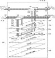
当業者によって理解されるように、図1の中に描かれる例示的な航空機10は、実質的に複合材の材料又は複合材から作られる機体を含む。航空機10の機体の上の外側の複合材の外板は、機体のフレームの曲線に従う。機体は、前方のセクション12、中間のセクション14、及び後方のセクション16を含む。セクション区切り18、20、22は、隣接する航空機のセクションの間で画定される。複合材の航空機10は、任意の数のエンジンを有する。図1の中において示されるように、左側のエンジン30は左側の翼の上で支持され、かつ右側のエンジン32は右側の翼の上で支持される。エンジン30、32の各々は、エンジン30、32の間の機体及び航空機システムに対する損傷が、エンジン30、32のうちの1つに関わる場合又は動作不良の結果として生じる、動翼破裂区域38(図5A)を画定する動翼を有している。
As will be appreciated by those skilled in the art, the
複合材の航空機10は、任意の数のセクションを有し、かつ複合材の航空機10の範囲内の航空機のセクション又はシステムの位置は、時々、動翼破裂区域38の前方又は後方として説明される。フロアビームの上の乗客用のコンパートメント及びフロアビームの下の積荷を保持するための積荷領域を画定するために、フロアビームが機体のフレームの間で延伸する。機体のフレーム及びフロアの間で延伸する支柱は、複合材の航空機10のフロアを強化することにおいて助力となる支えを提供する。乗客用の領域は圧力が加えられ、かつ積荷領域の全て又は部分も圧力が加えられる。機体のフレーム及び支柱の間などの、乗客用のコンパートメントの上又は積荷領域の中のフロアの下の、複合材の航空機10のクラウンラン(crown run)を通してダクトが位置決めされる。
The
エンジン30、32の各々の上にあるのは、高い電圧のAC左側発電機34a、34b及び高い電圧のAC右側発電機36a、36bなどの1以上の主要な1次電源である(以後、集団的に及び/又は一般的に「左側発電機34」、「右側発電機36」、又は「発電機34、36」として言及される)。1次給電線40a及び40bは左側発電機34a、34bから延伸し、かつ1次給電線42a及び42bは右側発電機36a、36bから延伸する。図1の中において示されるように、1次電力は、1次給電線40a、40b、42a、42b(以後、集団的に及び/又は一般的に「給電線40、42」として言及される)を介して、複合材の航空機10の中全体を通して分散される。複合材の航空機10はまた、エンジン30、32が動かなくなった場合に電力を供給するためと同様に、発電機34、36のうちの1以上が故障した場合における冗長性のために、1以上の高い電圧の補助電源ユニットの発電機54を有している。複合材の航空機10が停止し、かつエンジンが動いていない場合、電力は、高い電圧のAC外部電源ユニット56などの1以上の電源によって航空機に提供される。
Above each of the
本開示の目的のために、低い電圧及び高い電圧は、航空機業界の範囲内において、かつ航空無線技術委員会組織によって出版されたアビオニクスハードウェアの環境テストのための標準である、機上装備のための環境条件及び試験手順の、DO−160の中において説明されているように、典型的には低い又は高い電圧のいずれかとして言及される。この開示を通して、230VACは高い電圧として言及されるが、230VACよりも高い又は低い電圧の領域の範囲内の別の電圧もまた高い電圧として言及され得る。また、28VDC及び115VDCは低い電圧として言及されるが、28VDC及び115VDCのいずれかよりも高い又は低い電圧の領域の範囲内の別の電圧もまた低い電圧として言及され得る。 For the purposes of this disclosure, low and high voltages are used in on-board equipment, a standard for environmental testing of avionics hardware within the aviation industry and published by the Aviation Radio Technical Committee organization. As described in DO-160, environmental conditions and test procedures for typically referred to as either low or high voltage. Throughout this disclosure, 230 VAC is referred to as a high voltage, but other voltages within the region of higher or lower voltage than 230 VAC may also be referred to as higher voltages. Also, 28 VDC and 115 VDC are referred to as low voltages, but other voltages within the region of higher or lower voltage than either 28 VDC and 115 VDC may also be referred to as lower voltages.
図1の中における複合材の航空機10は、電力装置及び通信装置を収納するための専用の集中型の装置ベイを有していない。装置は、MECsとして言及され、複合材の航空機10の全体を通して空間的に分散される、モジュール式の電力及び通信装置センターの中へと構成される。例えば、1以上のMECsは、前方、中間、及び後方のセクション12、14、16の各々の中に、空間的に分散される。MECsの各々は、局所的な電力変換を提供し、かつ以下に詳細に説明されるように、1次MEC44、2次MEC46、又は補助の若しくは予備のMEC48のいずれかであり得る。1次MEC44、2次MEC46、及び予備のMEC48は、概して、1以上の適用可能な参照番号44、46、48を伴う「MEC」として言及される。1次電力は、給電線40、42を介して、セクション区切り18、20、22を横断して、発電機34、36からMECs44、46、48の各々の1次電力入力へ分散される。
The
最適化されたフォールトトレランスのために、航空機10は、航空機10の後部に位置決めされる予備のMEC48、及び航空機10の前方、中間、及び後方のセクション12、14、16の各々の中に位置決めされる少なくとも2つのMECs44、46を含む。例えば、図1の中で、冗長性は、セクション区切り18、20、22を横断する必要なしに、各々の航空機のセクションの中に、複数のMECs44、46、48を有することによって取得される。好ましくは、各々のセクション12、14、16は、1次MEC44及び対応する2次MEC46を含み、それによって、MECs44、46のツーバイスリー(a two by three)プラス予備のMEC48の構成を画定する。その次に、4つの別々の航空機のセクションが存在する場合、MECs44、46のツーバイフォー(a two by four)の構成が存在する。好ましくは、MECs44、46、48は、航空機10の長さに沿って互いに関して左側及び右側に交互に置かれる。本開示は、MECs44、46、48の任意の特定の数又は構成に限定されるものではない、ということが理解されるべきである。
For optimized fault tolerance, the
装置負荷50は、ディスプレー、ファン、環境ユニット、及び同様なものを含む航空機の中の様々な電気負荷であるが、それらに限定されるものではない。時々、装置負荷50は、ライン交換ユニット(LRU)52の形をとる(図4)。航空機のセクション12、14、16の各々の範囲内の装置負荷50は、電力及び通信の1以上の区域の中へグループ化される。複数のシステムにわたる装置負荷50の各々の区域は、一番近いMEC44、46と関連し、かつそれによって担われる。好ましくは、装置負荷50の各々の区域は、単一のセクションの範囲内に置かれ、かつその同じ区域の中の少なくとも1つのMECと関連する。好ましくは、接続ワイヤー又はラインは、セクション区切り18、20、22を横断しない。
The
概して、航空機10の上の任意の装置負荷50は、電力及び通信データの両方を必要とする。データは、装置負荷50に何をすべきか伝え、又はその現状についてフィードバックを提供するために必要であり、一方、電力は、装置負荷50がその意図された機能を実行できるようにするために必要とされる。電力及びデータが異なる装置センターから装置負荷50へ提供される場合、かつ電力又はデータのいずれか1つが失われる場合、その後、装置負荷50は、決定できない状態をその次に有する。決定できない状態を避けるために、各々のMEC44、46、48は、独立して、関連する区域の範囲内において局所的な装置負荷50の各々を担うために、電力及び通信データの両方を提供する。装置負荷50に対する電力及びデータ通信は、一番近いMEC44、46、48などの単一の電源から、装置負荷50に対して提供される電力及びデータ通信の両方が発生するので、一緒に同期され又はグループ化されることができる。同期された電力及び通信データは、時々、電力チャネルとして言及される。区域の範囲内の装置負荷50の各々は、特定のMEC44、46から電力を受信し、かつそれ故、それらの同じ装置負荷50に対してデータを提供するネットワーク通信スイッチは、同じMEC44、46によって電力供給される。
In general, any
MECs44、46、48は、主要な電源から受信した電力を分散するように構成される。MECs44、46、48は、独立して、1次電力を2次電力に変換する。2次電力はMECs44、46、48から分散され、その後独立して、2次ブランチ電力ネットワークがセクション区切り18、20、22を横断して延伸することなしに、各々の区域の範囲内において装置負荷50の各々を担う。そのような場合において、1次電力の制御及び変換は、1次電力のみがセクション区切り18、20、22を横断して1次MECsの間で分散されるように、航空機10の各々のセクションの1次MECs44の各々に分散される。好ましい構成において、高い電圧の給電線及びデータの基幹回線のみが生産ライン停止を回避できる。
The
1次電力のみをセクション区切り18、20、22を横断して分散することは、航空機の10の複数のセクションを横断して2次電力を分散するために必要とされるワイヤーの量を低減する。これは、分散されたMECのアーキテクチャが、2次配線のより短い長さを許容する各々のセクションの範囲内で別々の2次電力分散ネットワークを生成するからである。そのようにすることは、隣接する機体のセクションを繋ぐ場合に必要とされる2次接続の数と同様に、航空機全体を通して利用されるワイヤーの全体の重量を低減する。また、より短い2次電力の長さのために、電流リターンネットワークの範囲内の実装と比較して、給電線の長さの全ループ領域が低減される。さらに、航空機の生産工程は、セクション区切りを横断して延伸するワイヤーの2次電力ネットワークが限定され又は消去されるために、改善される。セクション区切りを横断して延伸する2次電力ワイヤーの低減は、航空機10の最終的な組み立ての前における他のセクションへの依存が低減されるため、より素早く試験され、かつより早く製造品質が確認される。
Distributing only primary power across section breaks 18, 20, 22 reduces the amount of wire required to distribute secondary power across multiple sections of the aircraft . This is because the distributed MEC architecture creates a separate secondary power distribution network within each section that allows for shorter lengths of secondary wiring. Doing so reduces the overall weight of the wire utilized throughout the aircraft, as well as the number of secondary connections required when connecting adjacent airframe sections. Also, because of the shorter secondary power length, the total loop area of the feeder line length is reduced compared to implementations within the current return network. In addition, the aircraft production process is improved because the secondary power network of wires extending across the section breaks is limited or eliminated. The reduction in secondary power wires that extend across the section breaks is tested more quickly and confirms manufacturing quality faster because it reduces reliance on other sections prior to final assembly of the
図1の中において示されるように、1次給電線40aは、左側のエンジン30の上の発電機34bから延伸して中間のセクション14へ進み、中間のセクション14の左側の上に示されるMEC44に至り、セクション区切り20を横断して前方のセクション12の左側の上に示される別のMEC44に至り、かつその後、前方のセクション12の前の左側の上に示される別のMEC44に至る。1次給電線40bは、左側のエンジン30の上の発電機34aから延伸して中間のセクション14へ進み、左の上のMEC44に至り、セクション区切り22を横断して左後方のMEC44に至り、かつその後、左後方のMEC48に至る。給電線42aは、右側のエンジン32の上の発電機36aから延伸して中間のセクション14へ進み、セクション区切り20を横断して前方のセクション12の右側の上のMEC44に至り、かつその後、前方のセクション12の前の右側の上の別のMEC44に至る。1次給電線42bは、右側のエンジン32の上の発電機36bから延伸して中間のセクション14へ進み、中間の右側のMEC44に至り、セクション区切り22を横断して右後方のMEC44に至り、かつその後、右後方のMEC44に至る。代替的に、給電線40a、40bは、代わりに、航空機10の1以上のセクションの右側の上のMECs44に1次電力を提供してもよい。そのような場合において、給電線42a、42bは、航空機10の1以上のセクションの左側の上のMECs44に1次電力を提供する。
As shown in FIG. 1, the
また、左側のエンジン30の上の発電機34a、34bのうちの一方は、動翼破裂区域38の前方の航空機の一方の側に1次電力を提供することができ、かつ左側のエンジン30の上の発電機34a、34bのうちの他方は、動翼破裂区域38の後方の航空機10の他方の側に1次電力を提供することができる。そのような場合、右側のエンジン32の上の発電機36a、36bのうちの一方は、動翼破裂区域38の前方の、左側の発電機34a、34bのうちの一方によって電力を送られるのと反対側に、1次電力を提供することができる。右側のエンジン32の上の発電機36a、36bのうちの他方は、動翼破裂区域38の後方の、左側の発電機34a、34bのうちの他方によって電力を送られるのと反対側に、1次電力を提供することができる。
Also, one of the
図2は、エンジン30、32に運用問題がある場合に1次電力の利用可能性を増加させる、航空機10の動翼破裂領域38に関するエンジン毎の2つの発電機の分割を図解している。エンジン30、32のうちの一方が失われる場合、又はエンジン30、32のうちの一方の範囲内の発電機34、36の一方が故障した場合、残っているエンジンン30、32の上の2つの残っている発電機34a、34b、36a、36bは、航空機10に対して前方及び後方の両方の1次電力を分散する。左側のエンジン30の発電機34a及び右側のエンジン32の発電機36aは、前方のタイバス76によって互いに接続される、動翼破裂区域38の前方の1次電力スイッチングバス96aのペアに電力を供給する。左側のエンジン30の発電機34b及び右側のエンジン32の発電機36bは、後方のタイバス78によって接続される、動翼破裂区域38の後方の1次電力スイッチングバス96aの別のペアに電力を供給する。中間のタイバス80は、前方の1次スイッチングバス96aのうちの少なくとも1つを、後方1次スイッチングバス96aのうちの少なくとも1つに接続する。それ故、エンジン30、32が作動上の不具合を経験する場合、航空機10は、前方及び後方のやり方において、残っているエンジン30、32から電力の分散を受けるため、航空機10の全体の長さに沿って一方の側の上で電力を得てかつ制御を行うことを継続する。電力及び制御は、配線の量を増やすことなく、動翼破裂区域38の前方及び後方の両方において、単一のエンジン30、32から分散される。図2はまた、以下に詳細に説明されるように、電力の変換及び装置負荷50に対する分散のために2次MECs46に電力を分散する、1次電力スイッチングバス96aを図解している。予備のMEC48は、以下により詳細に説明されるように、1次主要AC電源が1次電力スイッチングバス96aに対して利用可能でない場合、バックアップ電力を提供する2次MECs46に結合される。
FIG. 2 illustrates the split of two generators per engine for the blade burst
1以上の区域の中において担われていない装置負荷50が、先ず2つの理由で生ずる。発電機34、36の全てが故障し、かつそれ故、任意のMECs44、46に対して1次電力がもはや利用可能ではないか、バス96の1以上が動翼又はタイヤの破裂などの場合のために物理的に損傷を受ける場合のいずれかである。1以上の主要な1次電源の故障に基づく、4つの発電機34、36又は補助電源ユニットの発電機54のいずれかからの高い電圧の電力の経路再選択は、図3の中において描かれている1次電力バスネットワークシステム90によって示されるように、スイッチのオープン及びクローズの組み合わせを通して、タイバス76、78、80を介して1次バスレベルにおいて行われる。1以上の実施形態において、1以上の独立型の半導体スイッチ、例えば接触器が、1次電力スイッチネットワークシステム90の上に含まれる。半導体スイッチは各々、1以上の局所的な保護、電圧感知、及び電流感知を提供するように構成される自己完結型の制御機能を有し、それらは、他の電力システムの構成要素から独立している。独立型の半導体スイッチは、他の電力システムの構成要素からのデータを必要とすることなしに、機能することができる。半導体スイッチのオープン及びクローズは、MECs44、46、48の1以上に対して1次電力スイッチングバスの1以上を横断する1次電力を遮断しかつ送る。図3から始まり、特定の接触器が、先ずクローズしているか又は先ずオープンしているかのいずれかとして描かれている。オープンしている接触器の記号は、2つの平行線である。通常クローズしている接触器の記号は、平行線に斜線が引かれていることのみを例外として、同じである。独立型の半導体スイッチはまた、独立型の半導体スイッチを通る電流を制限する、パルス幅変調を含む。高い電圧のバス及び変換の故障に基づくMECs44、46、48の間の2次電力及び低い電圧DCの経路再選択は、図3の中において描かれる1次電力バスネットワーク90によって示されるように、スイッチのオープン及びクローズの組み合わせによって行われる。
A
各々のMEC44、46、48は、1次及び予備の両方の電力を有しており、かつ中央のコンピュータシステムの上に依存することなしに、閉回路処理及びセンサの局所的な制御を独立して実行することができる。分散された電力システムの制御アーキテクチャは、MECs44、46、48の間でビークル全体の電力分散状態を分かち合うことを許容するが、各々のMEC44、46、48は、また予備の電力を全ての他のMECs44、46に分散するMEC48を例外として、各々のMECの近傍において装置負荷50を担うことに責任を有するのみである。各々のMEC44、46、48は、各々のMEC44、46、48が独立して装置負荷50のそれ自身の区域の範囲内においてオペレーションを実行するように、一番近い装置負荷50の区域と関連するデータを管理する。
Each
各々のMEC44、46、48はまた、好ましくは、バス電力制御のための半導体スイッチングを有し、かつまた回路保護を提供する。図3において、発電機34、36に接続されている1次給電線40、42からの電力は、1次電力スイッチングバス96aに電圧を加える。各々の1次電力スイッチングバス96aは、MEC44の範囲内の1次電力スイッチングバス96b、及びMEC46の範囲内の1次電力スイッチングバス96cに枝を伸ばすように繋がる。分散フィード98を伴って1次電力スイッチングバス96bに接続された各々の1次電力スイッチングバス96aは、図4の中において示されるようにかつ以下により詳細に説明されるように、単一の1次MEC44に対応する。
Each
図4を参照すると、1次電力スイッチングバス96aを伴う各々の1次MEC44の一部分は高い電力の部分120であり、かつ1次電力スイッチングバス96bを伴う1次MEC44の別の部分は1次MEC44の低い電力の部分122である。1次MEC44の高い電力の部分120は、航空機10に対して利用可能な任意の高い電力の主要な電源から1次電力を受信するように構成され、かつ時々、1次電力スイッチングネットワーク装置302として言及される(図12Aから図12C)。航空機10の範囲内の1次MECs44の高い電力の部分120のネットワークは、高い電圧の1次電力スイッチングネットワークを画定する。
Referring to FIG. 4, a portion of each
低い電力の部分122は、好ましくは、搭載された電源からの電力の一部分を扱うように構成されるが、未だ高い電力の部分120と同じ電圧を扱うことができるのみである。1次電力スイッチングバス96cは、図4の中において示される2次MECs46に対応する。図4はまた、2次MEC46及び1次MEC44の低い電圧の部分122の間の類似性を最も良く示している。1次MECs44は、2次MECs46が有していない航空機10にわたる1次電源の経路再選択を行うために、1次電力スイッチングバス96aの1次レベルの電力ネットワークバス構造を含む。異常なオペレーションと同様に正常なオペレーションの間に、1次及び2次MECs44、46の両方は、1次及び予備の電力を有している。2次MECs46は、1次MEC44とちょうど同じように、一番近い装置負荷50を担う。
The
再び図3を参照すると、分散フィード98は、各々の1次MEC44の1次電力スイッチングバス96a及び96bの間を延伸し、かつ分散フィード100は、1次MEC44の各々のバス96b、及び同じ電源から直接に電力を受信する2次MEC46の1次電力スイッチングバス96cの間を延伸する。また、クロスタイ102は、左側の発電機34aと関連する1次MEC44の1次電力スイッチングバス96b、及び右側の発電機36aと関連する1次MEC44の1次電力スイッチングバス96bの間を延伸する。クロスタイ104は、左側の発電機34aと関連する2次MEC46の1次電力スイッチングバス96c、及び右側の発電機36aと関連する2次MEC48の1次電力スイッチングバス96cの間を延伸する。クロスタイ106は、左側の発電機34bと関連する1次MEC44の1次電力スイッチングバス96b、及び右側の発電機36bと関連する1次MEC44の1次電力スイッチングバス96bの間を延伸する。クロスタイ108は、発電機34bと関連する2次MEC46の1次電力スイッチングバス96b、及び右側の発電機36bと関連する2次MEC46の1次電力スイッチングバス96bの間を延伸する。補助電源ユニットの発電機54は、クロスタイ102、106にそれぞれ接続される。
Referring again to FIG. 3, a distributed
図5Aは、航空機10の範囲内の1次、2次、及び予備のMECs44、46、48の組み合わされた1次及び2次電力分散ネットワークのフォールトトレラントの一構成を示している。より詳細に図解する目的で、図5Bから図5Eは、図5Aの中において描かれる完成したシステムを組み立てるために、互いに隣に位置決めされることができる、4つの分離した部分のクローズアップされた部分図を示している。図5Bから図5Eの各々の上の2つの鎖線は、各々の部分図のブロークンエッジを示している。図5Bは、図5Aの最上部左側の部分を示している。図5Cは、図5Aの最上部右側の部分を示している。図5Dは、図5Aの最下部左側の部分を示しており、かつ図5Eは、図5Aの最下部右側の部分を示している。また、図5Fは、図5Aのシステムの予備のMEC48の一構成を示している。図3の中において示される接触器はまた、図5Aから図5Fの中において象徴的に示されているが、図5Aから図5Fを単純化するために参照番号がなく、かつ他の図面においてもまた任意の参照番号がなく又は別の参照番号を有している。
FIG. 5A shows one fault tolerant configuration of a combined primary and secondary power distribution network of primary, secondary, and spare
図5Aにおいて、1次及び2次MECs44、46は、航空機10の前方のセクションの中に全部で4つ、かつ航空機10の後方のセクションの中に別の4つが存在するようなやり方において、配置されている。好ましくは、前方のセクションのペアの各々の中に1次MEC44及び2次MEC46、かつ後方のセクションのペアの各々の中に1次MEC44及び2次MEC46が存在する。図5Aはまた、航空機10の後方のセクションの中の予備のMEC48を示している。予備のMEC48のための時間制限のない電源は、ラムエアタービン(RAT)128、又はバッテリ若しくは燃料電池などの他の適切な独立した時間制限のある予備の電源であり得る。全ての発電機34、36に関する作動上の不具合が生じた場合、RAT128は、発電機34a、34b、36a、36bの全てが作動上の不具合を有する場合にMECs44、46の1以上に対してするのと同様に、予備のMEC48に対して予備の電力を提供するように展開される。バッテリ598は、時間制限のないRAT128が展開されている一方で、MECs44、46の1以上に対してするのと同様に、予備のMEC48に対して作動のための一時的な電力を提供する。
In FIG. 5A, the primary and
発電機34a、34b、36a、36bのうちの1つが故障した場合、電力は1次MEC46の1次電力スイッチングバス96aにおいて受信されていない。それ故、電力供給されていない1次MEC44の1次電力スイッチングバス96bのより低い電力の部分122から装置負荷50は担われておらず、かつ電力供給されていない隣接する2次MEC46の1次電力スイッチングバス96cから装置負荷50は担われていない。 その後、電力は1次レベルにおいて、その装置負荷50に電力を供給するために電力が供給されていない1次MEC44の1次電力スイッチングバス96aに電圧を加えるために、かつその装置負荷50に電力を供給するために任意の電力が供給されていない隣接する2次MEC46の1次電力スイッチングバス96cに電圧を加えるために、接触器の組み合わせのオープン及びクローズによって他の残っている作動上の電源のうちの1つから新しい経路で送られる。
If one of the
代替的に、MEC44、46、48が物理的な故障を経験しかつ結果としてその装置負荷50に電力が供給されない場合、その後、電力は、別の電力供給されているMEC44、46、48によって電力が供給されていないMEC44、46、48の装置負荷50に電力を供給するように、新しい経路で送られる。新しい経路で送られる利用可能な電力の量に応じて、臨界負荷のみなどの装置負荷50の全部又は一部分のみが再度電力供給される。また、全ての電源が失われかつMECs44、46、48に電力が供給されていない場合、その後、燃料電池又はRAT128を有する予備のMEC48が、他のMECs44、46の臨界装置負荷50に電力を供給することができる。臨界負荷は、航空機10が継続される安全な飛行及び着地を維持するために電力を供給しなければならなかったそれらの装置負荷50である。本質的な負荷は、航空機10を飛行させるために作動が必要とされないラジオ及び他の通信装置などを有することが望ましいそれらの装置負荷50である。本質的でない負荷は、調理装置、装飾的な照明、及び客室用娯楽システムを含む乗客の快適性に関わる負荷などの、優先度が一番低い装置負荷50である。
Alternatively, if the
例として、補助電源ユニットの発電機54は、主要な発電機34、36のうちの1つの故障のために失われた装置負荷50を担うことができる。その後、発電機34bが故障した場合、前方のタイバス76、後方のタイバス78、中間のタイバス80における接触器の組み合わせを通して、1次電力が残っている主要な発電機34、36から直接に提供される。代替的に、1次電力は、別の作動しているMEC44、46を通して補助電源ユニットの発電機54からクロスタイ102、104、106、108の1以上を横断して、電力が供給されていない1次MEC44の1次電力スイッチングバス96a、又は電力が供給されていない2次MEC46の1次電力スイッチングバス96cへ提供される。
By way of example, the auxiliary
MECs44、46のうちの1以上が物理的な作動上の不具合を有する場合において、各々の作動上の不具合を有するMEC44、46と関連する区域の範囲内の複数の装置負荷50の全て又は部分は、近傍において一番近い1以上の他のMECs44、46と関連することができる。例えば、1次MEC44が物理的に故障した場合、その故障したMEC44に一旦、担われていた装置負荷50は、別のMEC44、46又はMECs44、46の組み合わせによって担われることができる。MECs44、46は、故障したMEC44によって一旦、担われていた装置負荷50の種類を判定することができ、その後、MECs44、46の組み合わせの1以上がそれらの電力を供給されていない装置負荷50を担うべきか否かを判定する。故障した1次MEC44の一番近い近傍の中にある2次MEC46が付加的な装置負荷50を担うべきと判定された場合、その後、その2次MEC46と元々関連する区域は、故障した1次MEC44によって以前、担われていた区域を包含するように拡大される。
In the case where one or more of the
代替的に、付加的な装置負荷50は、故障した1次MEC44の近傍の中にある2次MEC46及び別の1次MEC44の間で分割される。そのような場合、一番近くで作動している1次MEC44と関連する装置負荷50の区域は、故障した1次MEC44によって以前、担われていた区域の一部分を含むように拡大され、かつ一番近くで作動している2次MEC46と関連する装置負荷50の区域は、故障した1次MEC44によって以前、担われていた区域の残っている部分を含むように拡大される。いずれの場合においても、故障したMEC44、46の近傍の中にある1以上の他のMECs44、46は、故障したMEC44、46によって以前、担われていた装置負荷50に対して独立してサービスを提供するように、電力供給させられる。
Alternatively, the
各々の2次MEC46及び各々の1次MEC44の各々の低い電力の部分122は、変換装置に結合される接触器を含む。変換装置は、変圧整流器ユニット(TRU)134を含み、それは、230VACを整流し、かつそれをバス136のための28VDCなどの主要なDC出力に変換し、かつ230VACを低い電力のAC出力バス140のための115VACに変換するための単巻変圧器又は自動ステップダウン変換ユニット(ATU)138を含む。各々の2次MEC44及び1次MEC44の低い電力の部分122はさらに、冗長性のためだけにではなく、継続される安全な飛行及び着地のために絶対的に必要な臨界負荷に対してのみ電力を提供するための、第2のTRU142を含む。第2のTRU142を臨界負荷に対してのみ限定することは、予備の電源が負荷過剰になっていないことを確実にする。
Each
図6は、例えば前方のセクション12における、2次電力バス構成を図解し、ここで、1次MECs44の低い電力の部分122の中の1次電力スイッチングバス96b、及び2次MECs46の1次電力スイッチングバス96cは、一緒に結び付けられる。上述されたように、損傷を受けたMEC44、46の電力供給されていない装置負荷50の全て又は一部分のみが別のMEC44、46によって担われるか否かは、利用可能な電力に応じる。航空機のセクションの範囲内のMECs44、46のうちの1つの中のTRUs134のうちの1つが故障した場合、作動上の不具合を起こしたTRU134からの最も臨界的な装置負荷50は、同じ航空機のセクションが様々な接触器及びバックアップバス148を横断する2次電力を提供するように、別のMEC44、46によって担われる。
FIG. 6 illustrates a secondary power bus configuration, for example in the
好ましくは、後方のセクション16の中のMECs44、46は、給電線のワイヤーの重量を最小化する互いに対するそれらの近接のために、補助電源ユニットの発電機54からの2次電力関係を有している。また、航空機10の前方のセクション12の中のMECs44、46は、図2及び図6の中において示されるように、外部電源ユニット56などの外部電力の地上サービス装置からの115VACなどのより低い電圧のレベルにおいて連結される。しかしながら、地上から前方のセクション12の中のMECs48の中の低い電力のAC出力バスへの115VACは、その後、航空機10の他のセクションの中の他のMECs44、46へ分散される、双方向のATUs138によって230VACなどのより高い電圧へ変換されることができる。また、典型的に、第2のTRU142は、上述されたようなより臨界的な負荷に対して使用され、失われたそれらの臨界負荷に電力を供給するために、バックアップバス148を介して、バッテリバス294からのバッテリ電力を利用可能にする。
Preferably, the
図7の中において示されるように、各々のMEC44、46、48の内側に置かれる、(ハードウェア及びソフトウェアを備える)コンピューティング及びネットワークインターフェース(CNI)モジュール162は、分散コンピューティング機能及び双方向データのゲートウェイルーティングを提供する。各々のCNIモジュール162は、フォールトトレラントコンピューティングシステムになる、2つのフェールセーフコンピューティングシステムを含む。各々のフェールセーフコンピューティングシステムは、他のものに対して冗長である。このフォールトトレラントコンピューティングシステムは、航空機10の範囲内のシステム機能に対するサービスが欠乏しないことを可能にするために、予期されぬハードウェア及び/又はソフトウェアの故障に率直に反応する。CNIモジュール162は、(フレックスレイ(Flex Ray)、コントローラエリアネットワーク(CAN)、エアリンク(ARINC)664、ティーティーピー(TTP)、又は他のバステクノロジー)などの内部システム通信バスを介して、内部MECコンピューティング機能及び外部MECコンピューティング機能に対して/から、データを送信/受信する。航空機10の上の他のMECs44、46、48は、それぞれ参照番号188及び190を有する、図7の中で示される外部データ通信チャネルA及び外部データ通信チャネルBを横断する、ARINC664などのデータネットワーク指定を介して、CNIモジュール162と通信することになる。
As shown in FIG. 7, the computing and network interface (CNI) module 162 (with hardware and software), located inside each
CNIモジュール162は、航空機10のその局所的な区域の範囲内で使用される、特定のソフトウェアアプリケーションをホストする分散コンピューティング要素である。CNIモジュール162の上でホストされることができるシステムアプリケーションのいくつかの実施例は、AC及びDC電力システム、貨物口システム、乗客用の入口ドアシステム、着陸装置システム、及び乗客用の客室システムである。CNIモジュール162に対して通信するコンピューティング機能は、TRUs134、TRUs142、ATUs138、ブレーカーモジュール166の半導体スイッチ、発電機34、36のうちの1つと関連する発電機制御ユニットGCU168、ソリッドステート電力分散モジュール170、及び遠隔データ集線装置である。CNIモジュール162は、以下により詳細に説明されるように、MEC44、46、48の範囲内で、内部データチャネルA202及び内部データチャネルB204を横断して、TRUs134、142、ATUs138、ブレーカーモジュール166、GCU168、及び電力分散モジュール170と内部で通信する。
The
CNIモジュール162は、これらのコンピューティング機能に対して/からデータを送信及び受信することになる。CNIモジュール162はまた、他のMECs44、46、48及び航空機のコンピューティングシステムから現状及び健全性を送信及び受信する。各々のCNIモジュール162は、他のMECs44、46、48の中で何が起きているかを知った上で、個別のMEC44、46、48の作業負荷を管理する。一旦、情報がMEC44、46、48のCNIモジュール162によって受信されてしまうと、そのコンピューティング機能は、どのシステムがデータを必要としているかを判定し、データの健全性を解釈し、任意の電力システムの異常に反応し、それを必要とするコンピューティング機能に対して緊急を要する情報を供給し、システムレベルの論理アルゴリズムを実行し、航空機レベルのシステムの故障を報告し、かつその区域に対するAC及びDC電力の分散を制御することになる。
The
図8は、セクション区切り18、20、22によって分離される空間的に分散されたMECs44、46、48の間の通信バスインターフェースを有するデータネットワーク構造を図解している。この構成は、各々の個別のMEC44、46、48が、故障の全域で継続される通信を確実にするために必要とされる冗長性を提供するのと同様に、他のMECs44、46、48と通信することを可能にする。セクション区切り20は、航空機の前方及び後方のセクションを画定する。必要とされるネットワーク通信スイッチの数は、MECs44、46、48の数及び望ましいフォールトトレランスによって決定される。図8は、ネットワークスイッチ182a‐b、184a‐b、186a‐bの3つのペア(以後、集団的に及び/又は一般的に「ネットワークスイッチ182、184、186」として言及される)を有する9つのMECs44、46、48を示している。各々のネットワークスイッチ182、184、186は、相互作用するMECs44、46、48の各々のCNIモジュール162から2次電力を受信することができる、層‐3ネットワークスイッチなどの多層ネットワークスイッチである。より多くのMECs44、46、48が存在すれば、その後、同じレベルのフォールトトレランスを取得するためにより多くのネットワークスイッチが必要とされる。
FIG. 8 illustrates a data network structure having a communication bus interface between spatially distributed
各々のMEC44、46、48は、A及びBの通信チャネルを有する。 各々の1次MEC44のチャネルA及びBは、別の1次MEC44又は予備のMEC48のいずれかの上の2つの対応するA又はBスイッチと接続する。各々の1次MEC44は、チャネルA又はチャネルBのいずれかの上の1つのネットワークスイッチ182、184、186を含み、一方、航空機の後方のセクションの中の予備のMEC48は、A及びBの両方のチャネルの上のネットワークスイッチ182、184、186のペアの両方のスイッチを含む。スイッチ182a、184a、186aは、チャネルAに対応し、かつスイッチ182b、184b、186bは、チャネルBに対応する。外部通信のデータライン192は、データラインを切り替えるスイッチを示している。
Each
概して、セクション区切り20の一方の側の上の各々の1次MEC44の上のネットワークスイッチは、それらのMECs44、48のうちの少なくとも1つがセクション区切り20の他方の側の上にあり、かつ1つは航空機10の反対側にある、他の1次又は予備のMECs44、48の2つの他のネットワークスイッチに接続される。例えば、セクション区切り20の前方の前方右側1次MEC44のネットワークスイッチ182aは、セクション区切り20の他方の側の上において、後方左側1次MEC44の上のネットワークスイッチ184a、及び予備のMEC48の上のネットワークスイッチ186aの両方に接続される。セクション区切り20の前方の前方左側1次MEC44の上のネットワークスイッチ182bは、セクション区切り20の他方の側の上において、後方右側1次MEC44の上のネットワークスイッチ184b、及び予備のMEC48の上のネットワークスイッチ186bの両方に接続される。予備のMEC48の上のネットワークスイッチ186bはまた、航空機10の反対側の上のネットワークスイッチ184bに接続される。ネットワークスイッチ184aはまた、予備のMEC48のネットワークスイッチ186aに接続される。
Generally, the network switch on each
2次MECs46の各々はまた、2つの他の1次又は予備のMECs44、48を有する2つのデータチャネルを有している。外部通信のデータライン196は、2次MEC44に対する直接的な1次MEC44のネットワークスイッチのデータ接続を示している。各々の2次MEC46のチャネルのうちの一方は、セクション区切り20の他方の側の上の1次MEC44の同じチャネルの上のネットワークスイッチに接続され、かつ他方のチャネルは、別の2次MEC46に接続される。それ故、図8は、セクション区切り20を横断する8つのデータバス接続、及びセクション区切り18、22の各々を横断する4つのデータバス接続を示している。この構成は、航空機の中の配線の全体の重量と同様に、セクション区切りを横断する通信配線の量を最小化する。航空機10のクラウン及びフロアの中の空間を利用することによって、各々のデータバスの間で分離が維持される。健全なCNIモジュール162は、他の健全なCNIモジュール162からの局所的な環境情報及び通信を利用することによって、組織的に調整されたやり方で、電力システムの変化する構成に対して最適に反応することができる。
Each of the
任意の2つのMECs44、46、48に電力が供給される場合、その後、それらの2つのMECs44、46、48が互いに十分に通信できるように、通信ネットワークがアクティブになり、かつデータが提供されることになる。この通信ネットワークは、MECsのペアの間の任意の1つの接続が、MEC44、46、48の機能性が低減されることなしに失われるような、フォールトトレラントのネットワークである。さらに、同時におけるMECs44、46、48の間の最大で任意の2つの通信接続の喪失は、MECs44、46、48のうちのただ1つとのデータ通信の喪失をもたらす。健全なCNIモジュール162は、他の健全なCNIモジュール162からの局所的な環境情報及び通信を利用することによって、組織的に調整されたやり方で、電力システムの変化する構成に対して最適に反応することができる。
If any two
例えば、前方右側の1次MEC44のチャネルAの上のネットワークスイッチ182aの喪失は、前方右側の1次MEC44への及びからの通信がチャネルBを通じて継続されるので、前方右側の1次MEC44への及びからの通信の完全な喪失をもたらさない。チャネルAを介して前方右側1次MEC44と通信してきた任意の他のMECs44、46、48は、チャネルBを通じて、又はチャネルBを介して前方右側1次MEC44に接続される他のMECs44、46、48を介して、直接に通信することができる。また、前方右側1次MEC44のチャネルAの上のネットワークスイッチ182aが、前方右側の2次MEC46に対するチャネルBの接続に加えて失われた場合、前方右側の1次MEC44への及びからの通信はチャネルBを介して継続されるが、その後、通信はチャネルA及びBの両方が失われたので前方右側の2次MEC46のみを伴って失われることになる。
For example, the loss of the
本開示の1つの態様は、分散電力制御アーキテクチャである。電力制御は、電力それ自体と同様に各々のMEC44、46、48に対して分散される。局所的なデータに基づいて、各々の個別のMEC44、46、48は集まって、各々のMEC44、46、48は、任意の他のMECs44、46、48に依存する必要なしに、それ自身の装置負荷50を構成するために、その関連する区域のそれ自身の電力制御を実行する。電力を新しい経路で送ることに対する必要性などの現実に必要とされるデータのみが、他のMECs44、46、48のCNIモジュール162に対して送られる。
One aspect of the present disclosure is a distributed power control architecture. Power control is distributed to each
地上の航空機10の通常のパワーアップは、好ましくは、MECs44、46、48の順次的なパワーアップである。通常のパワーアップは、静止インバーター290及びバックアップバス148を介して、MECs44、46の中の全ての予備のバスに電力を供給するバッテリ598を介して、行われる。バッテリ598が利用可能でない場合、外部電源ユニット56からの外部電力の限られた量は、先ず予備のMEC48に電力を供給するために送られる。一旦、予備のMEC48がパワーアップされると、その後、電力は予備のMEC48から他の1次及び2次MECs44、46の各々に対して分散され、利用可能な電源を有しているのと同様に適切に、各々のMEC44、46の範囲内において、それらのCNIモジュール162をパワーアップし、かつ接触器を構成する。一方、MEC44、46が通常の飛行のオペレーションの間に電力供給を受けられなくなる場合、順次的なパワーアップは利用されない。MECs44、46のうちの一方の中のCNIモジュール162が1次電力を有していない場合、分散フィード100を有する1次MEC44及び2次MEC44などの、2つのMECs44、46の間の低い電力の相互接続は、上述されたように電力が供給されてないMEC44、46に今もなお電力を供給する手段を提供する。
The normal power up of the
CNIモジュール162は、他のMECs44、46、48からの構成データと同様に、他のシステム又はLRUsからの入力/出力通信を読み込む。各々のMEC44、46、48の構成データを送信することは、他のMECs44、46、48の各々が、航空機10の中の他の場所で何が起きているかを判定することを可能にする。その後、CNIモジュール162は、そのMEC44、46、48の範囲内でブレーカー及び接触器を構成するためにこのデータを使用し、かつそれから、他のMECs44、46、48が同じことをできるように、他のMECs44、46、48に送信するために、その区域の範囲内の装置負荷50についてチャネルA又はBの上へ構成データを書き込む。各々のCNIモジュール162は、通信の入力/出力及びそれが受信する環境データの有効性をチェックし、かつ必要な場合はそれ自身の環境データ及びそのブレーカーの現状を判定するために、それを改良する。一旦、CNIモジュール162がその区域の範囲内のそのブレーカー及び接触器にどのようにして命令したいかを理解すると、その後、それは、その構成データを外の他のMECs44、46、48へ送る。
The
各々のMEC44、46、48のCNIモジュール162は、そのMEC44、46、48に対して割り当てられた境界の範囲内の装置負荷50を制御するのみである。特定のMEC44、46、48の各々のCNIモジュール162は、他のMECs44、46、48の装置負荷50構成又はそれらのブレーカー若しくは接触器をどのようにして構成するかを設定しない。しかしながら、全てのMECs44、46、48は今でも、航空機10の1次及び2次電力システムのために一貫して統一された電力移送機能を提供するために、互いに相互作用する。正しく機能しているMECs44、46、48のCNIモジュール162は、作動上の問題を有しているMEC44、46、48に対して反応し、かつ電力タイバス76、78、80、分散フィード98、100、及びクロスタイ102、104、106、108を横断する電力の経路再選択を、付加的な故障を伴う場合であってもすることができる。コンピューティング及びネットワーキングのアーキテクチャは、フェールセイフ及びフォールトトレラントの両方を有している。CNIモジュール162が作動上の問題を有している場合、その接続された負荷の全ては、所定のデフォルト「フェールセイフ」状態に入る。隣接するCNIモジュール162は、それらの区域の外側の他の装置負荷を制御する容量及び正統性を有していない。
Each
図9の中において示されているCNIモジュール162は、CNIモジュール162の一方の側の上でチャネルAに対応する1つのネットワークスイッチ182、184、186、及び他方の側の上でチャネルBと対応する別のネットワークスイッチ182、184、186を含む。両方のネットワークスイッチ182、184、186は、外部データ通信接続を実現するための1以上のポート206を有している。CNIモジュール162の各々の側はまた、以下により詳細に説明されるように、MEC44、46、48の範囲内の内部データ通信接続を実現するための1以上のポート208を有している。CNIモジュール162は、チャネルA及びチャネルBのデータ通信を処理することに関連する複数の指示を行うための2つのマルチコアプロセッサ242、244を含む。各々のプロセッサ242、244は、ポート208においてMEC44、46、48の範囲内において通信データを受信及び送信するための、又はポート206を通じていずれかのネットワークスイッチ182、184、186を伴ってMEC44、46、48の外側の通信データを受信及び送信するための指示を処理することができる。CNIモジュール162の一方の側の上のプロセッサ242、244のうちの一方は一方の通信チャネルと対応し、かつCNIモジュール162の他方の側の上の他方のプロセッサ244は他方の通信チャネルと対応する。しかしながら、各々のプロセッサ242、244は、各々のプロセッサ242、244が両方のチャネルA及びBの通信を読み込んで処理することができるように、他方の通信チャネルのための他のネットワークスイッチ182、184、186に対する重なり部分を有する。
The
CNIモジュール162などのMEC44、46、48のトラスシステムの上に置かれる各々の構成要素又はLRU52は、光学的にラベルを読み込むためのバーコードリーダ248を含む。バーコードリーダ248は、QRコード(登録商標)を読み込むための素早い反応の(QR)コードリーダである。(図示されぬ)バーコードは、MEC44、46、48の中、又はバーコードリーダ248の近傍における航空機10の中の他の場所に置かれる。バーコードを読み込むバーコードリーダ248は、MEC44、46、48が、MEC44、46、48のCNIモジュール162のソフトウェアのパラメータを設定するために、自他識別、位置、時間追跡、及び他の構成情報などの情報を入力することを可能にする。例えば、バーコードリーダ248は、MEC44、46、48がそれが航空機10のどのセクション又はどちらの側に置かれているのかを知るように、CNIモジュール162の位置を読み込む。また、CNIモジュール162の位置を決定することは、MEC44、46、48が一番近い装置負荷50を決定することを可能にする。構成情報はまた、他のMECs44、46、48、航空機10の中の他の場所、又はメンテナンス施設などの航空機10の外側の中心施設に送信される。
Each component or
どれだけの電力がMEC44、46、48から分散されるかに基づいて、CNIモジュール162は、以下に説明されるようなトラスシステムの1以上の転送層から、28VDC又は115VACなどの1以上の付加的な電力入力288、及び電源レギュレーター238を必要とする。例えば、28VDCは、バーコードリーダ248のためのレギュレーター280のユースポイントに対する入力である。各々のCNIモジュール162はまた、ネットワークスイッチ182、184、186の1つ又は両方に電力を供給するために、1以上の他のMECs44、46、48のCNIモジュール162の電力出力286から1以上のDC電力入力284を受信する。電力入力284及び電力レギュレーター246は、単一の電力故障が、任意の処理又は通信チャネルの故障をもたらすことを妨げる、冗長性を提供する。
Based on how much power is distributed from the
入力288においてトラスシステムの転送層からMEC44、46、48への電力の完全な喪失が存在する場合、その後、CNIモジュール162を有するMEC44、46、48、ネットワークスイッチ182、184、186、電力レギュレーター246、及びバーコードリーダ248は、今でも電力供給されている。他のMECs44、46、48の他のCNIモジュール162の冗長電力出力286から送られた1以上のDC電力入力284のために、電力供給されていないMEC44、46、48のCNIモジュールは、決して電力を失わず、かつ隣接するMECから電力を新しい経路で送り、その後、それ自身のMEC44、46、48の1以上の転送層をパワーアップすることができる。その後、MEC44、46、48は今でも、その装置負荷50の一部又は全部を担うことができ、かつCNIモジュール162は十分に機能的であり他のCNIモジュール162と通信することができ、それによって、MEC44、46、48のトラスシステム及び通信ネットワークをアクティブに保つ。
If there is a complete loss of power from the truss system transfer layer to the
図10Aから図10Dは、図5Aから図5Eの中において示される1次MECs44の各々の高い電圧の1次電力スイッチングバス構造の異なる構成を示している。各々は、どの発電機34a、34b、36a、36bが直接に4つの1次MECs44の各々に電力を供給するか、4つの1次MECs44が前方であるか又は後方であるか、及びそれらが航空機10の左側の上にあるか又は右側の上にあるか、に基づいてR1、R2、L1、又はL2と指定されている。R1は、発電機36aから1次電力を受信する前方右側の1次MEC44に対応する。R2は、発電機36bから1次電力を受信する後方右側の1次MEC44に対応する。L1は、発電機34aから1次電力を受信する前方左側の1次MEC44に対応する。L2は、発電機34bから1次電力を受信する後方左側の1次MEC44に対応する。
FIGS. 10A-10D illustrate different configurations of the high voltage primary power switching bus structure for each of the
図10Aは、図5A及び図5Bの前方右側の1次MEC44(R1)の1次電力スイッチングバス96a及び半導体スイッチング装置を有する高い電力の部分120を示している。図10Bは、図5A及び図5Cの後方右側の1次MEC44(R2)の1次電力スイッチングバス96a及び半導体スイッチング装置を有する高い電力の部分120を示している。図10Cは、図5A及び図5Dの前方左側の1次MEC44(L1)の1次電力スイッチングバス96a及び半導体スイッチング装置を有する高い電力の部分120を示している。図10Dは、図5A及び図5Eの後方左側の1次MEC44(L2)の1次電力スイッチングバス96a及び半導体スイッチング装置を有する高い電力の部分120を示している。一緒に、図10Aから図10Dは、各々の1次MEC44のための接続性を提供することができる半導体スイッチング装置の一般的なアーキテクチャ及びレイアウトを描いている。
FIG. 10A shows a
図10Aは、他の場所に位置決めされる他の1次MECs44と比較して、最も少ない数の半導体要素を有する、前方右側の1次MEC44(R1)のための1次バス構造、半導体要素、及び接続を最も良く示している。しかしながら、図10Aの中で描かれる最小の構造は、任意の他の1次MECs44のために必要とされる機能性を含むために、(仮想線で示される)付加的な半導体要素を含むように、拡大され得る。付加的な半導体要素は、全てのスロット及び全ての設置されるMECs44、46、48の中に装着されるかもしれないし、又はされないかもしれない。
FIG. 10A shows a primary bus structure for a front right primary MEC 44 (R1) having the fewest number of semiconductor elements compared to other
4つの1次MECs44のための図10Aから図10Dの4つの構成の各々は、主要な発電機34、36のうちの1つからの1次電力接続210、及び前方又は後方のいずれかのタイ76、78に対する接続212を有する。各々の構成はまた、関連する2次MEC46に対する出力接続214を含む。各々はまた、2つの大電流の半導体の接触器216、218、及び2つの弱電流の半導体の接触器220、222を有する。2つの100アンペアの接触器216、218は、接続224において一緒に接続される。大電流の接触器216のうちの一方はまた、主要な1次電力をオン及びオフするための接続210において接続され、かつ他方の大電流の接触器218はまた、1次MEC44が航空機10の前方又は後方のセクションのいずれに存在するかに応じて、前方又は後方のタイ76、78のための接続212において接続される。弱電流の接触器220は、関連する2次MEC46のための接続214に接続される。他方の弱電流の接触器222は、以下により詳細に説明されるように分散フィード98と組み合わされて、各々の1次MEC44の高い電力の部分120及び低い電力の部分122の間の電力をオン及びオフする。
Each of the four configurations of FIGS. 10A-10D for the four
図10Cの中において描かれている左前方の1次MEC44(L1)は、中間のタイ80からの接続252及び前方のタイバス76のための接続212の間の別の大電流の接触器250を含む。図10Dの中において描かれている後方左側の1次MEC44(L2)は、中間のタイバス80のための接続252及び補助電源ユニットの発電機54のうちの1つのための入力接続262の間の別の大電流の接触器260と同様に、左前方の1次MEC44(L1)が含む付加的な大電流の接触器250を含む。後方左側の1次MEC44(L2)はまた、高い電圧のAC電力がタイ270を横断してかつ別のTRUなどの電力変換器又は自動変圧整流器ユニット(ATRU)272及びバス274に送られる、予備のMEC48に対して同じ弱電流の接触器232を含む。
The left front primary MEC 44 (L 1) depicted in FIG. 10C provides another high
図10Bの中において描かれている後方右側の1次MEC44(R2)はまた、予備のMEC48を高い電圧ACの電力によってタイ234を横断してATRU236及びバス240に接続するための、弱電流の接触器232を含む。全ての4つの構成はまた、図10Aから図10Dの各々の中において示されるように、230VACを必要とする電力をオン及びオフするための弱電流の接触器278などの、付加的な接触器を有するという選択肢を有する。
The rear right primary MEC 44 (R2) depicted in FIG. 10B also provides a low current for connecting the
図10Aから図10Dの各々の中において示される様々なアーキテクチャは、図11の中において示されるように、1次電力のスイッチングネットワーク装置(PPSND)302の単一の共通の構造及びレイアウトの中へと再配置されることができ、ここで、上述されたように、1次電力スイッチング構成、及びMEC44が航空機10の範囲内のどこにあるかに基づいて、様々な負荷のための随意の接触器232、250、260、278が存在し得る。各々のPPSND302は、各々の1次MEC44の高い電力の部分120に対応し、かつ必要に応じて前方、後方、及び中間のタイバス76、78、80を介して接続される、予備のMEC48から直接に1次電力を受信するための、又は補助電源ユニットの発電機54から1次電力を受信するための、付加的な接触器232、250、260、278に対する選択肢を伴う共通の電源及び出力を分かち合うように構成される。PPSNDsは、各々、少なくとも1つの共通の電力入力源の接続、及び1次電力を分散させるための複数の共通の電力出力の接続を有している。
The various architectures shown in each of FIGS. 10A through 10D are into a single common structure and layout of a primary power switching network device (PPSND) 302, as shown in FIG. Where, as described above, the optional power contactor for various loads based on the primary power switching configuration and where the
図5Cの中において示されるように、後方右側の1次MEC44の高い電力の1次電力スイッチングバス96aは、タイ234によって予備のMEC48に接続される。図5Dにおいて、前方左側の1次MEC44は、前方のタイバス76によって接触器218a‐cを伴って前方右側の1次MEC44に接続され、かつ中間のタイバス80によって接触器250a‐cを伴って後方左側の1次MEC44に接続される。図10Dの中において示される後方左側の1次MEC44は、タイ270によって接触器232a‐cを伴って予備のMEC48に接続されるのと同様に、後方及び中間のタイバス78、80を伴って他の1次MECs44に接続されている結果として、最も多い接触器を有する。
As shown in FIG. 5C, the high power primary
図12Aから図12Cの中において示されているように、実質的に同一なPPSNDs302a‐cの一組は、1次MEC44を伴って、発電機34、36のうちの一方から3相の1次電力などの多層の1次電力を受信するために使用されることができる。示されているPPSNDs302a‐cは、前方右側の1次MEC44(R1)と組み合わせて使用されるためにラベルを付けられているが、3つのPPSNDs302a‐cはまた、他の1次MECs44のいずれかのために3相の電力を受信するために使用され得る。1次給電線40、42の各々は、好ましくは、導体のうちの3つが3相の電力のA、B、又はCのうちのいずれかを運ぶ、1次MECs44の各々に接続されている4つの導体の電力ワイヤーである。4番目の導体は、4番目のPPSNDに接続される中立的なワイヤーとなることができる。
As shown in FIGS. 12A-12C, a set of substantially identical PPSNDs 302a-c is accompanied by a
さらに図11及び図12Aから図12Cを参照すると、相Aの電力は、図12AのPPSND302aの1次電力スイッチングバス96aに電力を供給するために接続210aにおいて受信され、相Bの電力は、図12BのPPSND302bの1次電力スイッチングバス96bに電力を供給するために接続210bにおいて受信され、かつ相Cの電力は、図12CのPPSND302cの1次電力スイッチングバス96cに電力を供給するために接続210cにおいて受信される。半導体の要素は、図12Aから図12Cの各々の中において正方形によって描かれており、かつ半導体の要素のいくつかの組は、図11の中において描かれているように、接触器216、218、220、222、232、250、260、及び278を構成する。
Still referring to FIGS. 11 and 12A-12C, phase A power is received at
図12Aから図12Cの中において、「a」、「b」、又は「c」で終わる参照番号は、それぞれ、相Aの電力、相Bの電力、又は相Cの電力を利用する構成要素を言及する。しかしながら、そのような参照番号自体はまた、具体的に特定の電力の相を言及することなしに、同じ構成要素を集団的及び/又は一般的に言及することができる。接触器210a‐cは、それぞれ、高い電力の1次電力スイッチングバス96a‐cに電力を供給する。1次電力は、1次電力スイッチングバス96a‐cの各々から、接触器218a‐cを横断して、前方のタイバス76a‐c(又は1次MEC44が航空機10の前方若しくは後方の中にあるかに応じて、後方のタイバス78a‐c)に至る。代替的に、電力は、前方のタイバス76a‐cから来て、接触器218a‐cを横断して1次電力スイッチングバス96a‐cに至る。1次電力はまた、接続252a‐cにおいて中間のタイバス80a‐cへ及びから提供され、かつ1次電力スイッチングバス96a‐cと関連する接触器250a‐cを横断する。1次電力はまた、接続262a‐cと接続される電力タイ130を伴う補助電源ユニットの発電機54から提供され、かつ接触器260a‐cを横断して1次電力スイッチングバス96a‐cに至る。
In FIGS. 12A-12C, reference numbers ending with “a”, “b”, or “c” indicate components that utilize phase A power, phase B power, or phase C power, respectively. Mention. However, such reference numbers themselves may also refer collectively and / or generically to the same component without specifically referring to a particular power phase. Each
1次電力は、1次電力スイッチングバス96a‐cから提供され、接触器220a‐cを横断して、2次MEC46のための出力接続214a‐cに至る。1次電力はまた、1次電力スイッチングバス96a‐cから提供され、接触器222a‐cを横断して、出力接続390a‐cに至り、かつ分散フィード98を横断して、1次MEC44の低い電力の部分122に電力を供給する。PPSNDs302a‐cの出力接続390a‐cからの3相の1次電力は、トラスシステムを通して、PPSNDs302a‐cと同じMEC44、48の範囲内の他の構成要素に送られる。分散フィード98は、好ましくは、出力接続390aに接続される相Aの電力のための第1のワイヤー、出力接続390bに接続される第2のワイヤー、及び出力接続390cに接続される第3のワイヤーを有する、4つのワイヤーの導体である。
Primary power is provided from primary
3相の電力は、図12Aから図12Cの中において示されるPPSNDs302a‐cの上の出力接続340a‐c又は出力接続342a‐cを利用することによって、1次MEC44の高い電力の部分120から直接に随意の又は補助の高い電圧のAC負荷に分散される。図11の中において示される接触器232及び接触器278は、図12Aから図12Cの中において示される出力接続340a‐c及び出力接続342a‐cに対応する。補助の負荷へ及びからの230VACの電力は、PPSNDs302a‐cの接触器232a‐c、278a‐cによって制御される。PPSNDs302a‐cが、図5A及び図5Eの中において示されるように左後方の1次MEC44(L2)の中で利用された場合、PPSNDs302a‐cの出力接続340a‐cに接続されている補助の3相の負荷のうちの1つは、予備のMEC48であり得る。そのような場合、予備のMEC48からの3相の電力を提供するタイ270は、3つのPPSNDs302a‐cの各々に接続される別々のワイヤー及び4番目のPPSND302に中立的に接続される4番目のワイヤーを有する4つのワイヤーの導体である。図12Aから図12Cは、2つの異なる3相の負荷の全体のための直接的な接続を描いているが、多くの他の3相の負荷は、付加的な接続を有する特定の1次MEC44によって担われる。
Three-phase power is directly derived from the
MECs44、46、48のうちの1以上はまた、1以上の絶縁層によって分離される1以上のデータ及び/又は電力の転送層の設置構造を有する統合されたトラスシステムを含む。トラスは、航空機10の範囲内の簡単な設置又は交換を容易にするように構成され、かつシートメタル、熱可塑性物質、複合材、又はいくつかの他の適切な材料などの硬くて柔軟な材料から構築される。航空機において、電力又はデータは、トラスシステムの設置構造の上の様々な位置に対して、又は航空機の中の様々な位置に対して移送される。いくつかの構成において、トラスの相互接続などのビア又はメカニズムは、1つの層の中の1以上の電力又はデータラインを、電気的に、本明細書の中において参照されることによってその全体が組み入れられる、2013年6月28日に出願された、トラスの相互接続というタイトルの米国特許出願番号13/930,024の中で説明されるような、統合されたトラスシステムの1以上の異なる層の中の1以上の電力又はデータラインに接続することができる。相互接続はまた、統合されたトラスシステムの最も上の表層に設置されるLRUを電気的に相互接続するために、かつ電力をトラスの中へ又はトラスからLRUの中へ送るために使用されることができる。PPSNDs302a‐cを有するLRUは導体ボス(突起)を有し、かつ相互接続がLRUを通過しトラスシステムの中へ入ると、相互接続は、LRU及びトラスシステムの間の電気的な接続を実現するために、トラスシステムの転送層と同様にボスの中へと拡大する。
One or more of the
いくつかの構成において、統合されたトラスシステムは、電力及びデータシステムの両方を電気的に接続する。さらなる構成において、トラスの相互接続はまた、統合されたトラスシステムの1以上の層の間の機械的な接続を提供することができる。付加的な構成において、トラスの相互接続は、複数の挿入及び抜き取りのために構成され、トラスの相互接続の再使用を可能にする。 In some configurations, an integrated truss system electrically connects both power and data systems. In a further configuration, the truss interconnections can also provide a mechanical connection between one or more layers of the integrated truss system. In an additional configuration, the truss interconnect is configured for multiple insertions and withdrawals, allowing reuse of the truss interconnect.
図13は、MEC44、46、48の多層的な統合されたトラスシステム500の分解斜視図を示している。統合されたトラスシステム500は、絶縁層502a‐502b(以後、集団的及び/又は一般的に「絶縁層502」として言及される)及び転送層504a‐504b(以後、集団的及び/又は一般的に「転送層504」として言及される)を含む。いくつかの構成において、絶縁層502及び転送層504は、絶縁層が少なくとも部分的に転送層504を互いから電気的に分離するように、互いの間で交互に配置される。さらなる構成において、絶縁層502は、少なくとも部分的に、転送層504のうちの1以上を1以上の他の転送層504から物理的に分離するように構成される。また、いくつかの構成において、絶縁層の1以上は、乗客及び積荷のコンパートメントの間の煙又は水切りのバリアとして作用することができる。
FIG. 13 shows an exploded perspective view of a multi-layer
MEC44、46、48の構成要素は、トラスシステム500に取り外し可能に固定される。例えば1次MEC44の高い電力の部分120に対応する、図3の電力バスネットワークシステム90の一部分は、PPSNDs302a‐cを伴って、トラスシステム500の最も上の表面の絶縁層502aに設置されるLRU52の中に収納される。また、電力バスネットワークシステム90を有するLRU52の内側は、全ての接触器216、218、220、222、232、250、260、及び278を制御するために、CNIモジュール162からチャネルA及びBのデータ入力を受信するマイクロプロセッサである。
The components of the
3相の1次電力506a‐d(以後、集団的及び/又は一般的に「3相の1次電力506」として言及される)は、主要な発電機34、36のうちの一方から電力バスネットワークシステム90の内側のPPSNDs302a‐cへ提供される。相Aの電力506a、相Bの電力506b、又は相Cの電力506c、又は3つの全ては、出力接続390a‐cから絶縁層502を通って、トラスシステム500の1以上の転送層504に送られる。3相の1次電力506の中立的な506dはまた、絶縁層502を通じてトラスシステム500の1以上の転送層504に送られる。通信データは、1つのMEC44、46、48から2つのデータチャネル188、190(一般的に、チャネルA及びBとして言及される)を横断して、任意の他のMEC44、46、48に送られる。図13の中において示されるように、トラスシステム500の設置構造は、トラスシステム500に対して設置されるシステムの構成要素に、別々の通信チャネルを提供するように構成される別々の層を提供する。データチャネル188、190の両方は、絶縁層502を通って、トラスシステム500の1以上の転送層504に送られる。例えば、転送層504aはデータ転送経路536を含み、かつ転送層504bはデータ転送経路538を含む。データ転送経路536、538は、転送層504cなどの1以上の層502、504によって、互いから分離される。PPSNDs302を有する電力バスネットワークシステム90及びCNIモジュール162の間を行ったり来たりするデータ通信は、データチャネル188、190を横断して行ったり来たりするように送られる。データチャネル188は、転送層504aの転送経路536を通過し、かつデータチャネル190は、転送層504bの転送経路538を通過する。
Three-phase
いくつかの構成において、転送層504は、1以上の電力又はデータの転送経路、又はその両方を含むように構成される。例えば、転送層504cは、3相の電力506のうちの相Bの電力506b及び中立的な506dに対応する電力の転送経路512a及び512bを含む。電力の転送経路512aは、相Bの電力を受信し、それは例えば230VACであり、かつそれを図13の中において示されるCNIモジュール162などのトラスシステム500に設置されている別のLRU52に移送する。転送経路512bは、中立的な506dを横断してCNIモジュール162からPPSNDs302のうちの1つへ戻るような、電流リターン経路である。
In some configurations, the transfer layer 504 is configured to include one or more power or data transfer paths, or both. For example,
各々のMEC44、46、48はまた、MECs44、46、48からの2次電力を分散するための、少なくとも1つの電力分散モジュール170を含む。各々の分散モジュール170は、1以上のLRUs52として構成される。各々の分散モジュール170は、好ましくは、3相の全てを受信するが、それらをバランスの取れたやり方で単一の相の進みへ分散する。図13の中において示されるように、相A506a及び相B506bは、トラスシステム500の2つの異なる転送層504を通して提供され、かつその後、分散モジュール170へ提供されることができる。その後、各々の分散モジュール170は、単一の相の2次電力を、各々の特定のMEC44、46、48の割り当てられた区域の範囲内で、低い電力の装置負荷50に分散する。各々のMEC44、46、48に関連する装置負荷50は、好ましくは、3つの全ての電力の相にわたって均等に分散される。好ましくは、低い電力の装置負荷50の各々は、撚線導体のペアを有する分散モジュール170に接続される。本出願は、図面の1以上において特定の数の接続を描いているが、任意の数の装置負荷50が、利用可能な2次電力の量に影響を受けるMEC44、46、48によって担われても良い。
Each
図14は、トラスシステムのいくつかの層を有する1次MEC44を示している。1次MEC44は、TRUs134、142、ATU138、CNIモジュール162、分散モジュール170、及びPPNSD302を含む。1次MECs44はPPSND302を含み、かつMECs46、48は含まない。2次MEC46は、PPSND302がないということを例外として、図10Bの中のMEC44に類似するやり方で描かれることができる。2つのTRUs134、142、ATU138、CNIモジュール162、分散モジュール170、及びPPSND302は、トレースに対して電気的に相互接続され、又は相互接続のメカニズム562を挿入することによって、転送層504の中で金属化された相互接続である。相互接続のメカニズム562は、TRUs134、142、ATU138、CNIモジュール162、分散モジュール170、及びPPSND302の各々を通して挿入され、かつ転送層504の各々の中のビア566の中へ挿入される。
FIG. 14 shows a
トラスシステムは、チャネルAのためのトレース536を有する転送層504a及びチャネルBのためのトレース538を有する転送層504bを含む。TRUs134、142、ATU138、分散モジュール170、及びPPSND302の各々は、専用のチャネルAのトレース536及び専用のチャネルBのトレース538に接続される。しかしながら、各々の転送層504の上のトレース536、538の数は、プロトコルに応じる。他の実施形態において、TRUs134、142、ATU138、分散モジュール170、及びPPSND302は、全て、同じチャネルAのトレース536及び同じチャネルBのトレース538に接続され得る。
The truss system includes a
図14の中のトラスシステムはまた、転送層504c、504d、504e、及び504fを含む。転送層504cは、MEC44、46、48のトラスシステム及びそれに接続されるシステムに電力を供給するために、230VACなどの3相の1次電力506を伴うトレース570を含む。それぞれのトレース570は、相Aの電力506a、相Bの電力506b、相Cの電力506c、及び中立的な506dに対応する。2つのTRUs132、142、ATU138、CNIモジュール162、及びPPSND302は、ビア566を通して相互接続のメカニズム562を有する転送層504cのトレース570に接続される。3相の1次電力506は、発電機34、36からPPSND302を通して転送層504cへ提供される。その後、2つのTRUs134、142、ATU138、及びCNIモジュール162は、転送層504cのトレース570から3相の1次電力506を受信することによって電力供給される。
The truss system in FIG. 14 also includes transfer layers 504c, 504d, 504e, and 504f. The
2次電力は、TRUs134、142及びATU138から転送層504d、504e、504fへ分散される。転送層504d、504eは28VDCなどの低い電圧の層であり、かつ各々は正のトレース574、負のトレース576、及び中性のトレース578を含む。転送層504eなどの、これらの転送層504のうちの1つは、燃料電池又はRAT128から第2のTRU142を介して予備の電力を提供する。転送層504d、504eのトレース574、576、578からの28VDCの電力は、分散モジュール170へ分散される。転送層504fは、相Aの電力580、相Bの電力582、相Cの電力584、及び中立的な586を含む、115VACなどの低い電圧の3相の層である。転送層504fのトレースからの115VACの電力はまた、分散モジュール170に対して分散される。
Secondary power is distributed from
分散モジュール170は、撚線導体及びシールド導体のペア314を有する装置負荷50に対して2次電力を分散するために、2次電力のための転送層504d、504e、540fのトレースに接続され、かつまたチャネルA及びB202、204のためのトレース536、538に接続される。分散モジュール170は、1次電力が分散モジュール170から分散されないので、3相の1次電力506を有する転送層504bに接続されない。トラスの転送層504a、504bのチャネルA及びBからの通信データは、装置負荷50を担うために、撚線導体及びシールド導体のペア314に対して、分散モジュール170がいつ2次電力をオン及びオフするかを制御する。
The
図14の中において示されるように、CNIモジュール162は、MEC44、46、48のトラスシステムの全部の層504の中の全部のトレースに接続される。CNIモジュール162に対して複数の電圧入力が存在するので、電力レギュレーターは、必要とされる電圧への変換を実行する。層504の1以上の上の任意のトレースが電力供給される場合、CNIモジュール162はアクティブになる。例えば、全てのMECs44、46が1次電力を失う場合、電力はRAT128を用いて予備のMEC48に対して提供され、それによって、電力を予備の層504eのトレース574、576、578に対して提供する。転送層504eのトレース574、576、578の中の電力は、CNIモジュール162をアクティブにする。 CNIモジュール162はまた、転送層504a、504bのトレース536、538の各々から、チャネルA及びBの両方から、ネットワークスイッチ182、184、186と使用するための通信データを受信する。
As shown in FIG. 14, the
図14はまた、好ましくは、MEC44、46、48のトラスシステムの転送層504の上に位置決めされる、バリア588を描いている。図17の中において示されるようにトラスシステムがフロア構造の範囲内において位置決めされた場合、バリアは、積荷のコンパートメントからの煙が乗客用のコンパートメントに入ってくることを妨げる煙バリアとして、及び/又は航空機10のどこかの場所から滴り落ちる水を妨げるための水切りバリアとして働く。例えば、バリア588は、水がMEC44、46、48の電気的な構成要素の上に滴り落ちることを妨げることができる。代替的に、又はバリア588に加えて、絶縁層502の1以上が煙及び/又は水切りのバリアとなり得る。例えば、トラスシステムの一番上の絶縁層502は、水及び煙に対するバリアとして働くように構成されることができる。
FIG. 14 also depicts a
既存の複合材の航空機において、電流リターンネットワークは、フォールト電流リターン経路、身の安全を保護する経路、及び航空機のための避雷保護経路を提供する。しかしながら、上で説明されたように、電流リターンネットワークはまた、航空機に対する望ましくない致命的な量のワイヤーの重量を提供する。 In existing composite aircraft, the current return network provides a fault current return path, a personal safety path, and a lightning protection path for the aircraft. However, as explained above, the current return network also provides an undesirably fatal amount of wire weight for the aircraft.
これらの既知の航空機の電流リターンネットワークはまた、大きな電圧のオフセットに対して脆弱である。AC及びDCの両方の電圧が、電流リターンネットワークの上で測定される。電流リターンネットワークの上の航空機の中全部の装置負荷の全てのリターン電流は累積され、かつそれ故、電源接地点から負荷接地点への測定される電流リターンに沿って、電圧降下が生成される。電流リターンネットワークに沿った異なる点における電圧降下は、電源接地点から航空機の後ろへ向かって、電流リターンネットワークのインピーダンス及びそれを通る電流に比例して増加する。 These known aircraft current return networks are also vulnerable to large voltage offsets. Both AC and DC voltages are measured over the current return network. All return currents for all device loads in the aircraft over the current return network are accumulated and therefore a voltage drop is generated along the measured current return from the power ground to the load ground. . The voltage drop at different points along the current return network increases in proportion to the impedance of the current return network and the current through it from the power ground to the back of the aircraft.
図15は、概して、3相(Φ)の1次電力506が主要な発電機34、36のうちの1以上から複数の孤立したTRUs134及び孤立していないATUs138へ送られることを、示している。TRUs134及びATUs138は、図15の中において示されるような分散型のアーキテクチャの部分として、航空機10の中全部に分散される。少なくとも1つのTRU134及び少なくとも1つのATU138が、MECs44、46、48のうちの1つに対応する。TRUs134は孤立しているので、それらは便利な時にいつでも地面に置かれることができる。また、TRUs134が分散されるので、TRUs134は、種々の位置において地面に置かれることができ、かつそれ故、それらのDCリターン電流は、各々のそれぞれのMEC44、46、48に対して局所的なままである。しかしながら、リターン電流はもはや累積的ではなく、そのことはDCオフセット電圧がゼロとなることをもたらす。
FIG. 15 generally illustrates that three-phase (Φ)
図16は、概して、ATU138又はTRU134のそれぞれからのAC又はDCの電力のいずれかの分散を示している。しかしながら、より具体的に上述されたように、1次電力506は、先ず電力変換装置に分散され、かつその後、導体が実質的に等しいが反対向きの電流を運ぶ、複数の撚線導体及びシールド導体を有する低い電力の装置負荷50の各々と接続される分散モジュール170に分散される。適用に際して、導体によって運ばれる電流の中に小さな差異が存在し得る。例えば、撚線導体及びシールド導体のペア314は、電源導体310及び中立的な若しくはリターン導体312を含む。中立的な導体は、3相の給電線を伴って経路選択される。
FIG. 16 generally illustrates the distribution of either AC or DC power from the
1次電力506を変換した後、AC電力は、各々のATU138から、電源導体310を有するAC装置負荷50aに分散され、かつ電流は、各々のAC装置負荷50aから、撚線導体及びシールド導体のペア314の対応するリターン導体312の上に戻される。DC電力は、各々のTRU134から、電源導体310を有する装置負荷50bに提供される。電流は、各々のDC装置負荷50bから、撚線導体の対応するリターン導体312の上に戻される。
After converting the
相Aの電力506a、相Bの電力506b、及び相Cの電力506cは、発電機34、36から分散される。3相の電力506のための発電機34、36からの4番目のワイヤーはまた、中立的な導体506dとして描かれている。ACの装置負荷50aの各々は、中立的な導体506dに接続される破線によって描かれているシールド終端ワイヤー590を含み、かつDCの装置負荷50bの各々は、中立的な導体506dに接続される破線によってまた描かれているシールド終端ワイヤー592を含む。装置負荷50a及び50bの各々は、シールド終端ワイヤー590及び592をそれぞれ有する中立的な導体506dに接続されているが、負荷リターン電流は、もはや累積的ではない。図16において、中立的な導体506dの部分は、局所的な2次電力分散のための撚線導体のペアの小さいループを使用する結果として電圧の差異がゼロになることを単に示すために、電流リターンネットワーク(CRN)として現れるように構成される。航空機10のMECs44、46、48の間に分散される3相の電力506の中立的な導体506dは、CRNの部分として典型的に利用される導体よりもかなり小さく、単純に安全用アース端子バス(SGB)として言及される。それ故、CRNは、撚線導体によって提供される局所的な2次電力分散を有する複合材の航空機10の中で、もはや必要とされない。撚線導体のペアは今や、電流リターンを提供する。また、撚線導体によって生成されるループの断面積は、複合材の航空機10に対する避雷の脅威を低減するCRNのより大きいワイヤーループによって生成される断面積よりもかなり小さい。比較すると、撚線のペアの導体は、約16から約20の間の米国電線規格(AWG)であり、一方、CRNの導体は、約2AWG又はそれより大きい直径である。
図16はまた、航空機10の前方、中間、及び後方のセクションの範囲内に分散される1次MECs44の間の発電機34、36からの1次電力の分散を示している。各々の1次MEC44は、上述されるように、装置負荷50b及び50aのそれぞれを担うための、TRU134及びATU138を含んでいる。電力は、各々のMEC44から、撚線導体及びシールド導体のペア314を有する各々の装置負荷50へ分散される。図16はまた、補助的な負荷520のために230VACを提供するMECs44のペアを描いている。図12Aから図12C及び付随の文字の中において言及されているように、補助的な負荷へ及びからの230VACの電力は、1次MEC44のPPSNDs302の接触器232、278によって制御される。
FIG. 16 also illustrates the distribution of primary power from the generators 34, 36 among the
図16はまた、前方のほとんどの1次MECによって担われる、アビオニクスなどの、複数のLRUs52を示している。図16はまた、予備の電力を提供するためのバッテリ598を示している。図16は、予備の電力を前方のほとんどの1次MEC44のみに対して提供するバッテリ598を描いているが、バッテリの予備の電力は好ましくは全ての1次MECs44に提供される。
FIG. 16 also shows a plurality of
図17は、上で説明されたように1以上の電力及びデータの移送経路を提供するために、航空機の製造の中において使用される、統合されたトラスシステム600を示している。1以上のMECs44、46、48は、ビークルシステム、MEC44、46、48の構成要素、装置負荷50、LRUs52、又は他の装置のうちの全て又は部分を取り付けるための、支持又は設置構造としてのトラスシステム600を含む。
FIG. 17 shows an
トラスシステム600の設置構造は、単一のユニタリーピース(a single unitary piece)として航空機10の中に設置される統合された設置構造を生成するために、一緒に積み重なる、取り外し可能に接続する、又はロックする別々の構造的な要素のマルチパート又はモジュール式アセンブリとなることができる。各々の構造的な要素は、上述されたように、1以上の転送層及び1以上の絶縁層を有している。マルチパートのトラスシステム600の各々の構造的な要素は、航空機10から損傷を受けていない構造的な要素を除去することなしに、損傷を受けた構造的な要素を修理又は交換することを可能にするために、互いから取り外すことが可能である。各々の構造的な要素の1以上の層はまた、交換されることができる。トラスシステム600の1つの要素は、全体のトラスシステム600を除去する必要なしに、取り換えられることができる。また、トラスシステム600の全て又は少なくとも一部はまた、フロアビーム又は機体フレームの部材などの、航空機10の支持構造から取り外し可能である。代替的に、トラスシステム600は、その全体において設置され又は交換される、単一のモノリシック構造として製造される。
The installation structure of the
トラスシステム600は、フレーム部材の間の機体の側壁の中で画定される薄い構造体積の範囲内で、かつフレーム部材の深さによって延伸するように構成され、又は航空機10の乗客用及び積荷用のコンパートメントの間のフロアの中の空間の中において画定される薄い構造体積の範囲内で、かつフロアビームの深さによって延伸するように構成される。 代替的に、トラスシステムは、従来の装置ベイの範囲内に埋め込まれるように構成される物理的な形状を有することができる。航空機10の側壁の中に設置されるトラスシステム600は、好ましくは、航空機10の機体の曲線に対応する。図17は、シートレール610の下の、かつ横断するフロアビーム608の間の、航空機10の側壁から側壁へと延伸するように構成される、トラスシステム600に向かって上方向に見た場合の底面図である。 トラスシステム600などのトラスシステムを有する航空機10のフロア又は側壁の中に位置決めされるMEC44、46、48は、MEC44、46、48の近傍に存在する、航空機10の乗客用のコンパートメント及び積荷用のコンパートメントの範囲内の装置負荷50を担うことができる。
The
トラスシステム600は、電力分散モジュール170などの構成要素を設置するための広い表面を提供するために、2つの内側の隣接するフロアビーム608の最上部を超えて延伸する狭い中間部分、及び2つの内側の隣接するフロアビーム608の両方の側からさらに外側へ向かって次のフロアビーム608へ延伸する対向する端部の部分を有するように構成される。1以上の実施形態において、トラスシステムは、隣接するフロアビーム608の間、又は互いからずらされるフロアビーム608の間の幅及び長さを有するように構成され、積荷用のコンパートメントからの煙が乗客用のコンパートメントに入ってくることを妨げるための煙バリアとして、及び/又はMEC44、46、48の範囲内において電気構成要素の上に水が滴り落ちることを妨げるための水切りバリアとして、働くために適切である。
図17はまた、1次MEC44のトラスシステム600に設置される、CNIモジュール162、電力分散モジュール170、TRUs134、142、ATU138、及びPPSNDs302を示している。TRU134は、PPSNDs302の出力接続390から230VACを受信する。TRUs134は、分散モジュール170に電力を供給するために、28VDCで電力バスに接続する。各々の電力分散モジュール170は、1次MEC44と関連する装置負荷50と相互作用するための接続596を有している。
FIG. 17 also shows
トラスシステム600の各々の構造的な要素は、上述されたように、1以上の転送及び絶縁の層を有している。転送層のうちの1つは、高い電圧の電力をMEC44、46、48の一部分からその同じMEC44、46、48の別の部分に移送するように構成される。例えば、高い電圧の電力は、転送層を横断してトラスシステム600の内側に提供され、LRU52として構成され、トラスシステム600の表面に設置されるPPSNDs302へと至る。低い電圧の2次電力はまた、トラスシステム600の別の転送層を通って、トラスシステム600の表面に設置される低い電力の装置負荷50へ提供される。また、通信データは、トラス600の転送層を横断して、トラスシステム600の表面に設置される航空機のシステムの構成要素に提供されることができる。トラスシステム600の1つの転送層は、トラスシステム600の表面に設置されるシステムの構成要素に対してチャネルAを提供することができ、かつ別の転送層は、その同じシステムに対してチャネルBを提供することができる。
Each structural element of the
図18は、高い電圧のAC主要電力発電機34、36、高い電圧のAC補助電源ユニットの発電機54、又は高い電圧のAC外部電力ユニット56などの1次電源の間の1次MEC44又は2次MECs46の低い電力の部分122の上で途切れなく切り替えるための素早い電力移送システムを、任意の下流側の負荷に対して透過的なやり方で、図解しており、それによって、装置負荷50の機能性は妨げられず、電力受益者が電力における目に見える中断を見ることがない。半導体スイッチング装置は、半導体装置がミリ秒の範囲内(例えば、1ミリ秒未満)で切り替えられることができるので、透過的な電力移送を可能にし、一方で、従来の機械的な装置はミリ秒の何十倍のオーダーである(典型的には、20ミリ秒から50ミリ秒)。例えば、1次電源は、約50ミリ秒などの瞬間的な中断なしで切り替えられることができ、そのような中断においては、電力が航空機が空港ゲートから戻ってくるちょうど前に、照明及び映像システムが目に見えるように点滅することをもたらす。主要な発電機34、36は、それらの周波数がエンジン30、32のスピードに応じて変化する、可変周波数始動発電機であり得る。それ故、発電機34、36の出力は、電力を高い電圧のAC1次電力スイッチングバス96aに提供することができる他の1次AC電源のいずれかの出力と同期させることが難しい。
FIG. 18 illustrates
主要な発電機34、36の各々、補助電源ユニットの発電機54、及び外部電源ユニット56は、高い電圧のAC電力を1次MEC44の高い電力のAC1次電力スイッチングバス96aに提供する。その後、高い電圧のAC電力は、1次電力スイッチングバス96aから半導体電力ブレーカー(SSPB)222を通じて1次MEC44の低い電力の部分122の高い電圧のAC分散1次電力スイッチングバス96bに提供される。
Each of the primary generators 34, 36, the auxiliary
1次電源を切り替え、かつそれらの可変周波数を同期させることの困難さに打ち勝つために、2つの別々の高い電圧のDC入力が、予備のMEC48の静止インバーター290に対して提供される。入力のうちの一方は、静止インバーター290に時間制限のない電源を提供する、予備のMEC48のATRUs236、272のうちの一方からもたらされる。時間制限のない電源の実施例は、発電機34、36、補助電源ユニットの発電機54、外部電源ユニット56、又は高い電圧の1次電力スイッチングバス96a、96bのいずれにも結合されていない2次的な1次電源である。高い電圧のAC電源は、整流され、かつATRU236、272によって高い電圧のDC電力に変換される。その後、高い電圧のDC電力は、高い電圧のバッテリバス294を通じて静止インバーター290に提供される。これらの時間制限のない1次電源が利用可能でない場合、時間制限のあるバッテリ598が、静止インバーター290に対する2次的なバックアップ電源となる。
In order to overcome the difficulty of switching the primary power supply and synchronizing their variable frequencies, two separate high voltage DC inputs are provided to the
それ故、静止インバーター290に対する他の入力は、ATRU236、272からの高い電圧のDC入力がない場合に高い電圧のDC電力を提供する高い電圧のDCバッテリ598からの高い電圧のDC入力である。この高い電圧の電源は、フライホイール、コンデンサーバンク、又は任意の他の適切なエネルギー蓄積装置であり得る。バッテリ598は、出力が静止インバーター290に電力供給するために適切である限りにおいて、任意の電圧を提供することができる。高い電圧は、必ずしも必要とされない。しかしながら、バッテリ598は、限りある時間の量においてのみ十分な電力を提供することができる、時間制限のある電源である。静止インバーター290は、高い電圧のDC入力を取得し、かつSSPB296を通じて1次MECs44のうちの1以上のバックアップ及び予備のバス148、160に提供される、230VACなどの高い電圧のAC出力を伴う制御周波数を生成するように構成される。
Therefore, the other input to the
通常の作動の間に発電機34、36のうちの一方を利用するために、接触器216はクローズして、高い電圧の1次電力スイッチングバス96aに電力を供給し、かつSSPBs222、298がクローズされる場合、電力は1次電力スイッチングバス96b、バックアップバス148、予備のバス160に提供される。しかしながら、通常の作動の間、静止インバーター290及び予備のバス148の間のSSPB296はオープンであり、かつ静止インバーターの電圧、周波数、及び位相角は、高い電圧のAC1次電力スイッチングバス96aに電力供給しているいずれかの電源と同期したままで維持される。発電機34、36のうちの一方から外部電源ユニット56へ切り替えるなどの、電力の移送を行うことが望ましい場合、外部電源ユニット56が航空機10に結合され、外部電源は利用可能であるが、外部電源ユニット56及び高い電圧の1次電力スイッチングバス96aの間の接触器94は、以下に説明されるように命令された電力の移送が初期化されるまで、オープンのままである。
To utilize one of the generators 34, 36 during normal operation, the
静止インバーター290は、好ましくは、高い電圧の1次電力スイッチングバス96a、96bのいずれにも結合されていない2次電源から電力供給される。静止インバーター290は、高い電圧の1次電力スイッチングバス96aの周波数と同期され、かつ移送が初期化される場合、発電機34、36に対する接触器216は、発電機34、36がもはや高い電圧の1次電力スイッチングバス96bに電力を提供しないように、オープンする。発電機34、36に対する接触器216がオープンされるのと実質的に同じ時に、SSPB222は、バックアップバス148に対する電力の欠乏が感知される場合(1ミリ秒未満)、オープンしかつクローズする。静止インバーター290は、以前に主要な発電機34、36と同期され、必要とされる電圧と同様に制御周波数出力をバックアップバス148に対して提供する。静止インバーター290は、クローズされたSSPB296を通じて、かつクローズされたSSPBs296、298のネットワークを通じて、バックアップバス148に電力を供給し、また短い時間の継続において電力を用いて低い電力バス96bを維持することができる。このことは、高い電圧の1次電力スイッチングバス96aに電圧を加えるために、補助電源ユニットの発電機54又は外部電源ユニット56などの2次電源を用いて、高い電圧の1次電力スイッチングバス96aが元の状態に戻される場合、約50ミリ秒の間において生じる。
The
外部電源が、高い電圧の1次電力スイッチングバス96aに電力を供給する場合(約50ミリ秒未満)、静止インバーター290は、外部電源ユニット56の周波数と同期する。静止インバーター290が、高い電圧の1次電力スイッチングバス96aと同期する場合、SSPBs222、290はクローズし、かつ静止インバーター290の隣のSSPB296は、MEC48に対してバス96b、96cの上の素早い電力移送を達成するようにオープンする。1つの1次電源を切り離してかつ別の1次電源を導入するために、高い電圧の1次電力スイッチングバス96bは、出力周波数が適合されている時間の隙間を埋めるために静止インバーター290から受信される電力のために、常に電力供給されている。このことは、任意の下流の負荷に対して、ほんの数ミリ秒の間において又はより非透過的に生じる。
When the external power supply supplies power to the high voltage primary
主要な発電機34、36、補助電源ユニットの発電機54、又は外部電源ユニット56の1次電源のうちの1つから、主要な発電機34、36、補助電源ユニットの発電機54、又は外部電源ユニット56のいずれかのうちの次の1つへの切り替えが行われる場合、静止インバーター290からSSPB296を通じてバックアップバス148へ至る230VACの出力は、制御されて、かつSSPB222及び1次電力スイッチングバス96bを通じてバックアップバス148に至る1次230VACと同期される。CNIモジュール162は、SSPBs222、296、298に対する状態変更を調整する。それはまた、1次MEC44の高い電圧のバス96b並びにバックアップ及び予備のバス148、160に対して一定の制御周波数出力を提供するために、接触器94、216、218及びSSPBs222、296、298のオープン及びクローズを制御する。高い電圧の1次電力スイッチングバス96bの115VAC及び28VDCの負荷軽減は、バックアップバス148がSSPB298を通じて高い電圧の1次電力スイッチングバス96bに電力供給するため、移送の間においてバックアップバス148によって電力供給され続ける。
From one of the primary generators 34, 36, the auxiliary
静止インバーター290は、好ましくは、エンジン30、32及び発電機34、36が失われた場合に、継続される安全な飛行のために臨界負荷のみに対して電力供給し、かつ時間制限のある電源を保存するために全ての非臨界負荷は切り捨てることが望ましいので、高い電圧の1次電力スイッチングバス96bよりもむしろバックアップバス148に結合される。主要なAC電力が失われるや否や、SSPB296は、臨界負荷に電力供給するための予備のバス160と同様に、時間制限のあるバッテリ598からバッテリバス294及び静止インバーター290を通じてバックアップバス148へ電力を提供するために、クローズする。いくつかの装置負荷は、バックアップバス148が静止インバーター290によって電力供給されている場合、電源をオフされる。
The
時間制限のあるバッテリ598は、バッテリ598の上に置かれる負荷が臨界負荷のみ対して限定される場合、より長く続く。バックアップバス148の上のSSPB298は、安全な飛行及び着陸のための臨界負荷のみが予備のバス160から電力供給されるように、バックアップバス148を高い電圧の1次電力スイッチングバス96b及びその非臨界負荷から孤立させるように、オープンする。RAT128はまた、しかしながら電力発生を検出、命令、展開、及び安定化するために必要とされる時間の後においてのみ、バッテリバス294に対してDC電力を提供する。RAT128がバッテリバス294に対して電力を提供し始める前に、電気の発生を展開及び開始するために、上限1分までのかなり長い時間が必要とされる。
A time-limited
図19は、本明細書の中において提供される、電源の間の見たところ途切れのない切り替えのための一連の方法700を図解している。特段の表示がなければ、図面の中において示されかつ本明細書の中において説明されるよりも多くの又は少ないオペレーションが実行され得る。加えて、特段の表示がなければ、これらのオペレーションはまた、本明細書の中において説明されるものとは異なる順番で実行され得る。
FIG. 19 illustrates a series of
一連の方法700はオペレーション702において始まり、異なる出力周波数を有する第1及び第2の電源が提供される。オペレーション704において、電源のうちの1つからの高い電圧のAC電力入力が、高い電圧の1次電力スイッチングバス96aに提供される。オペレーション706は、静止インバーター290を高い電圧の1次電力スイッチングバス96aと同期させることを含む。オペレーション708において、第1の電源から高い電圧の1次電力バスへの高い電圧のAC電力が、一時的に遮断される。第1の電源が高い電圧の1次電力スイッチングバス96aに接続されていない場合、素早い電力移送が、第2の電源を高い電圧の1次電力スイッチングバス96aに上に導入するために、実行される。オペレーション710において、静止インバーター290からの制御周波数出力及び電圧が、バックアップバス148へ提供される。オペレーション712において、高い電圧の電力バス96bが、バックアップバス148から電力供給される。オペレーション714は、今や高い電圧の1次電力スイッチングバス96aに電力供給している第2の電源の出力周波数と適合させるために、静止インバーター290の出力周波数を変化させることを含む。オペレーション716は、出力周波数が適合しているか否かを判定する。出力周波数が適合していない場合、一連の方法700は、オペレーション714へ戻る。その後、出力周波数が適合している場合、一連の方法は、オペレーション718へと続き、ここで、SSPB222はクローズして、かつSSPB296はバックアップバス148から静止インバーター290を除去するためにオープンされる。オペレーション720において、MECs44、46の低い電力部分122の上で、素早い電力移送は完了し、その後に一連の方法700が終了する。
The series of
上述の主題は、例示的な方法によってのみ提供されており、かつ限定的なものと解釈されるべきではない。図解されかつ説明された例示的な実施形態及び用途にしたがうことなく、かつ以下の特許請求の範囲の中で説明される本開示の正しい精神及び範囲から逸脱することなく、様々な修正及び変更が本明細書の中で説明された主題に対して行われ得る。 The subject matter described above is provided by way of example only and should not be construed as limiting. Various modifications and changes may be made without following the illustrative embodiments and applications illustrated and described, and without departing from the true spirit and scope of the disclosure as set forth in the following claims. It can be performed on the subject matter described herein.
10 航空機
12 前方のセクション
14 中間のセクション
16 後方のセクション
18 セクション区切り
20 セクション区切り
22 セクション区切り
30 左側のエンジン
32 右側のエンジン
34a 左側発電機
34b 左側発電機
36a 右側発電機
36b 右側発電機
38 動翼破裂区域
40a 1次給電線
40b 1次給電線
42a 1次給電線
42b 1次給電線
44 1次MEC
46 2次MEC
48 予備のMEC
50 装置負荷
52 ライン交換ユニット(LRU)
54 補助電源ユニットの発電機
56 外部電源ユニット
76 前方のタイバス
78 後方のタイバス
80 中間のタイバス
90 1次電力バスネットワークシステム
94 接触器
96a‐c 1次電力スイッチングバス
98 分散フィード
100 分散フィード
102 クロスタイ
104 クロスタイ
106 クロスタイ
108 クロスタイ
120 高い電力の部分
122 低い電力の部分
128 ラムエアタービン(RAT)
130 電力タイ
134 変圧整流器ユニット(TRU)
136 バス
138 自動ステップダウン変換ユニット(ATU)
140 低い電力のAC出力バス
142 第2のTRU
148 バックアップバス
160 予備のバス
162 コンピューティング及びネットワークインターフェース(CNI)モジュール
166 ブレーカーモジュール
168 発電機制御ユニットGCU
170 電力分散モジュール
182a‐b ネットワークスイッチ
184a‐b ネットワークスイッチ
186a‐b ネットワークスイッチ
188 チャネルA
190 チャネルB
192 データライン
196 データライン
202 チャネルA
204 チャネルB
206 ポート
208 ポート
210 接続
210a‐c 接触器
212 接続
214 接続
216 接触器
218a‐c 接触器
220a‐c 接触器
222a‐c 接触器
224 接続
232 接触器
234 タイ
236 ATRU
238 電源レギュレーター
240 バス
242 プロセッサ
244 プロセッサ
246 電力レギュレーター
248 バーコードリーダ
250a‐c 接触器
252 接続
260a‐c 接触器
262 接続
270 タイ
272 自動変圧整流器ユニット(ATRU)
274 バス
278 接触器
280 レギュレーター
284 DC電力入力
286 電力出力
288 電力入力
290 静止インバーター
294 バッテリバス
296 SSPB
298 SSPB
302 1次電力スイッチングネットワーク装置
310 電源導体
312 リターン導体
314 撚線導体及びシールド導体のペア
340a‐c 出力接続
342a‐c 出力接続
390a‐c 出力接続
500 トラスシステム
502a‐b 絶縁層
504a‐d 転送層
506a‐d 3相の1次電力
512a‐b 転送経路
520 補助的な負荷
536 転送経路、トレース
538 転送経路、トレース
582 相Bの電力
590 シールド終端ワイヤー
592 シールド終端ワイヤー
596 接続
598 バッテリ
600 トラスシステム
608 フロアビーム
610 シートレール
700 一連の方法
702 オペレーション
704 オペレーション
706 オペレーション
708 オペレーション
710 オペレーション
712 オペレーション
714 オペレーション
716 オペレーション
718 オペレーション
720オペレーション
DESCRIPTION OF
46 Secondary MEC
48 Spare MEC
50
54
130
136
140 Low power
148
170
190 Channel B
192
204 channel B
206
238
274
298 SSPB
302 Primary power
Claims (12)
前記ビークルの中全体に空間的に分散される複数のモジュール装置センター(MEC)を備え、前記モジュール装置センターのうちの各々は、1次電力を受信するために構成された少なくとも1つの1次電力入力を備え;
前記ビークルの中全体の複数の装置負荷を備え、前記装置負荷のうちの各々は一番近いモジュール装置センターによって担われ;及び
前記モジュール装置センターのうちの1以上の範囲内の複数の1次電力スイッチングネットワーク装置(PPSND)を備え、前記複数の1次電力スイッチングネットワーク装置は、各々の1次電力スイッチングネットワーク装置が少なくとも1つの共通の電力入力源及び複数の共通の電力出力を備えるように、互いに関して共通の構成を有し、
各モジュール装置センターが複数の1次電力スイッチングネットワーク装置(PPSND)を備え、1つのモジュール装置センターの範囲内の前記複数の1次電力スイッチングネットワーク装置は、各々の1次電力スイッチングネットワーク装置が少なくとも1つの共通の電力入力源及び複数の共通の電力出力を備えるように、互いに関して共通の構成を有する、1次電力スイッチングネットワーク。 A primary power switching network for use with a vehicle, wherein the power switching network is:
A plurality of modular equipment centers (MECs) spatially distributed throughout the vehicle, each of the modular equipment centers being at least one primary power configured to receive primary power; With input;
A plurality of device loads throughout the vehicle, each of the device loads being carried by the nearest module device center; and a plurality of primary powers within one or more of the module device centers A plurality of primary power switching network devices, such that each primary power switching network device comprises at least one common power input source and a plurality of common power outputs. have a common configuration with respect to,
Each module device center includes a plurality of primary power switching network devices (PPSNDs), and each of the plurality of primary power switching network devices within a module device center includes at least one primary power switching network device. A primary power switching network having a common configuration with respect to each other so as to comprise one common power input source and a plurality of common power outputs .
Applications Claiming Priority (2)
| Application Number | Priority Date | Filing Date | Title |
|---|---|---|---|
| US14/052,426 US9676351B2 (en) | 2013-10-11 | 2013-10-11 | Modular equipment center solid state primary power switching network |
| US14/052,426 | 2013-10-11 |
Publications (2)
| Publication Number | Publication Date |
|---|---|
| JP2015077070A JP2015077070A (en) | 2015-04-20 |
| JP6080171B2 true JP6080171B2 (en) | 2017-02-15 |
Family
ID=51795485
Family Applications (1)
| Application Number | Title | Priority Date | Filing Date |
|---|---|---|---|
| JP2014208634A Active JP6080171B2 (en) | 2013-10-11 | 2014-10-10 | Module system center semiconductor type primary power switching network |
Country Status (6)
| Country | Link |
|---|---|
| US (1) | US10493930B2 (en) |
| EP (1) | EP2860840B1 (en) |
| JP (1) | JP6080171B2 (en) |
| CN (1) | CN104578394B (en) |
| BR (1) | BR102014024408B1 (en) |
| CA (2) | CA2859807C (en) |
Families Citing this family (21)
| Publication number | Priority date | Publication date | Assignee | Title |
|---|---|---|---|---|
| CA2859807C (en) | 2013-10-11 | 2018-08-14 | The Boeing Company | Modular equipment center solid state primary power switching network |
| KR101763582B1 (en) * | 2015-10-13 | 2017-08-01 | 현대자동차주식회사 | Power control apparatus, vehicle having the same, and method for contolling vehicle |
| GB2550381B (en) | 2016-05-18 | 2020-06-24 | Ge Aviat Systems Ltd | An electric distribution architecture |
| CN107140219B (en) * | 2017-03-31 | 2019-06-21 | 中国商用飞机有限责任公司北京民用飞机技术研究中心 | A kind of more electric airplane distributed distribution control frameworks based on intelligent contactor |
| US10574066B2 (en) | 2017-12-04 | 2020-02-25 | Bell Helicopter Textron Inc. | Integrated capacitive discharge electrical bonding assurance system |
| US10415530B2 (en) * | 2018-01-16 | 2019-09-17 | The Boeing Company | System and method for operating an independent speed variable frequency generator as a starter |
| GB2572821B (en) * | 2018-04-13 | 2021-03-10 | Ge Aviat Systems Ltd | Method and apparatus for operating a power distribution system |
| ES2947384T3 (en) * | 2018-07-04 | 2023-08-08 | Vestas Wind Sys As | Controlled switching current of an on-load tap-changer of a wind turbine |
| EP3591785A1 (en) * | 2018-07-04 | 2020-01-08 | Vestas Wind Systems A/S | Wind turbine with an on-load tap changer configured with dynamic fault current injection |
| FR3086493B1 (en) * | 2018-09-20 | 2020-08-28 | Renault Sas | PROCESS FOR REASSIGNING A PERIPHERAL DATA PROCESSING SERVER |
| US10906658B2 (en) | 2018-11-05 | 2021-02-02 | Rolls-Royce North American Technologies Inc. | Energy storage system for a hybrid power system |
| EP3949055A4 (en) * | 2019-03-27 | 2022-12-28 | Hitachi Energy Switzerland AG | Feeder line fault response using direct current interconnection system |
| US11133780B2 (en) * | 2019-06-05 | 2021-09-28 | The Boeing Company | Non-break power transfer for variable frequency generators |
| CN112540244B (en) * | 2019-09-23 | 2024-12-20 | 北京千驷驭电气有限公司 | Bidirectional DC-DC converter test platform and test method |
| US11108349B1 (en) | 2020-03-17 | 2021-08-31 | Hamilton Sundstrand Corporation | AC bus tie contactor input into RAT auto-deploy |
| US11300600B2 (en) * | 2020-03-18 | 2022-04-12 | Hamilton Sundstrand Corporation | Arc zone fault detection |
| US11702222B2 (en) | 2020-03-18 | 2023-07-18 | Hamilton Sundstrand Corporation | DC contactor input into RAT auto-deploy |
| US11325714B2 (en) * | 2020-07-09 | 2022-05-10 | General Electric Company | Electric power system for a vehicle |
| CN112199861B (en) * | 2020-10-29 | 2023-04-07 | 云南电网有限责任公司电力科学研究院 | Power distribution network closed-loop power regulation feasibility judgment method |
| CN114750715A (en) * | 2021-12-06 | 2022-07-15 | 广州汽车集团股份有限公司 | Power management system, management method and device thereof and vehicle |
| US12012217B2 (en) * | 2022-08-22 | 2024-06-18 | Gulfstream Aerospace Corporation | Auxiliary power unit air inlet door with specified acoustic reflecting and/or diffusing characteristics |
Family Cites Families (35)
| Publication number | Priority date | Publication date | Assignee | Title |
|---|---|---|---|---|
| US2536000A (en) * | 1947-12-26 | 1950-12-26 | Foxboro Co | Reversible air-operated motor |
| US4800328A (en) | 1986-07-18 | 1989-01-24 | Inductran Inc. | Inductive power coupling with constant voltage output |
| IT1207602B (en) | 1987-01-21 | 1989-05-25 | Ica Spa | MACHINE FOR VACUUM PACKAGING OR IN A CONTROLLED ATMOSPHERE WITH BELLS AND COVERS ALWAYS SOLIDLY WITH TWO DISTINCT ANULAR CONVEYORS |
| US4916027A (en) | 1988-01-21 | 1990-04-10 | Rockwell International Corporation | Primary structure multi-layer insulation |
| FR2695482B1 (en) | 1992-09-10 | 1994-10-21 | Alsthom Gec | Measuring device using a Rogowski coil. |
| US5594285A (en) * | 1993-08-27 | 1997-01-14 | Sundstrand Corporation | Power distribution center |
| FR2769043B1 (en) | 1997-09-30 | 1999-12-03 | Eurocopter France | DEVICE FOR STARTING AC POWER OF A HELICOPTER TURBO-ENGINE GROUP |
| US6313623B1 (en) | 2000-02-03 | 2001-11-06 | Mcgraw-Edison Company | High precision rogowski coil |
| US7007179B2 (en) | 2001-02-08 | 2006-02-28 | Honeywell International Inc. | Electric load management center |
| JP2003130894A (en) | 2001-10-29 | 2003-05-08 | Toshiba Corp | Current transformer |
| US7210653B2 (en) * | 2002-10-22 | 2007-05-01 | The Boeing Company | Electric-based secondary power system architectures for aircraft |
| US7005995B2 (en) | 2003-09-16 | 2006-02-28 | The Boeing Company | System and method for remotely detecting and locating damaged conductors in a power system |
| US7922117B2 (en) * | 2004-08-30 | 2011-04-12 | Hamilton Sundstrand Corporation | Primary panel and motor controller integration for aircraft power distribution system |
| US7227442B2 (en) | 2005-04-01 | 2007-06-05 | Schweitzer Engineering Laboratories, Inc. | Precision printed circuit board based rogowski coil and method for manufacturing same |
| JP2007015423A (en) * | 2005-07-05 | 2007-01-25 | Shin Meiwa Ind Co Ltd | Aircraft power system |
| US7952322B2 (en) | 2006-01-31 | 2011-05-31 | Mojo Mobility, Inc. | Inductive power source and charging system |
| US7948208B2 (en) | 2006-06-01 | 2011-05-24 | Mojo Mobility, Inc. | Power source, charging system, and inductive receiver for mobile devices |
| US7532000B2 (en) | 2006-08-03 | 2009-05-12 | The Boeing Company | Method and system for measurement of current flows in fastener arrays |
| JP5325378B2 (en) * | 2006-09-05 | 2013-10-23 | 新明和工業株式会社 | Harmonic reduction device for power supply system |
| US7525785B2 (en) | 2006-12-14 | 2009-04-28 | The Boeing Company | Lightning strike protection method and apparatus |
| US7805204B2 (en) | 2007-03-21 | 2010-09-28 | Honeywell International Inc. | Integrated electrical power distribution system using common building blocks |
| US8350532B2 (en) * | 2007-12-20 | 2013-01-08 | O2Micro Inc. | Power management systems |
| US20090295551A1 (en) * | 2008-05-28 | 2009-12-03 | Dickey John A | Electric power and control communications distribution system |
| US9658271B2 (en) | 2008-09-11 | 2017-05-23 | The Boeing Company | Wire fault illumination and display |
| US8031458B2 (en) | 2008-11-24 | 2011-10-04 | The Boeing Company | Current return network |
| DE102009037465B4 (en) * | 2009-08-13 | 2019-07-04 | Hs Elektronik Systeme Gmbh | Power distribution architecture for an aircraft |
| US7819676B1 (en) | 2009-11-12 | 2010-10-26 | Power Distribution Inc. | Electrical power distribution system |
| US8423305B2 (en) | 2009-12-23 | 2013-04-16 | The Boeing Company | Wire system assessment |
| US20110181295A1 (en) | 2010-01-22 | 2011-07-28 | Livewire Test Labs, Inc. | Fault detection using combined reflectometry and electronic parameter measurement |
| GB201015760D0 (en) * | 2010-09-21 | 2010-10-27 | Airbus Uk Ltd | Aircraft power distribution network |
| DE102010061721A1 (en) * | 2010-11-22 | 2012-05-24 | Airbus Operations Gmbh | Energy supply network for an aerospace vehicle, method for supplying electrical consumers with energy and aircraft or spacecraft |
| US8823205B2 (en) * | 2011-06-17 | 2014-09-02 | Hamilton Sundstrand Corporation | Intelligent electrical power distribution system |
| CA2859084C (en) | 2012-02-10 | 2017-11-21 | Illinois Tool Works Inc. | Metal detector |
| CA2859807C (en) | 2013-10-11 | 2018-08-14 | The Boeing Company | Modular equipment center solid state primary power switching network |
| US9676351B2 (en) | 2013-10-11 | 2017-06-13 | The Boeing Company | Modular equipment center solid state primary power switching network |
-
2014
- 2014-08-18 CA CA2859807A patent/CA2859807C/en active Active
- 2014-08-18 CA CA2933162A patent/CA2933162C/en active Active
- 2014-09-30 BR BR102014024408-5A patent/BR102014024408B1/en active IP Right Grant
- 2014-10-09 EP EP14188295.1A patent/EP2860840B1/en active Active
- 2014-10-10 JP JP2014208634A patent/JP6080171B2/en active Active
- 2014-10-11 CN CN201410534356.3A patent/CN104578394B/en active Active
-
2017
- 2017-06-12 US US15/620,504 patent/US10493930B2/en active Active
Also Published As
| Publication number | Publication date |
|---|---|
| BR102014024408B1 (en) | 2021-09-08 |
| CA2933162A1 (en) | 2015-04-11 |
| CN104578394A (en) | 2015-04-29 |
| US10493930B2 (en) | 2019-12-03 |
| JP2015077070A (en) | 2015-04-20 |
| EP2860840B1 (en) | 2017-05-24 |
| EP2860840A1 (en) | 2015-04-15 |
| CA2933162C (en) | 2019-09-10 |
| BR102014024408A2 (en) | 2015-10-06 |
| CA2859807A1 (en) | 2015-04-11 |
| CN104578394B (en) | 2018-12-11 |
| US20170274847A1 (en) | 2017-09-28 |
| CA2859807C (en) | 2018-08-14 |
Similar Documents
| Publication | Publication Date | Title |
|---|---|---|
| JP6080171B2 (en) | Module system center semiconductor type primary power switching network | |
| JP6440443B2 (en) | Module equipment center lightning protection threat reduction architecture | |
| JP6482217B2 (en) | Distributed primary power architecture in modular equipment center | |
| US9676351B2 (en) | Modular equipment center solid state primary power switching network | |
| EP3055917B1 (en) | Modular equipement center distributed independent protections | |
| CA2969743C (en) | Modular equipment center distributed equipment packaging truss | |
| US9561761B2 (en) | Modular equipment center zonal standalone power system control architecture | |
| EP3014723A1 (en) | Remote modular equipment center architecture |
Legal Events
| Date | Code | Title | Description |
|---|---|---|---|
| A621 | Written request for application examination |
Free format text: JAPANESE INTERMEDIATE CODE: A621 Effective date: 20150210 |
|
| A977 | Report on retrieval |
Free format text: JAPANESE INTERMEDIATE CODE: A971007 Effective date: 20150911 |
|
| A131 | Notification of reasons for refusal |
Free format text: JAPANESE INTERMEDIATE CODE: A131 Effective date: 20150929 |
|
| A521 | Request for written amendment filed |
Free format text: JAPANESE INTERMEDIATE CODE: A523 Effective date: 20151225 |
|
| A02 | Decision of refusal |
Free format text: JAPANESE INTERMEDIATE CODE: A02 Effective date: 20160614 |
|
| A521 | Request for written amendment filed |
Free format text: JAPANESE INTERMEDIATE CODE: A523 Effective date: 20161013 |
|
| A911 | Transfer to examiner for re-examination before appeal (zenchi) |
Free format text: JAPANESE INTERMEDIATE CODE: A911 Effective date: 20161021 |
|
| TRDD | Decision of grant or rejection written | ||
| A01 | Written decision to grant a patent or to grant a registration (utility model) |
Free format text: JAPANESE INTERMEDIATE CODE: A01 Effective date: 20161213 |
|
| A61 | First payment of annual fees (during grant procedure) |
Free format text: JAPANESE INTERMEDIATE CODE: A61 Effective date: 20170111 |
|
| R150 | Certificate of patent or registration of utility model |
Ref document number: 6080171 Country of ref document: JP Free format text: JAPANESE INTERMEDIATE CODE: R150 |
|
| R250 | Receipt of annual fees |
Free format text: JAPANESE INTERMEDIATE CODE: R250 |
|
| R250 | Receipt of annual fees |
Free format text: JAPANESE INTERMEDIATE CODE: R250 |
|
| R250 | Receipt of annual fees |
Free format text: JAPANESE INTERMEDIATE CODE: R250 |
|
| R250 | Receipt of annual fees |
Free format text: JAPANESE INTERMEDIATE CODE: R250 |
|
| R250 | Receipt of annual fees |
Free format text: JAPANESE INTERMEDIATE CODE: R250 |
|
| R250 | Receipt of annual fees |
Free format text: JAPANESE INTERMEDIATE CODE: R250 |