JP6079699B2 - Air conditioning control device for vehicles - Google Patents
Air conditioning control device for vehicles Download PDFInfo
- Publication number
- JP6079699B2 JP6079699B2 JP2014108774A JP2014108774A JP6079699B2 JP 6079699 B2 JP6079699 B2 JP 6079699B2 JP 2014108774 A JP2014108774 A JP 2014108774A JP 2014108774 A JP2014108774 A JP 2014108774A JP 6079699 B2 JP6079699 B2 JP 6079699B2
- Authority
- JP
- Japan
- Prior art keywords
- temperature
- vehicle
- evaporator
- roof
- engine
- Prior art date
- Legal status (The legal status is an assumption and is not a legal conclusion. Google has not performed a legal analysis and makes no representation as to the accuracy of the status listed.)
- Expired - Fee Related
Links
Images


Landscapes
- Air-Conditioning For Vehicles (AREA)
Description
本発明は、車両用空調制御装置に関するものである。 The present invention relates to a vehicle air conditioning control device.
車両用空調制御装置にあっては、コンプレッサ、コンデンサおよびエバポレータを含む冷風生成器と、エンジン冷却水を熱源とする温風生成器とを有して、冷風と温風との混合比率をエアミックスダンパによって変更して、所望温度の空調風を得るようにしている。そして、空調風は、ブロアファンによって車室内に送風されることになり、ブロアファンの回転数変更によって送風量が変更される。上記コンプレッサは、エンジンにより駆動され、また冷却水の循環を行うウオータポンプもエンジンにより駆動されるのが一般的である。したがって、エンジンが停止したときには、コンプレッサおよびウオータポンプが停止されて、冷風生成機能および温風生成機能が停止されることになる。 The vehicle air conditioning control device has a cold air generator including a compressor, a condenser, and an evaporator, and a hot air generator that uses engine cooling water as a heat source, and the mixing ratio of the cold air and the hot air is air-mixed. It is changed by a damper to obtain conditioned air at a desired temperature. The conditioned air is blown into the passenger compartment by the blower fan, and the amount of blown air is changed by changing the rotational speed of the blower fan. In general, the compressor is driven by an engine, and a water pump that circulates cooling water is also driven by the engine. Therefore, when the engine is stopped, the compressor and the water pump are stopped, and the cold air generation function and the hot air generation function are stopped.
また、車両用空調制御装置にあっては、目標室内温度となるように実際の室内温度を自動制御するオートエアコンが主流となっている。空調の自動制御は、車室内の環境条件、車室外の環境条件、乗員による空調操作状態(特に目標室内温度の設定)を表すパラメータに応じて行われて、空調吹出温度、空調風の吹き出し口、空調風の吹出量等が自動設定されることになる。 In the air conditioning control apparatus for a vehicle, an auto air conditioner that automatically controls the actual room temperature so as to reach the target room temperature is the mainstream. Automatic control of air conditioning is performed according to the environmental conditions inside the passenger compartment, the environmental conditions outside the passenger compartment, and the parameters indicating the air conditioning operation state (particularly the setting of the target indoor temperature) by the occupant. The air-conditioning air blowing amount and the like are automatically set.
一方、最近の車両では、燃費向上のために、車両停止時や停止直前の極低速時にエンジンを自動停止させるいわゆるアイドルストップを行うものが多くなっている。このアイドルストップは、あらかじめ設定された開始条件が成立しているを条件に実行され、この開始条件としては、例えば、車速が零であること(車両停止であること)、ブレーキ操作されていること、アクセル操作されていないこと、変速機がD位置にある等の全ての条件を満足するものとして設定されることが一般的である。 On the other hand, in recent vehicles, in order to improve fuel efficiency, many vehicles perform so-called idle stop that automatically stops the engine when the vehicle is stopped or at an extremely low speed just before the stop. This idle stop is executed on condition that a preset start condition is satisfied. Examples of the start condition include that the vehicle speed is zero (the vehicle is stopped) and that the brake is operated. Generally, it is set so as to satisfy all conditions such that the accelerator is not operated and the transmission is in the D position.
一方、オープンカーで代表されるルーフを開閉可能とした車両において、特許文献1に示すように、ルーフ開時とルーフ閉時とで空調モードを変更することが開示されている。すなわち、ルーフ閉時には、目標吹出温度に基づいた内外気モードにする一方、ルーフ開時には、目標吹出温度にかかわらず強制的に内気モードに変更することが開示されている。
この特許文献1にものでは、ルーフ開時に内気モードとすることにより、空調ユニットの吹出開口部からの吹出風量を車速に関係なく一定にすることを意図したものとなっている。
On the other hand, in a vehicle that can open and close a roof represented by an open car, as disclosed in
In
ところで、冷房中等においてアイドルストップによってエンジン自動停止が行われた際に、空調制御を続行しつつも、エバポレータの温度が所定の上限温度以上になるとエンジンを自動再始動させることが行われている。具体的には、エンジンが駆動されている走行中において、エバポレータの温度を例えば3℃付近の温度範囲に維持しつつ空調制御を行っている状態から、エンジン自動停止された後にも空調制御を続行すると、エバポレータの温度が徐々に上昇することになる。そして、エバポレータの温度が上限温度(例えば13℃)にまで達すると、エンジンを自動再始動することが行われている。 By the way, when the engine is automatically stopped by idling stop during cooling or the like, the engine is automatically restarted when the temperature of the evaporator reaches a predetermined upper limit temperature or more while continuing the air conditioning control. Specifically, while the engine is driven, the air conditioning control is continued even after the engine is automatically stopped from the state where the air conditioning control is performed while maintaining the temperature of the evaporator in a temperature range of, for example, about 3 ° C. Then, the temperature of the evaporator gradually increases. When the temperature of the evaporator reaches an upper limit temperature (for example, 13 ° C.), the engine is automatically restarted.
一方、外気にふれつつ走行を楽しむ状況となるルーフ開時での空調ニーズは、ルーフ閉時に比して相対的に低いものとなる。したがって、アイドルストップによるエンジン自動停止をおこなっている期間を、ルーフ開時にはルーフ閉時に比して長くすることが考えられる。このため、前記上限温度を、ルーフ開時にはルーフ閉時に比して高い温度に設定(変更)することが考えられる。しかしながら、上限温度をいたずらに高い温度に変更すると、いわゆる乾き臭が問題となり、事実上採用しがたいものとなる。なお、乾き臭は、汗臭、たばこ臭、排気ガス臭、内装臭などで表現されることが多い。そして、乾き臭の原因は、エバポレータの温度が低いためにその表面の水膜に吸収されていた臭い成分が、エバポレータの温度が高くなってその表面に付着していた水分の蒸発と共に放出されるためであると考えられている。 On the other hand, the air conditioning needs when the roof is open, where the user can enjoy traveling while touching the outside air, are relatively low compared to when the roof is closed. Therefore, it is conceivable that the period during which the engine is automatically stopped by idle stop is made longer when the roof is opened than when the roof is closed. For this reason, the upper limit temperature may be set (changed) to a higher temperature when the roof is open than when the roof is closed. However, if the upper limit temperature is changed to an unnecessarily high temperature, a so-called dry odor becomes a problem, which is practically difficult to employ. The dry odor is often expressed by sweat odor, tobacco odor, exhaust gas odor, interior odor, and the like. The cause of the dry odor is that the odor component absorbed in the water film on the surface of the evaporator due to the low temperature of the evaporator is released along with the evaporation of moisture adhering to the surface as the temperature of the evaporator increases. It is thought to be because.
本発明は以上のような事情を勘案してなされたもので、その目的は、エバポレータの温度をいたずらに高温にすることなく、アイドルストップによるエンジン自動停止の期間をルーフ開時においては長く確保できるようにした車両用空調制御装置を提供することにある。 The present invention has been made in view of the circumstances as described above, and its purpose is to ensure a long period of automatic engine stop by idling stop when the roof is opened without unnecessarily increasing the temperature of the evaporator. An object of the present invention is to provide a vehicle air-conditioning control apparatus.
前記目的を達成するため、本発明にあっては、次のような解決手法を採択してある。すなわち、請求項1に記載のように、
ルーフが開閉可能とされた車両における車両用空調制御装置であって、
エンジンを駆動源として冷却される空調用のエバポレータを備えた空調装置と、
前記エバポレータの温度を検出するエバポ温度検出手段と、
前記エバポ温度検出手段によって検出されるエバポレータの温度が、所定温度となるように制御するエバポ温度制御手段と、
車両停止を含むアイドルストップ条件が成立したときにエンジン自動停止を行う一方、前記エバポ温度検出手段によって検出される温度が前記所定温度よりも高温に設定された上限温度以上となったときにエンジン自動再始動を行うアイドルストップ制御手段と、
前記所定温度を、ルーフ開時にはルーフ閉時に比して低い温度に変更する所定温度変更手段と、
を備えているようにしてある。上記解決手法によれば、ルーフ開時には、ルーフ閉時に比してエバポレータが低い温度とされているので、アイドルストップによりエンジン自動停止されてからエバポレータの温度が上限温度に達するまでの期間が長くなり、その分アイドルストップによるエンジン自動停止の期間を長く確保することができる。勿論、上記上限温度をいたずらに高温側へ変更することなく、ルーフ開時でのアイドルストップ期間を長くすることが可能となる。なお、ルーフ開時に、エバポレータの温度を低い温度に変更することによりその分燃費が悪化する原因ともなるが、アイドルストップによるエンジン自動停止の期間が長くなることにより、全体として燃費向上を図ることができる。
In order to achieve the above object, the following solution is adopted in the present invention. That is, as described in
A vehicle air conditioning control device for a vehicle having a roof that can be opened and closed,
An air conditioner equipped with an evaporator for air conditioning cooled by an engine as a drive source;
An evaporator temperature detecting means for detecting the temperature of the evaporator;
Evaporator temperature control means for controlling the evaporator temperature detected by the evaporator temperature detection means to be a predetermined temperature;
The engine is automatically stopped when an idle stop condition including a vehicle stop is satisfied, and when the temperature detected by the evaporation temperature detecting means is equal to or higher than the upper limit temperature set higher than the predetermined temperature, the engine is automatically stopped. Idle stop control means for performing restart,
A predetermined temperature changing means for changing the predetermined temperature to a lower temperature when the roof is open than when the roof is closed;
It is supposed to be equipped with. According to the above solution, when the roof is opened, the evaporator is at a lower temperature than when the roof is closed. Therefore, the period until the temperature of the evaporator reaches the upper limit temperature after the engine is automatically stopped by the idle stop becomes longer. Accordingly, it is possible to ensure a long period of engine automatic stop by idle stop. Of course, it is possible to lengthen the idle stop period when the roof is opened without unnecessarily changing the upper limit temperature to the high temperature side. Note that changing the evaporator temperature to a lower temperature when the roof is opened may cause a decrease in fuel efficiency.However, the period of automatic engine stop due to idle stop can be extended to improve overall fuel efficiency. it can.
上記解決手法を前提とした好ましい態様は、特許請求の範囲における請求項2以下に記載のとおりである。すなわち、
前記所定温度が、前記エバポレータの凍結度が所定値よりも高まらない温度に設定される、ようにしてある(請求項2対応)。この場合、エバポレータの凍結度が高くなることに起因する氷結時の臭い発生を防止する上で好ましいものとなる。なお、氷結時の臭いは、焦げたよう臭いあるいは溶剤の臭いとして表現される。そして、氷結時の臭いの発生は、エバポレータの表面の凝縮水に溶解していた臭い成分が、エバポレータの温度が低くなることによる凝縮水の凍結により溶解しきれなくなって放出されることに起因するものと考えられている。
A preferred mode based on the above solution is as described in
The predetermined temperature is set to a temperature at which the freezing degree of the evaporator does not become higher than a predetermined value (corresponding to claim 2). In this case, it is preferable for preventing the generation of odor during freezing due to the high freezing degree of the evaporator. The odor during freezing is expressed as a burnt odor or a solvent odor. The generation of odor during freezing is caused by the fact that the odor component dissolved in the condensed water on the surface of the evaporator cannot be completely dissolved by the freezing of the condensed water due to the lower temperature of the evaporator and is released. It is considered a thing.
前記上限温度が、乾き臭を生じる温度よりも低い温度に設定されている、ようにしてある(請求項3対応)。この場合、乾き臭の発生を防止しつつ、請求項1に対応した効果を得ることができる。
The upper limit temperature is set to a temperature lower than the temperature at which a dry odor is generated (corresponding to claim 3). In this case, the effect corresponding to
車両の停止を予測する停止予測手段を備え、
前記所定温度変更手段は、ルーフ開時に、前記停止予測手段で車両の停止が予測されたことを条件として、前記所定温度を低い温度に変更する、
ようにしてある(請求項4対応)。この場合、ルーフ開時に、車両の停止が予測されたとき、つまりアイドルストップによるエンジン自動停止が予測されるときを条件として、エバポレータを低い温度にするので、エバポレータの温度をいたずらに低い温度状態のままとしておく事態を防止して、さらなる燃費向上の上で好ましいものとなる。
A stop prediction means for predicting the stop of the vehicle,
The predetermined temperature changing means changes the predetermined temperature to a lower temperature when the roof is opened, on condition that the stop prediction of the vehicle is predicted by the stop prediction means.
(Corresponding to claim 4). In this case, when the vehicle is predicted to stop when the roof is opened, that is, when the automatic engine stop due to idle stop is predicted, the evaporator is set to a low temperature, so the evaporator temperature is unnecessarily low. This prevents the situation from being left as it is, and is preferable for further improvement in fuel consumption.
ルーフ開時において、前記アイドルストップ制御手段は車両が停止された時点から所定時間経過した後にエンジン自動停止を行う一方、前記所定温度変更手段は車両が停止された時点から前記所定時間が経過するまでの期間において前記所定温度を低い温度に変更する、ようにしてある(請求項5対応)。この場合、アイドルストップによるエンジン自動停止が行われることが確実に確認された状態でエバポレータを低い温度にするので、エバポレータを低い温度にしておく期間を必要最小限にとどめる上で好ましいものとなる。なお、上記所定時間よりも長い時間、アイドルストップによるエンジン自動停止の時間を延長することが可能である。 When the roof is opened, the idle stop control means automatically stops the engine after a predetermined time elapses from the time when the vehicle is stopped, while the predetermined temperature changing means is operated until the predetermined time elapses from the time when the vehicle is stopped. In this period, the predetermined temperature is changed to a low temperature (corresponding to claim 5). In this case, since the evaporator is set to a low temperature in a state where it is confirmed that the engine is automatically stopped by the idle stop, it is preferable to minimize the period during which the evaporator is set to a low temperature. In addition, it is possible to extend the time of the engine automatic stop by idle stop longer than the said predetermined time.
前記車両が、所定の変速パターンに基づいて変速を行う自動変速機を有しており、
ルーフ開時に冷房中かつ車両の減速が検出されたときには、前記変速パターンをルーフ閉時に比して高い変速比に変更させる変速パターン変更手段をさらに備えている、
ようにしてある(請求項6対応)。この場合、変速パターンを高い変速比に変更することによりエンジン回転数を高めて、その分エバポレータを効果的に低い温度にする上で好ましいものとなる。特に、エバポレータを低い温度にすることで減速時のエネルギ回生ともなり、この点においても極めて好ましいものとなる。
The vehicle has an automatic transmission that performs a shift based on a predetermined shift pattern;
Shifting pattern changing means for changing the shift pattern to a higher gear ratio than when the roof is closed when cooling is detected when the roof is opened and when the vehicle is decelerated, is further provided.
(Corresponding to claim 6). In this case, it is preferable to increase the engine speed by changing the shift pattern to a high gear ratio, and to effectively reduce the temperature of the evaporator accordingly. In particular, by setting the evaporator at a low temperature, energy regeneration during deceleration can be achieved, which is extremely preferable in this respect.
本発明によれば、エンジンを自動再始動させるしきい値温度となるエバポレータの上限温度をいたずらに高温にすることなく、ルーフ開時おけるアイドルストップによるエンジン自動停止の期間を長くすることができる。 ADVANTAGE OF THE INVENTION According to this invention, the period of the engine automatic stop by the idle stop at the time of roof opening can be lengthened, without making the upper limit temperature of the evaporator used as the threshold temperature which makes an engine restart automatically unnecessarily high.
図1は、ルーフ開閉式とされた車両Vを示し、図1では、ルーフRが閉じられているルーフ閉時の状態が示される。また、図2は、図1の状態からルーフRが開かれたルーフ開時が示される。 FIG. 1 shows a vehicle V that is a roof opening / closing type, and FIG. 1 shows a state in which the roof R is closed and the roof R is closed. Moreover, FIG. 2 shows the time of roof opening when the roof R is opened from the state of FIG.
図3は、空調システムKにおける通路構成例を示すものである。空調システムKは、既知のものなので簡単に説明すると、流入口1を有する通路部2には、その上流側(流入口1)から下流側に向かって順次、切換ダンパ3、ブロアファン4、エバポレータ5が配設されている。通路部2のうちエバポレータ5の下流側部分が、隔壁6によって互いに並列に2つの独立通路7、8に区画され、この独立通路7、8の下流側は互いに合流された共通室9とされている。
FIG. 3 shows a passage configuration example in the air conditioning system K. Since the air conditioning system K is known, it will be briefly described. The
前記隔壁6には、2つの独立通路7、8に突出するようにして、ヒータコア10が保持されている。独立通路7には、ヒータコア10の直上流側においてエアミックスダンパ11が配設されている。同様に、独立通路8には、ヒータコア10の直上流側においてエアミックスダンパ12が配設されている。通路部2には、前記共通室9よりも上流側の独立通路7に臨ませて運転席用のエア通路13が開口されている。また、通路部2には、前記共通室9よりも上流側の独立通路8に臨ませて助手席用のエア通路14が開口されている。さらに、共通室9に臨ませて、複数のエア通路15〜17が開口されている。エア通路15は例えばデフロスタ用とされ、エア通路16、17は例えばサイドベント用とされている。各エア通路13〜17には、開度調整用のダンパ13A〜17Aが配設されている。
A
エアミックスダンパ11の開度(位置)変更により、エバポレータ5を通過した冷却エアがヒータコア10を経由する割合が変更されて、独立通路7を通過した直後のエアの温度および湿度が調整される。この独立通路7を通過した直後のエアが、運転席に供給されることになる。なお、エアミックスダンパ11は、電気式のモータ(アクチュエータ)11Aによって駆動されて、開度0%〜100%の範囲で任意の開度をとり得るようになっている。
By changing the opening (position) of the air mix damper 11, the ratio of the cooling air that has passed through the
エアミックスダンパ12の開度(位置)変更により、エバポレータ5を通過した冷却エアがヒータコア10を経由する割合が変更されて、独立通路8を通過した後のエアの温度および湿度が調整される。この独立通路8を通過した直後のエアが、助手席に供給されることになる。なお、エアミックスダンパ12は、電気式のモータ(アクチュエータ)12Aによって駆動されて、開度0%〜100%の範囲で任意の開度をとり得るようになっている。
By changing the opening (position) of the
前述の説明から明らかなように、実施形態では、運転席用と助手席用との空調が個別に制御可能となっている。そして、エアミックスダンパ11、12の開度を図中実線で示す100%としたときに、運転席および助手席に対する空調温度がもっとも高くされる。逆に、エアミックスダンパ11、12の開度を図中破線で示す0%としたときに、運転席および助手席に対する空調温度がもっとも低くされる。なお、エア通路15〜17へは、独立通路7と8とを通過した空調エアが混合された混合エアが供給されることになる。
As is apparent from the above description, in the embodiment, the air conditioning for the driver seat and the passenger seat can be individually controlled. And when the opening degree of the
18は、流入口1近傍に設けられた内気導入口であり、前述した切換ダンパ1により外気導入と内気循環とが切換えられる。
図4は、エバポレータ5に対する冷媒の循環経路と、ヒータコア10に対するエンジン冷却水の循環経路を示すものである。この図4において、コンプレッサ50の回転軸に取付けたプーリ51と、エンジンEG(のクランク軸)に取付けたプーリ52との間にベルト53が巻回されて、エンジンEGによってコンプレッサ50が回転駆動される。コンプレッサ50によって圧縮された冷媒が、配管54、コンデンサ55、配管56を経てエバポレータ5に供給される。エバポレータ5に供給された冷媒は、空調風と熱交換された後に、配管57を経てコンプレッサ50に戻される。上記コンプレッサ50、コンデンサ55、エバポレータ5が、冷風生成器の主要構成要素となる。なお、プーリ51にはクラッチ51Aが組み込まれて、エンジンEGが作動しているときでも、適宜コンプレッサ50の駆動を停止可能とされている。
FIG. 4 shows a refrigerant circulation path for the
一方、エンジンEGによって駆動されるウオータポンプ60からの冷却水は、配管61を経てヒータコア10に供給されて、ヒータコア10によって空調風と熱交換される。そして、ヒータコア10内の冷却水は、配管62を経てウオータポンプ60へ戻される。このウオータポンプ60とヒータコア10とが、温風生成器の主要構成要素となる。
On the other hand, the cooling water from the
図5は、乗員により操作される空調用パネル部KPの一例を示すものであり、インストルメントパネルにセットされている。実施形態では、運転席と助手席とで左右独立して温度制御するものに対応しており、乗員により操作されるスイッチとして、次のように設定されている。 FIG. 5 shows an example of an air-conditioning panel KP operated by a passenger, and is set on the instrument panel. In the embodiment, the driver's seat and the passenger's seat are adapted to control the temperature independently on the left and right, and the switches operated by the occupant are set as follows.
まず、スイッチ21は、オートエアコンをONするメインスイッチであり、プッシュ式とされている。スイッチ22は、運転席の温度設定スイッチであり、ダイアル式とされている。スイッチ23は、オートエアコンのOFFスイッチであり、プッシュ式とされている。スイッチ24は、風量調整用スイッチであり、ダイアル式とされている。スイッチ25は、助手席用の温度を個別に選択する際に操作されるもので、プッシュ式とされている。スイッチ26は、助手席用の温度調整用であり、ダイアル式とされている。
First, the
スイッチ31は、エアコンをOFFするスイッチである。スイッチ32は、フロントデフロスタ作動用のスイッチである。スイッチ33は、リアデフロスタ作動用スイッチである。スイッチ34、35は、空調風の吹出口選択用スイッチである。スイッチ36は、外気導入選択用のスイッチである。スイッチ37は、内気循環選択用のスイッチである。各スイッチ31〜37は、それぞれプッシュ式とされている。
The
図6は、空調システムKの制御系統例が示される。この図6中、UKは、マイクロコンピュータを利用して構成された空調システム用のコントローラ(制御ユニット)である。このコントローラUKには、前述した各種スイッチからの信号が入力される他、温度センサS0で検出されたヒータコア10の温度、外気温センサS1で検出された外気温度、内気温センサS2で検出された室内温度、日射センサS3で検出された車室内への日射状態、温度センサS4で検出されたエバポレータ8の温度に関する信号、エアミックスダンパ11、12の実際の開度を検出する開度センサ11B、12Bからの信号が入力される。また、コントローラUKは、前述した各ダンパ等の機器類1、4、11(11A)、12(12A)、13A〜17A、18の他、エンジンと冷媒圧縮用コンプレッサとの動力伝達経路に介在されたコンプレッサクラッチ51A(図4をも参照)を制御するようになっている。コントローラUKと、上記センサ、スイッチ、機器類とは、低速通信系でもって接続されている。
FIG. 6 shows an example of a control system of the air conditioning system K. In FIG. 6, UK is a controller (control unit) for an air conditioning system configured using a microcomputer. The controller UK receives signals from the various switches described above, the temperature of the
コントローラUKは、基本的に、各種センサS0〜S4で検出される車内外の環境条件と乗員によるスイッチ操作状態に応じて、目標室内温度を設定すると共に、実際の室内温度が目標室内温度にするのに最適な空調風吹出量、空調エア温度、空調風の吹出口の選択等を自動制御する。 The controller UK basically sets the target room temperature according to the environmental conditions inside and outside the vehicle detected by the various sensors S0 to S4 and the switch operation state by the occupant, and the actual room temperature becomes the target room temperature. The air-conditioning air blowing amount, air-conditioning air temperature, and selection of the air-conditioning air outlet are optimally controlled.
低速通信系となるコントローラUKは、インストルメントパネルに設けたメータを介して、高速通信系(CAN)に対して接続されている。この高速通信系には、エンジン自動停止と自動再始動を含むエンジン制御を行うPCM、自動変速機の変速制御等を行うTCM、エンジン自動停止時の自動ブレーキ制御を含むブレーキ制御を行うDSC、ドアの開閉状態の検出を含む車体回りの制御を行うBCM、キーの車内置き忘れの検出を含むスマートキーレスに関する制御を行うキーレスコントロールモジュール(SKEで表示)、パワーステアリング制御を行うEHPASが含まれる。コントローラUKには、PCMからアイドリングストップ状態に関する情報が入力される一方、コントローラUKからPCMに対して、後述するように、空調制御状態に応じてアイドリングストップの許可信号または禁止信号を出力するようになっている。また、DSCには車速センサS10が接続されており、車速センサS10で検出された車速信号は、CANを経由してコントローラUKおよびPCMに入力される。 The controller UK serving as a low-speed communication system is connected to a high-speed communication system (CAN) via a meter provided on the instrument panel. This high-speed communication system includes a PCM that performs engine control including automatic engine stop and automatic restart, a TCM that performs automatic transmission shift control, a DSC that performs brake control including automatic brake control when the engine is automatically stopped, a door A BCM that performs control around the vehicle body including detection of the open / close state of the vehicle, a keyless control module (indicated by SKE) that performs smart keyless control including detection of misplacement of the key in the vehicle, and an EHPAS that performs power steering control are included. Information on the idling stop state is input from the PCM to the controller UK, while an idling stop permission signal or prohibition signal is output from the controller UK to the PCM according to the air conditioning control state, as will be described later. It has become. Further, a vehicle speed sensor S10 is connected to the DSC, and a vehicle speed signal detected by the vehicle speed sensor S10 is input to the controllers UK and PCM via CAN.
図7は、アイドリングストップに関する制御を行うPCMに関する詳細な制御系統例を示すものである。この図7において、PCMには、各種センサあるいはスイッチS10〜S19からの信号が入力される。センサS11は、アクセル開度を検出するアクセルセンサである。センサS12は、スロットル開度を検出するスロットルセンサである。センサS13は、クランクシャフトの回転角度位置を検出する角度センサである。センサS14は、吸気温度を検出する吸気温センサである。センサS14は、冷却水温を検出する水温センサである。センサS16は、負圧式倍力装置を有するブレーキ装置における負圧を検出する負圧センサである。スイッチS17は、ブレーキペダルが踏み込み操作されていることを検出するブレーキスイッチであり(ストップライトスイッチと兼用)。センサS18は、自動変速機のレンジ位置を検出するレンジ位置センサである。S19は、バッテリの充電量、電圧、消費電流等を総合的に検出するバッテリセンサである。 FIG. 7 shows a detailed control system example related to PCM that performs control related to idling stop. In FIG. 7, signals from various sensors or switches S10 to S19 are input to the PCM. The sensor S11 is an accelerator sensor that detects the accelerator opening. The sensor S12 is a throttle sensor that detects the throttle opening. The sensor S13 is an angle sensor that detects the rotational angle position of the crankshaft. The sensor S14 is an intake air temperature sensor that detects the intake air temperature. The sensor S14 is a water temperature sensor that detects the cooling water temperature. The sensor S16 is a negative pressure sensor that detects negative pressure in a brake device having a negative pressure booster. The switch S17 is a brake switch that detects that the brake pedal is depressed (also used as a stop light switch). The sensor S18 is a range position sensor that detects the range position of the automatic transmission. S19 is a battery sensor that comprehensively detects the charge amount, voltage, current consumption, and the like of the battery.
PCMは、エンジンの自動停止(アイドルストップ)と自動再始動の制御に関連して、次のような各種機器類41〜47を制御するようになっている。すなわち、41は、スロットルバルブを駆動するアクチュエータであり、エンジン自動停止時に全閉とされる。42は、電動式の可変バルブタイミング装置における駆動モータであり、エンジン自動停止時に、自動再始動に備えて吸気弁の開閉タイミングを遅らせる。43は、燃料噴射弁であり、エンジン自動停止の際に燃料噴射がカットされる。44はイグニッションコイルであり、エンジン自動停止時には通電が停止されて点火が禁止される。45はスタータモータであり、エンジン自動再始動時に駆動される。46は、オルタネータであり、エンジン自動停止時に、オルタネータの負荷を上げることによりエンジン回転数を下げる。47は、DC/DCコンバータであり、エンジン自動再始動時のためにクランキングを行う際に、バッテリの電力低下を補うように制御される。なお、PCMには、ルーフRの開閉を検出する(開状態と閉状態とを識別する)スイッチS20からの信号が入力される。
The PCM controls
車両停止時にエンジンを自動停止するアイドルストップが行われるが、これは、後述するアイドルストップ禁止条件の1つでも成立していないことを条件に実行される。 An idle stop is performed in which the engine is automatically stopped when the vehicle is stopped. This is executed on condition that one of the idle stop prohibiting conditions described later is not satisfied.
自動停止禁止条件(アイドルストップ禁止条件)
(1)車速が0でないとき。
(2)乗員によるブレーキ操作が行われていないとき。
(3)アクセルペダルが踏み込み操作されているとき。
(4)バッテリに関連して、電圧が所定電圧以下の低電圧のとき、充電量があらかじめ設定された所定充電量以下のとき、消費電流があらかじめ設定された所定電流以上のとき、あるいはバッテリ制御システムが異常のとき(異常信号発生のとき)。
(5)ハンドル舵角がニュートラル位置から所定の小舵角範囲内にないとき。
(6)変速機に関連して、変速機がDレンジ位置にないとき、油温が所定温度範囲内にないとき、油圧が所定圧力範囲内にないとき、変速機異常信号が発生されているとき、クラッチ(ロックアップクラッチを含む)に異常があるとき。
(7)エンジンに関連して、冷却水温度が所定温度範囲にないとき、吸気温度が高すぎるとき、大気圧が低いとき。
(8)負圧式倍力装置を含むブレーキ装置でのブレーキ負圧が不足するとき、あるいはエンジンシステムの異常信号が発生されたとき。
(9)車体回りに関連して、イグニッションキーが車外に持ち出されているとき(スマートキーレスエントリーシステムの場合)、シートベルトが取外されているとき、いずれかのドアが開いているとき、あるいはボンネットが開いているとき。
(10)路面の傾斜角度が大きいとき。
(11)空調用コントローラUKから自動停止禁止信号が出力されているとき。この点については、後に詳述する。
Automatic stop prohibition condition (idle stop prohibition condition)
(1) When the vehicle speed is not zero.
(2) When the brake operation by the passenger is not performed.
(3) When the accelerator pedal is depressed.
(4) In relation to the battery, when the voltage is a low voltage equal to or lower than a predetermined voltage, when the charge amount is equal to or lower than a predetermined charge amount, when the current consumption is equal to or higher than a predetermined current, or battery control When the system is abnormal (when an abnormal signal occurs).
(5) When the steering angle is not within a predetermined small steering angle range from the neutral position.
(6) In relation to the transmission, a transmission abnormality signal is generated when the transmission is not in the D range position, the oil temperature is not within the predetermined temperature range, or the hydraulic pressure is not within the predetermined pressure range. When there is an abnormality in the clutch (including the lock-up clutch).
(7) In relation to the engine, when the cooling water temperature is not in the predetermined temperature range, when the intake air temperature is too high, or when the atmospheric pressure is low.
(8) When the brake negative pressure in the brake device including the negative pressure booster is insufficient, or when an abnormal signal of the engine system is generated.
(9) When the ignition key is taken out of the vehicle (in the case of a smart keyless entry system), when the seat belt is removed, when any door is open, When the hood is open.
(10) When the inclination angle of the road surface is large.
(11) When an automatic stop prohibition signal is output from the air conditioning controller UK. This will be described in detail later.
上述の自動停止禁止条件はあくまで一例を示すものであり、その他の禁止条件を付加してもよい。例えば、エンジン自動停止を運転者の意思によってキャンセル(禁止)するISスイッチS5がONされているとき、エンジン回転数があらかじめ設定された回転数(安定したときのアイドル回転数よりもかなり高い回転数)以上の高回転であるととき、等の条件をさらに追加してもよい。逆に、上記禁止条件の一部を削除した設定とすることもできる。 The automatic stop prohibition condition described above is merely an example, and other prohibition conditions may be added. For example, when the IS switch S5 for canceling (prohibiting) the automatic engine stop by the driver's intention is turned on, the engine speed is set to a preset speed (a much higher speed than the idling speed when the engine is stable). ) When the rotation speed is higher than the above, a condition such as the above may be further added. On the contrary, it is also possible to set such that a part of the prohibition condition is deleted.
エンジンを自動停止しているアイドルストップ状態からエンジンを自動再始動する自動再始動開始条件としては、上記自動停止禁止条件のいずれか1つが解除されたときとして設定することができるが、特に、少なくとも乗員によるブレーキ操作が解除されたときを自動再始動の条件として設定するのが好ましい。 The automatic restart start condition for automatically restarting the engine from the idle stop state in which the engine is automatically stopped can be set as when any one of the above automatic stop prohibition conditions is canceled. It is preferable to set the automatic restart condition when the brake operation by the occupant is released.
次に、空調システムKに関連した自動停止禁止条件について説明する。まず、空調の自動制御は、内気温センサS2で検出される実際の室内温度が、乗員により選択された温度調整ダイアル22、26に基づいて設定される目標室内温度に近づくように制御される。この空調自動制御に際しては、空調風の温度、吹出口の選択、空調風吹出量等が自動制御されることになる。 Next, automatic stop prohibition conditions related to the air conditioning system K will be described. First, the automatic control of air conditioning is controlled so that the actual room temperature detected by the inside air temperature sensor S2 approaches the target room temperature set based on the temperature adjustment dials 22 and 26 selected by the occupant. In this air conditioning automatic control, the temperature of the conditioned air, the selection of the air outlet, the amount of air conditioned air blown out, etc. are automatically controlled.
空調用のコントローラUKは、次の場合に、空調を優先すべく、車両停止時におけるエンジンの自動停止を禁止する禁止信号を出力する。なお、空調用コントローラUKは、自動停止禁止信号を出力しないときは、自動停止許可信号を出力する。 In the following cases, the air conditioning controller UK outputs a prohibition signal for prohibiting automatic engine stop when the vehicle is stopped in order to prioritize air conditioning. The air conditioning controller UK outputs an automatic stop permission signal when it does not output the automatic stop prohibition signal.
空調システム側からの自動停止禁止条件
(1)空調システムKにおける各種センサ等の異常が発生したとき。
(2)外気温度が、極めて高いとき(例えば40度C以上)、または極めて低いとき(例えば−10度C以下)。
(3)デフロスタを使用しているとき(視界確保を優先)。
(4)乗員により選択された室内温度が、高温側の上限値であるとき(暖房要求が極めて強いとき)。
(5)乗員により選択された室内温度が、低温側の下限値でありかつエアコン作動されているとき(冷房要求が極めて強いとき)。
(6)目標室内温度と実際の室内温度との偏差が所定値よりも大きいとき。
(7)アイドルストップによるエンジン自動停止中に、エバポレータ5の温度があらかじめ設定された上限温度以上となったとき。
Automatic stop prohibition condition from the air conditioning system side (1) When abnormality of various sensors in the air conditioning system K occurs.
(2) When the outside air temperature is extremely high (for example, 40 ° C. or more) or extremely low (for example, −10 ° C. or less).
(3) When a defroster is used (priority is given to ensuring visibility).
(4) When the room temperature selected by the occupant is the upper limit on the high temperature side (when the heating request is extremely strong).
(5) The room temperature selected by the occupant is the lower limit value on the low temperature side and the air conditioner is operating (when the cooling request is extremely strong).
(6) When the deviation between the target room temperature and the actual room temperature is larger than a predetermined value.
(7) When the temperature of the
空調用コントローラUKは、上記自動停止禁止条件が成立しないときは、エンジン自動停止時であっても、空調制御を行う。 The air conditioning controller UK performs air conditioning control even when the engine is automatically stopped when the automatic stop prohibition condition is not satisfied.
コントローラUKは、ルーフ開時には、ルーフ閉時に比して、アイドルストップによるエンジンの自動停止の期間を長くするべく、エバポレータ5の温度制御をルーフ閉時とは異なるものとされ、以下この点について説明する。なお、エバポレータ5の温度は,走行中においては、ある一定温度に設定することもできるが、実施形態では例えば目標吹出温度や外気温度等に応じて可変制御するようになっている。
When the roof is opened, the temperature control of the
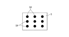
まず、前述したエバポレータ5の温度を検出する図6に示す温度センサS4は、具体的には、図8に示すように、エバポレータ5の広い範囲に渡って分散するようにして複数(実施形態では9個)配設される。なお、図8は、エバポレータ5を空調風の流れ方向から見た図となっており、空調風は図8の紙面直角方向へ流れるものとされている。
First, a plurality of temperature sensors S4 shown in FIG. 6 for detecting the temperature of the
上述のように、温度センサS4を複数(多数)配設するのは、エバポレータ5の温度がその部位によってかなり相違することから、種々の部位について個々に温度を検出するためのものとなっている。換言すれば、局所的に氷結臭を発生させる温度以下になることの防止や、局所的に乾き臭を生じる温度以上になることを防止するためのものとなっている。つまり、エバポレータ5の温度制御を行う場合に、低温側となる氷結防止のための下限温度については、複数の温度センサS4で検出される温度のうちもっとも低い温度を基準に温度制御される(氷結臭の防止)。同様に、乾き臭防止のために、高温側となる上限温度については、複数の温度センサS4で検出される温度のうちもっとも高い温度を基準に温度制御される。なお、乾き臭や氷結臭が問題とならない走行中におけるエバポレータ5の通常の温度範囲のときは、エバポレータ5の中央部に設けた温度センサS4の検出温度に応じて、エバポレータ5のC温度がフィードバック制御される。
As described above, a plurality of (many) temperature sensors S4 are arranged to detect temperatures individually for various parts because the temperature of the
次に、アイドルストップによりエンジンの自動停止と自動再始動とに関連して、エバポレータ5の温度制御の点について説明する。まず、t1時点よりも前のときは、エンジンが駆動されており(エンジン側からの要請によりアイドルストップによるエンジン自動停止が禁止されている状態)、空調制御側からはアイドルストップによるエンジン自動停止の許可信号が出力されている。このとき、ルーフ開時にはルーフ閉時に比して相対的に低い所定温度となるように制御される。例えば、ルーフ閉時では、図8に示す温度センサS4のうち中央部分の温度センサS4により検出される温度が3℃〜4℃の範囲となるように制御される(3℃以下となるとエバポレータ5冷却用のコンプレッサ50をオフし、4℃以上となるとコンプレッサ50をONする)。また、ルーフ開時には、0.5℃〜10℃の範囲となるように制御する(複数の温度センサS4のうちいずれか1つの温度センサが0.5℃以下を検出するとコンプレッサ50がオフされ、いずれか1つの温度センサS4が1℃以上を検出するとコンプレッサ50をONする)。
Next, the temperature control of the
t1時点では、エンジン側においてアイドルストップによるエンジン自動停止の許可状態となり、空調制御側からは既にアイドルストップによるエンジン自動停止の許可信号が出力されていることから、エンジン自動停止とされる。エンジン自動停止されても、空調制御(冷房)は実行されるが、エンジンによる冷却が期待できないエバポレータ5の温度は徐々に上昇されていくことになる。
At the time t1, the engine is in a state of automatic engine stop by idle stop on the engine side, and since the engine automatic stop permission signal by idle stop has already been output from the air conditioning control side, the engine is automatically stopped. Even if the engine is automatically stopped, the air conditioning control (cooling) is executed, but the temperature of the
エバポレータ5の温度が上昇して、あらかじめ設定された上限温度となると、空調制御側からアイドルストップ禁止信号が出力されて、エンジンが自動再始動されることなる。上記上限温度になるまでの経過時間は、ルーフ閉時ではt2時点であり、ルーフ開時ではt2時点よりも遅い時期となるt3時点となる。つまり、ルーフ開時では、ルーフ閉時に比して、エンジン自動停止の期間が長く確保されることになる。エバポレータ5の温度が上昇した状態での空調制御を長い期間続行することは、乗員の空調ニーズに十分に応えるという点では好ましくないものの、ルーフ開時での空調ニーズはルーフ閉時に比して相対的に低下するので、エンジン自動停止の期間を長くしても、乗員に対して不快感を与えてしまう事態は生じがたいものとなる。
When the temperature of the
図10は、前述したエバポレータ5の温度制御に着目したフローチャートである。以下このフローチャートについて説明する。なお、以下の説明で、Qはステップである。
FIG. 10 is a flowchart focusing on the temperature control of the
まず、Q1において、各種センサ等からの信号が読み込まれた後、Q2において、外気温度に基づくエンジン自動停止の禁止条件が成立しているか否かが判別される。このQ2の判別でYESのときは、Q8において、コンプレッサ50について、ルーフ閉時に対応した通常の駆動制御が行われる。すなわち、Q8では、エバポレータ5が、相対的に高い温度範囲(例えば3℃〜4℃)となるように温度制御される。
First, in Q1, after signals from various sensors are read, in Q2, it is determined whether or not a prohibition condition for engine automatic stop based on the outside air temperature is satisfied. When the determination in Q2 is YES, in Q8, the normal drive control corresponding to when the roof is closed is performed for the
上記Q2の判別でNOのときは、Q3において、外気温度が所定温度(例えば20℃)以上であるか否かが判別される。このQ3の判別でNOのときは、冷房(冷風)の要求がないときであるとして、Q8に移行される。 If the determination in Q2 is NO, it is determined in Q3 whether or not the outside air temperature is equal to or higher than a predetermined temperature (for example, 20 ° C.). If the determination in Q3 is NO, it is determined that there is no request for cooling (cool air), and the process proceeds to Q8.
前記Q3の判別でYESのときは、Q4において、吹出温度TAOが算出される。この要求吹出温度は、乗員によりマニュアル設定される設定車室内温度または車室内温度との少なくとも一方あるいは両方に基づいて算出される。 When the determination in Q3 is YES, the blowing temperature TAO is calculated in Q4. The required blowing temperature is calculated based on at least one or both of a set vehicle interior temperature and a vehicle interior temperature manually set by the occupant.
Q4の後、Q5において、要求吹出温度TAOが所定温度(例えば15℃)以下であるか否かが判別される。このQ5の判別でNOのときは、Q8に移行される。Q5の判別でYESのときは、Q6において、ルーフ開時であるか否かが判別される。このQ6の判別でNOのとき(つまりルーフ閉時のとき)は、Q8に移行される。 After Q4, at Q5, it is determined whether or not the required blowing temperature TAO is equal to or lower than a predetermined temperature (for example, 15 ° C.). If the determination in Q5 is NO, the process proceeds to Q8. If YES in Q5, it is determined in Q6 whether the roof is open. When the determination in Q6 is NO (that is, when the roof is closed), the process proceeds to Q8.
上記Q6の判別でYESのときは、Q7において、コンプレッサ50について、ルーフ開時に対応した駆動制御が行われる。すなわち、Q7では、エバポレータ5が、相対的に低い温度範囲(例えば0.5℃〜1℃)となるように温度制御される。
When the determination in Q6 is YES, in Q7, the
ここで、ルーフ開時において、エバポレータ5を低い温度範囲(例えば0.5℃〜1℃)となるように駆動制御することへの変更を、車両の停止が予測されるとき(つまりアイドルストップによるエンジン自動停止が予測されるとき)を条件として行うようにすることができる。車両の停止の予測は、次の信号機がまもなく赤色表示へ変更されることの情報(例えば路車間通信等の利用)を利用すること、所定車速(例えば20km/h)以下となる低速時での減速が検出されたとき、あるいはカメラやレーダからの情報に基づいて前方車両が停止したことが検出されたとき等、適宜の手法によりなし得る。
Here, when the roof is opened, the change to drive control of the
アイドルストップによるエンジン自動停止を実行する場合に、所定の遅延時間(例えば2〜3秒)設定して、この遅延時間中にエバポレータ5を急速に低い温度となるように制御し、この遅延時間経過後にエンジン自動停止を行うようにしてもよい。この場合、アイドルストップによるエンジン自動停止が行われることが確実であることが確認された状態でエバポレータ5の温度を低くするので、不必要にエバポレータ5の温度を低くしてしまう事態を防止する上で好ましいものとなる。
When executing an automatic engine stop by idling stop, a predetermined delay time (for example, 2 to 3 seconds) is set, and the
自動変速機を有する車両において、ルーフ開時での冷房中に車両の減速が検出されたときは、ルーフ閉時の変速パターンよりも高い変速比(減速度が高くなる変速比)となるように変速パターンを変更してもよい。高い変速比とすることにより、エンジン回転数が上昇されて、コンプレッサ50によるエバポレータ5の冷却作用を十分高めることができる。特に、高い変速比としつつエバポレータ5を低い温度となるようにコンプレッサ50を積極的に駆動することにより、減速時でのエネルギ回生という点でも好ましいものとなる。
In a vehicle having an automatic transmission, when deceleration of the vehicle is detected during cooling when the roof is opened, the gear ratio is higher than the gear shift pattern when the roof is closed (the gear ratio that increases the deceleration). The shift pattern may be changed. By setting it as a high gear ratio, an engine speed is raised and the cooling effect | action of the
以上実施形態について説明したが、本発明は、実施形態に限定されるものではなく、特許請求の範囲の記載された範囲において適宜の変更が可能であり、例えば次のような場合をも含むものである。ルーフ開閉式の車両としては、フルオープンを選択できる車両に限らず、例えばタルガトップ式の車両やサンルーフ式の車両等、ルーフの一部が開閉される形式の車両であってもよい。ルーフ開時でのエンジン自動停止時において、空調風の吹出し方向を乗員の上半身付近(特に顔付近)にのみ指向させるようにしてもよく、また乗員が運転席にのみ存在するときは、助手席側用の吹き出し口を閉じて、運転席側の吹き出し口のみを開口させるようにしてもよい。勿論、本発明の目的は、明記されたものに限らず、実質的に好ましいあるいは利点として表現されたものを提供することをも暗黙的に含むものである。 Although the embodiment has been described above, the present invention is not limited to the embodiment, and can be appropriately changed within the scope described in the scope of claims. For example, the invention includes the following cases. . The roof opening / closing type vehicle is not limited to a vehicle that can select full open, but may be a vehicle in which a part of the roof is opened or closed, such as a Targa top type vehicle or a sunroof type vehicle. When the engine is automatically stopped when the roof is open, the direction of the air-conditioning wind may be directed only to the upper body of the occupant (especially the face), and when the occupant is only in the driver's seat The side outlet may be closed, and only the driver side outlet may be opened. Of course, the object of the present invention is not limited to what is explicitly stated, but also implicitly includes providing what is substantially preferred or expressed as an advantage.
本発明はルーフが開閉されると共にエンジンの自動停止を行う車両の空調制御用として好適である。 The present invention is suitable for air conditioning control of a vehicle in which the roof is opened and closed and the engine is automatically stopped.
UK:コントローラ(空調制御用)
EG:エンジン
K:空調システム
S4:温度センサ(エバポレータ温度検出用)
S20:センサ(ルーフ開閉検出用)
4:ブロアファン
5:エバポレータ
10:ヒータコア
11:エアミックスダンパ
11A:モータ(アクチュエータ)
11B:開度センサ
12:エアミックスダンパ
12A:モータ(アクチュエータ)
12B:開度センサ
50:コンプレッサ
55:コンデンサ
60:ウオータポンプ
UK: Controller (for air conditioning control)
EG: Engine K: Air conditioning system S4: Temperature sensor (for detecting evaporator temperature)
S20: Sensor (for roof open / close detection)
4: Blower fan 5: Evaporator 10: Heater core 11:
11B: Opening sensor 12:
12B: Opening sensor 50: Compressor 55: Condenser 60: Water pump
Claims (6)
エンジンを駆動源として冷却される空調用のエバポレータを備えた空調装置と、
前記エバポレータの温度を検出するエバポ温度検出手段と、
前記エバポ温度検出手段によって検出されるエバポレータの温度が、所定温度となるように制御するエバポ温度制御手段と、
車両停止を含むアイドルストップ条件が成立したときにエンジン自動停止を行う一方、前記エバポ温度検出手段によって検出される温度が前記所定温度よりも高温に設定された上限温度以上となったときにエンジン自動再始動を行うアイドルストップ制御手段と、
前記所定温度を、ルーフ開時にはルーフ閉時に比して低い温度に変更する所定温度変更手段と、
を備えていることを特徴とする車両用空調制御装置。 A vehicle air conditioning control device for a vehicle having a roof that can be opened and closed,
An air conditioner equipped with an evaporator for air conditioning cooled by an engine as a drive source;
An evaporator temperature detecting means for detecting the temperature of the evaporator;
Evaporator temperature control means for controlling the evaporator temperature detected by the evaporator temperature detection means to be a predetermined temperature;
The engine is automatically stopped when an idle stop condition including a vehicle stop is satisfied, and when the temperature detected by the evaporation temperature detecting means is equal to or higher than the upper limit temperature set higher than the predetermined temperature, the engine is automatically stopped. Idle stop control means for performing restart,
A predetermined temperature changing means for changing the predetermined temperature to a lower temperature when the roof is open than when the roof is closed;
A vehicle air-conditioning control device comprising:
前記所定温度が、前記エバポレータの凍結度が所定値よりも高まらない温度に設定される、ことを特徴とする車両用空調制御装置。 In claim 1,
The vehicle air conditioning control device, wherein the predetermined temperature is set to a temperature at which the freezing degree of the evaporator does not rise above a predetermined value.
前記上限温度が、乾き臭を生じる温度よりも低い温度に設定されている、ことを特徴とする車両用空調制御装置。 In claim 1 or claim 2,
The vehicle air conditioning control apparatus, wherein the upper limit temperature is set to a temperature lower than a temperature at which a dry odor is generated.
車両の停止を予測する停止予測手段を備え、
前記所定温度変更手段は、ルーフ開時に、前記停止予測手段で車両の停止が予測されたことを条件として、前記所定温度を低い温度に変更する、
ことを特徴とする車両用空調制御装置。 In any one of Claims 1 thru | or 3,
A stop prediction means for predicting the stop of the vehicle,
The predetermined temperature changing means changes the predetermined temperature to a lower temperature when the roof is opened, on condition that the stop prediction of the vehicle is predicted by the stop prediction means.
A vehicle air-conditioning control device.
ルーフ開時において、前記アイドルストップ制御手段は車両が停止された時点から所定時間経過した後にエンジン自動停止を行う一方、前記所定温度変更手段は車両が停止された時点から前記所定時間が経過するまでの期間において前記所定温度を低い温度に変更する、ことを特徴とする車両用空調制御装置。 In any one of Claims 1 thru | or 3,
When the roof is opened, the idle stop control means automatically stops the engine after a predetermined time elapses from the time when the vehicle is stopped, while the predetermined temperature changing means is operated until the predetermined time elapses from the time when the vehicle is stopped. The vehicle air-conditioning control apparatus is characterized in that the predetermined temperature is changed to a low temperature during the period.
前記車両が、所定の変速パターンに基づいて変速を行う自動変速機を有しており、
ルーフ開時に冷房中かつ車両の減速が検出されたときには、前記変速パターンをルーフ閉時に比して高い変速比に変更させる変速パターン変更手段をさらに備えている、
ことを特徴とする車両用空調制御装置。 In any one of Claims 1 thru | or 5,
The vehicle has an automatic transmission that performs a shift based on a predetermined shift pattern;
Shifting pattern changing means for changing the shift pattern to a higher gear ratio than when the roof is closed when cooling is detected when the roof is opened and when the vehicle is decelerated, is further provided.
A vehicle air-conditioning control device.
Priority Applications (1)
| Application Number | Priority Date | Filing Date | Title |
|---|---|---|---|
| JP2014108774A JP6079699B2 (en) | 2014-05-27 | 2014-05-27 | Air conditioning control device for vehicles |
Applications Claiming Priority (1)
| Application Number | Priority Date | Filing Date | Title |
|---|---|---|---|
| JP2014108774A JP6079699B2 (en) | 2014-05-27 | 2014-05-27 | Air conditioning control device for vehicles |
Publications (2)
| Publication Number | Publication Date |
|---|---|
| JP2015223896A JP2015223896A (en) | 2015-12-14 |
| JP6079699B2 true JP6079699B2 (en) | 2017-02-15 |
Family
ID=54841012
Family Applications (1)
| Application Number | Title | Priority Date | Filing Date |
|---|---|---|---|
| JP2014108774A Expired - Fee Related JP6079699B2 (en) | 2014-05-27 | 2014-05-27 | Air conditioning control device for vehicles |
Country Status (1)
| Country | Link |
|---|---|
| JP (1) | JP6079699B2 (en) |
Families Citing this family (3)
| Publication number | Priority date | Publication date | Assignee | Title |
|---|---|---|---|---|
| JP6300191B1 (en) * | 2016-10-14 | 2018-03-28 | マツダ株式会社 | Vehicle control device |
| JP7172607B2 (en) * | 2019-01-08 | 2022-11-16 | トヨタ自動車株式会社 | engine controller |
| JP7524263B2 (en) | 2022-09-22 | 2024-07-29 | 本田技研工業株式会社 | Power supply control device and power supply control method |
Family Cites Families (11)
| Publication number | Priority date | Publication date | Assignee | Title |
|---|---|---|---|---|
| JPH1071846A (en) * | 1996-08-30 | 1998-03-17 | Calsonic Corp | Air conditioner for automobile |
| JP4174929B2 (en) * | 1998-10-23 | 2008-11-05 | 株式会社デンソー | Air conditioner for vehicles |
| JP2000229516A (en) * | 1998-12-11 | 2000-08-22 | Calsonic Kansei Corp | Controller for hybrid compressor |
| JP2001121956A (en) * | 1999-10-29 | 2001-05-08 | Denso Corp | Air conditioner for vehicle |
| JP2001310620A (en) * | 2000-04-26 | 2001-11-06 | Denso Corp | Air conditioner for vehicle |
| JP4682489B2 (en) * | 2001-09-17 | 2011-05-11 | 株式会社デンソー | Air conditioner for vehicles |
| JP3974826B2 (en) * | 2002-07-16 | 2007-09-12 | トヨタ自動車株式会社 | Air conditioner for vehicles |
| JP2005188848A (en) * | 2003-12-26 | 2005-07-14 | Zexel Valeo Climate Control Corp | Air conditioner |
| JP4238767B2 (en) * | 2004-04-16 | 2009-03-18 | 株式会社デンソー | Air conditioner for vehicles |
| JP2008081038A (en) * | 2006-09-28 | 2008-04-10 | Denso Corp | Air conditioner for convertible |
| JP5935625B2 (en) * | 2012-09-20 | 2016-06-15 | 株式会社デンソー | Refrigeration cycle controller |
-
2014
- 2014-05-27 JP JP2014108774A patent/JP6079699B2/en not_active Expired - Fee Related
Also Published As
| Publication number | Publication date |
|---|---|
| JP2015223896A (en) | 2015-12-14 |
Similar Documents
| Publication | Publication Date | Title |
|---|---|---|
| JP6172017B2 (en) | Air conditioning control device for vehicles | |
| JP6040622B2 (en) | Air conditioning control device for vehicles | |
| JP6032073B2 (en) | Air conditioning control device for vehicles | |
| JP6142850B2 (en) | Vehicle control device | |
| JP6489223B2 (en) | Program used for engine control device, air conditioning system, and air conditioning control device | |
| JP5012491B2 (en) | Control device for vehicle air conditioner and vehicle | |
| JP6079699B2 (en) | Air conditioning control device for vehicles | |
| JP6070068B2 (en) | Air conditioning control device for vehicles | |
| JP6102847B2 (en) | Vehicle control device | |
| JP2001180246A (en) | Vehicle air conditioner | |
| JP6102875B2 (en) | Vehicle control device | |
| JP6090235B2 (en) | Air conditioning control device for vehicles | |
| JP6090218B2 (en) | Air conditioning control device for vehicles | |
| JP2009298239A (en) | Vehicular air-conditioning control device | |
| JP5966983B2 (en) | Air conditioning control device for vehicles | |
| JP6107780B2 (en) | Vehicle control device | |
| JP6160533B2 (en) | Air conditioning control device for vehicles | |
| JP6107781B2 (en) | Vehicle control device | |
| JP6036430B2 (en) | Air conditioning control device for vehicles | |
| JP2014180887A (en) | Vehicle air conditioner control device | |
| JP6142851B2 (en) | Vehicle control device | |
| JP6102848B2 (en) | Vehicle control device | |
| JP6164185B2 (en) | Vehicle control device |
Legal Events
| Date | Code | Title | Description |
|---|---|---|---|
| A621 | Written request for application examination |
Free format text: JAPANESE INTERMEDIATE CODE: A621 Effective date: 20160225 |
|
| A977 | Report on retrieval |
Free format text: JAPANESE INTERMEDIATE CODE: A971007 Effective date: 20161208 |
|
| TRDD | Decision of grant or rejection written | ||
| A01 | Written decision to grant a patent or to grant a registration (utility model) |
Free format text: JAPANESE INTERMEDIATE CODE: A01 Effective date: 20161220 |
|
| A61 | First payment of annual fees (during grant procedure) |
Free format text: JAPANESE INTERMEDIATE CODE: A61 Effective date: 20170102 |
|
| R150 | Certificate of patent or registration of utility model |
Ref document number: 6079699 Country of ref document: JP Free format text: JAPANESE INTERMEDIATE CODE: R150 |
|
| LAPS | Cancellation because of no payment of annual fees |