JP6076224B2 - Semiconductor device and manufacturing method thereof - Google Patents
Semiconductor device and manufacturing method thereof Download PDFInfo
- Publication number
- JP6076224B2 JP6076224B2 JP2013184502A JP2013184502A JP6076224B2 JP 6076224 B2 JP6076224 B2 JP 6076224B2 JP 2013184502 A JP2013184502 A JP 2013184502A JP 2013184502 A JP2013184502 A JP 2013184502A JP 6076224 B2 JP6076224 B2 JP 6076224B2
- Authority
- JP
- Japan
- Prior art keywords
- region
- semiconductor
- semiconductor region
- type semiconductor
- element isolation
- Prior art date
- Legal status (The legal status is an assumption and is not a legal conclusion. Google has not performed a legal analysis and makes no representation as to the accuracy of the status listed.)
- Active
Links
Images


Classifications
-
- H—ELECTRICITY
- H10—SEMICONDUCTOR DEVICES; ELECTRIC SOLID-STATE DEVICES NOT OTHERWISE PROVIDED FOR
- H10D—INORGANIC ELECTRIC SEMICONDUCTOR DEVICES
- H10D86/00—Integrated devices formed in or on insulating or conducting substrates, e.g. formed in silicon-on-insulator [SOI] substrates or on stainless steel or glass substrates
- H10D86/201—Integrated devices formed in or on insulating or conducting substrates, e.g. formed in silicon-on-insulator [SOI] substrates or on stainless steel or glass substrates the substrates comprising an insulating layer on a semiconductor body, e.g. SOI
-
- H—ELECTRICITY
- H10—SEMICONDUCTOR DEVICES; ELECTRIC SOLID-STATE DEVICES NOT OTHERWISE PROVIDED FOR
- H10D—INORGANIC ELECTRIC SEMICONDUCTOR DEVICES
- H10D30/00—Field-effect transistors [FET]
- H10D30/01—Manufacture or treatment
- H10D30/021—Manufacture or treatment of FETs having insulated gates [IGFET]
- H10D30/0223—Manufacture or treatment of FETs having insulated gates [IGFET] having source and drain regions or source and drain extensions self-aligned to sides of the gate
- H10D30/0227—Manufacture or treatment of FETs having insulated gates [IGFET] having source and drain regions or source and drain extensions self-aligned to sides of the gate having both lightly-doped source and drain extensions and source and drain regions self-aligned to the sides of the gate, e.g. lightly-doped drain [LDD] MOSFET or double-diffused drain [DDD] MOSFET
- H10D30/0229—Manufacture or treatment of FETs having insulated gates [IGFET] having source and drain regions or source and drain extensions self-aligned to sides of the gate having both lightly-doped source and drain extensions and source and drain regions self-aligned to the sides of the gate, e.g. lightly-doped drain [LDD] MOSFET or double-diffused drain [DDD] MOSFET forming drain regions and lightly-doped drain [LDD] simultaneously, e.g. using implantation through a T-shaped mask
-
- H—ELECTRICITY
- H10—SEMICONDUCTOR DEVICES; ELECTRIC SOLID-STATE DEVICES NOT OTHERWISE PROVIDED FOR
- H10D—INORGANIC ELECTRIC SEMICONDUCTOR DEVICES
- H10D30/00—Field-effect transistors [FET]
- H10D30/01—Manufacture or treatment
- H10D30/021—Manufacture or treatment of FETs having insulated gates [IGFET]
- H10D30/028—Manufacture or treatment of FETs having insulated gates [IGFET] of double-diffused metal oxide semiconductor [DMOS] FETs
- H10D30/0281—Manufacture or treatment of FETs having insulated gates [IGFET] of double-diffused metal oxide semiconductor [DMOS] FETs of lateral DMOS [LDMOS] FETs
-
- H—ELECTRICITY
- H10—SEMICONDUCTOR DEVICES; ELECTRIC SOLID-STATE DEVICES NOT OTHERWISE PROVIDED FOR
- H10D—INORGANIC ELECTRIC SEMICONDUCTOR DEVICES
- H10D30/00—Field-effect transistors [FET]
- H10D30/60—Insulated-gate field-effect transistors [IGFET]
-
- H—ELECTRICITY
- H10—SEMICONDUCTOR DEVICES; ELECTRIC SOLID-STATE DEVICES NOT OTHERWISE PROVIDED FOR
- H10D—INORGANIC ELECTRIC SEMICONDUCTOR DEVICES
- H10D30/00—Field-effect transistors [FET]
- H10D30/60—Insulated-gate field-effect transistors [IGFET]
- H10D30/601—Insulated-gate field-effect transistors [IGFET] having lightly-doped drain or source extensions, e.g. LDD IGFETs or DDD IGFETs
- H10D30/603—Insulated-gate field-effect transistors [IGFET] having lightly-doped drain or source extensions, e.g. LDD IGFETs or DDD IGFETs having asymmetry in the channel direction, e.g. lateral high-voltage MISFETs having drain offset region or extended drain IGFETs [EDMOS]
-
- H—ELECTRICITY
- H10—SEMICONDUCTOR DEVICES; ELECTRIC SOLID-STATE DEVICES NOT OTHERWISE PROVIDED FOR
- H10D—INORGANIC ELECTRIC SEMICONDUCTOR DEVICES
- H10D30/00—Field-effect transistors [FET]
- H10D30/60—Insulated-gate field-effect transistors [IGFET]
- H10D30/64—Double-diffused metal-oxide semiconductor [DMOS] FETs
- H10D30/65—Lateral DMOS [LDMOS] FETs
- H10D30/657—Lateral DMOS [LDMOS] FETs having substrates comprising insulating layers, e.g. SOI-LDMOS transistors
-
- H—ELECTRICITY
- H10—SEMICONDUCTOR DEVICES; ELECTRIC SOLID-STATE DEVICES NOT OTHERWISE PROVIDED FOR
- H10D—INORGANIC ELECTRIC SEMICONDUCTOR DEVICES
- H10D62/00—Semiconductor bodies, or regions thereof, of devices having potential barriers
- H10D62/10—Shapes, relative sizes or dispositions of the regions of the semiconductor bodies; Shapes of the semiconductor bodies
- H10D62/113—Isolations within a component, i.e. internal isolations
- H10D62/115—Dielectric isolations, e.g. air gaps
- H10D62/116—Dielectric isolations, e.g. air gaps adjoining the input or output regions of field-effect devices, e.g. adjoining source or drain regions
-
- H—ELECTRICITY
- H10—SEMICONDUCTOR DEVICES; ELECTRIC SOLID-STATE DEVICES NOT OTHERWISE PROVIDED FOR
- H10D—INORGANIC ELECTRIC SEMICONDUCTOR DEVICES
- H10D62/00—Semiconductor bodies, or regions thereof, of devices having potential barriers
- H10D62/60—Impurity distributions or concentrations
-
- H—ELECTRICITY
- H10—SEMICONDUCTOR DEVICES; ELECTRIC SOLID-STATE DEVICES NOT OTHERWISE PROVIDED FOR
- H10D—INORGANIC ELECTRIC SEMICONDUCTOR DEVICES
- H10D64/00—Electrodes of devices having potential barriers
- H10D64/60—Electrodes characterised by their materials
- H10D64/62—Electrodes ohmically coupled to a semiconductor
-
- H—ELECTRICITY
- H10—SEMICONDUCTOR DEVICES; ELECTRIC SOLID-STATE DEVICES NOT OTHERWISE PROVIDED FOR
- H10D—INORGANIC ELECTRIC SEMICONDUCTOR DEVICES
- H10D86/00—Integrated devices formed in or on insulating or conducting substrates, e.g. formed in silicon-on-insulator [SOI] substrates or on stainless steel or glass substrates
- H10D86/01—Manufacture or treatment
-
- H10P30/222—
-
- H10P90/1906—
-
- H10W10/0143—
-
- H10W10/061—
-
- H10W10/17—
-
- H10W10/181—
Landscapes
- Engineering & Computer Science (AREA)
- Metal-Oxide And Bipolar Metal-Oxide Semiconductor Integrated Circuits (AREA)
- Physics & Mathematics (AREA)
- Manufacturing & Machinery (AREA)
- General Physics & Mathematics (AREA)
- Computer Hardware Design (AREA)
- Microelectronics & Electronic Packaging (AREA)
- Power Engineering (AREA)
- Condensed Matter Physics & Semiconductors (AREA)
- Element Separation (AREA)
- High Energy & Nuclear Physics (AREA)
- Thin Film Transistor (AREA)
- Chemical & Material Sciences (AREA)
- Crystallography & Structural Chemistry (AREA)
- Health & Medical Sciences (AREA)
- Toxicology (AREA)
Description
本発明は、半導体装置およびその製造方法に関し、例えば、MISFETを有する半導体装置およびその製造方法に好適に利用できるものである。 The present invention relates to a semiconductor device and a manufacturing method thereof, and can be suitably used for, for example, a semiconductor device having a MISFET and a manufacturing method thereof.
SOI(Silicon On Insulator)基板を用いて半導体装置を製造する技術がある。SOI基板は、支持基板上に絶縁層を介して半導体層を形成したものであり、このSOI基板の半導体層にMISFET(Metal Insulator Semiconductor Field Effect Transistor)などが形成される。 There is a technique for manufacturing a semiconductor device using an SOI (Silicon On Insulator) substrate. The SOI substrate is obtained by forming a semiconductor layer on a support substrate via an insulating layer, and a MISFET (Metal Insulator Semiconductor Field Effect Transistor) or the like is formed on the semiconductor layer of the SOI substrate.
特開2011−40458号公報(特許文献1)、特開2009−135140号公報(特許文献2)、および特表2001−527293号公報(特許文献3)には、SOI基板を用いた半導体装置に関する技術が記載されている。 Japanese Unexamined Patent Application Publication No. 2011-40458 (Patent Document 1), Japanese Unexamined Patent Application Publication No. 2009-135140 (Patent Document 2), and Japanese Translation of PCT International Publication No. 2001-527293 (Patent Document 3) relate to a semiconductor device using an SOI substrate. The technology is described.
SOI基板にMISFETを形成した半導体装置においても、できるだけ性能を向上させることが望まれる。 Even in a semiconductor device in which a MISFET is formed on an SOI substrate, it is desired to improve the performance as much as possible.
その他の課題と新規な特徴は、本明細書の記述および添付図面から明らかになるであろう。 Other problems and novel features will become apparent from the description of the specification and the accompanying drawings.
一実施の形態によれば、半導体装置は、半導体基板上に絶縁層を介して形成された半導体層からなり、前記半導体層および前記絶縁層を貫通する素子分離領域によってそれぞれ囲まれた第1活性領域および第2活性領域と、前記素子分離領域によってそれぞれ平面的に囲まれ、かつ、前記半導体層および前記絶縁層が除去されている第1領域および第2領域とを有している。前記第1活性領域には第1MISFETが形成され、前記第2活性領域には第2MISFETが形成されている。平面視で前記第1活性領域および前記第1領域を含むように、前記半導体基板内に第1導電型の第2半導体領域が形成され、平面視で前記第1活性領域および前記第1領域を含むように、前記半導体基板内に前記第1導電型で前記第1半導体領域よりも高不純物濃度の第2半導体領域が形成されている。前記第2半導体領域は、前記第1半導体領域に内包され、前記第2半導体領域の底面は、平面視で前記第1活性領域と前記第1領域との間に介在する部分の前記素子分離領域の底面よりも深い。平面視で前記第2活性領域および前記第2領域を含むように、前記半導体基板内に第2導電型の第3半導体領域が形成され、平面視で前記第2活性領域および前記第2領域を含むように、前記半導体基板内に前記第2導電型で前記第3半導体領域よりも高不純物濃度の第4半導体領域が形成されている。前記第4半導体領域は、前記第3半導体領域に内包され、前記第4半導体領域の底面は、平面視で前記第2活性領域と前記第2領域との間に介在する部分の前記素子分離領域の底面よりも深い。 According to one embodiment, a semiconductor device includes a semiconductor layer formed on a semiconductor substrate via an insulating layer, and is surrounded by an element isolation region penetrating the semiconductor layer and the insulating layer, respectively. A region and a second active region; and a first region and a second region surrounded by the element isolation region in a planar manner and from which the semiconductor layer and the insulating layer are removed. A first MISFET is formed in the first active region, and a second MISFET is formed in the second active region. A second semiconductor region of the first conductivity type is formed in the semiconductor substrate so as to include the first active region and the first region in a plan view, and the first active region and the first region are formed in a plan view. A second semiconductor region of the first conductivity type and having a higher impurity concentration than the first semiconductor region is formed in the semiconductor substrate. The second semiconductor region is included in the first semiconductor region, and a bottom surface of the second semiconductor region is a portion of the element isolation region interposed between the first active region and the first region in plan view Deeper than the bottom. A third semiconductor region of the second conductivity type is formed in the semiconductor substrate so as to include the second active region and the second region in a plan view, and the second active region and the second region are formed in a plan view. A fourth semiconductor region of the second conductivity type and having a higher impurity concentration than the third semiconductor region is formed in the semiconductor substrate. The fourth semiconductor region is included in the third semiconductor region, and a bottom surface of the fourth semiconductor region is a portion of the element isolation region interposed between the second active region and the second region in plan view Deeper than the bottom.
また、一実施の形態によれば、半導体装置の製造方法は、半導体基板上に絶縁層を介して半導体層が形成された基板に、前記半導体層および前記絶縁層を貫通する素子分離領域を形成する。これにより、半導体基板の第1領域、第2領域、第3領域および第4領域は、それぞれ前記素子分離領域で平面的に囲まれる。素子分離領域の形成後、前記半導体基板に、第1導電型の第1半導体領域および第2半導体領域と、第2導電型の第3半導体領域および第4半導体領域とを形成する。また、素子分離領域の形成後、前記第1領域および前記第2領域の前記半導体基板上の前記半導体層と前記絶縁層とを除去する。その後、前記第3領域の前記半導体基板上に前記絶縁層を介して残存している前記半導体層に、第1MISFETを形成し、前記第4領域の前記半導体基板上に前記絶縁層を介して残存している前記半導体層に、第2MISFETを形成する。前記第2半導体領域は、前記第1半導体領域よりも高不純物濃度であり、前記第1半導体領域に内包され、前記第2半導体領域は、平面視で前記第1領域および前記第3領域を含み、前記第2半導体領域の底面は、平面視で前記第1領域と前記第3領域との間に介在する部分の前記素子分離領域の底面よりも深い。前記第4半導体領域は、前記第3半導体領域よりも高不純物濃度であり、前記第3半導体領域に内包され、前記第4半導体領域は、前記第2領域および前記第4領域を平面視で内包し、前記第4半導体領域の底面は、平面視で前記第2領域と前記第4領域との間に介在する部分の前記素子分離領域の底面よりも深い。 According to one embodiment, a method for manufacturing a semiconductor device includes: forming a semiconductor isolation layer penetrating the semiconductor layer and the insulating layer on a semiconductor substrate on which a semiconductor layer is formed via an insulating layer; To do. Thereby, the first region, the second region, the third region, and the fourth region of the semiconductor substrate are each planarly surrounded by the element isolation region. After the element isolation region is formed, a first conductive type first semiconductor region and a second semiconductor region, and a second conductive type third semiconductor region and a fourth semiconductor region are formed on the semiconductor substrate. Further, after the element isolation region is formed, the semiconductor layer and the insulating layer on the semiconductor substrate in the first region and the second region are removed. Thereafter, a first MISFET is formed on the semiconductor layer remaining on the semiconductor substrate in the third region via the insulating layer, and remaining on the semiconductor substrate in the fourth region via the insulating layer. A second MISFET is formed in the semiconductor layer. The second semiconductor region has a higher impurity concentration than the first semiconductor region and is included in the first semiconductor region, and the second semiconductor region includes the first region and the third region in plan view. The bottom surface of the second semiconductor region is deeper than the bottom surface of the element isolation region at a portion interposed between the first region and the third region in plan view. The fourth semiconductor region has a higher impurity concentration than the third semiconductor region and is included in the third semiconductor region, and the fourth semiconductor region includes the second region and the fourth region in plan view. The bottom surface of the fourth semiconductor region is deeper than the bottom surface of the element isolation region at a portion interposed between the second region and the fourth region in plan view.
一実施の形態によれば、半導体装置の性能を向上させることができる。 According to one embodiment, the performance of a semiconductor device can be improved.
以下の実施の形態においては便宜上その必要があるときは、複数のセクションまたは実施の形態に分割して説明するが、特に明示した場合を除き、それらはお互いに無関係なものではなく、一方は他方の一部または全部の変形例、詳細、補足説明等の関係にある。また、以下の実施の形態において、要素の数等(個数、数値、量、範囲等を含む)に言及する場合、特に明示した場合および原理的に明らかに特定の数に限定される場合等を除き、その特定の数に限定されるものではなく、特定の数以上でも以下でもよい。さらに、以下の実施の形態において、その構成要素(要素ステップ等も含む)は、特に明示した場合および原理的に明らかに必須であると考えられる場合等を除き、必ずしも必須のものではないことは言うまでもない。同様に、以下の実施の形態において、構成要素等の形状、位置関係等に言及するときは、特に明示した場合および原理的に明らかにそうでないと考えられる場合等を除き、実質的にその形状等に近似または類似するもの等を含むものとする。このことは、上記数値および範囲についても同様である。 In the following embodiments, when it is necessary for the sake of convenience, the description will be divided into a plurality of sections or embodiments. However, unless otherwise specified, they are not irrelevant to each other. There are some or all of the modifications, details, supplementary explanations, and the like. Further, in the following embodiments, when referring to the number of elements (including the number, numerical value, quantity, range, etc.), especially when clearly indicated and when clearly limited to a specific number in principle, etc. Except, it is not limited to the specific number, and may be more or less than the specific number. Further, in the following embodiments, the constituent elements (including element steps and the like) are not necessarily indispensable unless otherwise specified and apparently essential in principle. Needless to say. Similarly, in the following embodiments, when referring to the shapes, positional relationships, etc. of the components, etc., the shapes are substantially the same unless otherwise specified, or otherwise apparent in principle. And the like are included. The same applies to the above numerical values and ranges.
以下、実施の形態を図面に基づいて詳細に説明する。なお、実施の形態を説明するための全図において、同一の機能を有する部材には同一の符号を付し、その繰り返しの説明は省略する。また、以下の実施の形態では、特に必要なとき以外は同一または同様な部分の説明を原則として繰り返さない。 Hereinafter, embodiments will be described in detail with reference to the drawings. Note that components having the same function are denoted by the same reference symbols throughout the drawings for describing the embodiments, and the repetitive description thereof will be omitted. In the following embodiments, the description of the same or similar parts will not be repeated in principle unless particularly necessary.
また、実施の形態で用いる図面においては、断面図であっても図面を見易くするためにハッチングを省略する場合もある。また、平面図であっても図面を見易くするためにハッチングを付す場合もある。 In the drawings used in the embodiments, hatching may be omitted even in a cross-sectional view so as to make the drawings easy to see. Further, even a plan view may be hatched to make the drawing easy to see.
(実施の形態1)
<半導体装置の構造について>
本実施の形態の半導体装置を図面を参照して説明する。図1は、本実施の形態の半導体装置の要部平面図であり、図2〜5は、本実施の形態の半導体装置の要部断面図である。図2は、図1のA−A線の断面図にほぼ対応している。また、図3には、2つの断面図が示されているが、図3の左側の断面図は、図1のB−B線の断面図にほぼ対応し、図3の右側の断面図は、図1のC−C線の断面図にほぼ対応している。また、図5には、2つの断面図が示されているが、図5の左側の断面図は、図1のD−D線の断面図にほぼ対応し、図5の右側の断面図は、図1のE−E線の断面図にほぼ対応している。
(Embodiment 1)
<Structure of semiconductor device>
The semiconductor device of the present embodiment will be described with reference to the drawings. FIG. 1 is a main part plan view of the semiconductor device of the present embodiment, and FIGS. 2 to 5 are main part cross-sectional views of the semiconductor device of the present embodiment. 2 substantially corresponds to the cross-sectional view taken along the line AA in FIG. 3 shows two cross-sectional views. The left-side cross-sectional view in FIG. 3 substantially corresponds to the cross-sectional view taken along the line BB in FIG. 1, and the right-side cross-sectional view in FIG. 1 substantially corresponds to the cross-sectional view taken along the line CC of FIG. 5 shows two cross-sectional views. The left-side cross-sectional view in FIG. 5 substantially corresponds to the cross-sectional view along the line DD in FIG. 1, and the right-side cross-sectional view in FIG. 1 substantially corresponds to the cross-sectional view taken along the line E-E in FIG.
また、図4は、図3と同じ領域の断面図が示されており、図4の左側の断面図は、図1のB−B線の断面図にほぼ対応し、図4の右側の断面図は、図1のC−C線の断面図にほぼ対応している。但し、図3では、半導体層SMがどの領域であるのかが分かりやすいように、半導体層SM全体にドットのハッチングを付して示してあり、n−型半導体領域EX1、n+型半導体領域HR1、p−型半導体領域EX2およびp+型半導体領域HR2の形成領域についての図示はしていない。また、図4では、n−型半導体領域EX1とn+型半導体領域HR1とp−型半導体領域EX2とp+型半導体領域HR2とがそれぞれどの領域であるかが分かりやすいように、n−型半導体領域EX1とn+型半導体領域HR1とp−型半導体領域EX2とp+型半導体領域HR2とにそれぞれ斜線のハッチングを付して示してある。従って、図3と図4とを合わせて見れば、半導体層SMの構成と、半導体層SMにおけるn−型半導体領域EX1とn+型半導体領域HR1とp−型半導体領域EX2とp+型半導体領域HR2との形成領域とを、理解しやすい。 4 is a cross-sectional view of the same region as FIG. 3, and the cross-sectional view on the left side of FIG. 4 substantially corresponds to the cross-sectional view taken along the line BB of FIG. The figure substantially corresponds to the cross-sectional view taken along the line CC in FIG. However, in FIG. 3, for easy understanding of which region the semiconductor layer SM is, the entire semiconductor layer SM is shown by hatching dots, and the n − type semiconductor region EX1 and the n + type semiconductor region HR1 are shown. The formation regions of the p − type semiconductor region EX2 and the p + type semiconductor region HR2 are not shown. Further, in FIG. 4, n - -type semiconductor region EX1 and the n + -type semiconductor regions HR1 and p - as the type semiconductor region EX2 and the p + -type semiconductor region HR2 is easy to understand whether any respective regions, n - -type The semiconductor region EX1, the n + type semiconductor region HR1, the p − type semiconductor region EX2, and the p + type semiconductor region HR2 are indicated by hatching. 3 and 4 together, the configuration of the semiconductor layer SM, the n − type semiconductor region EX1, the n + type semiconductor region HR1, the p − type semiconductor region EX2, and the p + type semiconductor in the semiconductor layer SM. It is easy to understand the formation region with the region HR2.
図1〜図5に示される本実施の形態の半導体装置は、MISFET(Metal Insulator Semiconductor Field Effect Transistor、MIS型電界効果トランジスタ)として、nチャネル型MISFETQnとpチャネル型MISFETQpとを備えた半導体装置である。 The semiconductor device of the present embodiment shown in FIGS. 1 to 5 is a semiconductor device provided with an n-channel type MISFET Qn and a p-channel type MISFET Qp as MISFETs (Metal Insulator Semiconductor Field Effect Transistors). is there.
また、図1〜図5に示される本実施の形態の半導体装置は、SOI(SOI:Silicon On Insulator)基板1を用いた半導体装置である。
The semiconductor device of the present embodiment shown in FIGS. 1 to 5 is a semiconductor device using an SOI (SOI: Silicon On Insulator)
SOI基板1は、半導体基板(支持基板)SBと、半導体基板SBの主面上に形成された絶縁層(埋め込み絶縁膜)BXと、絶縁層BXの上面上に形成された半導体層SMと、を有している。半導体基板SBは、絶縁層BXとそれよりも上の構造とを支持する支持基板である。これら半導体基板SB、絶縁層BXおよび半導体層SMにより、SOI基板1が形成されている。SOI基板1の主面には、nチャネル型のMISFETであるMISFETQnと、pチャネル型のMISFETであるMISFETQpとが形成されている。
The
半導体基板SBは、単結晶シリコンなどからなる。絶縁層BXは、例えば酸化シリコンからなる。絶縁層BXが酸化シリコン膜の場合、絶縁層BXは、埋め込み酸化膜、すなわちBOX(Buried Oxide)層とみなすこともできる。半導体層SMは、単結晶シリコンなどからなる。半導体層SMは、SOI層とみなすこともできる。 The semiconductor substrate SB is made of single crystal silicon or the like. The insulating layer BX is made of, for example, silicon oxide. When the insulating layer BX is a silicon oxide film, the insulating layer BX can be regarded as a buried oxide film, that is, a BOX (Buried Oxide) layer. The semiconductor layer SM is made of single crystal silicon or the like. The semiconductor layer SM can also be regarded as an SOI layer.
SOI基板1には、素子分離領域(素子分離構造)STが形成されている。この素子分離領域STは、素子分離溝(素子分離用の溝)に埋め込まれた絶縁膜(例えば酸化シリコン膜)により形成されている。素子分離溝およびそれを埋めている素子分離領域STは、半導体層SMおよび絶縁層BXを貫通して、その底部が半導体基板SBの厚みの途中に達しており、素子分離領域STの下部は、半導体基板SB内に位置している。すなわち、半導体層SM、絶縁層BXおよび半導体基板SBにかけて形成された素子分離溝に、素子分離領域STが埋め込まれた状態となっている。このため、素子分離領域STの底面(下面)は、半導体基板SBの厚みの途中に位置している。つまり、素子分離領域STは、一部が、絶縁層BXの下面よりも下方に位置している。
An element isolation region (element isolation structure) ST is formed on the
本実施の形態のSOI基板1は、nチャネル型MISFETQnが形成される領域であるnMIS形成領域1Aと、pチャネル型MISFETQpが形成される領域であるpMIS形成領域1Bと、nMIS形成領域1Aの半導体基板SBに給電するための給電領域2Aと、pMIS形成領域1Bの半導体基板SBに給電するための給電領域2Bとを有している。これらの領域1A,1B,2A,2Bは、平面視での領域(平面領域)である。nMIS形成領域1AとpMIS形成領域1Bと給電領域2Aと給電領域2Bとは、それぞれ、素子分離領域STで区画されている。すなわち、平面視において、nMIS形成領域1AとpMIS形成領域1Bと給電領域2Aと給電領域2Bとは、それぞれ、素子分離領域STで周囲を囲まれている。従って、nMIS形成領域1AとpMIS形成領域1Bと給電領域2Aと給電領域2Bとは、それぞれ、素子分離領域STで囲まれた活性領域とみなすことができる。また、平面視において、給電領域2AとnMIS形成領域1Aとは、間に素子分離領域STを介して隣り合っており、また、平面視において、給電領域2BとpMIS形成領域1Bとは、間に素子分離領域STを介して隣り合っている。
The
nMIS形成領域1Aの半導体層SMにnチャネル型MISFETQnが形成され、pMIS形成領域1Bの半導体層SMにpチャネル型MISFETQpが形成されている。SOI基板1において、nMIS形成領域1Aの半導体層SMと、pMIS形成領域1Bの半導体層SMとは、それぞれ、素子分離領域STに平面的に囲まれて区画されている。すなわち、nMIS形成領域1Aの半導体層SMは、側面が素子分離領域STに接し、底面が絶縁層BXに接することで、絶縁層BXと素子分離領域STとで囲まれた状態になっている。また、pMIS形成領域1Bの半導体層SMは、側面が素子分離領域STに接し、底面が絶縁層BXに接することで、絶縁層BXと素子分離領域STとで囲まれた状態になっている。従って、nMIS形成領域1Aの半導体層SMと、pMIS形成領域1Bの半導体層SMとは、繋がっておらず、素子分離領域STによって分離されている。
An n-channel type MISFET Qn is formed in the semiconductor layer SM in the
nチャネル型MISFETQnは、nMIS形成領域1Aの半導体層SMの主表面に形成されている。このnチャネル型MISFETQnは、nMIS形成領域1Aの半導体層SM上にゲート絶縁膜GIを介して形成されたゲート電極GE1と、ゲート電極GE1の両側(ゲート長方向の両側)の半導体層SM中に形成されたソース・ドレイン領域SD1とを有している。ゲート電極GE1の直下の半導体層SMが、nチャネル型MISFETQnのチャネルが形成される領域(チャネル形成領域)となる。
The n-channel type MISFET Qn is formed on the main surface of the semiconductor layer SM in the
pチャネル型MISFETQpは、pMIS形成領域1Bの半導体層SMの主表面に形成されている。このpチャネル型MISFETQpは、pMIS形成領域1Bの半導体層SM上にゲート絶縁膜GIを介して形成されたゲート電極GE2と、ゲート電極GE2の両側(ゲート長方向の両側)の半導体層SM中に形成されたソース・ドレイン領域SD2とを有している。ゲート電極GE2の直下の半導体層SMが、pチャネル型MISFETQpのチャネルが形成される領域(チャネル形成領域)となる。
The p-channel type MISFET Qp is formed on the main surface of the semiconductor layer SM in the
ゲート電極GE1,GE2は、導電膜により形成されており、例えば、多結晶シリコン膜(ポリシリコン膜、ドープトポリシリコン膜)のようなシリコン膜により形成することができる。ゲート電極GE1,GE2をシリコン膜により形成した場合は、そのシリコン膜には不純物が導入されて低抵抗とされている。他の形態として、ゲート電極GE1,GE2を、金属膜または金属伝導を示す金属化合物膜により形成することもでき、この場合、ゲート電極GE1,GE2はメタルゲート電極となる。 The gate electrodes GE1 and GE2 are formed of a conductive film, and can be formed of a silicon film such as a polycrystalline silicon film (polysilicon film or doped polysilicon film), for example. When the gate electrodes GE1 and GE2 are formed of a silicon film, impurities are introduced into the silicon film so as to have a low resistance. As another form, the gate electrodes GE1 and GE2 can be formed of a metal film or a metal compound film exhibiting metal conduction. In this case, the gate electrodes GE1 and GE2 are metal gate electrodes.
ゲート電極GE1は、nMIS形成領域1Aの半導体層SM上にゲート絶縁膜GIを介して形成されており、ゲート幅方向(ゲート電極GE1のゲート幅方向)に延在しているが、ゲート電極GE1のゲート幅方向の両端部は、素子分離領域ST上に配置されている。ゲート電極GE1と半導体層SMとの間には、ゲート絶縁膜GIが介在している。なお、図2では、ゲート電極GE1と素子分離領域STとの間にゲート絶縁膜GIが介在している場合が示されているが、ゲート電極GE1と素子分離領域STとの間には、ゲート絶縁膜GIは介在していなくともよい。
The gate electrode GE1 is formed on the semiconductor layer SM in the
ゲート電極GE2は、pMIS形成領域1Bの半導体層SM上にゲート絶縁膜GIを介して形成されており、ゲート幅方向(ゲート電極GE2のゲート幅方向)に延在しているが、ゲート電極GE2のゲート幅方向の両端部は、素子分離領域ST上に配置されている。ゲート電極GE2と半導体層SMとの間には、ゲート絶縁膜GIが介在している。なお、図2では、ゲート電極GE2と素子分離領域STとの間にゲート絶縁膜GIが介在している場合が示されているが、ゲート電極GE2と素子分離領域STとの間には、ゲート絶縁膜GIは介在していなくともよい。
The gate electrode GE2 is formed on the semiconductor layer SM in the
ゲート絶縁膜GIは、例えば薄い酸化シリコン膜からなるが、酸窒化シリコン膜を用いることもできる。他の形態として、ゲート絶縁膜GIに、窒化シリコンよりも誘電率が高い高誘電率ゲート絶縁膜(例えば酸化ハフニウム膜または酸化アルミニウム膜などの金属酸化物膜)を用いることもできる。 The gate insulating film GI is made of, for example, a thin silicon oxide film, but a silicon oxynitride film can also be used. As another form, a high dielectric constant gate insulating film (for example, a metal oxide film such as a hafnium oxide film or an aluminum oxide film) having a dielectric constant higher than that of silicon nitride can be used for the gate insulating film GI.
ゲート電極GE1,GE2の側壁上には、サイドウォールスペーサ(サイドウォール、側壁絶縁膜)SWが形成されている。サイドウォールスペーサSWは、絶縁膜からなり、側壁絶縁膜とみなすことができる。 Sidewall spacers (sidewalls, side wall insulating films) SW are formed on the side walls of the gate electrodes GE1 and GE2. The sidewall spacer SW is made of an insulating film and can be regarded as a sidewall insulating film.
ソース・ドレイン領域SD1は、nチャネル型MISFETQnのソースまたはドレイン用の半導体領域である。ソース・ドレイン領域SD1は、nMIS形成領域1Aの半導体層SMにおいて、ゲート電極GE1の両側(ゲート長方向の両側)に形成されており、一方がソース領域として機能し、他方がドレイン領域として機能する。ソース・ドレイン領域SD2は、pチャネル型MISFETQpのソースまたはドレイン用の半導体領域である。ソース・ドレイン領域SD2は、pMIS形成領域1Bの半導体層SMにおいて、ゲート電極GE2の両側(ゲート長方向の両側)に形成されており、一方がソース領域として機能し、他方がドレイン領域として機能する。
The source / drain region SD1 is a semiconductor region for the source or drain of the n-channel type MISFET Qn. The source / drain region SD1 is formed on both sides (both sides in the gate length direction) of the gate electrode GE1 in the semiconductor layer SM of the
ソース・ドレイン領域SD1は、LDD(Lightly Doped Drain)構造を備えており、低不純物濃度のn−型半導体領域(エクステンション領域、LDD領域)EX1とn−型半導体領域EX1よりも高不純物濃度のn+型半導体領域HR1とを有している。すなわち、nMIS形成領域1Aの半導体層SMにおいて、チャネル形成領域を挟んで互いに離間する領域に、n−型半導体領域EX1が形成され、n−型半導体領域EX1の外側(チャネル形成領域から離れる側)に、n−型半導体領域EX1よりも不純物濃度が高いn+型半導体領域HR1が形成されている。このため、n−型半導体領域EX1は、チャネル形成領域に隣接しており、n+型半導体領域HR1は、チャネル形成領域からn−型半導体領域EX1の分だけ離間しかつn−型半導体領域EX1に接する位置に形成されている。n−型半導体領域EX1は、ゲート電極GE1に対して自己整合的に形成され、n+型半導体領域HR1は、ゲート電極GE1とその側壁のサイドウォールスペーサSWとの合成体に対して自己整合的に形成されている。
The source / drain region SD1 has an LDD (Lightly Doped Drain) structure, and has an n − type semiconductor region (extension region, LDD region) EX1 having a low impurity concentration and an n concentration having a higher impurity concentration than the n − type semiconductor region EX1. + Type semiconductor region HR1. That is, in the semiconductor layer SM of the
ソース・ドレイン領域SD2は、LDD構造を備えており、低不純物濃度のp−型半導体領域(エクステンション領域、LDD領域)EX2とp−型半導体領域EX2よりも高不純物濃度のp+型半導体領域HR2とを有している。すなわち、pMIS形成領域1Bの半導体層SMにおいて、チャネル形成領域を挟んで互いに離間する領域に、p−型半導体領域EX2が形成され、p−型半導体領域EX2の外側(チャネル形成領域から離れる側)に、p−型半導体領域EX2よりも不純物濃度が高いp+型半導体領域HR2が形成されている。このため、p−型半導体領域EX2は、チャネル形成領域に隣接しており、p+型半導体領域HR2は、チャネル形成領域からp−型半導体領域EX2の分だけ離間しかつp−型半導体領域EX2に接する位置に形成されている。p−型半導体領域EX2は、ゲート電極GE2に対して自己整合的に形成され、p+型半導体領域HR2は、ゲート電極GE2とその側壁のサイドウォールスペーサSWとの合成体に対して自己整合的に形成されている。
The source / drain region SD2 has an LDD structure, and has a low impurity concentration p − type semiconductor region (extension region, LDD region) EX2 and a higher impurity concentration p + type semiconductor region HR2 than the p − type semiconductor region EX2. And have. That is, in the semiconductor layer SM of the
n+型半導体領域HR1およびp+型半導体領域HR2の上部(表層部)には、金属とn+型半導体領域HR1またはp+型半導体領域HR2(を構成する半導体層SM)との反応層(化合物層)である金属シリサイド層SL1が形成されている。金属シリサイド層SL1は、例えば、コバルトシリサイド層、ニッケルシリサイド層、またはニッケル白金シリサイド層などである。また、ゲート電極GE1,GE2がシリコン膜からなる場合は、ゲート電極GE1,GE2の上部(表層部)にも金属シリサイド層SL1が形成されている。 the n + -type upper semiconductor regions HR1 and p + -type semiconductor region HR2 (surface layer portion) of the metal and the n + -type semiconductor regions HR1 or p + -type semiconductor region HR2 reaction layer (the semiconductor layer SM included therein) ( A metal silicide layer SL1 which is a compound layer) is formed. The metal silicide layer SL1 is, for example, a cobalt silicide layer, a nickel silicide layer, or a nickel platinum silicide layer. When the gate electrodes GE1 and GE2 are made of a silicon film, the metal silicide layer SL1 is also formed on the top (surface layer portion) of the gate electrodes GE1 and GE2.
給電領域2Aおよび給電領域2Bでは、半導体層SMと絶縁層BXとが除去されている。すなわち、給電領域2A,2Bは、半導体層SMと絶縁層BXとが除去されている領域である。このため、給電領域2A,2Bでは、半導体基板SBが露出されているが、給電領域2A,2Bで露出する半導体基板SBの表面(表層部)には、金属と半導体基板SBとの反応層(化合物層)である金属シリサイド層SL2が形成されている。具体的には、給電領域2Aにおいては、p型半導体領域PR3の上部(表層部)に金属シリサイド層SL2が形成され、給電領域2Bにおいては、n型半導体領域NR3の上部(表層部)に金属シリサイド層SL2が形成されている。給電領域2Aおよび給電領域2Bは、それぞれ、素子分離領域STで周囲を囲まれている。このため、平面視において、給電領域2Aで露出する半導体基板SBの表面に形成された金属シリサイド層SL2は、素子分離領域STで周囲を囲まれ、また、給電領域2Bで露出する半導体基板SBの表面に形成された金属シリサイド層SL2は、素子分離領域STで周囲を囲まれている。
In the
SOI基板1の主面上には、ゲート電極GE1,GE2、サイドウォールスペーサSWおよび金属シリサイド層SL1,SL2を覆うように、層間絶縁膜として絶縁膜L1が形成されている。絶縁膜L1は、例えば、窒化シリコン膜とその窒化シリコン膜上の酸化シリコン膜(窒化シリコン膜よりも厚い酸化シリコン膜)との積層膜、あるいは、酸化シリコン膜の単体膜などとすることができる。絶縁膜L1用の酸化シリコン膜としては、酸化シリコンを主体とし、炭素(C)、フッ素(F)、窒素(N)、ホウ素(B)およびリン(P)のうちの一種以上を更に含有することもできる。
On the main surface of the
絶縁膜L1にはコンタクトホール(開口部、孔、貫通孔)が形成され、コンタクトホール内には導電性のプラグ(コンタクトプラグ)PGが形成されている。コンタクトホールは、絶縁膜L1を貫通するように形成されており、プラグPGはコンタクトホールを埋めるように形成されている。 A contact hole (opening, hole, through hole) is formed in the insulating film L1, and a conductive plug (contact plug) PG is formed in the contact hole. The contact hole is formed so as to penetrate the insulating film L1, and the plug PG is formed so as to fill the contact hole.
コンタクトホールとそれを埋めるプラグPGは、n+型半導体領域HR1、p+型半導体領域HR2およびゲート電極GE1,GE2上に形成されている。n+型半導体領域HR1上に形成されたプラグPGは、底部がそのn+型半導体領域HR1またはそのn+型半導体領域HR1上の金属シリサイド層SL1に接して電気的に接続されている。このため、n+型半導体領域HR1上に形成されたプラグPGは、そのn+型半導体領域HR1に電気的に接続されている。また、p+型半導体領域HR2上に形成されたプラグPGは、底部がそのp+型半導体領域HR2またはそのp+型半導体領域HR2上の金属シリサイド層SL1に接して電気的に接続されている。このため、p+型半導体領域HR2上に形成されたプラグPGは、そのp+型半導体領域HR2に電気的に接続されている。また、ゲート電極GE1上に形成されたプラグPGは、底部がそのゲート電極GE1またはそのゲート電極GE1上の金属シリサイド層SL1に接して電気的に接続されている。このため、ゲート電極GE1上に形成されたプラグPGは、そのゲート電極GE1に電気的に接続されている。また、ゲート電極GE2上に形成されたプラグPGは、底部がそのゲート電極GE2またはそのゲート電極GE2上の金属シリサイド層SL1に接して電気的に接続されている。このため、ゲート電極GE2上に形成されたプラグPGは、そのゲート電極GE2に電気的に接続されている。 The contact hole and the plug PG filling the contact hole are formed on the n + type semiconductor region HR1, the p + type semiconductor region HR2, and the gate electrodes GE1 and GE2. n + -type semiconductor regions HR1 plugs PG formed on the bottom portion are electrically connected in contact with the metal silicide layer SL1 on the n + -type semiconductor regions HR1 or n + -type semiconductor regions HR1. Therefore, n + -type semiconductor regions HR1 plugs PG formed on are electrically connected to the n + -type semiconductor regions HR1. Further, the plug PG formed on the p + type semiconductor region HR2 has a bottom portion in contact with and electrically connected to the p + type semiconductor region HR2 or the metal silicide layer SL1 on the p + type semiconductor region HR2. . Therefore, p + -type semiconductor region HR2 plugs PG formed on are electrically connected to the p + -type semiconductor region HR2. In addition, the plug PG formed on the gate electrode GE1 has a bottom portion that is in contact with and electrically connected to the gate electrode GE1 or the metal silicide layer SL1 on the gate electrode GE1. For this reason, the plug PG formed on the gate electrode GE1 is electrically connected to the gate electrode GE1. In addition, the plug PG formed on the gate electrode GE2 is electrically connected so that the bottom is in contact with the gate electrode GE2 or the metal silicide layer SL1 on the gate electrode GE2. For this reason, the plug PG formed on the gate electrode GE2 is electrically connected to the gate electrode GE2.
また、コンタクトホールとそれを埋めるプラグPGは、給電領域2Aおよび給電領域2Bにも形成されている。給電領域2Aに配置されたプラグPGを、符号PG1を付してプラグPG1と称し、給電領域2Bに配置されたプラグPGを、符号PG2を付してプラグPG2と称することとする。
Further, the contact hole and the plug PG filling the contact hole are also formed in the
給電領域2Aに配置されたプラグPG、すなわちプラグPG1は、底部が、給電領域2Aにおける半導体基板SBの表面に形成された金属シリサイド層SL2に接して電気的に接続されている。このため、プラグPG1は、給電領域2Aの金属シリサイド層SL2およびその下のp型半導体領域PR3やp型半導体領域PR2に電気的に接続されている。また、給電領域2Bに配置されたプラグPG、すなわちプラグPG2は、底部が、給電領域2Bにおける半導体基板SBの表面に形成された金属シリサイド層SL2に接して電気的に接続されている。このため、プラグPG2は、給電領域2Bの金属シリサイド層SL2およびその下のn型半導体領域NR3やn型半導体領域NR2に電気的に接続されている。
The bottom of the plug PG arranged in the
また、絶縁膜L1上には、絶縁膜L2が形成され、その絶縁膜L2には配線M1が埋め込まれている。各プラグPG(プラグPG1,PG2を含む)は、上面が配線M1と接することで、その配線M1と電気的に接続されている。 An insulating film L2 is formed on the insulating film L1, and a wiring M1 is embedded in the insulating film L2. Each plug PG (including plugs PG1 and PG2) is electrically connected to the wiring M1 by having the upper surface in contact with the wiring M1.
半導体基板SB中には、p型半導体領域(バックゲート領域)PR1、p型半導体領域PR2、p型半導体領域PR3、p型ウエル(p型半導体領域)PW、n型半導体領域(バックゲート領域)NR1、n型半導体領域NR2、n型半導体領域NR3、およびn型ウエル(n型半導体領域)NWが形成されている。 In the semiconductor substrate SB, a p-type semiconductor region (back gate region) PR1, a p-type semiconductor region PR2, a p-type semiconductor region PR3, a p-type well (p-type semiconductor region) PW, and an n-type semiconductor region (back gate region). NR1, n-type semiconductor region NR2, n-type semiconductor region NR3, and n-type well (n-type semiconductor region) NW are formed.
具体的には、p型ウエル(p型半導体領域)PWが半導体基板SB内に形成され、p型ウエルPWに内包されるように、p型半導体領域PR2が形成されている。また、n型ウエル(n型半導体領域)NWが半導体基板SB内に形成され、n型ウエルNWに内包されるように、n型半導体領域NR2が形成されている。p型ウエルPWとn型ウエルNWとは互いに隣接するように形成されているが、p型ウエルPWは、平面視でnMIS形成領域1Aおよび給電領域2Aを含むように形成されており、n型ウエルNWは、平面視でpMIS形成領域1Bおよび給電領域2Bを含むように形成されている。すなわち、平面視でnMIS形成領域1Aと給電領域2Aはp型ウエルPWに重なっており、平面視でpMIS形成領域1Bと給電領域2Bはn型ウエルNWに重なっている。平面視でnMIS形成領域1A全体と給電領域2A全体がp型ウエルPWに重なっていることが好ましく、平面視でpMIS形成領域1B全体と給電領域2B全体がn型ウエルNWに重なっていることが好ましい。
Specifically, the p-type well (p-type semiconductor region) PW is formed in the semiconductor substrate SB, and the p-type semiconductor region PR2 is formed so as to be included in the p-type well PW. Also, an n-type semiconductor region NR2 is formed so that an n-type well (n-type semiconductor region) NW is formed in the semiconductor substrate SB and is included in the n-type well NW. The p-type well PW and the n-type well NW are formed so as to be adjacent to each other. However, the p-type well PW is formed so as to include the
p型半導体領域PR2は、半導体基板SB内において、p型ウエルPWに内包されるように形成されており、かつ、平面視でnMIS形成領域1Aおよび給電領域2Aを含むように形成されている。n型半導体領域NR2は、半導体基板SB内において、n型ウエルNWに内包されるように形成されており、かつ、平面視でpMIS形成領域1Bおよび給電領域2Bを含むように形成されている。すなわち、平面視でnMIS形成領域1Aと給電領域2Aはp型半導体領域PR2に重なっており、平面視でpMIS形成領域1Bと給電領域2Bはn型半導体領域NR2に重なっている。平面視でnMIS形成領域1A全体と給電領域2A全体がp型半導体領域PR2に重なっていることが好ましく、平面視でpMIS形成領域1B全体と給電領域2B全体がn型半導体領域NR2に重なっていることが好ましい。p型ウエルPWは、p型半導体領域PR2の下に延在するとともに、p型半導体領域PR2の側面(素子分離領域STに接していない側面)を覆い、n型ウエルNWは、n型半導体領域NR2の下に延在するとともに、n型半導体領域NR2の側面(素子分離領域STに接していない側面)を覆っている。
The p-type semiconductor region PR2 is formed in the semiconductor substrate SB so as to be included in the p-type well PW, and is formed to include the
p型半導体領域PR1は、nMIS形成領域1Aの絶縁層BXの下の半導体基板SBに形成されている。すなわち、p型半導体領域PR1は、nMIS形成領域1Aの絶縁層BXの下の半導体基板SBの表層部分に形成されており、p型半導体領域PR1は、絶縁層BXを介して、nMIS形成領域1Aの半導体層SMと対向している。n型半導体領域NR1は、pMIS形成領域1Bの絶縁層BXの下の半導体基板SBに形成されている。すなわち、n型半導体領域NR1は、pMIS形成領域1Bの絶縁層BXの下の半導体基板SBの表層部分に形成されており、n型半導体領域NR1は、絶縁層BXを介して、pMIS形成領域1Bの半導体層SMと対向している。
The p-type semiconductor region PR1 is formed on the semiconductor substrate SB below the insulating layer BX in the
p型半導体領域PR3は、給電領域2Aの半導体基板SBの上部(表層部分)に形成されており、このp型半導体領域PR3の表面(上面)に金属シリサイド層SL2が形成されている。このため、給電領域2Aにおいて、金属シリサイド層SL2の下には、p型半導体領域PR3があり、その更に下にp型半導体領域PR2がある。また、n型半導体領域NR3は、給電領域2Bの半導体基板SBの上部(表層部分)に形成されており、このn型半導体領域NR3の表面(上面)に金属シリサイド層SL2が形成されている。このため、給電領域2Bにおいて、金属シリサイド層SL2の下には、n型半導体領域NR3があり、その更に下にn型半導体領域NR2がある。
The p-type semiconductor region PR3 is formed on the upper surface (surface layer portion) of the semiconductor substrate SB in the
なお、金属シリサイド層SL2の形成工程(後述のステップS13に対応)でp型半導体領域PR3全体が金属膜(金属シリサイド層SL2形成用の金属膜)と反応して金属シリサイド層SL2が形成された場合には、給電領域2Aにおいて、金属シリサイド層SL2の下には、p型半導体領域PR3は残存せずに、直接的にp型半導体領域PR2が存在することになる。同様に、金属シリサイド層SL2の形成工程(後述のステップS13に対応)でn型半導体領域NR3全体が金属膜(金属シリサイド層SL2形成用の金属膜)と反応して金属シリサイド層SL2が形成された場合には、給電領域2Bにおいて、金属シリサイド層SL2の下には、n型半導体領域NR3は残存せずに、直接的にn型半導体領域NR2が存在することになる。
In the metal silicide layer SL2 formation step (corresponding to step S13 described later), the entire p-type semiconductor region PR3 reacted with the metal film (metal film for forming the metal silicide layer SL2) to form the metal silicide layer SL2. In this case, in the
p型半導体領域PR2の不純物濃度(p型不純物濃度)は、p型ウエルPWの不純物濃度(p型不純物濃度)よりも高く、また、p型半導体領域PR1の不純物濃度(p型不純物濃度)は、p型半導体領域PR2の不純物濃度(p型不純物濃度)よりも高く、また、p型半導体領域PR3の不純物濃度(p型不純物濃度)は、p型半導体領域PR2の不純物濃度(p型不純物濃度)よりも高い。このため、p型半導体領域PR2の抵抗率(比抵抗)は、p型ウエルPWの抵抗率よりも低く、p型半導体領域PR1の抵抗率は、p型半導体領域PR2の抵抗率よりも低く、p型半導体領域PR3の抵抗率は、p型半導体領域PR2の抵抗率よりも低い。p型半導体領域PR1の不純物濃度(p型不純物濃度)とp型半導体領域PR3の不純物濃度(p型不純物濃度)とは、ほぼ同程度とすることができる。p型ウエルPWは、p−型半導体領域(低濃度p型半導体領域)であり、p型半導体領域PR1,PR3は、p+型半導体領域(高濃度p型半導体領域)であると言うこともできる。 The impurity concentration (p-type impurity concentration) of the p-type semiconductor region PR2 is higher than the impurity concentration (p-type impurity concentration) of the p-type well PW, and the impurity concentration (p-type impurity concentration) of the p-type semiconductor region PR1 is The impurity concentration (p-type impurity concentration) of the p-type semiconductor region PR2 is higher than the impurity concentration of the p-type semiconductor region PR2 (p-type impurity concentration). Higher). For this reason, the resistivity (specific resistance) of the p-type semiconductor region PR2 is lower than the resistivity of the p-type well PW, the resistivity of the p-type semiconductor region PR1 is lower than the resistivity of the p-type semiconductor region PR2, The resistivity of the p-type semiconductor region PR3 is lower than the resistivity of the p-type semiconductor region PR2. The impurity concentration of the p-type semiconductor region PR1 (p-type impurity concentration) and the impurity concentration of the p-type semiconductor region PR3 (p-type impurity concentration) can be approximately the same. The p-type well PW is a p − type semiconductor region (low concentration p type semiconductor region), and the p type semiconductor regions PR1 and PR3 are also p + type semiconductor regions (high concentration p type semiconductor region). it can.
また、n型半導体領域NR2の不純物濃度(n型不純物濃度)は、n型ウエルNWの不純物濃度(n型不純物濃度)よりも高く、また、n型半導体領域NR1の不純物濃度(n型不純物濃度)は、n型半導体領域NR2の不純物濃度(n型不純物濃度)よりも高く、また、n型半導体領域NR3の不純物濃度(n型不純物濃度)は、n型半導体領域NR2の不純物濃度(n型不純物濃度)よりも高い。このため、n型半導体領域NR2の抵抗率(比抵抗)は、n型ウエルNWの抵抗率よりも低く、n型半導体領域NR1の抵抗率は、n型半導体領域NR2の抵抗率よりも低く、n型半導体領域NR3の抵抗率は、n型半導体領域NR2の抵抗率よりも低い。n型半導体領域NR1の不純物濃度(n型不純物濃度)とn型半導体領域NR3の不純物濃度(n型不純物濃度)とは、ほぼ同程度とすることができる。n型ウエルNWは、n−型半導体領域(低濃度n型半導体領域)であり、n型半導体領域NR1,NR3は、n+型半導体領域(高濃度n型半導体領域)であると言うこともできる。 The impurity concentration (n-type impurity concentration) of the n-type semiconductor region NR2 is higher than the impurity concentration (n-type impurity concentration) of the n-type well NW, and the impurity concentration (n-type impurity concentration) of the n-type semiconductor region NR1. ) Is higher than the impurity concentration (n-type impurity concentration) of the n-type semiconductor region NR2, and the impurity concentration (n-type impurity concentration) of the n-type semiconductor region NR3 is equal to the impurity concentration (n-type semiconductor region NR2). Impurity concentration). For this reason, the resistivity (specific resistance) of the n-type semiconductor region NR2 is lower than the resistivity of the n-type well NW, the resistivity of the n-type semiconductor region NR1 is lower than the resistivity of the n-type semiconductor region NR2, The resistivity of the n-type semiconductor region NR3 is lower than the resistivity of the n-type semiconductor region NR2. The impurity concentration (n-type impurity concentration) of the n-type semiconductor region NR1 and the impurity concentration (n-type impurity concentration) of the n-type semiconductor region NR3 can be made approximately the same. The n-type well NW is an n − type semiconductor region (low concentration n type semiconductor region), and the n type semiconductor regions NR1 and NR3 are also n + type semiconductor regions (high concentration n type semiconductor region). it can.
p型半導体領域PR2の深さは、p型ウエルPWの深さよりも浅く、p型半導体領域PR1の深さは、p型半導体領域PR2の深さよりも浅い。言い換えれば、p型半導体領域PR2の深さは、p型半導体領域PR1の深さよりも深く、p型ウエルPWの深さは、p型半導体領域PR2の深さよりも深い。このため、p型半導体領域PR2の底面(下面)の深さ位置は、p型ウエルPWの底面(下面)の深さ位置よりも浅く、p型半導体領域PR2の底面は、p型ウエルPWに接しており、p型半導体領域PR1の底面(下面)の深さ位置は、p型半導体領域PR2の底面(下面)の深さ位置よりも浅く、p型半導体領域PR1の底面は、p型半導体領域PR2に接している。また、p型半導体領域PR1の底面の深さは、素子分離領域STの底面の深さよりも浅い。このため、素子分離領域STの下にはp型半導体領域PR1は形成されておらず、平面視でp型半導体領域PR1の周囲は素子分離領域STで囲まれており、p型半導体領域PR1の底面はp型半導体領域PR2に接し、p型半導体領域PR1の上面は絶縁層BXに接し、p型半導体領域PR1の側面は素子分離領域STに接している。 The depth of the p-type semiconductor region PR2 is shallower than the depth of the p-type well PW, and the depth of the p-type semiconductor region PR1 is shallower than the depth of the p-type semiconductor region PR2. In other words, the depth of the p-type semiconductor region PR2 is deeper than the depth of the p-type semiconductor region PR1, and the depth of the p-type well PW is deeper than the depth of the p-type semiconductor region PR2. For this reason, the depth position of the bottom surface (lower surface) of the p-type semiconductor region PR2 is shallower than the depth position of the bottom surface (lower surface) of the p-type well PW, and the bottom surface of the p-type semiconductor region PR2 extends to the p-type well PW. The depth position of the bottom surface (lower surface) of the p-type semiconductor region PR1 is in contact with the depth position of the bottom surface (lower surface) of the p-type semiconductor region PR2, and the bottom surface of the p-type semiconductor region PR1 is the p-type semiconductor region. It is in contact with the region PR2. The depth of the bottom surface of the p-type semiconductor region PR1 is shallower than the depth of the bottom surface of the element isolation region ST. Therefore, the p-type semiconductor region PR1 is not formed under the element isolation region ST, and the periphery of the p-type semiconductor region PR1 is surrounded by the element isolation region ST in plan view. The bottom surface is in contact with the p-type semiconductor region PR2, the top surface of the p-type semiconductor region PR1 is in contact with the insulating layer BX, and the side surface of the p-type semiconductor region PR1 is in contact with the element isolation region ST.
従って、nMIS形成領域1Aでは、半導体基板SBの上面から所定の深さにわたってp型半導体領域PR1が形成され、p型半導体領域PR1の下にp型半導体領域PR2が存在し、p型半導体領域PR2の下にp型ウエルPWが存在している。
Therefore, in the
なお、半導体基板SBに形成した各半導体領域(PW,PR1,PR1a,PR2,PR3,NW,NR1,NR1a,NR2,NR3)および素子分離領域(ST)の深さを言うときは、半導体基板SBの厚さ方向にみたときの深さを言い、半導体基板SBの裏面に近い側を深い側とし、半導体基板SBの裏面から遠い側を浅い側とする。 Note that the depth of each semiconductor region (PW, PR1, PR1a, PR2, PR3, NW, NR1, NR1a, NR2, NR3) and element isolation region (ST) formed in the semiconductor substrate SB is referred to as the semiconductor substrate SB. The depth near the back surface of the semiconductor substrate SB is defined as the deep side, and the side far from the back surface of the semiconductor substrate SB is defined as the shallow side.
一方、給電領域2Aでは、半導体基板SBの表面に金属シリサイド層SL2が形成されており、金属シリサイド層SL2の下にp型半導体領域PR3があり、そのp型半導体領域PR3の下にp型半導体領域PR2があり、そのp型半導体領域PR2の下にp型ウエルPWが存在している。p型半導体領域PR3の底面の深さは、p型半導体領域PR2の底面の深さよりも浅く、かつ、素子分離領域STの底面の深さよりも浅い。
On the other hand, in the
p型半導体領域PR2の深さは、素子分離領域STの深さよりも深い。すなわち、p型半導体領域PR2の底面の深さ位置は、素子分離領域STの底面の深さ位置よりも深い。つまり、p型半導体領域PR2は、平面視でnMIS形成領域1Aおよび給電領域2Aを含むように形成されるとともに、素子分離領域STの底面よりも深くなるように形成される。このため、p型半導体領域PR2は、nMIS形成領域1Aの半導体基板SBと給電領域2Aの半導体基板SBに形成されるだけでなく、平面視でnMIS形成領域1Aと給電領域2Aとの間に存在する素子分離領域STの下にも形成されている。また、p型ウエルPWの底面の深さは、p型半導体領域PR2の底面の深さよりも深いため、必然的に、素子分離領域STの底面の深さよりも深くなっている。
The depth of the p-type semiconductor region PR2 is deeper than the depth of the element isolation region ST. That is, the depth position of the bottom surface of the p-type semiconductor region PR2 is deeper than the depth position of the bottom surface of the element isolation region ST. That is, the p-type semiconductor region PR2 is formed so as to include the
このため、nMIS形成領域1Aでは、絶縁層BXの下の下にp型半導体領域PR1が存在し、p型半導体領域PR1の下にp型半導体領域PR2が存在し、p型半導体領域PR2の下にp型ウエルPWが存在している。また、給電領域2Aにおいては、金属シリサイド層SL2の下にp型半導体領域PR3が存在し、p型半導体領域PR3の下にp型半導体領域PR2が存在し、p型半導体領域PR2の下にp型ウエルPWが存在している。そして、平面視でnMIS形成領域1Aと給電領域2Aとの間に存在する素子分離領域STの下には、p型半導体領域PR2が存在し、更にその下にp型ウエルPWが存在している。このため、nMIS形成領域1Aのp型半導体領域PR2と給電領域2Aのp型半導体領域PR2とは、素子分離領域STの下のp型半導体領域PR2を介して、連続的につながっている。すなわち、p型半導体領域PR2は、nMIS形成領域1Aの半導体基板SBから給電領域2Aの半導体基板SBにかけて連続的に形成されている。従って、給電領域2Aの金属シリサイド層SL2は、p型半導体領域PR2を介して、nMIS形成領域1Aのp型半導体領域PR1に電気的に接続されている。給電領域2AのプラグPG1は、給電領域2Aの金属シリサイド層SL2に接しているので、プラグPG1は、金属シリサイド層SL2(給電領域2Aの金属シリサイド層SL2)およびp型半導体領域PR2を介して、nMIS形成領域1Aのp型半導体領域PR1に電気的に接続されている。なお、p型半導体領域PR2と金属シリサイド層SL2との間にp型半導体領域PR3が介在している場合は、プラグPG1は、金属シリサイド層SL2(給電領域2Aの金属シリサイド層SL2)とp型半導体領域PR3とp型半導体領域PR2とを介して、nMIS形成領域1Aのp型半導体領域PR1に電気的に接続される。
Therefore, in the
n型半導体領域NR2の深さは、n型ウエルNWの深さよりも浅く、n型半導体領域NR1の深さは、n型半導体領域NR2の深さよりも浅い。言い換えれば、n型半導体領域NR2の深さは、n型半導体領域NR1の深さよりも深く、n型ウエルNWの深さは、n型半導体領域NR2の深さよりも深い。このため、n型半導体領域NR2の底面の深さ位置は、n型ウエルNWの底面の深さ位置よりも浅く、n型半導体領域NR2の底面は、n型ウエルNWに接しており、n型半導体領域NR1の底面の深さ位置は、n型半導体領域NR2の底面の深さ位置よりも浅く、n型半導体領域NR1の底面は、n型半導体領域NR2に接している。また、n型半導体領域NR1の底面の深さは、素子分離領域STの底面の深さよりも浅い。このため、素子分離領域STの下にはn型半導体領域NR1は形成されておらず、平面視でn型半導体領域NR1の周囲は素子分離領域STで囲まれており、n型半導体領域NR1の底面はn型半導体領域NR2に接し、n型半導体領域NR1の上面は絶縁層BXに接し、n型半導体領域NR1の側面は素子分離領域STに接している。 The depth of the n-type semiconductor region NR2 is shallower than the depth of the n-type well NW, and the depth of the n-type semiconductor region NR1 is shallower than the depth of the n-type semiconductor region NR2. In other words, the depth of the n-type semiconductor region NR2 is deeper than the depth of the n-type semiconductor region NR1, and the depth of the n-type well NW is deeper than the depth of the n-type semiconductor region NR2. For this reason, the depth position of the bottom surface of the n-type semiconductor region NR2 is shallower than the depth position of the bottom surface of the n-type well NW, and the bottom surface of the n-type semiconductor region NR2 is in contact with the n-type well NW. The depth position of the bottom surface of the semiconductor region NR1 is shallower than the depth position of the bottom surface of the n-type semiconductor region NR2, and the bottom surface of the n-type semiconductor region NR1 is in contact with the n-type semiconductor region NR2. The depth of the bottom surface of the n-type semiconductor region NR1 is shallower than the depth of the bottom surface of the element isolation region ST. Therefore, the n-type semiconductor region NR1 is not formed under the element isolation region ST, and the periphery of the n-type semiconductor region NR1 is surrounded by the element isolation region ST in plan view. The bottom surface is in contact with the n-type semiconductor region NR2, the top surface of the n-type semiconductor region NR1 is in contact with the insulating layer BX, and the side surface of the n-type semiconductor region NR1 is in contact with the element isolation region ST.
従って、pMIS形成領域1Bでは、半導体基板SBの上面から所定の深さにわたってn型半導体領域NR1が形成され、n型半導体領域NR1の下にn型半導体領域NR2が存在し、n型半導体領域NR2の下にn型ウエルNWが存在している。
Accordingly, in the
一方、給電領域2Bでは、半導体基板SBの表面に金属シリサイド層SL2が形成されており、金属シリサイド層SL2の下にn型半導体領域NR3があり、そのn型半導体領域NR3の下にn型半導体領域NR2があり、そのn型半導体領域NR2の下にn型ウエルNWが存在している。n型半導体領域NR3の底面の深さは、n型半導体領域NR2の底面の深さよりも浅く、かつ、素子分離領域STの底面の深さよりも浅い。
On the other hand, in the
n型半導体領域NR2の深さは、素子分離領域STの深さよりも深い。すなわち、n型半導体領域NR2の底面の深さ位置は、素子分離領域STの底面の深さ位置よりも深い。つまり、n型半導体領域NR2は、平面視でpMIS形成領域1Bおよび給電領域2Bを含むように形成されるとともに、素子分離領域STの底面よりも深くなるように形成される。このため、n型半導体領域NR2は、pMIS形成領域1Bの半導体基板SBと給電領域2Bの半導体基板SBに形成されるだけでなく、平面視でpMIS形成領域1Bと給電領域2Bとの間に存在する素子分離領域STの下にも形成されている。また、n型ウエルNWの底面の深さは、n型半導体領域NR2の底面の深さよりも深いため、必然的に、素子分離領域STの底面の深さよりも深くなっている。
The depth of the n-type semiconductor region NR2 is deeper than the depth of the element isolation region ST. That is, the depth position of the bottom surface of the n-type semiconductor region NR2 is deeper than the depth position of the bottom surface of the element isolation region ST. That is, the n-type semiconductor region NR2 is formed so as to include the
このため、pMIS形成領域1Bでは、絶縁層BXの下の下にn型半導体領域NR1が存在し、n型半導体領域NR1の下にn型半導体領域NR2が存在し、n型半導体領域NR2の下にn型ウエルNWが存在している。また、給電領域2Bにおいては、金属シリサイド層SL2の下にn型半導体領域NR3が存在し、n型半導体領域NR3の下にn型半導体領域NR2が存在し、n型半導体領域NR2の下にn型ウエルNWが存在している。そして、平面視でpMIS形成領域1Bと給電領域2Bとの間に存在する素子分離領域STの下には、n型半導体領域NR2が存在し、更にその下にn型ウエルNWが存在している。このため、pMIS形成領域1Bのn型半導体領域NR2と給電領域2Bのn型半導体領域NR2とは、素子分離領域STの下のn型半導体領域NR2を介して、連続的につながっている。すなわち、n型半導体領域NR2は、pMIS形成領域1Bの半導体基板SBから給電領域2Bの半導体基板SBにかけて連続的に形成されている。従って、給電領域2Bの金属シリサイド層SL2は、n型半導体領域NR2を介して、pMIS形成領域1Bのn型半導体領域NR1に電気的に接続されている。給電領域2BのプラグPG2は、給電領域2Bの金属シリサイド層SL2に接しているので、プラグPG2は、金属シリサイド層SL2(給電領域2Bの金属シリサイド層SL2)およびn型半導体領域NR2を介して、pMIS形成領域1Bのn型半導体領域NR1に電気的に接続されている。なお、n型半導体領域NR2と金属シリサイド層SL2との間にn型半導体領域NR3が介在している場合は、プラグPG2は、金属シリサイド層SL2(給電領域2Bの金属シリサイド層SL2)とn型半導体領域NR3とn型半導体領域NR2とを介して、pMIS形成領域1Bのn型半導体領域NR1に電気的に接続される。
For this reason, in the
また、p型半導体領域PR2は、p型ウエルPWに内包されるように形成され、p型半導体領域PR1は、p型半導体領域PR2に内包されるように形成されている。このため、p型ウエルPWとp型半導体領域PR1との間には、p型半導体領域PR2が介在している。また、n型半導体領域NR2は、n型ウエルNWに内包されるように形成され、n型半導体領域NR1は、n型半導体領域NR2に内包されるように形成されている。このため、n型ウエルNWとn型半導体領域NR1との間には、n型半導体領域NR2が介在している。p型半導体領域PR1,PR2,PR3おnぞれぞれは、n型ウエルNW、n型半導体領域NR1、n型半導体領域NR2およびn型半導体領域NR3のいずれとも接していない。また、n型半導体領域NR1,NR2,NR3のぞれぞれは、p型ウエルPW、p型半導体領域PR1、p型半導体領域PR2およびp型半導体領域PR3のいずれとも接していない。 The p-type semiconductor region PR2 is formed so as to be included in the p-type well PW, and the p-type semiconductor region PR1 is formed so as to be included in the p-type semiconductor region PR2. For this reason, the p-type semiconductor region PR2 is interposed between the p-type well PW and the p-type semiconductor region PR1. The n-type semiconductor region NR2 is formed so as to be included in the n-type well NW, and the n-type semiconductor region NR1 is formed so as to be included in the n-type semiconductor region NR2. For this reason, the n-type semiconductor region NR2 is interposed between the n-type well NW and the n-type semiconductor region NR1. Each of the p-type semiconductor regions PR1, PR2, and PR3 is not in contact with any of the n-type well NW, the n-type semiconductor region NR1, the n-type semiconductor region NR2, and the n-type semiconductor region NR3. In addition, each of the n-type semiconductor regions NR1, NR2, and NR3 is not in contact with any of the p-type well PW, the p-type semiconductor region PR1, the p-type semiconductor region PR2, and the p-type semiconductor region PR3.
一方、p型ウエルPWとn型ウエルNWとは互いに隣接している。すなわち、p型ウエルPWとn型ウエルNWとが接して、p型ウエルPWとn型ウエルNWとの間にpn接合(pn接合面)が形成されている。p型ウエルPWとn型ウエルNWとが接することにより形成されたpn接合面は、素子分離領域のSTの下に存在している。 On the other hand, the p-type well PW and the n-type well NW are adjacent to each other. That is, the p-type well PW and the n-type well NW are in contact with each other, and a pn junction (pn junction surface) is formed between the p-type well PW and the n-type well NW. A pn junction surface formed by the contact between the p-type well PW and the n-type well NW exists under the element isolation region ST.
p型半導体領域PR1は、nMIS形成領域1Aの半導体層SMに形成されたnチャネル型MISFETQnのしきい値電圧を調整(制御)するために設けられている。このため、p型半導体領域PR1は、nチャネル型MISFETQnが配置された活性領域(すなわちnMIS形成領域1Aの半導体層SM)の下に絶縁層BXを介して配置されている。また、n型半導体領域NR1は、pMIS形成領域1Bの半導体層SMに形成されたpチャネル型MISFETQpのしきい値電圧を調整(制御)するために設けられている。このため、n型半導体領域NR1は、pチャネル型MISFETQpが配置された活性領域(ここではpMIS形成領域1Bの半導体層SM)の下に絶縁層BXを介して配置されている。p型半導体領域PR1およびn型半導体領域NR1は、それぞれバックゲート領域とみなすこともでき、p型半導体領域PR1は、nチャネル型MISFETQnのバックゲートとして機能することができ、n型半導体領域NR1はpチャネル型MISFETQpのバックゲートとして機能することができる。
The p-type semiconductor region PR1 is provided to adjust (control) the threshold voltage of the n-channel MISFET Qn formed in the semiconductor layer SM in the
給電領域2Aは、nMIS形成領域1Aの半導体基板SB(特にp型半導体領域PR1)に所望の電位(電圧)を供給するために半導体層SMおよび絶縁層BXを除去した領域である。給電領域2Aにおいて、プラグPG1から、金属シリサイド層SL2(およびp型半導体領域PR3)を介してp型半導体領域PR2に所望の電位(電圧)を供給できるようになっている。このため、給電領域2AのプラグPG1から、金属シリサイド層SL2(給電領域2Aの金属シリサイド層SL2)、p型半導体領域PR3およびp型半導体領域PR2を経由して、nMIS形成領域1Aのp型半導体領域PR1に所望の電位(電圧)を供給することができる。p型半導体領域PR1の電位(電圧)を制御することにより、nMIS形成領域1Aの半導体層SMに形成されたnチャネル型MISFETQnのしきい値電圧を調整(制御)することができる。
The
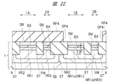
また、給電領域2Bは、pMIS形成領域1Bの半導体基板SB(特にn型半導体領域NR1)に所望の電位(電圧)を供給するために半導体層SMおよび絶縁層BXを除去した領域である。給電領域2Bにおいて、プラグPG2から、金属シリサイド層SL2(およびn型半導体領域NR3)を介してn型半導体領域NR2に所望の電位(電圧)を供給できるようになっている。このため、給電領域2BのプラグPG2から、金属シリサイド層SL2(給電領域2Bの金属シリサイド層SL2)、n型半導体領域NR3およびn型半導体領域NR2を経由して、pMIS形成領域1Bのn型半導体領域NR1に所望の電位(電圧)を供給することができる。n型半導体領域NR1の電位(電圧)を制御することにより、pMIS形成領域1Bの半導体層SMに形成されたpチャネル型MISFETQpのしきい値電圧を調整(制御)することができる。
The
<半導体装置の製造工程について>
次に、本実施の形態の半導体装置の製造工程を、図面を参照して説明する。図6および図7は、本実施の形態の半導体装置の製造工程を示す工程フロー図である。図8〜図45は、本実施の形態の半導体装置の製造工程中の要部平面図または要部断面図である。
<About semiconductor device manufacturing process>
Next, the manufacturing process of the semiconductor device of this embodiment will be described with reference to the drawings. 6 and 7 are process flowcharts showing the manufacturing process of the semiconductor device of the present embodiment. 8 to 45 are principal part plan views or principal part sectional views in the manufacturing process of the semiconductor device of the present embodiment.
図8〜図45のうち、図9、図11、図13、図15、図17、図19、図21、図25、図29、図32、図38、および図42は、上記図1に相当する領域の平面図であり、理解を簡単にするために、一部の部材にハッチングを付してある。また、図8〜図45のうち、図8、図10、図12、図14、図16、図18、図20、図22、図26、図30、図33、図35、図39、および図43は、上記図2に相当する領域の断面図であり、対応する平面図のA−A線の断面図にほぼ対応している。また、図8〜図45のうち、図23、図27、図31、図34、図36、図40、および図44は、上記図3に相当する領域の断面図であり、対応する平面図のB−B線の断面図およびC−C線の断面図にほぼ対応している。また、図8〜図45のうち、図24、図28、図37、図41、および図45は、上記図5に相当する領域の断面図であり、対応する平面図のD−D線の断面図およびE−E線の断面図にほぼ対応している。 8 to 45, FIGS. 9, 11, 13, 15, 17, 19, 21, 25, 29, 32, 38, and 42 are the same as those in FIG. 1. It is a top view of the area | region which corresponds, and in order to understand easily, a part of member is hatched. 8 to 45, FIGS. 8, 10, 12, 14, 16, 16, 18, 20, 22, 26, 30, 30, 33, 35, 39, and FIG. 43 is a cross-sectional view of a region corresponding to FIG. 2, and substantially corresponds to the cross-sectional view taken along the line AA of the corresponding plan view. 8 to 45, FIGS. 23, 27, 31, 34, 36, 40, and 44 are cross-sectional views of the region corresponding to FIG. 3 and corresponding plan views. This corresponds approximately to the cross-sectional view taken along the line BB and the cross-sectional view taken along the line CC. Also, among FIGS. 8 to 45, FIGS. 24, 28, 37, 41, and 45 are cross-sectional views of the region corresponding to FIG. It substantially corresponds to the sectional view and the sectional view taken along line EE.
まず、図8に示されるように、SOI基板1を用意する(図6のステップS1)。
First, as shown in FIG. 8, the
SOI基板1は、支持基板としての半導体基板(支持基板)SBと、半導体基板SBの主面上に形成された絶縁層(埋め込み絶縁膜)BXと、絶縁層BXの上面上に形成された半導体層SMと、を有している。
The
半導体基板SBは、絶縁層BXと絶縁層BXよりも上の構造とを支持する支持基板であるが、半導体基板でもある。半導体基板SBは、好ましくは単結晶シリコン基板であり、例えばp型の単結晶シリコンからなる。例えば、1〜10Ωcm程度の比抵抗を有する単結晶シリコンにより、半導体基板SBを形成することができる。半導体基板SBの厚みは、例えば700〜750μm程度とすることができる。絶縁層BXは、例えば酸化シリコン膜であり、絶縁層BXの厚みは、例えば膜厚10〜50nm程度とすることができる。絶縁層BXが酸化シリコン膜の場合、絶縁層BXは、埋め込み酸化膜、すなわちBOX(Buried Oxide)層とみなすこともできる。半導体層SMは、単結晶シリコンなどからなる。例えば、1〜10Ωcm程度の比抵抗を有する単結晶シリコンにより、半導体層SMを形成することができる。支持基板である半導体基板SBの厚みに比べて半導体層SMの厚みは薄く、半導体層SMの厚みは、例えば5〜20nm程度とすることができる。 The semiconductor substrate SB is a support substrate that supports the insulating layer BX and the structure above the insulating layer BX, but is also a semiconductor substrate. The semiconductor substrate SB is preferably a single crystal silicon substrate, and is made of, for example, p-type single crystal silicon. For example, the semiconductor substrate SB can be formed of single crystal silicon having a specific resistance of about 1 to 10 Ωcm. The thickness of the semiconductor substrate SB can be set to, for example, about 700 to 750 μm. The insulating layer BX is, for example, a silicon oxide film, and the thickness of the insulating layer BX can be, for example, about 10 to 50 nm. When the insulating layer BX is a silicon oxide film, the insulating layer BX can be regarded as a buried oxide film, that is, a BOX (Buried Oxide) layer. The semiconductor layer SM is made of single crystal silicon or the like. For example, the semiconductor layer SM can be formed of single crystal silicon having a specific resistance of about 1 to 10 Ωcm. The thickness of the semiconductor layer SM is smaller than the thickness of the semiconductor substrate SB that is the support substrate, and the thickness of the semiconductor layer SM can be set to about 5 to 20 nm, for example.
SOI基板1の製造方法に制限はないが、例えば、SIMOX(Silicon Implanted Oxide)法で製造することができる。SIMOX法では、シリコン(Si)からなる半導体基板の主面に高いエネルギーでO2(酸素)をイオン注入し、その後の熱処理でSi(シリコン)と酸素とを結合させ、半導体基板の表面よりも少し深い位置に酸化シリコンからなる絶縁層BXを形成する。この場合、絶縁層BX上に残存するシリコン(Si)の薄膜が半導体層SMとなり、絶縁層BX下の半導体基板が半導体基板SBとなる。また、貼り合わせ法によりSOI基板1を形成してもよい。貼り合わせ法では、例えば、シリコン(Si)からなる第1半導体基板の表面を酸化して絶縁層BXを形成した後、その第1半導体基板にシリコン(Si)からなる第2半導体基板を高温下で圧着することにより貼り合わせ、その後、第2半導体基板を薄膜化する。この場合、絶縁層BX上に残存する第2半導体基板の薄膜が半導体層SMとなり、絶縁層BX下の第1半導体基板が半導体基板SBとなる。更に他の手法、例えばスマートカット(Smart Cut)プロセスなどを用いて、SOI基板1を製造することもできる。
Although there is no restriction | limiting in the manufacturing method of
なお、SOI基板1において、半導体基板SBの主面のうち、絶縁層BXに接する側の主面を半導体基板の上面と称し、半導体基板SBの上面とは反対側の主面を、半導体基板SBの裏面と称することとする。また、SOI基板1において、絶縁層BXの主面のうち、半導体基板SBに接する側の主面を絶縁層BXの下面と称し、半導体層SMに接する側の主面を絶縁層BXの上面と称し、絶縁層の上面と下面とは、互いに反対側の面である。また、半導体層SMの主面のうち、絶縁層BXに接する側の主面を半導体層SMの下面と称し、半導体層SMの下面とは反対側の主面を、半導体層SMの上面と称する。
In the
次に、図9および図10に示されるように、SOI基板1に素子分離領域STを形成する(図6のステップS2)。 Next, as shown in FIGS. 9 and 10, an element isolation region ST is formed in the SOI substrate 1 (step S2 in FIG. 6).
なお、図9は、平面図であるが、素子分離領域STに太線の斜線のハッチングを付し、半導体層SMにドットのハッチングを付してある。また、図10は、図9のA−A線の断面図にほぼ対応している。 Although FIG. 9 is a plan view, the element isolation region ST is hatched with a thick diagonal line, and the semiconductor layer SM is hatched with a dot. FIG. 10 substantially corresponds to the cross-sectional view taken along the line AA of FIG.
ステップS1でSOI基板1を用意した段階では、半導体基板SBの上面の全面上に絶縁層BXを介して半導体層SMが形成されていたが、ステップS2で素子分離領域STを形成すると、半導体層SMは、それぞれ素子分離領域STで囲まれた複数の領域(活性領域)に区画される。
At the stage where the
素子分離領域STは、STI(shallow trench isolation)法を用いて形成することができる。具体的には、次のようにして素子分離領域STを形成することができる。 The element isolation region ST can be formed using an STI (shallow trench isolation) method. Specifically, the element isolation region ST can be formed as follows.
すなわち、まず、SOI基板1上に、すなわちSOI基板1の半導体層SM上に、絶縁膜(例えば窒化シリコン膜)を形成してから、その絶縁膜をフォトリソグラフィ法およびドライエッチング法を用いてパターニング(加工)することにより、窒化シリコン膜などからなるハードマスク層(図示せず)を形成する。それから、そのハードマスク層をエッチングマスクとして用いて、SOI基板1をエッチング(好ましくはドライエッチング)することにより、SOI基板1に素子分離溝TRを形成する。素子分離溝TRは、素子分離領域ST用の溝である。素子分離溝TRは、半導体層SMおよび絶縁層BXを貫通し、素子分離溝TRの底部が半導体基板SBに到達している(すなわち半導体基板SBの厚みの途中に素子分離溝TRの底部が位置している)ため、素子分離溝TRの底部では、半導体基板SBが露出される。それから、SOI基板1の主面上に、素子分離溝TRを埋めるように、素子分離領域ST用の絶縁膜(例えば酸化シリコン膜)を形成してから、素子分離溝TRの外部のその絶縁膜をCMP(Chemical Mechanical Polishing:化学的機械的研磨)法などを用いて除去し、その後、ハードマスク層を除去する。これにより、素子分離溝TRに埋め込まれた絶縁膜からなる素子分離領域STを形成することができる。
That is, first, after forming an insulating film (for example, a silicon nitride film) on the
素子分離領域STは、各素子、ここでは、nチャネル型MISFET(Qn)およびpチャネル型MISFET(Qp)間の干渉を防止するために形成される。素子分離領域STは、SOI基板1の複数の活性領域同士を分離する不活性領域である。素子分離領域STによって平面的に囲まれた活性領域を構成する半導体層SMに、以下に説明するようにMISFETが形成される。活性領域の平面視における形状は、素子分離領域STに囲まれることで規定されている。
The element isolation region ST is formed in order to prevent interference between the elements, here, the n-channel MISFET (Qn) and the p-channel MISFET (Qp). The element isolation region ST is an inactive region that isolates a plurality of active regions of the
素子分離領域STのうち、絶縁層BXの下面から突出する部分の長さT1(寸法)は、例えば250〜350nm程度とすることができる。すなわち、素子分離領域STの底面は、絶縁層BXの下面よりも、長さT1だけ深い位置にある。従って、長さT1は、絶縁層BXの下面からの素子分離領域STの底面の深さとみなすこともできる。なお、長さT1は、図10に示されている。 In the element isolation region ST, a length T1 (dimension) of a portion protruding from the lower surface of the insulating layer BX can be set to, for example, about 250 to 350 nm. That is, the bottom surface of the element isolation region ST is deeper than the lower surface of the insulating layer BX by the length T1. Therefore, the length T1 can be regarded as the depth of the bottom surface of the element isolation region ST from the lower surface of the insulating layer BX. The length T1 is shown in FIG.
この段階では、nMIS形成領域1A、pMIS形成領域1B、給電領域2Aおよび給電領域2Bには、それぞれ、素子分離領域STで囲まれて区画された半導体層SMが存在している。nMIS形成領域1Aの半導体層SMは、nチャネル型MISFETQnを形成するための活性領域であり、pMIS形成領域1Bの半導体層SMは、nチャネル型MISFETQnを形成するための活性領域である。nMIS形成領域1Aの半導体層SM、pMIS形成領域1Bの半導体層SM、給電領域2Aの半導体層SM、および給電領域2Bの半導体層SMのそれぞれの平面形状は、例えば矩形状とすることができる。なお、給電領域2Aの半導体層SMおよび絶縁層BXと、給電領域2Bの半導体層SMおよび絶縁層BXとは、後述のステップS9で除去される。
At this stage, the
次に、図11および図12に示されるように、SOI基板1の半導体基板SBにp型ウエルPWをイオン注入により形成する(図6のステップS3)。
Next, as shown in FIGS. 11 and 12, a p-type well PW is formed in the semiconductor substrate SB of the
なお、図11は、平面図であるが、フォトレジストパターンRP1に太線の斜線のハッチングを付し、p型ウエルPWが形成される平面領域に細線の斜線のハッチングを付してある。また、図12は、図11のA−A線の断面図にほぼ対応している。 Although FIG. 11 is a plan view, the photoresist pattern RP1 is hatched with a thick oblique line, and the planar region where the p-type well PW is formed is hatched with a thin oblique line. 12 substantially corresponds to the cross-sectional view taken along the line AA in FIG.
ステップS3において、p型ウエルPWは、SOI基板1の半導体基板SBにp型不純物(例えばホウ素)をイオン注入することにより形成される。具体的には、まず、図11および図12に示されるように、SOI基板1の主面上に、マスク層として、フォトリソグラフィ法を用いてフォトレジストパターン(マスク層)RP1を形成する。フォトレジストパターンRP1は、p型ウエルPW形成予定領域を露出し、かつ、他の領域(n型ウエルNW形成予定領域を含む)を覆うように形成される。すなわち、フォトレジストパターンRP1は、p型ウエルPW形成予定領域を露出する開口部OP1を有している。開口部OP1は、平面視でnMIS形成領域1Aおよび給電領域2Aを内包している。それから、フォトレジストパターンRP1をマスク(イオン注入阻止マスク)として用いて、SOI基板1の半導体基板SBにp型不純物(例えばホウ素)をイオン注入することにより、p型ウエルPWを形成する。p型ウエルPWは、フォトレジストパターンRP1の開口部OP1に整合して形成される。その後、フォトレジストパターンRP1を除去する。このようにして、ステップS3でp型ウエルPWが形成される。p型ウエルPWは、p型半導体領域とみなすこともできる。
In step S3, the p-type well PW is formed by ion-implanting p-type impurities (for example, boron) into the semiconductor substrate SB of the
また、ステップS3でp型ウエルPWを形成するイオン注入を行う際に、nMIS形成領域1Aおよび給電領域2Aの半導体層SMにも、p型不純物がイオン注入され得る。これにより、nMIS形成領域1Aの半導体層SM全体がp型ウエル領域となり得る。
In addition, when performing ion implantation for forming the p-type well PW in step S3, p-type impurities can also be implanted into the semiconductor layer SM in the
絶縁層BXの下面(すなわち半導体基板SBの上面)からのp型ウエルPWの底面の深さT2は、例えば2000〜2500nm程度とすることができる。なお、深さT2は、図12に示されている。ここで、深さT2は、上記長さT1よりも大きい(T2>T1)。また、p型ウエルPWの不純物濃度(p型不純物濃度)は、例えば1×10¹⁶〜5×10¹⁷/cm3程度とすることができる。 The depth T2 of the bottom surface of the p-type well PW from the lower surface of the insulating layer BX (that is, the upper surface of the semiconductor substrate SB) can be, for example, about 2000 to 2500 nm. The depth T2 is shown in FIG. Here, the depth T2 is larger than the length T1 (T2> T1). Further, the impurity concentration (p-type impurity concentration) of the p-type well PW can be set to, for example, about 1 × 10 16 to 5 × 10 17 / cm 3 .
次に、図13および図14に示されるように、SOI基板1の半導体基板SBにn型ウエルNWをイオン注入により形成する(図6のステップS4)。
Next, as shown in FIGS. 13 and 14, an n-type well NW is formed in the semiconductor substrate SB of the
なお、図13は、平面図であるが、フォトレジストパターンRP2に太線の斜線のハッチングを付し、n型ウエルNWが形成される平面領域に細線の斜線のハッチングを付してある。また、図14は、図13のA−A線の断面図にほぼ対応している。 Although FIG. 13 is a plan view, the photoresist pattern RP2 is hatched with a thick diagonal line, and the planar region where the n-type well NW is formed is hatched with a thin diagonal line. Further, FIG. 14 substantially corresponds to the cross-sectional view taken along the line AA of FIG.
ステップS4において、n型ウエルNWは、SOI基板1の半導体基板SBにn型不純物(例えばリンまたはヒ素)をイオン注入することにより形成される。具体的には、まず、図13および図14に示されるように、SOI基板1の主面上に、マスク層として、フォトリソグラフィ法を用いてフォトレジストパターン(マスク層)RP2を形成する。フォトレジストパターンRP2は、n型ウエルNW形成予定領域を露出し、かつ、他の領域(p型ウエルPW形成領域を含む)を覆うように形成される。すなわち、フォトレジストパターンRP2は、n型ウエルNW形成予定領域を露出する開口部OP2を有している。開口部OP2は、平面視でpMIS形成領域1Bおよび給電領域2Bを内包している。それから、フォトレジストパターンRP2をマスク(イオン注入阻止マスク)として用いて、SOI基板1の半導体基板SBにn型不純物(例えばリンまたはヒ素)をイオン注入することにより、n型ウエルNWを形成する。n型ウエルNWは、フォトレジストパターンRP2の開口部OP2に整合して形成される。その後、フォトレジストパターンRP2を除去する。このようにして、ステップS4でn型ウエルNWが形成される。n型ウエルNWは、n型半導体領域とみなすこともできる。
In step S4, the n-type well NW is formed by ion-implanting an n-type impurity (for example, phosphorus or arsenic) into the semiconductor substrate SB of the
また、ステップS4でn型ウエルNWを形成するイオン注入を行う際に、pMIS形成領域1Bおよび給電領域2Bの半導体層SMにも、p型不純物がイオン注入され得る。これにより、pMIS形成領域1Bの半導体層SM全体がn型ウエル領域となり得る。
In addition, when performing ion implantation for forming the n-type well NW in step S4, p-type impurities can be ion-implanted also into the semiconductor layer SM in the
絶縁層BXの下面(すなわち半導体基板SBの上面)からのn型ウエルNWの底面の深さT3は、例えば2000〜2500nm程度とすることができる。なお、深さT3は、図14に示されている。ここで、深さT3は、上記長さT1よりも大きい(T3>T1)。また、n型ウエルnWの不純物濃度(n型不純物濃度)は、例えば1×10¹⁶〜5×10¹⁷/cm3程度とすることができる。 The depth T3 of the bottom surface of the n-type well NW from the lower surface of the insulating layer BX (that is, the upper surface of the semiconductor substrate SB) can be, for example, about 2000 to 2500 nm. The depth T3 is shown in FIG. Here, the depth T3 is larger than the length T1 (T3> T1). The impurity concentration (n-type impurity concentration) of the n-type well nW can be set to, for example, about 1 × 10 16 to 5 × 10 17 / cm 3 .
なお、ここでは、先にステップS3でイオン注入によりp型ウエルPWを形成してから、ステップS4でイオン注入によりn型ウエルNWを形成する場合について説明したが、他の形態として、先にステップS4でイオン注入によりn型ウエルNWを形成してから、ステップS3でイオン注入によりp型ウエルPWを形成してもよい。 Here, the case has been described where the p-type well PW is formed by ion implantation in step S3 and then the n-type well NW is formed by ion implantation in step S4. After the n-type well NW is formed by ion implantation in S4, the p-type well PW may be formed by ion implantation in step S3.
p型ウエルPWおよびn型ウエルNWは、それぞれ、SOI基板1の半導体基板SB内に形成され、半導体基板SBの上面から所定の深さにわたって形成される。p型ウエルPWおよびn型ウエルNWのそれぞれの深さは、素子分離領域STの深さよりも深い。すなわち、p型ウエルPWおよびn型ウエルNWのそれぞれの底面の深さ位置は、素子分離領域STの底面の深さ位置よりも深い。p型ウエルPWは、平面視でnMIS形成領域1Aおよび給電領域2Aを含むように形成され、n型ウエルNWは、平面視でpMIS形成領域1Bおよび給電領域2Bを含むように形成される。半導体基板SBにおいて、p型ウエルPWとn型ウエルNWとは、互いに隣接して形成されるが、p型ウエルPWとn型ウエルNWとの境界(すなわちp型ウエルPWとn型ウエルNWとの間に形成されるpn接合面)は、素子分離領域STの下に配置される。p型ウエルPWの深さと、n型ウエルNWの深さとは、ほぼ同じとすることができる。すなわち、p型ウエルPWの底面の深さ位置と、n型ウエルNWの底面の深さ位置とは、ほぼ同じとすることができる。
The p-type well PW and the n-type well NW are each formed in the semiconductor substrate SB of the
p型ウエルPWの深さは素子分離領域STの深さよりも深いため、p型ウエルPWは、nMIS形成領域1Aおよび給電領域2Aの半導体基板SBだけでなく、素子分離領域STの下の半導体基板SBにも形成されている。このため、半導体基板SBにおいて、平面視でnMIS形成領域1Aと給電領域2Aとの間に存在する素子分離領域STの下にもp型ウエルPWが形成されている。
Since the depth of the p-type well PW is deeper than the depth of the element isolation region ST, the p-type well PW is not only the semiconductor substrate SB in the
また、n型ウエルNWの深さは素子分離領域STの深さよりも深いため、n型ウエルNWは、pMIS形成領域1Bおよび給電領域2Bの半導体基板SBだけでなく、素子分離領域STの下の半導体基板SBにも形成されている。このため、半導体基板SBにおいて、平面視でpMIS形成領域1Bと給電領域2Bとの間に存在する素子分離領域STの下にもn型ウエルNWが形成されている。
Further, since the depth of the n-type well NW is deeper than the depth of the element isolation region ST, the n-type well NW is provided not only in the semiconductor substrate SB in the
次に、図15および図16に示されるように、SOI基板1の半導体基板SBにp型半導体領域PR2をイオン注入により形成する(図6のステップS5)。
Next, as shown in FIGS. 15 and 16, a p-type semiconductor region PR2 is formed in the semiconductor substrate SB of the
なお、図15は、平面図であるが、フォトレジストパターンRP3に太線の斜線のハッチングを付し、p型半導体領域PR2が形成される平面領域に細線の斜線のハッチングを付してある。また、図16は、図15のA−A線の断面図にほぼ対応している。 Although FIG. 15 is a plan view, the photoresist pattern RP3 is hatched with a thick oblique line, and the planar region where the p-type semiconductor region PR2 is formed is hatched with a thin oblique line. 16 substantially corresponds to the cross-sectional view taken along the line AA in FIG.
ステップS5において、p型半導体領域PR2は、SOI基板1の半導体基板SBにp型不純物(例えばホウ素)をイオン注入することにより形成される。具体的には、まず、図15および図16に示されるように、SOI基板1の主面上に、マスク層として、フォトリソグラフィ法を用いてフォトレジストパターン(マスク層)RP3を形成する。フォトレジストパターンRP3は、p型半導体領域PR2形成予定領域を露出し、かつ、他の領域(pMIS形成領域1Bおよび給電領域2Bを含む)を覆うように形成される。すなわち、フォトレジストパターンRP3は、p型半導体領域PR2形成予定領域を露出する開口部OP3を有している。開口部OP3は、平面視でnMIS形成領域1Aおよび給電領域2Aを内包している。それから、フォトレジストパターンRP3をマスク(イオン注入阻止マスク)として用いて、SOI基板1の半導体基板SBにp型不純物(例えばホウ素)をイオン注入することにより、p型半導体領域PR2を形成する。p型半導体領域PR2は、フォトレジストパターンRP3の開口部OP3に整合して形成される。
In step S5, the p-type semiconductor region PR2 is formed by ion-implanting p-type impurities (for example, boron) into the semiconductor substrate SB of the
p型半導体領域PR2の不純物濃度(p型不純物濃度)は、p型ウエルPWの不純物濃度(p型不純物濃度)よりも高い。このため、p型半導体領域PR2の抵抗率(比抵抗)は、p型ウエルPWの抵抗率よりも低くなる。 The impurity concentration (p-type impurity concentration) of the p-type semiconductor region PR2 is higher than the impurity concentration (p-type impurity concentration) of the p-type well PW. For this reason, the resistivity (specific resistance) of the p-type semiconductor region PR2 is lower than the resistivity of the p-type well PW.
p型半導体領域PR2は、SOI基板1の半導体基板SB内に形成され、半導体基板SBの上面から所定の深さにわたって形成される。p型半導体領域PR2の深さは、p型ウエルPWの深さよりも浅く、かつ、素子分離領域STの深さよりも深い。すなわち、p型半導体領域PR2の底面の深さ位置は、p型ウエルPWの底面の深さ位置よりも浅く、かつ、素子分離領域STの底面の深さ位置よりも深い。
The p-type semiconductor region PR2 is formed in the semiconductor substrate SB of the
絶縁層BXの下面(すなわち半導体基板SBの上面)からのp型半導体領域PR2の底面の深さT4は、例えば1000〜1500nm程度とすることができる。なお、深さT4は、図16に示されている。ここで、深さT4は、上記長さT1よりも大きく、かつ上記深さT2よりも小さい(T1<T4<T2)。また、p型半導体領域PR2の不純物濃度(p型不純物濃度)は、p型ウエルPWの不純物濃度(p型不純物濃度)よりも高く、例えば5×10¹⁷〜1×10¹⁸/cm3程度とすることができる。 The depth T4 of the bottom surface of the p-type semiconductor region PR2 from the lower surface of the insulating layer BX (that is, the upper surface of the semiconductor substrate SB) can be, for example, about 1000 to 1500 nm. The depth T4 is shown in FIG. Here, the depth T4 is larger than the length T1 and smaller than the depth T2 (T1 <T4 <T2). Further, the impurity concentration (p-type impurity concentration) of the p-type semiconductor region PR2 is higher than the impurity concentration (p-type impurity concentration) of the p-type well PW, for example, about 5 × 10 17 to 1 × 10 18 / cm 3. can do.
p型半導体領域PR2の深さをp型ウエルPWの深さよりも浅くするため、ステップS5のイオン注入では、ステップS3よりも、注入深さを浅く設定する必要がある。これは、例えば、ステップS5のイオン注入の注入エネルギーを、ステップS3のイオン注入の注入エネルギーよりも小さくすることなどにより、実現することができる。 In order to make the depth of the p-type semiconductor region PR2 shallower than the depth of the p-type well PW, it is necessary to set the implantation depth shallower than in step S3 in the ion implantation in step S5. This can be realized, for example, by making the implantation energy of the ion implantation in step S5 smaller than the implantation energy of the ion implantation in step S3.
p型半導体領域PR2の深さは、p型ウエルPWの深さよりも浅く、かつ、素子分離領域STの深さよりも深いため、p型半導体領域PR2は、nMIS形成領域1Aおよび給電領域2Aの半導体基板SBだけでなく、素子分離領域STの下の半導体基板SBにも形成される。このため、半導体基板SBにおいて、平面視でnMIS形成領域1Aと給電領域2Aとの間に存在する素子分離領域STの下にもp型半導体領域PR2が形成され、そのp型半導体領域PR2の下にはp型ウエルPWが存在している。
Since the depth of the p-type semiconductor region PR2 is shallower than the depth of the p-type well PW and deeper than the depth of the element isolation region ST, the p-type semiconductor region PR2 is a semiconductor of the
p型半導体領域PR2は、p型ウエルPWに内包されるように形成される。このため、p型半導体領域PR2の底面全体がp型ウエルPWに接し、p型半導体領域PR2の側面は、素子分離領域STに接する部分を除き、p型ウエルPWに接している。すなわち、p型半導体領域PR2の底面と側面は、素子分離領域STに接する部分を除き、p型ウエルPWに囲まれている。p型半導体領域PR2は、p型ウエルPWに内包されるように形成されるため、平面視においてp型半導体領域PR2がp型ウエルPWに内包されるとともに、p型半導体領域PR2の底面はp型ウエルPWの底面よりも浅い位置にある。但し、p型半導体領域PR2は、平面視でnMIS形成領域1Aおよび給電領域2Aを含むように形成される。
The p-type semiconductor region PR2 is formed so as to be enclosed in the p-type well PW. Therefore, the entire bottom surface of the p-type semiconductor region PR2 is in contact with the p-type well PW, and the side surface of the p-type semiconductor region PR2 is in contact with the p-type well PW except for a portion in contact with the element isolation region ST. That is, the bottom surface and the side surface of the p-type semiconductor region PR2 are surrounded by the p-type well PW except for the portion in contact with the element isolation region ST. Since the p-type semiconductor region PR2 is formed so as to be included in the p-type well PW, the p-type semiconductor region PR2 is included in the p-type well PW in plan view, and the bottom surface of the p-type semiconductor region PR2 is p It is in a position shallower than the bottom surface of the mold well PW. However, the p-type semiconductor region PR2 is formed to include the
SOI基板1の半導体基板SBにおいて、ステップS5でp型不純物がイオン注入されてp型半導体領域PR2が形成される平面領域は、ステップS3でp型不純物がイオン注入されてp型ウエルPWが形成された平面領域に内包されている。これを実現するために、フォトレジストパターンRP3の開口部OP3の平面寸法(平面積)は、上記フォトレジストパターンRP1の開口部OP1の平面寸法(平面積)よりも小さくなっている。そして、フォトレジストパターンRP3とフォトレジストパターンRP1とを重ねた場合を仮定したときに、平面視において、フォトレジストパターンRP3の開口部OP3は、フォトレジストパターンRP1の開口部OP1に内包される。更に、上述のようにp型半導体領域PR2をp型ウエルPWよりも浅く形成することで、p型半導体領域PR2は、p型ウエルPWに内包されることになる。
In the semiconductor substrate SB of the
次に、図17および図18に示されるように、SOI基板1の半導体基板SBにp型半導体領域PR1aをイオン注入により形成する(図6のステップS6)。
Next, as shown in FIGS. 17 and 18, a p-type semiconductor region PR1a is formed in the semiconductor substrate SB of the
なお、図17は、平面図であるが、フォトレジストパターンRP3に太線の斜線のハッチングを付し、p型半導体領域PR1aが形成される平面領域に細線の斜線のハッチングを付してある。また、図18は、図17のA−A線の断面図にほぼ対応している。 Although FIG. 17 is a plan view, the photoresist pattern RP3 is hatched with a thick diagonal line, and the planar area where the p-type semiconductor region PR1a is formed is hatched with a thin diagonal line. FIG. 18 substantially corresponds to the cross-sectional view taken along the line AA of FIG.
p型半導体領域PR2の深さは、素子分離領域STの深さよりも深かったが、p型半導体領域PR1aの深さは、素子分離領域STの深さよりも浅くする。すなわち、p型半導体領域PR2の底面の深さ位置は、素子分離領域STの底面の深さ位置よりも深かったが、p型半導体領域PR1aの底面の深さ位置は、素子分離領域STの底面の深さ位置よりも浅くする。このため、ステップS6のイオン注入では、ステップS5のイオン注入よりも、注入深さを浅く設定する必要がある。これは、例えば、ステップS6のイオン注入の注入エネルギーを、ステップS5のイオン注入の注入エネルギーよりも小さくすることなどにより、実現することができる。 The depth of the p-type semiconductor region PR2 is deeper than the depth of the element isolation region ST, but the depth of the p-type semiconductor region PR1a is shallower than the depth of the element isolation region ST. That is, the depth position of the bottom surface of the p-type semiconductor region PR2 is deeper than the depth position of the bottom surface of the element isolation region ST, but the depth position of the bottom surface of the p-type semiconductor region PR1a is the bottom surface of the element isolation region ST. Make it shallower than the depth position. For this reason, in the ion implantation in step S6, it is necessary to set the implantation depth shallower than in the ion implantation in step S5. This can be realized, for example, by making the implantation energy of the ion implantation in step S6 smaller than the implantation energy of the ion implantation in step S5.
絶縁層BXの下面(すなわち半導体基板SBの上面)からのp型半導体領域PR1aの底面の深さT5は、例えば50〜150nm程度とすることができる。なお、深さT5は、図18に示されている。ここで、深さT5は、上記長さT1よりも小さく、上記深さT2よりも小さく、かつ、上記深さT4よりも小さい(T5<T1、T5<T2かつT5<T4)。また、p型半導体領域PR1aの不純物濃度(p型不純物濃度)は、p型半導体領域PR2の不純物濃度(p型不純物濃度)よりも高く、例えば2×10¹⁸〜1×10²⁰/cm3程度とすることができる。 The depth T5 of the bottom surface of the p-type semiconductor region PR1a from the lower surface of the insulating layer BX (that is, the upper surface of the semiconductor substrate SB) can be, for example, about 50 to 150 nm. The depth T5 is shown in FIG. Here, the depth T5 is smaller than the length T1, smaller than the depth T2, and smaller than the depth T4 (T5 <T1, T5 <T2 and T5 <T4). Further, the impurity concentration (p-type impurity concentration) of the p-type semiconductor region PR1a is higher than the impurity concentration (p-type impurity concentration) of the p-type semiconductor region PR2, for example, about 2 × 10 18 to 1 × 10 20 / cm 3. It can be.
ステップS6において、p型半導体領域PR1aは、SOI基板1の半導体基板SBにp型不純物(例えばホウ素)をイオン注入することにより形成される。具体的には、図17および図18に示されるように、SOI基板1の主面上に上記ステップS5で使用したフォトレジストパターンRP3が形成されている状態で、そのフォトレジストパターンRP3をマスク(イオン注入阻止マスク)として用いて、SOI基板1の半導体基板SBにp型不純物(例えばホウ素)をイオン注入することにより、p型半導体領域PR1aを形成する。すなわち、同じフォトレジストパターンRP3をマスク(イオン注入阻止マスク)として用いて、ステップS5のイオン注入とステップS6のイオン注入とを行うことができる。ステップS5のイオン注入とステップS6のイオン注入とを行った後に、フォトレジストパターンRP3は除去される。
In step S6, the p-type semiconductor region PR1a is formed by ion-implanting p-type impurities (for example, boron) into the semiconductor substrate SB of the
上述のように、p型半導体領域PR1aとp型半導体領域PR2とは、同じフォトレジストパターンRP3をマスクとして用いて、異なるイオン注入によって形成し、p型半導体領域PR2は素子分離領域STよりも深く、p型半導体領域PR1aは素子分離領域STよりも浅く形成する。このため、p型半導体領域PR1aは、平面視において、p型半導体領域PR2が形成されている領域のうち、素子分離領域STが形成されていない領域に形成される。フォトレジストパターンRP3の開口部OP3は、平面視でnMIS形成領域1Aおよび給電領域2Aを内包しているため、nMIS形成領域1Aおよび給電領域2Aにおける半導体基板SBの表層部分にp型半導体領域PR1aが形成される。
As described above, the p-type semiconductor region PR1a and the p-type semiconductor region PR2 are formed by different ion implantations using the same photoresist pattern RP3 as a mask, and the p-type semiconductor region PR2 is deeper than the element isolation region ST. The p-type semiconductor region PR1a is formed shallower than the element isolation region ST. Therefore, the p-type semiconductor region PR1a is formed in a region where the element isolation region ST is not formed in the region where the p-type semiconductor region PR2 is formed in plan view. Since the opening OP3 of the photoresist pattern RP3 includes the
p型半導体領域PR1aは、nMIS形成領域1Aおよび給電領域2Aにおける半導体基板SBの表層部分に形成されるため、nMIS形成領域1Aにおいて、p型半導体領域PR2の上部(表層部)にp型半導体領域PR1aが形成され、給電領域2Aにおいて、p型半導体領域PR2の上部(表層部)にp型半導体領域PR1aが形成されることになる。p型半導体領域PR1aは、素子分離領域STよりも浅く形成されるため、素子分離領域STの下にはp型半導体領域PR1aは形成されない。このため、nMIS形成領域1Aに形成されたp型半導体領域PR1aと給電領域2Aに形成されたp型半導体領域PR1aとは、繋がっておらず、素子分離領域STによって分離されている。
Since the p-type semiconductor region PR1a is formed in the surface layer portion of the semiconductor substrate SB in the
ここで、nMIS形成領域1Aの半導体基板SBに形成されたp型半導体領域PR1aを、符号PR1を付してp型半導体領域PR1と称し、給電領域2Aの半導体基板SBに形成されたp型半導体領域PR1aを、符号PR3を付してp型半導体領域PR3と称する。すなわち、ステップS6では、同じイオン注入工程により、nMIS形成領域1Aの半導体基板SBにp型半導体領域PR1が形成され、給電領域2Aの半導体基板SBにp型半導体領域PR3が形成される。
Here, the p-type semiconductor region PR1a formed on the semiconductor substrate SB in the
p型半導体領域PR1a(すなわちp型半導体領域PR1,PR3)の不純物濃度(p型不純物濃度)は、p型半導体領域PR2の不純物濃度(p型不純物濃度)よりも高い。このため、p型半導体領域PR1a(すなわちp型半導体領域PR1,PR3)の抵抗率は、p型半導体領域PR2の抵抗率よりも低い。p型半導体領域PR1の不純物濃度(p型不純物濃度)とp型半導体領域PR3の不純物濃度(p型不純物濃度)とは、ほぼ同程度である。 The impurity concentration (p-type impurity concentration) of the p-type semiconductor region PR1a (that is, the p-type semiconductor regions PR1 and PR3) is higher than the impurity concentration (p-type impurity concentration) of the p-type semiconductor region PR2. For this reason, the resistivity of the p-type semiconductor region PR1a (that is, the p-type semiconductor regions PR1 and PR3) is lower than the resistivity of the p-type semiconductor region PR2. The impurity concentration of the p-type semiconductor region PR1 (p-type impurity concentration) and the impurity concentration of the p-type semiconductor region PR3 (p-type impurity concentration) are substantially the same.
平面視でp型半導体領域PR1の周囲は素子分離領域STで囲まれており、p型半導体領域PR1の側面は素子分離領域STに接し、p型半導体領域PR1の上面は絶縁層BXに接し、p型半導体領域PR1の底面はp型半導体領域PR2に接している。すなわち、p型半導体領域PR1の側面は素子分離領域STによって囲まれており、p型半導体領域PR1の底面はp型半導体領域PR2で覆われている。また、平面視でp型半導体領域PR3の周囲は素子分離領域STで囲まれており、p型半導体領域PR3の側面は素子分離領域STに接し、p型半導体領域PR1の上面は絶縁層BXに接し、p型半導体領域PR3の底面はp型半導体領域PR2に接している。すなわち、p型半導体領域PR3の側面は素子分離領域STによって囲まれており、p型半導体領域PR3の底面はp型半導体領域PR2で覆われている。p型半導体領域PR1の底面の深さ位置と、p型半導体領域PR3の底面の深さ位置とは、ほぼ同じであるが、上述のように、素子分離領域STの底面の深さ位置よりも浅い。 In plan view, the periphery of the p-type semiconductor region PR1 is surrounded by the element isolation region ST, the side surface of the p-type semiconductor region PR1 is in contact with the element isolation region ST, and the upper surface of the p-type semiconductor region PR1 is in contact with the insulating layer BX. The bottom surface of the p-type semiconductor region PR1 is in contact with the p-type semiconductor region PR2. That is, the side surface of the p-type semiconductor region PR1 is surrounded by the element isolation region ST, and the bottom surface of the p-type semiconductor region PR1 is covered with the p-type semiconductor region PR2. In plan view, the periphery of the p-type semiconductor region PR3 is surrounded by the element isolation region ST, the side surface of the p-type semiconductor region PR3 is in contact with the element isolation region ST, and the upper surface of the p-type semiconductor region PR1 is in contact with the insulating layer BX. The bottom surface of the p-type semiconductor region PR3 is in contact with the p-type semiconductor region PR2. That is, the side surface of the p-type semiconductor region PR3 is surrounded by the element isolation region ST, and the bottom surface of the p-type semiconductor region PR3 is covered with the p-type semiconductor region PR2. The depth position of the bottom surface of the p-type semiconductor region PR1 and the depth position of the bottom surface of the p-type semiconductor region PR3 are substantially the same, but as described above, the depth position of the bottom surface of the element isolation region ST. shallow.
ステップS3,S5,S6でp型ウエルPW、p型半導体領域PR2、およびp型半導体領域PR1a(PR1,PR3)を形成すると、nMIS形成領域1Aでは、半導体基板SBの表層部分にp型半導体領域PR1が形成され、そのp型半導体領域PR1の下にp型半導体領域PR2が存在し、そのp型半導体領域PR2の下にp型ウエルPWが存在した状態になる。また、給電領域2Aでは、半導体基板SBの表層部分にp型半導体領域PR3が形成され、そのp型半導体領域PR3の下にp型半導体領域PR2が存在し、そのp型半導体領域PR2の下にp型ウエルPWが存在した状態になる。また、平面視でnMIS形成領域1Aと給電領域2Aとの間に存在する素子分離領域STの下には、p型半導体領域PR2が存在し、そのp型半導体領域PR2の下にp型ウエルPWが存在した状態になる。
When the p-type well PW, the p-type semiconductor region PR2, and the p-type semiconductor region PR1a (PR1, PR3) are formed in steps S3, S5, and S6, the p-type semiconductor region is formed on the surface layer portion of the semiconductor substrate SB in the
次に、図19および図20に示されるように、SOI基板1の半導体基板SBにn型半導体領域NR2をイオン注入により形成する(図6のステップS7)。
Next, as shown in FIGS. 19 and 20, an n-type semiconductor region NR2 is formed in the semiconductor substrate SB of the
なお、図19は、平面図であるが、フォトレジストパターンRP4に太線の斜線のハッチングを付し、n型半導体領域NR2が形成される平面領域に細線の斜線のハッチングを付してある。また、図20は、図19のA−A線の断面図にほぼ対応している。 Although FIG. 19 is a plan view, the photoresist pattern RP4 is hatched with a thick oblique line, and the planar region where the n-type semiconductor region NR2 is formed is hatched with a thin oblique line. 20 substantially corresponds to the cross-sectional view taken along the line AA of FIG.
ステップS7において、n型半導体領域NR2は、SOI基板1の半導体基板SBにn型不純物(例えばリンまたはヒ素)をイオン注入することにより形成される。具体的には、まず、図19および図20に示されるように、SOI基板1の主面上に、マスク層として、フォトリソグラフィ法を用いてフォトレジストパターン(マスク層)RP4を形成する。フォトレジストパターンRP4は、n型半導体領域NR2形成予定領域を露出し、かつ、他の領域(nMIS形成領域1Aおよび給電領域2Aを含む)を覆うように形成される。すなわち、フォトレジストパターンRP4は、n型半導体領域NR2形成予定領域を露出する開口部OP4を有している。開口部OP4は、平面視でpMIS形成領域1Bおよび給電領域2Bを内包している。それから、フォトレジストパターンRP4をマスク(イオン注入阻止マスク)として用いて、SOI基板1の半導体基板SBにn型不純物(例えばリンまたはヒ素)をイオン注入することにより、n型半導体領域NR2を形成する。n型半導体領域NR2は、フォトレジストパターンRP4の開口部OP4に整合して形成される。
In step S7, the n-type semiconductor region NR2 is formed by ion-implanting n-type impurities (for example, phosphorus or arsenic) into the semiconductor substrate SB of the
n型半導体領域NR2の不純物濃度(n型不純物濃度)は、n型ウエルNWの不純物濃度(n型不純物濃度)よりも高い。このため、n型半導体領域NR2の抵抗率(比抵抗)は、n型ウエルNWの抵抗率よりも低い。 The impurity concentration (n-type impurity concentration) of the n-type semiconductor region NR2 is higher than the impurity concentration (n-type impurity concentration) of the n-type well NW. For this reason, the resistivity (specific resistance) of the n-type semiconductor region NR2 is lower than the resistivity of the n-type well NW.
n型半導体領域NR2は、SOI基板1の半導体基板SB内に形成され、半導体基板SBの上面から所定の深さにわたって形成される。n型半導体領域NR2の深さは、n型ウエルNWの深さよりも浅く、かつ、素子分離領域STの深さよりも深い。すなわち、n型半導体領域NR2の底面の深さ位置は、n型ウエルNWの底面の深さ位置よりも浅く、かつ、素子分離領域STの底面の深さ位置よりも深い。
The n-type semiconductor region NR2 is formed in the semiconductor substrate SB of the
絶縁層BXの下面(すなわち半導体基板SBの上面)からのn型半導体領域NR2の底面の深さT6は、例えば1000〜1500nm程度とすることができる。なお、深さT6は、図20に示されている。ここで、深さT6は、上記長さT1よりも大きく、かつ上記深さT3よりも小さい(T1<T6<T3)。また、n型半導体領域NR2の不純物濃度(n型不純物濃度)は、n型ウエルNWの不純物濃度(n型不純物濃度)よりも高く、例えば5×10¹⁷〜1×10¹⁸/cm3程度とすることができる。 The depth T6 of the bottom surface of the n-type semiconductor region NR2 from the lower surface of the insulating layer BX (that is, the upper surface of the semiconductor substrate SB) can be, for example, about 1000 to 1500 nm. The depth T6 is shown in FIG. Here, the depth T6 is larger than the length T1 and smaller than the depth T3 (T1 <T6 <T3). Further, the impurity concentration (n-type impurity concentration) of the n-type semiconductor region NR2 is higher than the impurity concentration (n-type impurity concentration) of the n-type well NW, for example, about 5 × 10 17 to 1 × 10 18 / cm 3. can do.
n型半導体領域NR2の深さをn型ウエルNWの深さよりも浅くするため、ステップS7のイオン注入では、ステップS4よりも、注入深さを浅く設定する必要がある。これは、例えば、ステップS7のイオン注入の注入エネルギーを、ステップS4のイオン注入の注入エネルギーよりも小さくすることなどにより、実現することができる。 In order to make the depth of the n-type semiconductor region NR2 shallower than the depth of the n-type well NW, it is necessary to set the implantation depth shallower than in step S4 in the ion implantation in step S7. This can be realized, for example, by making the implantation energy of the ion implantation in step S7 smaller than the implantation energy of the ion implantation in step S4.
n型半導体領域NR2の深さは、n型ウエルNWの深さよりも浅く、かつ、素子分離領域STの深さよりも深いため、n型半導体領域NR2は、pMIS形成領域1Bおよび給電領域2Bの半導体基板SBだけでなく、素子分離領域STの下の半導体基板SBにも形成される。このため、半導体基板SBにおいて、平面視でpMIS形成領域1Bと給電領域2Bとの間に存在する素子分離領域STの下にもn型半導体領域NR2が形成され、そのn型半導体領域NR2の下にはn型ウエルNWが存在している。
Since the depth of the n-type semiconductor region NR2 is shallower than the depth of the n-type well NW and deeper than the element isolation region ST, the n-type semiconductor region NR2 is a semiconductor in the
n型半導体領域NR2は、n型ウエルNWに内包されるように形成される。このため、n型半導体領域NR2の底面全体がn型ウエルNWに接し、n型半導体領域NR2の側面は、素子分離領域STに接する部分を除き、n型ウエルNWに接している。すなわち、n型半導体領域NR2の底面と側面は、素子分離領域STに接する部分を除き、n型ウエルNWに囲まれている。n型半導体領域NR2は、n型ウエルNWに内包されるように形成されるため、平面視においてn型半導体領域NR2がn型ウエルNWに内包されるとともに、n型半導体領域NR2の底面はn型ウエルNWの底面よりも浅い位置にある。但し、n型半導体領域NR2は、平面視でpMIS形成領域1Bおよび給電領域2Bを含むように形成される。
The n-type semiconductor region NR2 is formed so as to be enclosed in the n-type well NW. For this reason, the entire bottom surface of the n-type semiconductor region NR2 is in contact with the n-type well NW, and the side surface of the n-type semiconductor region NR2 is in contact with the n-type well NW except for the portion in contact with the element isolation region ST. That is, the bottom surface and the side surface of the n-type semiconductor region NR2 are surrounded by the n-type well NW except for the portion in contact with the element isolation region ST. Since the n-type semiconductor region NR2 is formed so as to be included in the n-type well NW, the n-type semiconductor region NR2 is included in the n-type well NW in plan view, and the bottom surface of the n-type semiconductor region NR2 is n It is in a position shallower than the bottom surface of the mold well NW. However, the n-type semiconductor region NR2 is formed to include the
SOI基板1の半導体基板SBにおいて、ステップS7でn型不純物がイオン注入されてn型半導体領域NR2が形成される平面領域は、ステップS4でn型不純物がイオン注入されてn型ウエルNWが形成された平面領域に内包されている。これを実現するために、フォトレジストパターンRP4の開口部OP4の平面寸法(平面積)は、上記フォトレジストパターンRP2の開口部OP2の平面寸法(平面積)よりも小さくなっている。そして、フォトレジストパターンRP4とフォトレジストパターンRP2とを重ねた場合を仮定したときに、平面視において、フォトレジストパターンRP4の開口部OP4は、フォトレジストパターンRP2の開口部OP2に内包される。更に、上述のようにn型半導体領域NR2をn型ウエルNWよりも浅く形成することで、n型半導体領域NR2は、n型ウエルNWに内包されることになる。
In the semiconductor substrate SB of the
次に、図21〜図24に示されるように、SOI基板1の半導体基板SBにn型半導体領域NR1aをイオン注入により形成する(図6のステップS8)。
Next, as shown in FIGS. 21 to 24, an n-type semiconductor region NR1a is formed in the semiconductor substrate SB of the
なお、図21は、平面図であるが、フォトレジストパターンRP4に太線の斜線のハッチングを付し、n型半導体領域NR1aが形成される平面領域に細線の斜線のハッチングを付してある。また、図22は、図21のA−A線の断面図にほぼ対応し、図23は、図21のB−B線の断面図(図23の左側)および図21のC−C線の断面図(図23の右側)にほぼ対応し、図24は、図21のD−D線の断面図(図24の左側)および図21のE−E線の断面図(図24の右側)にほぼ対応している。 Although FIG. 21 is a plan view, the photoresist pattern RP4 is hatched with a thick diagonal line, and the planar area where the n-type semiconductor region NR1a is formed is hatched with a thin diagonal line. 22 substantially corresponds to the cross-sectional view taken along the line AA of FIG. 21, and FIG. 23 is a cross-sectional view taken along the line BB of FIG. 21 (left side of FIG. 23) and the line CC of FIG. 24 substantially corresponds to the cross-sectional view (right side of FIG. 23). FIG. 24 is a cross-sectional view taken along line DD in FIG. 21 (left side in FIG. 24) and cross-sectional view taken along line EE in FIG. Almost corresponds to.
n型半導体領域NR2の深さは、素子分離領域STの深さよりも深かったが、n型半導体領域NR1aの深さは、素子分離領域STの深さよりも浅くする。すなわち、n型半導体領域NR2の底面の深さ位置は、素子分離領域STの底面の深さ位置よりも深かったが、n型半導体領域NR1aの底面の深さ位置は、素子分離領域STの底面の深さ位置よりも浅くする。このため、ステップS8のイオン注入では、ステップS7のイオン注入よりも、注入深さを浅く設定する必要がある。これは、例えば、ステップS8のイオン注入の注入エネルギーを、ステップS7のイオン注入の注入エネルギーよりも小さくすることなどにより、実現することができる。 The n-type semiconductor region NR2 is deeper than the element isolation region ST, but the n-type semiconductor region NR1a is shallower than the element isolation region ST. That is, the depth position of the bottom surface of the n-type semiconductor region NR2 is deeper than the depth position of the bottom surface of the element isolation region ST, but the depth position of the bottom surface of the n-type semiconductor region NR1a is the bottom surface of the element isolation region ST. Make it shallower than the depth position. For this reason, in the ion implantation in step S8, it is necessary to set the implantation depth shallower than in the ion implantation in step S7. This can be realized, for example, by making the implantation energy of the ion implantation in step S8 smaller than the implantation energy of the ion implantation in step S7.
絶縁層BXの下面(すなわち半導体基板SBの上面)からのn型半導体領域NR1aの底面の深さT7は、例えば50〜150nm程度とすることができる。なお、深さT7は、図22に示されている。ここで、深さT7は、上記長さT1よりも小さく、上記深さT3よりも小さく、かつ、上記深さT6よりも小さい(T7<T1、T7<T3かつT7<T6)。また、n型半導体領域NR1aの不純物濃度(p型不純物濃度)は、n型半導体領域NR2の不純物濃度(n型不純物濃度)よりも高く、例えば2×10¹⁸〜1×10²⁰/cm3程度とすることができる。 A depth T7 of the bottom surface of the n-type semiconductor region NR1a from the lower surface of the insulating layer BX (that is, the upper surface of the semiconductor substrate SB) can be, for example, about 50 to 150 nm. The depth T7 is shown in FIG. Here, the depth T7 is smaller than the length T1, smaller than the depth T3, and smaller than the depth T6 (T7 <T1, T7 <T3 and T7 <T6). Further, the impurity concentration (p-type impurity concentration) of the n-type semiconductor region NR1a is higher than the impurity concentration (n-type impurity concentration) of the n-type semiconductor region NR2, for example, about 2 × 10 18 to 1 × 10 20 / cm 3. It can be.
ステップS8において、n型半導体領域NR1aは、SOI基板1の半導体基板SBにn型不純物(例えばリンまたはヒ素)をイオン注入することにより形成される。具体的には、図21〜図24に示されるように、SOI基板1の主面上に、上記ステップS7で使用したフォトレジストパターンRP4が形成されている状態で、そのフォトレジストパターンRP4をマスク(イオン注入阻止マスク)として用いて、SOI基板1の半導体基板SBにn型不純物(例えばリンまたはヒ素)をイオン注入することにより、n型半導体領域NR1aを形成する。すなわち、同じフォトレジストパターンRP4をマスク(イオン注入阻止マスク)として用いて、ステップS7のイオン注入とステップS8のイオン注入とを行うことができる。ステップS7のイオン注入とステップS8のイオン注入とを行った後に、フォトレジストパターンRP4は除去される。
In step S8, the n-type semiconductor region NR1a is formed by ion-implanting an n-type impurity (for example, phosphorus or arsenic) into the semiconductor substrate SB of the
上述のように、n型半導体領域NR1aとn型半導体領域NR2とは、同じフォトレジストパターンRP4をマスクとして用いて、異なるイオン注入によって形成し、n型半導体領域NR2は素子分離領域STよりも深く、n型半導体領域NR1aは素子分離領域STよりも浅く形成する。このため、n型半導体領域NR1aは、平面視において、n型半導体領域NR2が形成されている領域のうち、素子分離領域STが形成されていない領域に形成される。フォトレジストパターンRP4の開口部OP4は、平面視でpMIS形成領域1Bおよび給電領域2Bを内包しているため、pMIS形成領域1Bおよび給電領域2Bにおける半導体基板SBの表層部分にn型半導体領域NR1aが形成される。
As described above, the n-type semiconductor region NR1a and the n-type semiconductor region NR2 are formed by different ion implantations using the same photoresist pattern RP4 as a mask, and the n-type semiconductor region NR2 is deeper than the element isolation region ST. The n-type semiconductor region NR1a is formed shallower than the element isolation region ST. Therefore, the n-type semiconductor region NR1a is formed in a region where the element isolation region ST is not formed in the region where the n-type semiconductor region NR2 is formed in plan view. Since the opening OP4 of the photoresist pattern RP4 includes the
n型半導体領域NR1aは、pMIS形成領域1Bおよび給電領域2Bにおける半導体基板SBの表層部分に形成されるため、pMIS形成領域1Bにおいて、n型半導体領域NR2の上部(表層部)にn型半導体領域NR1aが形成され、給電領域2Bにおいて、n型半導体領域NR2の上部(表層部)にn型半導体領域NR1aが形成されることになる。n型半導体領域NR1aは、素子分離領域STよりも浅く形成されるため、素子分離領域STの下にはn型半導体領域NR1aは形成されない。このため、pMIS形成領域1Bに形成されたn型半導体領域NR1aと給電領域2Bに形成されたn型半導体領域NR1aとは、繋がっておらず、素子分離領域STによって分離されている。
Since the n-type semiconductor region NR1a is formed in the surface layer portion of the semiconductor substrate SB in the
ここで、pMIS形成領域1Bの半導体基板SBに形成されたn型半導体領域NR1aを、符号NR1を付してn型半導体領域NR1と称し、給電領域2Bの半導体基板SBに形成されたn型半導体領域NR1aを、符号NR3を付してn型半導体領域NR3と称する。すなわち、ステップS8では、同じイオン注入工程により、pMIS形成領域1Bの半導体基板SBにn型半導体領域NR1が形成され、給電領域2Bの半導体基板SBにn型半導体領域NR3が形成される。
Here, the n-type semiconductor region NR1a formed on the semiconductor substrate SB in the
n型半導体領域NR1a(すなわちn型半導体領域NR1,NR3)の不純物濃度(n型不純物濃度)は、n型半導体領域NR2の不純物濃度(n型不純物濃度)よりも高い。このため、n型半導体領域NR1a(すなわちn型半導体領域NR1,NR3)の抵抗率は、n型半導体領域NR2の抵抗率よりも低い。n型半導体領域NR1の不純物濃度(n型不純物濃度)とn型半導体領域NR3の不純物濃度(n型不純物濃度)とは、ほぼ同程度である。 The impurity concentration (n-type impurity concentration) of the n-type semiconductor region NR1a (that is, the n-type semiconductor regions NR1 and NR3) is higher than the impurity concentration (n-type impurity concentration) of the n-type semiconductor region NR2. For this reason, the resistivity of the n-type semiconductor region NR1a (that is, the n-type semiconductor regions NR1 and NR3) is lower than the resistivity of the n-type semiconductor region NR2. The impurity concentration (n-type impurity concentration) of the n-type semiconductor region NR1 and the impurity concentration (n-type impurity concentration) of the n-type semiconductor region NR3 are substantially the same.
平面視でn型半導体領域NR1の周囲は素子分離領域STで囲まれており、n型半導体領域NR1の側面は素子分離領域STに接し、n型半導体領域NR1の上面は絶縁層BXに接し、n型半導体領域NR1の底面はn型半導体領域NR2に接している。すなわち、n型半導体領域NR1の側面は素子分離領域STによって囲まれており、n型半導体領域NR1の底面はn型半導体領域NR2で覆われている。また、平面視でn型半導体領域NR3の周囲は素子分離領域STで囲まれており、n型半導体領域NR3の側面は素子分離領域STに接し、n型半導体領域NR1の上面は絶縁層BXに接し、n型半導体領域NR3の底面はn型半導体領域NR2に接している。すなわち、n型半導体領域NR3の側面は素子分離領域STによって囲まれており、n型半導体領域NR3の底面はn型半導体領域NR2で覆われている。n型半導体領域NR1の底面の深さ位置と、n型半導体領域NR3の底面の深さ位置とは、ほぼ同じであるが、上述のように、素子分離領域STの底面の深さ位置よりも浅い。 In plan view, the periphery of the n-type semiconductor region NR1 is surrounded by the element isolation region ST, the side surface of the n-type semiconductor region NR1 is in contact with the element isolation region ST, and the upper surface of the n-type semiconductor region NR1 is in contact with the insulating layer BX. The bottom surface of the n-type semiconductor region NR1 is in contact with the n-type semiconductor region NR2. That is, the side surface of the n-type semiconductor region NR1 is surrounded by the element isolation region ST, and the bottom surface of the n-type semiconductor region NR1 is covered with the n-type semiconductor region NR2. In plan view, the periphery of the n-type semiconductor region NR3 is surrounded by the element isolation region ST, the side surface of the n-type semiconductor region NR3 is in contact with the element isolation region ST, and the upper surface of the n-type semiconductor region NR1 is in contact with the insulating layer BX. The bottom surface of the n-type semiconductor region NR3 is in contact with the n-type semiconductor region NR2. That is, the side surface of the n-type semiconductor region NR3 is surrounded by the element isolation region ST, and the bottom surface of the n-type semiconductor region NR3 is covered with the n-type semiconductor region NR2. The depth position of the bottom surface of the n-type semiconductor region NR1 and the depth position of the bottom surface of the n-type semiconductor region NR3 are substantially the same, but as described above, the depth position of the bottom surface of the element isolation region ST. shallow.
ステップS4,S7,S8でn型ウエルNW、n型半導体領域NR2、およびn型半導体領域NR1a(NR1,NR3)を形成すると、pMIS形成領域1Bでは、半導体基板SBの表層部分にn型半導体領域NR1が形成され、そのn型半導体領域NR1の下にn型半導体領域NR2が存在し、そのn型半導体領域NR2の下にn型ウエルNWが存在した状態になる。また、給電領域2Bでは、半導体基板SBの表層部分にn型半導体領域NR3が形成され、そのn型半導体領域NR3の下にn型半導体領域NR2が存在し、そのn型半導体領域NR2の下にn型ウエルNWが存在した状態になる。また、平面視でpMIS形成領域1Bと給電領域2Bとの間に存在する素子分離領域STの下には、n型半導体領域NR2が存在し、そのn型半導体領域NR2の下にn型ウエルNWが存在した状態になる。
When the n-type well NW, the n-type semiconductor region NR2, and the n-type semiconductor region NR1a (NR1, NR3) are formed in steps S4, S7, and S8, the n-type semiconductor region is formed in the surface layer portion of the semiconductor substrate SB in the
なお、ここでは、ステップS5,S6でp型半導体領域PR2およびp型半導体領域PR1aを形成してから、ステップS7,S8でn型半導体領域NR2およびn型半導体領域NR1aを形成した場合について説明した。他の形態として、ステップS7,S8でn型半導体領域NR2およびn型半導体領域NR1aを形成してから、ステップS5,S6でp型半導体領域PR2およびp型半導体領域PR1aを形成することもできる。 Here, the case where the p-type semiconductor region PR2 and the p-type semiconductor region PR1a are formed in steps S5 and S6 and then the n-type semiconductor region NR2 and the n-type semiconductor region NR1a are formed in steps S7 and S8 has been described. . As another form, after forming the n-type semiconductor region NR2 and the n-type semiconductor region NR1a in steps S7 and S8, the p-type semiconductor region PR2 and the p-type semiconductor region PR1a can be formed in steps S5 and S6.
次に、図25〜図28に示されるように、給電領域2A,2Bの半導体層SMおよび絶縁層BXを除去する(図7のステップS9)。
Next, as shown in FIGS. 25 to 28, the semiconductor layer SM and the insulating layer BX in the
なお、図25は、平面図であるが、素子分離領域STに太線の斜線のハッチングを付し、半導体層SMにドットのハッチングを付し、半導体基板SBの露出領域に細線の斜線のハッチングを付してある。また、図26は、図25のA−A線の断面図にほぼ対応し、図27は、図25のB−B線の断面図(図27の左側)および図25のC−C線の断面図(図27の右側)にほぼ対応し、図28は、図25のD−D線の断面図(図28の左側)および図25のE−E線の断面図(図28の右側)にほぼ対応している。 Although FIG. 25 is a plan view, the element isolation region ST is hatched with a thick diagonal line, the semiconductor layer SM is hatched with a dot, and the exposed area of the semiconductor substrate SB is hatched with a thin line. It is attached. 26 substantially corresponds to the cross-sectional view taken along the line AA in FIG. 25, and FIG. 27 shows the cross-sectional view taken along the line BB in FIG. 25 (left side in FIG. 27) and the line CC in FIG. 28 substantially corresponds to the cross-sectional view (right side of FIG. 27), and FIG. 28 is a cross-sectional view taken along line DD of FIG. 25 (left side of FIG. 28) and cross-sectional view taken along line EE of FIG. Almost corresponds to.
ステップS9は、例えば次のようにして行うことができる。すなわち、給電領域2A,2Bを露出し、それ以外の領域を覆うようなフォトレジスト層(図示せず)を、フォトリソグラフィ法を用いてSOI基板1の主面上に形成してから、そのフォトレジスト層をエッチングマスクとして用いて、給電領域2A,2Bの半導体層SMおよび絶縁層BXをエッチングして除去する。その後、そのフォトレジスト層は除去する。これにより、図25〜図28に示されるように、SOI基板1において、給電領域2A,2Bの半導体層SMおよび絶縁層BXを選択的に除去することができる。給電領域2A,2Bでは、半導体層SMおよび絶縁層BXが除去されたことで、半導体基板SB(の上面)が露出される。具体的には、給電領域2Aでは、p型半導体領域PR3の表面(上面)が露出され、給電領域2Bでは、n型半導体領域NR3の表面(上面)が露出される。
Step S9 can be performed as follows, for example. That is, a photoresist layer (not shown) that exposes the
また、本実施の形態では、p型ウエルPW、n型ウエルNW、p型半導体領域PR2、p型半導体領域PR1a(PR1,PR3)、n型半導体領域NR2、およびn型半導体領域NR1a(NR1,NR3)をそれぞれイオン注入で形成してから、ステップS9で給電領域2A,2Bの半導体層SMおよび絶縁層BXを除去している。他の形態として、ステップS2で素子分離領域STを形成した後に、ステップS9を行って給電領域2A,2Bの半導体層SMおよび絶縁層BXを除去してから、p型ウエルPW、n型ウエルNW、p型半導体領域PR2、p型半導体領域PR1a(PR1,PR3)、n型半導体領域NR2、およびn型半導体領域NR1a(NR1,NR3)をそれぞれイオン注入で形成することもできる。
In the present embodiment, the p-type well PW, the n-type well NW, the p-type semiconductor region PR2, the p-type semiconductor region PR1a (PR1, PR3), the n-type semiconductor region NR2, and the n-type semiconductor region NR1a (NR1, NR3) is formed by ion implantation, and the semiconductor layer SM and the insulating layer BX in the
また、p型ウエルPW、n型ウエルNW、p型半導体領域PR2、p型半導体領域PR1a、n型半導体領域NR2、およびn型半導体領域NR1aを形成するための各イオン注入は、ステップS2で素子分離領域STを形成した後で、かつ、後述のステップS10,S11でMISFET(Qn,Qp)を形成する前に行う必要がある。また、ステップS9は、ステップS2で素子分離領域STを形成した後で、かつ、後述のステップS10,S11でMISFET(Qn,Qp)を形成する前に行う必要がある。 Each ion implantation for forming the p-type well PW, the n-type well NW, the p-type semiconductor region PR2, the p-type semiconductor region PR1a, the n-type semiconductor region NR2, and the n-type semiconductor region NR1a is performed in step S2. It is necessary to carry out after forming the isolation region ST and before forming MISFETs (Qn, Qp) in steps S10 and S11 described later. Further, step S9 needs to be performed after forming the element isolation region ST in step S2 and before forming MISFETs (Qn, Qp) in steps S10 and S11 described later.
次に、図29〜図31に示されるように、nMIS形成領域1Aにおける半導体層SM上にゲート絶縁膜GIを介してゲート電極GE1を形成し、pMIS形成領域1Bにおける半導体層SM上にゲート絶縁膜GIを介してゲート電極GE2を形成する(図7のステップS10)。
Next, as shown in FIGS. 29 to 31, the gate electrode GE1 is formed on the semiconductor layer SM in the
なお、図29は、平面図であるが、ゲート電極GE1,GE2に細線の斜線のハッチングを付してある。また、図30は、図29のA−A線の断面図にほぼ対応し、図31は、図29のB−B線の断面図(図31の左側)および図29のC−C線の断面図(図31の右側)にほぼ対応している。 FIG. 29 is a plan view, but the gate electrodes GE1 and GE2 are hatched with thin diagonal lines. 30 substantially corresponds to the cross-sectional view taken along the line AA in FIG. 29, and FIG. 31 is a cross-sectional view taken along the line BB in FIG. 29 (left side in FIG. 31) and the line CC in FIG. It almost corresponds to the sectional view (right side of FIG. 31).
ステップS10は、具体的には、例えば次のようにして行うことができる。 Specifically, step S10 can be performed as follows, for example.
すなわち、例えばフッ酸(HF)水溶液を用いたウェットエッチングなどによりSOI基板1の表面(主面)を清浄化した後、nMIS形成領域1AおよびpMIS形成領域1Bの半導体層SMの表面に、ゲート絶縁膜GI用の絶縁膜を形成する。この際、給電領域2A,2Bで露出する半導体基板SBの表面にも、nMIS形成領域1AおよびpMIS形成領域1Bに形成されたゲート絶縁膜GI用の絶縁膜に相当する絶縁膜が形成され得る。ゲート絶縁膜GI用の絶縁膜は、例えば酸化シリコン膜を用いることができ、熱酸化法などにより形成することができる。また、このゲート絶縁膜GI用の絶縁膜を、CVD法などを用いて酸化シリコン膜を堆積することにより形成することも可能であり、また、酸化シリコン膜に代えて酸窒化シリコン膜を用いてもよく、あるいは、ゲート絶縁膜GI用の絶縁膜として、窒化シリコンよりも誘電率が高い高誘電率膜(high−k膜)を用いてもよい。
That is, for example, after the surface (main surface) of the
それから、SOI基板1の主面上に、すなわちゲート絶縁膜GI用の絶縁膜上に、ゲート電極用の導電膜(例えばポリシリコン膜)を形成する。それから、そのゲート電極用の導電膜を、フォトリソグラフィ技術およびエッチング技術を用いてパターニングすることにより、パターニングされた導電膜(ゲート電極用の導電膜)からなるゲート電極GE1,GE2を形成する。ゲート電極GE1は、nMIS形成領域1Aに形成され、ゲート電極GE2は、pMIS形成領域1Bに形成される。ゲート電極GE1と半導体層SMとの間には、ゲート絶縁膜GI用の絶縁膜が残存し、これがnチャネル型MISFETQn用のゲート絶縁膜GIとなり、ゲート電極GE2と半導体層SMとの間には、ゲート絶縁膜GI用の絶縁膜が残存し、これがpチャネル型MISFETQp用のゲート絶縁膜GIとなる。このため、ゲート電極GE1は、半導体層SM上にゲート絶縁膜GIを介して形成され、ゲート電極GE2は、半導体層SM上にゲート絶縁膜GIを介して形成された状態となる。このようにして、ステップS10でゲート電極GE1,GE2が形成される。
Then, a conductive film (for example, a polysilicon film) for the gate electrode is formed on the main surface of the
また、ゲート絶縁膜GI用の絶縁膜のうち、ゲート電極(GE1,GE2)で覆われた部分が残存してゲート絶縁膜GIとなるが、ゲート電極(GE1,GE2)で覆われた部分以外は、ゲート電極用の導電膜のパターニング工程で行うドライエッチングや、あるいはそのドライエッチング後にウェットエッチングを行うことによって除去され得る。 Further, in the insulating film for the gate insulating film GI, the portion covered with the gate electrodes (GE1, GE2) remains and becomes the gate insulating film GI, but other than the portion covered with the gate electrodes (GE1, GE2). Can be removed by dry etching performed in the patterning process of the conductive film for the gate electrode or wet etching after the dry etching.
また、ゲート電極用の導電膜をパターニングしてゲート電極GE1,GE2を形成する際に、給電領域2A,2Bに形成されていたゲート電極用の導電膜やゲート絶縁膜GI用の絶縁膜も除去され得る。
Further, when the gate electrode GE1 and GE2 are formed by patterning the gate electrode conductive film, the gate electrode conductive film and the gate insulating film GI insulating film formed in the
次に、図32〜図34に示されるように、nMIS形成領域1Aの半導体層SMにnチャネル型MISFETQn用のソース・ドレイン領域SD1を形成し、pMIS形成領域1Bの半導体層SMにpチャネル型MISFETQp用のソース・ドレイン領域SD2を形成する(図7のステップS11)。
Next, as shown in FIGS. 32 to 34, the source / drain region SD1 for the n-channel type MISFET Qn is formed in the semiconductor layer SM of the
なお、図32は、平面図であるが、ソース・ドレイン領域SD1,SD2が形成される平面領域に細線の斜線のハッチングを付してある。また、図33は、図32のA−A線の断面図にほぼ対応し、図34は、図32のB−B線の断面図(図34の左側)および図32のC−C線の断面図(図34の右側)にほぼ対応している。 FIG. 32 is a plan view, but the hatched areas of the thin lines are added to the plane area where the source / drain areas SD1 and SD2 are formed. 33 substantially corresponds to the cross-sectional view taken along the line AA in FIG. 32, and FIG. 34 shows the cross-sectional view taken along the line BB in FIG. 32 (left side in FIG. 34) and the line CC in FIG. It almost corresponds to the sectional view (right side of FIG. 34).
ステップS11は、具体的には、例えば次のようにして行うことができる。 Specifically, step S11 can be performed as follows, for example.
すなわち、まず、nMIS形成領域1Aの半導体層SMに対してイオン注入を行うことにより、nMIS形成領域1Aの半導体層SMにn−型半導体領域EX1を形成する。nMIS形成領域1Aにおいて、n−型半導体領域EX1は、ゲート電極GE1の両側の半導体層SMに形成される。n−型半導体領域EX1を形成するためのイオン注入の際、ゲート電極GE1は、半導体層SMへ不純物イオンが注入されるのを阻止するマスク(イオン注入阻止マスク)として機能することができるので、n−型半導体領域EX1は、ゲート電極GE1(の側壁)に整合して形成され、ゲート電極GE1の直下には、不純物は注入されない。このn−型半導体領域EX1を形成するためのイオン注入の際、pMIS形成領域1Bおよび給電領域2A,2Bは、フォトレジストパターン(図示せず)で覆っておくことで、イオン注入されないようにしておけばよい。
That is, first, ion implantation is performed on the semiconductor layer SM in the
それから、pMIS形成領域1Bの半導体層SMに対してイオン注入を行うことにより、pMIS形成領域1Bの半導体層SMにp−型半導体領域EX2を形成する。pMIS形成領域1Bにおいて、p−型半導体領域EX2は、ゲート電極GE2の両側の半導体層SMに形成される。p−型半導体領域EX2を形成するためのイオン注入の際、ゲート電極GE2は、半導体層SMへ不純物イオンが注入されるのを阻止するマスク(イオン注入阻止マスク)として機能することができるので、p−型半導体領域EX2は、ゲート電極GE2(の側壁)に整合して形成され、ゲート電極GE2の直下には、不純物は注入されない。このp−型半導体領域EX2を形成するためのイオン注入の際、nMIS形成領域1Aおよび給電領域2A,2Bは、フォトレジストパターン(図示せず)で覆っておくことで、イオン注入されないようにしておけばよい。
Then, ion implantation is performed on the semiconductor layer SM in the
なお、先にn−型半導体領域EX1をイオン注入で形成してから、p−型半導体領域EX2をイオン注入で形成しても、あるいは、先にp−型半導体領域EX2をイオン注入で形成してから、n−型半導体領域EX1をイオン注入で形成してもよい。 Note that earlier n - after forming at -type semiconductor region EX1 ion implantation, p - even -type semiconductor region EX2 formed by ion implantation, or, p ahead - -type semiconductor region EX2 formed by ion implantation Then, the n − type semiconductor region EX1 may be formed by ion implantation.
それから、ゲート電極GE1,GE2の側壁上に、側壁絶縁膜として、サイドウォールスペーサSWを形成する。サイドウォールスペーサSWは、例えば、SOI基板1の主面上に、ゲート電極GE1,GE2を覆うに、絶縁膜(例えば酸化シリコン膜または窒化シリコン膜あるいはそれらの積層膜)を堆積し、その絶縁膜をRIE(Reactive Ion Etching:反応性イオンエッチング)法などにより異方性エッチングすることによって形成することができる。
Then, sidewall spacers SW are formed as sidewall insulating films on the sidewalls of the gate electrodes GE1 and GE2. For example, the sidewall spacer SW is formed by depositing an insulating film (for example, a silicon oxide film or a silicon nitride film or a laminated film thereof) on the main surface of the
それから、nMIS形成領域1Aの半導体層SMに対してイオン注入を行うことにより、nMIS形成領域1Aの半導体層SMにn+型半導体領域HR1を形成する。nMIS形成領域1Aにおいて、n+型半導体領域HR1は、ゲート電極GE1とその側壁上のサイドウォールスペーサSWとの合成体の両側の半導体層SMに形成される。n+型半導体領域HR1を形成するためのイオン注入の際、ゲート電極GE1とその側壁上のサイドウォールスペーサSWとは、半導体層SMへ不純物イオンが注入されるのを阻止するマスク(イオン注入阻止マスク)として機能することができる。このため、n+型半導体領域HR1は、ゲート電極GE1の側壁上のサイドウォールスペーサSW(の側壁)に整合して形成され、ゲート電極GE1とその側壁上のサイドウォールスペーサSWとの合成体の直下には、不純物は注入されない。このn+型半導体領域HR1を形成するためのイオン注入の際、pMIS形成領域1Bおよび給電領域2A,2Bは、フォトレジストパターン(図示せず)で覆っておくことで、イオン注入されないようにしておけばよい。
Then, ion implantation is performed on the semiconductor layer SM in the
それから、pMIS形成領域1Bの半導体層SMに対してイオン注入を行うことにより、pMIS形成領域1Bの半導体層SMにp+型半導体領域HR2を形成する。pMIS形成領域1Bにおいて、p+型半導体領域HR2は、ゲート電極GE2とその側壁上のサイドウォールスペーサSWとの合成体の両側の半導体層SMに形成される。p+型半導体領域HR2を形成するためのイオン注入の際、ゲート電極GE2とその側壁上のサイドウォールスペーサSWとは、半導体層SMへ不純物イオンが注入されるのを阻止するマスク(イオン注入阻止マスク)として機能することができる。このため、p+型半導体領域HR2は、ゲート電極GE2の側壁上のサイドウォールスペーサSW(の側壁)に整合して形成され、ゲート電極GE2とその側壁上のサイドウォールスペーサSWとの合成体の直下には、不純物は注入されない。このp+型半導体領域HR2を形成するためのイオン注入の際、nMIS形成領域1Aおよび給電領域2A,2Bは、フォトレジストパターン(図示せず)で覆っておくことで、イオン注入されないようにしておけばよい。
Then, ion implantation is performed on the semiconductor layer SM in the
なお、先にn+型半導体領域HR1をイオン注入で形成してから、p+型半導体領域HR2をイオン注入で形成しても、あるいは、先にp+型半導体領域HR2をイオン注入で形成してから、n+型半導体領域HR1をイオン注入で形成してもよい。 Note that the n + type semiconductor region HR1 may be formed first by ion implantation and then the p + type semiconductor region HR2 may be formed by ion implantation. Alternatively, the p + type semiconductor region HR2 may be formed first by ion implantation. Then, the n + type semiconductor region HR1 may be formed by ion implantation.
このようにして、ステップS11が行われる。ステップS11により、n−型半導体領域EX1とn−型半導体領域EX1よりも高不純物濃度のn+型半導体領域HR1とからなるLDD構造のソース・ドレイン領域SD1が、nMIS形成領域1Aの半導体層SMに形成される。また、p−型半導体領域EX2とp−型半導体領域EX2よりも高不純物濃度のp+型半導体領域HR2とからなるLDD構造のソース・ドレイン領域SD2が、pMIS形成領域1Bの半導体層SMに形成される。
In this way, step S11 is performed. In step S11, the n - -type semiconductor region EX1 and the n - -type semiconductor region the source and drain regions SD1 of LDD structure consisting of a high impurity concentration of n + -type semiconductor regions HR1 Metropolitan than EX1 is, the semiconductor layer SM of
また、他の形態として、サイドウォールスペーサSWを形成した後に、ゲート電極GE1,GE2およびサイドウォールスペーサSWで覆われずに露出する半導体層SM上(すなわちn+型半導体領域HR1およびp+型半導体領域HR2上)に、図示しないエピタキシャル層、例えばシリコンエピタキシャル層を形成することも可能である。その場合は、n+型半導体領域HR1は、nMIS形成領域1Aにおける半導体層SMとその上のエピタキシャル層とにわたって形成され、p+型半導体領域HR2は、pMIS形成領域1Bにおける半導体層SMとその上のエピタキシャル層とにわたって形成されることになる。エピタキシャル層を形成しない場合は、n+型半導体領域HR1およびp+型半導体領域HR2の各厚みは、半導体層SMの厚みに制限されるが、エピタキシャル層を形成した場合は、n+型半導体領域HR1およびp+型半導体領域HR2の各厚みを、エピタキシャル層の分だけ、半導体層SMの厚みよりも厚くすることができる。
As another form, after the sidewall spacer SW is formed, the semiconductor layer SM exposed without being covered with the gate electrodes GE1 and GE2 and the sidewall spacer SW (that is, the n + type semiconductor region HR1 and the p + type semiconductor). It is also possible to form an epitaxial layer (not shown), for example a silicon epitaxial layer, on the region HR2. In that case, the n + type semiconductor region HR1 is formed over the semiconductor layer SM in the
次に、これまでのイオン注入で導入した不純物の活性化のためのアニール処理(熱処理)を行う(図7のステップS12)。このアニール処理(熱処理)は、例えば1050℃程度のスパイクアニール処理にて行うことができる。 Next, annealing treatment (heat treatment) for activating the impurities introduced by the conventional ion implantation is performed (step S12 in FIG. 7). This annealing process (heat treatment) can be performed by a spike annealing process at about 1050 ° C., for example.
このようにして、nMIS形成領域1Aの半導体層SMにnチャネル型MISFETQnが形成され、pMIS形成領域1Bの半導体層SMにpチャネル型MISFETQpが形成される。ステップS10,S11は、nMIS形成領域1Aの半導体層SMとpMIS形成領域1Bの半導体層SMとにMISFET(Qn,Qp)を形成する工程とみなすこともできる。
In this manner, the n-channel type MISFET Qn is formed in the semiconductor layer SM in the
次に、サリサイド(Salicide:Self Aligned Silicide)技術により、金属シリサイド層SL1,SL2を形成する(図7のステップS13)。 Next, metal silicide layers SL1 and SL2 are formed by salicide (Salicide: Self Aligned Silicide) technology (step S13 in FIG. 7).
金属シリサイド層SL1は、ゲート電極GE1,GE2、n+型半導体領域HR1およびp+型半導体領域HR2の上部(表層部)に形成され、金属シリサイド層SL2は、給電領域2A,2Bで露出する半導体基板SBの表面(表層部)に形成される。
The metal silicide layer SL1 is formed over the gate electrodes GE1 and GE2, the n + type semiconductor region HR1 and the p + type semiconductor region HR2, and the metal silicide layer SL2 is a semiconductor exposed in the
ステップS13の金属シリサイド層SL1,SL2形成工程は、具体的には次のようにして行うことができる。 Specifically, the step of forming the metal silicide layers SL1 and SL2 in step S13 can be performed as follows.
すなわち、まず、ゲート電極GE1,GE2、n+型半導体領域HR1およびp+型半導体領域HR2の表面と、給電領域2A,2Bにおける半導体基板SBの表面(具体的にはp型半導体領域PR3およびn型半導体領域NR3の表面)とを露出させる。それから、図35〜図37に示されるように、ゲート電極GE1,GE2、サイドウォールスペーサSW、n+型半導体領域HR1およびp+型半導体領域HR2を覆うように、SOI基板1の主面(全面)上に、金属膜MEを形成する。この金属膜MEは、ゲート電極GE1,GE2の表面、n+型半導体領域HR1の表面、およびp+型半導体領域HR2の表面に接し、また、給電領域2A,2Bにおける半導体基板SBの表面(具体的にはp型半導体領域PR3およびn型半導体領域NR3の表面)に接する。金属膜MEは、例えばコバルト(Co)膜、ニッケル(Ni)膜、またはニッケル白金合金膜などからなり、スパッタリング法などを用いて形成することができる。
That is, first, the surfaces of the gate electrodes GE1, GE2, n + type semiconductor region HR1 and p + type semiconductor region HR2, and the surface of the semiconductor substrate SB in the
それから、熱処理を行う。この熱処理によって、金属膜MEとn+型半導体領域HR1(を構成するシリコン)とが反応して、反応層である金属シリサイド層SL1がn+型半導体領域HR1の上部(表層部)に形成され、また、金属膜MEとp+型半導体領域HR2(を構成するシリコン)とが反応して、反応層である金属シリサイド層SL1がp+型半導体領域HR2の上部(表層部)に形成される。また、この熱処理によって、金属膜MEとゲート電極GE1,GE2(を構成するシリコン)とが反応して、反応層である金属シリサイド層SL1がゲート電極GE1,GE2の上部(表層部)に形成される。また、この熱処理によって、金属膜MEと給電領域2A,2Bにおける半導体基板SB(を構成するシリコン)とが反応して、反応層である金属シリサイド層SL2が給電領域2A,2Bにおける半導体基板SBの上部(表層部)に形成される。その後、未反応の金属膜MEは除去し、図38〜図41は、この段階が示されている。金属シリサイド層SL1,SL2を形成することにより、拡散抵抗やコンタクト抵抗などを低抵抗化することができる。
Then, heat treatment is performed. By this heat treatment, the metal film ME reacts with the n + type semiconductor region HR1 (which constitutes silicon), and a metal silicide layer SL1 as a reaction layer is formed on the upper portion (surface layer portion) of the n + type semiconductor region HR1. In addition, the metal film ME and the p + type semiconductor region HR2 (which constitutes the silicon) react to form a metal silicide layer SL1 as a reaction layer on the upper part (surface layer portion) of the p + type semiconductor region HR2. . Also, by this heat treatment, the metal film ME reacts with the gate electrodes GE1 and GE2 (which constitute silicon), and a metal silicide layer SL1 that is a reaction layer is formed on the upper portions (surface layer portions) of the gate electrodes GE1 and GE2. The Further, by this heat treatment, the metal film ME reacts with the semiconductor substrate SB (which constitutes the semiconductor substrate SB) in the
なお、図38は、平面図であるが、金属シリサイド層SL1,SL2が形成される平面領域に細線の斜線のハッチングを付し、サイドウォールスペーサSWに太線の斜線のハッチングを付してある。また、図39は、図38のA−A線の断面図にほぼ対応し、図40は、図38のB−B線の断面図(図40の左側)および図38のC−C線の断面図(図40の右側)にほぼ対応し、図41は、図38のD−D線の断面図(図41の左側)および図38のE−E線の断面図(図41の右側)にほぼ対応している。 Although FIG. 38 is a plan view, thin hatched hatching is given to the planar region where the metal silicide layers SL1, SL2 are formed, and thick hatched hatching is given to the sidewall spacer SW. 39 substantially corresponds to the cross-sectional view taken along the line AA in FIG. 38, and FIG. 40 shows the cross-sectional view taken along the line BB in FIG. 38 (left side in FIG. 40) and the line CC in FIG. 41 substantially corresponds to the cross-sectional view (right side of FIG. 40), and FIG. 41 is a cross-sectional view taken along line DD in FIG. 38 (left side of FIG. 41) and cross-sectional view taken along line EE in FIG. Almost corresponds to.
また、ここでは、ゲート電極GE1,GE2の上部に金属シリサイド層SL1が形成される場合について説明したが、他の形態として、ゲート電極GE1,GE2の上部に金属シリサイド層SL1が形成されない場合もあり得る。例えば、ゲート電極GE1,GE2を金属膜または金属化合物膜で形成した場合や、あるいは、ゲート電極GE1,GE2を、導電膜と該導電膜上の絶縁膜との積層膜で形成した場合などには、ゲート電極GE1,GE2の上部に金属シリサイド層SL1は形成されない。 Although the case where the metal silicide layer SL1 is formed above the gate electrodes GE1 and GE2 has been described here, as another form, the metal silicide layer SL1 may not be formed above the gate electrodes GE1 and GE2. obtain. For example, when the gate electrodes GE1 and GE2 are formed of a metal film or a metal compound film, or when the gate electrodes GE1 and GE2 are formed of a laminated film of a conductive film and an insulating film on the conductive film, etc. The metal silicide layer SL1 is not formed on the gate electrodes GE1 and GE2.
半導体層SMがシリコン層でかつ金属膜MEがコバルト膜の場合は、金属シリサイド層SL1はコバルトシリサイド層である。また、半導体層SMがシリコン層でかつ金属膜MEがニッケル膜の場合は、金属シリサイド層SL1はニッケルシリサイド層である。また、半導体層SMがシリコン層でかつ金属膜MEがニッケル白金合金膜の場合は、金属シリサイド層SL1はニッケル白金シリサイド層である。また、半導体基板SBがシリコン基板でかつ金属膜MEがコバルト膜の場合は、金属シリサイド層SL2はコバルトシリサイド層である。また、半導体基板SBがシリコン基板でかつ金属膜MEがニッケル膜の場合は、金属シリサイド層SL2はニッケルシリサイド層である。また、半導体基板SBがシリコン基板でかつ金属膜MEがニッケル白金合金膜の場合は、金属シリサイド層SL2はニッケル白金シリサイド層である。 When the semiconductor layer SM is a silicon layer and the metal film ME is a cobalt film, the metal silicide layer SL1 is a cobalt silicide layer. When the semiconductor layer SM is a silicon layer and the metal film ME is a nickel film, the metal silicide layer SL1 is a nickel silicide layer. When the semiconductor layer SM is a silicon layer and the metal film ME is a nickel platinum alloy film, the metal silicide layer SL1 is a nickel platinum silicide layer. When the semiconductor substrate SB is a silicon substrate and the metal film ME is a cobalt film, the metal silicide layer SL2 is a cobalt silicide layer. When the semiconductor substrate SB is a silicon substrate and the metal film ME is a nickel film, the metal silicide layer SL2 is a nickel silicide layer. When the semiconductor substrate SB is a silicon substrate and the metal film ME is a nickel platinum alloy film, the metal silicide layer SL2 is a nickel platinum silicide layer.
半導体層SMがシリコン(Si)層の場合は、に金属シリサイド層SL1が形成されるが、半導体層SMがSiGe(シリコンゲルマニウム)層の場合は、金属シリサイド層SL1の代わりに、金属シリコンジャーマナイド層が形成され、また、半導体層SMがGe(ゲルマニウム)層の場合は、金属シリサイド層SL1の代わりに、金属ジャーマナイド層が形成される。 When the semiconductor layer SM is a silicon (Si) layer, a metal silicide layer SL1 is formed. When the semiconductor layer SM is a SiGe (silicon germanium) layer, a metal silicon germana is used instead of the metal silicide layer SL1. When the semiconductor layer SM is a Ge (germanium) layer, a metal germanide layer is formed instead of the metal silicide layer SL1.
給電領域2Aにおいて、金属シリサイド層SL2は半導体基板SBの表面に形成されるが、半導体基板SBの上部(表層部分)にはp型半導体領域PR3が形成されていたため、p型半導体領域PR3の表面に金属シリサイド層SL2が形成されることになる。また、給電領域2Bにおいて、金属シリサイド層SL2は半導体基板SBの表面に形成されるが、半導体基板SBの上部(表層部分)にはn型半導体領域NR3が形成されていたため、n型半導体領域NR3の表面に金属シリサイド層SL2が形成されることになる。このため、ステップS13で金属シリサイド層SL1,SL2を形成すると、給電領域2Aでは、金属シリサイド層SL2の下には、p型半導体領域PR3があり、その更に下にp型半導体領域PR2があり、一方、給電領域2Bでは、金属シリサイド層SL2の下には、n型半導体領域NR3があり、その更に下にn型半導体領域NR2がある。
In the
但し、金属膜ME形成後に行う熱処理で、p型半導体領域PR3全体が金属膜MEと反応して金属シリサイド層SL2が形成された場合には、給電領域2Aにおいて、金属シリサイド層SL2の下には、p型半導体領域PR3は残存せずに、直接的にp型半導体領域PR2が存在することになる。同様に、金属膜ME形成後に行う熱処理で、n型半導体領域NR3全体が金属膜MEと反応して金属シリサイド層SL2が形成された場合には、給電領域2Bにおいて、金属シリサイド層SL2の下には、n型半導体領域NR3は残存せずに、直接的にn型半導体領域NR2が存在することになる。
However, in the case where the entire p-type semiconductor region PR3 reacts with the metal film ME and the metal silicide layer SL2 is formed in the heat treatment performed after the metal film ME is formed, the
次に、図42〜図45に示されるように、SOI基板1の主面(主面全面)上に、層間絶縁膜として絶縁膜(層間絶縁膜)L1を形成する(図7のステップS14)。すなわち、ゲート電極GE1,GE2、サイドウォールスペーサSWおよび金属シリサイド層SL1,SL2を覆うように、SOI基板1の主面上に絶縁膜L1を形成する。絶縁膜L1としては、例えば、窒化シリコン膜とその窒化シリコン膜上の酸化シリコン膜(窒化シリコン膜よりも厚い酸化シリコン膜)との積層膜、あるいは、酸化シリコン膜の単体膜などを用いることができる。
Next, as shown in FIGS. 42 to 45, an insulating film (interlayer insulating film) L1 is formed as an interlayer insulating film on the main surface (entire main surface) of the SOI substrate 1 (step S14 in FIG. 7). . That is, the insulating film L1 is formed on the main surface of the
なお、図42は、平面図であり、図43は、図42のA−A線の断面図にほぼ対応し、図44は、図42のB−B線の断面図(図44の左側)および図42のC−C線の断面図(図44の右側)にほぼ対応し、図45は、図42のD−D線の断面図(図45の左側)および図42のE−E線の断面図(図45の右側)にほぼ対応している。 42 is a plan view, FIG. 43 substantially corresponds to the sectional view taken along line AA in FIG. 42, and FIG. 44 is a sectional view taken along line BB in FIG. 42 (left side in FIG. 44). 42 substantially corresponds to the sectional view taken along the line CC of FIG. 42 (right side of FIG. 44), and FIG. 45 shows the sectional view taken along the line DD of FIG. 42 (left side of FIG. 45) and the line EE of FIG. Substantially corresponds to the cross-sectional view of FIG.
絶縁膜L1の形成後、必要に応じて、絶縁膜L1の表面(上面)をCMP法で研磨するなどして、絶縁膜L1の上面の平坦性を高めることもできる。 After the formation of the insulating film L1, if necessary, the surface (upper surface) of the insulating film L1 may be polished by a CMP method to improve the flatness of the upper surface of the insulating film L1.
次に、絶縁膜L1上にフォトリソグラフィ法を用いて形成したフォトレジスト層(図示せず)をエッチングマスクとして用いて、絶縁膜L1をドライエッチングすることにより、絶縁膜L1にコンタクトホール(開口部、孔、貫通孔)CTを形成する(図7のステップS15)。コンタクトホールCTは、絶縁膜L1を貫通するように形成される。 Next, the insulating film L1 is dry-etched using a photoresist layer (not shown) formed on the insulating film L1 using a photolithography method as an etching mask, whereby a contact hole (opening portion) is formed in the insulating film L1. , Holes, through-holes) CT are formed (step S15 in FIG. 7). The contact hole CT is formed so as to penetrate the insulating film L1.
例えば、ゲート電極GE1,GE2、n+型半導体領域HR1およびp+型半導体領域HR2のそれぞれの上にコンタクトホールCTが形成され、そのコンタクトホールCTの底部では、金属シリサイド層SL1が露出される。また、給電領域2A,2BのそれぞれにもコンタクトホールCTが形成され、そのコンタクトホールCTの底部では、金属シリサイド層SL2が露出される。
For example, the contact hole CT is formed on each of the gate electrodes GE1, GE2, the n + type semiconductor region HR1 and the p + type semiconductor region HR2, and the metal silicide layer SL1 is exposed at the bottom of the contact hole CT. Contact holes CT are also formed in the
次に、コンタクトホールCT内に、接続用の導電体部として、タングステン(W)などからなる導電性のプラグ(コンタクトプラグ)PGを形成する(図7のステップS16)。 Next, a conductive plug (contact plug) PG made of tungsten (W) or the like is formed in the contact hole CT as a conductor portion for connection (step S16 in FIG. 7).
プラグPGは、具体的には次のようにして形成することができる。 Specifically, the plug PG can be formed as follows.
プラグPGを形成するには、まず、コンタクトホールCTの内部(底部および側壁上)を含む絶縁膜L1上に、スパッタリング法またはプラズマCVD法などによりバリア導体膜を形成する。このバリア導体膜は、例えば、チタン膜、窒化チタン膜、あるいはそれらの積層膜からなる。それから、タングステン膜などからなる主導体膜を、CVD法などによってバリア導体膜上にコンタクトホールCTを埋めるように形成する。その後、コンタクトホールCTの外部(絶縁膜L1上)の不要な主導体膜およびバリア導体膜をCMP法またはエッチバック法などによって除去する。これにより、絶縁膜L1の上面が露出し、絶縁膜L1のコンタクトホールCT内に埋め込まれて残存するバリア導体膜および主導体膜により、プラグPGが形成される。なお、図面の簡略化のために、図43〜図45では、プラグPGを構成するバリア導体膜と主導体膜とを一体化して示してある。 In order to form the plug PG, first, a barrier conductor film is formed on the insulating film L1 including the inside (on the bottom and side walls) of the contact hole CT by a sputtering method or a plasma CVD method. This barrier conductor film is made of, for example, a titanium film, a titanium nitride film, or a laminated film thereof. Then, a main conductor film made of a tungsten film or the like is formed by CVD or the like so as to fill the contact hole CT on the barrier conductor film. Thereafter, unnecessary main conductor film and barrier conductor film outside the contact hole CT (on the insulating film L1) are removed by a CMP method or an etch back method. As a result, the upper surface of the insulating film L1 is exposed, and the plug PG is formed by the barrier conductor film and the main conductor film that remain buried in the contact hole CT of the insulating film L1. For simplification of the drawings, FIGS. 43 to 45 show the barrier conductor film and the main conductor film constituting the plug PG in an integrated manner.
n+型半導体領域HR1上に形成されたコンタクトホールCTに埋め込まれたプラグPGは、その底部でn+型半導体領域HR1の表面の金属シリサイド層SL1に接して電気的に接続される。このため、後述の配線M1からプラグPG(n+型半導体領域HR1上のプラグPG)を通じて、n+型半導体領域HR1の表面の金属シリサイド層SL1に、従って金属シリサイド層SL1の下のn+型半導体領域HR1やそれと電気的に接続されたn−型半導体領域EX1に、所望の電位(ソース電位またはドレイン電位)を供給することが可能となる。 The plug PG embedded in the contact hole CT formed on the n + type semiconductor region HR1 is in contact with and electrically connected to the metal silicide layer SL1 on the surface of the n + type semiconductor region HR1 at the bottom. For this reason, the wiring M1 described later is passed through the plug PG (plug PG on the n + type semiconductor region HR1) to the metal silicide layer SL1 on the surface of the n + type semiconductor region HR1, and accordingly, the n + type below the metal silicide layer SL1. A desired potential (source potential or drain potential) can be supplied to the semiconductor region HR1 or the n − type semiconductor region EX1 electrically connected thereto.
また、p+型半導体領域HR2上に形成されたコンタクトホールCTに埋め込まれたプラグPGは、その底部でp+型半導体領域HR2の表面の金属シリサイド層SL1に接して電気的に接続される。このため、後述の配線M1からプラグPG(p+型半導体領域HR2上のプラグPG)を通じて、p+型半導体領域HR2の表面の金属シリサイド層SL1に、従って金属シリサイド層SL1の下のp+型半導体領域HR2やそれと電気的に接続されたp−型半導体領域EX2に、所望の電位(ソース電位またはドレイン電位)を供給することが可能となる。 The plug PG embedded in the contact hole CT formed on the p + type semiconductor region HR2 is in contact with and electrically connected to the metal silicide layer SL1 on the surface of the p + type semiconductor region HR2 at the bottom. For this reason, the wiring M1 described later is passed through the plug PG (plug PG on the p + type semiconductor region HR2) to the metal silicide layer SL1 on the surface of the p + type semiconductor region HR2, and thus the p + type below the metal silicide layer SL1. A desired potential (source potential or drain potential) can be supplied to the semiconductor region HR2 or the p − type semiconductor region EX2 electrically connected thereto.
また、ゲート電極GE1上に形成されたコンタクトホールCTに埋め込まれたプラグPGは、その底部でゲート電極GE1(ゲート電極GE1上に金属シリサイド層SL1を形成した場合はその金属シリサイド層SL1)に接して電気的に接続される。このため、後述の配線M1からプラグPG(ゲート電極GE1上のプラグPG)を通じて、ゲート電極GE1に、所望の電位(ゲート電位)を供給することが可能となる。 The plug PG embedded in the contact hole CT formed on the gate electrode GE1 is in contact with the gate electrode GE1 (or the metal silicide layer SL1 when the metal silicide layer SL1 is formed on the gate electrode GE1) at the bottom thereof. Are electrically connected. For this reason, a desired potential (gate potential) can be supplied to the gate electrode GE1 from the wiring M1 described later through the plug PG (plug PG on the gate electrode GE1).
また、ゲート電極GE2上に形成されたコンタクトホールCTに埋め込まれたプラグPGは、その底部でゲート電極GE2(ゲート電極GE2上に金属シリサイド層SL1を形成した場合はその金属シリサイド層SL1)に接して電気的に接続される。このため、後述の配線M1からプラグPG(ゲート電極GE2上のプラグPG)を通じて、ゲート電極GE2に、所望の電位(ゲート電位)を供給することが可能となる。 The plug PG embedded in the contact hole CT formed on the gate electrode GE2 is in contact with the gate electrode GE2 (or the metal silicide layer SL1 when the metal silicide layer SL1 is formed on the gate electrode GE2) at the bottom thereof. Are electrically connected. Therefore, it is possible to supply a desired potential (gate potential) to the gate electrode GE2 from the wiring M1 described later through the plug PG (plug PG on the gate electrode GE2).
また、給電領域2Aに形成されたコンタクトホールCTに埋め込まれたプラグPG(すなわちプラグPG1)は、その底部で半導体基板SBの表面に形成された金属シリサイド層SL2に接して電気的に接続される。このため、後述の配線M1からプラグPG1を通じて、半導体基板SBのp型半導体領域PR3,PR2,PR1に、所望の電位(バックゲート電位)を供給することが可能となる。
The plug PG (that is, the plug PG1) embedded in the contact hole CT formed in the
また、給電領域2Bに形成されたコンタクトホールCTに埋め込まれたプラグPG(すなわちプラグPG2)は、その底部で半導体基板SBの表面に形成された金属シリサイド層SL2に接して電気的に接続される。このため、後述の配線M1からプラグPG2を通じて、半導体基板SBのn型半導体領域NR3,NR2,NR1に、所望の電位(バックゲート電位)を供給することが可能となる。
Further, the plug PG (that is, the plug PG2) embedded in the contact hole CT formed in the
次に、上記図2〜図4に示されるように、プラグPGが埋め込まれた絶縁膜L1上に、配線形成用の絶縁膜L2を形成する。絶縁膜L2は、単体膜(単体絶縁膜)または積層膜(積層絶縁膜)とすることができる。 Next, as shown in FIGS. 2 to 4, an insulating film L2 for wiring formation is formed on the insulating film L1 in which the plug PG is embedded. The insulating film L2 can be a single film (single insulating film) or a laminated film (laminated insulating film).
次に、シングルダマシン法により第1層目の配線である配線M1を形成する。具体的には、例えば次のようにして配線M1を形成することができる。まず、フォトレジスト層(図示せず)をマスクとしたドライエッチングによって絶縁膜L2の所定の領域に配線溝(配線M1を埋め込むための溝)を形成した後、SOI基板1の主面上(すなわち配線溝の底部および側壁上を含む絶縁膜L2上)にバリア導体膜を形成する。バリア導体膜としては、例えば窒化チタン膜、タンタル膜または窒化タンタル膜などを用いることができる。続いて、CVD法またはスパッタリング法などによりバリア導体膜上に銅のシード層を形成し、さらに電解めっき法などを用いてシード層上に銅めっき膜(主導体膜)を形成して、銅めっき膜により配線溝の内部を埋め込む。それから、配線溝以外の領域の銅めっき膜、シード層およびバリアメタル膜をCMP法により除去して、配線溝に埋め込まれ銅を主導電材料とする第1層目の配線M1を形成する。なお、図面の簡略化のために、上記図2〜図4では、配線M1を構成する銅めっき膜、シード層およびバリアメタル膜を一体化して示してある。プラグPGの上面は配線M1に接し、その配線M1に電気的に接続される。配線M1は、プラグPGに接続され、プラグPGを介して、ゲート電極GE1、ゲート電極GE2、n+型半導体領域HR1、p+型半導体領域HR2、p型半導体領域PR3(またはp型半導体領域PR2)、あるいはn型半導体領域NR3(またはn型半導体領域NR2)などと電気的に接続される。 Next, the wiring M1 which is the first layer wiring is formed by a single damascene method. Specifically, for example, the wiring M1 can be formed as follows. First, after forming a wiring groove (a groove for embedding the wiring M1) in a predetermined region of the insulating film L2 by dry etching using a photoresist layer (not shown) as a mask, the main surface of the SOI substrate 1 (that is, a groove) A barrier conductor film is formed on the insulating film L2 including the bottom and side walls of the wiring trench. As the barrier conductor film, for example, a titanium nitride film, a tantalum film, a tantalum nitride film, or the like can be used. Subsequently, a copper seed layer is formed on the barrier conductor film by a CVD method or a sputtering method, and a copper plating film (main conductor film) is further formed on the seed layer by using an electrolytic plating method. The inside of the wiring trench is filled with a film. Then, the copper plating film, the seed layer, and the barrier metal film in regions other than the wiring trench are removed by CMP to form a first-layer wiring M1 embedded in the wiring trench and using copper as a main conductive material. For simplification of the drawings, in FIGS. 2 to 4, the copper plating film, the seed layer, and the barrier metal film constituting the wiring M1 are shown in an integrated manner. The upper surface of the plug PG is in contact with the wiring M1, and is electrically connected to the wiring M1. The wiring M1 is connected to the plug PG, and through the plug PG, the gate electrode GE1, the gate electrode GE2, the n + type semiconductor region HR1, the p + type semiconductor region HR2, the p type semiconductor region PR3 (or the p type semiconductor region PR2). Or an n-type semiconductor region NR3 (or n-type semiconductor region NR2) or the like.
その後、デュアルダマシン法により2層目以降の配線を形成するが、ここでは図示およびその説明は省略する。また、配線M1および2層目以降の配線は、ダマシン配線に限定されず、配線用の導電体膜をパターニングして形成することもでき、例えばタングステン配線またはアルミニウム配線などとすることもできる。 Thereafter, the second and subsequent wirings are formed by the dual damascene method, but illustration and description thereof are omitted here. Further, the wiring M1 and the wirings in the second and subsequent layers are not limited to damascene wiring, and can be formed by patterning a conductive film for wiring, for example, tungsten wiring or aluminum wiring.
以上のようにして、本実施の形態の半導体装置が製造される。 As described above, the semiconductor device of the present embodiment is manufactured.
<検討の経緯について>
支持基板上に絶縁層を介して半導体層を形成したSOI基板を用い、そのSOI基板の半導体層にMISFETなどを形成することで、半導体装置を製造することができる。この場合、MISFETが形成された半導体層の下の支持基板にバックゲート用の半導体領域を設け、その半導体領域に所望の電圧を印加することにより、MISFETのしきい値電圧を所望のしきい値電圧に制御することができる。その結果、半導体装置の性能が向上し、例えば、高速動作や、あるいは、消費電力の低減が可能になる。
<Background of the study>
A semiconductor device can be manufactured by using an SOI substrate in which a semiconductor layer is formed over a supporting substrate with an insulating layer interposed therebetween and forming a MISFET or the like in the semiconductor layer of the SOI substrate. In this case, a back gate semiconductor region is provided on the support substrate under the semiconductor layer where the MISFET is formed, and a desired voltage is applied to the semiconductor region, whereby the threshold voltage of the MISFET is set to the desired threshold value. The voltage can be controlled. As a result, the performance of the semiconductor device is improved, and for example, high-speed operation or power consumption can be reduced.
バックゲート用の半導体領域に、所望の電圧を印加するには、SOI基板に、そのSOI基板を構成する絶縁層と半導体層とが除去された給電領域を設け、その給電領域から、支持基板を経由して、バックゲート用の半導体領域に、所望の電圧を印加する必要がある。このとき、給電領域から、支持基板を経由して、バックゲート用の半導体領域に至る経路の抵抗(寄生抵抗)は、できるだけ低減することが、半導体装置の性能を向上させる上で望ましい。 In order to apply a desired voltage to the semiconductor region for the back gate, the SOI substrate is provided with a power feeding region from which the insulating layer and the semiconductor layer constituting the SOI substrate are removed, and the support substrate is attached from the power feeding region. It is necessary to apply a desired voltage to the semiconductor region for the back gate via the via. At this time, in order to improve the performance of the semiconductor device, it is desirable to reduce the resistance (parasitic resistance) of the path from the power supply region to the semiconductor region for the back gate through the support substrate as much as possible.
また、SOI基板の半導体層には、nチャネル型MISFETとpチャネル型MISFETとの両方をするが、nチャネル型MISFETが形成される半導体層と、pチャネル型MISFETが形成される半導体層とは、SOI基板に形成された素子分離領域によって平面的に囲まれ、互いに電気的に分離されている。そして、nチャネル型MISFETが形成された半導体層の下の支持基板にnチャネル型MISFETのバックゲート用の半導体領域を設け、pチャネル型MISFETが形成された半導体層の下の支持基板にpチャネル型MISFETのバックゲート用の半導体領域を設ける。そして、別々の給電領域から、支持基板を経由して、nチャネル型MISFETのバックゲート用の半導体領域と、pチャネル型MISFETのバックゲート用の半導体領域とに、それぞれ所望の電圧を印加する。これにより、nチャネル型MISFETのしきい値電圧とpチャネル型MISFETのしきい値電圧とを、それぞれ所望のしきい値電圧に制御することができる。この場合、SOI基板の半導体層に形成されたnチャネル型MISFETのために支持基板中に設けた半導体領域と、SOI基板の半導体層に形成されたpチャネル型MISFETのために支持基板中に設けた半導体領域とは、導電型が反対になるため、支持基板において、pn接合面が形成されてしまう。pn接合面が形成された場合、その接合面でのリーク電流を低減させ、また、その接合面の耐圧を向上させることが、半導体装置の性能を向上させる上で望ましい。 The semiconductor layer of the SOI substrate includes both an n-channel MISFET and a p-channel MISFET. The semiconductor layer in which the n-channel MISFET is formed and the semiconductor layer in which the p-channel MISFET is formed The element isolation regions formed on the SOI substrate are planarly surrounded and electrically isolated from each other. Then, a back gate semiconductor region of the n-channel MISFET is provided on the support substrate under the semiconductor layer in which the n-channel MISFET is formed, and the p-channel is formed in the support substrate under the semiconductor layer in which the p-channel MISFET is formed. A semiconductor region for the back gate of the type MISFET is provided. Then, a desired voltage is applied to the back gate semiconductor region of the n-channel MISFET and the back gate semiconductor region of the p-channel MISFET via the support substrate from different power supply regions. Thereby, the threshold voltage of the n-channel MISFET and the threshold voltage of the p-channel MISFET can be controlled to desired threshold voltages, respectively. In this case, a semiconductor region provided in the support substrate for the n-channel MISFET formed in the semiconductor layer of the SOI substrate, and provided in the support substrate for the p-channel MISFET formed in the semiconductor layer of the SOI substrate. Since the conductivity type is opposite to that of the semiconductor region, a pn junction surface is formed in the support substrate. When a pn junction surface is formed, it is desirable to reduce the leakage current at the junction surface and improve the breakdown voltage of the junction surface in order to improve the performance of the semiconductor device.
このため、SOI基板の半導体層にnチャネル型MISFETおよびpチャネル型MISFETを形成し、SOI基板の支持基板にバックゲートを設ける場合には、支持基板に形成する半導体領域を工夫することが、半導体装置の性能向上を図る上で極めて重要である。 Therefore, when an n-channel MISFET and a p-channel MISFET are formed in the semiconductor layer of the SOI substrate and a back gate is provided in the support substrate of the SOI substrate, it is necessary to devise a semiconductor region formed in the support substrate. This is extremely important for improving the performance of the apparatus.
<検討例について>
図46は、第1検討例の半導体装置の要部断面図であり、図47は、第2検討例の半導体装置の要部断面図であり、図48は、第3検討例の半導体装置の要部断面図であり、いずれも上記図2に相当する断面図である。
<About study example>
46 is a main-portion cross-sectional view of the semiconductor device of the first study example, FIG. 47 is a main-portion cross-sectional view of the semiconductor device of the second study example, and FIG. FIG. 3 is a cross-sectional view of a main part, both of which are cross-sectional views corresponding to FIG.
まず、図46の第1検討例について説明する。図46の第1検討例が、図2の本実施の形態と相違しているのは、図46の第1検討例の場合は、本実施の形態のp型半導体領域PR2の代わりに、p型半導体領域PR12が設けられ、本実施の形態のn型半導体領域NR2の代わりに、n型半導体領域NR12が設けられている点である。p型半導体領域PR12の不純物濃度と底面の深さ位置は、p型半導体領域PR1と同様であり、n型半導体領域NR12の不純物濃度と底面の深さ位置は、n型半導体領域NR1と同様である。しかしながら、p型半導体領域PR2とn型半導体領域NR2とは互いに隣接していないのに対して、図46の第1検討例では、p型半導体領域PR12とn型半導体領域NR12とは、素子分離領域STの下で隣接している。 First, the first study example in FIG. 46 will be described. The first study example of FIG. 46 is different from the present embodiment of FIG. 2 in the case of the first study example of FIG. 46, instead of the p-type semiconductor region PR2 of the present embodiment. A type semiconductor region PR12 is provided, and an n type semiconductor region NR12 is provided instead of the n type semiconductor region NR2 of the present embodiment. The impurity concentration of the p-type semiconductor region PR12 and the depth position of the bottom surface are the same as those of the p-type semiconductor region PR1, and the impurity concentration of the n-type semiconductor region NR12 and the depth position of the bottom surface are the same as those of the n-type semiconductor region NR1. is there. However, the p-type semiconductor region PR2 and the n-type semiconductor region NR2 are not adjacent to each other, whereas in the first study example of FIG. 46, the p-type semiconductor region PR12 and the n-type semiconductor region NR12 are separated from each other. Adjacent under the region ST.
図46の第1検討例では、給電領域2AのプラグPGから供給された電圧は、給電領域2AからnMIS形成領域1Aにかけて延在するp型半導体領域PR12を介して、nMIS形成領域1Aのp型半導体領域PR1に供給(印加)される。また、給電領域2BのプラグPGから供給された電圧は、給電領域2BからpMIS形成領域1Bにかけて延在するn型半導体領域NR12を介して、pMIS形成領域1Bのn型半導体領域NR1に供給(印加)される。寄生抵抗を低減するためには、p型半導体領域PR12の不純物濃度(p型不純物濃度)とn型半導体領域NR12の不純物濃度(n型不純物濃度)とは、どちらも高い方が望ましい。
In the first study example in FIG. 46, the voltage supplied from the plug PG in the
しかしながら、図46の第1検討例では、p型半導体領域PR12とn型半導体領域NR12とが隣接してpn接合面を形成している。このため、p型半導体領域PR12の不純物濃度(p型不純物濃度)とn型半導体領域NR12の不純物濃度(n型不純物濃度)とを高くすると、p型半導体領域PR12とn型半導体領域NR12との間のpn接合面での接合電界強度が高くなってしまい、接合リーク電流の増加や、接合耐圧の低下などを招きやすくなる。これは、半導体装置の信頼性を低下させ、ひいては、半導体装置の性能を低下させてしまう。 However, in the first study example of FIG. 46, the p-type semiconductor region PR12 and the n-type semiconductor region NR12 are adjacent to each other to form a pn junction surface. For this reason, when the impurity concentration (p-type impurity concentration) of the p-type semiconductor region PR12 and the impurity concentration (n-type impurity concentration) of the n-type semiconductor region NR12 are increased, the p-type semiconductor region PR12 and the n-type semiconductor region NR12 are increased. The junction electric field strength at the pn junction surface in the middle increases, which easily increases the junction leakage current and lowers the junction breakdown voltage. This degrades the reliability of the semiconductor device, and consequently degrades the performance of the semiconductor device.
つまり、p型半導体領域とn型半導体領域とがpn接合面を形成する場合、そのp型半導体領域の不純物濃度とn型半導体領域の不純物濃度とが低ければ、そのpn接合近傍での電界強度は比較的小さくなり、pn接合でのリーク電流は低く、pn接合の耐圧は高くなる。それに対して、p型半導体領域とn型半導体領域とがpn接合面を形成する場合、そのp型半導体領域の不純物濃度とn型半導体領域の不純物濃度との一方または両方が高ければ、そのpn接合近傍での電界強度は比較的大きくなり、pn接合でのリーク電流は増大し、pn接合の耐圧は低くなる。 That is, when the p-type semiconductor region and the n-type semiconductor region form a pn junction surface, if the impurity concentration of the p-type semiconductor region and the impurity concentration of the n-type semiconductor region are low, the electric field strength in the vicinity of the pn junction. Becomes relatively small, the leakage current at the pn junction is low, and the breakdown voltage of the pn junction is high. On the other hand, when the p-type semiconductor region and the n-type semiconductor region form a pn junction surface, if one or both of the impurity concentration of the p-type semiconductor region and the impurity concentration of the n-type semiconductor region is high, the pn The electric field strength in the vicinity of the junction becomes relatively large, the leakage current at the pn junction increases, and the breakdown voltage of the pn junction decreases.
かといって、p型半導体領域PR12を低不純物濃度にすると、給電領域2AのプラグPGからp型半導体領域PR12を経由してnMIS形成領域1Aのp型半導体領域PR1にバックゲート電圧を供給したときの抵抗成分(寄生抵抗)が増加してしまう。同様に、n型半導体領域NR12を低不純物濃度にすると、給電領域2BのプラグPGからn型半導体領域NR12を経由してpMIS形成領域1Bのn型半導体領域NR1にバックゲート電圧を供給したときの抵抗成分(寄生抵抗)が増加してしまう。
However, when the p-type semiconductor region PR12 has a low impurity concentration, a back gate voltage is supplied from the plug PG in the
次に、図47の第2検討例について説明する。図47の第2検討例が、図2の本実施の形態と相違しているのは、図47の第2検討例の場合は、本実施の形態のp型半導体領域PR2およびn型半導体領域NR2を形成していない点である。すなわち、本実施の形態でp型半導体領域PR2が形成されている領域とp型ウエルPWが形成されている領域とを合わせた領域全体に、図47の第2検討例ではp型ウエルPWが形成されている。また、本実施の形態でn型半導体領域NR2が形成されている領域とn型ウエルNWが形成されている領域とを合わせた領域全体に、図47の第2検討例ではn型ウエルNWが形成されている。図47の第2検討例では、p型ウエルPWとn型ウエルNWとは、素子分離領域STの下で隣接している。 Next, the second study example in FIG. 47 will be described. The second study example of FIG. 47 is different from the present embodiment of FIG. 2 in that, in the case of the second study example of FIG. 47, the p-type semiconductor region PR2 and the n-type semiconductor region of the present embodiment. NR2 is not formed. That is, in the second study example of FIG. 47, the p-type well PW is formed over the entire region including the region where the p-type semiconductor region PR2 is formed and the region where the p-type well PW is formed. Is formed. In the second study example of FIG. 47, the n-type well NW is formed on the entire region including the region where the n-type semiconductor region NR2 is formed and the region where the n-type well NW is formed in the present embodiment. Is formed. 47, the p-type well PW and the n-type well NW are adjacent to each other under the element isolation region ST.
図47の第2検討例では、p型ウエルPWとn型ウエルNWとは、素子分離領域STの下で隣接しているが、p型ウエルPWの不純物濃度(p型不純物濃度)とn型ウエルNWの不純物濃度(n型不純物濃度)とは、どちらもあまり高くない。このため、図47の第2検討例では、p型ウエルPWとn型ウエルNWとが隣接してpn接合面を形成しているが、p型ウエルPWとn型ウエルNWの不純物濃度があまり高くないことから、p型ウエルPWとn型ウエルNWとの間のpn接合面での接合電界強度が低くなり、接合リーク電流が抑制され、接合耐圧を高くすることができる。 In the second study example of FIG. 47, the p-type well PW and the n-type well NW are adjacent to each other under the element isolation region ST. However, the impurity concentration (p-type impurity concentration) of the p-type well PW and the n-type well The impurity concentration of the well NW (n-type impurity concentration) is not so high. For this reason, in the second study example of FIG. 47, the p-type well PW and the n-type well NW are adjacent to each other to form a pn junction surface, but the impurity concentrations of the p-type well PW and the n-type well NW are not so high. Since it is not high, the junction electric field strength at the pn junction surface between the p-type well PW and the n-type well NW is lowered, the junction leakage current is suppressed, and the junction breakdown voltage can be increased.
しかしながら、図47の第2検討例では、給電領域2AのプラグPGから供給された電圧は、給電領域2AからnMIS形成領域1Aにかけて延在するp型ウエルPWを介して、nMIS形成領域1Aのp型半導体領域PR1に供給(印加)される。また、給電領域2BのプラグPGから供給された電圧は、給電領域2BからpMIS形成領域1Bにかけて延在するn型ウエルNWを介して、pMIS形成領域1Bのn型半導体領域NR1に供給(印加)される。p型ウエルPWの不純物濃度はあまり高くないため、給電領域2AのプラグPGからp型ウエルPWを経由してnMIS形成領域1Aのp型半導体領域PR1にバックゲート電圧を供給したときの抵抗成分(寄生抵抗)が増加してしまう。同様に、n型ウエルNWの不純物濃度はあまり高くないため、給電領域2BのプラグPGからn型ウエルNWを経由してpMIS形成領域1Bのn型半導体領域NR1にバックゲート電圧を供給したときの抵抗成分(寄生抵抗)が増加してしまう。
However, in the second study example of FIG. 47, the voltage supplied from the plug PG in the
かといって、p型ウエルPWの不純物濃度(p型不純物濃度)とn型ウエルNWの不純物濃度(n型不純物濃度)とを高くしてしまうと、p型ウエルPWとn型ウエルNWとの間のpn接合面での接合電界強度が高くなってしまい、接合リーク電流の増加や、接合耐圧の低下などを招きやすくなってしまう。 However, if the impurity concentration of the p-type well PW (p-type impurity concentration) and the impurity concentration of the n-type well NW (n-type impurity concentration) are increased, the difference between the p-type well PW and the n-type well NW. In the meantime, the junction electric field strength at the pn junction surface increases, and the junction leakage current increases and the junction breakdown voltage decreases.
次に、図48の第3検討例について説明する。図48の第3検討例が、図2の本実施の形態と相違しているのは、図48の第3検討例の場合は、本実施の形態のp型ウエルPWおよびn型ウエルNWを形成していない点である。図48の第3検討例では、p型半導体領域PR2とn型半導体領域NR2とは隣接していない。 Next, the third study example in FIG. 48 will be described. The third study example of FIG. 48 is different from the present embodiment of FIG. 2 in that the third study example of FIG. 48 includes the p-type well PW and the n-type well NW of the present embodiment. It is a point that is not formed. In the third study example of FIG. 48, the p-type semiconductor region PR2 and the n-type semiconductor region NR2 are not adjacent to each other.
図48の第3検討例では、給電領域2AのプラグPGから供給された電圧は、給電領域2AからnMIS形成領域1Aにかけて延在するp型半導体領域PR2を介して、nMIS形成領域1Aのp型半導体領域PR1に供給(印加)される。また、給電領域2BのプラグPGから供給された電圧は、給電領域2BからpMIS形成領域1Bにかけて延在するn型半導体領域NR2を介して、pMIS形成領域1Bのn型半導体領域NR1に供給(印加)される。寄生抵抗を低減するためには、p型半導体領域PR2の不純物濃度(p型不純物濃度)とn型半導体領域NR2の不純物濃度(n型不純物濃度)とは、どちらも高い方が望ましい。
In the third study example of FIG. 48, the voltage supplied from the plug PG in the
しかしながら、図48の第3検討例では、p型ウエルPWおよびn型ウエルNWを形成していないため、p型半導体領域PR2の底面および側面と、n型半導体領域NR2の底面および側面とは、半導体基板SBの基板領域に囲まれることになる。ここで、p型半導体領域PR2の底面および側面とn型半導体領域NR2の底面および側面とを囲む基板領域は、低不純物濃度のn型の半導体基板領域であるか、あるいは、低不純物濃度のp型の半導体基板領域である。この基板領域が、n型であるか、あるいはp型であるかは、上記ステップS1で準備したSOI基板1の半導体基板SBがn型であるか、あるいはp型であるかによって決まり、上記ステップS1で準備したSOI基板1の半導体基板SBの導電型が、この基板領域でも維持されている。この基板領域がp型であれば、この基板領域とn型半導体領域NR2との間にpn接合が形成され、この基板領域がn型であれば、この基板領域とp型半導体領域PR2との間にpn接合が形成されることになる。すなわち、図48の第3検討例では、p型ウエルPWおよびn型ウエルNWを形成していないため、p型半導体領域PR2の底面および側面か、あるいは、n型半導体領域NR2の底面および側面か、どちらかにpn接合が形成されることになる。このため、図48の第3検討例では、p型半導体領域PR2の不純物濃度(p型不純物濃度)とn型半導体領域NR2の不純物濃度(n型不純物濃度)とを高くすると、p型半導体領域PR2の底面および側面か、あるいは、n型半導体領域NR2の底面および側面かの、どちらかに形成されるpn接合において、接合電界強度が高くなってしまう。このため、接合リーク電流の増加や、接合耐圧の低下などを招きやすくなる。
However, since the p-type well PW and the n-type well NW are not formed in the third study example of FIG. 48, the bottom surface and side surface of the p-type semiconductor region PR2 and the bottom surface and side surface of the n-type semiconductor region NR2 are: It will be surrounded by the substrate region of the semiconductor substrate SB. Here, the substrate region surrounding the bottom surface and the side surface of the p-type semiconductor region PR2 and the bottom surface and the side surface of the n-type semiconductor region NR2 is a low impurity concentration n-type semiconductor substrate region, or a low impurity concentration p. This is a semiconductor substrate region of the mold. Whether the substrate region is n-type or p-type depends on whether the semiconductor substrate SB of the
かといって、p型半導体領域PR2を低不純物濃度にすると、給電領域2AのプラグPGからp型半導体領域PR2を経由してnMIS形成領域1Aのp型半導体領域PR1にバックゲート電圧を供給したときの抵抗成分(寄生抵抗)が増加してしまう。同様に、n型半導体領域NR2を低不純物濃度にすると、給電領域2BのプラグPGからn型半導体領域NR2を経由してpMIS形成領域1Bのn型半導体領域NR1にバックゲート電圧を供給したときの抵抗成分(寄生抵抗)が増加してしまう。
However, when the p-type semiconductor region PR2 has a low impurity concentration, a back gate voltage is supplied from the plug PG in the
<主要な特徴と効果について>
本実施の形態の半導体装置は、半導体基板SBと、半導体基板SB上に絶縁層BXを介して形成された半導体層SMからなり、半導体層SMおよび絶縁層BXを貫通する素子分離領域STによってそれぞれ平面的に囲まれた第1活性領域および第2活性領域と、第1活性領域に形成された第1MISFETと、第2活性領域に形成された第2MISFETと、を有している。ここで、第1活性領域は、上記nMIS形成領域1Aの半導体層SMに対応し、第2活性領域は、上記pMIS形成領域1Bの半導体層SMに対応し、第1MISFETは、上記nチャネル型MISFETQnに対応し、第2MISFETは、上記pチャネル型MISFETQpに対応している。
<Main features and effects>
The semiconductor device according to the present embodiment includes a semiconductor substrate SB and a semiconductor layer SM formed on the semiconductor substrate SB via an insulating layer BX, and each includes an element isolation region ST that penetrates the semiconductor layer SM and the insulating layer BX. The first active region and the second active region, which are surrounded by a plane, a first MISFET formed in the first active region, and a second MISFET formed in the second active region. Here, the first active region corresponds to the semiconductor layer SM of the
給電領域2A(第1領域)および給電領域2B(第2領域)は、素子分離領域STによってそれぞれ平面的に囲まれ、かつ、半導体層SMおよび絶縁層BXが除去されている。
The
半導体基板SBには、p型ウエルPW(第1半導体領域)と、p型ウエルPWよりも高不純物濃度のp型半導体領域PR2(第2半導体領域)と、n型ウエルNW(第3半導体領域)と、n型ウエルNWよりも高不純物濃度のn型半導体領域NR2(第4半導体領域)とが形成されている。 The semiconductor substrate SB includes a p-type well PW (first semiconductor region), a p-type semiconductor region PR2 (second semiconductor region) having a higher impurity concentration than the p-type well PW, and an n-type well NW (third semiconductor region). ) And an n-type semiconductor region NR2 (fourth semiconductor region) having a higher impurity concentration than the n-type well NW.
p型ウエルPWは、平面視でnMIS形成領域1A(第1活性領域)および給電領域2A(第1領域)を含むように、半導体基板SB内に形成され、p型半導体領域PR2は、平面視でnMIS形成領域1A(第1活性領域)および給電領域2A(第1領域)を含むように、半導体基板SB内に形成されている。p型半導体領域PR2は、p型ウエルPWに内包されており、p型半導体領域PR2の底面は、p型ウエルPWの底面よりも浅く、かつ、平面視でnMIS形成領域1A(第1活性領域)と給電領域2A(第1領域)との間に介在する部分の素子分離領域STの底面よりも深い。p型半導体領域PR2は、平面視でnMIS形成領域1A(第1活性領域)と給電領域2A(第1領域)との間に介在する部分の素子分離領域STの下にも延在している。
The p-type well PW is formed in the semiconductor substrate SB so as to include the
n型ウエルNWは、平面視でpMIS形成領域1B(第2活性領域)および給電領域2B(第2領域)を含むように、半導体基板SB内に形成され、n型半導体領域NR2は、平面視でpMIS形成領域1B(第2活性領域)および給電領域2B(第2領域)を含むように、半導体基板SB内に形成されている。n型半導体領域NR2は、n型ウエルNWに内包されており、n型半導体領域NR2の底面は、n型ウエルNWの底面よりも浅く、かつ、平面視でpMIS形成領域1B(第2活性領域)と給電領域2B(第2領域)との間に介在する部分の素子分離領域STの底面よりも深い。n型半導体領域NR2は、平面視でpMIS形成領域1B(第2活性領域)と給電領域2B(第2領域)との間に介在する部分の素子分離領域STの下にも延在している。
The n-type well NW is formed in the semiconductor substrate SB so as to include the
本実施の形態の半導体装置の主要な特徴のうちの一つは、半導体基板SBにおいて、平面視でnMIS形成領域1A(第1活性領域)および給電領域2A(第1領域)を含むように、p型半導体領域PR2が形成され、平面視でpMIS形成領域1B(第2活性領域)および給電領域2B(第2領域)を含むように、p型半導体領域PR2が形成されていることである。そして、このp型半導体領域PR2の底面は、平面視でnMIS形成領域1Aと給電領域2Aとの間に介在する部分の素子分離領域STの底面よりも深く、p型半導体領域PR2は、平面視でnMIS形成領域1Aと給電領域2Aとの間に介在する部分の素子分離領域STの下にも延在している。また、n型半導体領域NR2の底面は、平面視でpMIS形成領域1Bと給電領域2Bとの間に介在する部分の素子分離領域STの底面よりも深く、n型半導体領域NR2は、平面視でpMIS形成領域1Bと給電領域2Bとの間に介在する部分の素子分離領域STの下にも延在している。
One of the main features of the semiconductor device of the present embodiment is that the semiconductor substrate SB includes the
これにより、給電領域2Aから半導体基板SBに供給した電位(電圧)を、p型半導体領域PR2を経由して、nMIS形成領域1Aの半導体層SMに絶縁層BXを介して対向する部分の半導体基板SBに、印加することが可能になる。このため、nMIS形成領域1Aの半導体層SMに形成されたnチャネル型MISFETQnのしきい値電圧を、所望のしきい値電圧に制御することができる。また、給電領域2Bから半導体基板SBに供給した電位(電圧)を、n型半導体領域NR2を経由して、pMIS形成領域1Bの半導体層SMに絶縁層BXを介して対向する部分の半導体基板SBに、印加することが可能になる。このため、pMIS形成領域1Bの半導体層SMに形成されたpチャネル型MISFETQpのしきい値電圧を、所望のしきい値電圧に制御することができる。従って、半導体装置の性能を向上させることができる。例えば、高速動作や、あるいは、消費電力の低減が可能になる。
As a result, the potential (voltage) supplied from the
本実施の形態の半導体装置の主要な特徴のうちの他の一つは、半導体基板SBにおいて、p型半導体領域PR2は、p型半導体領域PR2よりも低不純物濃度のp型ウエルPWに内包されており、p型半導体領域PR2の底面はp型ウエルPWの底面よりも浅いことである。そして、半導体基板SBにおいて、n型半導体領域NR2は、n型半導体領域NR2よりも低不純物濃度のn型ウエルNWに内包されており、n型半導体領域NR2の底面はn型ウエルNWの底面よりも浅いことである。 Another main feature of the semiconductor device of the present embodiment is that in the semiconductor substrate SB, the p-type semiconductor region PR2 is included in a p-type well PW having a lower impurity concentration than the p-type semiconductor region PR2. The bottom surface of the p-type semiconductor region PR2 is shallower than the bottom surface of the p-type well PW. In the semiconductor substrate SB, the n-type semiconductor region NR2 is included in the n-type well NW having a lower impurity concentration than the n-type semiconductor region NR2, and the bottom surface of the n-type semiconductor region NR2 is lower than the bottom surface of the n-type well NW. It is also shallow.
これにより、p型半導体領域PR2の底面や側面にpn接合が形成されるのを防止することができ、また、n型半導体領域NR2の底面や側面にpn接合が形成されるのを防止することができる。すなわち、p型半導体領域PR2はp型ウエルPWに内包されるので、p型半導体領域PR2の底面および側面のうち、素子分離領域STに接する部分以外は、p型ウエルPWに覆われることになるため、p型半導体領域PR2の底面および側面にはpn接合は形成されない。また、n型半導体領域NR2はn型ウエルNWに内包されるので、n型半導体領域NR2の底面および側面のうち、素子分離領域STに接する部分以外は、n型ウエルNWに覆われることになるため、n型半導体領域NR2の底面および側面にpn接合は形成されない。 This can prevent the formation of a pn junction on the bottom and side surfaces of the p-type semiconductor region PR2, and can prevent the formation of a pn junction on the bottom and side surfaces of the n-type semiconductor region NR2. Can do. That is, since the p-type semiconductor region PR2 is contained in the p-type well PW, the bottom and side surfaces of the p-type semiconductor region PR2 other than the portion in contact with the element isolation region ST are covered with the p-type well PW. Therefore, no pn junction is formed on the bottom and side surfaces of the p-type semiconductor region PR2. Further, since the n-type semiconductor region NR2 is included in the n-type well NW, the bottom and side surfaces of the n-type semiconductor region NR2 other than the portion in contact with the element isolation region ST are covered with the n-type well NW. Therefore, no pn junction is formed on the bottom and side surfaces of the n-type semiconductor region NR2.
半導体基板SBにおいて、p型半導体領域PR2の底面および側面にはpn接合が形成されず、n型半導体領域NR2の底面および側面にもpn接合が形成されないが、p型ウエルPWとn型ウエルNWとが隣接した場合は、p型ウエルPWとn型ウエルNWとの間にpn接合が形成される。p型ウエルPWとn型ウエルNWとの間にpn接合が形成されても、p型ウエルPWの不純物濃度(p型不純物濃度)とn型ウエルNWの不純物濃度(n型不純物濃度)とを低くしておけば、p型ウエルPWとn型ウエルNWとの間のpn接合面での接合電界強度が低くなり、接合リーク電流が抑制され、接合耐圧を高くすることができる。従って、p型ウエルPWおよびn型ウエルNWの不純物濃度は、ある程度低くしておくことが望ましい。 In the semiconductor substrate SB, pn junctions are not formed on the bottom and side surfaces of the p-type semiconductor region PR2, and no pn junctions are formed on the bottom and side surfaces of the n-type semiconductor region NR2, but the p-type well PW and the n-type well NW are formed. Are adjacent to each other, a pn junction is formed between the p-type well PW and the n-type well NW. Even if a pn junction is formed between the p-type well PW and the n-type well NW, the impurity concentration of the p-type well PW (p-type impurity concentration) and the impurity concentration of the n-type well NW (n-type impurity concentration) are set. If lower, the junction electric field strength at the pn junction surface between the p-type well PW and the n-type well NW is reduced, junction leakage current is suppressed, and the junction breakdown voltage can be increased. Therefore, it is desirable that the impurity concentrations of the p-type well PW and the n-type well NW be lowered to some extent.
また、p型ウエルPWの底面とn型ウエルNWの底面とが、半導体基板SBの基板領域に接することになり、この基板領域は、低不純物濃度のn型の半導体基板領域であるか、あるいは、低不純物濃度のp型の半導体基板領域である。このため、p型ウエルPWの底面またはn型ウエルNWの底面にpn接合面が形成されることになるが、p型ウエルPWの不純物濃度(p型不純物濃度)とn型ウエルNWの不純物濃度(n型不純物濃度)とを低くしておけば、p型ウエルPWの底面またはn型ウエルNWの底面に形成されるpn接合面での接合電界強度が低くなり、接合リーク電流が抑制され、接合耐圧を高くすることができる。この観点でも、p型ウエルPWおよびn型ウエルNWの不純物濃度は、ある程度低くしておくことが望ましい。 Also, the bottom surface of the p-type well PW and the bottom surface of the n-type well NW are in contact with the substrate region of the semiconductor substrate SB, and this substrate region is a low impurity concentration n-type semiconductor substrate region, or A p-type semiconductor substrate region having a low impurity concentration. Therefore, a pn junction surface is formed on the bottom surface of the p-type well PW or the bottom surface of the n-type well NW, but the impurity concentration of the p-type well PW (p-type impurity concentration) and the impurity concentration of the n-type well NW. If the (n-type impurity concentration) is lowered, the junction electric field strength at the pn junction surface formed on the bottom surface of the p-type well PW or the bottom surface of the n-type well NW is reduced, and the junction leakage current is suppressed. The junction breakdown voltage can be increased. From this point of view, it is desirable that the impurity concentrations of the p-type well PW and the n-type well NW be lowered to some extent.
一方、給電領域2Aから半導体基板SBに供給した電位(電圧)は、給電領域2AからnMIS形成領域1Aにかけて連続的に延在するp型半導体領域PR2を経由して、nMIS形成領域1Aの半導体層SMに絶縁層BXを介して対向する部分の半導体基板SBに供給(印加)される。また、給電領域2Bから半導体基板SBに供給した電位(電圧)は、給電領域2BからpMIS形成領域1Bにかけて連続的に延在するn型半導体領域NR2を経由して、pMIS形成領域1Bの半導体層SMに絶縁層BXを介して対向する部分の半導体基板SBに供給(印加)される。このため、寄生抵抗を低減するためには、p型半導体領域PR2の不純物濃度(p型不純物濃度)とn型半導体領域NR2の不純物濃度(n型不純物濃度)とは、どちらもある程度高くしておくことが望ましい。
On the other hand, the potential (voltage) supplied from the
従って、本実施の形態では、p型半導体領域PR2の不純物濃度(p型不純物濃度)をp型ウエルPWの不純物濃度(p型不純物濃度)よりも高くし、かつ、n型半導体領域NR2の不純物濃度(n型不純物濃度)を、n型ウエルNWの不純物濃度(n型不純物濃度)よりも低くしている。これにより、給電領域2Aから半導体基板SBに供給した電位(電圧)は、p型ウエルPWよりも高不純物濃度のp型半導体領域PR2を伝導することになり、抵抗成分(寄生抵抗)を低減でき、また、給電領域2Bから半導体基板SBに供給した電位(電圧)は、n型ウエルNWよりも高不純物濃度のn型半導体領域NR2を伝導することになり、抵抗成分(寄生抵抗)を低減できる。このため、半導体装置の性能を向上させることができる。また、p型ウエルPWよりも高不純物濃度のp型半導体領域PR2の底面および側面にはpn接合は形成されず、n型ウエルNWよりも高不純物濃度のn型半導体領域NR2の底面および側面にはpn接合は形成されない。pn接合が形成されるのは、p型半導体領域PR2よりも低不純物濃度のp型ウエルPWの底面または側面、あるいは、n型半導体領域NR2よりも低不純物濃度のn型ウエルNWの底面または側面である。これにより、pn接合面での接合電界強度が低くなり、接合リーク電流が抑制され、接合耐圧を高くすることができる。このため、半導体装置の信頼性を向上させ、ひいては、半導体装置の性能を向上させることができる。
Therefore, in the present embodiment, the impurity concentration (p-type impurity concentration) of the p-type semiconductor region PR2 is set higher than the impurity concentration (p-type impurity concentration) of the p-type well PW, and the impurity of the n-type semiconductor region NR2 The concentration (n-type impurity concentration) is set lower than the impurity concentration (n-type impurity concentration) of the n-type well NW. As a result, the potential (voltage) supplied from the
また、本実施の形態では、半導体基板SB内に、絶縁層BXを介してnMIS形成領域1Aの半導体層SM(第1活性領域)と対向するように、p型半導体領域PR2よりも高不純物濃度のp型半導体領域PR1(第5半導体領域)が形成されている。p型半導体領域PR1は、素子分離領域STの底面およびp型半導体領域PR2の底面よりも浅く形成され、p型半導体領域PR1の底面は、p型半導体領域PR2に隣接している。また、半導体基板SB内に、絶縁層BXを介してpMIS形成領域1Bの半導体層SM(第2活性領域)と対向するように、n型半導体領域NR2よりも高不純物濃度のn型半導体領域NR1(第6半導体領域)が形成されている。n型半導体領域NR1は、素子分離領域STの底面およびn型半導体領域NRの底面よりも浅く形成され、n型半導体領域NR1の底面は、n型半導体領域NR2に隣接している。
In the present embodiment, the impurity concentration higher than that of the p-type semiconductor region PR2 is provided in the semiconductor substrate SB so as to face the semiconductor layer SM (first active region) in the
p型半導体領域PR1およびn型半導体領域NR1は、形成しないことも可能であるが、形成した方が、より好ましい。p型半導体領域PR1およびn型半導体領域NR1を形成しない場合には、p型半導体領域PR1が形成されていた領域もp型半導体領域PR2になり、n型半導体領域NR1が形成されていた領域もn型半導体領域NR2になる。 The p-type semiconductor region PR1 and the n-type semiconductor region NR1 may not be formed, but it is more preferable to form them. When the p-type semiconductor region PR1 and the n-type semiconductor region NR1 are not formed, the region where the p-type semiconductor region PR1 is formed also becomes the p-type semiconductor region PR2, and the region where the n-type semiconductor region NR1 is formed is also included. It becomes the n-type semiconductor region NR2.
p型半導体領域PR1およびn型半導体領域NR1を形成した方が好ましい理由は、次の通りである。 The reason why it is preferable to form the p-type semiconductor region PR1 and the n-type semiconductor region NR1 is as follows.
すなわち、半導体基板SBにおいて、絶縁層BXを介してnMIS形成領域1Aの半導体層SM(第1活性領域)と対向する領域に電圧(バックゲート電圧)を印加することにより、nチャネル型MISFETQnのしきい値電圧を制御することができる。このとき、半導体基板SBにおいて、絶縁層BXを介してnMIS形成領域1Aの半導体層SM(第1活性領域)と対向する領域の不純物濃度が高い方が、小さなバックゲート電圧でもnチャネル型MISFETQnのしきい値電圧を大きく変動させることができるようになる。同様に、半導体基板SBにおいて、絶縁層BXを介してpMIS形成領域1Bの半導体層SM(第2活性領域)と対向する領域の不純物濃度が高い方が、小さなバックゲート電圧でもpチャネル型MISFETQpのしきい値電圧を大きく変動させることができるようになる。従って、半導体基板SBにおいて、絶縁層BXを介してnMIS形成領域1Aの半導体層SM(第1活性領域)と対向する領域に、p型半導体領域PR2よりも高不純物濃度のp型半導体領域PR1を設けることにより、小さなバックゲート電圧でもnチャネル型MISFETQnのしきい値電圧を大きく変動させることができるようになる。また、半導体基板SBにおいて、絶縁層BXを介してpMIS形成領域1Bの半導体層SM(第2活性領域)と対向する領域に、n型半導体領域NR2よりも高不純物濃度のn型半導体領域NR1を設けることにより、小さなバックゲート電圧でもpチャネル型MISFETQpのしきい値電圧を大きく変動させることができるようになる。これにより、バックゲート電圧によるnチャネル型MISFETQnおよびpチャネル型MISFETQpのしきい値電圧の変動幅を大きくすることができるようになる。従って、半導体装置の性能を、より向上させることができる。
That is, in the semiconductor substrate SB, by applying a voltage (back gate voltage) to a region facing the semiconductor layer SM (first active region) in the
また、p型半導体領域PR1は、高濃度のp+型半導体領域であり、n型半導体領域NR1は、高濃度のn+型半導体領域である。p型半導体領域PR1は、nMIS形成領域1Aの半導体基板において、絶縁層BXに隣接するように形成するが、p型半導体領域PR1を形成するイオン注入(上記ステップS6のイオン注入)の際には、n型半導体領域NR1の半導体層SMには、できるだけイオン注入されないようにすることが望ましい。これは、nMIS形成領域1Aの半導体層SMに不純物が高濃度で注入されてしまうのを防止するためである。このため、p型半導体領域PR1を形成せずに厚いp型半導体領域PR2をp型半導体領域PR1と同程度の高不純物濃度にするのではなく、p型半導体領域PR2よりも高不純物濃度のp型半導体領域PR1を、p型半導体領域PR2とは別に形成することが好ましい。これにより、nMIS形成領域1Aの半導体基板SBに高不純物濃度領域を形成する際のイオン注入で、nMIS形成領域1Aの半導体層SMに不純物が高濃度で注入されてしまうのを、防止しやすくなる。同様に、n型半導体領域NR1を形成せずに厚いn型半導体領域NR2をn型半導体領域NR1と同程度の高不純物濃度にするのではなく、n型半導体領域NR2よりも高不純物濃度のn型半導体領域NR1を、n型半導体領域NR2とは別に形成することが好ましい。これにより、pMIS形成領域1Bの半導体基板SBに高不純物濃度領域を形成する際のイオン注入で、pMIS形成領域1Bの半導体層SMに不純物が高濃度で注入されてしまうのを、防止しやすくなる。
The p-type semiconductor region PR1 is a high concentration p + type semiconductor region, and the n type semiconductor region NR1 is a high concentration n + type semiconductor region. The p-type semiconductor region PR1 is formed in the semiconductor substrate of the
また、本実施の形態では、p型ウエルPWとn型ウエルNWとは、素子分離領域STの下で隣接しているが、p型半導体領域PR2は、n型ウエルNWとn型半導体領域NR2とのいずれにも接しておらず、また、n型半導体領域NR2は、p型ウエルPWとp型半導体領域PR2とのいずれにも接していない。このため、p型ウエルPWとn型ウエルNWとが隣接するレイアウトにしても、p型半導体領域PR2がpn接合を形成するのを防止でき、かつ、n型半導体領域NR2がpn接合を形成するのを防止することができる。このため、半導体基板SB内のpn接合の耐圧を向上させるとともに、p型ウエルPWとn型ウエルNWとを離間させなくともよいため、半導体装置の平面寸法の縮小を図ることもできる。 In this embodiment, the p-type well PW and the n-type well NW are adjacent to each other under the element isolation region ST. However, the p-type semiconductor region PR2 is the n-type well NW and the n-type semiconductor region NR2. The n-type semiconductor region NR2 is not in contact with either the p-type well PW or the p-type semiconductor region PR2. For this reason, even in a layout in which the p-type well PW and the n-type well NW are adjacent to each other, the p-type semiconductor region PR2 can be prevented from forming a pn junction, and the n-type semiconductor region NR2 forms a pn junction. Can be prevented. For this reason, the breakdown voltage of the pn junction in the semiconductor substrate SB can be improved and the p-type well PW and the n-type well NW do not have to be separated from each other, so that the planar size of the semiconductor device can be reduced.
また、本実施の形態では、給電領域2Aの半導体基板SB上に、導電性のプラグPG1(第1プラグ)が配置されており、プラグPG1から、p型半導体領域PR2を介して、p型半導体領域PR1に、nチャネル型MISFETQn(第1MISFET)のしきい値電圧を制御するための電圧を供給可能である。また、給電領域2Bの半導体基板SB上に、導電性のプラグPG2(第2プラグ)が配置されており、プラグPG2から、n型半導体領域NR2を介して、n型半導体領域NR1に、pチャネル型MISFETQp(第1MISFET)のしきい値電圧を制御するための電圧を供給可能である。これにより、nチャネル型MISFETQnのしきい値電圧と、pチャネル型MISFETQpのしきい値電圧とを、それぞれ容易かつ的確に制御することができる。
In the present embodiment, a conductive plug PG1 (first plug) is disposed on the semiconductor substrate SB in the
また、本実施の形態1では、p型半導体領域PR2とp型半導体領域PR1a(PR1,PR3)とを、同じマスク層(ここではフォトレジストパターンRP3)を用いて形成することが好ましく、また、n型半導体領域NR2とn型半導体領域NR1a(NR1,NR3)とを、同じマスク層(ここではフォトレジストパターンRP4)を用いて形成することが好ましい。これにより、製造工程数を低減することができ、また、半導体装置の製造コストを低減することができる。また、フォトレジスト層を露光するのに使用するフォトマスクの必要数を低減でき、この点でも、半導体装置の製造コストを低減することができる。 In the first embodiment, the p-type semiconductor region PR2 and the p-type semiconductor region PR1a (PR1, PR3) are preferably formed using the same mask layer (here, the photoresist pattern RP3). The n-type semiconductor region NR2 and the n-type semiconductor region NR1a (NR1, NR3) are preferably formed using the same mask layer (here, the photoresist pattern RP4). Thereby, the number of manufacturing steps can be reduced, and the manufacturing cost of the semiconductor device can be reduced. In addition, the necessary number of photomasks used for exposing the photoresist layer can be reduced, and also in this respect, the manufacturing cost of the semiconductor device can be reduced.
また、通常、SOI基板には、しきい値電圧が異なる複数のMISFETを混載することが一般的であるため、しきい値調整用のイオン注入(上記ステップS6のイオン注入および上記ステップS8のイオン注入に対応)は、しきい値電圧の数だけ、イオン注入阻止マスクとしてのフォトレジストパターンを形成し直して行うことになる。このため、本実施の形態1では、従来に比べて、フォトレジスト層を露光するのに使用するフォトマスクの必要数を増加させずにすむ。 In general, a plurality of MISFETs having different threshold voltages are generally mounted on the SOI substrate. Therefore, ion implantation for threshold adjustment (the ion implantation in step S6 and the ion in step S8) is performed. Corresponding to implantation) is performed by re-forming a photoresist pattern as an ion implantation blocking mask by the number of threshold voltages. Therefore, in the first embodiment, it is not necessary to increase the required number of photomasks used for exposing the photoresist layer as compared with the conventional case.
(実施の形態2)
本実施の形態2では、上記実施の形態1の半導体装置を製造する他の手法について説明する。本実施の形態2の半導体装置の構成は、上記実施の形態1の半導体装置と基本的には同様であるので、ここではその説明は省略し、半導体装置の製造工程について、図面を参照して説明する。
(Embodiment 2)
In the second embodiment, another method for manufacturing the semiconductor device of the first embodiment will be described. Since the configuration of the semiconductor device of the second embodiment is basically the same as that of the semiconductor device of the first embodiment, the description thereof is omitted here, and the manufacturing process of the semiconductor device is described with reference to the drawings. explain.
また、本実施の形態2は、p型ウエルPW形成工程とn型ウエルNW形成工程とが、上記実施の形態1と相違しており、それ以外は、上記実施の形態1の製造工程と基本的には同じである。このため、本実施の形態2では、上記実施の形態1との相違点を中心に説明し、同じものについては繰り返しの説明は省略する。
In the second embodiment, the p-type well PW formation step and the n-type well NW formation step are different from those in the first embodiment. Otherwise, the manufacturing steps and the basic steps in the first embodiment are the same. The same is true. For this reason, in this Embodiment 2, it demonstrates centering around difference with the said
図49〜図52および図54〜図65は、本実施の形態2の半導体装置の製造工程中の要部平面図または要部断面図である。図53は、斜めイオン注入の説明図である。 49 to 52 and FIGS. 54 to 65 are principal part plan views or principal part sectional views in the manufacturing process of the semiconductor device according to the second embodiment. FIG. 53 is an explanatory diagram of oblique ion implantation.
図49〜図52および図54〜図65のうち、図49、図51、図54、図56、図58、図60、図62、および図64は、上記図1に相当する領域の平面図であり、理解を簡単にするために、一部の部材にハッチングを付してある。また、図49〜図52および図54〜図65のうち、図50、図52、図55、図57、図59、図61、図63、および図65は、上記図2に相当する領域の断面図であり、対応する平面図のA−A線の断面図にほぼ対応している。 49, FIG. 51, FIG. 54, FIG. 56, FIG. 58, FIG. 60, FIG. 62, and FIG. 64 are plan views of regions corresponding to FIG. In order to facilitate understanding, some members are hatched. Further, among FIGS. 49 to 52 and FIGS. 54 to 65, FIGS. 50, 52, 55, 57, 59, 61, 63, and 65 are regions corresponding to FIG. It is sectional drawing, and substantially corresponds to sectional drawing of the AA line of a corresponding top view.
上記ステップS2で素子分離領域STを形成して上記図9および図10の構造を得るまでは、本実施の形態2の製造工程も、上記実施の形態1の製造工程と同様であるので、ここではその繰り返しの説明は省略する。 The manufacturing process of the second embodiment is similar to the manufacturing process of the first embodiment until the element isolation region ST is formed in step S2 and the structure shown in FIGS. 9 and 10 is obtained. Then, the repeated explanation is omitted.
上記ステップS2で素子分離領域STを形成して上記図9および図10の構造を得た後、本実施の形態2では、図49および図50に示されるように、SOI基板1の主面上に、マスク層として、フォトリソグラフィ法を用いてフォトレジストパターンRP3を形成する。
After the element isolation region ST is formed in step S2 to obtain the structure shown in FIGS. 9 and 10, in the second embodiment, as shown in FIGS. 49 and 50, the main surface of the
なお、図49は、平面図であるが、フォトレジストパターンRP3に太線の斜線のハッチングを付してある。また、図50は、図49のA−A線の断面図にほぼ対応している。 FIG. 49 is a plan view, but the photoresist pattern RP3 is hatched with a thick diagonal line. 50 substantially corresponds to the cross-sectional view taken along the line AA of FIG.
本実施の形態2で用いるフォトレジストパターンRP3は、上記実施の形態1で用いたフォトレジストパターンRP3と同様のものである。このため、本実施の形態2で用いるフォトレジストパターンRP3は、上記実施の形態1で説明したような開口部OP3を有している。 The photoresist pattern RP3 used in the second embodiment is the same as the photoresist pattern RP3 used in the first embodiment. Therefore, the photoresist pattern RP3 used in the second embodiment has the opening OP3 as described in the first embodiment.
次に、図51および図52に示されるように、フォトレジストパターンRP3をマスク(イオン注入阻止マスク)として用いて、SOI基板1の半導体基板SBにp型不純物(例えばホウ素)をイオン注入することにより、半導体基板SBにp型ウエルPWを形成する。但し、本実施の形態2では、p型ウエルPWを形成するイオン注入には、斜めイオン注入を用いる。
Next, as shown in FIGS. 51 and 52, p-type impurities (for example, boron) are ion-implanted into the semiconductor substrate SB of the
なお、図51は、平面図であるが、フォトレジストパターンRP3に太線の斜線のハッチングを付し、p型ウエルPWが形成される平面領域に細線の斜線のハッチングを付してある。また、図52は、図51のA−A線の断面図にほぼ対応している。図52では、斜めイオン注入を矢印で模式的に示している。 51, which is a plan view, the photoresist pattern RP3 is hatched with a thick diagonal line, and the planar area where the p-type well PW is formed is hatched with a thin line. 52 substantially corresponds to the cross-sectional view taken along the line AA of FIG. In FIG. 52, oblique ion implantation is schematically indicated by arrows.
本実施の形態2のp型ウエルPW形成工程が、上記実施の形態1のp型ウエルPW形成工程と相違している点は、イオン注入阻止マスクとして上記フォトレジストパターンRP1ではなくフォトレジストパターンRP3を用いる点と、垂直イオン注入ではなく、斜めイオン注入を用いる点である。それ以外は、本実施の形態2のp型ウエルPW形成工程は、上記実施の形態1のp型ウエルPW形成工程と基本的には同じである。 The p-type well PW formation step of the second embodiment is different from the p-type well PW formation step of the first embodiment in that the photoresist pattern RP3 is used as an ion implantation blocking mask instead of the photoresist pattern RP1. And using oblique ion implantation instead of vertical ion implantation. Other than that, the p-type well PW formation step of the second embodiment is basically the same as the p-type well PW formation step of the first embodiment.
本実施の形態2では、斜めイオン注入を用いてp型ウエルPWを形成するため、p型ウエルPWは、フォトレジストパターンRP3の開口部OP3に整合して形成されるのではなく、開口部OP3よりも大きな平面寸法(平面積)を有するように形成される。p型ウエルPWの深さ(底面の深さ位置)は、本実施の形態2も上記実施の形態1と同様である。 In the second embodiment, since the p-type well PW is formed using oblique ion implantation, the p-type well PW is not formed in alignment with the opening OP3 of the photoresist pattern RP3, but is formed in the opening OP3. It is formed so as to have a larger planar dimension (planar area). In the second embodiment, the depth of the p-type well PW (the depth position of the bottom surface) is the same as that in the first embodiment.
ここで、斜めイオン注入とは、基板の主面に対して、その基板の法線(基板の主面の法線)から傾いた方向から、不純物イオンが入射するように、イオン注入を行うことである。このため、斜めイオン注入では、基板の主面に対する不純物イオンの入射角は、90°よりも小さくなる。一方、通常のイオン注入、すなわち垂直イオン注入では、基板の主面に対して、その基板の法線(基板の主面の法線)方向から、不純物イオンが入射するように、イオン注入を行う。このため、通常のイオン注入、すなわち垂直イオン注入では、基板の主面に対する不純物イオンの入射角は、ほぼ90°である。ここでいう基板の主面は、本実施の形態2では、SOI基板1の主面(あるいは半導体基板SBの主面)に対応している。 Here, the oblique ion implantation refers to ion implantation so that impurity ions are incident on the main surface of the substrate from a direction inclined from the normal line of the substrate (normal line of the main surface of the substrate). It is. For this reason, in the oblique ion implantation, the incident angle of impurity ions with respect to the main surface of the substrate is smaller than 90 °. On the other hand, in normal ion implantation, that is, vertical ion implantation, ion implantation is performed so that impurity ions are incident on the main surface of the substrate from the direction of the normal line of the substrate (the normal line of the main surface of the substrate). . For this reason, in normal ion implantation, that is, vertical ion implantation, the incident angle of impurity ions with respect to the main surface of the substrate is approximately 90 °. The main surface of the substrate here corresponds to the main surface of the SOI substrate 1 (or the main surface of the semiconductor substrate SB) in the second embodiment.
本実施の形態2では、p型ウエルPWを形成するイオン注入工程は、例えば、SOI基板1が停止した状態で斜めイオン注入を行うことを、SOI基板1を90°回転させるごとに行う(合計で4回行う)ことや、あるいは、SOI基板1を回転させながら斜めイオン注入を行うことなどにより、実行することができる。これは、後述のn型ウエルNWを形成するイオン注入工程についても同様である。
In the second embodiment, the ion implantation process for forming the p-type well PW is performed, for example, by performing oblique ion implantation with the
図53は、p型ウエルPWを形成する斜めイオン注入工程を、SOI基板1を90°回転させるごとに斜めイオン注入を行う(合計で4回行う)ことで実施した場合について、形成されたp型ウエルPWにおけるドーズ量の分布を模式的に示した平面図である。図53において、フォトレジストパターンRP3の開口部OP3の位置を、二点鎖線で示している。図53に示されている数字は、4回のイオン注入の合計のドーズ量のうち、どの程度のドーズ量が注入されたかを示している。形成されたp型ウエルPWは、平面視における周辺部が内側に比べて低不純物濃度となっている。このため、p型ウエルPWとn型ウエルNWとをそれぞれ斜めイオン注入で形成すると、p型ウエルPWとn型ウエルNWとが隣接した場合に、p型ウエルPWとn型ウエルNWとの間に形成されるpn接合の耐圧を、より向上させるができるという効果も得られる。
FIG. 53 shows a case where the oblique ion implantation process for forming the p-type well PW is performed by performing oblique ion implantation every time the
次に、図54および図55に示されるように、フォトレジストパターンRP3をマスク(イオン注入阻止マスク)として用いて、SOI基板1の半導体基板SBにp型不純物(例えばホウ素)をイオン注入することにより、p型半導体領域PR2を形成する。
Next, as shown in FIGS. 54 and 55, p-type impurities (for example, boron) are ion-implanted into the semiconductor substrate SB of the
但し、p型半導体領域PR2を形成するイオン注入には、垂直イオン注入を用いる。これにより、p型半導体領域PR2は、フォトレジストパターンRP3の開口部OP3に整合して形成される。 However, vertical ion implantation is used for ion implantation for forming the p-type semiconductor region PR2. Thereby, the p-type semiconductor region PR2 is formed in alignment with the opening OP3 of the photoresist pattern RP3.
p型半導体領域PR2形成工程は、本実施の形態2も上記実施の形態1と同様である。このため、p型半導体領域PR2が形成される範囲は、深さ(底面の深さ位置)も含めて、本実施の形態2も上記実施の形態1と同様である。 The step of forming the p-type semiconductor region PR2 is the same as that of the first embodiment in the second embodiment. Therefore, the range in which the p-type semiconductor region PR2 is formed is the same as that in the first embodiment, including the depth (the depth position of the bottom surface).
なお、図54は、平面図であるが、フォトレジストパターンRP3に太線の斜線のハッチングを付し、p型半導体領域PR2が形成される平面領域に細線の斜線のハッチングを付してある。また、図55は、図54のA−A線の断面図にほぼ対応している。図55では、垂直イオン注入を矢印で模式的に示している。 54 is a plan view, the photoresist pattern RP3 is hatched with a thick diagonal line, and the planar area where the p-type semiconductor region PR2 is formed is hatched with a thin diagonal line. 55 substantially corresponds to the cross-sectional view taken along the line AA in FIG. In FIG. 55, vertical ion implantation is schematically shown by arrows.
本実施の形態2では、同じフォトレジストパターンRP3をマスクとして用いて、p型ウエルPWを斜めイオン注入により形成し、p型半導体領域PR2を垂直イオン注入により形成している。これにより、p型半導体領域PR2は、p型ウエルPWに内包されるように形成されることになる。従って、p型半導体領域PR2は、p型ウエルPWよりも高不純物濃度であり、p型ウエルPWに内包され、かつ、p型半導体領域PR2よりも浅く形成される。p型半導体領域PR2の底面と側面は、素子分離領域STに接する部分を除き、p型ウエルPWに接している(すなわちp型ウエルPWに囲まれている)。なお、上記実施の形態1と同様に、本実施の形態2においても、p型半導体領域PR2とp型ウエルPWのどちらも、平面視でnMIS形成領域1Aおよび給電領域2Aを含んでいる。
In the second embodiment, using the same photoresist pattern RP3 as a mask, the p-type well PW is formed by oblique ion implantation, and the p-type semiconductor region PR2 is formed by vertical ion implantation. As a result, the p-type semiconductor region PR2 is formed so as to be included in the p-type well PW. Therefore, the p-type semiconductor region PR2 has a higher impurity concentration than the p-type well PW, is included in the p-type well PW, and is shallower than the p-type semiconductor region PR2. The bottom surface and the side surface of the p-type semiconductor region PR2 are in contact with the p-type well PW (that is, surrounded by the p-type well PW) except for the portion in contact with the element isolation region ST. As in the first embodiment, also in the second embodiment, both the p-type semiconductor region PR2 and the p-type well PW include the
次に、図56および図57に示されるように、フォトレジストパターンRP3をマスク(イオン注入阻止マスク)として用いて、SOI基板1の半導体基板SBにp型不純物(例えばホウ素)をイオン注入することにより、p型半導体領域PR1aを形成する。但し、p型半導体領域PR1aを形成するイオン注入には、垂直イオン注入を用いる。その後、フォトレジストパターンRP3を除去する。
Next, as shown in FIGS. 56 and 57, p-type impurities (for example, boron) are ion-implanted into the semiconductor substrate SB of the
p型半導体領域PR1a形成工程は、本実施の形態2も上記実施の形態1と同様である。このため、p型半導体領域PR1aが形成される範囲は、深さ(底面の深さ位置)も含めて、本実施の形態2も上記実施の形態1と同様である。nMIS形成領域1Aの半導体基板SBに形成されたp型半導体領域PR1aがp型半導体領域PR1であり、給電領域2Aの半導体基板SBに形成されたp型半導体領域PR1aがp型半導体領域PR3である。
The process for forming the p-type semiconductor region PR1a is the same as that of the first embodiment in the second embodiment. Therefore, the range in which the p-type semiconductor region PR1a is formed is the same as that in the first embodiment, including the depth (the depth position of the bottom surface). The p-type semiconductor region PR1a formed in the semiconductor substrate SB in the
なお、図56は、平面図であるが、フォトレジストパターンRP3に太線の斜線のハッチングを付し、p型半導体領域PR1aが形成される平面領域に細線の斜線のハッチングを付してある。また、図57は、図56のA−A線の断面図にほぼ対応している。図57では、垂直イオン注入を矢印で模式的に示している。 Although FIG. 56 is a plan view, the photoresist pattern RP3 is hatched with thick diagonal lines, and the planar area where the p-type semiconductor region PR1a is formed is hatched with thin diagonal lines. 57 substantially corresponds to the cross-sectional view taken along the line AA of FIG. In FIG. 57, vertical ion implantation is schematically shown by arrows.
次に、図58および図59に示されるように、SOI基板1の主面上に、マスク層として、フォトリソグラフィ法を用いてフォトレジストパターンRP4を形成する。
Next, as shown in FIGS. 58 and 59, a photoresist pattern RP4 is formed on the main surface of the
なお、図58は、平面図であるが、フォトレジストパターンRP4に太線の斜線のハッチングを付してある。また、図59は、図58のA−A線の断面図にほぼ対応している。 FIG. 58 is a plan view, but the photoresist pattern RP4 is hatched with a thick line. 59 substantially corresponds to the cross-sectional view taken along the line AA of FIG.
本実施の形態2で用いるフォトレジストパターンRP4は、上記実施の形態1で用いたフォトレジストパターンRP4と同様のものである。このため、本実施の形態2で用いるフォトレジストパターンRP4は、上記実施の形態1で説明したような開口部OP4を有している。 The photoresist pattern RP4 used in the second embodiment is the same as the photoresist pattern RP4 used in the first embodiment. Therefore, the photoresist pattern RP4 used in the second embodiment has the opening OP4 as described in the first embodiment.
次に、図60および図61に示されるように、フォトレジストパターンRP4をマスク(イオン注入阻止マスク)として用いて、SOI基板1の半導体基板SBにn型不純物(例えばリンまたはヒ素)をイオン注入することにより、半導体基板SBにn型ウエルNWを形成する。但し、本実施の形態2では、n型ウエルNWを形成するイオン注入には、斜めイオン注入を用いる。
Next, as shown in FIGS. 60 and 61, an n-type impurity (for example, phosphorus or arsenic) is ion-implanted into the semiconductor substrate SB of the
なお、図60は、平面図であるが、フォトレジストパターンRP4に太線の斜線のハッチングを付し、n型ウエルNWが形成される平面領域に細線の斜線のハッチングを付してある。また、図61は、図60のA−A線の断面図にほぼ対応している。図61では、斜めイオン注入を矢印で模式的に示している。 Although FIG. 60 is a plan view, the photoresist pattern RP4 is hatched with a thick diagonal line, and the planar region where the n-type well NW is formed is hatched with a thin diagonal line. 61 substantially corresponds to the cross-sectional view taken along the line AA in FIG. In FIG. 61, oblique ion implantation is schematically indicated by arrows.
本実施の形態2のn型ウエルNW形成工程が、上記実施の形態1のn型ウエルNW形成工程と相違している点は、イオン注入阻止マスクとして上記フォトレジストパターンRP2ではなくフォトレジストパターンRP4を用いる点と、垂直イオン注入ではなく、斜めイオン注入を用いる点である。それ以外は、本実施の形態2のn型ウエルNW形成工程は、上記実施の形態1のn型ウエルNW形成工程と基本的には同じである。 The n-type well NW formation process of the second embodiment is different from the n-type well NW formation process of the first embodiment in that the photoresist pattern RP4 is used as an ion implantation blocking mask instead of the photoresist pattern RP2. And using oblique ion implantation instead of vertical ion implantation. Other than that, the n-type well NW formation step of the second embodiment is basically the same as the n-type well NW formation step of the first embodiment.
本実施の形態2では、斜めイオン注入を用いてn型ウエルNWを形成するため、n型ウエルNWは、フォトレジストパターンRP4の開口部OP4に整合して形成されるのではなく、開口部OP4よりも大きな平面寸法を有するように形成される。n型ウエルNWの深さ(底面の深さ位置)は、本実施の形態2も上記実施の形態1と同様である。 In the second embodiment, since the n-type well NW is formed using oblique ion implantation, the n-type well NW is not formed in alignment with the opening OP4 of the photoresist pattern RP4, but is formed in the opening OP4. It is formed so as to have a larger plane dimension. In the second embodiment, the depth of the n-type well NW (depth position of the bottom surface) is the same as that of the first embodiment.
次に、図62および図63に示されるように、フォトレジストパターンRP4をマスク(イオン注入阻止マスク)として用いて、SOI基板1の半導体基板SBにn型不純物(例えばリンまたはヒ素)をイオン注入することにより、n型半導体領域NR2を形成する。
Next, as shown in FIGS. 62 and 63, an n-type impurity (for example, phosphorus or arsenic) is ion-implanted into the semiconductor substrate SB of the
但し、n型半導体領域NR2を形成するイオン注入には、垂直イオン注入を用いる。これにより、n型半導体領域NR2は、フォトレジストパターンRP4の開口部OP4に整合して形成される。 However, vertical ion implantation is used for ion implantation for forming the n-type semiconductor region NR2. Thereby, the n-type semiconductor region NR2 is formed in alignment with the opening OP4 of the photoresist pattern RP4.
n型半導体領域NR2形成工程は、本実施の形態2も上記実施の形態1と同様である。このため、n型半導体領域NR2が形成される範囲は、深さ(底面の深さ位置)も含めて、本実施の形態2も上記実施の形態1と同様である。 The process of forming the n-type semiconductor region NR2 is the same as that of the first embodiment in the second embodiment. For this reason, the range in which the n-type semiconductor region NR2 is formed is the same as that in the first embodiment, including the depth (the depth position of the bottom surface).
なお、図62は、平面図であるが、フォトレジストパターンRP4に太線の斜線のハッチングを付し、n型半導体領域NR2が形成される平面領域に細線の斜線のハッチングを付してある。また、図63は、図62のA−A線の断面図にほぼ対応している。図63では、垂直イオン注入を矢印で模式的に示している。 Although FIG. 62 is a plan view, the photoresist pattern RP4 is hatched with a thick diagonal line, and the planar area where the n-type semiconductor region NR2 is formed is hatched with a thin diagonal line. 63 substantially corresponds to the cross-sectional view taken along the line AA of FIG. In FIG. 63, vertical ion implantation is schematically indicated by arrows.
本実施の形態2では、同じフォトレジストパターンRP4をマスクとして用いて、n型ウエルNWを斜めイオン注入により形成し、n型半導体領域NR2を垂直イオン注入により形成している。これにより、n型半導体領域NR2は、n型ウエルNWに内包されるように形成されることになる。従って、n型半導体領域NR2は、n型ウエルNWよりも高不純物濃度であり、n型ウエルNWに内包され、かつ、n型半導体領域NR2よりも浅く形成される。n型半導体領域NR2の底面と側面は、素子分離領域STに接する部分を除き、n型ウエルNWに接している(すなわちn型ウエルNWに囲まれている)。なお、上記実施の形態1と同様に、本実施の形態2においても、n型半導体領域NR2とn型ウエルNWのどちらも、平面視でpMIS形成領域1Bおよび給電領域2Bを含んでいる。
In the second embodiment, using the same photoresist pattern RP4 as a mask, the n-type well NW is formed by oblique ion implantation, and the n-type semiconductor region NR2 is formed by vertical ion implantation. As a result, the n-type semiconductor region NR2 is formed so as to be included in the n-type well NW. Therefore, the n-type semiconductor region NR2 has a higher impurity concentration than the n-type well NW, is included in the n-type well NW, and is shallower than the n-type semiconductor region NR2. The bottom surface and side surfaces of the n-type semiconductor region NR2 are in contact with the n-type well NW (that is, surrounded by the n-type well NW) except for the portion in contact with the element isolation region ST. As in the first embodiment, also in the second embodiment, both the n-type semiconductor region NR2 and the n-type well NW include the
次に、図64および図65に示されるように、フォトレジストパターンRP4をマスク(イオン注入阻止マスク)として用いて、SOI基板1の半導体基板SBにn型不純物(例えばリンまたはヒ素)をイオン注入することにより、n型半導体領域NR1aを形成する。但し、n型半導体領域NR1aを形成するイオン注入には、垂直イオン注入を用いる。その後、フォトレジストパターンRP4を除去する。
Next, as shown in FIGS. 64 and 65, n-type impurities (for example, phosphorus or arsenic) are ion-implanted into the semiconductor substrate SB of the
n型半導体領域NR1a形成工程は、本実施の形態2も上記実施の形態1と同様である。このため、n型半導体領域NR1aが形成される範囲は、深さ(底面の深さ位置)も含めて、本実施の形態2も上記実施の形態1と同様である。pMIS形成領域1Bの半導体基板SBに形成されたn型半導体領域NR1aがn型半導体領域NR1であり、給電領域2Bの半導体基板SBに形成されたn型半導体領域NR1aがn型半導体領域NR3である。
The process of forming the n-type semiconductor region NR1a is the same as that of the first embodiment in the second embodiment. Therefore, the range in which the n-type semiconductor region NR1a is formed is the same as that in the first embodiment, including the depth (the depth position of the bottom surface). The n-type semiconductor region NR1a formed in the semiconductor substrate SB in the
なお、図64は、平面図であるが、フォトレジストパターンRP4に太線の斜線のハッチングを付し、n型半導体領域NR1aが形成される平面領域に細線の斜線のハッチングを付してある。また、図65は、図64のA−A線の断面図にほぼ対応している。図65では、垂直イオン注入を矢印で模式的に示している。 FIG. 64 is a plan view, in which the photoresist pattern RP4 is hatched with a thick oblique line, and the planar area where the n-type semiconductor region NR1a is formed is hatched with a thin oblique line. 65 substantially corresponds to the cross-sectional view taken along the line AA of FIG. In FIG. 65, vertical ion implantation is schematically shown by arrows.
また、ここでは、p型ウエルPW、p型半導体領域PR2およびp型半導体領域PR1aを形成してから、n型ウエルNW、n型半導体領域NR2およびn型半導体領域NR1を形成した場合について説明した。他の形態として、n型ウエルNW、n型半導体領域NR2およびn型半導体領域NR1を形成してから、p型ウエルPW、p型半導体領域PR2およびp型半導体領域PR1aを形成することもできる。 Further, here, the case where the n-type well NW, the n-type semiconductor region NR2, and the n-type semiconductor region NR1 are formed after the p-type well PW, the p-type semiconductor region PR2, and the p-type semiconductor region PR1a are formed has been described. . As another form, after forming the n-type well NW, the n-type semiconductor region NR2, and the n-type semiconductor region NR1, the p-type well PW, the p-type semiconductor region PR2, and the p-type semiconductor region PR1a can be formed.
以降の工程は、本実施の形態2も、上記実施の形態1と同様である。すなわち、上記ステップS9〜S16を上記実施の形態1と同様に行えばよい。また、上記実施の形態1でも説明したように、本実施の形態2においても、ステップS2で素子分離領域STを形成した後に、上記ステップS9を行ってから、p型ウエルPW、n型ウエルNW、p型半導体領域PR2、p型半導体領域PR1a、n型半導体領域NR2、およびn型半導体領域NR1aをそれぞれイオン注入で形成することもできる。 The subsequent steps are the same as those in the first embodiment in the second embodiment. That is, steps S9 to S16 may be performed in the same manner as in the first embodiment. As described in the first embodiment, also in the second embodiment, after forming the element isolation region ST in step S2, the step S9 is performed, and then the p-type well PW and the n-type well NW are formed. The p-type semiconductor region PR2, the p-type semiconductor region PR1a, the n-type semiconductor region NR2, and the n-type semiconductor region NR1a can each be formed by ion implantation.
本実施の形態2においても、上記実施の形態とほぼ同様の効果を得ることができる。 Also in the second embodiment, substantially the same effect as the above embodiment can be obtained.
本実施の形態2では、更に、次のような効果も得ることができる。すなわち、本実施の形態2では、p型ウエルPWを形成するイオン注入と、n型ウエルNWを形成するイオン注入とに、それぞれ斜めイオン注入を採用している。このため、p型ウエルPWと、p型ウエルPWに内包されるp型半導体領域PR2とを、同じマスク層(ここではフォトレジストパターンRP3)を用いて形成することができる。また、n型ウエルNWと、n型ウエルNWに内包されるn型半導体領域NR2とを、同じマスク層(ここではフォトレジストパターンRP4)を用いて形成することができる。これにより、製造工程数を低減することができ、また、半導体装置の製造コストを低減することができる。また、フォトレジスト層を露光するのに使用するフォトマスクの必要数を低減でき、この点でも、半導体装置の製造コストを低減することができる。 In the second embodiment, the following effects can also be obtained. That is, in the second embodiment, oblique ion implantation is employed for ion implantation for forming the p-type well PW and ion implantation for forming the n-type well NW, respectively. Therefore, the p-type well PW and the p-type semiconductor region PR2 included in the p-type well PW can be formed using the same mask layer (here, the photoresist pattern RP3). Further, the n-type well NW and the n-type semiconductor region NR2 included in the n-type well NW can be formed using the same mask layer (here, the photoresist pattern RP4). Thereby, the number of manufacturing steps can be reduced, and the manufacturing cost of the semiconductor device can be reduced. In addition, the necessary number of photomasks used for exposing the photoresist layer can be reduced, and also in this respect, the manufacturing cost of the semiconductor device can be reduced.
また、本実施の形態2および上記実施の形態1では、p型半導体領域PR2とp型半導体領域PR1a(PR1,PR3)とを、同じマスク層(ここではフォトレジストパターンRP3)を用いて形成することが好ましく、また、n型半導体領域NR2とn型半導体領域NR1a(NR1,NR3)とを、同じマスク層(ここではフォトレジストパターンRP4)を用いて形成することが好ましい。これにより、製造工程数を低減することができ、また、半導体装置の製造コストを低減することができる。また、フォトレジスト層を露光するのに使用するフォトマスクの必要数を低減でき、この点でも、半導体装置の製造コストを低減することができる。 In the second embodiment and the first embodiment, the p-type semiconductor region PR2 and the p-type semiconductor region PR1a (PR1, PR3) are formed using the same mask layer (here, the photoresist pattern RP3). The n-type semiconductor region NR2 and the n-type semiconductor region NR1a (NR1, NR3) are preferably formed using the same mask layer (here, the photoresist pattern RP4). Thereby, the number of manufacturing steps can be reduced, and the manufacturing cost of the semiconductor device can be reduced. In addition, the necessary number of photomasks used for exposing the photoresist layer can be reduced, and also in this respect, the manufacturing cost of the semiconductor device can be reduced.
従って、本実施の形態2では、p型ウエルPWとp型半導体領域PR2とp型半導体領域PR1a(PR1,PR3)とを、同じマスク層(ここではフォトレジストパターンRP3)を用いて形成することができる。また、n型ウエルNWとn型半導体領域NR2とn型半導体領域NR1a(NR1,NR3)とを、同じマスク層(ここではフォトレジストパターンRP4)を用いて形成することができる。これにより、製造工程数を低減することができ、また、半導体装置の製造コストを低減することができる。 Therefore, in the second embodiment, the p-type well PW, the p-type semiconductor region PR2, and the p-type semiconductor region PR1a (PR1, PR3) are formed using the same mask layer (here, the photoresist pattern RP3). Can do. Further, the n-type well NW, the n-type semiconductor region NR2, and the n-type semiconductor region NR1a (NR1, NR3) can be formed using the same mask layer (here, the photoresist pattern RP4). Thereby, the number of manufacturing steps can be reduced, and the manufacturing cost of the semiconductor device can be reduced.
(実施の形態3)
図66は、本実施の形態3の半導体装置の要部平面図であり、上記実施の形態1の上記図1に対応しており、図67は、本実施の形態3の半導体装置の要部断面図であり、上記実施の形態1の上記図2に対応している。なお、図67は、図66のA−A線の断面図にほぼ対応している。
(Embodiment 3)
66 is a plan view of a principal part of the semiconductor device of the third embodiment, corresponding to FIG. 1 of the first embodiment, and FIG. 67 is a principal part of the semiconductor device of the third embodiment. It is sectional drawing, and respond | corresponds to the said FIG. 2 of the said
図66および図67に示される本実施の形態3の半導体装置は、p型半導体領域PR2とn型半導体領域NR2との間に介在する部分の素子分離領域ST(すなわち素子分離領域ST2)を深くしている点が、上記実施の形態1と相違しており、それ以外は、上記実施の形態1の半導体装置と基本的には同じである。このため、本実施の形態3では、上記実施の形態1との相違点を中心に説明し、同じものについては繰り返しの説明は省略する。
The semiconductor device of the third embodiment shown in FIGS. 66 and 67 has a deep element isolation region ST (that is, element isolation region ST2) interposed between the p-type semiconductor region PR2 and the n-type semiconductor region NR2. This is different from the first embodiment, and the other points are basically the same as those of the semiconductor device of the first embodiment. For this reason, in this Embodiment 3, it demonstrates centering around difference with the said
ここで、素子分離領域STのうち、深さ(底面の深さ位置)を深くした部分の素子分離領域STを、符号ST2を付して、素子分離領域ST2、あるいは、深い素子分離領域ST2と称することとする。深い素子分離領域ST2の深さ(底面の深さ位置)は、深い素子分離領域ST2以外の素子分離領域STの深さ(底面の深さ位置)よりも深い。 Here, in the element isolation region ST, a part of the element isolation region ST whose depth (depth position of the bottom surface) is increased is denoted by reference numeral ST2, and is separated from the element isolation region ST2 or the deep element isolation region ST2. I will call it. The depth (depth position of the bottom surface) of the deep element isolation region ST2 is deeper than the depth (depth position of the bottom surface) of the element isolation regions ST other than the deep element isolation region ST2.
また、平面視でnMIS形成領域1Aと給電領域2Aとの間に介在する部分の素子分離領域STを、符号ST3を付して素子分離領域ST3と称することとし、また、平面視でpMIS形成領域1Bと給電領域2Bとの間に介在する部分の素子分離領域STを、符号ST4を付して素子分離領域ST4と称することとする。素子分離領域ST3および素子分離領域ST4は、深い素子分離領域ST2とはなっておらず、素子分離領域ST3の深さ(底面の深さ位置)と素子分離領域ST4の深さ(底面の深さ位置)は、深い素子分離領域ST2の深さ(底面の深さ位置)よりも浅くなっている。一方、p型半導体領域PR2とn型半導体領域NR2との間に介在する部分の素子分離領域STは、深い素子分離領域ST2で構成されている。
In addition, a part of the element isolation region ST interposed between the
なお、後述の図68に深い素子分離領域ST2の形成領域が示されており、図66〜図68を参照すると、p型半導体領域PR2とn型半導体領域NR2との間に介在する部分の素子分離領域STが、深い素子分離領域ST2で構成されていることが分かる。 68, which will be described later, shows a formation region of the deep element isolation region ST2. Referring to FIGS. 66 to 68, a portion of the element interposed between the p-type semiconductor region PR2 and the n-type semiconductor region NR2 is shown. It can be seen that the isolation region ST is composed of a deep element isolation region ST2.
このため、本実施の形態3では、p型半導体領域PR2とn型半導体領域NR2との間に介在する部分の素子分離領域STは、深い素子分離領域ST2となっており、この深い素子分離領域ST2の底面は、素子分離領域ST3の底面よりも深く、かつ、素子分離領域ST4の底面よりも深い。そして、p型半導体領域PR2の底面は、素子分離領域ST3の底面よりも深いが、深い素子分離領域ST2の底面よりも浅く、また、n型半導体領域NR2の底面は、素子分離領域ST4の底面よりも深いが、深い素子分離領域ST2の底面よりも浅い。このため、p型半導体領域PR2は、素子分離領域ST3の下にも延在しているが、素子分離領域ST2の下には形成されておらず、また、n型半導体領域NR2は、素子分離領域ST4の下にも延在しているが、素子分離領域ST2の下には形成されていない。 Therefore, in the third embodiment, the element isolation region ST that is interposed between the p-type semiconductor region PR2 and the n-type semiconductor region NR2 is a deep element isolation region ST2, and this deep element isolation region ST2 The bottom surface of ST2 is deeper than the bottom surface of element isolation region ST3 and deeper than the bottom surface of element isolation region ST4. The bottom surface of the p-type semiconductor region PR2 is deeper than the bottom surface of the element isolation region ST3, but is shallower than the bottom surface of the deep element isolation region ST2, and the bottom surface of the n-type semiconductor region NR2 is the bottom surface of the element isolation region ST4. It is deeper than the bottom surface of the deep element isolation region ST2. For this reason, the p-type semiconductor region PR2 extends under the element isolation region ST3, but is not formed under the element isolation region ST2, and the n-type semiconductor region NR2 Although it extends under the region ST4, it is not formed under the element isolation region ST2.
本実施の形態3では、p型半導体領域PR2とn型半導体領域NR2との間に介在する深い素子分離領域ST2の下で、p型ウエルPWとn型ウエルNWとが隣接している。しかしながら、p型ウエルPWよりも高不純物濃度のp型半導体領域PR2と、n型ウエルNWよりも高不純物濃度のn型半導体領域NR2とは、深い素子分離領域ST2よりも浅く形成されているため、p型半導体領域PR2とn型半導体領域NR2との間には、深い素子分離領域ST2が介在し、p型半導体領域PR2とn型半導体領域NR2とが接触しないようになっている。すなわち、p型半導体領域PR2とn型半導体領域NR2とは、p型半導体領域PR2とn型半導体領域NR2との間に介在する部分の素子分離領域STによって離間されている。このため、p型半導体領域PR2は、n型ウエルNWとn型半導体領域NR2のいずれにも接触しておらず、また、n型半導体領域NR2は、p型ウエルPWとp型半導体領域PR2のいずれにも接触していない。これにより、低不純物濃度のp型ウエルPWと低不純物濃度のn型ウエルNWとの間にpn接合が形成されるとしても、それよりも高不純物濃度のp型半導体領域PR2と高不純物濃度のn型半導体領域NR2との間にpn接合は形成されないため、半導体基板SB内に形成されるpn接合の耐圧を向上でき、またpn接合のリーク電流を抑制することができる。従って、半導体装置の信頼性を向上させることができ、ひいては、半導体装置の性能を向上させることができる。 In the third embodiment, the p-type well PW and the n-type well NW are adjacent to each other under the deep element isolation region ST2 interposed between the p-type semiconductor region PR2 and the n-type semiconductor region NR2. However, the p-type semiconductor region PR2 having a higher impurity concentration than the p-type well PW and the n-type semiconductor region NR2 having a higher impurity concentration than the n-type well NW are formed shallower than the deep element isolation region ST2. The deep element isolation region ST2 is interposed between the p-type semiconductor region PR2 and the n-type semiconductor region NR2, so that the p-type semiconductor region PR2 and the n-type semiconductor region NR2 are not in contact with each other. That is, the p-type semiconductor region PR2 and the n-type semiconductor region NR2 are separated from each other by the element isolation region ST interposed between the p-type semiconductor region PR2 and the n-type semiconductor region NR2. For this reason, the p-type semiconductor region PR2 is not in contact with either the n-type well NW or the n-type semiconductor region NR2, and the n-type semiconductor region NR2 is formed between the p-type well PW and the p-type semiconductor region PR2. There is no contact with either. As a result, even if a pn junction is formed between the p-type well PW having a low impurity concentration and the n-type well NW having a low impurity concentration, the p-type semiconductor region PR2 having a higher impurity concentration and a higher impurity concentration are formed. Since no pn junction is formed with the n-type semiconductor region NR2, the breakdown voltage of the pn junction formed in the semiconductor substrate SB can be improved, and the leakage current of the pn junction can be suppressed. Therefore, the reliability of the semiconductor device can be improved, and as a result, the performance of the semiconductor device can be improved.
また、本実施の形態3でも、上記実施の形態1と同様に、平面視でnMIS形成領域1Aおよび給電領域2Aを含むように、半導体基板SB内にp型ウエルPWが形成され、平面視でnMIS形成領域1Aおよび給電領域2Aを含むように、半導体基板SB内にp型ウエルPWよりも高不純物濃度のp型半導体領域PR2が形成されている。また、平面視でpMIS形成領域1Bおよび給電領域2Bを含むように、半導体基板SB内にn型ウエルNWが形成され、平面視でpMIS形成領域1Bおよび給電領域2Bを含むように、半導体基板SB内にn型ウエルNWよりも高不純物濃度のn型半導体領域NR2が形成されている。p型ウエルPWは、p型半導体領域PR2の下に延在し、p型半導体領域PR2の底面はp型ウエルPWの底面よりも浅く、n型ウエルNWは、n型半導体領域PR2の下に延在し、n型半導体領域NR2の底面はn型ウエルNWの底面よりも浅い。そして、このp型半導体領域PR2の底面は、平面視でnMIS形成領域1Aと給電領域2Aとの間に介在する部分の素子分離領域ST3の底面よりも深く、p型半導体領域PR2は、平面視でnMIS形成領域1Aと給電領域2Aとの間に介在する部分の素子分離領域ST3の下にも延在している。また、n型半導体領域NR2の底面は、平面視でpMIS形成領域1Bと給電領域2Bとの間に介在する部分の素子分離領域ST4の底面よりも深く、n型半導体領域NR2は、平面視でpMIS形成領域1Bと給電領域2Bとの間に介在する部分の素子分離領域ST4の下にも延在している。
Also in the third embodiment, similarly to the first embodiment, the p-type well PW is formed in the semiconductor substrate SB so as to include the
これにより、上記実施の形態1と同様に、本実施の形態3においても、給電領域2Aから半導体基板SBに供給した電位(電圧)を、p型ウエルPWよりも高不純物濃度のp型半導体領域PR2を経由して、nMIS形成領域1Aの半導体層SMに絶縁層BXを介して対向する部分の半導体基板SBに、印加することが可能になる。このため、nMIS形成領域1Aの半導体層SMに形成されたnチャネル型MISFETQnのしきい値電圧を、所望のしきい値電圧に制御することができるとともに、寄生抵抗を低減することができる。また、給電領域2Bから半導体基板SBに供給した電位(電圧)を、n型ウエルNWよりも高不純物濃度のn型半導体領域NR2を経由して、pMIS形成領域1Bの半導体層SMに絶縁層BXを介して対向する部分の半導体基板SBに、印加することが可能になる。このため、pMIS形成領域1Bの半導体層SMに形成されたpチャネル型MISFETQpのしきい値電圧を、所望のしきい値電圧に制御することができるとともに、寄生抵抗を低減することができる。従って、半導体装置の性能を向上させることができる。
Thus, similarly to the first embodiment, also in the third embodiment, the potential (voltage) supplied from the
次に、本実施の形態3の半導体装置の製造工程について説明する。 Next, a manufacturing process of the semiconductor device according to the third embodiment will be described.
図68〜図81は、本実施の形態の半導体装置の製造工程中の要部平面図または要部断面図である。図68〜図81のうち、図68は上記図66に相当する領域の平面図であり、図69〜図81は上記図67に相当する領域の断面図である。 68 to 81 are principal part plan views or principal part sectional views in the manufacturing process of the semiconductor device of the present embodiment. 68 to 81 are plan views of a region corresponding to FIG. 66 described above, and FIGS. 69 to 81 are cross-sectional views of a region corresponding to FIG. 67 described above.
上記実施の形態1と同様に、本実施の形態3においても、上記ステップS1で上記SOI基板1を用意する。それから、図68および図69に示されるように、SOI基板1に素子分離領域STを形成する。
Similar to the first embodiment, also in the third embodiment, the
なお、図68は、平面図であるが、素子分離領域STに太線の斜線のハッチングを付し、半導体層SMにドットのハッチングを付してある。また、図68では、深い素子分離領域ST2については、それ以外の素子分離領域STとハッチングの向きを反対にしてある。また、図69は、図68のA−A線の断面図にほぼ対応している。 FIG. 68 is a plan view, in which the element isolation region ST is hatched with thick diagonal lines, and the semiconductor layer SM is hatched with dots. In FIG. 68, the deep element isolation region ST2 has the hatching direction opposite to that of the other element isolation regions ST. 69 substantially corresponds to the cross-sectional view taken along the line AA of FIG.
図68および図69に示されるように、SOI基板1に形成した素子分離領域STのうちの一部の素子分離領域STが、他の部分の素子分離領域STよりも深い素子分離領域ST2となっている。
As shown in FIGS. 68 and 69, a part of the element isolation regions ST formed in the
ここで、図70〜図77を参照して、本実施の形態3における素子分離領域ST形成工程(すなわち図68および図69の構造を得る工程)の一例について説明する。本実施の形態3において、素子分離領域ST形成工程は、例えば次のようにして行うことができる。 Here, with reference to FIGS. 70 to 77, an example of the element isolation region ST forming step (that is, the step of obtaining the structure of FIGS. 68 and 69) in the third embodiment will be described. In the third embodiment, the element isolation region ST forming step can be performed, for example, as follows.
まず、図70に示されるように、SOI基板1の主面上に、すなわち半導体層SM上に、ハードマスク用の絶縁膜L3を形成する。絶縁膜L3は窒化シリコン膜などからなる。それから、フォトリソグラフィ法を用いて、絶縁膜L3上にフォトレジストパターンRP5を形成する。フォトレジストパターンRP5は、素子分離領域STを形成する予定の領域を開口(露出)し、素子分離領域STを形成しない領域を覆っている。
First, as shown in FIG. 70, an insulating film L3 for a hard mask is formed on the main surface of the
次に、図71に示されるように、フォトレジストパターンRP5をエッチングマスクとして用いて、絶縁膜L3、半導体層SM、絶縁層BXおよび半導体基板SBをエッチング(好ましくはドライエッチング)することにより、素子分離用の溝TR1を形成する。溝TR1は、絶縁膜L3、半導体層SMおよび絶縁層BXを貫通し、溝TR1の底部が半導体基板SBに到達している。すなわち、半導体基板SBの厚みの途中に溝TR1の底部が位置している。このため、溝TR1の底部では、半導体基板SBが露出される。 Next, as shown in FIG. 71, by using the photoresist pattern RP5 as an etching mask, the insulating film L3, the semiconductor layer SM, the insulating layer BX, and the semiconductor substrate SB are etched (preferably dry etching), thereby obtaining an element. A separation trench TR1 is formed. The trench TR1 penetrates the insulating film L3, the semiconductor layer SM, and the insulating layer BX, and the bottom of the trench TR1 reaches the semiconductor substrate SB. That is, the bottom of the trench TR1 is located in the middle of the thickness of the semiconductor substrate SB. For this reason, the semiconductor substrate SB is exposed at the bottom of the trench TR1.
次に、フォトレジストパターンRP5を除去してから、図72に示されるように、SOI基板1の主面上に、フォトリソグラフィ法を用いてフォトレジストパターンRP6を形成する。フォトレジストパターンRP6は、深い素子分離領域ST2を形成する予定の領域を開口(露出)し、深い素子分離領域ST2を形成しない領域を覆っている。このため、深い素子分離領域ST2を形成する予定の領域の溝TR1については、その溝TR1はフォトレジストパターンRP6で覆われずに露出され、一方、深い素子分離領域ST2を形成しない領域の溝TR1については、その溝TR1はフォトレジストパターンRP6で覆われることになる。
Next, after removing the photoresist pattern RP5, as shown in FIG. 72, a photoresist pattern RP6 is formed on the main surface of the
ここで、深い素子分離領域ST2形成予定領域において、フォトレジストパターンRP6の開口は、フォトレジストパターンRP5の開口よりも(すなわち深い素子分離領域ST2を形成する予定の領域の溝TR1よりも)、少し大きめに形成することが好ましい。これにより、フォトレジストパターンRP5の開口の側壁を、絶縁膜L3上に配置させることができる。そうする理由は、リソグラフィの合わせずれによってフォトレジストパターンRP6の開口の位置が多少ずれたとしても、ハードマスクとしての絶縁膜L3の端部がエッチングマスクの開口端として機能できるため、後述の溝TR2形成完了時には、合わせずれは解消されているためである。これにより、フォトレジストパターンRP6形成時のフォトリソグラフィの合わせずれは、ある程度許容することができるようになる。このため、フォトレジストパターンRP6の形成には、フォトレジストパターンRP5形成時のフォトリソグラフィ工程に比べて精度が低いフォトリソグラフィ工程を用いることが可能になり、BARC(反射防止膜)などのエッチングしにくい層を形成しなくても済み、BARCの残存により不具合が生じるのを防止することできる。また、フォトレジストパターンRP6は、フォトレジストパターンRP5に比べて精度が低くてもよいため、製造コストを低減するという面でも有利である。 Here, in the deep element isolation region ST2 formation planned region, the opening of the photoresist pattern RP6 is slightly smaller than the opening of the photoresist pattern RP5 (that is, the trench TR1 in the region where the deep element isolation region ST2 is to be formed). It is preferable to form it larger. Thereby, the side wall of the opening of the photoresist pattern RP5 can be disposed on the insulating film L3. The reason for this is that, even if the position of the opening of the photoresist pattern RP6 is slightly shifted due to misalignment of lithography, the end portion of the insulating film L3 as a hard mask can function as the opening end of the etching mask. This is because the misalignment is eliminated when the formation is completed. As a result, misalignment of photolithography during the formation of the photoresist pattern RP6 can be tolerated to some extent. For this reason, it is possible to use a photolithography process having a lower accuracy than the photolithography process at the time of forming the photoresist pattern RP5, and it is difficult to etch a BARC (antireflection film) or the like in forming the photoresist pattern RP6. It is not necessary to form a layer, and it is possible to prevent problems caused by the remaining BARC. In addition, the photoresist pattern RP6 may be less accurate than the photoresist pattern RP5, which is advantageous in terms of reducing manufacturing costs.
次に、図73に示されるように、フォトレジストパターンRP6から露出されている溝TR1の底部の半導体基板SBをエッチングして、その溝TR1の深さを深くする。これにより、フォトレジストパターンRP6から露出されている溝TR1は、深さが深いTR2となる。このとき、フォトレジストパターンRP6で覆われている溝TR1は、エッチングされないため、深さは変わらない。このため、溝TR2の深さは、フォトレジストパターンRP6で覆われている溝TR1の深さよりも深くなる。 Next, as shown in FIG. 73, the semiconductor substrate SB at the bottom of the trench TR1 exposed from the photoresist pattern RP6 is etched to increase the depth of the trench TR1. As a result, the trench TR1 exposed from the photoresist pattern RP6 becomes a deep TR2. At this time, since the trench TR1 covered with the photoresist pattern RP6 is not etched, the depth does not change. For this reason, the depth of the trench TR2 is deeper than the depth of the trench TR1 covered with the photoresist pattern RP6.
次に、フォトレジストパターンRP6を除去してから、図74に示されるように、SOI基板1の主面上に、溝TR1,TR2を埋めるように、素子分離領域ST用の絶縁膜L4を形成する。絶縁膜L4は、酸化シリコン膜などからなり、CVD法などを用いて形成することができる。絶縁膜L4を形成する前に、溝TR1,TR2の側面および底面に薄い熱酸化膜を形成することもできる。
Next, after removing the photoresist pattern RP6, an insulating film L4 for the element isolation region ST is formed on the main surface of the
次に、図75に示されるように、溝TR1,TR2の外部の絶縁膜L4をCMP法などを用いて除去し、溝TR1,TR2内に絶縁膜L4を埋め込む。この際、絶縁膜L3の表面が露出するまでCMP処理を行うが、実際には絶縁膜L3も多少研磨されるため、絶縁膜L3の厚みは薄くなる。 Next, as shown in FIG. 75, the insulating film L4 outside the trenches TR1 and TR2 is removed using a CMP method or the like, and the insulating film L4 is embedded in the trenches TR1 and TR2. At this time, the CMP process is performed until the surface of the insulating film L3 is exposed. However, since the insulating film L3 is also slightly polished, the thickness of the insulating film L3 is reduced.
次に、図76に示されるように、絶縁膜L3を除去する。絶縁膜L3は、ウェットエッチングなどによって除去することができ、絶縁膜L3が窒化シリコン膜の場合は、熱リン酸溶液などを用いて絶縁膜L3を除去することができる。 Next, as shown in FIG. 76, the insulating film L3 is removed. The insulating film L3 can be removed by wet etching or the like. When the insulating film L3 is a silicon nitride film, the insulating film L3 can be removed using a hot phosphoric acid solution or the like.
次に、図77(図77は上記図69に対応している)に示されるように、半導体層SMの上面と素子分離領域STの上面との高さの差を小さくするために、必要に応じて素子分離領域STの露出面をエッチングして素子分離領域STの高さ(上面の高さ位置)を低くする。これは、例えばフッ酸水溶液によるウェットエッチングによって行うことができる。 Next, as shown in FIG. 77 (FIG. 77 corresponds to FIG. 69), it is necessary to reduce the difference in height between the upper surface of the semiconductor layer SM and the upper surface of the element isolation region ST. Accordingly, the exposed surface of the element isolation region ST is etched to reduce the height of the element isolation region ST (the height position of the upper surface). This can be performed, for example, by wet etching using a hydrofluoric acid aqueous solution.
なお、図76に対応する絶縁膜L3の除去工程と、図77に対応する素子分離領域STの高さを低くする工程とは、この順序で行ってもよいし、逆の順序で行ってもよい。絶縁膜L3の除去工程や素子分離領域STの高さを低くする工程でのウェット処理では、SOI基板1の表面や、素子分離領域STに隣接する絶縁層BXに、荒れやダメージが入ったり、不都合な形状になったりしないようにする。
Note that the step of removing the insulating film L3 corresponding to FIG. 76 and the step of reducing the height of the element isolation region ST corresponding to FIG. 77 may be performed in this order or may be performed in the reverse order. Good. In the wet process in the step of removing the insulating film L3 and the step of reducing the height of the element isolation region ST, the surface of the
このようにして、図68および図69に示されるような素子分離領域STを形成することができる。深い素子分離領域ST2は、深い溝TR2に埋め込まれているため、溝TR1に埋め込まれた素子分離領域STよりも、深さが深くなっている。 In this way, an element isolation region ST as shown in FIGS. 68 and 69 can be formed. Since the deep element isolation region ST2 is embedded in the deep trench TR2, the depth is deeper than the element isolation region ST embedded in the trench TR1.
このようにして素子分離領域STを形成した後、図78に示されるように、SOI基板1の主面上に、マスク層として、フォトリソグラフィ法を用いてフォトレジストパターンRP1を形成する。
After forming the element isolation region ST in this way, as shown in FIG. 78, a photoresist pattern RP1 is formed as a mask layer on the main surface of the
本実施の形態3で用いるフォトレジストパターンRP1は、上記実施の形態1で用いたフォトレジストパターンRP1と同様のものである。このため、本実施の形態3で用いるフォトレジストパターンRP1は、上記実施の形態1で説明したような開口部OP1を有している。 The photoresist pattern RP1 used in the third embodiment is the same as the photoresist pattern RP1 used in the first embodiment. For this reason, the photoresist pattern RP1 used in the present third embodiment has the opening OP1 as described in the first embodiment.
次に、フォトレジストパターンRP1をマスク(イオン注入阻止マスク)として用いて、SOI基板1の半導体基板SBにp型不純物(例えばホウ素)をイオン注入することにより、半導体基板SBにp型ウエルPWを形成する。p型ウエルPWは、フォトレジストパターンRP1の開口部OP1に整合して形成される。
Next, by using the photoresist pattern RP1 as a mask (ion implantation blocking mask), p-type impurities (for example, boron) are ion-implanted into the semiconductor substrate SB of the
p型ウエルPW形成工程は、本実施の形態3も上記実施の形態1と同様である。このため、p型ウエルPWが形成される範囲は、深さ(底面の深さ位置)も含めて、本実施の形態3も上記実施の形態1と同様である。但し、本実施の形態3では、深い素子分離領域ST2を形成している。p型ウエルPWの深さ(底面の深さ)は、深い素子分離領域ST2の底面よりも深くすることができる。 The p-type well PW formation process is the same as that of the first embodiment in the third embodiment. For this reason, the range in which the p-type well PW is formed is the same as that in the first embodiment, including the depth (depth position of the bottom surface). However, in the third embodiment, the deep element isolation region ST2 is formed. The depth of the p-type well PW (the depth of the bottom surface) can be made deeper than the bottom surface of the deep element isolation region ST2.
次に、図79に示されるように、フォトレジストパターンRP1をマスク(イオン注入阻止マスク)として用いて、SOI基板1の半導体基板SBにp型不純物(例えばホウ素)をイオン注入することにより、p型半導体領域PR2を形成する。p型ウエルPWを形成するのに用いたフォトレジストパターンRP1を用いてp型半導体領域PR2を形成するため、p型ウエルPWと同様に、p型半導体領域PR2も、平面視でnMIS形成領域1Aおよび給電領域2Aを含むように、半導体基板SB内に形成されることになる。p型ウエルPWとp型半導体領域PR2を形成すると、p型半導体領域PR2の下にp型ウエルPWが延在した状態になる。
Next, as shown in FIG. 79, p-type impurities (for example, boron) are ion-implanted into the semiconductor substrate SB of the
但し、本実施の形態3では、p型半導体領域PR2は、溝TR2に埋め込まれた深い素子分離領域ST2よりも浅く形成し、かつ、溝TR1に埋め込まれた素子分離領域STよりも深く形成する。すなわち、p型半導体領域PR2は、素子分離領域ST2よりも浅く形成し、かつ、素子分離領域ST3よりも深く形成する。p型半導体領域PR2を素子分離領域ST3よりも深く形成することで、p型半導体領域PR2の底面は、平面視でnMIS形成領域1Aと給電領域2Aとの間に介在する部分の素子分離領域ST3の底面よりも深くなり、p型半導体領域PR2は、素子分離領域ST3の下にも延在している。また、p型半導体領域PR2を素子分離領域ST2よりも浅く形成することで、p型半導体領域PR2は、素子分離領域ST2の下には形成されない。
However, in the third embodiment, the p-type semiconductor region PR2 is formed shallower than the deep element isolation region ST2 embedded in the trench TR2 and deeper than the element isolation region ST embedded in the trench TR1. . That is, the p-type semiconductor region PR2 is formed shallower than the element isolation region ST2 and deeper than the element isolation region ST3. By forming the p-type semiconductor region PR2 deeper than the element isolation region ST3, the bottom surface of the p-type semiconductor region PR2 is a portion of the element isolation region ST3 interposed between the
次に、図80に示されるように、フォトレジストパターンRP1をマスク(イオン注入阻止マスク)として用いて、SOI基板1の半導体基板SBにp型不純物(例えばホウ素)をイオン注入することにより、p型半導体領域PR1aを形成する。その後、フォトレジストパターンRP1を除去する。
Next, as shown in FIG. 80, p-type impurities (for example, boron) are ion-implanted into the semiconductor substrate SB of the
フォトレジストパターンRP3ではなくフォトレジストパターンRP1を用いること以外は、p型半導体領域PR1a形成工程は、本実施の形態3も上記実施の形態1と同様である。p型半導体領域PR1aは、溝TR1に埋め込まれた素子分離領域STよりも浅く形成される。すなわち、p型半導体領域PR1aは、素子分離領域ST3よりも浅く形成される。このため、p型半導体領域PR1aが形成される範囲は、深さ(底面の深さ位置)も含めて、本実施の形態3も上記実施の形態1と同様である。nMIS形成領域1Aの半導体基板SBに形成されたp型半導体領域PR1aがp型半導体領域PR1であり、給電領域2Aの半導体基板SBに形成されたp型半導体領域PR1aがp型半導体領域PR3である。
Except for using the photoresist pattern RP1 instead of the photoresist pattern RP3, the p-type semiconductor region PR1a formation process is the same as that of the first embodiment in the third embodiment. The p-type semiconductor region PR1a is formed shallower than the element isolation region ST embedded in the trench TR1. That is, the p-type semiconductor region PR1a is formed shallower than the element isolation region ST3. For this reason, the range in which the p-type semiconductor region PR1a is formed is the same as that of the first embodiment, including the depth (the depth position of the bottom surface). The p-type semiconductor region PR1a formed in the semiconductor substrate SB in the
次に、図81に示されるように、SOI基板1の主面上に、マスク層として、フォトリソグラフィ法を用いてフォトレジストパターンRP2を形成する。
Next, as shown in FIG. 81, a photoresist pattern RP2 is formed on the main surface of the
本実施の形態3で用いるフォトレジストパターンRP2は、上記実施の形態1で用いたフォトレジストパターンRP2と同様のものである。このため、本実施の形態3で用いるフォトレジストパターンRP2は、上記実施の形態1で説明したような開口部OP2を有している。 The photoresist pattern RP2 used in the third embodiment is the same as the photoresist pattern RP2 used in the first embodiment. For this reason, the photoresist pattern RP2 used in the third embodiment has the opening OP2 as described in the first embodiment.
次に、フォトレジストパターンRP2をマスク(イオン注入阻止マスク)として用いて、SOI基板1の半導体基板SBにn型不純物(例えばリンまたはヒ素)をイオン注入することにより、半導体基板SBにn型ウエルNWを形成する。n型ウエルNWは、フォトレジストパターンRP2の開口部OP2に整合して形成される。それから、フォトレジストパターンRP2をマスク(イオン注入阻止マスク)として用いて、SOI基板1の半導体基板SBにn型不純物(例えばリンまたはヒ素)をイオン注入することにより、n型半導体領域NR2を形成する。それから、フォトレジストパターンRP2をマスク(イオン注入阻止マスク)として用いて、SOI基板1の半導体基板SBにn型不純物(例えばリンまたはヒ素)をイオン注入することにより、n型半導体領域NR1aを形成する。これにより、図81の構造が得られる。その後、フォトレジストパターンRP2を除去する。
Next, by using the photoresist pattern RP2 as a mask (ion implantation blocking mask), an n-type impurity (for example, phosphorus or arsenic) is ion-implanted into the semiconductor substrate SB of the
n型ウエルNW形成工程は、本実施の形態3も上記実施の形態1と同様である。このため、n型ウエルNWが形成される範囲は、深さ(底面の深さ位置)も含めて、本実施の形態3も上記実施の形態1と同様である。但し、本実施の形態3では、深い素子分離領域ST2を形成している。n型ウエルNWの深さ(底面の深さ)は、深い素子分離領域ST2の底面よりも深くすることができる。 The n-type well NW formation process is the same as that of the first embodiment in the third embodiment. For this reason, the range in which the n-type well NW is formed is the same as that of the first embodiment, including the depth (depth position of the bottom surface). However, in the third embodiment, the deep element isolation region ST2 is formed. The depth (bottom depth) of the n-type well NW can be made deeper than the bottom surface of the deep element isolation region ST2.
また、n型ウエルNWを形成するのに用いたフォトレジストパターンRP2を用いてn型半導体領域NR2を形成するため、n型ウエルNWと同様に、n型半導体領域NR2も、平面視でpMIS形成領域1Bおよび給電領域2Bを含むように、半導体基板SB内に形成されることになる。n型ウエルNWとn型半導体領域NR2を形成すると、n型半導体領域NR2の下にn型ウエルNWが延在した状態になる。
In addition, since the n-type semiconductor region NR2 is formed using the photoresist pattern RP2 used to form the n-type well NW, the n-type semiconductor region NR2 is also formed by pMIS formation in a plan view like the n-type well NW. The semiconductor substrate SB is formed so as to include the
但し、本実施の形態3では、n型半導体領域NR2は、溝TR2に埋め込まれた深い素子分離領域ST2よりも浅く形成し、かつ、溝TR1に埋め込まれた素子分離領域STよりも深く形成する。すなわち、n型半導体領域NR2は、素子分離領域ST2よりも浅く形成し、かつ、素子分離領域ST4よりも深く形成する。n型半導体領域NR2を素子分離領域ST4よりも深く形成することで、n型半導体領域NR2の底面は、平面視でpMIS形成領域1Bと給電領域2Bとの間に介在する部分の素子分離領域ST4の底面よりも深くなり、n型半導体領域NR2は、素子分離領域ST4の下にも延在している。また、n型半導体領域NR2を素子分離領域ST2よりも浅く形成することで、n型半導体領域NR2は、素子分離領域ST2の下には形成されない。
However, in the third embodiment, the n-type semiconductor region NR2 is formed shallower than the deep element isolation region ST2 embedded in the trench TR2 and deeper than the element isolation region ST embedded in the trench TR1. . That is, the n-type semiconductor region NR2 is formed shallower than the element isolation region ST2 and deeper than the element isolation region ST4. By forming the n-type semiconductor region NR2 deeper than the element isolation region ST4, the bottom surface of the n-type semiconductor region NR2 is a portion of the element isolation region ST4 interposed between the
また、フォトレジストパターンRP4ではなくフォトレジストパターンRP2を用いること以外は、n型半導体領域NR1a形成工程は、本実施の形態3も上記実施の形態1と同様である。n型半導体領域NR1aは、溝TR1に埋め込まれた素子分離領域STよりも浅く形成される。すなわち、n型半導体領域NR1aは、素子分離領域ST4よりも浅く形成される。このため、n型半導体領域NR1aが形成される範囲は、深さ(底面の深さ位置)も含めて、本実施の形態3も上記実施の形態1と同様である。pMIS形成領域1Bの半導体基板SBに形成されたn型半導体領域NR1aがn型半導体領域NR1であり、給電領域2Bの半導体基板SBに形成されたn型半導体領域NR1aがn型半導体領域NR3である。
In addition, the third embodiment is the same as the first embodiment in the n-type semiconductor region NR1a formation process except that the photoresist pattern RP2 is used instead of the photoresist pattern RP4. The n-type semiconductor region NR1a is formed shallower than the element isolation region ST embedded in the trench TR1. That is, the n-type semiconductor region NR1a is formed shallower than the element isolation region ST4. Therefore, the range in which the n-type semiconductor region NR1a is formed is the same as that of the first embodiment, including the depth (the depth position of the bottom surface). The n-type semiconductor region NR1a formed in the semiconductor substrate SB in the
また、ここでは、p型ウエルPW、p型半導体領域PR2およびp型半導体領域PR1aを形成してから、n型ウエルNW、n型半導体領域NR2およびn型半導体領域NR1aを形成した場合について説明した。他の形態として、n型ウエルNW、n型半導体領域NR2およびn型半導体領域NR1aを形成してから、p型ウエルPW、p型半導体領域PR2およびp型半導体領域PR1aを形成することもできる。 Further, here, the case where the n-type well NW, the n-type semiconductor region NR2, and the n-type semiconductor region NR1a are formed after the p-type well PW, the p-type semiconductor region PR2, and the p-type semiconductor region PR1a are formed has been described. . As another form, after forming the n-type well NW, the n-type semiconductor region NR2, and the n-type semiconductor region NR1a, the p-type well PW, the p-type semiconductor region PR2, and the p-type semiconductor region PR1a can be formed.
以降の工程は、本実施の形態3も、上記実施の形態1と同様である。すなわち、上記ステップS9〜S16を上記実施の形態1と同様に行えばよい。また、上記実施の形態1でも説明したように、本実施の形態3においても、ステップS2で素子分離領域STを形成した後に、上記ステップS9を行ってから、p型ウエルPW、n型ウエルNW、p型半導体領域PR2、p型半導体領域PR1a、n型半導体領域NR2、およびn型半導体領域NR1aをそれぞれイオン注入で形成することもできる。 Subsequent steps are the same as those in the first embodiment in the third embodiment. That is, steps S9 to S16 may be performed in the same manner as in the first embodiment. As described in the first embodiment, also in the third embodiment, after forming the element isolation region ST in step S2, the step S9 is performed, and then the p-type well PW and the n-type well NW are formed. The p-type semiconductor region PR2, the p-type semiconductor region PR1a, the n-type semiconductor region NR2, and the n-type semiconductor region NR1a can each be formed by ion implantation.
本実施の形態3では、p型半導体領域PR2およびn型半導体領域NR2よりも深い素子分離領域ST2をp型半導体領域PR2とn型半導体領域NR2との間に配置しているため、p型半導体領域PR2とn型半導体領域NR2との間の下でp型ウエルPWとn型ウエルNWとが隣接しても、p型半導体領域PR2とn型半導体領域NR2とは互いに接触しないようにすることができる。このため、p型半導体領域PR2とn型半導体領域NR2の不純物濃度を高くしても、p型半導体領域PR2とn型半導体領域NR2との間にpn接合が形成されることはない。従って、半導体基板SBに、p型半導体領域PR2とn型半導体領域NR2との間のpn接合のような低耐圧のpn接合が形成されるのを防止することができる。このため、半導体装置の信頼性を向上させることができ、ひいては、半導体装置の性能を向上させることができる。 In the third embodiment, since the element isolation region ST2 deeper than the p-type semiconductor region PR2 and the n-type semiconductor region NR2 is disposed between the p-type semiconductor region PR2 and the n-type semiconductor region NR2, the p-type semiconductor Even if the p-type well PW and the n-type well NW are adjacent to each other under the region PR2 and the n-type semiconductor region NR2, the p-type semiconductor region PR2 and the n-type semiconductor region NR2 are not in contact with each other. Can do. For this reason, even if the impurity concentrations of the p-type semiconductor region PR2 and the n-type semiconductor region NR2 are increased, a pn junction is not formed between the p-type semiconductor region PR2 and the n-type semiconductor region NR2. Therefore, it is possible to prevent a low-breakdown-voltage pn junction such as a pn junction between the p-type semiconductor region PR2 and the n-type semiconductor region NR2 from being formed on the semiconductor substrate SB. For this reason, the reliability of the semiconductor device can be improved, and as a result, the performance of the semiconductor device can be improved.
更に、本実施の形態3では、p型ウエルPWとp型半導体領域PR2とp型半導体領域PR1a(PR1,PR3)とを、同じマスク層(ここではフォトレジストパターンRP1)を用いて形成することができる。また、n型ウエルNWとn型半導体領域NR2とn型半導体領域NR1a(NR1,NR3)とを、同じマスク層(ここではフォトレジストパターンRP2)を用いて形成することができる。これにより、イオン注入に伴うフォトリソグラフィ工程の数を低減することができる。また、フォトレジスト層を露光するのに使用するフォトマスクの必要数を低減できる。 Furthermore, in the third embodiment, the p-type well PW, the p-type semiconductor region PR2, and the p-type semiconductor region PR1a (PR1, PR3) are formed using the same mask layer (here, the photoresist pattern RP1). Can do. Further, the n-type well NW, the n-type semiconductor region NR2, and the n-type semiconductor region NR1a (NR1, NR3) can be formed using the same mask layer (here, the photoresist pattern RP2). Thereby, the number of photolithography processes accompanying ion implantation can be reduced. In addition, the required number of photomasks used for exposing the photoresist layer can be reduced.
一方、上記実施の形態1および実施の形態2では、素子分離領域STの深さをほぼ均一にすることができるため、素子分離領域STの形成工程が簡単になり、素子分離領域STを形成するのに要する工程数や時間を低減することができる。 On the other hand, in the first and second embodiments, since the depth of the element isolation region ST can be made substantially uniform, the process of forming the element isolation region ST is simplified, and the element isolation region ST is formed. It is possible to reduce the number of processes and time required for the process.
図82は、本実施の形態3の半導体装置の他の形態を示す要部断面図であり、SOI基板1において、半導体層SMおよび絶縁層BXを除去した領域(バルク領域3B)の半導体基板SBにMISFETなどの半導体素子(図82ではMISFETQ3)を形成した場合を示してある。
82 is a main-portion cross-sectional view showing another form of the semiconductor device of Embodiment 3, in which the semiconductor substrate SB in the region (
図82に示されるように、SOI基板1は、SOI領域3Aとバルク領域3Bとを有している。SOI領域3Aは、SOI基板1の半導体層SMにMISFETなどの半導体素子を形成した領域である。バルク領域3Bは、SOI基板1の半導体層SMおよび絶縁層BXを除去して半導体基板SBにMISFETなどの半導体素子を形成した領域である。SOI領域3Aの半導体基板SBとバルク領域3Bの半導体基板SBとは、同一の半導体基板である。
As shown in FIG. 82, the
SOI領域3Aは、nMIS形成領域1A、pMIS形成領域1Bおよび給電領域2A,2Bを含んでおり、給電領域2A,2Bでは半導体層SMおよび絶縁層BXが除去されているが、半導体素子を形成する領域、ここではnMIS形成領域1AおよびpMIS形成領域1Bには半導体層SMが残され、その半導体層にMISFETが形成されている。図82に示されるSOI領域3Aの構成は、上記図67の構成と同様であるので、ここではその繰り返しの説明は省略する。
The
バルク領域3Bでは、半導体層SMおよび絶縁層BXが除去されている。バルク領域3Bで半導体層SMおよび絶縁層BXを除去するのは、給電領域2A,2Bで半導体層SMおよび絶縁層BXを除去する工程(上記ステップS9に対応)で行うことができる。バルク領域3Bの半導体基板SBには、素子分離領域ST5が埋め込まれている。素子分離領域ST5は、SOI基板1に形成した素子分離領域STのうち、バルク領域3Bの半導体層SMおよび絶縁層BXを除去した後にバルク領域3Bにおいて半導体基板SBに埋め込まれた状態で残存した素子分離領域STである。
In the
バルク領域3Bの半導体基板SBの活性領域(素子分離領域ST5で囲まれて区画された領域)には、MISFETなどの半導体素子が形成されており、図82では、一例としてMISFETQ3が形成されている。すなわち、バルク領域3Bの半導体基板SBにウエル領域PW2が形成され、ウエル領域PW2上にゲート絶縁膜GIを介してMISFETQ3のゲート電極GE3が形成され、ウエル領域PW2内には、MISFETQ3のソース・ドレイン領域SD3が形成されている。ソース・ドレイン領域SD3は、LDD構造を有している。ゲート電極GE3の側壁上にはサイドウォールスペーサSWが形成され、サイドウォールスペーサSWで覆われない部分のソース・ドレイン領域SD3の上面には金属シリサイド層SL2が形成されている。MISFETQ3がnチャネル型MISFETの場合は、ウエル領域PW2はp型ウエルであり、かつ、ソース・ドレイン領域SD3はn型半導体領域であり、MISFETQ3がpチャネル型MISFETの場合は、ウエル領域PW2はn型ウエルであり、かつ、ソース・ドレイン領域SD3はp型半導体領域である。SOI領域3AにMISFET(ここではMISFETQn,Qp)を形成する際に、バルク領域3BにMISFETQ3を形成することができる。そして、バルク領域3Bでは、ゲート電極GE3を覆うように絶縁膜L1が形成され、絶縁膜L1にプラグPGが埋め込まれ、プラグPGが埋め込まれた絶縁膜L1上に、絶縁膜L2および絶縁膜L2に埋め込まれた配線M1が形成される。
In the active region of the semiconductor substrate SB in the
本実施の形態3では、SOI領域3Aに設ける素子分離領域STのうちの一部を、上述のように、深い素子分離領域ST2としている。一方、バルク領域3Bでは、深い素子分離領域ST2は設けていない。すなわち、バルク領域3Bに設けられた素子分離領域ST5は、上記溝TR2に埋め込まれた素子分離領域ST2ではなく、上記溝TR1に埋め込まれた素子分離領域STによって構成されている。
In the third embodiment, a part of the element isolation region ST provided in the
このため、本実施の形態3では、図82にも示されるように、p型半導体領域PR2とn型半導体領域NR2との間に介在する部分の素子分離領域ST、すなわち素子分離領域ST2の深さ(底面の深さ位置)は、バルク領域3Bに設けられ素子分離領域ST5の深さ(底面の深さ位置)よりも深くなっている。そして、平面視でnMIS形成領域1Aと給電領域2Aとの間に介在する部分の素子分離領域ST3の深さ(底面の深さ位置)と、平面視でpMIS形成領域1Bと給電領域2Bとの間に介在する部分の素子分離領域ST4の深さ(底面の深さ位置)と、バルク領域3Bに設けられ素子分離領域ST5の深さ(底面の深さ位置)とは、ほぼ同じである。
For this reason, in the present third embodiment, as shown in FIG. 82, the portion of the element isolation region ST interposed between the p-type semiconductor region PR2 and the n-type semiconductor region NR2, that is, the depth of the element isolation region ST2. The depth (the depth position of the bottom surface) is deeper than the depth (depth position of the bottom surface) of the element isolation region ST5 provided in the
一方、上記実施の形態1および上記実施の形態2においても、SOI基板1にSOI領域3Aとバルク領域3Bとを設けることもでき、その場合、SOI領域3Aは、上記実施の形態1,2で説明したのと同様な構成(上記図2の構成)となり、バルク領域3Bは、本実施の形態3で説明したのと同様の構成(図82のバルク領域3Bの構成)となる。但し、上記実施の形態1および実施の形態2では、素子分離領域STの深さ(底面の深さ位置)はほぼ均一であったため、SOI領域3Aに設けられた素子分離領域STの深さ(底面の深さ位置)と、バルク領域3Bに設けられた素子分離領域ST5の深さ(底面の深さ位置)とは、ほぼ同じである。
On the other hand, also in the first embodiment and the second embodiment, the
以上、本発明者によってなされた発明をその実施の形態に基づき具体的に説明したが、本発明は前記実施の形態に限定されるものではなく、その要旨を逸脱しない範囲で種々変更可能であることは言うまでもない。 As mentioned above, the invention made by the present inventor has been specifically described based on the embodiment. However, the invention is not limited to the embodiment, and various modifications can be made without departing from the scope of the invention. Needless to say.
1 SOI基板
1A nMIS形成領域
1B pMIS形成領域
2A,2B 給電領域
BX 絶縁層
CT コンタクトホール
EX1 n−型半導体領域
EX2 p−型半導体領域
GE1,GE2 ゲート電極
GI ゲート絶縁膜
HR1 n+型半導体領域
HR2 p+型半導体領域
L1,L2,L3,L4 絶縁膜
M1 配線
ME 金属膜
NR1,NR1a,NR2,NR3,NR12 n型半導体領域
NW n型ウエル
OP1,OP2,OP3,OP4 開口部
PG,PG1,PG2 プラグ
PR1,PR1a,PR2,PR3,PR12 p型半導体領域
PW p型ウエル
Qn nチャネル型MISFET
Qp pチャネル型MISFET
Q3 MISFET
RP1,RP2,RP3,RP4,RP5,RP6 フォトレジストパターン
SB 半導体基板
SD1,SD2 ソース・ドレイン領域
SL1,SL2 金属シリサイド層
SM 半導体層
ST,ST2,ST3,ST4 素子分離領域
SW サイドウォールスペーサ
TR 素子分離溝
TR1,TR2 溝
DESCRIPTION OF
Qp p-channel MISFET
Q3 MISFET
RP1, RP2, RP3, RP4, RP5, RP6 Photoresist pattern SB Semiconductor substrate SD1, SD2 Source / drain region SL1, SL2 Metal silicide layer SM Semiconductor layer ST, ST2, ST3, ST4 Element isolation region SW Side wall spacer TR Element isolation Groove TR1, TR2 Groove
Claims (19)
前記半導体基板上に絶縁層を介して形成された半導体層からなり、前記半導体層および前記絶縁層を貫通する素子分離領域によってそれぞれ平面的に囲まれた第1活性領域および第2活性領域と、
前記第1活性領域に形成された第1MISFETと、
前記第2活性領域に形成された第2MISFETと、
前記素子分離領域によってそれぞれ平面的に囲まれ、かつ、前記半導体層および前記絶縁層が除去されている第1領域および第2領域と、
平面視で前記第1活性領域および前記第1領域を含むように、前記半導体基板内に形成された、第1導電型の第1半導体領域と、
平面視で前記第1活性領域および前記第1領域を含むように、前記半導体基板内に形成された、前記第1導電型で前記第1半導体領域よりも高不純物濃度の第2半導体領域と、
平面視で前記第2活性領域および前記第2領域を含むように、前記半導体基板内に形成された、前記第1導電型とは異なる第2導電型の第3半導体領域と、
平面視で前記第2活性領域および前記第2領域を含むように、前記半導体基板内に形成された、前記第2導電型で前記第3半導体領域よりも高不純物濃度の第4半導体領域と、
を有し、
前記第2半導体領域は、前記第1半導体領域に内包され、
前記第2半導体領域の底面は、前記第1半導体領域の底面よりも浅く、かつ、平面視で前記第1活性領域と前記第1領域との間に介在する部分の前記素子分離領域の底面よりも深く、
前記第2半導体領域は、平面視で前記第1活性領域と前記第1領域との間に介在する部分の前記素子分離領域の下にも延在し、
前記第4半導体領域は、前記第3半導体領域に内包され、
前記第4半導体領域の底面は、前記第3半導体領域の底面よりも浅く、かつ、平面視で前記第2活性領域と前記第2領域との間に介在する部分の前記素子分離領域の底面よりも深く、
前記第4半導体領域は、平面視で前記第2活性領域と前記第2領域との間に介在する部分の前記素子分離領域の下にも延在している、半導体装置。 A semiconductor substrate;
A first active region and a second active region, each comprising a semiconductor layer formed on the semiconductor substrate via an insulating layer, and each planarly surrounded by an element isolation region penetrating the semiconductor layer and the insulating layer;
A first MISFET formed in the first active region;
A second MISFET formed in the second active region;
A first region and a second region that are respectively planarly surrounded by the element isolation region and from which the semiconductor layer and the insulating layer are removed;
A first semiconductor region of a first conductivity type formed in the semiconductor substrate so as to include the first active region and the first region in plan view;
A second semiconductor region formed in the semiconductor substrate so as to include the first active region and the first region in plan view and having a higher impurity concentration than the first semiconductor region in the first conductivity type;
A third semiconductor region of a second conductivity type different from the first conductivity type formed in the semiconductor substrate so as to include the second active region and the second region in plan view;
A fourth semiconductor region formed in the semiconductor substrate so as to include the second active region and the second region in plan view and having a higher impurity concentration than the third semiconductor region in the second conductivity type;
Have
The second semiconductor region is included in the first semiconductor region;
The bottom surface of the second semiconductor region is shallower than the bottom surface of the first semiconductor region, and from the bottom surface of the element isolation region in a portion interposed between the first active region and the first region in plan view. Deeply,
The second semiconductor region extends under the element isolation region in a portion interposed between the first active region and the first region in plan view,
The fourth semiconductor region is included in the third semiconductor region;
The bottom surface of the fourth semiconductor region is shallower than the bottom surface of the third semiconductor region and is lower than the bottom surface of the element isolation region in a portion interposed between the second active region and the second region in plan view. Deeply,
The semiconductor device, wherein the fourth semiconductor region extends under the element isolation region in a portion interposed between the second active region and the second region in plan view.
前記第1半導体領域と前記第3半導体領域とは、前記素子分離領域の下で互いに隣接し、
前記第2半導体領域は、前記第3半導体領域と前記第4半導体領域とのいずれにも接しておらず、
前記第4半導体領域は、前記第1半導体領域と前記第2半導体領域とのいずれにも接していない、半導体装置。 The semiconductor device according to claim 1,
The first semiconductor region and the third semiconductor region are adjacent to each other under the element isolation region,
The second semiconductor region is not in contact with either the third semiconductor region or the fourth semiconductor region,
The semiconductor device, wherein the fourth semiconductor region is not in contact with either the first semiconductor region or the second semiconductor region.
前記半導体基板内に、前記第1活性領域と前記絶縁層を介して対向するように、かつ、前記素子分離領域の底面および前記第2半導体領域の底面よりも浅く形成された、前記第1導電型の第5半導体領域と、
前記半導体基板内に、前記第2活性領域と前記絶縁層を介して対向するように、かつ、前記素子分離領域の底面および前記第4半導体領域の底面よりも浅く形成された、前記第2導電型の第6半導体領域と、
を更に有し、
前記第5半導体領域は、前記第2半導体領域よりも高不純物濃度であり、
前記第5半導体領域の底面は、前記第2半導体領域に隣接し、
前記第6半導体領域は、前記第4半導体領域よりも高不純物濃度であり、
前記第6半導体領域の底面は、前記第4半導体領域に隣接している、半導体装置。 The semiconductor device according to claim 2,
The first conductive material is formed in the semiconductor substrate so as to face the first active region through the insulating layer and shallower than the bottom surface of the element isolation region and the bottom surface of the second semiconductor region. A fifth semiconductor region of the mold;
The second conductive layer is formed in the semiconductor substrate so as to face the second active region through the insulating layer and shallower than the bottom surface of the element isolation region and the bottom surface of the fourth semiconductor region. A sixth semiconductor region of the mold;
Further comprising
The fifth semiconductor region has a higher impurity concentration than the second semiconductor region;
A bottom surface of the fifth semiconductor region is adjacent to the second semiconductor region;
The sixth semiconductor region has a higher impurity concentration than the fourth semiconductor region;
The semiconductor device, wherein a bottom surface of the sixth semiconductor region is adjacent to the fourth semiconductor region.
前記第1MISFETは、前記第1活性領域上に第1ゲート絶縁膜を介して形成された第1ゲート電極を有し、
前記第2MISFETは、前記第2活性領域上に第2ゲート絶縁膜を介して形成された第2ゲート電極を有している、半導体装置。 The semiconductor device according to claim 3.
The first MISFET has a first gate electrode formed on the first active region via a first gate insulating film,
The second MISFET has a second gate electrode formed on the second active region via a second gate insulating film.
前記第1領域の前記半導体基板上に、導電性の第1プラグが配置され、
前記第2領域の前記半導体基板上に、導電性の第2プラグが配置されている、半導体装置。 The semiconductor device according to claim 4.
A conductive first plug is disposed on the semiconductor substrate in the first region,
A semiconductor device, wherein a conductive second plug is disposed on the semiconductor substrate in the second region.
前記第1プラグから、前記第2半導体領域を介して、前記第5半導体領域に、前記第1MISFETのしきい値電圧を制御するための電圧が供給され、
前記第2プラグから、前記第4半導体領域を介して、前記第6半導体領域に、前記第2MISFETのしきい値電圧を制御するための電圧が供給される、半導体装置。 The semiconductor device according to claim 5.
A voltage for controlling the threshold voltage of the first MISFET is supplied from the first plug to the fifth semiconductor region via the second semiconductor region,
A semiconductor device, wherein a voltage for controlling a threshold voltage of the second MISFET is supplied from the second plug to the sixth semiconductor region via the fourth semiconductor region.
前記第1半導体領域の底面は、前記素子分離領域の底面よりも深く、
前記第3半導体領域の底面は、前記素子分離領域の底面よりも深い、半導体装置。 The semiconductor device according to claim 1,
The bottom surface of the first semiconductor region is deeper than the bottom surface of the element isolation region,
The semiconductor device, wherein a bottom surface of the third semiconductor region is deeper than a bottom surface of the element isolation region.
前記第1MISFETはnチャネル型のMISFETであり、
前記第2MISFETはpチャネル型のMISFETであり、
前記第1導電型はp型であり、
前記第2導電型はn型である、半導体装置。 The semiconductor device according to claim 1,
The first MISFET is an n-channel MISFET,
The second MISFET is a p-channel MISFET,
The first conductivity type is p-type;
The semiconductor device, wherein the second conductivity type is n-type.
前記第2半導体領域と前記第4半導体領域とは、前記第2半導体領域と前記第4半導体領域との間に介在する部分の前記素子分離領域によって離間され、
前記第2半導体領域と前記第4半導体領域との間に介在する部分の前記素子分離領域の底面は、前記第2半導体領域の底面および前記第4半導体領域の底面よりも深く、平面視で前記第1活性領域と前記第1領域との間に介在する部分の前記素子分離領域の底面よりも深く、かつ、平面視で前記第2活性領域と前記第2領域との間に介在する部分の前記素子分離領域の底面よりも深い、半導体装置。 The semiconductor device according to claim 1,
The second semiconductor region and the fourth semiconductor region are separated from each other by the element isolation region in a portion interposed between the second semiconductor region and the fourth semiconductor region,
The bottom surface of the element isolation region in the portion interposed between the second semiconductor region and the fourth semiconductor region is deeper than the bottom surface of the second semiconductor region and the bottom surface of the fourth semiconductor region, and the bottom surface in plan view. A portion deeper than the bottom surface of the element isolation region in a portion interposed between the first active region and the first region, and a portion interposed between the second active region and the second region in plan view A semiconductor device deeper than a bottom surface of the element isolation region.
前記半導体基板上に絶縁層を介して形成された半導体層からなり、前記半導体層および前記絶縁層を貫通する素子分離領域によってそれぞれ平面的に囲まれた第1活性領域および第2活性領域と、
前記第1活性領域に形成された第1MISFETと、
前記第2活性領域に形成された第2MISFETと、
前記素子分離領域によってそれぞれ平面的に囲まれ、かつ、前記半導体層および前記絶縁層が除去されている第1領域および第2領域と、
平面視で前記第1活性領域および前記第1領域を含むように、前記半導体基板内に形成された、第1導電型の第1半導体領域と、
平面視で前記第1活性領域および前記第1領域を含むように、前記半導体基板内に形成された、前記第1導電型で前記第1半導体領域よりも高不純物濃度の第2半導体領域と、
平面視で前記第2活性領域および前記第2領域を含むように、前記半導体基板内に形成された、前記第1導電型とは異なる第2導電型の第3半導体領域と、
平面視で前記第2活性領域および前記第2領域を含むように、前記半導体基板内に形成された、前記第2導電型で前記第3半導体領域よりも高不純物濃度の第4半導体領域と、
を有し、
前記第1半導体領域は、前記第2半導体領域の下に延在し、
前記第2半導体領域の底面は、前記第1半導体領域の底面よりも浅く、かつ、平面視で前記第1活性領域と前記第1領域との間に介在する部分の前記素子分離領域の底面よりも深く、
前記第2半導体領域は、平面視で前記第1活性領域と前記第1領域との間に介在する部分の前記素子分離領域の下にも延在し、
前記第3半導体領域は、前記第4半導体領域の下に延在し、
前記第4半導体領域の底面は、前記第3半導体領域の底面よりも浅く、かつ、平面視で前記第2活性領域と前記第2領域との間に介在する部分の前記素子分離領域の底面よりも深く、
前記第4半導体領域は、平面視で前記第2活性領域と前記第2領域との間に介在する部分の前記素子分離領域の下にも延在し、
前記第2半導体領域と前記第4半導体領域とは、前記第2半導体領域と前記第4半導体領域との間に介在する部分の前記素子分離領域によって離間され、
前記第2半導体領域と前記第4半導体領域との間に介在する部分の前記素子分離領域の底面は、前記第2半導体領域の底面および前記第4半導体領域の底面よりも深く、平面視で前記第1活性領域と前記第1領域との間に介在する部分の前記素子分離領域の底面よりも深く、かつ、平面視で前記第2活性領域と前記第2領域との間に介在する部分の前記素子分離領域の底面よりも深い、半導体装置。 A semiconductor substrate;
A first active region and a second active region, each comprising a semiconductor layer formed on the semiconductor substrate via an insulating layer, and each planarly surrounded by an element isolation region penetrating the semiconductor layer and the insulating layer;
A first MISFET formed in the first active region;
A second MISFET formed in the second active region;
A first region and a second region that are respectively planarly surrounded by the element isolation region and from which the semiconductor layer and the insulating layer are removed;
A first semiconductor region of a first conductivity type formed in the semiconductor substrate so as to include the first active region and the first region in plan view;
A second semiconductor region formed in the semiconductor substrate so as to include the first active region and the first region in plan view and having a higher impurity concentration than the first semiconductor region in the first conductivity type;
A third semiconductor region of a second conductivity type different from the first conductivity type formed in the semiconductor substrate so as to include the second active region and the second region in plan view;
A fourth semiconductor region formed in the semiconductor substrate so as to include the second active region and the second region in plan view and having a higher impurity concentration than the third semiconductor region in the second conductivity type;
Have
The first semiconductor region extends below the second semiconductor region;
The bottom surface of the second semiconductor region is shallower than the bottom surface of the first semiconductor region, and from the bottom surface of the element isolation region in a portion interposed between the first active region and the first region in plan view. Deeply,
The second semiconductor region extends under the element isolation region in a portion interposed between the first active region and the first region in plan view,
The third semiconductor region extends below the fourth semiconductor region;
The bottom surface of the fourth semiconductor region is shallower than the bottom surface of the third semiconductor region and is lower than the bottom surface of the element isolation region in a portion interposed between the second active region and the second region in plan view. Deeply,
The fourth semiconductor region also extends under the element isolation region in a portion interposed between the second active region and the second region in plan view,
The second semiconductor region and the fourth semiconductor region are separated from each other by the element isolation region in a portion interposed between the second semiconductor region and the fourth semiconductor region,
The bottom surface of the element isolation region in the portion interposed between the second semiconductor region and the fourth semiconductor region is deeper than the bottom surface of the second semiconductor region and the bottom surface of the fourth semiconductor region, and the bottom surface in plan view. A portion deeper than the bottom surface of the element isolation region in a portion interposed between the first active region and the first region, and a portion interposed between the second active region and the second region in plan view A semiconductor device deeper than a bottom surface of the element isolation region.
前記第1半導体領域と前記第3半導体領域とは、前記素子分離領域の下で互いに隣接し、
前記第2半導体領域は、前記第3半導体領域と前記第4半導体領域とのいずれにも接しておらず、
前記第4半導体領域は、前記第1半導体領域と前記第2半導体領域とのいずれにも接していない、半導体装置。 The semiconductor device according to claim 10.
The first semiconductor region and the third semiconductor region are adjacent to each other under the element isolation region,
The second semiconductor region is not in contact with either the third semiconductor region or the fourth semiconductor region,
The semiconductor device, wherein the fourth semiconductor region is not in contact with either the first semiconductor region or the second semiconductor region.
(b)前記基板に、前記半導体層および前記絶縁層を貫通する素子分離領域を形成する工程、
ここで、前記第1領域、前記第2領域、前記第3領域および前記第4領域は、それぞれ前記素子分離領域で平面的に囲まれ、
(c)前記(b)工程後に、平面視で前記第1領域および前記第3領域を含むように、前記半導体基板内に、第1導電型の第1半導体領域を形成する工程、
(d)前記(b)工程後に、平面視で前記第1領域および前記第3領域を含むように、前記半導体基板内に、前記第1導電型の第2半導体領域を形成する工程、
(e)前記(b)工程後に、平面視で前記第2領域および前記第4領域を含むように、前記半導体基板内に、前記第1導電型とは反対の第2導電型の第3半導体領域を形成する工程、
(f)前記(b)工程後に、平面視で前記第2領域および前記第4領域を含むように、前記半導体基板内に、前記第2導電型の第4半導体領域を形成する工程、
(g)前記(b)工程後に、前記第1領域および前記第2領域の前記半導体基板上の前記半導体層と前記絶縁層とを除去する工程、
(h)前記(b)、(c)、(d)、(e)、(f)および(g)工程後に、前記第3領域の前記半導体基板上に前記絶縁層を介して残存している前記半導体層に、第1MISFETを形成し、前記第4領域の前記半導体基板上に前記絶縁層を介して残存している前記半導体層に、第2MISFETを形成する工程、
を有し、
前記第2半導体領域は、前記第1半導体領域よりも高不純物濃度であり、前記第1半導体領域に内包され、かつ、前記第1半導体領域よりも浅く、
前記第4半導体領域は、前記第3半導体領域よりも高不純物濃度であり、前記第3半導体領域に内包され、かつ、前記第3半導体領域よりも浅く、
前記第2半導体領域の底面は、平面視で前記第1領域と前記第3領域との間に介在する部分の前記素子分離領域の底面よりも深く、
前記第2半導体領域は、平面視で前記第1領域と前記第3領域との間に介在する部分の前記素子分離領域の下にも延在し、
前記第4半導体領域の底面は、平面視で前記第2領域と前記第4領域との間に介在する部分の前記素子分離領域の底面よりも深く、
前記第4半導体領域は、平面視で前記第2領域と前記第4領域との間に介在する部分の前記素子分離領域の下にも延在する、半導体装置の製造方法。 (A) A semiconductor substrate having a first region, a second region, a third region, and a fourth region on a main surface, an insulating layer formed on the main surface of the semiconductor substrate, and formed on the insulating layer Preparing a substrate having a semiconductor layer,
(B) forming an element isolation region penetrating the semiconductor layer and the insulating layer on the substrate;
Here, each of the first region, the second region, the third region, and the fourth region is planarly surrounded by the element isolation region,
(C) after the step (b), forming a first conductive type first semiconductor region in the semiconductor substrate so as to include the first region and the third region in plan view;
(D) after the step (b), forming a second semiconductor region of the first conductivity type in the semiconductor substrate so as to include the first region and the third region in plan view;
(E) After the step (b), a third semiconductor of a second conductivity type opposite to the first conductivity type in the semiconductor substrate so as to include the second region and the fourth region in plan view. Forming a region;
(F) After the step (b), forming the second conductivity type fourth semiconductor region in the semiconductor substrate so as to include the second region and the fourth region in plan view;
(G) removing the semiconductor layer and the insulating layer on the semiconductor substrate in the first region and the second region after the step (b);
(H) After the steps (b), (c), (d), (e), (f), and (g), they remain on the semiconductor substrate in the third region via the insulating layer. Forming a first MISFET in the semiconductor layer and forming a second MISFET in the semiconductor layer remaining on the semiconductor substrate in the fourth region via the insulating layer;
Have
The second semiconductor region has a higher impurity concentration than the first semiconductor region, is included in the first semiconductor region, and is shallower than the first semiconductor region,
The fourth semiconductor region has a higher impurity concentration than the third semiconductor region, is included in the third semiconductor region, and is shallower than the third semiconductor region,
The bottom surface of the second semiconductor region is deeper than the bottom surface of the element isolation region in a portion interposed between the first region and the third region in plan view,
The second semiconductor region also extends below the element isolation region in a portion interposed between the first region and the third region in a plan view.
The bottom surface of the fourth semiconductor region is deeper than the bottom surface of the element isolation region in a portion interposed between the second region and the fourth region in plan view.
The method of manufacturing a semiconductor device, wherein the fourth semiconductor region extends under the element isolation region in a portion interposed between the second region and the fourth region in plan view.
前記第1半導体領域と前記第3半導体領域とは、前記素子分離領域の下で互いに隣接する、半導体装置の製造方法。 In the manufacturing method of the semiconductor device according to claim 12,
The method for manufacturing a semiconductor device, wherein the first semiconductor region and the third semiconductor region are adjacent to each other under the element isolation region.
(i)前記(b)工程後で、前記(g)工程前に、前記第3領域の前記半導体基板に、前記第1導電型の第5半導体領域を形成する工程、
(j)前記(b)工程後で、前記(g)工程前に、前記第4領域の前記半導体基板に、前記第2導電型の第6半導体領域を形成する工程、
を更に有し、
前記第5半導体領域は、前記第2半導体領域よりも高不純物濃度であり、かつ、前記素子分離領域の底面および前記第2半導体領域の底面よりも浅く形成され、
前記第6半導体領域は、前記第4半導体領域よりも高不純物濃度であり、かつ、前記素子分離領域の底面および前記第4半導体領域の底面よりも浅く形成される、半導体装置の製造方法。 14. The method of manufacturing a semiconductor device according to claim 13,
(I) a step of forming a fifth semiconductor region of the first conductivity type on the semiconductor substrate of the third region after the step (b) and before the step (g);
(J) after the step (b) and before the step (g), forming the second conductive type sixth semiconductor region on the semiconductor substrate in the fourth region;
Further comprising
The fifth semiconductor region has a higher impurity concentration than the second semiconductor region, and is formed shallower than the bottom surface of the element isolation region and the bottom surface of the second semiconductor region,
The method of manufacturing a semiconductor device, wherein the sixth semiconductor region has a higher impurity concentration than the fourth semiconductor region and is shallower than the bottom surface of the element isolation region and the bottom surface of the fourth semiconductor region.
前記(c)工程では、イオン注入により前記第1半導体領域が形成され、
前記(d)工程では、イオン注入により前記第2半導体領域が形成され、
前記(e)工程では、イオン注入により前記第3半導体領域が形成され、
前記(f)工程では、イオン注入により前記第4半導体領域が形成され、
前記(i)工程では、イオン注入により前記第5半導体領域が形成され、
前記(j)工程では、イオン注入により前記第6半導体領域が形成され、
前記(d)工程と前記(i)工程では、前記基板上に形成された同じ第1マスク層をイオン注入阻止マスクとして用い、
前記(f)工程と前記(j)工程では、前記基板上に形成された同じ第2マスク層をイオン注入阻止マスクとして用いる、半導体装置の製造方法。 15. The method of manufacturing a semiconductor device according to claim 14,
In the step (c), the first semiconductor region is formed by ion implantation.
In the step (d), the second semiconductor region is formed by ion implantation,
In the step (e), the third semiconductor region is formed by ion implantation,
In the step (f), the fourth semiconductor region is formed by ion implantation,
In the step (i), the fifth semiconductor region is formed by ion implantation.
In the step (j), the sixth semiconductor region is formed by ion implantation,
In the step (d) and the step (i), the same first mask layer formed on the substrate is used as an ion implantation blocking mask,
In the step (f) and the step (j), the same second mask layer formed on the substrate is used as an ion implantation blocking mask.
前記(c)工程では、イオン注入により前記第1半導体領域が形成され、
前記(d)工程では、イオン注入により前記第2半導体領域が形成され、
前記(e)工程では、イオン注入により前記第3半導体領域が形成され、
前記(f)工程では、イオン注入により前記第4半導体領域が形成され、
前記(i)工程では、イオン注入により前記第5半導体領域が形成され、
前記(j)工程では、イオン注入により前記第6半導体領域が形成され、
前記(c)工程と前記(e)工程では、斜めイオン注入が用いられる、半導体装置の製造方法。 15. The method of manufacturing a semiconductor device according to claim 14,
In the step (c), the first semiconductor region is formed by ion implantation.
In the step (d), the second semiconductor region is formed by ion implantation,
In the step (e), the third semiconductor region is formed by ion implantation,
In the step (f), the fourth semiconductor region is formed by ion implantation,
In the step (i), the fifth semiconductor region is formed by ion implantation.
In the step (j), the sixth semiconductor region is formed by ion implantation,
A method of manufacturing a semiconductor device, wherein oblique ion implantation is used in the step (c) and the step (e).
前記(c)工程と前記(d)工程と前記(i)工程では、前記基板上に形成された同じ第1マスク層をイオン注入阻止マスクとして用い、
前記(e)工程と前記(f)と前記(j)工程では、前記基板上に形成された同じ第2マスク層をイオン注入阻止マスクとして用いる、半導体装置の製造方法。 In the manufacturing method of the semiconductor device according to claim 16,
In the step (c), the step (d) and the step (i), the same first mask layer formed on the substrate is used as an ion implantation blocking mask.
In the step (e), the step (f), and the step (j), the same second mask layer formed on the substrate is used as an ion implantation blocking mask.
前記第1MISFETはnチャネル型のMISFETであり、
前記第2MISFETはpチャネル型のMISFETであり、
前記第1導電型はp型であり、
前記第2導電型はn型である、半導体装置の製造方法。 In the manufacturing method of the semiconductor device according to claim 12,
The first MISFET is an n-channel MISFET,
The second MISFET is a p-channel MISFET,
The first conductivity type is p-type;
The method for manufacturing a semiconductor device, wherein the second conductivity type is an n-type.
前記第2半導体領域と前記第4半導体領域とは、前記第2半導体領域と前記第4半導体領域との間に介在する部分の前記素子分離領域によって離間され、
前記第2半導体領域と前記第4半導体領域との間に介在する部分の前記素子分離領域の底面は、前記第2半導体領域の底面および前記第4半導体領域の底面よりも深く、平面視で前記第1領域と前記第3領域との間に介在する部分の前記素子分離領域の底面よりも深く、かつ、平面視で前記第2領域と前記第4領域との間に介在する部分の前記素子分離領域の底面よりも深い、半導体装置の製造方法。 In the manufacturing method of the semiconductor device according to claim 12,
The second semiconductor region and the fourth semiconductor region are separated from each other by the element isolation region in a portion interposed between the second semiconductor region and the fourth semiconductor region,
The bottom surface of the element isolation region in the portion interposed between the second semiconductor region and the fourth semiconductor region is deeper than the bottom surface of the second semiconductor region and the bottom surface of the fourth semiconductor region, and the bottom surface in plan view. The element in a portion deeper than the bottom surface of the element isolation region in a portion interposed between the first region and the third region and interposed between the second region and the fourth region in plan view A method for manufacturing a semiconductor device, which is deeper than a bottom surface of an isolation region.
Priority Applications (4)
| Application Number | Priority Date | Filing Date | Title |
|---|---|---|---|
| JP2013184502A JP6076224B2 (en) | 2013-09-05 | 2013-09-05 | Semiconductor device and manufacturing method thereof |
| US14/459,999 US9166041B2 (en) | 2013-09-05 | 2014-08-14 | Semiconductor device and method of manufacturing the same |
| CN201410429530.8A CN104425497B (en) | 2013-09-05 | 2014-08-27 | Semiconductor device and its manufacture method |
| US14/855,150 US9443870B2 (en) | 2013-09-05 | 2015-09-15 | Semiconductor device and method of manufacturing the same |
Applications Claiming Priority (1)
| Application Number | Priority Date | Filing Date | Title |
|---|---|---|---|
| JP2013184502A JP6076224B2 (en) | 2013-09-05 | 2013-09-05 | Semiconductor device and manufacturing method thereof |
Publications (2)
| Publication Number | Publication Date |
|---|---|
| JP2015053345A JP2015053345A (en) | 2015-03-19 |
| JP6076224B2 true JP6076224B2 (en) | 2017-02-08 |
Family
ID=52582001
Family Applications (1)
| Application Number | Title | Priority Date | Filing Date |
|---|---|---|---|
| JP2013184502A Active JP6076224B2 (en) | 2013-09-05 | 2013-09-05 | Semiconductor device and manufacturing method thereof |
Country Status (3)
| Country | Link |
|---|---|
| US (2) | US9166041B2 (en) |
| JP (1) | JP6076224B2 (en) |
| CN (1) | CN104425497B (en) |
Families Citing this family (11)
| Publication number | Priority date | Publication date | Assignee | Title |
|---|---|---|---|---|
| US9583616B2 (en) | 2015-03-10 | 2017-02-28 | Globalfoundries Inc. | Semiconductor structure including backgate regions and method for the formation thereof |
| US9748270B2 (en) * | 2015-06-25 | 2017-08-29 | Globalfoundries Inc. | Tunable capacitor for FDSOI applications |
| CN106505067B (en) * | 2015-09-08 | 2019-10-25 | 鸿富锦精密工业(深圳)有限公司 | Complementary metal oxide semiconductor device and manufacturing method |
| TWI844482B (en) | 2015-10-30 | 2024-06-01 | 日商半導體能源研究所股份有限公司 | Method for forming capacitor, semiconductor device, module, and electronic device |
| FR3048304B1 (en) * | 2016-02-25 | 2019-03-15 | Stmicroelectronics Sa | ELECTRONIC CHIP WITH FRONT AND REAR GRID TRANSISTORS |
| US9716138B1 (en) * | 2016-03-21 | 2017-07-25 | Globalfoundries Inc. | Devices and methods for dynamically tunable biasing to backplates and wells |
| FR3049389A1 (en) | 2016-03-22 | 2017-09-29 | St Microelectronics Crolles 2 Sas | INSULATION WALL AND METHOD OF MANUFACTURE |
| JP6629159B2 (en) * | 2016-09-16 | 2020-01-15 | ルネサスエレクトロニクス株式会社 | Method for manufacturing semiconductor device |
| JP6817796B2 (en) * | 2016-11-28 | 2021-01-20 | ルネサスエレクトロニクス株式会社 | Manufacturing method of semiconductor devices |
| US10043826B1 (en) * | 2017-07-26 | 2018-08-07 | Qualcomm Incorporated | Fully depleted silicon on insulator integration |
| US20190273169A1 (en) * | 2018-03-01 | 2019-09-05 | Semiconductor Components Industries, Llc | Electronic device including a junction field-effect transistor having a gate within a well region and a process of forming the same |
Family Cites Families (14)
| Publication number | Priority date | Publication date | Assignee | Title |
|---|---|---|---|---|
| JPH0191446A (en) * | 1987-10-02 | 1989-04-11 | Matsushita Electric Ind Co Ltd | Semiconductor device and its manufacture |
| US5996488A (en) * | 1994-11-25 | 1999-12-07 | Canon Kabushiki Kaisha | Preparation of an electron source by offset printing electrodes having thickness less than 200 nm |
| WO1999033115A1 (en) | 1997-12-19 | 1999-07-01 | Advanced Micro Devices, Inc. | Silicon-on-insulator configuration which is compatible with bulk cmos architecture |
| JP3408762B2 (en) * | 1998-12-03 | 2003-05-19 | シャープ株式会社 | Semiconductor device having SOI structure and method of manufacturing the same |
| JP4066574B2 (en) * | 1999-03-04 | 2008-03-26 | 富士電機デバイステクノロジー株式会社 | Manufacturing method of semiconductor device |
| JP3886855B2 (en) * | 2002-07-01 | 2007-02-28 | 富士通株式会社 | Semiconductor device and manufacturing method thereof |
| JP4800700B2 (en) * | 2005-08-01 | 2011-10-26 | ルネサスエレクトロニクス株式会社 | Semiconductor device and semiconductor integrated circuit using the same |
| JP5528667B2 (en) | 2007-11-28 | 2014-06-25 | ルネサスエレクトロニクス株式会社 | Semiconductor device and method for controlling semiconductor device |
| JP5406583B2 (en) * | 2009-04-10 | 2014-02-05 | 株式会社日立製作所 | Semiconductor device |
| JP2011040458A (en) * | 2009-08-07 | 2011-02-24 | Renesas Electronics Corp | Semiconductor device and method for manufacturing the same |
| JP5661445B2 (en) * | 2010-12-14 | 2015-01-28 | ルネサスエレクトロニクス株式会社 | Semiconductor integrated circuit device and manufacturing method thereof |
| JP5772068B2 (en) * | 2011-03-04 | 2015-09-02 | 富士通セミコンダクター株式会社 | Semiconductor device and manufacturing method thereof |
| US8525292B2 (en) * | 2011-04-17 | 2013-09-03 | International Business Machines Corporation | SOI device with DTI and STI |
| JP5944149B2 (en) * | 2011-12-05 | 2016-07-05 | ルネサスエレクトロニクス株式会社 | Semiconductor device and manufacturing method thereof |
-
2013
- 2013-09-05 JP JP2013184502A patent/JP6076224B2/en active Active
-
2014
- 2014-08-14 US US14/459,999 patent/US9166041B2/en active Active
- 2014-08-27 CN CN201410429530.8A patent/CN104425497B/en active Active
-
2015
- 2015-09-15 US US14/855,150 patent/US9443870B2/en active Active
Also Published As
| Publication number | Publication date |
|---|---|
| CN104425497A (en) | 2015-03-18 |
| CN104425497B (en) | 2018-04-06 |
| US9166041B2 (en) | 2015-10-20 |
| US20150061006A1 (en) | 2015-03-05 |
| US9443870B2 (en) | 2016-09-13 |
| US20160005765A1 (en) | 2016-01-07 |
| JP2015053345A (en) | 2015-03-19 |
Similar Documents
| Publication | Publication Date | Title |
|---|---|---|
| JP6076224B2 (en) | Semiconductor device and manufacturing method thereof | |
| KR101412906B1 (en) | Structure and method for a field effect transistor | |
| JP2602132B2 (en) | Thin film field effect element and method of manufacturing the same | |
| KR102307226B1 (en) | Semiconductor device | |
| KR102068395B1 (en) | Semiconductor Device Structure having Low Rdson and Manufacturing Method thereof | |
| JPWO2006006438A1 (en) | Semiconductor device and manufacturing method thereof | |
| TWI684281B (en) | High voltage transistor using buried insulating layer as gate dielectric | |
| TWI890084B (en) | Transistor structure and transistors forming an inverter | |
| KR100922915B1 (en) | Semiconductor device and manufacturing method thereof | |
| JP2014143269A (en) | Method of manufacturing semiconductor device | |
| KR100360786B1 (en) | Semiconductor device and method of manufacturing same | |
| KR20090020847A (en) | Method for manufacturing MOS transistor having strained channel and MOS transistor produced by | |
| TWI730189B (en) | Semiconductor device | |
| JP2007019200A (en) | Semiconductor device and its manufacturing method | |
| JP5003856B2 (en) | Semiconductor device | |
| JP4784739B2 (en) | Semiconductor device | |
| JP4784738B2 (en) | Semiconductor device | |
| JPS6050063B2 (en) | Complementary MOS semiconductor device and manufacturing method thereof | |
| US20240097038A1 (en) | Semiconductor device and method of fabricating the same | |
| JP4784737B2 (en) | Semiconductor device | |
| US20070048961A1 (en) | Semiconductor device and fabricating method thereof | |
| JP2012124416A (en) | Manufacturing method of semiconductor device | |
| CN103579348B (en) | Semiconductor device and its manufacture method | |
| KR20080029661A (en) | How to form recess gate transistor | |
| CN103579348A (en) | Semiconductor device and manufactruing method of the same |
Legal Events
| Date | Code | Title | Description |
|---|---|---|---|
| A521 | Request for written amendment filed |
Free format text: JAPANESE INTERMEDIATE CODE: A523 Effective date: 20150212 |
|
| A621 | Written request for application examination |
Free format text: JAPANESE INTERMEDIATE CODE: A621 Effective date: 20160204 |
|
| A977 | Report on retrieval |
Free format text: JAPANESE INTERMEDIATE CODE: A971007 Effective date: 20161209 |
|
| TRDD | Decision of grant or rejection written | ||
| A01 | Written decision to grant a patent or to grant a registration (utility model) |
Free format text: JAPANESE INTERMEDIATE CODE: A01 Effective date: 20161220 |
|
| A61 | First payment of annual fees (during grant procedure) |
Free format text: JAPANESE INTERMEDIATE CODE: A61 Effective date: 20170110 |
|
| R150 | Certificate of patent or registration of utility model |
Ref document number: 6076224 Country of ref document: JP Free format text: JAPANESE INTERMEDIATE CODE: R150 |