JP6066100B2 - Automatic transmission - Google Patents
Automatic transmission Download PDFInfo
- Publication number
- JP6066100B2 JP6066100B2 JP2014014186A JP2014014186A JP6066100B2 JP 6066100 B2 JP6066100 B2 JP 6066100B2 JP 2014014186 A JP2014014186 A JP 2014014186A JP 2014014186 A JP2014014186 A JP 2014014186A JP 6066100 B2 JP6066100 B2 JP 6066100B2
- Authority
- JP
- Japan
- Prior art keywords
- planetary gear
- gear set
- automatic transmission
- input shaft
- clutch
- Prior art date
- Legal status (The legal status is an assumption and is not a legal conclusion. Google has not performed a legal analysis and makes no representation as to the accuracy of the status listed.)
- Active
Links
Images


Landscapes
- Hydraulic Clutches, Magnetic Clutches, Fluid Clutches, And Fluid Joints (AREA)
- Structure Of Transmissions (AREA)
Description
本発明は、自動変速機に係わり、特に、動力源で生成された動力を変速してデファレンシャル機構に出力する自動変速機に関する。 The present invention relates to an automatic transmission, and more particularly, to an automatic transmission that shifts power generated by a power source and outputs it to a differential mechanism.
従来、エンジンで生成された動力を変速してデファレンシャル機構に出力する自動変速機が知られている。この自動変速機は、エンジンで生成された動力が流体伝達装置を介して入力される入力軸と、この入力軸に入力された動力の増速及び減速を行なうための複数のプラネタリギヤセットと、これらの入力軸とプラネタリギヤセットに含まれる回転要素とを断接するクラッチと、回転要素を固定するブレーキとを備えており、クラッチ及びブレーキを選択的に締結制御することにより、複数の前進変速段及び後退変速段を実現している。 2. Description of the Related Art Conventionally, an automatic transmission that shifts the power generated by an engine and outputs it to a differential mechanism is known. The automatic transmission includes an input shaft to which power generated by the engine is input via a fluid transmission device, a plurality of planetary gear sets for increasing and decreasing the speed of power input to the input shaft, and A clutch for connecting / disconnecting the input shaft to the rotating element included in the planetary gear set, and a brake for fixing the rotating element. By selectively engaging and controlling the clutch and the brake, a plurality of forward shift speeds and reverse gears are provided. The gear stage is realized.
クラッチは、入力軸と回転要素とを摩擦締結する摩擦板と、摩擦板を入力軸の軸線方向に押圧する締結ピストンと、この締結ピストンを押圧するための油圧(作動油)が供給される締結油圧室を備えている。このクラッチの締結油圧室は、入力軸の周りを回転するので、締結油圧室に供給される作動油に遠心圧が生じる。この遠心圧により、締結ピストンが摩擦板を締結方向に押圧され、クラッチの誤締結が生じる可能性がある。そこで、遠心圧によるクラッチの誤締結を防止するために、入力軸が延びる方向において、締結ピストンに対して締結油圧室の反対側に遠心キャンセル室が設けられている(例えば、特許文献1参照)。 The clutch includes a friction plate that frictionally fastens the input shaft and the rotating element, a fastening piston that presses the friction plate in the axial direction of the input shaft, and a fastening that is supplied with hydraulic pressure (hydraulic oil) for pressing the fastening piston. It has a hydraulic chamber. Since the engagement hydraulic chamber of the clutch rotates around the input shaft, a centrifugal pressure is generated in the hydraulic oil supplied to the engagement hydraulic chamber. Due to the centrifugal pressure, the fastening piston presses the friction plate in the fastening direction, and the clutch may be erroneously fastened. Therefore, in order to prevent erroneous engagement of the clutch due to centrifugal pressure, a centrifugal cancel chamber is provided on the opposite side of the fastening hydraulic chamber with respect to the fastening piston in the direction in which the input shaft extends (see, for example, Patent Document 1). .
しかし、上述したような遠心キャンセル室には、エンジンやモータにより駆動されるオイルポンプを用いて作動油を絶えず供給しなければならないので、燃費悪化の要因となる。そこで、遠心キャンセル室に連通したオイル貯留部をクラッチよりも上方に配設し、遠心キャンセル室に作動油が必要な場合には、このオイル貯留部内に蓄えられた作動油を遠心キャンセル室に供給し、遠心キャンセル室から作動油を排出すべき場合には、遠心キャンセル室から排出された作動油をオイル貯留部に貯留させることも行なわれている(例えば、特許文献2参照)。 However, since the hydraulic oil must be constantly supplied to the centrifugal cancel chamber as described above using an oil pump driven by an engine or a motor, it causes a deterioration in fuel consumption. Therefore, an oil reservoir connected to the centrifugal cancel chamber is arranged above the clutch, and when hydraulic oil is required in the centrifugal cancel chamber, the hydraulic oil stored in the oil reservoir is supplied to the centrifugal cancel chamber. And when hydraulic fluid should be discharged | emitted from a centrifugal cancellation chamber, the hydraulic fluid discharged | emitted from the centrifugal cancellation chamber is also stored in an oil storage part (for example, refer patent document 2).
ところで、近年では、自動変速機の多段化の要求に応じて、プラネタリギヤセットの数を増加させる場合がある。この場合、追加のプラネタリギヤセットを入力軸の延びる方向に沿って並べると、自動変速機の軸方向寸法が増大してしまう。そこで、複数のプラネタリギヤセットを内外周に重ねて配置することにより、自動変速機の軸方向寸法の増大を抑制することが考えられる。 By the way, in recent years, the number of planetary gear sets may be increased in response to a request for multistage automatic transmissions. In this case, if the additional planetary gear sets are arranged along the direction in which the input shaft extends, the axial dimension of the automatic transmission increases. Therefore, it is conceivable to suppress an increase in the axial dimension of the automatic transmission by arranging a plurality of planetary gear sets on the inner and outer circumferences.
しかしながら、複数のプラネタリギヤセットを内外周に重ねて配置された複数段プラネタリギヤセットが自動変速機に設けられている場合において、自動変速機の軸方向寸法の増大を確実に抑制するために、オイル貯留部を、自動変速機の軸方向端部ではなく複数段プラネタリギヤセットの外周部に配置すると、自動変速機の径方向寸法が大型化するという問題がある。 However, in the case where a multi-stage planetary gear set in which a plurality of planetary gear sets are arranged on the inner and outer circumferences is provided in an automatic transmission, in order to suppress an increase in the axial dimension of the automatic transmission, an oil storage If the portion is disposed not on the axial end portion of the automatic transmission but on the outer peripheral portion of the multi-stage planetary gear set, there is a problem that the radial dimension of the automatic transmission increases.
本発明は、上述した従来技術の問題点を解決するためになされたものであり、オイル貯留部を自動変速機の外周部に配置しつつ、自動変速機の径方向寸法の大型化を抑制することができる自動変速機を提供することを目的とする。 The present invention has been made to solve the above-described problems of the prior art, and suppresses an increase in the radial dimension of the automatic transmission while disposing an oil reservoir on the outer periphery of the automatic transmission. It is an object of the present invention to provide an automatic transmission that can be used.
上記の目的を達成するために、本発明の自動変速機は、動力源で生成された動力を変速して出力する自動変速機であって、動力源で生成された動力が入力される入力軸と、入力軸の周りに、少なくとも2つのプラネタリギヤセットを内外周に重ねて配置して構成された1つ又は複数の複数段プラネタリギヤセットと、動力源から入力軸に入力された動力をプラネタリギヤセットに伝達する1つ又は複数のクラッチであって、作動油が供給される締結油圧室と、この作動油による油圧を受けて移動する締結ピストンと、入力軸が延びる方向に沿って、締結ピストンに対して締結油圧室の反対側に設けられる遠心キャンセル室と、を有するクラッチと、このクラッチの遠心キャンセル室へ油路を介して供給され又は遠心キャンセル室から油路を介して排出される作動油を貯留するオイル貯留部と、を有し、オイル貯留部は、入力軸が延びる方向に沿って複数段プラネタリギヤセットからオフセットした位置に配置されていることを特徴とする。
このように構成された本発明においては、オイル貯留部は、入力軸が延びる方向に沿って複数段プラネタリギヤセットからオフセットした位置に配置されるので、オイル貯留部の位置を、このオイル貯留部が複数段プラネタリギヤセットの外周部に配置される場合よりも内周側にすることができ、これにより、自動変速機の軸方向寸法の増大を抑制するためにオイル貯留部を自動変速機の外周部に配置しつつ、自動変速機の径方向寸法の大型化も抑制することができる。
In order to achieve the above object, an automatic transmission according to the present invention is an automatic transmission that shifts and outputs power generated by a power source, and is an input shaft to which power generated by the power source is input. And one or a plurality of multi-stage planetary gear sets configured by placing at least two planetary gear sets on the inner and outer circumferences around the input shaft, and the power input from the power source to the input shaft to the planetary gear set. One or a plurality of clutches for transmission, a fastening hydraulic chamber to which hydraulic oil is supplied, a fastening piston that moves by receiving hydraulic pressure from the hydraulic oil, and a fastening piston along a direction in which the input shaft extends A clutch having a centrifugal cancel chamber provided on the opposite side of the fastening hydraulic chamber, and is supplied to the centrifugal cancel chamber of the clutch via an oil passage or from the centrifugal cancel chamber via an oil passage. Anda oil reservoir portion that stores hydraulic oil discharged Te, oil reservoir, characterized in that along the direction in which the input shaft extends is arranged at a position offset from the plurality of stages planetary gear set.
In the present invention configured as described above, the oil reservoir is disposed at a position offset from the multi-stage planetary gear set along the direction in which the input shaft extends. The oil storage part can be arranged on the inner peripheral side than the case where it is arranged on the outer peripheral part of the multi-stage planetary gear set, so that the oil storage part is prevented from increasing in the axial dimension of the automatic transmission. The increase in the radial dimension of the automatic transmission can also be suppressed.
また、本発明において、好ましくは、自動変速機は、さらに、入力軸の周りに配置された1つ又は複数のプラネタリギヤセットを有し、オイル貯留部は、1つ又は複数のプラネタリギヤセットの外周部に配置されている。
このように構成された本発明においては、オイル貯留部は、複数段プラネタリギヤセットよりも径方向寸法の小さいプラネタリギヤセットの外周部に配置されるので、自動変速機の軸方向寸法の増大を抑制するためにオイル貯留部を自動変速機の外周部に配置しつつ、自動変速機の径方向寸法の大型化も抑制することができる。
In the present invention, it is preferable that the automatic transmission further includes one or more planetary gear sets arranged around the input shaft, and the oil reservoir is an outer peripheral portion of the one or more planetary gear sets. Is arranged.
In the present invention configured as described above, the oil storage portion is disposed on the outer peripheral portion of the planetary gear set having a smaller radial dimension than the multi-stage planetary gear set, and thus suppresses an increase in the axial dimension of the automatic transmission. Therefore, an increase in the radial dimension of the automatic transmission can be suppressed while disposing the oil storage part on the outer peripheral part of the automatic transmission.
また、本発明において、好ましくは、自動変速機は、さらに、プラネタリギヤセットの外周部に配置され、複数段プラネタリギヤセット及び/又は1つ又は複数プラネタリギヤセットのサンギヤ、キャリヤ、又は、リングギヤのいずれかの作動を制限するブレーキを有し、オイル貯留部は、ブレーキが配置されていない1つ又は複数のプラネタリギヤセットの外周部に配置されている。
このように構成された本発明においては、オイル貯留部は、ブレーキが配置されていない1つ又は複数のプラネタリギヤセットの外周部に配置されているので、オイル貯留部の位置を、ブレーキが配置されたプラネタリギヤセットの外周部にオイル貯留部が配置される場合よりも内周側にすることができ、これにより、自動変速機の軸方向寸法の増大を抑制するためにオイル貯留部を自動変速機の外周部に配置しつつ、自動変速機の径方向寸法の大型化も抑制することができる。
In the present invention, preferably, the automatic transmission is further arranged on an outer peripheral portion of the planetary gear set, and is either a sun gear, a carrier, or a ring gear of the multi-stage planetary gear set and / or one or more planetary gear sets. A brake for limiting the operation is provided, and the oil reservoir is disposed on an outer peripheral portion of one or more planetary gear sets where the brake is not disposed.
In the present invention configured as described above, the oil reservoir is disposed on the outer peripheral portion of one or more planetary gear sets where no brake is disposed. Therefore, the brake is disposed at the position of the oil reservoir. The oil storage portion can be located on the inner peripheral side compared to the case where the oil storage portion is disposed on the outer peripheral portion of the planetary gear set, so that the oil storage portion is connected to the automatic transmission in order to suppress an increase in the axial dimension of the automatic transmission. The increase in the radial dimension of the automatic transmission can be suppressed while being disposed on the outer peripheral portion of the automatic transmission.
また、本発明において、好ましくは、自動変速機は、さらに、複数段プラネタリギヤセット及び/又は1つ又は複数プラネタリギヤセットから動力を出力する出力部を有し、出力部は、1つ又は複数のプラネタリギヤセットに隣接して配置され、オイル貯留部は、1つ又は複数のプラネタリギヤセットの外周部且つ出力部の外周部に配置されている。
このように構成された本発明においては、オイル貯留部は、複数段プラネタリギヤセットよりも径方向寸法の小さいプラネタリギヤセットの外周部且つ出力部の外周部に配置されるので、自動変速機の軸方向寸法の増大を抑制するためにオイル貯留部を自動変速機の外周部に配置しつつ、自動変速機の径方向寸法の大型化も抑制することができ、さらに、オイル貯留部の容積を増大させることができる。
In the present invention, it is preferable that the automatic transmission further includes an output unit that outputs power from the multi-stage planetary gear set and / or one or more planetary gear sets, and the output unit includes one or more planetary gears. Arranged adjacent to the set, the oil reservoir is disposed on the outer periphery of one or more planetary gear sets and on the outer periphery of the output unit.
In the present invention configured as described above, the oil storage portion is disposed at the outer peripheral portion of the planetary gear set and the outer peripheral portion of the output portion having a smaller radial dimension than the multi-stage planetary gear set. In order to suppress the increase in size, the oil storage portion can be disposed on the outer peripheral portion of the automatic transmission, and the increase in the radial dimension of the automatic transmission can be suppressed, and the volume of the oil storage portion can be increased. be able to.
また、本発明において、好ましくは、自動変速機は、さらに、入力軸の周りに配置された1つ又は複数のプラネタリギヤセットと、1つ又は複数のプラネタリギヤセット及び/又は複数段プラネタリギヤセットのサンギヤ、キャリヤ、又は、リングギヤのいずれかの作動を制限するブレーキと、を有し、ブレーキ及びオイル貯留部は、1つ又は複数のプラネタリギヤセットの外周部において、入力軸が延びる方向に沿って互いにオフセットして配置されている。
このように構成された本発明においては、ブレーキ及びオイル貯留部は、1つ又は複数のプラネタリギヤセットの外周部において、入力軸が延びる方向に沿って互いにオフセットして配置されているので、複数段プラネタリギヤセットよりも径方向寸法の小さいプラネタリギヤセットの外周部にブレーキが設けられている場合でも、オイル貯留部をそのプラネタリギヤセットの外周部に配置することができ、これにより、自動変速機の軸方向寸法の増大を抑制するためにオイル貯留部を自動変速機の外周部に配置しつつ、自動変速機の径方向寸法の大型化も抑制することができる。
In the present invention, preferably, the automatic transmission further includes one or more planetary gear sets arranged around the input shaft, and one or more planetary gear sets and / or a sun gear of a multi-stage planetary gear set, A brake that restricts the operation of either the carrier or the ring gear, and the brake and the oil reservoir are offset from each other along the direction in which the input shaft extends in the outer periphery of one or more planetary gear sets. Are arranged.
In the present invention configured as described above, the brake and the oil storage portion are arranged offset from each other along the direction in which the input shaft extends in the outer peripheral portion of one or more planetary gear sets. Even when a brake is provided on the outer periphery of the planetary gear set that has a smaller radial dimension than that of the planetary gear set, the oil reservoir can be arranged on the outer periphery of the planetary gear set. An increase in the radial dimension of the automatic transmission can be suppressed while disposing the oil reservoir on the outer periphery of the automatic transmission in order to suppress the increase in dimensions.
本発明による自動変速機によれば、オイル貯留部を自動変速機の外周部に配置しつつ、自動変速機の径方向寸法の大型化を抑制することができる。 According to the automatic transmission according to the present invention, it is possible to suppress an increase in the radial dimension of the automatic transmission while disposing the oil storage portion on the outer peripheral portion of the automatic transmission.
以下、添付図面を参照して、本発明の実施形態による自動変速機を説明する。
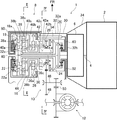
まず、図1乃至図3により、本発明の第1実施形態による自動変速機を適用したパワートレイン構造の全体構成を説明する。図1は、本発明の第1実施形態による自動変速機の中心軸線を通る水平断面を上方から見たスケルトン図であり、図2は、図1に示した本発明の第1実施形態による自動変速機のII−II矢視図であり、図3は、図1に示した本発明の第1実施形態による自動変速機の締結表である。
Hereinafter, an automatic transmission according to an embodiment of the present invention will be described with reference to the accompanying drawings.
First, an overall configuration of a powertrain structure to which the automatic transmission according to the first embodiment of the present invention is applied will be described with reference to FIGS. FIG. 1 is a skeleton diagram showing a horizontal cross section passing through the central axis of the automatic transmission according to the first embodiment of the present invention as viewed from above, and FIG. 2 is an automatic diagram according to the first embodiment of the present invention shown in FIG. FIG. 3 is an II-II arrow view of the transmission, and FIG. 3 is a fastening table of the automatic transmission according to the first embodiment of the present invention shown in FIG.
まず、図1において、符号1はパワートレイン構造を示している。このパワートレイン構造1は、エンジン2を車両の前部に横置き搭載した前輪駆動車(FF車)に適用されている。図1における矢印FRは、パワートレイン構造1を適用したFF車の進行方向を示す。
この車両の動力源であるエンジン2の出力軸4には、トルクコンバータ6を介して自動変速機8が接続されている。この自動変速機8の出力側にはカウンタ機構10が接続されており、自動変速機8からカウンタ機構10を介して出力される動力により、デファレンシャル機構12が駆動される。
First, in FIG. 1, the code |
An
自動変速機8は、エンジン2により生成された動力がトルクコンバータ6を介して入力される入力軸14を備えており、この入力軸14の周りに、変速機構16が配置されている。
また、自動変速機8は、エンジン2の出力軸4から自動変速機8の入力軸14に入力された動力を変速機構16に伝達する第1クラッチ18、第2クラッチ20及び第3クラッチ22を備えている。第2クラッチ20は、入力軸14に入力された動力を変速機構16、第1クラッチ18及び第3クラッチ22に伝達する。第1クラッチ18及び第3クラッチ22は、第2クラッチ20から入力された動力を変速機構16に伝達する。また、自動変速機8は、変速機構16に含まれる回転要素の作動を制限する第1ブレーキ24及び第2ブレーキ26を備えている。
さらに、変速機構16と第2クラッチ20との間に、変速機構16からの動力を出力する出力ギヤ28が配置されている。
The
The
Further, an
そして、これらの入力軸14、変速機構16、クラッチ18、20、22、ブレーキ24、26、及び出力ギヤ28が、変速機ケース30に格納されている。この変速機ケース30は、入力軸14、変速機構16、クラッチ18、20、22、ブレーキ24、26、及び出力ギヤ28の周りに形成されたケース部32と、このケース部32のエンジン2側の端面に取り付けられたハウジング部34とを有している。ケース部32は、このケース部32の外周を形成するケース部本体32aと、ケース部32のエンジン2側の端面においてケース部32とハウジング部34とを区画する隔壁32bと、ケース部32のエンジン2から遠い側の端面を形成するエンドカバー32cとを有する。ハウジング部34は、ケース部32の隔壁32bからエンジン2に向かって外径が拡大するように形成されている。このハウジング部34には、トルクコンバータ6が収容される。
The
変速機構16は、入力軸14の周りに配置された第1プラネタリギヤセット36、第2プラネタリギヤセット38、第3プラネタリギヤセット40、及び第4プラネタリギヤセット42を含んでいる。これらのプラネタリギヤセット36、38、40、42の内、第2プラネタリギヤセット38は第3プラネタリギヤセット40の外周部に重ねて配置されており、これらの第2プラネタリギヤセット38と第3プラネタリギヤセット40とによって複数段プラネタリギヤセット44が構成されている。この複数段プラネタリギヤセット44の径方向寸法は、第1プラネタリギヤセット36、第4プラネタリギヤセット42、及び出力ギヤ28のそれぞれの径方向寸法よりも大きい。
これらのプラネタリギヤセット36、38、40、42は、入力軸14が延びる方向に沿って、エンジン2に遠い側からエンジン2に向かって、複数段プラネタリギヤセット44、第1プラネタリギヤセット36、第4プラネタリギヤセット42の順に配置され、この第4プラネタリギヤセット42のエンジン2側に隣接して出力ギヤ28が配置されている。
各プラネタリギヤセット36、38、40、42は、それぞれ、外歯車のサンギヤ36a、38a、40a、42aと、このサンギヤ36a、38a、40a、42aに噛み合った複数のプラネタリピニオンと、これらのプラネタリピニオンを支持するキャリヤ36b、38b、40b、42bと、ピニオンに噛み合った内歯車のリングギヤ36c、38c、40c、42cとを備えている。
The
These planetary gear sets 36, 38, 40, 42 are arranged in a multi-stage planetary gear set 44, a first planetary gear set 36, a fourth planetary gear from the side far from the
Each planetary gear set 36, 38, 40, 42 includes external gear sun gears 36 a, 38 a, 40 a, 42 a, a plurality of planetary pinions meshed with the sun gears 36 a, 38 a, 40 a, 42 a, and these planetary pinions.
特に、図1及び図2に示すように、複数段プラネタリギヤセット44は、内周側の第3プラネタリギヤセット40のリングギヤ40cと、外周側の第2プラネタリギヤセット38のサンギヤ38aが連結された連結型プラネタリギヤセットとなっている。
In particular, as shown in FIGS. 1 and 2, the multi-stage planetary gear set 44 is a connection type in which a
そして、入力軸14が第3プラネタリギヤセット40のキャリヤ40bに連結されていると共に、第2プラネタリギヤセット38のキャリヤ38bと第4プラネタリギヤセット42のキャリヤ42bとが連結され、第1プラネタリギヤセット36のキャリヤ36bと第4プラネタリギヤセット42のリングギヤ42cとが連結され、第4プラネタリギヤセット42のキャリヤ42bと出力ギヤ28とが連結されている。
The
また、第2クラッチ20は、出力ギヤ28よりもエンジン2側に配置され、第1クラッチ18及び第3クラッチ22は、複数段プラネタリギヤセット44に隣接して、第1クラッチ18が第3クラッチ22の外周部に重なるように配置されている。第1クラッチ18及び第2クラッチ20のそれぞれの径方向寸法は、複数段プラネタリギヤセット44の径方向寸法よりも小さい。
The second clutch 20 is disposed on the
そして、第1プラネタリギヤセット36のサンギヤ36a、第1クラッチ18、及び第3クラッチ22は、それぞれ第2クラッチ20の出力軸20aに連結されており、これにより、第2クラッチ20を介して入力軸14に断接可能に連結されている。
また、第2プラネタリギヤセット38のリングギヤ38cは、第1クラッチ18の出力軸18aに連結されており、これにより、第1クラッチ18及び第2クラッチ20を介して入力軸14に断接可能に連結されている。
また、第2プラネタリギヤセット38のサンギヤ38a(即ち、第3プラネタリギヤセット40のリングギヤ40c)は、第3クラッチ22の出力軸22aに連結されており、これにより、第3クラッチ22及び第2クラッチ20を介して入力軸14に断接可能に連結されている。
The
Further, the
The
また、第1ブレーキ24は、第2クラッチ20と出力ギヤ28との間においてケース部本体32aの内周に固定されており、第3プラネタリギヤセット40のサンギヤ40a及び第4プラネタリギヤセット42のサンギヤ42aと連結されて、これらのサンギヤ40a、42aの作動を制限する。この第1ブレーキ24の径方向寸法は、複数段プラネタリギヤセット44の径方向寸法よりも小さい。
また、第2ブレーキ26は、第1プラネタリギヤセット36のリングギヤ36cの外周部においてケース部本体32aの内周に固定されており、第1プラネタリギヤセット36のリングギヤ36cと連結されて、このリングギヤ36cの作動を制限する。この第2ブレーキ26の径方向寸法は、第1ブレーキ24、第4プラネタリギヤセット42及び出力ギヤ28のそれぞれの径方向寸法よりも大きい。
The
The
上述した第1クラッチ18、第2クラッチ20、第3クラッチ22、第1ブレーキ24、及び第2ブレーキ26の締結状態の組み合わせにより、所望の前進変速段又は後退変速段が得られる。本実施形態の自動変速機8は、図3の締結表に示すように、前進8速及び後退速を出力可能となっている。なお、図3の締結表における丸印は、クラッチ18、20、22又はブレーキ24、26が締結状態にあることを示し、無印は、クラッチ18、20、22又はブレーキ24、26が解放状態にあることを示している。
A desired forward shift speed or reverse shift speed is obtained by a combination of the engagement states of the first clutch 18, the second clutch 20, the third clutch 22, the
例えば、自動変速機8の1速においては、第1クラッチ18及び第3クラッチ22が解放され、且つ、第2クラッチ20、第1ブレーキ24、及び第2ブレーキ26が締結される。これにより、入力軸14の回転は、第3プラネタリギヤセット40のキャリヤ40bに伝達されると共に、第2クラッチ20を介して第1プラネタリギヤセット36のサンギヤ36aに伝達される。このサンギヤ36aの回転は、第1プラネタリギヤセット36のキャリヤ36bから第4プラネタリギヤセット42のリングギヤ42cに減速出力される。そして、このリングギヤ42cの回転は、第4プラネタリギヤセット42のキャリヤ42bから出力ギヤ28に減速出力される。
For example, at the first speed of the
次に、図1に示すように、カウンタ機構10は、第2クラッチ20及び出力ギヤ28の外周側(図1では車両後方側)に配置されている。カウンタ機構10は、自動変速機8の入力軸14と平行に延びるように配置されたカウンタ軸46と、このカウンタ軸46上に設けられると共に自動変速機8の出力ギヤ28により駆動されるカウンタ入力部48と、カウンタ軸46上に設けられると共にデファレンシャル機構12を駆動するカウンタ出力部50とを有する。即ち、自動変速機8の出力ギヤ28から出力された動力は、カウンタ入力部48からカウンタ軸46を介してカウンタ出力部50に伝達され、このカウンタ出力部50に連結されたデファレンシャル機構12に出力される。
Next, as shown in FIG. 1, the
次に、自動変速機8のクラッチ18、20、22を作動させるための構成について、図1、図2及び図4を参照して説明する。図4は、図1に示した本発明の第1実施形態による自動変速機8のIV−IV矢視図である。
Next, a configuration for operating the
ここで、第1クラッチ18、第2クラッチ20、及び第3クラッチ22は、それぞれ、クラッチ18、20、22の出力軸18a、20a、22aに固定された摩擦板と、この摩擦板を挟み込むようにクラッチ18、20、22の入力軸に固定された摩擦相手板とを有し、さらに、これらの摩擦板と摩擦相手板とを互いに圧接させる方向(入力軸14の軸線方向)に作動する締結ピストンを有している。また、第1クラッチ18、第2クラッチ20、及び第3クラッチ22は、それぞれ、締結ピストンの締結を制御するための作動油が供給される締結油圧室と、この締結油圧室内の作動油が締結油圧室と共に入力軸14の周りを回転することにより発生する遠心圧を打ち消す遠心キャンセル室とを備えている。この遠心キャンセル室は、入力軸14が延びる方向に沿って、締結ピストンに対して締結油圧室の反対側に設けられている。
Here, the first clutch 18, the second clutch 20, and the third clutch 22 sandwich the friction plates fixed to the
そして、第1クラッチ18、第2クラッチ20、及び第3クラッチ22のそれぞれの締結油圧室に対する作動油の供給及び排出を制御するバルブボディが、自動変速機8の近傍に配置されている。さらに、バルブボディと、第1クラッチ18、第2クラッチ20、及び第3クラッチ22のそれぞれの締結油圧室とを連通させる油路52が、ケース部本体32aに形成されている。
A valve body that controls supply and discharge of hydraulic fluid to and from the engagement hydraulic chambers of the first clutch 18, the second clutch 20, and the third clutch 22 is disposed in the vicinity of the
また、図1及び図4に示すように、第1クラッチ18、第2クラッチ20及び第3クラッチ22のそれぞれの遠心キャンセル室に供給され又は遠心キャンセル室から排出される作動油を貯留するオイル貯留部54が、外周にブレーキが配置されていない第4プラネタリギヤセット42の外周部、出力ギヤ28の外周部、第1ブレーキ24の外周部、及び第2クラッチ20の外周部にわたって、変速機ケース30のケース部32に設けられている。即ち、オイル貯留部54は、複数段プラネタリギヤセット44及び外周部に第2ブレーキ26が配置されている第1プラネタリギヤセット36から、入力軸14が延びる方向に沿ってエンジン2側にオフセットした位置に配置されている。
オイル貯留部54は、上方に向かって開口したほぼ直方体形状の箱体であり、その底面が入力軸14とほぼ同じ高さ位置となるように、ケース部本体32aの外周の車両前方側において、ケース部本体32aと一体に設けられている。また、オイル貯留部54には、その上面の開口を覆うカバー56が設けられている。さらに、オイル貯留部54の上部には、このオイル貯留部54と変速機ケース30の内部とを連通させるように開口58が形成されており、余剰の作動油がオイル貯留部54からこの開口58を介して変速機ケース30内に還流可能となっている。
さらに、このオイル貯留部54の下端部と、第1クラッチ18、第2クラッチ20及び第3クラッチ22のそれぞれの遠心キャンセル室とを連通させる油路60が、ケース部32のケース部本体32a、隔壁32b、エンドカバー32cに形成されている。オイル貯留部54は、油路60の遠心キャンセル室側の出口よりも上方に設けられているので、オイル貯留部54内の作動油は、重力によって遠心キャンセル室に供給される。
As shown in FIGS. 1 and 4, an oil reservoir that stores hydraulic oil supplied to or discharged from the centrifugal cancel chambers of the first clutch 18, the second clutch 20, and the third clutch 22. The
The
Furthermore, an
次に、上述した本発明の第1実施形態による自動変速機8の効果を説明する。
Next, the effect of the
まず、オイル貯留部54は、入力軸14が延びる方向に沿って複数段プラネタリギヤセット44からオフセットした位置に配置されるので、オイル貯留部54の位置を、このオイル貯留部54が複数段プラネタリギヤセット44の外周部に配置される場合よりも内周側にすることができ、これにより、自動変速機8の軸方向寸法の増大を抑制するためにオイル貯留部54を自動変速機8の外周部に配置しつつ、自動変速機8の径方向寸法の大型化も抑制することができる。
First, since the
また、オイル貯留部54は、複数段プラネタリギヤセット44よりも径方向寸法の小さい第3プラネタリギヤセット40の外周部に配置されるので、自動変速機8の軸方向寸法の増大を抑制するためにオイル貯留部54を自動変速機8の外周部に配置しつつ、自動変速機8の径方向寸法の大型化も抑制することができる。
In addition, since the
また、オイル貯留部54は、ブレーキが配置されていない第3プラネタリギヤセット40の外周部に配置されているので、オイル貯留部54の位置を、第2ブレーキ26が配置された第1プラネタリギヤセット36の外周部にオイル貯留部54が配置される場合よりも内周側にすることができ、これにより、自動変速機8の軸方向寸法の増大を抑制するためにオイル貯留部54を自動変速機8の外周部に配置しつつ、自動変速機8の径方向寸法の大型化も抑制することができる。
Moreover, since the
また、オイル貯留部54は、複数段プラネタリギヤセット44よりも径方向寸法の小さい第3プラネタリギヤセット40の外周部且つ出力ギヤ28の外周部に配置されるので、自動変速機8の軸方向寸法の増大を抑制するためにオイル貯留部54を自動変速機8の外周部に配置しつつ、自動変速機8の径方向寸法の大型化も抑制することができ、さらに、オイル貯留部54の容積を増大させることができる。
Further, since the
次に、図5により、本発明の第2実施形態を説明する。この第2実施形態は、上述した第1実施形態におけるオイル貯留部54の配置が異なるものであり、他の構成は同一であるので、ここでは、異なる点についてのみ説明する。図5は、本発明の第2実施形態による自動変速機8の中心軸線を通る水平断面を上方から見たスケルトン図である。
Next, a second embodiment of the present invention will be described with reference to FIG. In the second embodiment, the arrangement of the
この第2実施形態によれば、図5に示すように、第2ブレーキ26の径方向寸法は、複数段プラネタリギヤセット44の径方向寸法よりも小さい。そして、オイル貯留部54は、第2ブレーキ26の外周部(即ち第1プラネタリギヤセット36の外周部)、第4プラネタリギヤセット42の外周部、出力ギヤ28の外周部、第1ブレーキ24の外周部、及び第2クラッチ20の外周部にわたって、変速機ケース30のケース部32に設けられている。即ち、オイル貯留部54は、複数段プラネタリギヤセット44の外周部から、入力軸14が延びる方向に沿ってエンジン2側にオフセットした位置に配置されている。
According to the second embodiment, as shown in FIG. 5, the radial dimension of the
このように第2実施形態によれば、オイル貯留部54は、入力軸14が延びる方向に沿って複数段プラネタリギヤセット44からオフセットした位置に配置されるので、オイル貯留部54の位置を、このオイル貯留部54が複数段プラネタリギヤセット44の外周部に配置される場合よりも内周側にすることができ、これにより、自動変速機8の軸方向寸法の増大を抑制するためにオイル貯留部54を自動変速機8の外周部に配置しつつ、自動変速機8の径方向寸法の大型化も抑制することができる。従って、上述した第1実施形態と同様の効果が得られる。
Thus, according to the second embodiment, the
次に、図6により、本発明の第3実施形態を説明する。この第3実施形態は、上述した第1実施形態におけるオイル貯留部54の配置が異なるものであり、他の構成は同一であるので、ここでは、異なる点についてのみ説明する。図6は、本発明の第3実施形態による自動変速機8の中心軸線を通る水平断面を上方から見たスケルトン図である。
Next, a third embodiment of the present invention will be described with reference to FIG. In the third embodiment, the arrangement of the
この第3実施形態によれば、図6に示すように、第1クラッチ18及び第3クラッチ22のそれぞれの遠心キャンセル室に供給され又は遠心キャンセル室から排出される作動油を貯留するオイル貯留部54aが、第1クラッチ18の外周部において、変速機ケース30のケース部32に設けられている。即ち、オイル貯留部54aは、複数段プラネタリギヤセット44から、入力軸14が延びる方向に沿ってエンジン2とは反対側にオフセットした位置に配置されている。
また、第2クラッチ20の遠心キャンセル室に供給され又は遠心キャンセル室から排出される作動油を貯留するオイル貯留部54bが、第2クラッチ20の外周部において、変速機ケース30のケース部32に設けられている。即ち、オイル貯留部54bは、複数段プラネタリギヤセット44から、入力軸14が延びる方向に沿ってエンジン2側にオフセットした位置に配置されている。
According to the third embodiment, as shown in FIG. 6, an oil reservoir that stores hydraulic oil that is supplied to or discharged from the centrifugal cancel chambers of the first clutch 18 and the third clutch 22. 54 a is provided in the
In addition, an
このように第3実施形態によれば、オイル貯留部54a、54bは、入力軸14が延びる方向に沿って複数段プラネタリギヤセット44からオフセットした位置に配置されるので、オイル貯留部54a、54bの位置を、このオイル貯留部54a、54bが複数段プラネタリギヤセット44の外周部に配置される場合よりも内周側にすることができ、これにより、自動変速機8の軸方向寸法の増大を抑制するためにオイル貯留部54a、54bを自動変速機8の外周部に配置しつつ、自動変速機8の径方向寸法の大型化も抑制することができる。従って、上述した第1実施形態と同様の効果が得られる。
As described above, according to the third embodiment, the
次に、図7及び図8により、本発明の第4実施形態を説明する。この第4実施形態は、上述した第1実施形態におけるクラッチ18、20、22、ブレーキ24、26、出力ギヤ28、プラネタリギヤセット36、38、40、42、及びオイル貯留部54の配置が異なるものであり、他の構成は同一であるので、ここでは、異なる点についてのみ説明する。図7は、本発明の第4実施形態による自動変速機8の中心軸線を通る水平断面を上方から見たスケルトン図であり、図8は、図7に示した本発明の第4実施形態による自動変速機8の締結表である。
Next, a fourth embodiment of the present invention will be described with reference to FIGS. In the fourth embodiment, the arrangements of the
この第4実施形態によれば、図7に示すように、プラネタリギヤセット36、38、40、42は、入力軸14が延びる方向に沿って、エンジン2に遠い側からエンジン2に向かって、第1プラネタリギヤセット36、複数段プラネタリギヤセット44、第4プラネタリギヤセット42の順に配置され、複数段プラネタリギヤセット44と第4プラネタリギヤセット42との間に、この第4プラネタリギヤセット42に隣接して出力ギヤ28が配置されている。
According to the fourth embodiment, as shown in FIG. 7, the planetary gear sets 36, 38, 40, 42 are arranged in the first direction from the side far from the
そして、入力軸14が第3プラネタリギヤセット40のキャリヤ40b及び第4プラネタリギヤセット42のサンギヤ42aに連結されていると共に、第1プラネタリギヤセット36のサンギヤ36aと第2プラネタリギヤセット38のリングギヤ38cとが連結され、第4プラネタリギヤセット42のリングギヤ42cと出力ギヤ28とが連結されている。
The
また、第1クラッチ18及び第2クラッチ20は、複数段プラネタリギヤセット44のエンジン2側に隣接して、第1クラッチ18が第2クラッチ20の外周部に重なるように配置され、第3クラッチ22は、第1プラネタリギヤセット36と複数段プラネタリギヤセット44の間に配置されている。
The first clutch 18 and the second clutch 20 are arranged adjacent to the
第1クラッチ18及び第2クラッチ20は、それぞれ第4プラネタリギヤセット42のキャリヤ42bと連結されている。また、第3クラッチ22は、第1プラネタリギヤセット36のキャリヤ36b及び第3プラネタリギヤセット40のサンギヤ40aと連結されている。
そして、第2プラネタリギヤセット38のキャリヤ38bは、第1クラッチ18の出力軸18a及び第3クラッチ22の出力軸22aに連結されており、これにより、第1クラッチ18を介して第4プラネタリギヤセット42のキャリヤ42bに断接可能に連結され、第3クラッチ22を介して第1プラネタリギヤセット36のキャリヤ36bに断接可能に連結されている。
また、第3プラネタリギヤセット40のリングギヤ40c(即ち第2プラネタリギヤセット38のサンギヤ38a)は、第2クラッチ20の出力軸20aに連結されており、これにより、第2クラッチ20を介して第4プラネタリギヤセット42のキャリヤ42bに断接可能に連結されている。
The first clutch 18 and the second clutch 20 are connected to the
The
Further, the
また、第1ブレーキ24は、第1プラネタリギヤセット36のリングギヤ36cの外周部においてケース部本体32aの内周に固定されており、第1プラネタリギヤセット36のリングギヤ36cと連結されて、このリングギヤ36cの作動を制限する。この第1ブレーキ24の径方向寸法は、複数段プラネタリギヤセット44の径方向寸法よりも小さい。
また、第2ブレーキ26は、第1プラネタリギヤセット36よりもエンジン2から遠い側においてケース部本体32aの内周に固定されており、第1プラネタリギヤセット36のサンギヤ36aと連結されて、このサンギヤ36aの作動を制限する。
The
The
上述した第1クラッチ18、第2クラッチ20、第3クラッチ22、第1ブレーキ24、及び第2ブレーキ26の締結状態の組み合わせにより、上述した第1実施形態と同様に、所望の前進変速段又は後退変速段が得られる。本実施形態の自動変速機8は、図8の締結表に示すように、前進8速及び後退速を出力可能となっている。なお、図8の締結表における丸印は、クラッチ18、20、22又はブレーキ24、26が締結状態にあることを示し、無印は、クラッチ18、20、22又はブレーキ24、26が解放状態にあることを示している。
Similar to the first embodiment described above, the desired forward shift speed or the combination of the engagement states of the first clutch 18, the second clutch 20, the third clutch 22, the
この第4実施形態では、図7に示すように、第1クラッチ18及び第2クラッチ20のそれぞれの遠心キャンセル室に供給され又は遠心キャンセル室から排出される作動油を貯留するオイル貯留部54aが、出力ギヤ28の外周部及び第4プラネタリギヤセット42の外周部において、変速機ケース30のケース部32に設けられている。即ち、オイル貯留部54aは、複数段プラネタリギヤセット44から、入力軸14が延びる方向に沿ってエンジン2側にオフセットした位置に配置されている。
また、第3クラッチ22の遠心キャンセル室に供給され又は遠心キャンセル室から排出される作動油を貯留するオイル貯留部54bが、第1プラネタリギヤセット36の外周部において、この第1プラネタリギヤセット36の外周部に配置された第1ブレーキ24に隣接して、変速機ケース30のケース部32に設けられている。即ち、第1ブレーキ24及びオイル貯留部54bは、第1プラネタリギヤセット36の外周部において、入力軸14が延びる方向に沿って互いにオフセットして配置されている。また、オイル貯留部54bは、複数段プラネタリギヤセット44から、入力軸14が延びる方向に沿ってエンジン2から遠い側にオフセットした位置に配置されている。
In the fourth embodiment, as shown in FIG. 7, an
In addition, an
このように第4実施形態によれば、第1ブレーキ24及びオイル貯留部54bは、第1プラネタリギヤセット36の外周部において、入力軸14が延びる方向に沿って互いにオフセットして配置されているので、複数段プラネタリギヤセット44よりも径方向寸法の小さい第1プラネタリギヤセット36の外周部に第1ブレーキ24が設けられている場合でも、オイル貯留部54bをその第1プラネタリギヤセット36の外周部に配置することができ、これにより、自動変速機8の軸方向寸法の増大を抑制するためにオイル貯留部54bを自動変速機8の外周部に配置しつつ、自動変速機8の径方向寸法の大型化も抑制することができる。
As described above, according to the fourth embodiment, the
次に、図9により、本発明の第5実施形態を説明する。この第5実施形態は、上述した第4実施形態におけるオイル貯留部54bの配置が異なるものであり、他の構成は同一であるので、ここでは、異なる点についてのみ説明する。図9は、本発明の第5実施形態による自動変速機8の中心軸線を通る水平断面を上方から見たスケルトン図である。
Next, a fifth embodiment of the present invention will be described with reference to FIG. In the fifth embodiment, the arrangement of the
この第5実施形態によれば、図9に示すように、オイル貯留部54bが、第1プラネタリギヤセット36の外周部に配置された第1ブレーキ24の外周部において、変速機ケース30のケース部32に設けられている。即ち、オイル貯留部54bは、複数段プラネタリギヤセット44から、入力軸14が延びる方向に沿ってエンジン2から遠い側にオフセットした位置に配置されている。
According to the fifth embodiment, as shown in FIG. 9, the
このように第5実施形態によれば、オイル貯留部54a、54bは、入力軸14が延びる方向に沿って複数段プラネタリギヤセット44からオフセットした位置に配置されるので、オイル貯留部54a、54bの位置を、このオイル貯留部54a、54bが複数段プラネタリギヤセット44の外周部に配置される場合よりも内周側にすることができ、これにより、自動変速機8の軸方向寸法の増大を抑制するためにオイル貯留部54a、54bを自動変速機8の外周部に配置しつつ、自動変速機8の径方向寸法の大型化も抑制することができる。従って、上述した第1実施形態と同様の効果が得られる。
As described above, according to the fifth embodiment, the
1 パワートレイン構造
2 エンジン
4 出力軸
8 自動変速機
14 入力軸
16 変速機構
18 第1クラッチ
20 第2クラッチ
22 第3クラッチ
24 第1ブレーキ
26 第2ブレーキ
28 出力ギヤ
36 第1プラネタリギヤセット
38 第2プラネタリギヤセット
40 第3プラネタリギヤセット
42 第4プラネタリギヤセット
36a、38a、40a、42a サンギヤ
36b、38b、40b、42b キャリヤ
36c、38c、40c、42c リングギヤ
44 複数段プラネタリギヤセット
52、60 油路
54、54a、54b オイル貯留部
DESCRIPTION OF
Claims (5)
上記動力源で生成された動力が入力される入力軸と、
上記入力軸の周りに、少なくとも2つのプラネタリギヤセットを内外周に重ねて配置して構成された1つ又は複数の複数段プラネタリギヤセットと、
上記動力源から上記入力軸に入力された動力を上記プラネタリギヤセットに伝達する1つ又は複数のクラッチであって、作動油が供給される締結油圧室と、この作動油による油圧を受けて移動する締結ピストンと、上記入力軸が延びる方向に沿って、上記締結ピストンに対して上記締結油圧室の反対側に設けられる遠心キャンセル室と、を有するクラッチと、
このクラッチの遠心キャンセル室へ油路を介して供給され又は上記遠心キャンセル室から油路を介して排出される作動油を貯留するオイル貯留部と、を有し、
上記オイル貯留部は、上記入力軸が延びる方向に沿って上記複数段プラネタリギヤセットからオフセットした位置に配置されていることを特徴とする自動変速機。 An automatic transmission that shifts and outputs power generated by a power source,
An input shaft to which power generated by the power source is input;
One or a plurality of multi-stage planetary gear sets configured by arranging at least two planetary gear sets on the inner and outer circumferences around the input shaft;
One or a plurality of clutches that transmit power input from the power source to the input shaft to the planetary gear set, and are moved by receiving a hydraulic pressure by the hydraulic oil and a fastening hydraulic chamber to which the hydraulic oil is supplied. A clutch having a fastening piston and a centrifugal cancellation chamber provided on the opposite side of the fastening hydraulic chamber with respect to the fastening piston along a direction in which the input shaft extends;
An oil reservoir that stores hydraulic oil that is supplied to the centrifugal cancel chamber of the clutch via an oil passage or discharged from the centrifugal cancel chamber via the oil passage;
The automatic transmission, wherein the oil reservoir is disposed at a position offset from the multi-stage planetary gear set along a direction in which the input shaft extends.
上記オイル貯留部は、上記1つ又は複数のプラネタリギヤセットの外周部に配置されている請求項1に記載の自動変速機。 And further comprising one or more planetary gear sets arranged around the input shaft,
The automatic transmission according to claim 1, wherein the oil storage portion is disposed on an outer peripheral portion of the one or more planetary gear sets.
上記オイル貯留部は、上記ブレーキが配置されていない上記1つ又は複数のプラネタリギヤセットの外周部に配置されている請求項2に記載の自動変速機。 And a brake that is disposed on an outer periphery of the planetary gear set and restricts the operation of any of the sun gear, the carrier, or the ring gear of the multi-stage planetary gear set and / or the one or more planetary gear sets,
The automatic transmission according to claim 2, wherein the oil storage portion is disposed on an outer peripheral portion of the one or more planetary gear sets where the brake is not disposed.
上記出力部は、上記1つ又は複数のプラネタリギヤセットに隣接して配置され、
上記オイル貯留部は、上記1つ又は複数のプラネタリギヤセットの外周部且つ上記出力部の外周部に配置されている請求項3に記載の自動変速機。 Furthermore, it has an output unit that outputs power from the multi-stage planetary gear set and / or the one or more planetary gear sets,
The output unit is disposed adjacent to the one or more planetary gear sets,
4. The automatic transmission according to claim 3, wherein the oil storage part is disposed on an outer peripheral part of the one or more planetary gear sets and on an outer peripheral part of the output part.
上記1つ又は複数のプラネタリギヤセット及び/又は上記複数段プラネタリギヤセットのサンギヤ、キャリヤ、又は、リングギヤのいずれかの作動を制限するブレーキと、を有し、
上記ブレーキ及び上記オイル貯留部は、上記1つ又は複数のプラネタリギヤセットの外周部において、上記入力軸が延びる方向に沿って互いにオフセットして配置されている請求項1に記載の自動変速機。 And one or more planetary gear sets disposed around the input shaft;
The one or more planetary gear sets and / or a brake that restricts the operation of any of the sun gear, carrier, or ring gear of the multi-stage planetary gear set,
2. The automatic transmission according to claim 1, wherein the brake and the oil storage portion are arranged offset from each other along a direction in which the input shaft extends in an outer peripheral portion of the one or more planetary gear sets.
Priority Applications (1)
| Application Number | Priority Date | Filing Date | Title |
|---|---|---|---|
| JP2014014186A JP6066100B2 (en) | 2014-01-29 | 2014-01-29 | Automatic transmission |
Applications Claiming Priority (1)
| Application Number | Priority Date | Filing Date | Title |
|---|---|---|---|
| JP2014014186A JP6066100B2 (en) | 2014-01-29 | 2014-01-29 | Automatic transmission |
Publications (2)
| Publication Number | Publication Date |
|---|---|
| JP2015140865A JP2015140865A (en) | 2015-08-03 |
| JP6066100B2 true JP6066100B2 (en) | 2017-01-25 |
Family
ID=53771346
Family Applications (1)
| Application Number | Title | Priority Date | Filing Date |
|---|---|---|---|
| JP2014014186A Active JP6066100B2 (en) | 2014-01-29 | 2014-01-29 | Automatic transmission |
Country Status (1)
| Country | Link |
|---|---|
| JP (1) | JP6066100B2 (en) |
Families Citing this family (1)
| Publication number | Priority date | Publication date | Assignee | Title |
|---|---|---|---|---|
| CN106438879B (en) * | 2016-07-13 | 2017-07-21 | 盛瑞传动股份有限公司 | Multiple-speed gear-box |
Family Cites Families (5)
| Publication number | Priority date | Publication date | Assignee | Title |
|---|---|---|---|---|
| JPH11325117A (en) * | 1998-05-11 | 1999-11-26 | Mazda Motor Corp | Hydraulic feed device to centrifugal balance chamber provided on friction clutch device of automatic transmission |
| DE602004012997T2 (en) * | 2004-08-26 | 2009-05-28 | Hoerbiger Antriebstechnik Gmbh | Hydraulic double clutch |
| JP4776352B2 (en) * | 2005-11-17 | 2011-09-21 | アイシン・エィ・ダブリュ株式会社 | Lubricating device for automatic transmission |
| JP2008309238A (en) * | 2007-06-14 | 2008-12-25 | Mazda Motor Corp | Automatic transmission |
| JP2014005917A (en) * | 2012-06-27 | 2014-01-16 | Masahiro Okubo | Multistage transmission of nine gears for forward drive and one gear for backward drive |
-
2014
- 2014-01-29 JP JP2014014186A patent/JP6066100B2/en active Active
Also Published As
| Publication number | Publication date |
|---|---|
| JP2015140865A (en) | 2015-08-03 |
Similar Documents
| Publication | Publication Date | Title |
|---|---|---|
| US8303457B2 (en) | Automatic transmission | |
| US7582039B2 (en) | Automatic transmission for automotive vehicles | |
| KR20120135877A (en) | Automatic transmission | |
| US10041570B2 (en) | Power transmission device | |
| US20090114501A1 (en) | Frictional engagement device | |
| CN103328855B (en) | Automatic transmission | |
| US8771131B2 (en) | Transmission device | |
| US20150362063A1 (en) | Power transmission apparatus | |
| JP6066100B2 (en) | Automatic transmission | |
| US9810313B2 (en) | Power transmission apparatus | |
| JP4697075B2 (en) | Automatic transmission | |
| JP2009197851A (en) | Clutch device for transmission | |
| JP6066098B2 (en) | Automatic transmission | |
| JP2009103229A (en) | Automatic transmission | |
| JP6061099B2 (en) | Automatic transmission | |
| JP6167815B2 (en) | Automatic transmission | |
| JP6065231B2 (en) | Powertrain structure | |
| JP2008309238A (en) | Automatic transmission | |
| CN108626369B (en) | Flow path structure of power transmission device | |
| JP6066099B2 (en) | Centrifugal canceling structure of power transmission clutch for automatic transmission | |
| JP6044520B2 (en) | Automatic transmission | |
| JP4619381B2 (en) | Fluid path structure of automatic transmission | |
| JP2008303962A (en) | Automatic transmission | |
| JP6065232B2 (en) | Centrifugal canceling structure of power transmission clutch for automatic transmission | |
| US9593749B2 (en) | Automatic transmission |
Legal Events
| Date | Code | Title | Description |
|---|---|---|---|
| A621 | Written request for application examination |
Free format text: JAPANESE INTERMEDIATE CODE: A621 Effective date: 20160225 |
|
| A977 | Report on retrieval |
Free format text: JAPANESE INTERMEDIATE CODE: A971007 Effective date: 20161125 |
|
| TRDD | Decision of grant or rejection written | ||
| A01 | Written decision to grant a patent or to grant a registration (utility model) |
Free format text: JAPANESE INTERMEDIATE CODE: A01 Effective date: 20161130 |
|
| A61 | First payment of annual fees (during grant procedure) |
Free format text: JAPANESE INTERMEDIATE CODE: A61 Effective date: 20161213 |
|
| R150 | Certificate of patent or registration of utility model |
Ref document number: 6066100 Country of ref document: JP Free format text: JAPANESE INTERMEDIATE CODE: R150 |