JP6047439B2 - Peeling apparatus and peeling method - Google Patents
Peeling apparatus and peeling method Download PDFInfo
- Publication number
- JP6047439B2 JP6047439B2 JP2013063862A JP2013063862A JP6047439B2 JP 6047439 B2 JP6047439 B2 JP 6047439B2 JP 2013063862 A JP2013063862 A JP 2013063862A JP 2013063862 A JP2013063862 A JP 2013063862A JP 6047439 B2 JP6047439 B2 JP 6047439B2
- Authority
- JP
- Japan
- Prior art keywords
- plate
- peeling
- contact
- holding
- substrate
- Prior art date
- Legal status (The legal status is an assumption and is not a legal conclusion. Google has not performed a legal analysis and makes no representation as to the accuracy of the status listed.)
- Active
Links
- 238000000034 method Methods 0.000 title claims description 39
- 238000001179 sorption measurement Methods 0.000 claims description 28
- 239000010409 thin film Substances 0.000 claims description 15
- 238000000926 separation method Methods 0.000 claims description 9
- 238000011144 upstream manufacturing Methods 0.000 claims description 2
- 238000013459 approach Methods 0.000 claims 1
- 206010040844 Skin exfoliation Diseases 0.000 description 212
- 239000000758 substrate Substances 0.000 description 113
- 230000008569 process Effects 0.000 description 22
- 238000003825 pressing Methods 0.000 description 16
- 230000007246 mechanism Effects 0.000 description 13
- 238000005452 bending Methods 0.000 description 8
- 238000012546 transfer Methods 0.000 description 7
- 238000010586 diagram Methods 0.000 description 5
- 230000002093 peripheral effect Effects 0.000 description 5
- 210000000078 claw Anatomy 0.000 description 4
- 230000008901 benefit Effects 0.000 description 3
- 238000006243 chemical reaction Methods 0.000 description 3
- 239000000463 material Substances 0.000 description 3
- 238000000059 patterning Methods 0.000 description 3
- 238000012545 processing Methods 0.000 description 3
- 239000011247 coating layer Substances 0.000 description 2
- 230000003028 elevating effect Effects 0.000 description 2
- 239000011521 glass Substances 0.000 description 2
- 239000010410 layer Substances 0.000 description 2
- 230000002250 progressing effect Effects 0.000 description 2
- 230000000630 rising effect Effects 0.000 description 2
- 239000004065 semiconductor Substances 0.000 description 2
- XUIMIQQOPSSXEZ-UHFFFAOYSA-N Silicon Chemical compound [Si] XUIMIQQOPSSXEZ-UHFFFAOYSA-N 0.000 description 1
- 230000000052 comparative effect Effects 0.000 description 1
- 238000005336 cracking Methods 0.000 description 1
- 230000003247 decreasing effect Effects 0.000 description 1
- 230000003111 delayed effect Effects 0.000 description 1
- 230000000694 effects Effects 0.000 description 1
- 238000005516 engineering process Methods 0.000 description 1
- 239000004973 liquid crystal related substance Substances 0.000 description 1
- 238000012423 maintenance Methods 0.000 description 1
- 238000012986 modification Methods 0.000 description 1
- 230000004048 modification Effects 0.000 description 1
- 230000007261 regionalization Effects 0.000 description 1
- 239000011347 resin Substances 0.000 description 1
- 229920005989 resin Polymers 0.000 description 1
- 238000005096 rolling process Methods 0.000 description 1
- 229910052710 silicon Inorganic materials 0.000 description 1
- 239000010703 silicon Substances 0.000 description 1
Images


Classifications
-
- B—PERFORMING OPERATIONS; TRANSPORTING
- B65—CONVEYING; PACKING; STORING; HANDLING THIN OR FILAMENTARY MATERIAL
- B65H—HANDLING THIN OR FILAMENTARY MATERIAL, e.g. SHEETS, WEBS, CABLES
- B65H29/00—Delivering or advancing articles from machines; Advancing articles to or into piles
- B65H29/54—Article strippers, e.g. for stripping from advancing elements
- B65H29/56—Article strippers, e.g. for stripping from advancing elements for stripping from elements or machines
-
- B—PERFORMING OPERATIONS; TRANSPORTING
- B65—CONVEYING; PACKING; STORING; HANDLING THIN OR FILAMENTARY MATERIAL
- B65H—HANDLING THIN OR FILAMENTARY MATERIAL, e.g. SHEETS, WEBS, CABLES
- B65H2301/00—Handling processes for sheets or webs
- B65H2301/50—Auxiliary process performed during handling process
- B65H2301/51—Modifying a characteristic of handled material
- B65H2301/511—Processing surface of handled material upon transport or guiding thereof, e.g. cleaning
- B65H2301/5112—Processing surface of handled material upon transport or guiding thereof, e.g. cleaning removing material from outer surface
- B65H2301/51122—Processing surface of handled material upon transport or guiding thereof, e.g. cleaning removing material from outer surface peeling layer of material
-
- B—PERFORMING OPERATIONS; TRANSPORTING
- B65—CONVEYING; PACKING; STORING; HANDLING THIN OR FILAMENTARY MATERIAL
- B65H—HANDLING THIN OR FILAMENTARY MATERIAL, e.g. SHEETS, WEBS, CABLES
- B65H2701/00—Handled material; Storage means
- B65H2701/10—Handled articles or webs
- B65H2701/17—Nature of material
- B65H2701/172—Composite material
- B65H2701/1726—Composite material including detachable components
Landscapes
- Engineering & Computer Science (AREA)
- Mechanical Engineering (AREA)
- Container, Conveyance, Adherence, Positioning, Of Wafer (AREA)
- Folding Of Thin Sheet-Like Materials, Special Discharging Devices, And Others (AREA)
- Photosensitive Polymer And Photoresist Processing (AREA)
Description
この発明は、互いに密着した2枚の板状体を剥離して離間させる剥離装置および剥離方法に関するものである。 The present invention relates to a peeling apparatus and a peeling method for peeling and separating two plate-like bodies that are in close contact with each other.
ガラス基板や半導体基板などの板状体に所定のパターンや薄膜を形成する技術として、他の板状体に担持されたパターンや薄膜(以下、「パターン等」という)を基板に転写するものがある。この技術においては、2枚の板状体を密着させてパターン等を一方から他方に転写した後、パターン等を損壊させることなく2枚の板状体を剥離する必要がある。 As a technique for forming a predetermined pattern or thin film on a plate-like body such as a glass substrate or a semiconductor substrate, a technique for transferring a pattern or thin film (hereinafter referred to as “pattern etc.”) carried on another plate-like body onto the substrate. is there. In this technique, after two plates are brought into close contact with each other and a pattern or the like is transferred from one to the other, it is necessary to peel the two plates without damaging the pattern or the like.
この目的のために利用可能な技術として、例えば特許文献1には、液晶表示装置のカラーフィルタや電気回路配線などのパターンを記録媒体上に形成する技術において、画像形成層を有する受像シートを記録媒体に重ね合わせて描画を行った後、受像シートの支持層を記録媒体から剥離することで、記録媒体上に所定パターンを形成する。この技術においては、スクイーズローラとしての機能を兼ねる剥離ローラを受像シートに当接させながら、吸盤によって受像シートの一端部を吸着保持して引き上げて生じる受像シートと記録媒体との隙間に剥離爪を差し込んで記録媒体に対して相対移動させることにより、受像シートと記録媒体とを剥離している。 As a technique that can be used for this purpose, for example, Patent Document 1 records an image receiving sheet having an image forming layer in a technique for forming a pattern such as a color filter or an electric circuit wiring of a liquid crystal display device on a recording medium. After drawing on the medium, a predetermined pattern is formed on the recording medium by peeling the support layer of the image receiving sheet from the recording medium. In this technique, a peeling claw is provided in a gap between an image receiving sheet and a recording medium generated by sucking and holding one end of the image receiving sheet by a suction cup while a peeling roller that also functions as a squeeze roller is in contact with the image receiving sheet. The image receiving sheet and the recording medium are separated by being inserted and moved relative to the recording medium.
上記従来技術では、剥離ローラと剥離爪との位置関係を維持しつつ記録媒体に対し相対移動させることで一定の剥離力(両部材を離間させる力)が得られるが、剥離させたい2つの部材の一方部材に剥離爪を当接させているため、当該部材を損傷させてしまう。一方、部材の損傷を防止するために剥離爪を接触させないようにすると、良好に剥離を行うことができない場合がある。というのは、剥離の進行に伴って部材の撓みが増加することにより、両部材の引き離し動作に対する剥離の進行が次第に鈍るからである。このような剥離の進行速度の変動は、応力集中に起因するパターン等の損傷の原因となる。 In the above prior art, a constant peeling force (a force for separating both members) can be obtained by moving relative to the recording medium while maintaining the positional relationship between the peeling roller and the peeling claw. Since the peeling claw is brought into contact with one of the members, the member is damaged. On the other hand, if the peeling claw is not brought into contact in order to prevent damage to the member, it may not be possible to perform the peeling well. This is because the bending of the members increases with the progress of peeling, and the progress of peeling with respect to the separating operation of both members gradually slows down. Such fluctuations in the progressing speed of the peeling cause damage to patterns and the like due to stress concentration.
また、両部材を引き離すための移動量が大きくなりそのための作業スペースが大きくなったり、撓みによる部材の屈曲や割れ、保持力の不足に起因する部材の落下などの問題も生じてくる。これらの問題は、特に剥離すべき部材が大型化するにつれて顕著なものとなってきている。 In addition, the amount of movement for separating the two members increases, resulting in an increase in work space, bending of the member due to bending, cracking, and dropping of the member due to insufficient holding force. These problems have become particularly prominent as the member to be peeled becomes larger.
この発明は上記課題に鑑みなされたものであり、互いに密着した2枚の板状体を剥離して離間させる剥離装置および剥離方法において、良好に剥離を行うことができ、特に板状体の大型化にも対応することのできる技術を提供することを目的とする。 The present invention has been made in view of the above problems, and in a peeling apparatus and a peeling method that peels and separates two plate-like bodies that are in close contact with each other, it can be favorably peeled off. It aims at providing the technology which can respond also to conversion.
この発明の一の態様は、薄膜またはパターンを介して互いに密着した第1板状体と第2板状体とを剥離させる剥離装置において、上記目的を達成するため、第1板状体のうち薄膜またはパターンが形成された有効領域の平面サイズよりも大きい保持面を有し、該保持面に第1板状体の表面のうち第2板状体と密着した面とは反対側の面を当接させて第1板状体を保持する保持手段と、第2板状体の一端部を保持しながら保持手段から離間する方向に移動して、第2板状体の一端部を第1板状体から剥離させる第1剥離手段と、第2板状体の一端部から該一端部と反対側の他端部に向かう剥離進行方向に直交する方向に第2板状体に沿って延設されたローラ状に形成され、剥離進行方向における一端部の下流側に隣接する当接開始位置で、第1板状体と密着した面とは反対側の第2板状体の一方面に当接するとともに、第2板状体に当接しながら当接開始位置から他端部に向けて剥離進行方向に移動する当接手段と、剥離方向における当接開始位置の下流側で第2板状体の一方面に臨んで設けられ、当接手段が通過した後の第2板状体の一方面に部分的に当接して第2板状体を保持しながら保持手段から離間する方向に移動する第2剥離手段とを備えている。 One aspect of the present invention is to provide a peeling apparatus for peeling a first plate-like body and a second plate-like body which are in close contact with each other through a thin film or a pattern. The holding surface has a holding surface larger than the plane size of the effective area on which the thin film or the pattern is formed, and the surface on the opposite side of the surface of the first plate-like body that is in close contact with the second plate-like body on the holding surface The holding means for holding the first plate-like body by contact and the one end portion of the second plate-like body moving in a direction away from the holding means while holding the one end portion of the second plate-like body, First peeling means for peeling from the plate-like body, and extending along the second plate-like body in a direction perpendicular to the peeling progress direction from one end of the second plate-like body to the other end opposite to the one end. At the contact start position adjacent to the downstream side of the one end in the peeling progress direction, Abuts against one surface of the second plate-like body on the opposite side to the surface in close contact with the shaped body, and moves in the peeling progress direction from the contact start position toward the other end while contacting the second plate-like body The contact means is provided on one side of the second plate-like body downstream of the contact start position in the peeling direction and partially on one surface of the second plate-like body after the contact means has passed. And a second peeling means that moves in a direction away from the holding means while abutting and holding the second plate-like body.
このように構成された発明では、当接手段を第2板状体に当接させながら第1剥離手段が保持手段から離間する方向に移動することで、第1板状体からの第2板状体の剥離が進行する。このとき、当接手段が第1剥離手段から遠ざかるにつれて第1剥離手段の移動が剥離の進行に反映されにくくなるが、この発明では、剥離進行方向においてより下流側に設けた第2剥離手段により継続的に剥離を進行させることができる。また、第1剥離手段による一端部の保持のみでは第2板状体の撓みを抑えることができないが、一端部と他端部との間で第2剥離手段が第2板状体を保持することで、第2板状体の姿勢を制御することが可能である。このように、本発明によれば、互いに密着した第1板状体と第2板状体とを良好に剥離させることができ、これらの大型化にも柔軟に対応して、良好な剥離性能を発揮することができる。 In the invention configured in this manner, the second plate from the first plate-like body is moved by moving the first peeling means away from the holding means while the abutment means is in contact with the second plate-like body. The peeling of the state progresses. At this time, as the abutment means moves away from the first peeling means, the movement of the first peeling means is less likely to be reflected in the progress of peeling, but in the present invention, the second peeling means provided further downstream in the peeling progress direction. The peeling can be continuously progressed. Further, although the bending of the second plate-like body cannot be suppressed only by holding the one end portion by the first peeling means, the second peeling means holds the second plate-like body between the one end portion and the other end portion. Thus, the posture of the second plate-like body can be controlled. As described above, according to the present invention, the first plate-like body and the second plate-like body which are in close contact with each other can be peeled off satisfactorily, and good peeling performance can be flexibly accommodated to increase in size. Can be demonstrated.
なお、薄膜またはパターン(以下、「パターン等)という)を介して密着した第1板状体および第2板状体の面のうち、パターン等が有効に形成された有効領域またはその背面に当たる領域に保持のための部材を当接させた場合、当該箇所でパターン等に応力が集中してパターン等を損傷することがある。この発明では、当接手段が通過した後の、つまり第1板状体から剥離した後の第2板状体の一方面(パターン等が形成された面とは反対の面)を保持するので、このようなパターン等の損傷の問題は生じない。 Of the surfaces of the first plate and the second plate that are in close contact with each other through a thin film or a pattern (hereinafter referred to as “pattern”), an effective region where the pattern or the like is effectively formed, or a region corresponding to the back surface thereof. When the member for holding is brought into contact with the surface, stress may be concentrated on the pattern or the like at the location to damage the pattern, etc. In this invention, after the contact means passes, that is, the first plate Since one surface (the surface opposite to the surface on which the pattern or the like is formed) of the second plate-like body after being peeled from the shape body is held, such a problem of damage to the pattern or the like does not occur.
この発明では、例えば、複数の第2剥離手段が剥離進行方向に沿って配列され、該複数の第2剥離手段が互いに独立して保持手段に対して接近および離間移動するように構成されてもよい。このような構成では、第1板状体から第2板状体を離間させる作用を果たす第2剥離手段を当接手段の剥離進行方向に沿った移動に伴って順次切り換えることができ、安定した剥離力を第1板状体と第2板状体との間に与えながら剥離を進行させることができる。特に第1および第2板状体が大型である場合、そのサイズに応じて複数の第2剥離手段を設けることが効果的である。 In the present invention, for example, a plurality of second peeling means may be arranged along the peeling progress direction, and the plurality of second peeling means may be configured to move toward and away from the holding means independently of each other. Good. In such a configuration, the second peeling means that acts to separate the second plate-like body from the first plate-like body can be sequentially switched as the abutting means moves along the peeling progress direction, and is stable. The peeling can be advanced while applying the peeling force between the first plate-like body and the second plate-like body. In particular, when the first and second plate-like bodies are large, it is effective to provide a plurality of second peeling means according to the size.
また例えば、第1剥離手段は、第2板状体のうち薄膜またはパターンが形成された有効領域よりも外側で第2板状体を保持するように構成されてもよい。このような構成では、有効領域外で第2板状体を保持するので、第1剥離手段による保持がパターン等を損傷させることが防止される。 Further, for example, the first peeling means may be configured to hold the second plate-like body outside the effective region where the thin film or pattern is formed in the second plate-like body. In such a configuration, since the second plate-like body is held outside the effective area, the holding by the first peeling means is prevented from damaging the pattern or the like.
また例えば、第1剥離手段および第2剥離手段は、第2板状体の一方面に当接して第2板状体を吸着保持する構成であってもよい。このような構成では、パターン等に触れることなく第2板状体を保持することが可能であり、パターン等の損傷を防止することができる。また、例えば機械爪で第2板状体を把持したり、第1板状体との間に差し込む構成ではないため、第1および第2板状体の損傷も防止することができる。 Further, for example, the first peeling means and the second peeling means may be configured to abut against one surface of the second plate-like body and suck and hold the second plate-like body. In such a configuration, the second plate-like body can be held without touching the pattern or the like, and damage to the pattern or the like can be prevented. Further, for example, the second plate-like body is not gripped with a mechanical nail or inserted between the first plate-like body, and therefore damage to the first and second plate-like bodies can be prevented.
この場合、第2剥離手段のうち第2板状体に当接する当接部位は、例えば第2板状体に対して接近、離間する方向へ伸縮可能な弾性部材により形成されてもよい。本発明では、第1板状体から剥離した後に、第2剥離手段が第2板状体を保持する必要がある。このとき第2板状体はその背面がバックアップされないので、第2剥離手段との距離にばらつきがあり、また第2剥離手段の当接により反対側へ押し遣られる場合がある。第2剥離手段の当接部位を伸縮可能な弾性部材で構成することにより、そのような場合でも確実に第2板状体を保持することが可能となる。 In this case, the contact portion that contacts the second plate-like body of the second peeling means may be formed by an elastic member that can expand and contract in a direction approaching and separating from the second plate-like body, for example. In this invention, after peeling from a 1st plate-shaped body, it is necessary for a 2nd peeling means to hold | maintain a 2nd plate-shaped body. At this time, since the back surface of the second plate-like body is not backed up, the distance from the second peeling means varies, and the second plate-like body may be pushed to the opposite side by the contact of the second peeling means. By configuring the contact portion of the second peeling means with an elastic member that can be expanded and contracted, it is possible to reliably hold the second plate-like body even in such a case.
また例えば、第1剥離手段および第2剥離手段のそれぞれは、剥離進行方向に直交する方向に配列されて第2板状体に当接する複数の吸着パッドを有する構成であってもよい。このような構成では、第2板状体は剥離進行方向と直交する方向において複数箇所で吸着保持されることとなる。これにより、より強力に第2板状体を保持することが可能になるとともに、剥離進行方向と直交する方向における第2板状体の撓みを効果的に防止することができる。 For example, each of the first peeling means and the second peeling means may have a plurality of suction pads that are arranged in a direction orthogonal to the peeling progress direction and come into contact with the second plate-like body. In such a configuration, the second plate-like body is sucked and held at a plurality of locations in a direction orthogonal to the peeling progress direction. Thereby, it becomes possible to hold the second plate-like body more strongly, and it is possible to effectively prevent the second plate-like body from being bent in the direction orthogonal to the peeling progress direction.
また例えば、保持手段の保持面に、負圧が付与されて第1板状体を吸着する吸着孔または吸着溝が設けられる構成であってもよい。このような構成では、第1板状体の有効領域を平面状態に維持しながら確実に保持することができる。 Further, for example, the holding surface of the holding unit may be configured to be provided with suction holes or suction grooves that apply a negative pressure to suck the first plate-like body. In such a configuration, the effective area of the first plate-like body can be reliably held while being maintained in a planar state.
また、この発明の他の態様は、薄膜またはパターンを介して互いに密着した第1板状体と第2板状体とを剥離させる剥離方法において、上記目的を達成するため、第1板状体のうち薄膜またはパターンが形成された有効領域の平面サイズよりも大きい保持面に第1板状体の表面のうち第2板状体と密着した面とは反対側の面を当接させて第1板状体を保持する工程と、第2板状体の一端部から該一端部と反対側の他端部に向かう剥離進行方向における一端部の下流側に隣接する当接開始位置で、第1板状体と密着した面とは反対側の第2板状体の一方面に、剥離進行方向に直交する方向に延設されたローラ状の当接手段を当接させる工程と、第2板状体の一端部を第1板状体から離間する方向に移動させて、第2板状体の一端部を第1板状体から剥離させるとともに、当接手段を第2板状体に当接させながら当接開始位置から他端部に向けて剥離進行方向に移動させる工程と、当接手段を移動させながら、剥離方向における当接開始位置の下流側で、当接手段が通過し第1板状体から剥離した後の第2板状体の一方面を部分的に保持しながら第1板状体から離間する方向に移動させる工程とを備えている。 According to another aspect of the present invention, there is provided a peeling method for peeling a first plate-like body and a second plate-like body that are in close contact with each other through a thin film or a pattern. The surface of the first plate-like body opposite to the surface in close contact with the second plate-like body is brought into contact with the holding surface larger than the plane size of the effective area on which the thin film or pattern is formed. At the contact start position adjacent to the downstream side of the one end in the peeling progress direction from the one end of the second plate to the other end opposite to the one end. A step of abutting a roller-like abutting means extending in a direction orthogonal to the peeling progress direction on one surface of the second plate-like body on the opposite side to the surface in close contact with the one plate-like body; One end of the plate-like body is moved in a direction away from the first plate-like body, and one end of the second plate-like body is moved to the first plate-like body. And a step of moving the contact means from the contact start position toward the other end portion in the peeling progress direction while abutting the abutting means on the second plate-shaped body, and moving the abutting means in the peeling direction. In a direction away from the first plate-like body while partially holding one surface of the second plate-like body after the contact means passes and peels from the first plate-like body on the downstream side of the contact start position. And a step of moving.
このように構成された発明では、上記した剥離装置と同様に、第1板状体からの剥離に関わる第2板状体の保持位置を当接手段の移動に伴って下流側に切り換えることで、良好に剥離を進行させることができ、また第1および第2板状体の大型化にも対応することが可能である。 In the invention configured as described above, similarly to the above-described peeling device, the holding position of the second plate-like body related to the peeling from the first plate-like body is switched to the downstream side with the movement of the contact means. The peeling can proceed well, and it is possible to cope with the increase in size of the first and second plate-like bodies.
この発明では、例えば、第1板状体と第2板状体とが密着する未剥離領域と、第1板状体と第2板状体とが剥離した剥離領域との境界線である剥離境界線が当接開始位置に到達したときに当接手段の移動を開始し、一定速度で当接手段を移動させる構成としてもよい。このような構成では、剥離境界線を一定速度で剥離進行方向に移動させる、つまり剥離の進行速度を一定にすることができる。このため、応力集中に起因するパターン等の損傷を効果的に防止することが可能である。 In the present invention, for example, peeling is a boundary line between an unpeeled area where the first plate-like body and the second plate-like body are in close contact with a peeled area where the first plate-like body and the second plate-like body are peeled off. A configuration may be adopted in which movement of the contact means is started when the boundary line reaches the contact start position, and the contact means is moved at a constant speed. In such a configuration, the peeling boundary line can be moved in the peeling progress direction at a constant speed, that is, the peeling progress speed can be made constant. For this reason, it is possible to effectively prevent damage to patterns and the like due to stress concentration.
また例えば、第2板状体の一方面を保持する保持箇所を、当接手段の剥離進行方向への移動に伴って剥離進行方向に順次追加する構成であってもよい。このような構成では、複数の第2剥離手段を剥離進行方向に配列した上記剥離装置の発明と同様に、第1板状体からの剥離に関わる第2板状体の保持位置を当接手段の移動に伴って順次下流側に切り換えることで、第1および第2板状体が大型であっても安定した剥離力で剥離を進行させることができる。 Further, for example, a configuration may be adopted in which the holding portion that holds one surface of the second plate-like body is sequentially added in the peeling progress direction as the contact means moves in the peeling progress direction. In such a configuration, the holding position of the second plate-like body related to the peeling from the first plate-like body is set as the abutting means, similarly to the invention of the peeling device in which a plurality of second peeling means are arranged in the peeling progress direction. By sequentially switching to the downstream side along with the movement, even if the first and second plate-like bodies are large, peeling can proceed with a stable peeling force.
また例えば、当接手段との当接箇所における第2板状体の曲率を所定範囲に維持しながら、当接手段の剥離進行方向への移動と第2板状体の前記第1板状体から離間する方向への移動とを行う構成であってもよい。このような構成では、当接手段への当接と第1板状体からの離間移動によって当接手段との当接箇所で撓ませられる第2板状体の撓み量が安定した状態で剥離が進行する。そのため、剥離の初期段階から完了までの間、第1板状体と第2板状体との間に安定した剥離力を与えながら剥離を進行させることができる。 Further, for example, while maintaining the curvature of the second plate-like body at the contact portion with the contact means within a predetermined range, the movement of the contact means in the peeling progress direction and the first plate-like body of the second plate-like body. The structure which performs the movement to the direction which leaves | separates from may be sufficient. In such a configuration, the second plate-shaped body that is bent at the contact position with the contact means by the contact with the contact means and the separation movement from the first plate-shaped body is peeled in a stable state. Progresses. Therefore, during the period from the initial stage to the completion of the peeling, the peeling can be advanced while giving a stable peeling force between the first plate-like body and the second plate-like body.
また例えば、剥離進行方向において当接手段との当接箇所よりも上流側では第2板状体の姿勢を略平面に保持する構成であってもよい。このような構成では、剥離後の第2板状体に無用な曲げ応力が加わるのを防止することができる。 Further, for example, a configuration in which the posture of the second plate-like body is held substantially flat on the upstream side of the contact portion with the contact means in the peeling progress direction. With such a configuration, it is possible to prevent unnecessary bending stress from being applied to the second plate-like body after peeling.
また例えば、第2板状体の全体が第1板状体から剥離した後、第2板状体を第1板状体に対して平行に保持する構成であってもよい。このような構成では、第1板状体から剥離した第2板状体を第1板状体と平行に保持することで、第1および第2板状体の搬出を容易に行うことができる。 For example, after the 2nd plate-shaped body whole peels from the 1st plate-shaped body, the structure hold | maintained in parallel with respect to a 1st plate-shaped body may be sufficient. In such a configuration, the first and second plate bodies can be easily carried out by holding the second plate body separated from the first plate body in parallel with the first plate body. .
この発明によれば、第1板状体からの剥離に関わる第2板状体の保持位置を当接手段の移動に伴って下流側に切り換えることで、良好に剥離を進行させることができ、剥離対象物が大型であっても良好に剥離することができる。 According to this invention, by switching the holding position of the second plate-like body related to the peeling from the first plate-like body to the downstream side with the movement of the contact means, the peeling can be favorably progressed, Even if the object to be peeled is large, it can be peeled off satisfactorily.
図1はこの発明にかかる剥離装置の一実施形態を示す斜視図である。各図における方向を統一的に示すために、図1右下に示すようにXYZ直交座標軸を設定する。ここでXY平面が水平面、Z軸が鉛直軸を表す。より詳しくは、(+Z)方向が鉛直上向き方向を表している。 FIG. 1 is a perspective view showing an embodiment of a peeling apparatus according to the present invention. In order to uniformly indicate the direction in each figure, XYZ orthogonal coordinate axes are set as shown in the lower right of FIG. Here, the XY plane represents a horizontal plane and the Z axis represents a vertical axis. More specifically, the (+ Z) direction represents a vertically upward direction.
この剥離装置1は、主面同士が互いに密着した状態で搬入される2枚の板状体を剥離させるための装置である。例えばガラス基板や半導体基板等の基板の表面に所定のパターンを形成するパターン形成プロセスの一部において用いられる。より具体的には、このパターン形成プロセスでは、被転写体である基板に転写すべきパターンを一時的に担持する担持体としてのブランケット表面にパターン形成材料を均一に塗布し(塗布工程)、パターン形状に応じて表面加工された版をブランケット上の塗布層に押し当てることによって塗布層をパターニングし(パターニング工程)、こうしてパターンが形成されたブランケットを基板に密着させることで(転写工程)、パターンをブランケットから基板に最終転写する。 This peeling apparatus 1 is an apparatus for peeling two plate-like bodies carried in with the main surfaces in close contact with each other. For example, it is used in a part of a pattern forming process for forming a predetermined pattern on the surface of a substrate such as a glass substrate or a semiconductor substrate. More specifically, in this pattern formation process, a pattern forming material is uniformly applied to a blanket surface as a carrier that temporarily carries a pattern to be transferred to a substrate, which is a transfer target (application process), and a pattern is formed. The coating layer is patterned by pressing a plate whose surface is processed according to the shape against the coating layer on the blanket (patterning step), and the blanket thus formed is brought into close contact with the substrate (transfer step), thereby forming a pattern. Is finally transferred from the blanket to the substrate.
このとき、パターニング工程において密着された版とブランケットとの間、または転写工程において密着された基板とブランケットとの間を離間させる目的のために、本装置を好適に適用することが可能である。もちろんこれらの両方に用いられてもよく、これ以外の用途で用いられても構わない。例えば担持体に担持された薄膜を基板に転写する際の剥離プロセスにも適用することができる。 At this time, the apparatus can be suitably applied for the purpose of separating the plate and the blanket that are in close contact in the patterning step, or the substrate and the blanket that is in close contact in the transfer step. Of course, it may be used for both of these, and may be used for other purposes. For example, the present invention can also be applied to a peeling process when transferring a thin film carried on a carrier to a substrate.
この剥離装置1は、筺体に取り付けられたメインフレーム11の上にステージブロック3および上部吸着ブロック5がそれぞれ固定された構造を有している。図1では装置の内部構造を示すために筐体の図示を省略している。また、これらの各ブロックの他に、この剥離装置1は後述する制御ユニット70(図5)を備えている。
This peeling apparatus 1 has a structure in which a stage block 3 and an
ステージブロック3は、版または基板とブランケットとが密着されてなる密着体(以下、「ワーク」という)を載置するためのステージ30を有しており、ステージ30は、上面が略水平の平面となった水平ステージ部31と、上面が水平面に対して数度(例えば2度程度)の傾きを有する平面となったテーパーステージ部32とを備えている。ステージ30のテーパーステージ部32側、すなわち(−Y)側の端部近傍には初期剥離ユニット33が設けられている。また、水平ステージ部31を跨ぐようにローラユニット34が設けられる。
The stage block 3 has a
一方、上部吸着ブロック5は、メインフレーム11から立設されるとともにステージブロック3の上部を覆うように設けられた支持フレーム50と、該支持フレーム50に取り付けられた第1吸着ユニット51、第2吸着ユニット52、第3吸着ユニット53および第4吸着ユニット54とを備えている。これらの吸着ユニット51〜54は(+Y)方向に順番に並べられている。
On the other hand, the
図2はこの剥離装置の主要構成を示す斜視図である。より具体的には、図2は、剥離装置1の各構成のうちステージ30、ローラユニット34および第2吸着ユニット52の構造を示している。ステージ30は、上面310が略水平面となった水平ステージ部31と上面320がテーパー面となったテーパーステージ部32とを備えている。水平ステージ部31の上面310は載置されるワークの平面サイズより少し大きい平面サイズを有している。
FIG. 2 is a perspective view showing the main configuration of the peeling apparatus. More specifically, FIG. 2 shows the structure of the
テーパーステージ部32は水平ステージ部31の(−Y)側端部に密着して設けられており、その上面320は、水平ステージ部31と接する部分では水平ステージ部31の上面310と同じ高さ(Z方向位置)に位置する一方、水平ステージ部31から(−Y)方向に離れるにつれて下方、つまり(−Z)方向へ後退している。したがって、ステージ30全体では、水平ステージ部31の上面310の水平面とテーパーステージ部32の上面320のテーパー面とが連続しており、それらが接続する稜線部EはX方向に延びる直線状となっている。
The
また、水平ステージ部31の上面310には格子状の溝が刻設されている。より具体的には、水平ステージ部31の上面310の中央部に格子状の溝311が設けられるとともに、該溝311が形成された領域を取り囲むように、矩形のうちテーパーステージ部32側の1辺を除いた概略コの字型となるように、溝312が水平ステージ部31の上面310周縁部に設けられている。これらの溝311,312は制御バルブを介して後述する負圧供給部704(図5)に接続されており、負圧が供給されることで、ステージ30に載置されるワークを吸着保持する吸着溝としての機能を有する。2種類の溝311,312はステージ上では繋がっておらず、また互いに独立した制御バルブを介して負圧供給部704に接続されているので、両方の溝を使用した吸着の他に、一方の溝のみ使用した吸着も可能となっている。
In addition, lattice-shaped grooves are formed on the
このように構成されたステージ30を跨ぐように、ローラユニット34が設けられる。具体的には、水平ステージ部31のX方向両端部に沿って、1対のガイドレール351,352がY方向に延設されており、これらのガイドレール351,352はメインフレーム11に固定されている。そして、ガイドレール351,352に対し摺動自在にローラユニット34が取り付けられている。
A
ローラユニット34は、ガイドレール351,352とそれぞれ摺動自在に係合するスライダ341,342を備えており、これらのスライダ341,342を繋ぐように、ステージ30上部を跨いでX方向に延設された下部アングル343が設けられている。下部アングル343には適宜の昇降機構344を介して上部アングル345が昇降自在に取り付けられている。そして、上部アングル345に対して、X方向に延設された円柱状の剥離ローラ340が回転自在に取り付けられる。
The
上部アングル345が昇降機構344により下方、つまり(−Z)方向に下降されると、ステージ30に載置されたワークの上面に剥離ローラ340の下面が当接する。一方、上部アングル345が昇降機構344により上方、つまり(+Z)方向の位置に位置決めされた状態では、剥離ローラ340はワークの上面から上方に離間した状態となる。上部アングル345には、剥離ローラ340の撓みを抑制するためのバックアップローラ346が回転自在に取り付けられるとともに、上部アングル345自体の撓みを防止するためのリブが適宜設けられる。剥離ローラ340およびバックアップローラ346は駆動源を有しておらず、これらは自由回転する。
When the
ローラユニット34は、メインフレーム11に取り付けられたモータ353によりY方向に移動可能となっている。より具体的には、下部アングル343が、モータ353の回転運動を直線運動に変換する変換機構としての例えばボールねじ機構354に連結されており、モータ353が回転すると下部アングル343がガイドレール351,352に沿ってY方向に移動し、これによりローラユニット34がY方向に移動する。ローラユニット34の移動に伴う剥離ローラ340の可動範囲は、(−Y)方向には水平ステージ部31の(−Y)側端部の近傍まで、(+Y)方向には水平ステージ部31の(+Y)側端部よりも外側、つまりさらに(+Y)側へ進んだ位置までとされる。
The
次に第2吸着ユニット52の構成について説明する。なお、第1ないし第4吸着ユニット51〜54はいずれも同一構造を有しており、ここでは代表的に第2吸着ユニット52の構造について説明する。第2吸着ユニット52は、X方向に延設されて支持フレーム50に固定される梁部材521を有しており、該梁部材521には鉛直下向き、つまり(−Z)方向に延びる1対の柱部材522,523がX方向に互いに位置を異ならせて取り付けられている。柱部材522,523には図では隠れているガイドレールを介してプレート部材524が昇降自在に取り付けられており、プレート部材524はモータおよび変換機構(例えばボールねじ機構)からなる昇降機構525により昇降駆動される。
Next, the configuration of the
プレート部材524の下部にはX方向に延びる棒状のパッド支持部材526が取り付けられており、該パッド支持部材526の下面に複数の吸着パッド527がX方向に等間隔で配列されている。図2では第2吸着ユニット52を実際の位置よりも上方に移動させた状態を示しているが、昇降機構525によりプレート部材524が下方へ移動されたとき、吸着パッド527が水平ステージ部31の上面310にごく近接した位置まで下降することができ、ステージ30にワークが載置された状態では該ワークの上面に当接する。各吸着パッド527には後述する負圧供給部704からの負圧が付与されて、ワークの上面が吸着保持される。
A bar-shaped
図3は初期剥離ユニットの構造および各部の位置関係を示す側面図である。まず図1および図3を参照しながら初期剥離ユニット33の構造を説明する。初期剥離ユニット33は、テーパーステージ部32の上方でX方向に延設された棒状の押圧部材331を有しており、押圧部材331は支持アーム332により支持されている。支持アーム332は鉛直方向に延設されるガイドレール333を介して柱部材334に昇降自在に取り付けられており、昇降機構335の作動により、支持アーム332が柱部材334に対して上下動する。柱部材334はメインフレーム11に取り付けられたベース部336により支持されるが、位置調整機構337によりベース部336上での柱部材334のY方向位置が所定の範囲内で調整可能となっている。
FIG. 3 is a side view showing the structure of the initial peeling unit and the positional relationship of each part. First, the structure of the
水平ステージ部31およびテーパーステージ部32により構成されるステージ30に対して、剥離対象物たるワークWKが載置される。前述したパターニング工程におけるワークは版とブランケットとがパターン形成材料の薄膜を介して密着した密着体である。一方、転写工程におけるワークは基板とブランケットとがパターニングされたパターンを介して密着した密着体である。以下では転写工程における基板SBとブランケットBLとの密着体をワークWKとした場合の剥離装置1の剥離動作について説明するが、版とブランケットとによる密着体をワークとする場合でも同様の方法によって剥離を行うことが可能である。
A workpiece WK as an object to be peeled is placed on a
ワークWKにおいて、基板SBよりもブランケットBLの方が大きい平面サイズを有しているものとする。基板SBはブランケットBLの略中央部に密着される。ワークWKはブランケットBLを下、基板SBを上にしてステージ30に載置される。このとき、図3に示すように、ワークWKのうち基板SBの(−Y)側端部が水平ステージ部31とテーパーステージ部32との境界の稜線部Eの略上方、より詳しくは稜線部Eよりも僅かに(−Y)側にずれた位置となるように、ワークWKがステージ30に載置される。したがって、(−Y)方向において基板SBよりも外側のブランケットBLはテーパーステージ部32の上にせり出すように配置され、ブランケットBLの下面とテーパーステージ部32の上面320との間には隙間が生じる。ブランケットBLの下面とテーパーステージ部32の上面320とがなす角θはテーパーステージ部32のテーパー角と同じ数度(この実施形態では2度)程度である。
In the work WK, it is assumed that the blanket BL has a larger planar size than the substrate SB. The substrate SB is in close contact with the substantially central portion of the blanket BL. The work WK is placed on the
水平ステージ部31には吸着溝311,312が設けられており、ブランケットBLの下面を吸着保持する。このうち吸着溝311は基板SBの下部に当たるブランケットBLの下面を吸着する一方、吸着溝312は基板SBよりも外側のブランケットBLの下面を吸着する。吸着溝311,312は互いに独立して吸着をオン・オフすることができ、2種類の吸着溝311,312を共に使用して強力にブランケットBLを吸着することができる。一方、外側の吸着溝312のみを使用して吸着を行い、パターンが有効に形成されたブランケットBLの中央部については吸着を行わないようにすることで、吸着によるブランケットBLの撓みに起因するパターンの損傷を防止することができる。このように、中央部の吸着溝311と周縁部の吸着溝312とへの負圧供給を独立に制御することで、ブランケットBLの吸着保持の態様を目的に応じて切り換えることが可能となっている。
The
このようにしてステージ30に吸着保持されるワークWKの上方に、第1ないし第4吸着ユニット51〜54と、ローラユニット34の剥離ローラ340とが配置される。前述したように第2吸着ユニット52の下部には複数の吸着パッド527がX方向に並べて設けられている。より詳しくは、吸着パッド527は、例えばゴムやシリコン樹脂などの柔軟性および弾性を有する材料で一体的に形成された、下面がワークWKの上面(より具体的には基板SBの上面)に当接してこれを吸着する吸着部527aと、上下方向(Z方向)への伸縮性を有するべローズ部527bとを有している。他の吸着ユニット51,53および54に設けられた吸着パッドも同一構造であるが、以下ではこれらの各吸着ユニット51,53および54に設けられた吸着パッドにそれぞれ符号517、537および547を付すことにより互いを区別することとする。
Thus, the first to
第1吸着ユニット51は水平ステージ部31の(−Y)側端部の上方に設けられており、下降したときに基板SBの(−Y)側端部の上面を吸着する。一方、第4吸着ユニット54は、ステージ30に載置される基板SBの(+Y)側端部の上方に設けられ、下降したときに基板SBの(+Y)側端部の上面を吸着する。第2吸着ユニット52および第3吸着ユニット53はこれらの間に適宜分散配置され、例えば吸着パッド517〜547がY方向において略等間隔となるようにすることができる。これらの吸着ユニット51〜54の間では、上下方向への移動および吸着のオン・オフを互いに独立して実行可能となっている。
The
剥離ローラ340は上下方向に移動して基板SBに対し接近・離間移動するとともに、Y方向に移動することで基板SBに沿って水平移動する。剥離ローラ340が下降した状態では、基板SBの上面に当接して転動しながら水平移動する。最も(−Y)側に移動したときの剥離ローラ340の位置は、第1吸着ユニット51の吸着パッド517の(+Y)側直近位置である。このような近接位置への配置を可能とするために、第1吸着ユニット51については、図2に示す第2吸着ユニット52と同一構造のものが、図1に示すように他の第2ないし第4吸着ユニット52〜54とは反対向きにして支持フレーム50に取り付けられている。
The peeling
初期剥離ユニット33は、テーパーステージ部32の上方に突き出されたブランケットBLの上方に押圧部材331が位置するように、そのY方向位置が調整されている。そして、支持アーム332が下降することにより、押圧部材331の下端が下降してブランケットBLの上面を押圧する。このとき押圧部材331がブランケットBLを傷つけることがないように、押圧部材331の先端は弾性部材により形成されている。
The
図4はステージとこれに載置されるワークとの位置関係を示す図である。基板SBとブランケットBLとが密着してなるワークWKにおいては、ブランケットBLが基板SBより大きな平面サイズを有している。このため、基板SBではその全面がブランケットBLに対向しているのに対して、ブランケットBLはその中央部分が基板SBと対向しているが、周縁部は基板SBと対向しない余白部分となっている。基板SBの表面領域のうち周縁部を除く中央部分に、パターンが有効に転写されてデバイスとして機能する有効領域ARが設定される。したがって、この剥離装置1の目的は、ブランケットBLから基板SBの有効領域ARに転写されたパターンを損傷させることなく、基板SBとブランケットBLとを剥離させることである。 FIG. 4 is a diagram showing the positional relationship between the stage and the workpiece placed on the stage. In the work WK in which the substrate SB and the blanket BL are in close contact, the blanket BL has a larger planar size than the substrate SB. Therefore, the entire surface of the substrate SB faces the blanket BL, while the blanket BL has a central portion facing the substrate SB, but the peripheral portion is a blank portion that does not face the substrate SB. Yes. An effective area AR that functions as a device by effectively transferring the pattern is set in the central portion of the surface area of the substrate SB except the peripheral edge. Therefore, the purpose of the peeling apparatus 1 is to peel the substrate SB and the blanket BL without damaging the pattern transferred from the blanket BL to the effective area AR of the substrate SB.
基板SBの有効領域ARの全体が水平ステージ部31の上面310に位置するように、ワークWKはステージ30に載置される。一方、有効領域ARよりも外側において、基板SBの(−Y)側端部は水平ステージ部31とテーパーステージ部32との境界の稜線部Eよりも僅かに(−Y)側に突出した位置に位置決めされる。
The workpiece WK is placed on the
図においてドットを付した領域R1は吸着溝311によりブランケットBLが吸着される領域を示している。吸着溝311により吸着される領域R1は有効領域AR全体をカバーする。また、領域R2は吸着溝312によりブランケットBLが吸着される領域を示している。吸着溝312は有効領域ARよりも外側でブランケットBLを吸着する。したがって、例えば吸着溝312のみによってブランケットBLを吸着する態様では、有効領域AR内のパターンが吸着の影響を受けることが回避される。図4に示した他の領域R3,R4およびR5については、後の動作説明の際に説明する。
In the figure, a region R1 with dots indicates a region where the blanket BL is adsorbed by the
図5はこの剥離装置の電気的構成を示すブロック図である。装置各部は制御ユニット70により制御される。制御ユニット70は、装置全体の動作を司るCPU701と、各部に設けられたモータ類を制御するモータ制御部702と、各部に設けられたバルブ類を制御するバルブ制御部703と、各部に供給する負圧を発生する負圧供給部704と、ユーザからの操作入力を受け付けたり装置の状態をユーザに報知するためのユーザインタフェース(UI)部705とを備えている。なお、工場用力など外部から供給される負圧を利用可能である場合には制御ユニット70が負圧供給部を備えていなくてもよい。
FIG. 5 is a block diagram showing the electrical configuration of the peeling apparatus. Each part of the apparatus is controlled by a
モータ制御部702は、ステージブロック3に設けられたモータ353および昇降機構335,344、上部吸着ブロック5の各吸着ユニット51〜54にそれぞれ設けられた昇降機構525などのモータ群を駆動制御する。バルブ制御部703は、負圧供給部704から水平ステージ部31に設けられた吸着溝311,312につながる配管経路上に設けられてこれらの吸着溝に対し所定の負圧を個別に供給するためのバルブ群V3、負圧供給部704から各吸着パッド517〜547につながる配管経路上に設けられて各吸着パッド517〜547に所定の負圧を供給するためのバルブ群V5などを制御する。
The
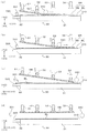
次に、上記のように構成された剥離装置1による剥離動作について、図6ないし図8を参照しながら説明する。図6は剥離処理を示すフローチャートである。また、図7および図8は処理中の各段階における各部の位置関係を示す図であり、処理の進行状況を模式的に表したものである。この剥離処理は、CPU701が予め記憶された処理プログラムを実行して各部を制御することによりなされる。
Next, the peeling operation by the peeling apparatus 1 configured as described above will be described with reference to FIGS. FIG. 6 is a flowchart showing the peeling process. FIG. 7 and FIG. 8 are diagrams showing the positional relationship of each part at each stage during processing, and schematically show the progress of processing. This peeling process is performed by the
まず、オペレータまたは外部の搬送ロボット等によってワークWKがステージ30上の上記位置にロードされると(ステップS101)、装置が初期化されて装置各部が所定の初期状態に設定される(ステップS102)。初期状態では、ワークWKが吸着溝311,312の一方または両方によって吸着保持され、初期剥離ユニット33の押圧部材331、ローラユニット34の剥離ローラ340、第1ないし第4吸着ユニット51〜54の吸着パッド517〜547はいずれもワークWKから離間している。また剥離ローラ340はその可動範囲において最も(−Y)側に寄った位置にある。
First, when the workpiece WK is loaded at the above position on the
この状態から、第1吸着ユニット51および剥離ローラ340を下降させて、それぞれワークWKの上面に当接させる(ステップS103)。このとき、図7(a)に示すように、第1吸着ユニット51の吸着パッド517が基板SBの(−Y)側端部の上面を吸着し、剥離ローラ340はその(+Y)側隣接位置で基板SBの上面に当接する。図7(a)において押圧部材331の近傍に付した下向き矢印は、図に示される状態から、続く工程では押圧部材331が当該矢印方向に移動することを意味している。以下の図においても同様である。
From this state, the
図4に示される領域R3はこの時に第1吸着ユニット51により基板SBが吸着される領域を示し、領域R4は剥離ローラ340が基板SBに当接する領域を示す。図4に示すように、第1吸着ユニット51は基板SBの(−Y)側端部を吸着保持する一方、剥離ローラ340は第1吸着ユニット51による吸着領域R3の(+Y)側に隣接する領域R4で基板SBに当接する。剥離ローラ340が当接する当接領域R4は、有効領域ARよりも外側、つまり有効領域ARから(−Y)側に寄った位置とされる。したがって、有効領域ARの内部は第1吸着ユニット51による吸着、剥離ローラ340による押圧のいずれをも受けていない。
A region R3 shown in FIG. 4 indicates a region where the substrate SB is sucked by the
図6に戻って、次に初期剥離ユニット33を作動させ、押圧部材331を下降させてブランケットBL端部を押圧する(ステップS104)。ブランケットBLの端部はテーパーステージ部32の上方に突出しており、その下面とテーパーステージ32の上面320との間には隙間がある。したがって、図7(b)に示すように、押圧部材331がブランケットBLの端部を下方へ押圧することにより、ブランケットBLの端部がテーパーステージ部32のテーパー面に沿って下方へ屈曲する。その結果、第1吸着ユニット51により吸着保持される基板SBの端部とブランケットBLとの間が離間し剥離が開始される。押圧部材331はX方向に延びる棒状に形成され、しかもそのX方向長さがブランケットBLよりも長く設定されている。したがって、図4に示すように、押圧部材331がブランケットBLに当接する当接領域R5は、ブランケットBLの(−X)側端部から(+X)側端部まで直線状に延びる。こうすることで、ブランケットBLを柱面状に屈曲させることができ、基板SBとブランケットBLとが既に剥離した剥離領域と、まだ剥離していない未剥離領域との境界線(以下、「剥離境界線」という)を直線状にすることができる。
Returning to FIG. 6, next, the
この状態から、第1吸着ユニット51の上昇を開始するとともに、これと同期させて剥離ローラ340を(+Y)方向に向けて移動させる(ステップS105)。具体的には、第1吸着ユニット51の上昇により(+Y)方向に移動する剥離境界線が剥離ローラ340の直下に到達するタイミングで、剥離ローラ340の移動を開始する。これにより図4に示す当接領域R4は(+Y)方向に移動してゆく。この後、第1吸着ユニット51は上方、つまり(+Z)方向に、また剥離ローラ340は(+Y)方向に、それぞれ一定速度で移動する。
From this state, the
図7(c)に示すように、基板SBの端部を保持する第1吸着ユニット51が上昇することで基板SBが引き上げられてブランケットBLとの剥離が(+Y)方向に向かって進行するが、剥離ローラ340を当接させているため、剥離ローラ340による当接領域R4(図4)を超えて剥離が進行することはない。剥離ローラ340を基板SBに当接させながら一定速度で(+Y)方向に移動させることで、剥離の進行速度を一定に維持することができる。すなわち、剥離境界線がローラ延設方向つまりX方向に沿った一直線となり、しかも一定速度で(+Y)方向に進行する。これにより、剥離の進行速度の変動による応力集中に起因するパターンの損傷を確実に防止することができる。
As shown in FIG. 7C, when the
続いて、以下の処理のための内部的な制御パラメータNの値を2に設定する(ステップS106)。そして、剥離ローラ340が第N吸着位置を通過するのを待つ(ステップS107)。第N吸着位置は、基板SB上面のうち第N吸着ユニット(N=1〜4)の直下位置であり、当該第N吸着ユニットによる吸着を受ける位置である。
Subsequently, the value of the internal control parameter N for the following processing is set to 2 (step S106). Then, the process waits for the peeling
ここではN=2であるので、剥離ローラ340が第2吸着位置、つまり第2吸着ユニット52の直下位置を通過するまで待つ。剥離ローラ340が第2吸着位置を通過すると(ステップS107においてYES)、第2吸着ユニット52の下降を開始し、第2吸着ユニット52の吸着パッド527により基板SBを捕捉する(ステップS108)。
Since N = 2 here, the process waits until the peeling
図7(d)に示すように、剥離ローラ340が既に通過していることから、第2吸着ユニット52の直下位置では基板SBはブランケットBLから剥離して上方へ浮き上がった状態となっている。伸縮性を有する弾性部材で構成された吸着パッド527に負圧を付与しながら基板SBに近付けてゆくことで、吸着パッド527の下面が基板SBの上面に当接した時点で基板SBを捕捉し吸着することができる。吸着パッド527を所定位置まで下降させた後、引き上げられてくる基板SBを待機する態様であってもよい。いずれにおいても、吸着パッドに柔軟性を持たせることで、吸着の失敗を防止することができる。
As shown in FIG. 7D, since the peeling
基板SBの吸着を開始した後、第2吸着ユニット52の移動を上昇に転じる(ステップS109)。これにより、図8(a)に示すように、剥離の進行速度は依然として剥離ローラ340により制御されつつ、剥離のための基板SBの引き上げの主体は第1吸着ユニット51から第2吸着ユニット52に引き継がれる。また剥離後の基板SBは、第1吸着ユニット51のみによる保持から第1吸着ユニット51と第2吸着ユニット52とによる保持に切り替わり、保持箇所が増加することになる。なお、各吸着ユニット51〜54が上昇する際、剥離後の基板SBの姿勢が略平面となるように、各吸着ユニット51〜54間のZ方向における相対位置が維持される。
After the suction of the substrate SB is started, the movement of the
続いて制御パラメータNの値に1が加えられて(ステップS111)、処理はパラメータNが4となるまでステップS107に戻るループ処理となる。したがって次のループでは、剥離ローラ340が第3吸着ユニット53直下の第3吸着位置を通過した時点で第3吸着ユニット53の下降が開始され、図8(b)に示すように、剥離のための基板SBの引き上げの主体が第2吸着ユニット52から第3吸着ユニット53に移行する。さらに次のループでは剥離ローラ340が第4吸着位置を通過した後に第4吸着ユニット54が下降し、基板SBを引き上げる。ステップS110におけるNの上限値を変更することで、吸着ユニットの数が上記と異なる場合にも対応可能である。
Subsequently, 1 is added to the value of the control parameter N (step S111), and the process is a loop process that returns to step S107 until the parameter N becomes 4. Therefore, in the next loop, when the peeling
こうして第4吸着ユニット54によって基板SBが引き上げられることで、図8(c)に示すように、基板SBの全体がブランケットBLから引き離される。そこで、第4吸着ユニット54を上昇させた後(ステップS110においてYES)、剥離ローラ340をステージ30よりも(+Y)側まで移動させてその移動を停止させる(ステップS112)。そして、図8(d)に示すように、各吸着ユニット51〜54を全て同じ高さまで上昇させた後に停止させる(ステップS113)。また、初期剥離ユニット33の押圧部材331をブランケットBLから離間させ、ブランケットBLの上面より上方かつブランケットBLの(−Y)側端部よりも(−Y)側の退避位置まで移動させる(ステップS114)。その後、吸着溝によるブランケットBLの吸着保持を解除し、分離された基板SBおよびブランケットBLを装置外へ搬出することで(ステップS115)、剥離処理が完了する。
Thus, by pulling up the substrate SB by the
各吸着ユニット51〜54の高さを同じとするのは、剥離後の基板SBとブランケットBLとを平行に保持することで、外部ロボットまたはオペレータにより挿入される払い出し用ハンドのアクセスと、それへのブランケットBLおよび基板SBの受け渡しとを容易にするためである。
The
以上のように、この実施形態では、剥離の進行方向(ここではY方向)に直交するX方向に延設された剥離ローラ340を基板SBに当接させ、剥離ローラ340を剥離の進行方向に一定速度で移動させながら基板SBを引き上げることにより、剥離の進行速度を一定に保って基板SBとブランケットBLとの間を良好に剥離させることができる。このとき、本実施形態の剥離処理では、次のような利点が得られる。
As described above, in this embodiment, the peeling
図9は本実施形態における剥離処理の利点を説明するための図である。本実施形態では、基板SBを引き上げる主体を順次剥離進行方向の下流側にある吸着ユニットに移行させてゆく。このため、剥離の初期から最終段階まで、剥離ローラ340の直下における基板SBの曲率はある一定の範囲内で推移する。そのため、図9(a)に示すように、既に剥離した部分の基板SBとブランケットBLとがなす角αも一定範囲内に収まる。このため、剥離した部分と未剥離の部分との境界、すなわち剥離ローラ340直下の剥離境界線において基板SBとブランケットBLとを引き離す力(剥離力)も概ね一定である。したがってパターンを損傷することなく良好に剥離を進行させることができる。
FIG. 9 is a diagram for explaining the advantage of the peeling process in the present embodiment. In the present embodiment, the main body that pulls up the substrate SB is sequentially transferred to the suction unit on the downstream side in the peeling progress direction. For this reason, from the initial stage to the final stage of peeling, the curvature of the substrate SB just below the peeling
これに対して、基板SBの一端部のみを保持して引き上げる比較例を考えると、図9に示すように、基板SBの剛性や質量にもよるが、剥離が進むにつれて自重による基板SBの撓み量が大きくなり、基板SBの引き上げが撓みにより吸収されて剥離の進行が鈍る。すなわち、剥離境界線近傍における基板SBとブランケットBLとがなす角βが次第に小さくなり、両者の間に生じる剥離力が小さくなって剥離の進行が遅くなる。 On the other hand, considering a comparative example in which only one end portion of the substrate SB is held and pulled up, as shown in FIG. 9, depending on the rigidity and mass of the substrate SB, the substrate SB bends due to its own weight as the peeling progresses. The amount increases, and the pulling up of the substrate SB is absorbed by the bending, and the progress of the peeling is slowed down. That is, the angle β formed between the substrate SB and the blanket BL in the vicinity of the peeling boundary line is gradually reduced, and the peeling force generated between the two is reduced, so that the peeling progress is delayed.
より甚だしい場合には、吸着ユニットによる吸着力が基板SBの質量を支えきれなくなって基板SBが落下したり、基板SBが曲げに耐えられずに割れたり折れ曲がってしまうなどの問題が生じる。また、基板SB全体をブランケットBLから引き離すために必要な基板SBの引き上げ量が大きくなり、これを可能にするための装置構成の大型化を招くことにもなる。特に基板SBの大型化が進むと基板SBの質量が大きくなるため、これらの問題はさらに顕著となる。 In a more severe case, there arises a problem that the adsorption force by the adsorption unit cannot support the mass of the substrate SB and the substrate SB falls, or the substrate SB cannot withstand bending and is broken or bent. In addition, the amount of pulling up the substrate SB required to separate the entire substrate SB from the blanket BL increases, and this leads to an increase in the size of the apparatus configuration for enabling this. In particular, as the size of the substrate SB increases, the mass of the substrate SB increases, and these problems become more prominent.
一方、この実施形態では、剥離の進行に伴って基板SBの保持箇所を順次増加させることで基板SBの保持を確実にするとともに、剥離後の基板SBの姿勢を容易に維持することが可能となる。そして、上記のように安定した剥離力を与えつつ剥離を進行させることができるので、パターンの損傷も防止される。また基板SBのサイズに応じて吸着ユニットを配置することにより、基板SBの大型化にも柔軟に対応することが可能である。 On the other hand, in this embodiment, the holding position of the substrate SB is sequentially increased as the peeling progresses, whereby the holding of the substrate SB is ensured and the posture of the substrate SB after peeling can be easily maintained. Become. And since peeling can be advanced, giving the stable peeling force as mentioned above, damage to a pattern is also prevented. Further, by arranging the suction unit according to the size of the substrate SB, it is possible to flexibly cope with the increase in the size of the substrate SB.
また、この実施形態では、図4に示すように、剥離の初期段階で基板SBの引き上げを担う第1吸着ユニット51により基板SBが吸着される領域R3は、有効なパターンが形成された有効領域ARよりも外側である。基板SBが局所的に吸着されることによりその部分で基板SBが部分的にブランケットBLから剥離し、これによりパターンが変形したり損傷するなどの影響が生じる可能性があるが、有効領域外を吸着することで、このような問題は回避される。また、剥離境界線が剥離ローラ340の直下位置に到達するまでは剥離速度が不安定となるが、同様に初期段階における剥離ローラ340の当接領域R4を有効領域外とすることで、剥離速度の変動に起因するパターンの損傷も防止される。
Further, in this embodiment, as shown in FIG. 4, the region R3 on which the substrate SB is adsorbed by the
一方、剥離の進行中に新たに基板SBを吸着する第2ないし第4吸着ユニット52〜54は、ブランケットBLから既に剥離した領域において基板SBと当接するため、この場合の吸着によって基板SBに転写されたパターンを傷めることはない。
On the other hand, the second to
以上説明したように、この実施形態においては、剥離対象物たるワークWKのうちブランケットBLが本発明の「第1板状体」に相当する一方、基板SBが本発明の「第2板状体」に相当している。また、基板SBの(−Y)側端部が本発明の「一端部」に相当し、これとは反対側の(+Y)側端部が本発明の「他端部」に相当する。そして、(+Y)方向が本発明の「剥離進行方向」に相当する。 As described above, in this embodiment, the blanket BL corresponds to the “first plate-like body” of the present invention and the substrate SB of the present invention is the “second plate-shaped body” of the workpiece WK as the separation target. Is equivalent to. The (−Y) side end of the substrate SB corresponds to “one end” of the present invention, and the (+ Y) side end opposite to this corresponds to the “other end” of the present invention. The (+ Y) direction corresponds to the “peeling progress direction” of the present invention.
また、この実施形態では、ステージ30が本発明の「保持手段」として機能しており、そのうち水平ステージ部31の上面310が本発明の「保持面」として機能している。また、この実施形態では、第1吸着ユニット51が本発明の「第1剥離手段」として機能する一方、第2ないし第4吸着ユニット52〜54がそれぞれ本発明の「第2剥離手段」として機能している。そして、吸着パッド527等が本発明の「当接部位」に相当している。また、剥離ローラ340が本発明の「当接手段」として機能しており、図4における当接領域R4の位置が本発明における「当接開始位置」に相当している。
In this embodiment, the
なお、本発明は上記した実施形態に限定されるものではなく、その趣旨を逸脱しない限りにおいて上述したもの以外に種々の変更を行うことが可能である。例えば、上記実施形態ではステージ30に格子状の吸着溝311,312を設けてブランケットBLを吸着保持しているが、吸着溝の形状はこれに限定されない。例えば環状の吸着溝を設けてもよく、また負圧が供給される吸着孔を適宜配置してブランケットを吸着してもよい。
The present invention is not limited to the above-described embodiment, and various modifications other than those described above can be made without departing from the spirit of the present invention. For example, in the above embodiment, the lattice-shaped
また、上記実施形態では、剥離後の基板SBの姿勢を平面に近い状態に維持するように各吸着ユニット51〜54の上昇が制御されて基板SBに加わるストレスが低減されているが、基板SBの引き上げの態様はこれに限定されない。例えば、剥離後の基板が略水平となるように各吸着ユニットを一定高さで停止させたり、あるいは基板が所定の曲率を持って湾曲するような姿勢に保持するようにしてもよい。これらは各吸着ユニットの上昇の態様を制御することによって自由に設定可能である。 Moreover, in the said embodiment, although the raise of each adsorption | suction unit 51-54 is controlled so that the attitude | position of the board | substrate SB after peeling is maintained in the state close | similar to a plane, the stress added to the board | substrate SB is reduced. The manner of pulling up is not limited to this. For example, each suction unit may be stopped at a certain height so that the substrate after peeling is substantially horizontal, or may be held in such a posture that the substrate is curved with a predetermined curvature. These can be freely set by controlling the rising mode of each adsorption unit.
また、上記実施形態では4つの吸着ユニットを基板SB上部に配置して順次基板SBを吸着しているが、吸着ユニットの数はこれに限定されるものではなく任意である。基板が大型であれば吸着ユニットを多く、小型であれば少なくすればよい。剥離の初期の段階で基板を保持する第1剥離手段と、これよりも剥離進行方向の下流側で剥離後の基板を保持する少なくとも1つの第2剥離手段とを有する構成は、本発明の技術思想の範疇に包含される。 In the embodiment described above, four suction units are arranged on the substrate SB and sequentially suck the substrates SB. However, the number of suction units is not limited to this and is arbitrary. If the substrate is large, the number of suction units may be increased, and if the substrate is small, it may be decreased. The configuration having the first peeling means for holding the substrate at the initial stage of peeling and at least one second peeling means for holding the substrate after peeling on the downstream side in the peeling progress direction is a technique of the present invention. Included in the category of thought.
また、上記実施形態では真空吸着によって基板およびブランケットを保持しているが、保持の態様はこれに限定されない。例えば静電的または磁気的な吸着力により吸着保持するものであってもよい。特に基板の有効領域外を保持する第1剥離手段については、吸着によらず、基板周縁部を機械的に把持することにより保持してもよい。 Moreover, although the board | substrate and the blanket are hold | maintained by vacuum suction in the said embodiment, the aspect of holding | maintenance is not limited to this. For example, it may be attracted and held by electrostatic or magnetic attracting force. In particular, the first peeling means for holding the outside of the effective area of the substrate may be held by mechanically gripping the peripheral edge of the substrate without being attracted.
また、上記実施形態ではテーパーステージ部32にブランケットBLを突き出させて保持し、押圧部材331によりブランケットBLを屈曲させて剥離のきっかけを作っているが、このようにすることは必須の要件ではなく、例えば第1吸着ユニットの引き上げのみで剥離を開始させるようにしてもよい。この場合、ステージにテーパーを設ける必要はなくなる。
Further, in the above embodiment, the blanket BL is protruded and held on the
この発明は、2枚の板状体を密着させてパターン等を転写させるパターン形成処理における剥離プロセスに適用することができるほか、このようなパターン転写を伴うものに限らず、互いに密着した2枚の板状体を良好に剥離する種々の目的に対して好適に適用可能である。 The present invention can be applied to a peeling process in a pattern forming process in which two plates are brought into close contact with each other to transfer a pattern or the like. This can be suitably applied to various purposes for satisfactorily peeling the plate-like body.
1 剥離装置
30 ステージ(保持手段)
31 水平ステージ部(保持手段)
32 テーパーステージ部(保持手段)
51 第1吸着ユニット(第1剥離手段)
52〜54 第2ないし第4吸着ユニット(第2剥離手段)
310 (水平ステージ部31の)上面(保持面)
340 剥離ローラ(当接手段)
517 吸着パッド
527,537,547 吸着パッド(当接部位)
BL ブランケット(第1板状体)
R4 当接開始位置
SB 基板(第2板状体)
1 Peeling
31 Horizontal stage (holding means)
32 Tapered stage (holding means)
51 1st adsorption | suction unit (1st peeling means)
52-54 2nd thru | or 4th adsorption | suction unit (2nd peeling means)
310 Upper surface (holding surface) of the
340 Peeling roller (contact means)
517
BL blanket (first plate)
R4 Contact start position SB substrate (second plate)
Claims (13)
前記第1板状体のうち前記薄膜またはパターンが形成された有効領域の平面サイズよりも大きい保持面を有し、該保持面に前記第1板状体の表面のうち前記第2板状体と密着した面とは反対側の面を当接させて前記第1板状体を保持する保持手段と、
前記第2板状体の一端部を保持しながら前記保持手段から離間する方向に移動して、前記第2板状体の前記一端部を前記第1板状体から剥離させる第1剥離手段と、
前記第2板状体の前記一端部から該一端部と反対側の他端部に向かう剥離進行方向に直交する方向に前記第2板状体に沿って延設されたローラ状に形成され、前記剥離進行方向における前記一端部の下流側に隣接する当接開始位置で、前記第1板状体と密着した面とは反対側の前記第2板状体の一方面に当接するとともに、前記第2板状体に当接しながら前記当接開始位置から前記他端部に向けて前記剥離進行方向に移動する当接手段と、
前記剥離方向における前記当接開始位置の下流側で前記第2板状体の前記一方面に臨んで設けられ、前記当接手段が通過した後の前記第2板状体の前記一方面に部分的に当接して前記第2板状体を保持しながら前記保持手段から離間する方向に移動する第2剥離手段と
を備える剥離装置。 In the peeling apparatus for peeling the first plate and the second plate that are in close contact with each other through a thin film or pattern,
The first plate-like body has a holding surface larger than the plane size of the effective area where the thin film or pattern is formed, and the second plate-like body among the surfaces of the first plate-like body is provided on the holding surface. Holding means for holding the first plate-like body by contacting a surface opposite to the surface in close contact with,
A first peeling means that moves in a direction away from the holding means while holding one end portion of the second plate-like body, and peels the one end portion of the second plate-like body from the first plate-like body; ,
It is formed in a roller shape extending along the second plate-like body in a direction perpendicular to the peeling progress direction from the one end portion of the second plate-like body to the other end portion on the opposite side to the one end portion, At the contact start position adjacent to the downstream side of the one end portion in the peeling progress direction, the first plate-like body is in contact with one surface of the second plate-like body on the opposite side of the surface, and A contact means that moves in the peeling progress direction from the contact start position toward the other end while contacting the second plate-like body;
Provided facing the one surface of the second plate-like body on the downstream side of the contact start position in the peeling direction, and partially on the one surface of the second plate-like body after the contact means has passed And a second peeling means that moves in a direction away from the holding means while holding the second plate-like body in contact with each other.
前記第1板状体のうち前記薄膜またはパターンが形成された有効領域の平面サイズよりも大きい保持面に前記第1板状体の表面のうち前記第2板状体と密着した面とは反対側の面を当接させて前記第1板状体を保持する工程と、
前記第2板状体の一端部から該一端部と反対側の他端部に向かう剥離進行方向における前記一端部の下流側に隣接する当接開始位置で、前記第1板状体と密着した面とは反対側の前記第2板状体の一方面に、前記剥離進行方向に直交する方向に延設されたローラ状の当接手段を当接させる工程と、
前記第2板状体の一端部を前記第1板状体から離間する方向に移動させて、前記第2板状体の前記一端部を前記第1板状体から剥離させるとともに、前記当接手段を前記第2板状体に当接させながら前記当接開始位置から前記他端部に向けて前記剥離進行方向に移動させる工程と、
前記当接手段を移動させながら、前記剥離方向における前記当接開始位置の下流側で、前記当接手段が通過し前記第1板状体から剥離した後の前記第2板状体の前記一方面を部分的に保持しながら前記第1板状体から離間する方向に移動させる工程と
を備える剥離方法。 In the peeling method of peeling the first plate and the second plate that are in close contact with each other through a thin film or pattern,
The surface of the first plate is opposite to the surface of the first plate that is in close contact with the second plate on the holding surface that is larger than the plane size of the effective area on which the thin film or pattern is formed. Holding the first plate-like body by contacting the side surface;
At the contact start position adjacent to the downstream side of the one end in the peeling progress direction from one end of the second plate to the other end opposite to the one end, the second plate contacts the first plate Contacting one surface of the second plate-like body opposite to the surface with roller-shaped contact means extending in a direction perpendicular to the peeling progress direction;
The one end of the second plate is moved away from the first plate to separate the one end of the second plate from the first plate, and the contact Moving the means in the peeling progress direction from the contact start position toward the other end while contacting the second plate-like body;
While moving the contact means, on the downstream side of the contact start position in the peeling direction, the one of the second plate-like bodies after the contact means passes and peels from the first plate-like body. And a step of moving in a direction away from the first plate-like body while partially holding the direction.
Priority Applications (4)
| Application Number | Priority Date | Filing Date | Title |
|---|---|---|---|
| JP2013063862A JP6047439B2 (en) | 2013-03-26 | 2013-03-26 | Peeling apparatus and peeling method |
| TW102145972A TWI529066B (en) | 2013-03-26 | 2013-12-12 | Detaching apparatus and detaching method |
| KR20130161417A KR101489094B1 (en) | 2013-03-26 | 2013-12-23 | Detaching apparatus and detaching method |
| CN201410108252.6A CN104070779B (en) | 2013-03-26 | 2014-03-21 | Stripping off device and stripping means |
Applications Claiming Priority (1)
| Application Number | Priority Date | Filing Date | Title |
|---|---|---|---|
| JP2013063862A JP6047439B2 (en) | 2013-03-26 | 2013-03-26 | Peeling apparatus and peeling method |
Publications (2)
| Publication Number | Publication Date |
|---|---|
| JP2014189350A JP2014189350A (en) | 2014-10-06 |
| JP6047439B2 true JP6047439B2 (en) | 2016-12-21 |
Family
ID=51592575
Family Applications (1)
| Application Number | Title | Priority Date | Filing Date |
|---|---|---|---|
| JP2013063862A Active JP6047439B2 (en) | 2013-03-26 | 2013-03-26 | Peeling apparatus and peeling method |
Country Status (4)
| Country | Link |
|---|---|
| JP (1) | JP6047439B2 (en) |
| KR (1) | KR101489094B1 (en) |
| CN (1) | CN104070779B (en) |
| TW (1) | TWI529066B (en) |
Families Citing this family (21)
| Publication number | Priority date | Publication date | Assignee | Title |
|---|---|---|---|---|
| JP6246605B2 (en) * | 2014-01-28 | 2017-12-13 | 株式会社Screenホールディングス | Peeling apparatus and peeling method |
| JP6398622B2 (en) * | 2014-11-06 | 2018-10-03 | オムロン株式会社 | Peeling apparatus and peeling method |
| KR102437397B1 (en) * | 2014-11-19 | 2022-08-30 | 코닝 인코포레이티드 | Apparatus and method of peeling a multi-layer substrate |
| JP6393596B2 (en) * | 2014-11-19 | 2018-09-19 | リンテック株式会社 | Alignment apparatus and alignment method |
| JP6345109B2 (en) * | 2014-12-26 | 2018-06-20 | 株式会社Screenホールディングス | Peeling method and peeling device |
| JP6471606B2 (en) * | 2015-02-23 | 2019-02-20 | Agc株式会社 | Laminate peeling apparatus, peeling method, and electronic device manufacturing method |
| JP6468462B2 (en) * | 2015-02-23 | 2019-02-13 | Agc株式会社 | Laminate peeling apparatus, peeling method, and electronic device manufacturing method |
| KR101865686B1 (en) * | 2015-03-24 | 2018-06-08 | 동우 화인켐 주식회사 | Method and manufacturing apparatus for film touch sensor |
| JP6419619B2 (en) * | 2015-03-24 | 2018-11-07 | 株式会社Screenホールディングス | Method for creating a peeling device recipe |
| JP6450238B2 (en) | 2015-03-31 | 2019-01-09 | 株式会社Screenホールディングス | Peeling device |
| JP6519951B2 (en) * | 2015-07-24 | 2019-05-29 | 日本電気硝子株式会社 | METHOD FOR MANUFACTURING GLASS FILM, AND METHOD FOR MANUFACTURING ELECTRONIC DEVICE INCLUDING GLASS FILM |
| KR102106379B1 (en) * | 2016-03-23 | 2020-05-04 | 야마하 모터 로보틱스 홀딩스 가부시키가이샤 | Peeling device |
| JP2018043377A (en) * | 2016-09-13 | 2018-03-22 | 株式会社Screenホールディングス | Peeling device and peeling method |
| EP3541627A1 (en) * | 2016-11-15 | 2019-09-25 | Corning Incorporated | Methods for processing a substrate |
| KR102331075B1 (en) * | 2017-03-17 | 2021-11-25 | 주식회사 케이씨텍 | Substrate procesing apparatus |
| JP7115490B2 (en) * | 2017-09-20 | 2022-08-09 | 日本電気硝子株式会社 | Glass substrate manufacturing method |
| JP7033310B2 (en) * | 2018-04-27 | 2022-03-10 | 三星ダイヤモンド工業株式会社 | Scrap removal mechanism and scrap removal method |
| JP7641087B2 (en) * | 2018-12-20 | 2025-03-06 | 日本電気硝子株式会社 | Glass film manufacturing method and manufacturing apparatus, and manufacturing method for electronic device including glass film |
| CN109809217B (en) * | 2019-03-20 | 2021-03-26 | 深圳精智达技术股份有限公司 | Flexible panel material distribution device and method |
| CN113715466B (en) * | 2021-08-31 | 2023-06-06 | 艾尔玛科技股份有限公司 | Manufacturing device and process of nano texture transfer printing decoration panel |
| CN113921449A (en) * | 2021-10-12 | 2022-01-11 | 苏州遂芯半导体科技有限公司 | A wafer debonding equipment |
Family Cites Families (12)
| Publication number | Priority date | Publication date | Assignee | Title |
|---|---|---|---|---|
| JP3592214B2 (en) * | 2000-08-10 | 2004-11-24 | 有限会社田辺塗工所 | Hydraulic transfer method and hydraulic transfer apparatus for long objects |
| US20040013966A1 (en) * | 2001-06-22 | 2004-01-22 | Yoshiharu Sasaki | Method and apparatus for recording image |
| JP2003072123A (en) | 2001-06-22 | 2003-03-12 | Fuji Photo Film Co Ltd | Recording method and recorder |
| JP3810714B2 (en) | 2002-07-29 | 2006-08-16 | エスペック株式会社 | Thin layer substrate manufacturing method, thin layer substrate transfer device, and thin layer substrate transfer suction pad |
| JP2007320678A (en) * | 2006-05-30 | 2007-12-13 | Fujifilm Corp | Method and device for peeling outer layer body |
| JP4957375B2 (en) * | 2007-05-16 | 2012-06-20 | ソニー株式会社 | Organic EL display device manufacturing equipment |
| JP2009214392A (en) * | 2008-03-10 | 2009-09-24 | Mitsubishi Paper Mills Ltd | Support body for ink jet recording material, its manufacturing method, and ink jet recording material using it |
| JP2009239071A (en) | 2008-03-27 | 2009-10-15 | Dainippon Screen Mfg Co Ltd | Peeling device |
| JP4602442B2 (en) * | 2008-07-31 | 2010-12-22 | 日本写真印刷株式会社 | Sheet with static elimination function, sheet static elimination system, and pattern simultaneous molding method, printing method and vapor deposition method using sheet with static elimination function |
| KR100990738B1 (en) * | 2008-08-14 | 2010-10-29 | 서판수 | Transfer type printing method and apparatus and printed matter produced thereby |
| KR101254418B1 (en) * | 2009-08-31 | 2013-04-15 | 아사히 가라스 가부시키가이샤 | Peeling device |
| TWI585028B (en) * | 2013-01-30 | 2017-06-01 | 斯克林集團公司 | Detaching apparatus and detaching method |
-
2013
- 2013-03-26 JP JP2013063862A patent/JP6047439B2/en active Active
- 2013-12-12 TW TW102145972A patent/TWI529066B/en not_active IP Right Cessation
- 2013-12-23 KR KR20130161417A patent/KR101489094B1/en active IP Right Grant
-
2014
- 2014-03-21 CN CN201410108252.6A patent/CN104070779B/en not_active Expired - Fee Related
Also Published As
| Publication number | Publication date |
|---|---|
| KR101489094B1 (en) | 2015-02-02 |
| CN104070779A (en) | 2014-10-01 |
| KR20140117253A (en) | 2014-10-07 |
| TWI529066B (en) | 2016-04-11 |
| JP2014189350A (en) | 2014-10-06 |
| CN104070779B (en) | 2016-08-03 |
| TW201437030A (en) | 2014-10-01 |
Similar Documents
| Publication | Publication Date | Title |
|---|---|---|
| JP6047439B2 (en) | Peeling apparatus and peeling method | |
| KR101512590B1 (en) | Detaching apparatus and detaching method | |
| KR101541643B1 (en) | Detaching apparatus | |
| JP6055705B2 (en) | Transfer apparatus and transfer method | |
| KR101771838B1 (en) | Detaching apparatus | |
| US20180071771A1 (en) | Detaching apparatus and detaching method | |
| JP6246605B2 (en) | Peeling apparatus and peeling method | |
| JP6207857B2 (en) | Peeling apparatus and peeling method | |
| JP6153334B2 (en) | Peeling apparatus and peeling method | |
| JP6047438B2 (en) | Peeling apparatus and peeling method | |
| JP2016179892A (en) | Recipe preparing method for peeling device | |
| JP2016010922A (en) | Peeling device, peeling method and pattern forming device | |
| JP2018043515A (en) | Peeling device and peeling method | |
| JP6131077B2 (en) | Transfer peeling apparatus, transfer peeling method and pattern forming system | |
| JP2016064526A (en) | Pattern carrier, and producing method and producing device of pattern carrier |
Legal Events
| Date | Code | Title | Description |
|---|---|---|---|
| A621 | Written request for application examination |
Free format text: JAPANESE INTERMEDIATE CODE: A621 Effective date: 20160218 |
|
| TRDD | Decision of grant or rejection written | ||
| A01 | Written decision to grant a patent or to grant a registration (utility model) |
Free format text: JAPANESE INTERMEDIATE CODE: A01 Effective date: 20161115 |
|
| A977 | Report on retrieval |
Free format text: JAPANESE INTERMEDIATE CODE: A971007 Effective date: 20161117 |
|
| A61 | First payment of annual fees (during grant procedure) |
Free format text: JAPANESE INTERMEDIATE CODE: A61 Effective date: 20161121 |
|
| R150 | Certificate of patent or registration of utility model |
Ref document number: 6047439 Country of ref document: JP Free format text: JAPANESE INTERMEDIATE CODE: R150 |
|
| R250 | Receipt of annual fees |
Free format text: JAPANESE INTERMEDIATE CODE: R250 |
|
| R250 | Receipt of annual fees |
Free format text: JAPANESE INTERMEDIATE CODE: R250 |
|
| R250 | Receipt of annual fees |
Free format text: JAPANESE INTERMEDIATE CODE: R250 |
|
| R250 | Receipt of annual fees |
Free format text: JAPANESE INTERMEDIATE CODE: R250 |
|
| R250 | Receipt of annual fees |
Free format text: JAPANESE INTERMEDIATE CODE: R250 |
|
| R250 | Receipt of annual fees |
Free format text: JAPANESE INTERMEDIATE CODE: R250 |