JP6045913B2 - Lanyard and personal emergency transmitter system - Google Patents
Lanyard and personal emergency transmitter system Download PDFInfo
- Publication number
- JP6045913B2 JP6045913B2 JP2012522286A JP2012522286A JP6045913B2 JP 6045913 B2 JP6045913 B2 JP 6045913B2 JP 2012522286 A JP2012522286 A JP 2012522286A JP 2012522286 A JP2012522286 A JP 2012522286A JP 6045913 B2 JP6045913 B2 JP 6045913B2
- Authority
- JP
- Japan
- Prior art keywords
- coupling means
- flexible cord
- lanyard
- lanyard device
- coupled
- Prior art date
- Legal status (The legal status is an assumption and is not a legal conclusion. Google has not performed a legal analysis and makes no representation as to the accuracy of the status listed.)
- Expired - Fee Related
Links
- 230000008878 coupling Effects 0.000 claims description 97
- 238000010168 coupling process Methods 0.000 claims description 97
- 238000005859 coupling reaction Methods 0.000 claims description 97
- 238000000926 separation method Methods 0.000 claims description 15
- 238000001514 detection method Methods 0.000 claims description 3
- 206010003497 Asphyxia Diseases 0.000 description 6
- 208000027418 Wounds and injury Diseases 0.000 description 1
- 230000005540 biological transmission Effects 0.000 description 1
- 239000004020 conductor Substances 0.000 description 1
- 230000008094 contradictory effect Effects 0.000 description 1
- 239000004744 fabric Substances 0.000 description 1
- 239000000696 magnetic material Substances 0.000 description 1
- 239000000463 material Substances 0.000 description 1
- 230000013011 mating Effects 0.000 description 1
- 238000005204 segregation Methods 0.000 description 1
Images


Classifications
-
- A—HUMAN NECESSITIES
- A45—HAND OR TRAVELLING ARTICLES
- A45B—WALKING STICKS; UMBRELLAS; LADIES' OR LIKE FANS
- A45B5/00—Walking sticks or umbrellas convertible into seats; Hunting sticks
-
- A—HUMAN NECESSITIES
- A45—HAND OR TRAVELLING ARTICLES
- A45F—TRAVELLING OR CAMP EQUIPMENT: SACKS OR PACKS CARRIED ON THE BODY
- A45F5/00—Holders or carriers for hand articles; Holders or carriers for use while travelling or camping
-
- F—MECHANICAL ENGINEERING; LIGHTING; HEATING; WEAPONS; BLASTING
- F16—ENGINEERING ELEMENTS AND UNITS; GENERAL MEASURES FOR PRODUCING AND MAINTAINING EFFECTIVE FUNCTIONING OF MACHINES OR INSTALLATIONS; THERMAL INSULATION IN GENERAL
- F16G—BELTS, CABLES, OR ROPES, PREDOMINANTLY USED FOR DRIVING PURPOSES; CHAINS; FITTINGS PREDOMINANTLY USED THEREFOR
- F16G11/00—Means for fastening cables or ropes to one another or to other objects; Caps or sleeves for fixing on cables or ropes
- F16G11/10—Quick-acting fastenings; Clamps holding in one direction only
-
- A—HUMAN NECESSITIES
- A45—HAND OR TRAVELLING ARTICLES
- A45F—TRAVELLING OR CAMP EQUIPMENT: SACKS OR PACKS CARRIED ON THE BODY
- A45F3/00—Travelling or camp articles; Sacks or packs carried on the body
- A45F2003/002—Sacks or packs carried on the body by means of a single strap passing around the neck
-
- A—HUMAN NECESSITIES
- A45—HAND OR TRAVELLING ARTICLES
- A45F—TRAVELLING OR CAMP EQUIPMENT: SACKS OR PACKS CARRIED ON THE BODY
- A45F5/00—Holders or carriers for hand articles; Holders or carriers for use while travelling or camping
- A45F2005/006—Holders or carriers for hand articles; Holders or carriers for use while travelling or camping comprising a suspension strap or lanyard
-
- A—HUMAN NECESSITIES
- A45—HAND OR TRAVELLING ARTICLES
- A45F—TRAVELLING OR CAMP EQUIPMENT: SACKS OR PACKS CARRIED ON THE BODY
- A45F5/00—Holders or carriers for hand articles; Holders or carriers for use while travelling or camping
- A45F5/004—Holders or carriers for hand articles; Holders or carriers for use while travelling or camping with an automatic spring reel
Landscapes
- Engineering & Computer Science (AREA)
- General Engineering & Computer Science (AREA)
- Mechanical Engineering (AREA)
- Emergency Lowering Means (AREA)
- Alarm Systems (AREA)
- Helmets And Other Head Coverings (AREA)
- Accommodation For Nursing Or Treatment Tables (AREA)
Description
本発明は、ランヤードデバイス及びこのランヤードデバイスを有する緊急応答システムに関する。 The present invention relates to a lanyard device and an emergency response system having the lanyard device.
仕事場において多くの人々は、両手が必要で、他のアイテムが手の届く範囲に保たれなければならないような作業を遂行する。斯かるアイテムを手の届く範囲に保つため、このアイテムは、ランヤードデバイスに付けられることができる。ランヤードデバイスは、人の首周辺で小さな対象物を固定又は下げるのに通常使用される小さなコード又はロープである。ランヤードデバイスは、安全でアクセスしやすい位置に重要なアイテムを格納及び/又は搬送するのに有益である。 Many people in the workplace perform tasks that require both hands and that other items must be kept within reach. In order to keep such an item within reach, this item can be attached to the lanyard device. A lanyard device is a small cord or rope typically used to secure or lower small objects around a person's neck. Lanyard devices are useful for storing and / or transporting important items in a secure and accessible location.
US2004/0232010号は、第1の端部及び第2の端部を含む調節可能な分離可能なランヤードデバイスを開示する。ここで、第1及び第2の端部は、所定の力が保持手段に印可されるとき、選択的に分離されることができる保持手段を含む。この選択的な分離は、着用者に対する窒息の危険を防止するため、ランヤードデバイス自体が分離することを可能にする。不利な点は、分離する際、ランヤードデバイス及びこれに付けられる小さな対象物が、落下することがあり、着用者の手の届かない所に行く場合がある点にある。 US 2004/0232010 discloses an adjustable separable lanyard device that includes a first end and a second end. Here, the first and second ends include holding means that can be selectively separated when a predetermined force is applied to the holding means. This selective separation allows the lanyard device itself to separate to prevent the risk of suffocation for the wearer. The disadvantage is that when separating, the lanyard device and small objects attached to it can fall and go out of reach of the wearer.
本発明の目的は、保持手段の分離後でも、着用者の手の届く範囲に残るランヤードデバイスを提供することである。 It is an object of the present invention to provide a lanyard device that remains within the reach of the wearer even after separation of the holding means.
本発明の目的は、請求項1に記載のランヤードデバイスで実現される。本発明は、既知の分離可能なランヤードデバイスが1つのリスクだけを想定しているという洞察に基づかれる。それは、絞扼のリスク又は着用者の首が危険な態様で引っ張られるリスクである。既知の分離可能ランヤードデバイスは、着用者に容易にアクセス可能なランヤードデバイスに付けられるアイテムが分離後はもはや存在しないことに関連付けられる何らかのリスク又は危険を反映するものではない。これは、セキュリティ又は緊急通信デバイスがラニヤードに付けられるような場合である。本発明によるランヤードデバイスにおいて、第1及び第2の結合手段に結合される第2の柔軟なコードが、ランヤードデバイスが着用者から分離され、手の届く範囲外になることを防止する。ランヤードデバイスにより形成されるループは、着用者の首を囲む。作用する所定の力の結果として、第1及び第2の結合手段が分離した後、ループの長さは、第1の柔軟なコードの長さから第1の柔軟なコード+第2の柔軟なコードの長さへと増加する。第2の柔軟なコードの追加的に利用可能な長さは、絞扼又は着用者の首の危険な引っ張りのリスクを最小化する。同時に、第2の柔軟なコードが第1及び第2の結合手段の間に結合されるので、ランヤードデバイスは、第1及び第2の結合手段の分離後であっても着用者の手の届く範囲にとどまる。 The object of the present invention is realized by a lanyard device according to claim 1. The present invention is based on the insight that known separable lanyard devices assume only one risk. It is the risk of strangulation or the risk of the wearer's neck being pulled in a dangerous manner. Known separable lanyard devices do not reflect any risks or dangers associated with the fact that items attached to lanyard devices that are readily accessible to the wearer no longer exist after segregation. This is the case when a security or emergency communication device is attached to the lanyard. In the lanyard device according to the present invention, the second flexible cord coupled to the first and second coupling means prevents the lanyard device from being separated from the wearer and out of reach. The loop formed by the lanyard device surrounds the wearer's neck. As a result of the predetermined force acting, after the first and second coupling means are separated, the loop length is changed from the first flexible cord length to the first flexible cord + second flexible cord. Increase to the length of the cord. The additional available length of the second flexible cord minimizes the risk of strangulation or dangerous pulling of the wearer's neck. At the same time, since the second flexible cord is coupled between the first and second coupling means, the lanyard device can be reached by the wearer even after separation of the first and second coupling means. Stay in range.
第1の柔軟なコードは、例えばその対応する端部にフック及びループファスナを持つフラットケーブルの形状を持つことができる。フック及びループファスナの例は、ベルクロ(登録商標)の名で知られる。フック及びループファスナは、着脱可能に結合されることができる第1及び第2の結合手段の例である。第1の柔軟なコードに作用する所定の力が、フック及びループファスナが分離することをもたらす。結果として、着用者の首を囲むループの長さは、第1の柔軟なコードの長さから第1の柔軟なコード+第2の柔軟なコードの長さへと増加する。フラットケーブルは例えば、編み織物で作られることができる。ランヤードデバイスの別の実施形態では、第1の柔軟なコード及び/又は第2の柔軟なコードが、リボン、ひも材又はケーブルから作られる。 The first flexible cord can have the shape of a flat cable with hook and loop fasteners at its corresponding ends, for example. Examples of hook and loop fasteners are known under the name Velcro®. Hook and loop fasteners are examples of first and second coupling means that can be detachably coupled. A predetermined force acting on the first flexible cord causes the hook and loop fastener to separate. As a result, the length of the loop surrounding the wearer's neck increases from the length of the first flexible cord to the length of the first flexible cord plus the second flexible cord. The flat cable can be made of knitted fabric, for example. In another embodiment of the lanyard device, the first flexible cord and / or the second flexible cord are made from a ribbon, string or cable.
ランヤードデバイスの実施形態において、第2の柔軟なコードの長さは、上記ランヤードデバイスを首周りに着用する人の身長の2倍であり、好ましくは、上記人の身長の2倍から上記第1の柔軟なコードの長さを引いたものより少なくとも大きい。この長さは、ランヤードデバイスを着用する人が転倒しても第2の柔軟なコードが緊張することがなく、転倒においてランヤードデバイスが何らかの対象物に捕えられるという利点を持つ。こうして、第1及び第2の結合手段への張力の印可が、それらの分離をもたらす。 In an embodiment of the lanyard device, the length of the second flexible cord is twice the height of the person wearing the lanyard device around the neck, preferably from twice the height of the person to the first. Is at least larger than the flexible cord minus the length. This length has the advantage that even if the person wearing the lanyard device falls, the second flexible cord does not become tense, and the lanyard device is caught by some object in the fall. Thus, the application of tension to the first and second coupling means results in their separation.
ランヤードデバイスの更なる実施形態において、上記第2の柔軟なコードが、上記第1又は第2の結合手段に着脱可能に結合される。これは、移動する対象物にランヤードがもつれる場合、第2の柔軟なコードが着用者を窒息させることがないという利点をもたらす。これは更に、作用する更なる所定の力の下で第2のコードが分離する場合に、ランヤードが容易に再利用されることができるという利点を与える。 In a further embodiment of the lanyard device, the second flexible cord is detachably coupled to the first or second coupling means. This provides the advantage that the second flexible cord does not suffocate the wearer if the moving object is tangled. This further provides the advantage that the lanyard can be easily reused when the second cord separates under a further predetermined force acting.
更なる実施形態では、着用者の首があまりに大きな力で引っ張られることを防止するため、作用する更なる所定の力の下で、第2の柔軟なコードが破壊するよう、第2の柔軟なコードの付着が構成される。上記実施形態において、第2の柔軟なコードの抗張力又は第1若しくは第2の結合手段に対する第2の柔軟なコードの結合の強度は好ましくは、上記更なる所定の力が上記所定の力より小さいよう構成されることができる。その結果、第2の柔軟なコードが原因による絞扼のリスクは最小化される。また、別の実施形態では、第1及び第2の結合手段の分離をもたらす上記所定の力が、着用者の首を引っ張るのに許される最大の力に対応するよう、第1及び第2の結合手段の結合が構成される。 In a further embodiment, the second flexible cord is broken so that the second flexible cord breaks under an additional predetermined force acting to prevent the wearer's neck from being pulled with too much force. Code attachment is configured. In the above embodiment, the tensile strength of the second flexible cord or the strength of the second flexible cord coupling to the first or second coupling means is preferably such that the further predetermined force is less than the predetermined force. Can be configured as follows. As a result, the risk of strangulation due to the second flexible code is minimized. In another embodiment, the first and second forces are such that the predetermined force resulting in the separation of the first and second coupling means corresponds to the maximum force allowed to pull the wearer's neck. A coupling of coupling means is configured.
更なる実施形態において、第1の柔軟なコードは、人の首を囲むのに適したループにおいて構成される。上記第1の柔軟なコードは更に、着脱可能に結合されるよう構成される第3及び第4の結合手段を有する。第3及び第4の結合手段は、ランヤードデバイスが頭の上に引っ張り上げられる必要なしに、着用者の首周りでのランヤードの容易なフィットを可能にする。第3及び第4の結合手段は、例えば「スナップ」フィットでもよい。 In a further embodiment, the first flexible cord is configured in a loop suitable to enclose the person's neck. The first flexible cord further includes third and fourth coupling means configured to be detachably coupled. The third and fourth coupling means allow an easy fit of the lanyard around the wearer's neck without having to pull the lanyard device over the head. The third and fourth coupling means may be a “snap” fit, for example.
更なる実施形態において、第1の結合手段は更に、第2のコードが巻き付けられるとき、この第2の柔軟なコードを格納する手段を有する。格納手段は、第2の柔軟なコードを格納し、斯かるコードが損傷する又は外部対象物により捕えられることから保護するのに便利な場所を与える。 In a further embodiment, the first coupling means further comprises means for storing the second flexible cord when the second cord is wound. The storage means stores a second flexible code and provides a convenient place to protect such code from being damaged or caught by external objects.
更なる実施形態において、第1の結合手段は更に、第2の柔軟なコードをスプールするよう構成されるスプーリング手段を有する。スプーリング手段は、第2の柔軟なコードを格納するのに便利な場所を与える。 In a further embodiment, the first coupling means further comprises spooling means configured to spool the second flexible cord. The spooling means provides a convenient place to store the second flexible code.
更なる実施形態において、スプーリング手段は、第1の結合手段に格納される。これは、第1の結合手段の囲いがスプーリング手段を保護するという利点を与える。 In a further embodiment, the spooling means is stored in the first coupling means. This provides the advantage that the enclosure of the first coupling means protects the spooling means.
更なる実施形態において、スプーリング手段は、第1の結合手段に取り付けられて回転可能であるスプールを有する。ばねは、第2の柔軟なコードがスプールされることをもたらすようスプール上で作用する。これにより、第2の柔軟なコードがしっかり引っ張られる状態が保たれる。第1及び第2の結合手段が結合されるとき、ばねの力は第2の柔軟なコードがスプールされることをもたらす。これは、第1及び第2の結合手段を分離することにより、ループの長さが容易に長くされることができる利点を与える。これは、ランヤードデバイスを頭の上に引っ張りあげることを容易にする。その後、ループの長さは、第1及び第2の結合手段の結合により、再び容易に短くされる。ここで、ばねの力は、第2の柔軟なコードがスプールされることをもたらす。 In a further embodiment, the spooling means has a spool attached to the first coupling means and rotatable. The spring acts on the spool to cause the second flexible cord to be spooled. Thereby, the state in which the second flexible cord is pulled firmly is maintained. When the first and second coupling means are coupled, the spring force causes the second flexible cord to be spooled. This provides the advantage that the length of the loop can be easily increased by separating the first and second coupling means. This makes it easy to pull the lanyard device over the head. Thereafter, the length of the loop is easily shortened again by the coupling of the first and second coupling means. Here, the force of the spring causes the second flexible cord to be spooled.
本発明の更なる実施形態において、個人緊急応答システムが、本発明のランヤードデバイスに付けられる。上記個人緊急応答システムは、例えばボタンを押すことにより、着用者が助けを呼ぶことを可能にする携帯型無線デバイスを有する。本発明によるランヤードデバイスは、第1及び第2の結合手段が分離する場合でも個人緊急応答システムが手の届く範囲外に行かないという利点を与える。例えば、個人緊急応答システムが、ユーザが救助要請を行うことを可能にする通信デバイスの付いたランヤードデバイスを有することができる。上記システムは、ユーザの首周りのペンダントとして着用される。ユーザが転倒する場合、ランヤードデバイスに含まれるコードが何らかの対象物に捕らえられ、これが、第1及び第2の結合手段により形成される安全解放機能に印加される張力をもたらす。保持手段がない場合、個人緊急応答システムは、着用者から何らかの距離分放り出される可能性がある。これでは、ユーザはシステムにアクセスすることができない。本発明のランヤードデバイスでは、第1及び第2の結合手段に付けられる第2の柔軟なコードにより保持手段が形成される。保持手段は、転倒後であってもユーザのすぐ近くに通信デバイスを留め、ユーザが救助要請することを可能にする。 In a further embodiment of the present invention, a personal emergency response system is attached to the lanyard device of the present invention. The personal emergency response system has a portable wireless device that allows the wearer to call for help, for example by pressing a button. The lanyard device according to the invention provides the advantage that the personal emergency response system does not go out of reach even when the first and second coupling means are separated. For example, a personal emergency response system can have a lanyard device with a communication device that allows a user to make a rescue request. The system is worn as a pendant around the user's neck. When the user falls, the cord contained in the lanyard device is captured by some object, which results in tension applied to the safety release function formed by the first and second coupling means. In the absence of holding means, the personal emergency response system may be thrown away some distance from the wearer. This prevents the user from accessing the system. In the lanyard device of the present invention, the holding means is formed by the second flexible cord attached to the first and second coupling means. The holding means keeps the communication device in the immediate vicinity of the user even after a fall and allows the user to request a rescue.
更なる実施形態において、上記システムは、転倒検出手段を有することができる。転倒を検出する場合、携帯型無線デバイスが、救助要請を送信するよう構成される。 In a further embodiment, the system may have a fall detection means. If a fall is detected, the portable wireless device is configured to send a rescue request.
更なる実施形態において、上記システムは、第2の柔軟なコードの破壊又は分離を検出し、第2の柔軟なコードの破壊又は分離が検出されるとき、救助要請を送信するよう構成されることができる。 In a further embodiment, the system is configured to detect a second flexible code break or separation and send a rescue request when a second flexible code break or separation is detected. Can do.
本発明の好ましい実施形態が、例示にすぎないものを介して、図面を参照して、以下に説明されることになる。 Preferred embodiments of the invention will now be described, by way of example only, with reference to the drawings.
既知のランヤードデバイスは、例えばIDカード又は鍵といったアイテムをこのアイテムが付けられるコードを用いて首周りに着用するのに使用される。これらのランヤードデバイスは、着用者が何らかのデバイスに捕えられるという絞扼が起こる危険を避けるため、安全解放機能を持つことができる。この安全解放機能は、張力がコードに印可される場合、これを開かせる。この開放は、例えばUS6,826,806に開示される分離可能な閉鎖デバイスで実現されることができる。 Known lanyard devices are used to wear items such as ID cards or keys around the neck using a code to which the item is attached. These lanyard devices can have a safety release feature to avoid the risk of strangling that the wearer is trapped by some device. This safety release function causes the cord to open when tension is applied to the cord. This opening can be achieved with a separable closure device as disclosed, for example, in US 6,826,806.
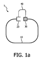
図1aは、第1及び第2の結合手段20、30を有するランヤードデバイス5を示す。この第1及び第2の結合手段は、互いに接続されることができる例えば嵌合部分である。これらの部分は、例えば互いにスナップしてフィットする、又は摩擦ベースの結合を持つ、弾力的又は変形可能なプラスチックとすることができる。第1及び第2の結合手段は、別の例では、フック及びループファスナを用いて実現されることができる。また、更なる例では、第1及び第2の結合手段は磁気物質を有することができる。その結果、これらの第1及び第2の結合手段は互いに引きつけられる。第1及び第2の結合手段は更に、互いに着脱可能に結合されるよう構成される。その結果、所定の力がそれらの上で作用するとき、これらは分離し、これにより、分離可能な閉鎖デバイスが形成される。ランヤードデバイスに付けられるアイテムが、ランヤードデバイスに対して移動する対象物ともつれる場合、この所定の力は例えば第1の柔軟なコード10上で作用することができる。第1の柔軟なコードは、第1及び第2の結合手段20、30にこの所定の力を伝え、それらが分離されることをもたらす。例えばフック及びループファスナは、それらの上で作用する力の結果として切り離されることができる。また、第1及び第2の磁気結合手段は、磁気引力より大きい力がそれらの上で作用するとき分離することができる。この例では、第1及び第2の結合手段上に作用する所定の力は、分離を生じさせるため、より大きな磁気引力でなければならない。これは、磁石を必要な大きさにすることにより着用者の首に対する最大引力を制限することを可能にする。なぜなら、磁石を必要な大きさにすることで、第1及び第2の結合手段20、30の磁気引力が決定されることができるからである。ランヤードデバイス5は、第1及び第2の結合手段20、30に対してその端部で結合される第1の柔軟なコード10を有する。本発明によるランヤードデバイスは、第1及び第2の結合手段20、30に対してその端部で結合される第2の柔軟なコード40を更に有する。所定の力の結果として第1及び第2の結合手段が分離するとき、着用者の首を囲むコードの長さは、第1の柔軟なコード10及び第2の柔軟なコード40の長さの合計にまで増加する。こうして、従来技術のランヤードデバイスとは異なり、本発明によるランヤードデバイスは、張力がランヤードデバイスに印加される場合、首を囲んだまま残り、従って、着用者の近くに留まる。こうして、ランヤードデバイスに付けられる重要なアイテムは手の届く範囲にとどまり、アイテムが失われるというリスクが低減される。本発明によるランヤードデバイスにおいて、第1及び第2の結合手段により実現される安全解放機能が、ランヤード上の危険な張力を解放するよう構成される。一方、第2の柔軟なコードが、保持機能を実現する。これは、ランヤードデバイスが、着用者の首周りに保たられることをもたらし、従って、ランヤードデバイスに付けられるアイテムが使用のためアクセス可能な状態に保たれる。第2の柔軟なコードは、保持手段の例である。
FIG. 1 a shows a
図1bは、第3及び第4の結合手段25、35を有するランヤードデバイス5の更なる実施形態を示す。この実施形態は、ランヤードデバイスの第1及び第2の柔軟なコード10、40により形成されるループの開放により、ランヤードデバイス5が、人の首周りに容易に置かれることができるという利点を持つ。図1aのランヤードデバイスで必要とされるように、これは頭の上にランヤードデバイスを引き上げるより便利である。第3及び第4の結合手段は、第1及び第2の結合手段と類似するタイプとすることができ、印加された張力の結果として分離することができる。しかしながら、第3及び第4の結合手段も安全解放機能を持つ場合、それらは、第1及び第2の結合手段20、30の前に分離しないよう構成されるべきである。
FIG. 1 b shows a further embodiment of the
図2は、図1aのランヤードデバイスの更なる実施形態を示す。この場合、その端部に付けられるフック及びループファスナ20、30を持つリボン10として第1の柔軟なコードは実現される。この実施形態において、第2の柔軟なコード40は、リボンの端部に接続され、第1及び第2の結合手段には接続されない。
FIG. 2 shows a further embodiment of the lanyard device of FIG. In this case, the first flexible cord is realized as a
図3aは、第2の柔軟なコード40を格納する一体化されたスプーリング手段50、60を備える第1の結合手段20を持つランヤードデバイス5の更なる実施形態を示す。スプーリング手段は、スプール上で作用するばね60の力の結果として、第2の柔軟なコードを緊張下に保つよう構成される回転可能なスプールを有する。ばねの力により生成される張力は、第1及び第2の結合手段20、30上で作用するとき、それらが分離することをもたらす所定の力より小さいよう構成される。第2のコード40がかなりの長さ(例えばランヤードデバイスを着用する人の身長の2倍)を持つので、スプール50上に格納されるとき、これは便利で安全である。図3bにおいて、第1及び第2の結合手段20、30が結合される限り、第2の柔軟なコード40は、第1の結合手段20において巻きつけられ、及び格納される。巻き付けられた第2の柔軟なコード52が、第1の結合手段20に対して1つの端部53で付けられ、他端が、第2の結合手段30に結合される。第1及び第2の結合手段上で作用する所定の力の結果として、第1及び第2の結合手段が分離するとき、第2の柔軟なコードが、第1の囲み手段から引き出される。
FIG. 3 a shows a further embodiment of the
図4aは、嵌合部分として実現される第1及び第2の結合手段20、30を持つランヤードデバイスの更なる実施形態を示す。これらの部分は、第2の結合手段30の拡張部が第1の結合手段20の空腔において押されることを可能にする例えば変形可能な物質でできている。拡張部及び空腔は、フィットを実現するよう対応する形状を持つ。この結合は、「スナップ」フィットを生じさせる。拡張部及び空腔の形状を必要な大きさにすることにより、安全解放機能は実現されることができる。結合された後、第1及び第2の結合手段は、第1又は第2の結合手段上に作用する所定の力の結果として分離されることができる。第1及び第2の結合手段は更に、第1の柔軟なコードを実現するリボン10に結合される。第1の結合手段20は、ケーブル40を格納するスプーリング手段50を有する。ケーブルの1つの端部は、スプーリング手段に含まれるスプールに結合され、ケーブルの他端は、第2の結合手段30に着脱可能に結合される。ケーブル40は、第2の柔軟なコードの例示的な実施形態である。
FIG. 4a shows a further embodiment of a lanyard device with first and second coupling means 20, 30 realized as a mating part. These parts are made of a deformable material, for example, which allows the extension of the second coupling means 30 to be pushed in the cavity of the first coupling means 20. The extension and the cavity have corresponding shapes to achieve a fit. This bond produces a “snap” fit. A safety release function can be realized by making the shape of the extension and the cavity the required size. After being coupled, the first and second coupling means can be separated as a result of a predetermined force acting on the first or second coupling means. The first and second coupling means are further coupled to a
図4bは、図4aのランヤードデバイスを示す。ここで、ケーブルは、第1及び第2の結合手段20、30上に作用する更なる所定の力の結果として、第2の結合手段30から分離する。ランヤードデバイスの着用者の絞扼を防止するために第1及び第2の結合手段が分離されるとき、ケーブル40が現れることになる。ケーブルが完全に現れるとき、更なる所定の力が第1又は第2の結合手段をまだ引いている場合、これは第2の結合手段30から分離されることができる。この分離は、所定の力が着用者の首を引くことを防止する。第2の結合手段30が第1の結合手段20において押されるとき、それらは再び結合されることになる。ケーブル40の他端も、再び第2の結合手段30に結合されることになる。
FIG. 4b shows the lanyard device of FIG. 4a. Here, the cable separates from the second coupling means 30 as a result of a further predetermined force acting on the first and second coupling means 20, 30. The
図5は、人200が助けを呼ぶことを可能にする携帯型無線デバイス110を有する個人緊急応答システム100を示す。携帯型デバイス110は、このデバイスが人の首周りに着用されることを可能にする本発明のランヤードデバイス5に結合される。これは、必要なときに、介護者に助けを求めるか又は介護者と通信することを可能にする。携帯型無線デバイス110は、例えば押されるとき救助要請が介護者に送信されるヘルプボタン120を有することができる。携帯型無線デバイスは更に、例えばFM送信機といった送信手段130を有する。更なる実施形態において、第1及び第2の柔軟なコード10、40は、導電性ループを生じさせる導電性物質を有する。これは、第2の柔軟なコード40の分離又は破壊によりもたらされるループの開放の電子的検出を可能にする。このループの開放は、可能性として危険な状況又は事件が原因で、個人緊急応答システムがもう着用者の近くにないことを示すことができる。ループの開放を検出すると、個人緊急応答システム100は、救助要請を送信することができる。
FIG. 5 shows a personal
図6は、本発明によるランヤードデバイス10及び携帯型無線デバイス110を有する個人緊急応答システム100を着用する人200を示す。携帯型無線デバイス110は、例えば携帯電話といった例えば通信デバイスとすることができる。現在、個人緊急システムのデザイナーは、ランヤードデバイス上に安全解放機能を組み込まないことからの絞扼のリスクが、安全解放機能が起動される場合に着用者が助けを呼ぶことができないリスクを上回るかどうかを考慮しなければならない。本発明によるランヤードデバイスを用いると、これらの一見反する要件が満たされることができる。安全解放機能は、絞扼の危険度を最小化する。一方、同時に、安全解放機能が起動される場合でも、保持機能が、携帯型無線デバイスを着用者に利用可能な状態に保つ。
FIG. 6 shows a
要約すると、本発明のランヤードデバイス5は、着脱可能に結合されることができる第1及び第2の結合手段20、30に結合される第1のコード10を有する。第1のコードは、ユーザの200の首周りに着用されることができるループにおいて構成される。第1及び第2の結合手段は、所定の力が第1のコード上で作用するとき、ループを開放することにより絞扼のリスクを最小化する安全解放機能を実現する。ランヤードデバイスは更に、解放機能が起動される場合でも、このランヤードデバイスに付けられる通信デバイス110をユーザの近くに保つ保持機能を有する。保持機能は、第1及び第2の結合手段に結合される第2のコード40により実現されることができる。
In summary, the
本発明が図面及び前述の説明において詳細に図示され及び説明されたが、斯かる図示及び説明は、説明的又は例示的であると考えられ、本発明を限定するものではない。本発明は、開示された実施形態に限定されるものではない。 While the invention has been illustrated and described in detail in the drawings and foregoing description, such illustration and description are to be considered illustrative or exemplary and not restrictive. The invention is not limited to the disclosed embodiments.
図面、開示及び添付された請求項の研究から、開示された実施形態に対する他の変形が、請求項に記載の発明を実施する当業者により理解され、実行されることができる。請求項において、単語「有する」は他の要素又はステップを除外するものではなく、不定冠詞「a」又は「an」は複数性を除外するものではない。請求項における任意の参照符号は、範囲を限定するものとみなされるべきではない。 From studying the drawings, disclosure and appended claims, other variations to the disclosed embodiments can be understood and implemented by those skilled in the art practicing the claimed invention. In the claims, the word “comprising” does not exclude other elements or steps, and the indefinite article “a” or “an” does not exclude a plurality. Any reference signs in the claims should not be construed as limiting the scope.
Claims (14)
第1の端部及び第2の端部を持つ第1の柔軟なコードと、
第1及び第2の結合手段であって、前記第1の結合手段が前記第1の端部に結合され、前記第2の結合手段は前記第2の端部に結合されるよう構成される第1及び第2の結合手段とを有し、
前記第1の結合手段が更に、前記第2の結合手段に着脱可能に直接結合されるよう構成され、前記第1及び第2の結合手段上で作用する所定の力の結果として、前記第1及び第2の結合手段は分離されるよう更に構成され、
前記ランヤードデバイスが更に、前記第1の結合手段及び第2の結合手段を結合する第2の柔軟なコードを有する、ランヤードデバイス。 A lanyard device,
A first flexible cord having a first end and a second end;
First and second coupling means, wherein the first coupling means is coupled to the first end, and the second coupling means is coupled to the second end. First and second coupling means;
The first coupling means is further configured to be detachably coupled directly to the second coupling means, and as a result of a predetermined force acting on the first and second coupling means, the first coupling means And the second coupling means is further configured to be separated,
The lanyard device further comprises a second flexible cord for coupling the first coupling means and the second coupling means.
前記第2の柔軟なコードの長さは、前記人の身長の2倍から前記第1の柔軟なコードの長さを引いたものより少なくとも大きい、請求項1に記載のランヤードデバイス。 The length of the second flexible cord is twice the height of the person wearing the lanyard device around the neck;
The lanyard device of claim 1, wherein a length of the second flexible cord is at least greater than twice the height of the person minus the length of the first flexible cord.
前記デバイスが、前記人が救助を要請することを可能にする手段を有し、
前記デバイスは更に、介護者に救助要請を送信するよう構成される送信手段を有し、
前記デバイスが、請求項1乃至11の任意の一項に記載のランヤードデバイスに結合される、個人緊急応答システム。 A personal emergency response system having a portable wireless device that allows a person to call for help,
The device comprises means for allowing the person to request rescue;
The device further comprises transmitting means configured to transmit a rescue request to the caregiver;
12. A personal emergency response system, wherein the device is coupled to a lanyard device according to any one of claims 1-11.
Applications Claiming Priority (3)
| Application Number | Priority Date | Filing Date | Title |
|---|---|---|---|
| EP09166541.4 | 2009-07-28 | ||
| EP09166541 | 2009-07-28 | ||
| PCT/IB2010/053267 WO2011013026A1 (en) | 2009-07-28 | 2010-07-19 | Lanyard and personal emergency transmitter system |
Publications (2)
| Publication Number | Publication Date |
|---|---|
| JP2013500112A JP2013500112A (en) | 2013-01-07 |
| JP6045913B2 true JP6045913B2 (en) | 2016-12-14 |
Family
ID=42768053
Family Applications (1)
| Application Number | Title | Priority Date | Filing Date |
|---|---|---|---|
| JP2012522286A Expired - Fee Related JP6045913B2 (en) | 2009-07-28 | 2010-07-19 | Lanyard and personal emergency transmitter system |
Country Status (9)
| Country | Link |
|---|---|
| US (1) | US9386829B2 (en) |
| EP (1) | EP2459027B1 (en) |
| JP (1) | JP6045913B2 (en) |
| CN (1) | CN102469870B (en) |
| AU (1) | AU2010277246B2 (en) |
| BR (1) | BR112012001765B1 (en) |
| PL (1) | PL2459027T3 (en) |
| RU (1) | RU2531895C2 (en) |
| WO (1) | WO2011013026A1 (en) |
Families Citing this family (11)
| Publication number | Priority date | Publication date | Assignee | Title |
|---|---|---|---|---|
| GB201107228D0 (en) * | 2011-04-29 | 2011-06-15 | Hathaway Mark | Sail release safety mechanism to prevent capsize or demasting |
| US9059777B2 (en) * | 2011-09-15 | 2015-06-16 | Casey SHATTUCK | Lanyard |
| WO2013152037A1 (en) * | 2012-04-02 | 2013-10-10 | Rizzi Arthur | Carriers for mobile devices |
| US9805577B2 (en) | 2013-11-05 | 2017-10-31 | Nortek Security & Control, LLC | Motion sensing necklace system |
| US10143892B2 (en) * | 2014-04-12 | 2018-12-04 | Black Diamond Equipment, Ltd. | Cam stem system |
| KR200476999Y1 (en) * | 2014-12-22 | 2015-04-23 | 이상국 | Musical instrument supporter |
| CN107111924B (en) | 2014-12-22 | 2019-11-26 | 皇家飞利浦有限公司 | Personal emergency responding device and personal emergency response system including it |
| US11208183B2 (en) * | 2015-06-02 | 2021-12-28 | Acr Electronics, Inc. | EPIRB having retention carriage strap for hands free carriage |
| CN106291598A (en) * | 2015-06-11 | 2017-01-04 | 孔晓波 | A kind of alignment system to animal protection and monitoring method thereof |
| WO2018144007A1 (en) * | 2017-02-03 | 2018-08-09 | Hewlett-Packard Development Company, L.P. | Lanyard attachment for an input device |
| GB2623783A (en) * | 2022-10-26 | 2024-05-01 | Tunstall Integrated Health & Care Ltd | Neckband strain relief device |
Family Cites Families (30)
| Publication number | Priority date | Publication date | Assignee | Title |
|---|---|---|---|---|
| US3819177A (en) | 1972-01-31 | 1974-06-25 | I Spiro | Elastic exercise belt |
| AU569604B2 (en) * | 1984-01-31 | 1988-02-11 | Vital Communications Pty. Ltd. | Alarm transmitter housing |
| US5533238A (en) | 1994-10-31 | 1996-07-09 | Say; James | Breakaway cord connector |
| US5669242A (en) * | 1995-03-16 | 1997-09-23 | Cayton; Meryl L. | Necklace extension accessory |
| JP3412659B2 (en) * | 1995-06-22 | 2003-06-03 | ワイケイケイ株式会社 | Long object connector |
| JPH09305875A (en) * | 1996-05-10 | 1997-11-28 | Omron Corp | Fall detection device, receiving device and notification system using them |
| US6073317A (en) | 1997-08-19 | 2000-06-13 | Barison; Joseph I. | Lanyard breakaway connector |
| US6281800B1 (en) * | 1999-05-19 | 2001-08-28 | Edric Sizemore | Personal security backpack |
| US6539588B1 (en) | 1999-10-04 | 2003-04-01 | Comprehensive Identification Products, Inc. | Breakaway lanyard with adjustable mounting element |
| US6666647B1 (en) | 2001-07-20 | 2003-12-23 | Russell B. Trask | Neck fan for personal cooling |
| US20030121125A1 (en) | 2001-12-11 | 2003-07-03 | Comprehensive Identification Products, Inc. | Breakaway gripper-style lanyard connector |
| US6826806B2 (en) | 2002-05-24 | 2004-12-07 | Illinois Tool Works Inc. | Breakaway closure device |
| US20040232010A1 (en) | 2002-08-07 | 2004-11-25 | Thomason Rodger D. | Adjustable breakaway lanyard |
| US20040032333A1 (en) * | 2002-08-19 | 2004-02-19 | Hatt Alfred Thomas | Personal security wrist band |
| US6615460B1 (en) | 2002-08-27 | 2003-09-09 | David Baumgarten | Optionally manual or automatic breakaway lanyard buckle |
| US20040056061A1 (en) | 2002-09-25 | 2004-03-25 | Bill Yang | Neck strap of portable apparatus |
| US7168275B2 (en) * | 2004-12-28 | 2007-01-30 | Alpha Security Products, Inc. | Cable wrap security device |
| US20060219741A1 (en) * | 2005-04-05 | 2006-10-05 | Clark Carolyn M | Clasp assembly system for bracelets and necklaces |
| JP2006296743A (en) * | 2005-04-20 | 2006-11-02 | Hokuto:Kk | Strap fastening tool |
| WO2007011336A1 (en) | 2005-07-14 | 2007-01-25 | Ykk Corporation Of America | Shock absorbing lanyards |
| US7712643B2 (en) * | 2005-10-05 | 2010-05-11 | Karen Papernik | Jewelry fastening aid |
| JP2007213533A (en) * | 2006-02-08 | 2007-08-23 | Jupiter Net:Kk | Ultraminiature portable emergency notification device |
| ITPD20070019A1 (en) * | 2007-01-19 | 2008-07-20 | Silmar Spa | MAGNETIC CLOSING DEVICE FOR ORNAMENTAL CHAINS |
| EP1970510A1 (en) * | 2007-03-13 | 2008-09-17 | MW Security AB | Security device |
| US20080250616A1 (en) * | 2007-04-10 | 2008-10-16 | Katydid Accessories | Jewelry Clasp |
| US20100206925A1 (en) * | 2007-07-23 | 2010-08-19 | Fielding Jr Jerry | Lanyard assembly for audio device |
| US20090120130A1 (en) * | 2007-11-14 | 2009-05-14 | Mabra Crystal L | Retractable Jewelry Fastener |
| US20090316109A1 (en) * | 2008-06-20 | 2009-12-24 | Karl Hellberg | Modular retainer and coupling system and method of use |
| WO2010030869A2 (en) * | 2008-09-13 | 2010-03-18 | Michele Mccauley | Personal security device |
| US20100133307A1 (en) * | 2008-11-13 | 2010-06-03 | Charlie Martin | Lanyard with pocket |
-
2010
- 2010-07-19 JP JP2012522286A patent/JP6045913B2/en not_active Expired - Fee Related
- 2010-07-19 RU RU2012107167/12A patent/RU2531895C2/en active
- 2010-07-19 EP EP10740376.8A patent/EP2459027B1/en active Active
- 2010-07-19 WO PCT/IB2010/053267 patent/WO2011013026A1/en active Application Filing
- 2010-07-19 PL PL10740376T patent/PL2459027T3/en unknown
- 2010-07-19 US US13/381,985 patent/US9386829B2/en active Active
- 2010-07-19 BR BR112012001765A patent/BR112012001765B1/en not_active IP Right Cessation
- 2010-07-19 AU AU2010277246A patent/AU2010277246B2/en not_active Ceased
- 2010-07-19 CN CN201080032806.9A patent/CN102469870B/en not_active Expired - Fee Related
Also Published As
| Publication number | Publication date |
|---|---|
| AU2010277246B2 (en) | 2015-02-12 |
| RU2012107167A (en) | 2013-09-10 |
| RU2531895C2 (en) | 2014-10-27 |
| EP2459027A1 (en) | 2012-06-06 |
| US20120105223A1 (en) | 2012-05-03 |
| CN102469870A (en) | 2012-05-23 |
| US9386829B2 (en) | 2016-07-12 |
| PL2459027T3 (en) | 2017-06-30 |
| BR112012001765A8 (en) | 2017-09-19 |
| BR112012001765B1 (en) | 2019-12-31 |
| WO2011013026A1 (en) | 2011-02-03 |
| EP2459027B1 (en) | 2016-12-14 |
| JP2013500112A (en) | 2013-01-07 |
| BR112012001765A2 (en) | 2017-05-09 |
| CN102469870B (en) | 2014-10-22 |
| AU2010277246A1 (en) | 2012-03-22 |
Similar Documents
| Publication | Publication Date | Title |
|---|---|---|
| JP6045913B2 (en) | Lanyard and personal emergency transmitter system | |
| US8482401B2 (en) | Safety belt and system for checking a usage status of the safety belt | |
| US20160058130A1 (en) | Multi-purpose closure system | |
| US20060272890A1 (en) | Lanyard electronic message device | |
| JP4917730B2 (en) | Lead with ergonomic handle | |
| US20100165286A1 (en) | Retainears | |
| CN101535160A (en) | Stick-on security ring for a hand held device | |
| US10069951B2 (en) | Mobile phone case apparatus and system | |
| EP3500774B1 (en) | Lanyard for a tool | |
| CN102726850A (en) | Safety jacket, in particular fire safety jacket with an integrated belt | |
| US20090106944A1 (en) | Safety device for ring-like accessories | |
| JP2004105420A (en) | Strap for mobile device | |
| CN114306976A (en) | Intelligent hook, intelligent safety rope and safety realization method | |
| CN218446939U (en) | Hanging rope for preventing mobile phone from being lost | |
| KR20220064670A (en) | Dog lead wire device | |
| CN215380747U (en) | Pet haulage rope | |
| US20170104302A1 (en) | Wrapped electrical cable | |
| TWM572121U (en) | Pet leash with warning function | |
| KR102453765B1 (en) | Ear free mask necklace | |
| KR102554885B1 (en) | Heart Rate-Based Automatic Pet Muzzle | |
| US20250029463A1 (en) | Cell phone loss/theft prevention device attached via a cut-resistant dispensable/retractable steel line | |
| JP4394731B1 (en) | Portable goods | |
| CN206865517U (en) | A kind of lanyard for being used for Cellphone Accessories or mobile phone | |
| CN201451684U (en) | Wrist hanging strap | |
| JP6990883B2 (en) | Security buzzer |
Legal Events
| Date | Code | Title | Description |
|---|---|---|---|
| A621 | Written request for application examination |
Free format text: JAPANESE INTERMEDIATE CODE: A621 Effective date: 20130710 |
|
| A977 | Report on retrieval |
Free format text: JAPANESE INTERMEDIATE CODE: A971007 Effective date: 20140718 |
|
| A131 | Notification of reasons for refusal |
Free format text: JAPANESE INTERMEDIATE CODE: A131 Effective date: 20140805 |
|
| A601 | Written request for extension of time |
Free format text: JAPANESE INTERMEDIATE CODE: A601 Effective date: 20141029 |
|
| A602 | Written permission of extension of time |
Free format text: JAPANESE INTERMEDIATE CODE: A602 Effective date: 20141106 |
|
| A131 | Notification of reasons for refusal |
Free format text: JAPANESE INTERMEDIATE CODE: A131 Effective date: 20150624 |
|
| A601 | Written request for extension of time |
Free format text: JAPANESE INTERMEDIATE CODE: A601 Effective date: 20150914 |
|
| A02 | Decision of refusal |
Free format text: JAPANESE INTERMEDIATE CODE: A02 Effective date: 20160517 |
|
| A521 | Request for written amendment filed |
Free format text: JAPANESE INTERMEDIATE CODE: A523 Effective date: 20160912 |
|
| A911 | Transfer to examiner for re-examination before appeal (zenchi) |
Free format text: JAPANESE INTERMEDIATE CODE: A911 Effective date: 20160928 |
|
| TRDD | Decision of grant or rejection written | ||
| A01 | Written decision to grant a patent or to grant a registration (utility model) |
Free format text: JAPANESE INTERMEDIATE CODE: A01 Effective date: 20161025 |
|
| A61 | First payment of annual fees (during grant procedure) |
Free format text: JAPANESE INTERMEDIATE CODE: A61 Effective date: 20161116 |
|
| R150 | Certificate of patent or registration of utility model |
Ref document number: 6045913 Country of ref document: JP Free format text: JAPANESE INTERMEDIATE CODE: R150 |
|
| R250 | Receipt of annual fees |
Free format text: JAPANESE INTERMEDIATE CODE: R250 |
|
| R250 | Receipt of annual fees |
Free format text: JAPANESE INTERMEDIATE CODE: R250 |
|
| R250 | Receipt of annual fees |
Free format text: JAPANESE INTERMEDIATE CODE: R250 |
|
| LAPS | Cancellation because of no payment of annual fees |