JP6045638B2 - Manufacturing method of laminated iron core - Google Patents
Manufacturing method of laminated iron core Download PDFInfo
- Publication number
- JP6045638B2 JP6045638B2 JP2015109459A JP2015109459A JP6045638B2 JP 6045638 B2 JP6045638 B2 JP 6045638B2 JP 2015109459 A JP2015109459 A JP 2015109459A JP 2015109459 A JP2015109459 A JP 2015109459A JP 6045638 B2 JP6045638 B2 JP 6045638B2
- Authority
- JP
- Japan
- Prior art keywords
- core
- back yoke
- convex portion
- laminated
- punching
- Prior art date
- Legal status (The legal status is an assumption and is not a legal conclusion. Google has not performed a legal analysis and makes no representation as to the accuracy of the status listed.)
- Active
Links
- XEEYBQQBJWHFJM-UHFFFAOYSA-N Iron Chemical group [Fe] XEEYBQQBJWHFJM-UHFFFAOYSA-N 0.000 title claims description 18
- 238000004519 manufacturing process Methods 0.000 title claims description 14
- 238000004080 punching Methods 0.000 claims description 39
- 238000000034 method Methods 0.000 claims description 24
- 230000002093 peripheral effect Effects 0.000 claims description 18
- 238000003825 pressing Methods 0.000 claims description 9
- 238000003475 lamination Methods 0.000 claims 1
- 230000010349 pulsation Effects 0.000 description 8
- 239000000463 material Substances 0.000 description 7
- 229910000831 Steel Inorganic materials 0.000 description 5
- 239000010959 steel Substances 0.000 description 5
- 238000005452 bending Methods 0.000 description 3
- 238000005520 cutting process Methods 0.000 description 3
- 230000006866 deterioration Effects 0.000 description 1
- 238000010586 diagram Methods 0.000 description 1
- 239000012212 insulator Substances 0.000 description 1
- 238000010030 laminating Methods 0.000 description 1
- 239000002184 metal Substances 0.000 description 1
- 229910052751 metal Inorganic materials 0.000 description 1
- 238000003672 processing method Methods 0.000 description 1
- 230000001360 synchronised effect Effects 0.000 description 1
Images


Landscapes
- Iron Core Of Rotating Electric Machines (AREA)
- Manufacture Of Motors, Generators (AREA)
Description
この発明は、回転電機の積層鉄心の製造方法に係り、特にコア片が連結された積層鉄心における生産性の改善、材料歩留りの向上に加え、積層鉄心の特性向上を図るものに関するものである。 The present invention relates to a method for manufacturing a laminated core of a rotating electrical machine, and more particularly, to an improvement in the characteristics of a laminated core in addition to improvement in productivity and material yield in a laminated core in which core pieces are connected.
従来の積層鉄心としては、バックヨーク部と、バックヨーク部から突出した磁極ティース部と、バックヨーク部端部の一端部に設けられた円弧状の凸状部と、バックヨーク部端部の他端部に設けられた円弧状の凹状部と、円弧状の凸状部に設けられた回転軸部とを備えたコア片を、隣接するコア片の円弧状の凸状部と円弧状の凹状部が嵌合当接するように順次配列してなる第1のコア部材と、コア片を第1のコア部材とは配列方向が異なるように円弧状の凸状部と円弧状の凹状部が嵌合当接して順次配列された第2のコア部材が交互に積層連結されており、コア片が積層された積層鉄心が互いに回転軸部を中心として回転可能に連結されているものが特開2000−116074号公報に開示されている。 The conventional laminated iron core includes a back yoke portion, a magnetic teeth portion protruding from the back yoke portion, an arc-shaped convex portion provided at one end of the back yoke portion, a back yoke portion end, and the like. A core piece having an arcuate concave portion provided at an end and a rotating shaft provided in an arcuate convex portion is formed by connecting an arcuate convex portion and an arcuate concave shape of adjacent core pieces. The first core member, which is sequentially arranged so that the portions are in contact with each other, and the arc-shaped convex portion and the arc-shaped concave portion are fitted so that the arrangement direction of the core pieces is different from that of the first core member. Japanese Patent Application Laid-Open No. 2000/1990 discloses a structure in which second core members sequentially arranged in contact with each other are alternately stacked and connected, and stacked cores in which core pieces are stacked are connected to each other so as to be rotatable around a rotation shaft portion. -1116074.
この隣接するコア片の円弧状の凸状部と円弧状の凹状部の嵌合当接部は、特開2002−171725号公報に開示されている様に金型内で打ち抜きと切り曲げ加工によって形成されている。 The fitting contact portion between the arc-shaped convex portion and the arc-shaped concave portion of the adjacent core piece is formed by punching and cutting in a mold as disclosed in JP-A-2002-171725. Is formed.
上述した従来の積層鉄心においては、隣接するコア片の嵌合当接部を切り曲げ加工によって形成しているので、切り曲げ加工の曲げ支点に相当する部位に歪みが発生するため、積層鉄心の形状精度の悪化や積層鉄心の部分的な磁気歪により、回転電機の効率低下やトルク脈動が大きくなる等の問題があった。 In the above-described conventional laminated core, since the fitting contact portion of the adjacent core piece is formed by cutting and bending, distortion occurs in the portion corresponding to the bending fulcrum of the cutting and bending, so that There have been problems such as reduced efficiency of the rotating electrical machine and increased torque pulsation due to deterioration in shape accuracy and partial magnetostriction of the laminated core.
また、特許文献1の図1には、コア片を直線状に配置してプレス加工することによって、積層鉄心の材料歩留まりを向上させる方法が開示されているが、特許文献1の工程Aまたは工程Bのような隣接するコア片のバックヨーク部端部を形成する隙間とその付近のバックヨーク部の内外周辺部を一体で打抜くパンチを精度良く製作するのは困難であり、また当該パンチは前記隙間と内外周辺部を打抜く箇所が不連続に連結された形状であるため、当該連結部に応力集中が生じパンチの耐久性が低下し、積層鉄心の量産が困難な金型となる。 Further, FIG. 1 of Patent Document 1 discloses a method of improving the material yield of the laminated core by arranging and pressing the core pieces in a straight line, but the process A or the process of Patent Document 1 is disclosed. It is difficult to accurately produce a punch that integrally punches the gap forming the back yoke portion end of the adjacent core piece, such as B, and the inner and outer peripheral portions of the back yoke portion in the vicinity thereof. Since the gap and the portion where the inner and outer peripheral portions are punched are connected in a discontinuous manner, stress concentration occurs in the connecting portion, the durability of the punch is lowered, and the die is difficult to mass-produce the laminated core.
この発明は、上記のような課題を解決するためになされたものであり、その目的は、量産性に優れかつ材料歩留りの高いプレス加工方法を提供するとともに、コア片の加工歪みを低減して効率やトルク脈動などの特性向上を図ることができる積層鉄心の製造方法を提供するものである。 The present invention has been made to solve the above-described problems, and its object is to provide a press processing method that is excellent in mass productivity and has a high material yield, and reduces the processing distortion of the core piece. It is an object of the present invention to provide a method for manufacturing a laminated core capable of improving characteristics such as efficiency and torque pulsation.
この発明に係わる積層鉄心の製造方法は、バックヨーク部と前記バックヨーク部から突出した磁極ティース部で構成される分割された複数のコア片のバックヨーク部の隣接する端部は、一端部側に円弧を有した略凸状部が設けられ、他端部側に円弧を有した略凹状部が設けられ、前記コア片の一端部側の略凸状部と前記コア片の他端部側の前記略凹状部がコア片間隙間を挟んで突き合わさるように形成され、一端部側に前記略凸状部と他端部側に前記略凹状部を有するバックヨーク部を持つコア片を順次配列してなる第1のコア部材を形成し、前記第1のコア部材の前記コア片の前記略凸状部の位置に相当する位置に略凹状部とし、前記第1のコア部材の前記コア片の前記略凹状部の位置に相当する位置に略凸状部としたバックヨーク部を持つコア片を順次配列してなる第2のコア部材を形成し、前記第1のコア部材と前記第2のコア部材とが交互に抜きかしめ積層してなる積層鉄心を製造する方法であって、前記複数のコア片を直線状に配置して打ち抜くプレス工程と、前記複数のコア片を積層する積層工程とを備え、前記プレス工程は、前記略凸状部の位置に回転軸部を形成する工程と、前記コア片間隙間を打ち抜く工程と、前記コア片間隙間に隣接する外周側切り欠き部を打ち抜く工程と、前記磁極ティース部を形成する工程とを含み、前記外周側切り欠き部は、前記回転軸部を通り前記磁極ティース部に平行な直線に対して対称形状をしており、前記コア片間隙間の打ち抜き幅が前記コア片の板厚以上であるものである。 In the manufacturing method of the laminated core according to the present invention, the adjacent end portions of the back yoke portions of the plurality of divided core pieces constituted by the back yoke portion and the magnetic pole teeth portion protruding from the back yoke portion are on one end side. A substantially convex portion having an arc is provided on the other end portion, and a substantially concave portion having an arc is provided on the other end side. The substantially convex portion on one end side of the core piece and the other end side of the core piece are provided. core of the substantially concave portion is formed so as mate-out butt across the core pieces gap, with a back yoke portion having the substantially concave portion to the substantially convex portion and the other end side to one end side The first core member is formed by sequentially arranging pieces, and the first core member is formed as a substantially concave portion at a position corresponding to the position of the substantially convex portion of the core piece of the first core member. A back yoke portion having a substantially convex portion at a position corresponding to the position of the substantially concave portion of the core piece. Forming a second core member made of the core pieces are sequentially arranged, and the first core member and the second core member is a method of manufacturing a laminated core formed by caulking laminated vent alternately And a pressing step in which the plurality of core pieces are linearly arranged and punched out, and a laminating step in which the plurality of core pieces are stacked, and the pressing step forms a rotating shaft portion at the position of the substantially convex portion. The step of punching out the gap between the core pieces, the step of punching out the outer peripheral notch adjacent to the gap between the core pieces, and the step of forming the magnetic pole teeth, and the outer peripheral notch Has a symmetrical shape with respect to a straight line passing through the rotating shaft portion and parallel to the magnetic pole teeth portion, and a punching width between the core piece gaps is equal to or greater than a plate thickness of the core piece.
この発明に係る積層鉄心の製造方法によれば、前記コア片の隣接する端部間の打ち抜き幅が前記コア片の板厚以上であるものとしたことにより、パンチの製作が容易であり、パンチの耐久性が向上するとともに、加工歪が低減し、効率やトルク脈動などの特性向上を図ることができる。 According to the method for manufacturing a laminated core according to the present invention, the punching width between adjacent end portions of the core piece is equal to or greater than the plate thickness of the core piece, so that the punch can be easily manufactured. As a result, the processing strain is reduced and characteristics such as efficiency and torque pulsation can be improved.
また、バックヨーク部の隣接する端部を打ち抜く工程を、前記コア片のバックヨーク部の隣接する端部間の反磁極ティース部側に位置する第1部位を打ち抜く第1工程と、前記コア片のバックヨーク部の隣接する端部間の前記磁極ティース部側に位置する第2部位を打ち抜く第2工程と、前記第1工程により打ち抜かれる前記第1部位と前記第2工程により打ち抜かれる前記第2部位とを連通する部位を打ち抜く第3工程とに分割しているため、パンチの製作が容易となると共に、パンチの耐久性が向上し量産性を向上できる。 Further, a step of punching adjacent end portions of the back yoke portion includes a first step of punching a first portion located on the side opposite to the magnetic pole teeth portion between the adjacent end portions of the back yoke portion of the core piece, and the core piece. A second step of punching out a second portion located on the magnetic pole teeth portion side between adjacent end portions of the back yoke portion, the first portion punched out by the first step, and the second portion punched out by the second step. Since the second part is divided into the third step of punching out the part communicating with the two parts, the manufacture of the punch is facilitated, the durability of the punch is improved, and the mass productivity can be improved.
さらに、コア片を金属シートに直線状に配列した状態でプレス加工が可能となるため、材料歩留まりを向上することができる。 Furthermore, since the press work can be performed in a state where the core pieces are linearly arranged on the metal sheet, the material yield can be improved.
実施の形態1.
以下、この発明の実施の形態1を図1ないし図7に基づいて説明するが、各図において、同一、または相当部材、部位については同一符号を付して説明する。図1はこの発明の実施の形態1に係わる回転電機を示す平面図である。図2はこの発明の実施の形態1に係わる積層鉄心を示す平面図である。図3はこの発明の実施の形態1に係わる積層鉄心を示す斜視図である。図4はこの発明の実施の形態1に係わる図2の部分拡大図である。図5はこの発明の実施の形態1に係わる積層鉄心のプレス加工後の状態を示す平面図である。図6はこの発明の実施の形態1に係わる図5の部分拡大図である。図7はこの発明の実施の形態1に係わる図6の部分拡大図である。図8はこの発明の実施の形態1に係わる積層鉄心のプレス加工工程図を示す平面図である。
Embodiment 1 FIG.
Hereinafter, Embodiment 1 of the present invention will be described with reference to FIGS. 1 to 7. In each figure, the same or equivalent members and parts will be described with the same reference numerals. 1 is a plan view showing a rotary electric machine according to Embodiment 1 of the present invention. FIG. 2 is a plan view showing the laminated iron core according to Embodiment 1 of the present invention. FIG. 3 is a perspective view showing the laminated iron core according to Embodiment 1 of the present invention. 4 is a partially enlarged view of FIG. 2 according to Embodiment 1 of the present invention. FIG. 5 is a plan view showing a state after press working of the laminated iron core according to Embodiment 1 of the present invention. 6 is a partially enlarged view of FIG. 5 according to Embodiment 1 of the present invention. FIG. 7 is a partially enlarged view of FIG. 6 according to the first embodiment of the present invention. FIG. 8 is a plan view showing a pressing process diagram of the laminated core according to the first embodiment of the present invention.
これら各図において、1は回転電機であり、積層鉄心3にインシュレータ4を介して駆動コイル5が巻回されたステータ2と、ステータ2の内周側に配置され永久磁石7を有するロータ6と、ステータ2とロータ6を保持するハウジング8を備えている。
In each of these drawings, reference numeral 1 denotes a rotating electric machine, a
積層鉄心3は、図2に示すように例えば9個のコアブロック12から構成されている。コアブロック12は、図4に示すように積層鉄心3の円環状の継鉄部を形成するバックヨーク部13と、バックヨーク部13から内周側に突出した駆動コイル5が巻回される磁極ティース部14と、隣接するコアブロック12を連結するバックヨーク部13の端部の一端部に設けられた回転軸部15と、外周側切り欠き部19から構成され、隣接するコアブロック12が互いに回転軸部15を中心として回転可能に連結されている。
The laminated
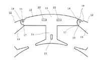
積層鉄心3は、図5に示すように各磁極ティース部14が略平行になるように直線状に展開された状態で電磁鋼板をプレス加工して製造されるものであり、図6に示すように、バックヨーク部13の一端に略凸状部17、他端に略凹状部18、略凸状部17および略凹状部18の外周側に設けられた外周側切り欠き部19を有するコア片16を、図5(A)、図5(B)に示すように所定ピッチで略凸状部17と略凹状部18が対向するように順次配列された第1のコア部材20と、第1のコア部材20とは略凸状部17と略凹状部18の方向が逆向きとなるように所定ピッチで略凸状部17と略凹状部18が対向するように順次配列された第2のコア部材21とが、例えば図3に示すように各々3層毎に積層されて抜きカシメ22によって固定されている。
As shown in FIG. 6, the laminated
なお、回転軸部15はコア片16の略凸状部17に設けられている。ここで、外周側切り欠き部19は、回転軸部15を通り磁極ティース14に平行な直線に対して対称形状をしており、第1のコア部材20と第2のコア部材21とで磁気的なバランスがとれるためにトルク脈動を低減できるとともに、後述する当該積層鉄心のプレス加工工程において、外周側切り欠き部19を形成するパンチを1種類とすることができ、金型の簡素化や小型化を図ることができる。
The rotating
コア片16は、図2、図4に示すように、回転軸部15を中心として回転させて円弧状に積層鉄心3を閉じた時に略凸状部17と略凹状部18が突き合わさるように構成されている。ここで、回転軸部15の軸心P1は図7に示すように略凸状部17の円弧部の中心P2よりも外周側に位置するように設けられているので、図5、図6に示すように各磁極ティース部14が略平行になるように直線状に積層鉄心3を展開した状態において、隣接するコア片16の略凸状部17と略凹状部18間に外周側切り欠き部19から内周側に繋がるコア片間隙間23が形成される。
As shown in FIGS. 2 and 4, the
また、図7の二点鎖線で示すようにコア片16を閉じて円環状の積層鉄心3としたとき、略凹状部18と略凸状部17が付き合わさってバックヨーク部13の磁気抵抗を小さくすることができ、回転電機1の効率のロスを抑制することができる。
Further, when the
続いて、図8の(A)〜(H)を用いて、積層鉄心3を製造するプレス加工工程を説明する。まず、プレスにセットされた帯状の電磁鋼板に対し、工程(A)において、金型との位置決めを行うパイロット穴30を打抜く。続いて、電磁鋼板が等ピッチで材料送り方向へ移動し、各工程の加工を連続的に行なう。
Then, the press work process which manufactures the
工程(B)は、コア片16のバックヨーク部13の隣接する端部間の反磁極ティース部側に位置する第1部位を打ち抜く第1工程であり、第1部位である外周側切り欠き部19を形成するためのスリット31を打ち抜く。
The step (B) is a first step of punching out a first portion located on the side opposite to the magnetic pole teeth between the adjacent end portions of the
工程(C)は、コア片16のバックヨーク部13の隣接する端部間の磁極ティース部側に位置する第2部位を打ち抜く第2工程であり、図は一例として、磁極ティース部14を形成するよう打ち抜く第4工程とが一体的に動作され、第2部位と磁極ティース14を形成するスリット32を打ち抜く。
Step (C) is a second step of punching out a second portion located on the side of the magnetic pole teeth between the adjacent ends of the
工程(D),(E)は、第1工程により打ち抜かれる第1部位と第2工程により打ち抜かれる第2部位とを連通する部位を打ち抜く第3工程であり、コア片16のバックヨーク部13の端部の略凸状部17と略凹状部18を形成するためのコア片間隙間23であるスリット33,34を打ち抜く。
Steps (D) and (E) are a third step of punching out a portion that connects the first portion punched out in the first step and the second portion punched out in the second step, and the
これらスリット33,34を打ち抜くパンチは、図5(A)、図5(B)に示す2種の第1のコア部材20、第2のコア部材21を形成するために、プレスの動作と同期して自動的に切り替えられ、スリット33,34が重複して打ち抜かれることはない。例えば、所定の積層鉄心3の積層枚数、例えば3枚毎にスリット33とスリット34が自動的に切り替えられて打ち抜かれる。
The punches for punching the
ここで、スリット31,32,33,34はそれぞれ独立したパンチで打ち抜くため、各々のパンチの製作が容易であると共に、予めスリット31,32を打抜いた後にスリット33,34を打抜くため、パンチの剛性が比較的小さいスリット33,34のパンチに加わる負荷を軽減できる。
Here, since the
なお、スリット33,34のパンチの耐久性をさらに向上するためには、コア片間隙間23にあたるスリット33,34のパンチの幅をコア片16(電磁鋼板)の板厚以上に設定することが好ましい。
In order to further improve the durability of the punches of the
ここで、前述のように外周側切り欠き部19を形成するスリット31が、回転軸部15を通り磁極ティース14に平行な直線に対して対称形状、つまりスリット33,34に対して対称形状であるため、1種類のパンチで外周側切り欠き部19を形成することができ、工程(B)に集約できることから、金型の簡素化や小型化を図ることができる。
Here, as described above, the
続いて、工程(F)では、抜きカシメ22が嵌りこむスリット35と、回転軸部15が嵌りこむ穴36を打ち抜き、工程(G)では、抜きカシメ22と回転軸部15のダボを成形する。これら工程(F)、工程(G)は選択的に切り替えられて形成される。例えば、工程(F)は所定の積層鉄心3の積層枚数、例えば3枚毎にスリット35と穴36が自動的に切り替えられて打ち抜かれる。このスリット35に抜きカシメ22が嵌りこみ、穴36に回転軸部15が嵌りこむように積層される。
Subsequently, in the step (F), the
また、第1のコア部材20と第2のコア部材21とで磁気的なバランスがとれるためにトルク脈動を低減できる。最後に、工程(H)でコア片16の外周を打ち抜き、連続的に金型内部へコア片16を積層するが、自動切り替えパンチで構成される工程(F)が所定の積層鉄心3の積層枚数に達する時点で有効となることで、複数個の積層鉄心3が抜きカシメによって連結されるのを防止している。
Further, since the
なお、工程(F)、工程(G)は、工程(D)が選択された第1のコア部材20を対象とした場合について述べたが、図示はしないが工程(E)を選択して同様の工程(F)、工程(G)を実施した後、工程(H)でコア片16の外周を打ち抜き、連続的に金型内部へコア片16を積層される。
In addition, although the process (F) and the process (G) described the case where the
この発明の実施の形態における回転電機の積層鉄心は、隣接するコア片16のバックヨーク部13の端部に略凸状部17と略凹状部18を形成する際、バックヨーク部13の隣接する端部間の反磁極ティース部側に位置する第1部位を打ち抜く第1工程と、バックヨーク部13の隣接する端部間の磁極ティース部側に位置する第2部位を打ち抜く第2工程と、第1工程により打ち抜かれる第1部位と第2工程により打ち抜かれる第2部位とを連通する部位を打ち抜く第3工程に分割しているため、パンチの製作が容易となると共に、パンチの耐久性が向上し、コア片16を直線状に配列した状態でのプレス加工の量産性を向上できる。
In the laminated iron core of the rotating electrical machine according to the embodiment of the present invention, when the substantially
また、この実施の形態1で製造した積層鉄心は、加工歪を抑制でき、効率やトルク脈動などの特性向上を図ることができるとともに、材料歩留りを向上することができる。さらに、円弧状や環状の状態でプレス加工した場合に比べて電磁鋼板の磁気異方性の影響を低減でき、トルク脈動を低減することができる。 In addition, the laminated iron core manufactured in the first embodiment can suppress processing strain, improve characteristics such as efficiency and torque pulsation, and improve material yield. Furthermore, the influence of the magnetic anisotropy of the electromagnetic steel sheet can be reduced and torque pulsation can be reduced as compared with the case of pressing in an arcuate or annular state.
また、コア片16のバックヨーク部13の隣接する端部間の磁極ティース部側に位置する第2部位を打ち抜く第2工程と、磁極ティース部14を形成するよう打ち抜く第4工程とが一体的に動作される場合について述べたが、これに限定されるものではなく、第2部位を打ち抜く第2工程と、磁極ティース14を形成する打ち抜き工程とは分離して打ち抜くようにしてもよいことは勿論のことである。さらに、磁極ティース14を形成する打ち抜き工程とコア16片の外周を打ち抜く工程(H)とを一体的に打ち抜くようにしてもよく、工程数を縮小して金型の小型化を図ることもできる。
Also, the second step of punching out the second portion located on the side of the magnetic pole teeth between the adjacent ends of the
ところで、上述した実施の形態においては、バックヨーク部13の隣接する端部間の反磁極ティース部側に位置する第1部位を打ち抜く第1工程と、バックヨーク部13の隣接する端部間の磁極ティース部側に位置する第2部位を打ち抜く第2工程と、第1工程により打ち抜かれる第1部位と第2工程により打ち抜かれる第2部位とを連通する部位を打ち抜く第3工程に分割した場合について述べたが、第1部位を打ち抜く第1工程と、第1部位と第2部位とを連通する部位を打ち抜く第3工程と共通、すなわち、同時に打ち抜くようにしてもよく、上述した従来のものと比し、パンチの製作が容易となると共に、パンチの耐久性が向上し、コア片16を直線状に配列した状態でのプレス加工の量産性を向上できる。
By the way, in embodiment mentioned above, between the 1st process which punches out the 1st site | part located in the antimagnetic teeth part side between the adjacent edge parts of the
また、上述した実施の形態においては、バックヨーク部13の隣接する端部間の反磁極ティース部側に位置する第1部位を打ち抜く第1工程と、バックヨーク部13の隣接する端部間の磁極ティース部側に位置する第2部位を打ち抜く第2工程と、第1工程により打ち抜かれる第1部位と第2工程により打ち抜かれる第2部位とを連通する部位を打ち抜く第3工程に分割した場合について述べたが、第2部位を打ち抜く第2工程と、第1部位と第2部位とを連通する部位を打ち抜く第3工程と共通、すなわち、同時に打ち抜くようにしてもよく、上述した従来のものと比し、パンチの製作が容易となると共に、パンチの耐久性が向上し、コア片16を直線状に配列した状態でのプレス加工の量産性を向上できる。
In the above-described embodiment, the first step of punching out the first portion located on the side of the anti-magnetic teeth portion between the adjacent end portions of the
なお、上記実施の形態では、外周側切り欠き部19を工程(B)にて形成していたが、コア16片の外周を打ち抜く工程(H)に集約して一体的に打ち抜くことで、工程数を縮小して金型の小型化を図ることもできる。
In the embodiment described above, the outer
また、上記実施の形態では、回転軸部15によって隣接するコアブロック12が連結された積層鉄心を製造する方法であるが、この回転軸部15の加工を省略し、コアブロック12が各々分割されている積層鉄心の製造方法にも適用できる。この場合、分割型積層鉄心の材料歩留りを向上するとともに、生産性を向上する効果が得られる。
Moreover, in the said embodiment, although it is a method of manufacturing the laminated iron core with which the
なお、この発明は、その発明の範囲内において、実施の形態を適宜、変形、省略することが可能である。 In the present invention, the embodiments can be appropriately modified and omitted within the scope of the invention.
この発明は、コア片の加工歪みを低減して効率やトルク脈動などの特性向上を図ることができる積層鉄心の製造方法の実現に好適である。 The present invention is suitable for realizing a method for manufacturing a laminated iron core that can reduce processing distortion of the core piece and improve characteristics such as efficiency and torque pulsation.
Claims (2)
前記複数のコア片を直線状に配置して打ち抜くプレス工程と、前記複数のコア片を積層する積層工程とを備え、
前記プレス工程は、前記略凸状部の位置に回転軸部を形成する工程と、前記コア片間隙間を打ち抜く工程と、前記コア片間隙間に隣接する外周側切り欠き部を打ち抜く工程と、前記磁極ティース部を形成する工程とを含み、
前記外周側切り欠き部は、前記回転軸部を通り前記磁極ティース部に平行な直線に対して対称形状をしており、前記コア片間隙間の打ち抜き幅が前記コア片の板厚以上であることを特徴とする積層鉄心の製造方法。 Adjacent ends of the back yoke portions of a plurality of divided core pieces composed of a back yoke portion and a magnetic pole tooth portion protruding from the back yoke portion are provided with a substantially convex portion having an arc on one end side. A substantially concave portion having an arc on the other end side, and the substantially convex portion on one end side of the core piece and the substantially concave portion on the other end side of the core piece provide a gap between the core pieces. sandwiched therebetween are formed so as to mate-out collision, first core formed by sequentially arranging the core pieces having a back yoke portion having the substantially concave portion to the substantially convex portion and the other end side to one end side Forming a member , forming a substantially concave portion at a position corresponding to the position of the substantially convex portion of the core piece of the first core member, and the position of the substantially concave portion of the core piece of the first core member the second core portion formed by sequentially arranging the core pieces having a back yoke part and generally convex portion in a position corresponding to the Forming a said a first core member and the second core member is a method of manufacturing a laminated core formed by caulking laminated punching alternately,
A pressing step of arranging and punching the plurality of core pieces in a straight line; and a lamination step of stacking the plurality of core pieces,
The pressing step includes a step of forming a rotary shaft portion at the position of the substantially convex portion, a step of punching out the gap between the core pieces, and a step of punching out an outer peripheral side notch portion between the core piece gaps, Forming the magnetic pole teeth portion,
The outer peripheral notch has a symmetrical shape with respect to a straight line passing through the rotating shaft and parallel to the magnetic teeth portion, and a punching width between the core piece gaps is equal to or greater than a plate thickness of the core piece. The manufacturing method of the laminated iron core characterized by the above-mentioned.
Priority Applications (1)
| Application Number | Priority Date | Filing Date | Title |
|---|---|---|---|
| JP2015109459A JP6045638B2 (en) | 2015-05-29 | 2015-05-29 | Manufacturing method of laminated iron core |
Applications Claiming Priority (1)
| Application Number | Priority Date | Filing Date | Title |
|---|---|---|---|
| JP2015109459A JP6045638B2 (en) | 2015-05-29 | 2015-05-29 | Manufacturing method of laminated iron core |
Related Parent Applications (1)
| Application Number | Title | Priority Date | Filing Date |
|---|---|---|---|
| JP2013537327A Division JPWO2013051125A1 (en) | 2011-10-06 | 2011-10-06 | Manufacturing method of laminated iron core and laminated iron core produced thereby |
Publications (2)
| Publication Number | Publication Date |
|---|---|
| JP2015149894A JP2015149894A (en) | 2015-08-20 |
| JP6045638B2 true JP6045638B2 (en) | 2016-12-14 |
Family
ID=53892830
Family Applications (1)
| Application Number | Title | Priority Date | Filing Date |
|---|---|---|---|
| JP2015109459A Active JP6045638B2 (en) | 2015-05-29 | 2015-05-29 | Manufacturing method of laminated iron core |
Country Status (1)
| Country | Link |
|---|---|
| JP (1) | JP6045638B2 (en) |
Families Citing this family (2)
| Publication number | Priority date | Publication date | Assignee | Title |
|---|---|---|---|---|
| JP6778497B2 (en) | 2016-03-22 | 2020-11-04 | 株式会社三井ハイテック | Manufacturing method of laminated iron core and its manufacturing equipment |
| WO2020194787A1 (en) * | 2019-03-28 | 2020-10-01 | 三菱電機株式会社 | Manufacturing method for armature core, manufacturing method for electric machine, and electric machine |
Family Cites Families (4)
| Publication number | Priority date | Publication date | Assignee | Title |
|---|---|---|---|---|
| JPH0951640A (en) * | 1995-08-04 | 1997-02-18 | Seiko Epson Corp | Motor yoke structure |
| JP3279279B2 (en) * | 1998-06-30 | 2002-04-30 | 三菱電機株式会社 | Iron core equipment |
| JP5097491B2 (en) * | 2007-09-25 | 2012-12-12 | 日立アプライアンス株式会社 | Washing machine drive motor |
| JP2009077600A (en) * | 2007-09-25 | 2009-04-09 | Hitachi Appliances Inc | Washing machine drive motor |
-
2015
- 2015-05-29 JP JP2015109459A patent/JP6045638B2/en active Active
Also Published As
| Publication number | Publication date |
|---|---|
| JP2015149894A (en) | 2015-08-20 |
Similar Documents
| Publication | Publication Date | Title |
|---|---|---|
| WO2013051125A1 (en) | Laminated core manufacturing method and laminated core manufactured using same | |
| JP5579832B2 (en) | Rotating electrical machine laminated iron core | |
| JP5511956B2 (en) | Rotating electrical machine laminated iron core | |
| TWI454018B (en) | Laminated iron core of linear motor and method of making same | |
| JP5603437B2 (en) | Laminated iron core for rotating electrical machine and method for manufacturing the same | |
| JP5719979B1 (en) | Laminated iron core manufacturing apparatus and laminated iron core manufacturing method | |
| WO2012057100A1 (en) | Divided iron core and manufacturing method therefor | |
| JP5638475B2 (en) | Laminated iron core of linear motor and method of manufacturing the same | |
| JP2011030320A (en) | Dynamo-electric machine and method of manufacturing the same | |
| JP2010178487A (en) | Manufacturing method for laminated core and forward metal mold device | |
| JP6045638B2 (en) | Manufacturing method of laminated iron core | |
| JP2017208986A (en) | Manufacturing method of laminated iron core for rotating electrical machine | |
| JP5528164B2 (en) | Stator for rotating electrical machine and method for manufacturing the same | |
| JP6630123B2 (en) | Laminated core and method of manufacturing the same | |
| JP4794650B2 (en) | Rotating electric machine | |
| JP4150397B2 (en) | Laminated iron core and method for manufacturing the same | |
| TWI584558B (en) | Rotary motor stator core and stator, and rotary motor | |
| JPWO2013051125A1 (en) | Manufacturing method of laminated iron core and laminated iron core produced thereby | |
| JP2017175774A (en) | Rotary electric machine and method of manufacturing divided stator steel plate | |
| JP2007049807A (en) | Permanent magnet type motor | |
| JP4021433B2 (en) | Stator of adder motor | |
| WO2022137621A1 (en) | Split core, dynamo-electric machine, method for manufacturing split core, and method for manufacturing dynamo-electric machine | |
| JP2005095000A (en) | Stator of inner rotary type dynamo-electric motor |
Legal Events
| Date | Code | Title | Description |
|---|---|---|---|
| A621 | Written request for application examination |
Free format text: JAPANESE INTERMEDIATE CODE: A621 Effective date: 20150529 |
|
| A131 | Notification of reasons for refusal |
Free format text: JAPANESE INTERMEDIATE CODE: A131 Effective date: 20160308 |
|
| A601 | Written request for extension of time |
Free format text: JAPANESE INTERMEDIATE CODE: A601 Effective date: 20160427 |
|
| A521 | Request for written amendment filed |
Free format text: JAPANESE INTERMEDIATE CODE: A523 Effective date: 20160627 |
|
| TRDD | Decision of grant or rejection written | ||
| A01 | Written decision to grant a patent or to grant a registration (utility model) |
Free format text: JAPANESE INTERMEDIATE CODE: A01 Effective date: 20161018 |
|
| A61 | First payment of annual fees (during grant procedure) |
Free format text: JAPANESE INTERMEDIATE CODE: A61 Effective date: 20161115 |
|
| R151 | Written notification of patent or utility model registration |
Ref document number: 6045638 Country of ref document: JP Free format text: JAPANESE INTERMEDIATE CODE: R151 |
|
| R250 | Receipt of annual fees |
Free format text: JAPANESE INTERMEDIATE CODE: R250 |
|
| R250 | Receipt of annual fees |
Free format text: JAPANESE INTERMEDIATE CODE: R250 |
|
| R250 | Receipt of annual fees |
Free format text: JAPANESE INTERMEDIATE CODE: R250 |
|
| R250 | Receipt of annual fees |
Free format text: JAPANESE INTERMEDIATE CODE: R250 |
|
| R250 | Receipt of annual fees |
Free format text: JAPANESE INTERMEDIATE CODE: R250 |
|
| R250 | Receipt of annual fees |
Free format text: JAPANESE INTERMEDIATE CODE: R250 |