JP6045171B2 - Ophthalmic system - Google Patents
Ophthalmic system Download PDFInfo
- Publication number
- JP6045171B2 JP6045171B2 JP2012082689A JP2012082689A JP6045171B2 JP 6045171 B2 JP6045171 B2 JP 6045171B2 JP 2012082689 A JP2012082689 A JP 2012082689A JP 2012082689 A JP2012082689 A JP 2012082689A JP 6045171 B2 JP6045171 B2 JP 6045171B2
- Authority
- JP
- Japan
- Prior art keywords
- tomographic image
- image
- display
- light
- eye
- Prior art date
- Legal status (The legal status is an assumption and is not a legal conclusion. Google has not performed a legal analysis and makes no representation as to the accuracy of the status listed.)
- Expired - Fee Related
Links
- 230000003287 optical effect Effects 0.000 claims description 63
- 238000003384 imaging method Methods 0.000 claims description 62
- 238000005286 illumination Methods 0.000 claims description 8
- 230000002093 peripheral effect Effects 0.000 claims 1
- 238000010408 sweeping Methods 0.000 claims 1
- 210000000695 crystalline len Anatomy 0.000 description 43
- 238000005259 measurement Methods 0.000 description 37
- 239000000835 fiber Substances 0.000 description 32
- 238000012545 processing Methods 0.000 description 30
- 238000012014 optical coherence tomography Methods 0.000 description 29
- 208000010412 Glaucoma Diseases 0.000 description 7
- 206010025421 Macule Diseases 0.000 description 7
- 238000003745 diagnosis Methods 0.000 description 7
- 201000002862 Angle-Closure Glaucoma Diseases 0.000 description 5
- 230000006870 function Effects 0.000 description 5
- 230000010287 polarization Effects 0.000 description 5
- 230000002207 retinal effect Effects 0.000 description 5
- 238000004458 analytical method Methods 0.000 description 4
- 238000003325 tomography Methods 0.000 description 4
- 238000010586 diagram Methods 0.000 description 3
- 229910052736 halogen Inorganic materials 0.000 description 3
- 150000002367 halogens Chemical class 0.000 description 3
- 230000004410 intraocular pressure Effects 0.000 description 3
- 238000000034 method Methods 0.000 description 3
- 238000012986 modification Methods 0.000 description 3
- 230000004048 modification Effects 0.000 description 3
- 230000035945 sensitivity Effects 0.000 description 3
- 210000001519 tissue Anatomy 0.000 description 3
- 208000006550 Mydriasis Diseases 0.000 description 2
- 230000008859 change Effects 0.000 description 2
- 230000000694 effects Effects 0.000 description 2
- 210000004220 fundus oculi Anatomy 0.000 description 2
- 239000013307 optical fiber Substances 0.000 description 2
- 230000008569 process Effects 0.000 description 2
- 210000001747 pupil Anatomy 0.000 description 2
- 230000009467 reduction Effects 0.000 description 2
- 230000011514 reflex Effects 0.000 description 2
- 208000024891 symptom Diseases 0.000 description 2
- 238000012935 Averaging Methods 0.000 description 1
- 230000002159 abnormal effect Effects 0.000 description 1
- 210000001742 aqueous humor Anatomy 0.000 description 1
- 230000004323 axial length Effects 0.000 description 1
- 210000004087 cornea Anatomy 0.000 description 1
- 201000010099 disease Diseases 0.000 description 1
- 208000037265 diseases, disorders, signs and symptoms Diseases 0.000 description 1
- 239000006185 dispersion Substances 0.000 description 1
- 210000001061 forehead Anatomy 0.000 description 1
- 239000011521 glass Substances 0.000 description 1
- 238000010191 image analysis Methods 0.000 description 1
- 238000003709 image segmentation Methods 0.000 description 1
- 239000004973 liquid crystal related substance Substances 0.000 description 1
- 239000011159 matrix material Substances 0.000 description 1
- 210000001328 optic nerve Anatomy 0.000 description 1
- 230000001151 other effect Effects 0.000 description 1
- 230000001681 protective effect Effects 0.000 description 1
- 210000001525 retina Anatomy 0.000 description 1
- 239000000790 retinal pigment Substances 0.000 description 1
- 230000011218 segmentation Effects 0.000 description 1
- 239000004065 semiconductor Substances 0.000 description 1
- 229910052709 silver Inorganic materials 0.000 description 1
- 239000004332 silver Substances 0.000 description 1
- 239000007787 solid Substances 0.000 description 1
- 230000003595 spectral effect Effects 0.000 description 1
- 210000001835 viscera Anatomy 0.000 description 1
- 238000012800 visualization Methods 0.000 description 1
Images


Classifications
-
- A—HUMAN NECESSITIES
- A61—MEDICAL OR VETERINARY SCIENCE; HYGIENE
- A61B—DIAGNOSIS; SURGERY; IDENTIFICATION
- A61B3/00—Apparatus for testing the eyes; Instruments for examining the eyes
- A61B3/10—Objective types, i.e. instruments for examining the eyes independent of the patients' perceptions or reactions
- A61B3/14—Arrangements specially adapted for eye photography
-
- A—HUMAN NECESSITIES
- A61—MEDICAL OR VETERINARY SCIENCE; HYGIENE
- A61B—DIAGNOSIS; SURGERY; IDENTIFICATION
- A61B3/00—Apparatus for testing the eyes; Instruments for examining the eyes
- A61B3/10—Objective types, i.e. instruments for examining the eyes independent of the patients' perceptions or reactions
- A61B3/102—Objective types, i.e. instruments for examining the eyes independent of the patients' perceptions or reactions for optical coherence tomography [OCT]
Landscapes
- Health & Medical Sciences (AREA)
- Life Sciences & Earth Sciences (AREA)
- Medical Informatics (AREA)
- Biophysics (AREA)
- Ophthalmology & Optometry (AREA)
- Engineering & Computer Science (AREA)
- Biomedical Technology (AREA)
- Heart & Thoracic Surgery (AREA)
- Physics & Mathematics (AREA)
- Molecular Biology (AREA)
- Surgery (AREA)
- Animal Behavior & Ethology (AREA)
- General Health & Medical Sciences (AREA)
- Public Health (AREA)
- Veterinary Medicine (AREA)
- Nuclear Medicine, Radiotherapy & Molecular Imaging (AREA)
- Radiology & Medical Imaging (AREA)
- Eye Examination Apparatus (AREA)
Description
本発明は、眼科装置に関する。 The present invention relates to an ophthalmic apparatus.
光干渉断層計(OCT;Optical Coherence Tomography)などの眼部の断層画像撮像装置は、網膜層内部の状態を三次元的に観察することが可能である。この断層画像撮像装置は、疾病の診断をより的確に行うのに有用であることから近年注目を集めている。具体的には、断層画像は緑内障の診断に用いられることが知られている(特許文献1)。 An ocular tomographic imaging apparatus such as an optical coherence tomography (OCT) can observe the state inside the retinal layer three-dimensionally. This tomographic imaging apparatus has attracted attention in recent years because it is useful for more accurately diagnosing diseases. Specifically, it is known that tomographic images are used for diagnosis of glaucoma (Patent Document 1).
緑内障には急性緑内障発作と呼ばれる症状がある。急性緑内障発作は隅角の狭い患者が、散瞳により虹彩根部が太くなり隅角にある房水の出口である繊維柱体を塞ぐことで起こる。具体的には繊維柱体が虹彩により塞がれると眼圧が高くなり、水晶体が角膜側に押される。そして水晶体により虹彩が圧迫され更に繊維柱体が塞がれることで眼圧が急激に高くなり、視神経が損傷する。 Glaucoma has a symptom called an acute glaucoma attack. An acute glaucoma attack occurs when a patient with a narrow angle narrows the root of the iris due to a mydriasis and closes the fiber column that is the outlet of aqueous humor at the corner. Specifically, when the fiber column is blocked by the iris, the intraocular pressure increases and the lens is pushed toward the cornea. Then, the iris is pressed by the crystalline lens, and the fiber column is further blocked, so that the intraocular pressure increases rapidly and the optic nerve is damaged.
暗所では散瞳し虹彩が縮み虹彩根部が太くなるため、繊維柱体が虹彩に接触しやすく、明所に比べて急性緑内障発作が起こりやすくなる。一方、明所では、急性緑内障発作は暗所に比べ起こりにくくなる。このように、急性緑内障発作の起こりやすさは周辺の照明環境に依存する。すなわち、被検眼から得られる画像または測定値等の固有情報は照明環境に依存する場合がある。 In the dark place, mydriasis, the iris shrinks, and the iris root becomes thicker, so the fiber column is more likely to come into contact with the iris, and acute glaucoma attacks are more likely to occur than in the light place. On the other hand, acute glaucoma attacks are less likely in the light than in the dark. Thus, the likelihood of an acute glaucoma attack depends on the surrounding lighting environment. That is, unique information such as images or measurement values obtained from the eye to be examined may depend on the illumination environment.
しかしながら、被検眼の固有情報には固有情報取得時の照明環境は関連付けられておらず、検査者は正確に診断を行うことが困難であった。
本発明は、より正確な診断を可能とすることを目的の一つとする。
なお、前記目的に限らず、後述する発明を実施するための形態に示す各構成により導かれる作用効果であって、従来の技術によっては得られない作用効果を奏することも本発明の他の目的の一つとすることができる。
However, the lighting environment at the time of acquiring the specific information is not associated with the specific information of the eye to be inspected, and it is difficult for the examiner to accurately diagnose.
An object of the present invention is to enable more accurate diagnosis.
In addition, the present invention is not limited to the above-described object, and other effects of the present invention can be achieved by the functions and effects derived from the respective configurations shown in the embodiments for carrying out the invention which will be described later. It can be one of.
本発明の眼科装置は、被検眼の固有情報を取得する眼科装置と、前記眼科装置周辺の明るさを示す値を取得する取得手段と、前記取得手段で取得した明るさを示す値と前記断層画像と関連付けて記憶手段に記録する記録手段と、を備える。 An ophthalmologic apparatus according to the present invention includes an ophthalmologic apparatus that acquires specific information of an eye to be examined, an acquisition unit that acquires a value indicating brightness around the ophthalmologic apparatus, a value indicating the brightness acquired by the acquisition unit, and the tomography Recording means for recording in the storage means in association with the image.
本発明によれば、正確な診断を可能とすることができる。 According to the present invention, an accurate diagnosis can be made.
本発明に係る装置は、被検眼、皮膚、内臓等の被検体に適用することができる。また、本発明に係る装置としては、例えば、眼科装置や内視鏡等である。以下、本発明の一例として、本実施形態に係る眼科装置について、図面を用いて詳細に説明する。 The apparatus according to the present invention can be applied to a subject such as an eye to be examined, skin, and internal organs. Moreover, examples of the apparatus according to the present invention include an ophthalmologic apparatus and an endoscope. Hereinafter, as an example of the present invention, an ophthalmologic apparatus according to the present embodiment will be described in detail with reference to the drawings.
(第1の実施形態)
[装置の全体構成]
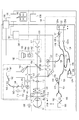
図1は、本実施形態における眼科装置の構成の一例を示す概略図である。
(First embodiment)
[Overall configuration of the device]
FIG. 1 is a schematic diagram illustrating an example of the configuration of an ophthalmologic apparatus according to the present embodiment.
本装置は、SS−OCT(Swept Source OCT;以下、単にOCTという場合がある)100、走査型検眼鏡(Scanning Laser Ophthalmoscope:以下、SLOという場合がある)140、前眼部撮像部160、内部固視灯170、制御部200から構成される。すなわち、図1に示す眼科装置は被検眼の固有情報を取得する。また、本眼科装置は照度計500を備えている。照度計500は断層画像の取得が行われる検査室の明るさを示す値(例えば照度)を計測する。すなわち、照度計500は眼科装置周辺の明るさを示す値を計測する。なお、照度計500は、眼科装置と一体に構成されていてもよいし、眼科装置とは別体に備えられていてもよい。
The apparatus includes an SS-OCT (Swept Source OCT; hereinafter simply referred to as OCT) 100, a scanning ophthalmoscope (hereinafter also referred to as SLO) 140, an anterior
内部固視灯170を点灯して被検眼に注視させた状態で、前眼部撮像部160により観察される被検眼の前眼部の画像を用いて、装置のアライメントが行われる。アライメント完了後に、OCT100とSLO140による眼底の撮像が行われる。なお、OCT100、SLO140は眼底の撮像に限定されるものではなく、前眼部の撮像を行うことも可能である。
The apparatus is aligned using an image of the anterior eye portion of the eye to be examined observed by the anterior
<OCT100の構成>
OCT100の構成の一例について説明する。
<Configuration of OCT100>
An example of the configuration of the OCT 100 will be described.
OCT100は被検眼の断層画像を取得する断層画像取得手段の一例に相当する。
光源101は、可変波長光源であり、例えば、中心波長1040nm、バンド幅100nmの光を出射する。光源101から出射される光の波長は制御部191によって制御される。より具体的には、断層画像を取得する際に、制御部191によって光源101から出射される光の波長は掃引される。すなわち、制御部191は光源から出射される光の波長を掃引させる制御手段の一例に相当する。光源101から出射された光は、ファイバ102、偏光コントローラ103を介して、ファイバカップラ104に導かれ、光量を測定するファイバ130とOCT測定するファイバ105に分岐される。光源101から出射された光は、ファイバ130を介し、PM(Power Meter)131にてパワーが測定される。ファイバ105を介した光は、第二のファイバカップラ106に導かれる。ファイバカップラ106において、光は、測定光(OCT測定光とも言う)と参照光に分岐される。
The OCT 100 corresponds to an example of a tomographic image acquisition unit that acquires a tomographic image of the eye to be examined.
The
偏光コントローラ103は、光源101から出射された光の偏光の状態を調整するものであり、直線偏光に調整される。ファイバカップラ104の分岐比は、99:1であり、ファイバカップラ106の分岐比は、90(参照光):10(測定光)である。なお、分岐比はこれらの値に限定されるものではなく、他の値とすることも可能である。
The
ファイバカップラ106で分岐された測定光は、ファイバ118を介してコリメータ117から平行光として出射される。出射された測定光は、眼底Erにおいて測定光を水平方向(紙面上下方向)にスキャンするガルバノミラーから構成されるXスキャナ107、レンズ108を介してレンズ109に到達する。さらに、レンズ109からの測定光は眼底Erにおいて測定光を垂直方向(紙面奥行き方向)にスキャンするガルバノミラーから構成されるYスキャナ110を介し、ダイクロイックミラー111に到達する。ここで、Xスキャナ107、Yスキャナ110は、駆動制御部180により制御され、眼底Erで所望の範囲の領域を測定光により走査することができる。ダイクロイックミラー111は、例えば950nm〜1100nmの光を反射し、それ以外の光を透過する特性を有する。
ダイクロイックミラー111により反射された測定光は、レンズ112を介し、ステージ116上に乗ったフォーカスレンズ114に到達する。フォーカスレンズ114で測定光は、被検体である眼の前眼部Eaを介し、眼底Erの網膜層にフォーカスされる。すなわち、光源101から被検眼までの光学系は光源からの光を被検眼に導く照明光学系の一例に相当する。眼底Erを照射した測定光は各網膜層で反射・散乱し、上述の光学経路を介してファイバカップラ106に戻る。眼底Erからの測定光はファイバカップラ106からファイバ125を介し、ファイバカップラ126に到達する。
The measurement light branched by the
The measurement light reflected by the
なお、フォーカスレンズ114の光軸方向への移動は駆動制御部180により制御される。また、本実施形態ではフォーカスレンズ114はOCT100とSLO140と共通に用いられているが、これに限定されるものではなく、それぞれの光学系に別々にフォーカスレンズを備えることとしてもよい。また、フォーカスレンズの駆動制御部180による制御は光源101が用いる波長と光源141が用いる波長との違いに基づいてフォーカスレンズを駆動することとしてもよい。例えば、OCT100とSLO140とに共通でフォーカスレンズが設けられている場合、駆動制御部180はSLO140による撮影とOCT100による撮影とが切り替えられると、波長の違いに応じてフォーカスレンズ114を移動させる。また、フォーカスレンズがOCT100およびSLO140のそれぞれの光学系に設けられている場合、一方の光学系のフォーカスレンズが調整されると駆動制御部180は波長の違いに応じて他方の光学系のフォーカスレンズを移動させる。
The movement of the
また、前眼部の断層撮影を行う撮影モードの場合、フォーカス位置を眼底ではなく前眼部の所定の部位に合わせる。この前眼部へのフォーカス調整は、フォーカスレンズ114の位置を移動させることにより行っても良いが、あるいは専用のレンズ等の光学部材をフォーカスレンズ114の前後の光路に挿入することでフォーカス位置を調整することができる。この場合、光学部材は駆動部により光路に対して挿脱可能である。駆動制御部180は前眼部撮影モードが選択された場合には光学部材を光路に挿入し、眼底撮影モードが選択された場合には光学部材を光路中から退避させる。
In the case of an imaging mode in which tomographic imaging of the anterior segment is performed, the focus position is adjusted to a predetermined part of the anterior segment rather than the fundus. The focus adjustment to the anterior segment may be performed by moving the position of the
一方、ファイバカップラ106で分岐された参照光は、ファイバ119を介してコリメータ120−aから平行光として出射される。出射された参照光は分散補償ガラス121を介し、コヒーレンス−ゲートステージ122上のミラー123−a、123−bで反射され、コリメータ120−b、ファイバ124を介し、ファイバカップラ126に到達する。コヒーレンスゲートステージ122は、被検眼の眼軸長の相違等に対応する為、駆動制御部180で制御される。
On the other hand, the reference light branched by the
ファイバカップラ126に到達した測定光と参照光とは合波されて干渉光となり、ファイバ127、128を経由し、光検出器である差動検出器(balanced receiver)129によって干渉信号が電気信号に変換される。変換された電気信号は信号処理部190で解析される。すなわち、被検眼から差動検出器129までの光学系は制御手段により掃引された光の被検眼からの戻り光を撮像手段に導く撮像光学系の一例に相当する。なお、光検出器は差動検出器に限定されるものではなく、他の検出器を用いることとしてもよい。
また、ファイバカップラ126において測定光と参照光とが干渉する構成となっているが、これに限定されるものではない。例えば、ミラー123−aを参照光をファイバ119へ反射するように配置し、ファイバカップラ106において測定光と参照光とを干渉させることとしてもよい。この場合ミラー123−b、コリメータ120−b、ファイバ124およびファイバカップラ126は不要となる。この場合サーキュレータを設けることが好ましい。
The measurement light and the reference light that have reached the
In addition, although the measurement light and the reference light interfere with each other in the
<SLO140の構成>
SLO140の構成の一例について説明する。
<Configuration of SLO140>
An example of the configuration of the
SLO140は被検眼の眼底画像を取得する眼底画像取得手段の一例に相当する。また、SLO140は被検眼の前眼画像を取得する前眼画像取得手段の一例に相当する。
光源141は、例えば半導体レーザであり、本実施形態では、例えば、中心波長780nmの光を出射する。光源141から出射された測定光(SLO測定光とも言う)は、ファイバ142を介し、偏光コントローラ145で直線偏光に調整され、コリメータ143から平行光として出射される。出射された測定光は穴あきミラー144の穴あき部を通過し、レンズ155を介し、眼底Erにおいて測定光を水平方向にスキャンするガルバノミラーから構成されるXスキャナ146、レンズ147、148、眼底Erにおいて測定光を垂直方向にスキャンするガルバノミラーから構成されるYスキャナ149を介し、ダイクロイックミラー154に到達する。なお、偏光コントローラ145を設けないこととしてもよい。Xスキャナ146、Yスキャナ149は駆動制御部180により制御され、眼底上で所望の範囲を測定光で走査できる。ダイクロイックミラー154は、例えば760nm〜800nmを反射し、それ以外の光を透過する特性を有する。
The
The
ダイクロイックミラー154にて反射された直線偏光の測定光は、ダイクロイックミラー111を透過後、OCT100のOCT測定光と同様の光路を経由し、眼底Erに到達する。
The linearly polarized measurement light reflected by the
眼底Erを照射したSLO測定光は、眼底Erで反射・散乱され、上述の光学経路をたどり穴あきミラー144に達する。穴あきミラー144で反射された光が、レンズ150を介し、アバランシェフォトダイオード(以下、APDともいう)152で受光され、電気信号に変換されて、信号処理部190で受ける。
ここで、穴あきミラー144の位置は、被検眼の瞳孔位置と共役となっており、眼底Erに照射された測定光が反射・散乱された光のうち、瞳孔周辺部を通った光が、穴あきミラー144によって反射される。
The SLO measurement light that irradiates the fundus Er is reflected and scattered by the fundus Er and reaches the
Here, the position of the
<前眼部撮像部160>
前眼部撮像部160の構成の一例について説明する。
前眼部撮像部160は、レンズ162、163、164および前眼部カメラ165を備える。
<Anterior
An example of the configuration of the anterior
The anterior
例えば波長850nmの照明光を発するLED115−a、115−bから成る照明光源115は前眼部Eaを照射する。前眼部Eaで反射され光は、フォーカスレンズ114、レンズ112、ダイクロイックミラー111、154を介し、ダイクロイックミラー161に達する。ダイクロイックミラー161は、例えば820nm〜900nmの光を反射し、それ以外の光を透過する特性を有する。ダイクロイックミラー161で反射された光は、レンズ162、163、164を介し、前眼部カメラ165で受光される。前眼部カメラ165で受光された光は、電気信号に変換され、信号処理部190で受ける。
For example, an
<内部固視灯170>
内部固視灯170について説明する。
<
The
内部固視灯170は、表示部171、レンズ172で構成される。表示部171としては例えば複数の発光ダイオード(LD)がマトリックス状に配置されたものを用いる。発光ダイオードの点灯位置は、駆動制御部180の制御により撮像したい部位に合わせて変更される。表示部171からの光は、レンズ172を介し、被検眼に導かれる。表示部171から出射される光は例えば520nmで、駆動制御部180により所望のパターンが表示される。
The
<制御部200>
制御部200について説明する。
制御部200は、駆動制御部180、信号処理部190、制御部191、表示部192から構成される。
<
The
The
駆動制御部180は、上述の通り各部を制御する。
The
信号処理部190は、差動検出器129、APD152、前眼部カメラ165からそれぞれ出力される信号に基づき、画像の生成、生成された画像の解析、解析結果の可視化情報の生成を行う。なお、画像の生成などの詳細については、後述する。
制御部191は、本装置全体を制御すると共に、信号処理部190で生成された画像等を表示部192の表示画面に表示する。表示部192は表示手段または表示装置の一例に相当する。なお、信号処理部190で生成された画像データは、制御部191に有線で送信されても良いし、無線で送信されても良い。また、制御部191は断層画像の撮影開始時の照度計500の測定値を取得し、信号処理部190で生成された前眼部Eaの断層画像と照度計500の測定値とを関連付けて記憶部600に保存する。すなわち、制御部191は眼科装置周辺の明るさを示す値を取得する取得手段の一例に相当する。さらに制御部191は取得手段で取得した明るさを示す値と断層画像と関連付けて記憶手段に記録する記録手段の一例に相当する。
The
The control unit 191 controls the entire apparatus and displays the image generated by the
なお、制御部191が照度計500の測定値を取得するタイミングは断層画像の撮影開始時に限定されるものではなく、撮影終了時や撮影前など他のタイミングであってもよい。また、制御部191によって前眼部Eaの断層画像と関連づけられる照度は照度計500の値に限定されるものではない。例えば、検査者が眼科装置が置かれた検査室の照度を判断し眼科装置にキーボード等の入力手段を用いて入力してもよい。入力する値は具体的な照度の値に限定されるものではなく、明るさを段階的に示す「明るい」、「通常」、「暗い」等の指標であってもよい。制御部191はキーボード等の入力手段を介して入力された情報を断層画像と関連付ける。なお、明るさを段階的に示す指標は3段階に限定されるものではなく、4段階以上であってもよいし2段階であってもよい。
Note that the timing at which the control unit 191 acquires the measurement value of the
また、検査室の明かりを暗くしてから断層画像を取得する場合、虹彩の動きが安定するまで時間を要する(例えば、2〜3分)。従って、虹彩の動きが安定した状態か否かを検査者が撮影後に判断できるように、検査室の明かりを暗くしてから断層画像を撮影するまでの時間を取得し、断層画像と更に関連付け記憶部600に保存することとしてもよい。なお、この時間は検査者がタイマ等により計測して、キーボード等の入力手段を介して眼科装置に入力することとしてもよい。入力手段を介して入力された情報は制御部191によって取得される。また、照度計500の出力を用いて制御部191が所定の照度以下となった時から断層画像の撮影が行われるまでの時間を計時してもよい。すなわち、制御部191は眼科装置周辺の明るさを示す値が所定値以下となってから固有情報を取得するまでの時間を取得する取得手段の一例に相当する。また、制御部191は固有情報記取得手段により取得された眼科装置周辺の明るさを示す値が所定値以下となってから固有情報を取得するまでの時間を関連付けて記憶手段に記録する記録手段の一例に相当する。
Moreover, when acquiring a tomographic image after darkening the light in the examination room, it takes time until the movement of the iris is stabilized (for example, 2 to 3 minutes). Therefore, the time until the tomographic image is taken after the light in the laboratory is darkened is acquired and stored in association with the tomographic image so that the examiner can determine whether or not the movement of the iris is stable after the photographing. It may be stored in the
なお、記憶部600は例えばHDD(Hard Disk Drive)やSSD(Solid State Drive)であり、制御部200内に備えられることとしてもよいし、制御部200の外部に備えられることとしてもよい。すなわち、眼科装置に対して記憶部600は内蔵されていてもよいし外付けであってもよい。また、制御部191と記憶部600とは無線または有線によって接続される。さらに、制御部191と照度計500とは無線または有線によって接続される。
The
表示部192は、例えば、液晶等のディスプレイである。表示部192は、制御部191の制御の下、後述するように種々の情報を表示する。なお、制御部191からの画像データは、表示部192に有線で送信されても良いし、無線で送信されても良い。また、表示部192等は、制御部200に含まれているが、本発明はこれに限らず、制御部200とは別に設けられても良い。
The
また、制御部191と表示部192とを一体的に構成した、ユーザが持ち運び可能な装置の一例であるタブレットでも良い。この場合、表示部192にタッチパネル機能を搭載させ、タッチパネル上で画像の表示位置の移動、拡大縮小、表示される画像の変更等の操作可能に構成することが好ましい。なお、制御部191と表示部192とが一体的に構成された場合でなくとも表示部192にタッチパネル機能を搭載させてもよい。すなわち、指示装置としてタッチパネルを用いることとしてもよい。
Moreover, the tablet which is an example of the apparatus which the control part 191 and the
[画像処理]
次に、信号処理部190における画像生成、画像解析について説明する。
[Image processing]
Next, image generation and image analysis in the
<断層画像生成、及び、眼底画像生成>
信号処理部190は、差動検出器129から出力された干渉信号に対して、一般的な再構成処理を行うことで、断層画像を生成する。
<Tomographic image generation and fundus image generation>
The
まず、信号処理部190は、干渉信号から固定パターンノイズ除去を行う。固定パターンノイズ除去は例えば検出した複数のAスキャン信号を平均することで固定パターンノイズを抽出し、これを入力した干渉信号から減算することで行われる。
First, the
次に、信号処理部190は、有限区間でフーリエ変換した場合にトレードオフの関係となる、深さ分解能とダイナミックレンジとを最適化するために、所望の窓関数処理を行う。 次に、FFT処理を行う事によって、断層画像を生成する。
Next, the
図2に、OCT100で撮像され、信号処理部190で生成された断層画像の一例を示す。
FIG. 2 shows an example of a tomographic image captured by the
図2(A)は正常眼の断層画像の一例であり、図2(B)は近視眼の断層画像の一例であり、網膜色素上皮―脈絡膜境界201と脈絡膜―強膜境界202他の各層境界が撮像されている。図に示すように、OCT100によれば、SD−OCT(Spectral domain OCT)に比べて広い範囲(図の横方向の大きさが大きいとの意味)での断層画像の撮像が可能となる。これは以下の理由によるものである。SD−OCTの分光器では、回折格子による干渉光の損失がある。一方、SS−OCTでは、分光器を用いず干渉光を例えば差動検出する構成とすることで感度向上が容易である。よって、SS−OCTは、SD−OCTと同等の感度で高速化が可能となり、この高速性を活かして、広画角の断層画像を取得することが可能となる。
2A is an example of a normal eye tomographic image, and FIG. 2B is an example of a myopic eye tomographic image in which the retinal pigment epithelium-
またOCT100によれば、SD−OCTに比べて深さ方向に深い(図の縦方向の大きさが大きいとの意味)断層画像の撮像が可能である。これは以下の理由によるものである。SD−OCTで用いられる分光器は、回折格子によって干渉光を空間で分光するため、ラインセンサの隣接する画素間で干渉光のクロストークが発生し易くなる。深さ位置Z=Z0に位置する反射面からの干渉光は、波数kに対してZ0/πの周波数で振動するため、Z0が大きくなる(すなわちコヒーレンスゲート位置から遠く離れる)に従って、干渉光の振動周波数は高くなり、ラインセンサの隣接する画素間での干渉光のクロストークの影響が大きくなる。これによって、SD−OCTでは、より深い位置を撮像しようとすると、感度低下が顕著となる。一方、分光器を用いないSS−OCTは、SD−OCTよりも、深い位置での断層画像の撮像が有利となる。なお、断層画像を表示部192の表示領域に表示する場合、断層自体の画像が無い領域を表示しても意味が無い。そこで、本実施形態では、制御部191は、信号処理部190内のメモリに展開されたデータから断層自体の画像の部分を認識し、表示領域の大きさに合う断層画像を切り出して表示するようにしている。なお、断層自体の画像とは被検眼の眼底組織の画像を指す。
Further, according to the
<セグメンテーション>
信号処理部190は、前述した輝度画像を用いて断層画像のセグメンテーションを行う。
まず、信号処理部190は、処理の対象とする断層画像に対して、メディアンフィルタとSobelフィルタをそれぞれ適用して画像を作成する(以下、それぞれメディアン画像、Sobel画像ともいう)。次に、作成したメディアン画像とSobel画像から、Aスキャン毎にプロファイルを作成する。メディアン画像では輝度値のプロファイル、Sobel画像では勾配のプロファイルとなる。そして、Sobel画像から作成したプロファイル内のピークを検出する。検出したピークの前後やピーク間に対応するメディアン画像のプロファイルを参照することで、網膜層の各領域の境界を抽出する。
<Segmentation>
The
First, the
更に、Aスキャンラインの方向に各層厚をそれぞれ計測し、各層の層厚マップを作成する。 Further, each layer thickness is measured in the direction of the A scan line, and a layer thickness map of each layer is created.
[処理動作]
次に本眼科装置による処理動作の一例について説明する。
[Processing operation]
Next, an example of processing operation by the ophthalmologic apparatus will be described.
図3は、本眼科装置の処理動作の一例を示すフローチャートである。 FIG. 3 is a flowchart showing an example of the processing operation of the ophthalmologic apparatus.
<調整>
まず、ステップS101において、被検眼を本装置に配置した状態で、本装置と被検眼とのアライメントを行う。アライメントの説明に関して、本実施形態に特有な処理について説明し、ワーキングディスタンス、フォーカス、コヒーレンスゲートの調整等は一般的であるのでその説明は省略する。
<Adjustment>
First, in step S101, the apparatus and the eye to be examined are aligned with the eye to be examined being placed on the apparatus. Regarding the description of the alignment, processing unique to the present embodiment will be described, and adjustment of the working distance, focus, coherence gate, and the like are common, and the description thereof will be omitted.
(OCT撮像位置の調整)
図4、図5は、調整時または撮影後に表示部192に表示されるウィンドウ400の一例を示している。
(Adjustment of OCT imaging position)
4 and 5 show an example of a
まず、操作者がマウス等の指示装置(不図示)を用いてカーソルで、領域412又は領域413を指示することにより撮像モードとして、2D撮像モード(図4参照)又は3D撮像モード(図5参照)を指示する。
First, an operator designates the
指示に基づき撮像モードが設定され、設定された撮像モードが領域410に表示され、SLO140で撮像されて信号処理部190で生成された眼底画像(輝度画像)411が表示される。ここで、眼底画像411の外枠で規定される領域は眼底画像の表示領域である。以下、領域410内の眼底画像の表示領域を眼底画像表示領域という場合がある。ここで、眼底画像表示領域は第1の領域の一例に相当する。なお、眼底画像411は調整時の動画像または撮影後の画像である。
The imaging mode is set based on the instruction, the set imaging mode is displayed in the
撮像モードに応じて、眼底画像411上に、OCT100の撮像範囲を示す直線415又は矩形416が重畳表示される。ここで、眼底画像411に表示される撮像範囲を示す表示は直線や矩形に限定されるものではない。例えば、サークルスキャンが行われる場合には円が眼底画像411上に表示される。なお、図4における断層画像431は調整時の動画像または撮影後の画像である。断層画像431は被検眼の黄斑および視神経乳頭を含んでいる。図5における断層画像438は調整時の動画像または撮影後の画像である。ここで、断層画像431,438の外枠で規定される領域は断層画像の表示領域である。以下、領域430内の断層画像の表示領域を断層画像表示領域という場合がある。ここで、断層画像表示領域は第1の領域の上または下に位置するとともに第1の領域よりも水平方向において広い領域である第2の領域の一例に相当する。
なお、断層画像表示領域は眼底画像表示領域よりも垂直方向(表示部192上下方向)において広い領域としてもよい。すなわち、第2の領域は第1の領域より垂直方向において広いこととしてもよい。
A
Note that the tomographic image display area may be wider than the fundus image display area in the vertical direction (the vertical direction of the display unit 192). That is, the second region may be wider in the vertical direction than the first region.
図4,5に示すように、断層画像の撮像範囲に応じて断層画像表示領域の大きさを変更してもよい。具体的には断層画像の画角が所定値以上の画角の場合、図4のように断層画像表示領域の横幅を広くし、断層画像の撮像範囲が所定値未満の画角の場合、図5のように断層画像表示領域の横幅を狭くすることとしてもよい。
撮像範囲は、操作者がマウス等の指示装置(不図示)によって指示される。即ち、指示装置で直線415や矩形416の大きさ設定や位置調整を行うことで、駆動制御部180によるスキャナの駆動角度を制御することにより撮像する範囲を決定する。撮像範囲の指示方法としては、2D撮像モードが選択された場合、眼底画像411から黄斑および視神経乳頭を自動抽出して、黄斑および視神経乳頭を通る直線を初期の断層画像取得位置とすることとしてもよい。また、指示装置を用いて、眼底画像411上の2点を指定することで、2点を結ぶ直線を断層画像取得位置とすることとしてもよい。
As shown in FIGS. 4 and 5, the size of the tomographic image display area may be changed according to the imaging range of the tomographic image. Specifically, when the angle of view of the tomographic image is greater than or equal to a predetermined value, the horizontal width of the tomographic image display area is widened as shown in FIG. 4, and when the imaging range of the tomographic image is less than the predetermined value, The width of the tomographic image display area may be narrowed as shown in FIG.
The imaging range is instructed by the operator using an instruction device (not shown) such as a mouse. That is, by setting the size and position of the
なお、図4の例は1枚の断層画像を撮像する場合の例であるが、図5の例は3次元の画像を取得することとなり、領域の中心付近の1枚の断層画像432が領域430に表示される。なお、断層画像438は矩形416の中心付近の断層画像に限定されるものではなく、矩形416の端部の断層画像であってもよい。矩形416のどの位置の段像画像を表示させるかは検査者により予め設定できるようにしてもよい。
Note that the example in FIG. 4 is an example in which one tomographic image is captured, but in the example in FIG. 5, a three-dimensional image is acquired, and one
<撮像>〜<解析>
ステップS102において、操作者からの撮像指示に基づき、光源101、光源141からそれぞれ測定光を出射する。なお、光源101から出射される光の波長は制御部191により掃引される。そして、網膜Erからの戻り光を、差動検出器129、APD152で受光して、信号処理部190で、前述の通り各画像の生成(ステップS103)及び画像解析(ステップS104)が行われる。
<Imaging> to <Analysis>
In step S102, measurement light is emitted from the
<出力>
生成した各画像及び解析した結果の出力処理ステップS105について説明する。
信号処理部190において、各画像の生成及び解析が終了すると、その結果に基づき、制御部191は、出力情報を生成し、表示部192に出力して表示を行う。以下に表示部192における表示例について述べる。
<Output>
Each generated image and the analysis processing result output processing step S105 will be described.
When the generation and analysis of each image is completed in the
[表示画面]
図4〜図9は、本実施形態における表示部192における表示例である。
図4に示すように、ウィンドウ400は、領域410,420,430を備えている。具体的には領域430上に領域410と領域420とが隣り合っている。なお、表示例はこれに限定されるものではなく、領域430の下に領域410と領域420が隣り合うようにしてもよい。また、図4に示す例では領域410が領域420に対して左に位置するが、これに限定されるものではなく、領域420が領域410に対して左に配置されるようにしてもよい。さらに、図4に示す例ではウィンドウ400は3つの領域を備えることとしているが、これに限定されるものではなく、4以上の領域を備えることとしてもよいし、2以下の領域を備えることとしてもよい。
[Display screen]
4 to 9 are display examples on the
As shown in FIG. 4, the
領域430には断層画像431が表示され、領域410は眼底画像411が表示される。すなわち、断層画像表示領域の上または下に眼底画像表示領域が位置する。
また、領域420には装置に関する情報、被検者に関する情報等が表示される。例えば、制御部191は、領域430に表示された断層画像に関連付けられた情報を領域420に表示させる。例えば、制御部191は照度計500の測定値を領域420に表示させる。また、制御部191はキーボード等の入力手段により入力された明るさを示す値を領域420に表示させる。さらに制御部191は、断層画像に関連付けられた検査室の明かりを暗くしてから断層画像を撮影するまでの時間を領域420に表示させる。
A
In the
さらに、制御部191は断層画像に関連付けられた明るさを示す値が所定値以下であるか否かを判定し、所定値以下の場合には領域420に警告を示す表示形態を表示させる。警告を示す表示形態とは、例えば緑内障の症状が出やすい状況で得られた画像である旨を示すメッセージである。すなわち、制御部191は、固有情報が表示部に表示される場合に、固有情報に関連付けられている取得手段で取得した明るさを示す値が所定の閾値以下であるか否かを判定する判定手段の一例に相当する。さらに制御部191は判定手段によって取得手段で取得した明るさを示す値が所定の閾値以下であると判定された場合、警告を示す表示形態を表示部に表示させる表示制御手段の一例に相当する。
Further, the control unit 191 determines whether or not the value indicating the brightness associated with the tomographic image is equal to or less than a predetermined value. If the value is equal to or less than the predetermined value, a display form indicating a warning is displayed in the
図4に示すように、領域430の横幅は領域410,420の横幅よりも長くなっている。また、断層画像431の横幅は眼底画像411の横幅に比べて長くなっている。すなわち、断層画像表示領域の横幅は眼底画像表示領域の横幅より長くなっている。図4に示す例では、領域410の横幅と領域420の横幅との合計と領域430の横幅とが等しくなっているがこれに限定されるものではない。なお、断層画像431および眼底画像411は制御部191により表示部192に表示される。すなわち、制御部191は 眼底画像を表示手段の第1の領域に表示させるとともに、断層画像を第1の領域の上または下に位置するとともに第1の領域よりも水平方向において広い領域である前記表示手段の第2の領域に表示させる表示制御手段の一例に相当する。
As shown in FIG. 4, the width of the
図4に示すように、他の領域410,420に比べて横幅が広くなっている領域430に断層画像表示領域を設け断層画像431を表示している。従って、断層画像431を他の領域に表示される画像よりも横幅を広く表示させることが可能であり、画角が広い断層画像の縮小率を低くして、または、縮小することなく断層画像431を表示できる。すなわち、広画角の断層画像であっても観察しやすくなる。
As shown in FIG. 4, a tomographic image display region is provided in a
なお、OCT100は、深い撮像領域を持つため、本実施形態では、一例として、断層像表示領域に合わせてコヒーレンスゲート位置から所定の深さ(図における縦方向の長さ)の断層画像を切り出して表示している。
Since the
制御部191は、断層画像を切り出した結果、断層画像に含まれる断層自体の画像が断層画像表示領域の縦方向を規定する線と交差すると判断された場合は、図7に示すように指示領域433を表示する。図7の状態において、領域433が操作者により指示、例えばクリックされた場合、制御部191は図8に示すように断層画像表示領域を拡張し、断層画像全体をより表示する構成としてもよい。その結果、断層画像432よりも深さ方向において広い断層画像434が表示される。別の観点から見れば、断層自体の画像が断層画像表示領域の縦方向を規定する線と交差すると判断された場合は、制御部191は領域430を拡張している。なお、図8において、指示領域435が指示されると、図7の状態に戻る。また、図8において、眼底画像411に領域430を重ねて表示したが、眼底画像411を縮小して表示することにより、眼底画像411と領域430とが重ならないようにしても良い。すなわち、眼底画像表示領域を縮小することとしてもよい。なお、指示領域433が指示された場合、断層画像432の表示されていなかった部分を表示部192に表示させるように、断層画像表示領域をウィンドウ400全体に拡張することとしても良い。さらに、ウィンドウ400全体に表示された断層画像の一部が選択された場合、制御部191は選択された部分を含む断層画像を切り出して、図7の表示状態に戻ることとしてもよい。すなわち、制御部191は選択された部分を含む断層画像を断層画像432として図7のように表示させる。このようにすれば検査者は容易に所望の位置の断層画像を表示させることが可能となる。上記の例では、指示領域433、435を指示することで表示形式が変更されることとしたが、これに限定されるものではなく、断層画像432自体が例えばダブルクリックされた場合に表示形式の変更を行うこととしてもよい。
When it is determined that the tomographic image included in the tomographic image intersects the line defining the vertical direction of the tomographic image display area as a result of cutting out the tomographic image, the control unit 191 indicates the indication area as shown in FIG. 433 is displayed. In the state of FIG. 7, when the
また、制御部191によって断層画像432に含まれる断層自体の画像が断層画像表示領域の縦方向を規定する線と交差すると判断された場合、指示領域433を表示しなくてもよい。この場合、制御部191は自動的に断層画像432が断層画像434となるように断層画像表示領域を拡張してもよい。すなわち、制御部191は、断層画像に含まれる被検眼の眼底組織の画像が第2の領域の上端に接する場合には第2の領域を拡張し、拡張された第2の領域に断層画像を表示させる。また、この場合、眼底画像411に領域430が重ならないように眼底画像411を縮小するようにする。すなわち、第2の領域が拡張された場合、第1の領域および眼底画像は縮小される。このようにすれば、指示領域433,435は不要となる。
In addition, when the control unit 191 determines that the image of the tomographic image included in the
なお、領域の拡大に代えて、図9に示すように、断層画像をスクロールさせるための領域901、902が断層画像に付加され、これを指示することにより断層画像をスクロールする構成としても良い。図9(B)は、図9(A)に示した状態から上方向にスクロールを行った場合の表示例を示す図である。なお、領域901,902の付加は制御部191により行われる。なお、制御部191によって断層画像432に含まれる断層自体の画像が断層画像表示領域の縦方向を規定する線と交差するとされた場合のみ領域901,902の付加を行ってもよいし、常に領域901,902の付加を行っても良い。このように、表示制御手段は断層画像に含まれる被検眼の眼底組織の画像が第2の領域の上端に接する場合には表示手段に表示された断層画像を垂直方向にスクロール可能なスクロールバーを表示させる。図5は、3D撮像モードで撮像された断層画像が、領域430に断層画像438が表示されている。OCT100は、矩形416で設定された領域の情報を3次元データとして取得し、制御部191は、この矩形416の中心付近の1枚の断層画像438を表示部192に表示させる。なお、断層画像438は矩形416の中心付近の断層像に限定されるものではなく、矩形416の端部の断層画像であってもよい。
Instead of enlarging the area, as shown in FIG. 9,
なお、図5に示す表示に代えて、図6に示す表示としても良い。図6において断層画像421の外枠で規定される領域は眼底画像表示領域の右に位置するがこれに限定されるものではなく、眼底画像表示領域の左に位置することとしてもよい。また、断層画像421の外枠で規定される領域は断層画像表示領域の上に位置するがこれに限定されるものではなく、断層画像表示領域の下に位置してもよい。さらに、断層画像421の外枠で規定される領域は断層画像表示領域よりも水平方向において狭い領域となっている。すなわち、断層画像421の外枠で規定される領域は第1の領域の左または右に位置するとともに第2の領域よりも水平方向において狭い領域である第3の領域の一例に相当する。この場合、断層画像の表示領域が少なくてすみ、装置に関する情報等を広い領域に表示することができ、図4と図6の表示状態とすることで表示領域を有効に活用できる。なお、制御部191は、撮像範囲に応じて図4に示す表示と図6に示す表示とを切り換えることとしてもよい。例えば、撮像範囲の画角が所定値より広ければ断層画像を図4のように表示し、撮像範囲の画角が所定値以下であれば断層画像を図6のように表示してもよい。すなわち、表示制御手段は断層画像の画角に応じて断層画像を表示する領域を決定する。具体的には、表示制御手段は、画角が閾値以上の断層画像を第1の領域に表示させ、画角が前記閾値未満の断層画像を第1の領域の左または右に位置するとともに第2の領域よりも水平方向において狭い領域である表示手段の第3の領域に表示させる。
Note that the display shown in FIG. 6 may be used instead of the display shown in FIG. In FIG. 6, the region defined by the outer frame of the
なお、上記の例では画角に応じて表示形式を切り換えているが、断層画像が視神経乳頭および黄斑の両方を含んでいるか片方のみを含んでいるかに基づいて、断層画像を表示する領域を変更することとしても良い。例えば、制御部191は、断層画像が視神経乳頭および黄斑の両方を含んでいる場合、図4のように断層画像を表示し、断層画像が視神経乳頭および黄班の一方のみを含む断層画像である場合、図6のように断層画像を表示する。すなわち、表示制御手段は、断層画像が被検眼の視神経乳頭および黄斑を含んでいる場合には第1の領域に断層像を表示させ、断層画像が視神経乳頭および黄斑の一方のみを含んでいる場合には第1の領域の左または右に位置するとともに第2の領域よりも水平方向において狭い領域である第3の領域に表示させる。 In the above example, the display format is switched according to the angle of view, but the area for displaying the tomographic image is changed based on whether the tomographic image includes both the optic disc and the macula or only one of them. It is also good to do. For example, when the tomographic image includes both the optic disc and the macula, the control unit 191 displays the tomographic image as shown in FIG. 4 and the tomographic image is a tomographic image including only one of the optic disc and the macula. In this case, a tomographic image is displayed as shown in FIG. That is, the display control means displays the tomographic image in the first area when the tomographic image includes the optic disc and the macula of the eye to be examined, and the tomographic image includes only one of the optic disc and the macula. Is displayed in a third area that is located to the left or right of the first area and is narrower in the horizontal direction than the second area.
このようにすれば、画角または断層画像に含まれる視神経乳頭および黄斑等の特徴的な部位に応じて表示する領域を決定するため、表示画面の領域を有効に利用することが可能となる。 In this manner, since the display area is determined according to the characteristic part such as the optic disc and the macula included in the angle of view or the tomographic image, the display screen area can be used effectively.
以上のように本実施形態によれば、断層画像と照度計の測定値とを関連付けて保存しているため、断層画像を用いて緑内障の診断を行う際にどのような照明環境で取得された断層画像であるかを検査者が把握することが可能となる。すなわち、正確な緑内障の診断が可能となる。また、断層画像を表示部に表示させる際に、断層画像に関連付けられた照度計の測定値も表示部に表示させるため、検査者は照明環境を把握しながら断層画像の評価を行うことが可能とる。従って正確な緑内障の診断が可能となる。さらに、SS−OCT100によりSD−OCTに比べ広い画角かつ深さ方向に広い断層画像を取得できるため、照明環境の把握と合わせてより正確な緑内障診断が可能となる。すなわち、本実施形態によれば、正確な診断を行うことが可能となる。 As described above, according to the present embodiment, the tomographic image and the measurement value of the illuminometer are stored in association with each other, and therefore, acquired in any lighting environment when diagnosing glaucoma using the tomographic image. The inspector can grasp whether the image is a tomographic image. That is, it is possible to accurately diagnose glaucoma. In addition, when displaying a tomographic image on the display unit, the illuminometer measurement value associated with the tomographic image is also displayed on the display unit, so the inspector can evaluate the tomographic image while grasping the lighting environment. Take. Therefore, an accurate diagnosis of glaucoma is possible. Furthermore, since a tomographic image having a wider angle of view and a greater depth than that of SD-OCT can be acquired by SS-OCT100, more accurate glaucoma diagnosis can be performed together with grasping the illumination environment. That is, according to the present embodiment, an accurate diagnosis can be performed.
(変形例)
また、表示部192における表示例は上記のものに限定されるものではない。例えば、図10に示すように表示部192に断層画像を表示することとしてもよい。図10においては、領域430にOCT100により取得された断層画像432が表示されている。この状態で操作者が領域430に表示された断層画像432の一部をマウス等の指示装置を用いて選択すると、制御部191は領域420に選択された領域436の断層画像437を表示する。なお、断層画像437の外枠により規定される領域は第3の領域の一例に相当する。この断層画像437の外枠により規定される領域は、上述の断層画像421の外枠で規定される領域と略同様であるため他の領域との詳細な位置関係の説明は省略する。制御部191は、領域436内の断層画像を領域420の大きさに合わせて拡大表示する。すなわち、表示制御手段は、第2の領域に表示された断層画像の一部が選択手段により選択された場合、選択された一部の断層画像を拡大して、第1の領域の左または右に位置するとともに第2の領域よりも水平方向において狭い領域である第3の領域に表示させる。なお、制御部191は指示装置によって選択された領域436を断層画像432上に表示する。
(Modification)
Further, the display example on the
本変形例によれば、広画角の断層画像と当該断層画像の一部の画像との位置関係を把握可能とするとともに、広画角の断層画像の一部を詳細に観察することが可能となる。従って、効率的な診断を行う事が可能となる。 According to this modification, it is possible to grasp the positional relationship between a tomographic image with a wide angle of view and a partial image of the tomographic image and to observe a part of the tomographic image with a wide angle of view in detail. It becomes. Therefore, efficient diagnosis can be performed.
(第2の実施形態)
第1の実施形態では、SS−OCTとSLOとを一体にした装置について、説明した。本実施形態は、被検眼の眼底を観察するための光学系として、SLOではなく眼底カメラとしており、SS−OCTと眼底カメラとを一体にした装置である。なお、第1の実施形態では、Xスキャナ107とYスキャナ110とがOCT100に別々に設けられていた。一方、本実施形態では、これらのスキャナをXYスキャナ338として一体に構成し、眼底カメラ本体部300に設けられているが、本発明はこれらに限らない。また、本実施形態では、カメラ330とは別に、眼底カメラ本体部300に赤外眼底観察用の赤外線用エリアセンサ321を設けているが、カメラ330のエリアセンサ331を赤外光と可視光との両方に感度を有する構成とすれば、赤外線用エリアセンサ321を設けなくても良い。
(Second Embodiment)
In the first embodiment, an apparatus in which SS-OCT and SLO are integrated has been described. In the present embodiment, the optical system for observing the fundus of the eye to be examined is not a SLO but a fundus camera, and is an apparatus in which SS-OCT and a fundus camera are integrated. In the first embodiment, the
まず、本実施形態における撮影装置の全体の構成について、図11を用いて説明する。図11は、本実施形態における撮影装置の側面図である。ここで、眼底カメラ本体部300とカメラ部330とは光学的に接続されている。また、眼底カメラ本体部300とOCT100とは光ファイバー348を介して光学的に接続されている。また、眼底カメラ本体部300とOCT100とはコネクタ346とコネクタ347とをそれぞれ有している。また、323はあご台であり、被検者のあごと額とを固定することで、被検眼の固定を促す。391はモニタであり、撮像時の調整のための赤外線画像などを表示する。
First, the overall configuration of the photographing apparatus according to the present embodiment will be described with reference to FIG. FIG. 11 is a side view of the photographing apparatus according to the present embodiment. Here, the fundus camera
325は、本体部300を被検眼に位置合わせするための移動を制御するジョイスティック、324は断層撮像および眼底撮像の撮像操作の入力を行う信号入力部の一つである操作スイッチである。325はパーソナルコンピュータで構成された制御部であり、本体部300およびカメラ部の制御と断層画像の構成や断層画像および眼底画像の表示等の制御を行う。328は表示部である制御部モニタであり、329はプログラムや撮像された画像を記憶するハードディスクからなる記憶部である。記憶部329は制御部325に内蔵されていてもよい。ここで、カメラ部330は汎用のデジタル一眼レフカメラである。カメラ部330と本体部300とは汎用のカメラマウントで接続される。
(眼底カメラ本体部の光学系)
眼底カメラ本体部300の光学系について、図12を用いて説明する。図12は、眼底カメラ本体部300の光学系の模式図である。
(Optical system of the fundus camera body)
The optical system of the fundus camera
まず、被検眼に対向して、対物レンズ302が設置され、その光軸上で孔あきミラー303によって光路351と光路352とに分岐される。光路352は、被検眼の眼底Erを照明する照明光学系を形成している。眼底カメラ本体部300の下部には、被検眼の位置合わせに用いられるハロゲンランプ316、被検眼の眼底Erの撮像に用いるストロボ管314が設置されている。ここで、313、315はコンデンサレンズ、317はミラーである。ハロゲンランプ316とストロボ管314とからの照明光はリングスリット312によってリング状の光束となり、孔あきミラー303によって反射され、被検眼の眼底Erを照明する。なお、ハロゲンランプ316で発生した光は、例えば、700nm〜800nmの波長帯域の光として被検眼に照明される。また、ストロボ管314で発生した光は、例えば、400nm〜700nmの波長帯域の光として被検眼に照明される。ここで、309、311はレンズ、310は光学フィルターである。390はアライメント光学系であり、眼底Erに焦点を合わせるためのスプリットイメージや被検眼と眼底カメラ本体部300の光学系の光路の光軸を一致させるための指標などを投影するためのものである。
First, the
光路351は、被検眼の眼底Erの断層画像及び眼底画像を取得するための撮像光学系を形成している。孔あきミラー303の右方にはフォーカスレンズ304と結像レンズ305が設置されている。ここで、フォーカスレンズ304は、不図示のノブを検者が操作することにより光軸方向に移動可能に支持されている。また、前眼部の断層撮影を行う撮影モードの場合、フォーカス位置を眼底ではなく前眼部の所定の部位に合わせる。この前眼部へのフォーカス調整は、フォーカスレンズ304の位置を移動させることにより行っても良いが、あるいは専用のレンズ等の光学部材をフォーカスレンズ304の前後の光路に挿入することでフォーカス位置を調整することができる。この場合、光学部材は駆動部により光路に対して挿脱可能である。駆動制御部180は前眼部撮影モードが選択された場合には光学部材を光路に挿入し、眼底撮影モードが選択された場合には光学部材を光路中から退避させる。
The
次に、クイックリターンミラー318を介して、光路351は、固視灯320及び赤外線用エリアセンサ321に導かれている。なお、クイックリターンミラーは、眼底観察像を取得するための赤外光(例えば、700nm〜800nmの波長帯域の光)を反射し、断層撮像に用いる波長範囲の赤外光(例えば、980nm〜1100nmの波長帯域の光)は透過する。また、クイックリターンミラー318の表面は銀及びその保護膜が順に成膜されている。赤外線用エリアセンサ321で赤外光による眼底の動画像及び断層画像を取得する場合、クリックリターンミラー318を光路351に挿入された状態である。なお、クイックリターンミラー318は、眼底の動画像及び断層画像を取得する際に不要である可視光(例えば、400nm〜700nmの波長帯域の光)は透過しないことが好ましい。一方、可視光による眼底の静止画像を取得する場合、不図示の制御部が、クイックリターンミラー318を光路351から退避する。
Next, the
ここで、赤外線用エリアセンサ321で得た画像情報は、表示部328あるいはモニタ391に表示され、被検眼の位置合わせに用いられる。また、319はダイクロイックミラーであり、固視灯320方向に可視光が、赤外線エリアセンサ321方向に赤外光がそれぞれ分岐されるよう設計されている。次に、光路351はミラー306、フィールドレンズ322、ミラー307、リレーレンズ308を介して、カメラ330側に導かれる。なお、クイックリターンミラー318は、例えば、700nm〜800nmの波長帯域の光を反射し、400nm〜700nmの波長帯域の光及び980nm〜1100nmの波長帯域の光を透過するダイクロイックミラーで構成しても良い。
Here, the image information obtained by the
ここで、光路351は、ダイクロイックミラー335を介して、断層撮像用の光路351−1と可視眼底撮像用の光路351−2とに分割される。ここで、ダイクロイックミラー335は、例えば、400nm〜700nmの波長帯域の光を透過し、980nm〜1100nmの波長帯域の光を反射する。なお、本実施形態では、断層撮像用の光路351−1と可視眼底撮像用の光路351−2とを反射光路と透過光路として構成しているが、これらが逆でも良い。この場合、ダイクロイックミラー335が透過する波長帯域の光と、反射する波長帯域の光とも逆になる。ここで、断層撮像用の光の波長帯域と可視眼底撮像用の光の波長帯域との間の波長帯域の光は不要である。このため、この間の波長帯域の光をダイクロイックミラー335で透過も反射もしない(例えば、吸収する)ように構成しても良いし、ダイクロイックミラー335の前段にこの波長帯域の光をカットする光学部材を設けても良い。
Here, the
また、336、337はリレーレンズ、338はXYスキャナ、339はコリメートレンズである。簡単のため、XYスキャナ338は一つのミラーとして記したが、実際にはXスキャン用ミラーとYスキャン用ミラーとの2枚のミラーが近接して配置され、眼底Er上を光軸に垂直な方向にラスタースキャンするものである。また、光路351−1の光軸はXYスキャナ338の2つのミラーの回転中心と一致するように調整されている。また、346は光ファイバーを取り付けるためのコネクタである。
また、カメラ部330は、眼底Erを撮像するためのデジタル一眼レフカメラである。眼底カメラ本体部300とカメラ部330とは汎用のカメラマウントを介して接続される。そのため、容易に着脱が可能である。331はエリアセンサであり、その表面に眼底画像が形成される。
The
本実施形態においても第1の実施形態と同様の効果を得ることができる。 In this embodiment, the same effect as that of the first embodiment can be obtained.
(その他の実施形態)
本件は上記の実施形態に限定されるものではなく、本件の趣旨を逸脱しない範囲内において、種々の変形、変更して実施することができる。例えば、前眼に対して上記実施形態を適用する場合には、上記実施形態における眼底Erとの記載を前眼部Eaと読み替えればよい。
(Other embodiments)
The present invention is not limited to the above-described embodiment, and various modifications and changes can be made without departing from the spirit of the present invention. For example, when the above embodiment is applied to the anterior eye, the description of the fundus Er in the above embodiment may be read as the anterior eye portion Ea.
また、上記実施形態においては断層画像をSS−OCT100によって取得しているが、これに限定されるものではなく、SD−OCTやTD−OCTを用いても良い。
In the above embodiment, the tomographic image is acquired by the SS-
さらに、上記実施形態においては、前眼部の断層画像に照度計500の出力された明るさを示す値やキーボード等の入力手段によって入力された明るさを示す値を関連付けることとしたが、これに限定されるものではない。例えば、眼底の断層画像に明るさを示す値を関連付けることとしてもよいし、屈折力計により測定された屈折力に測定時の明るさを示す値を関連付けることとしてもよい。また、眼底画像や眼圧に測定時の明るさを示す値を関連付けることとしてもよい。このようにすれば、得られた画像が暗い場合や測定値が異常な値となっているときに、画像や測定値に関連付けられた明るさを示す値を参照することで原因を把握する助けとなる。
Further, in the above embodiment, the tomographic image of the anterior segment is associated with the value indicating the brightness output from the
また、本発明は、以下の処理を実行することによっても実現される。即ち、上述した実施形態の機能を実現するソフトウェア(プログラム)を、ネットワーク又は各種記憶媒体を介してシステム或いは装置に供給し、そのシステム或いは装置のコンピュータ(またはCPUやMPU等)がプログラムを読み出して実行する処理である。 The present invention can also be realized by executing the following processing. That is, software (program) that realizes the functions of the above-described embodiments is supplied to a system or apparatus via a network or various storage media, and a computer (or CPU, MPU, or the like) of the system or apparatus reads the program. It is a process to be executed.
Claims (6)
前記眼科装置の周辺の明るさを示す値を取得する取得手段と、
前記取得手段で取得した明るさを示す値と前記固有情報とを関連付けて記憶手段に記録する記録手段と、
前記取得手段で取得した明るさを示す値と前記固有情報とを表示部に表示させる表示制御手段と、を備えることを特徴とする眼科システム。 An ophthalmologic apparatus for acquiring specific information of the eye to be examined;
Obtaining means for obtaining a value indicating the brightness of the periphery of the ophthalmic device,
Recording means for associating a value indicating the brightness acquired by the acquisition means with the unique information and recording it in a storage means;
An ophthalmologic system comprising: display control means for displaying a value indicating brightness acquired by the acquisition means and the unique information on a display unit .
前記表示制御手段は、前記判定手段によって前記取得手段で取得した明るさを示す値が所定の閾値以下であると判定された場合、警告を示す表示形態を前記表示部に表示させることを特徴とする請求項1に記載の眼科システム。 When the display control means displays the specific information on the display unit, it is determined whether or not a value indicating brightness acquired by the acquisition means associated with the specific information is equal to or less than a predetermined threshold value. Determining means for
The display control unit causes the display unit to display a display form indicating a warning when the determination unit determines that the value indicating the brightness acquired by the acquisition unit is equal to or less than a predetermined threshold value. The ophthalmic system according to claim 1 .
前記眼科装置の周辺の明るさを示す値を取得する取得手段と、
前記取得手段で取得した明るさを示す値と前記固有情報とを関連付けて記憶手段に記録する記録手段と、を備え、
前記取得手段は、前記眼科装置周辺の明るさを示す値が所定値以下となってから前記固有情報を取得するまでの時間を取得し、
前記記録手段は、前記固有情報に前記取得手段により取得された前記眼科装置周辺の明るさを示す値が所定値以下となってから前記固有情報を取得するまでの時間を関連付けて前記記憶手段に記録することを特徴とする眼科システム。 An ophthalmologic apparatus for acquiring specific information of the eye to be examined;
Obtaining means for obtaining a value indicating brightness around the ophthalmic apparatus;
Recording means for associating and recording the value indicating the brightness acquired by the acquisition means and the unique information in the storage means,
The acquisition unit acquires a time from when a value indicating brightness around the ophthalmologic apparatus becomes equal to or less than a predetermined value until the specific information is acquired;
It said recording means, in the storage means in association with time to a value that indicates the brightness of the peripheral the ophthalmic device obtained by the obtaining means to the specific information to acquire the specific information from equal to or less than a predetermined value ophthalmology system that is characterized in that record.
前記眼科装置の周辺の明るさを示す値を取得する取得手段と、
前記取得手段で取得した明るさを示す値と前記断層画像とを関連付けて記憶手段に記録する記録手段と、を備えることを特徴とする眼科システム。 An ophthalmologic apparatus for acquiring a tomographic image of the eye to be examined;
Obtaining means for obtaining a value indicating brightness around the ophthalmic apparatus;
Ophthalmic system characterized Rukoto and recording means for recording in the storage means in association with a value indicating the brightness obtained with the tomographic image by the acquisition unit.
光源からの光を前記被検眼に導く照明光学系と、
前記光源から出射される光の波長を掃引させる制御手段と、
前記制御手段により掃引された光の前記被検眼からの戻り光を撮像手段に導く撮像光学系と、を備え、
前記断層画像は前記撮像手段の出力に基づいて生成された画像であることを特徴とする請求項4又は5に記載の眼科システム。 The ophthalmic device comprises:
An illumination optical system for guiding light from a light source to the eye to be examined;
Control means for sweeping the wavelength of light emitted from the light source;
An imaging optical system that guides the return light from the eye to be inspected by the control means to the imaging means, and
The ophthalmic system according to claim 4, wherein the tomographic image is an image generated based on an output of the imaging unit.
Priority Applications (2)
| Application Number | Priority Date | Filing Date | Title |
|---|---|---|---|
| JP2012082689A JP6045171B2 (en) | 2012-03-30 | 2012-03-30 | Ophthalmic system |
| US13/851,839 US20130258283A1 (en) | 2012-03-30 | 2013-03-27 | Ophthalmologic apparatus |
Applications Claiming Priority (1)
| Application Number | Priority Date | Filing Date | Title |
|---|---|---|---|
| JP2012082689A JP6045171B2 (en) | 2012-03-30 | 2012-03-30 | Ophthalmic system |
Publications (2)
| Publication Number | Publication Date |
|---|---|
| JP2013212176A JP2013212176A (en) | 2013-10-17 |
| JP6045171B2 true JP6045171B2 (en) | 2016-12-14 |
Family
ID=49234571
Family Applications (1)
| Application Number | Title | Priority Date | Filing Date |
|---|---|---|---|
| JP2012082689A Expired - Fee Related JP6045171B2 (en) | 2012-03-30 | 2012-03-30 | Ophthalmic system |
Country Status (2)
| Country | Link |
|---|---|
| US (1) | US20130258283A1 (en) |
| JP (1) | JP6045171B2 (en) |
Families Citing this family (12)
| Publication number | Priority date | Publication date | Assignee | Title |
|---|---|---|---|---|
| US9538911B2 (en) * | 2013-09-19 | 2017-01-10 | Novartis Ag | Integrated OCT-refractometer system for ocular biometry |
| JP6812089B2 (en) * | 2015-01-08 | 2021-01-13 | キヤノン株式会社 | Ophthalmic equipment, control methods and programs |
| US10188286B2 (en) | 2015-02-27 | 2019-01-29 | Kowa Company, Ltd. | Tomographic image capturing device |
| US10463247B2 (en) * | 2015-06-22 | 2019-11-05 | The Regents Of The University Of California | Automatic three-dimensional segmentation method for OCT and doppler OCT angiography |
| JP6436888B2 (en) | 2015-10-19 | 2018-12-12 | 株式会社トーメーコーポレーション | Intraocular lens power determination device |
| JP7243023B2 (en) * | 2018-03-06 | 2023-03-22 | 株式会社ニデック | OCT device |
| US11478147B2 (en) * | 2018-12-03 | 2022-10-25 | Nidek Co., Ltd. | Optometry system and storage medium |
| ES2979146T3 (en) * | 2018-12-20 | 2024-09-24 | Optos Plc | Optical coherence tomography scanning control |
| CN111260610B (en) * | 2020-01-08 | 2023-08-01 | 上海美沃精密仪器股份有限公司 | Anterior segment state characterization method and system based on atrial angle open distance curve |
| JP7594713B2 (en) * | 2020-02-10 | 2024-12-05 | 株式会社シンクアウト | Tear measurement device and tear measurement method |
| JP7546366B2 (en) | 2020-03-05 | 2024-09-06 | 株式会社トプコン | Ophthalmic apparatus, control method thereof, program, and recording medium |
| JP2023111652A (en) * | 2022-01-31 | 2023-08-10 | 株式会社トーメーコーポレーション | Tomographic image processing device and program |
Family Cites Families (8)
| Publication number | Priority date | Publication date | Assignee | Title |
|---|---|---|---|---|
| IL87813A (en) * | 1987-09-21 | 1993-08-18 | Udden | Measuring light intensity variations |
| JP2004021870A (en) * | 2002-06-20 | 2004-01-22 | Matsushita Electric Ind Co Ltd | Mobile telephone with line-of-sight input function |
| JP4408640B2 (en) * | 2003-03-17 | 2010-02-03 | 興和株式会社 | Ophthalmic measuring device |
| WO2006026666A2 (en) * | 2004-08-31 | 2006-03-09 | Synergeyes, Inc. | Multipurpose optical imaging devices |
| JP5460076B2 (en) * | 2009-03-02 | 2014-04-02 | 株式会社ニデック | Ophthalmic measurement program |
| JP2011085829A (en) * | 2009-10-19 | 2011-04-28 | Nikon Corp | Head-mounted display |
| JP5529660B2 (en) * | 2010-07-20 | 2014-06-25 | パナソニック株式会社 | Pupil detection device and pupil detection method |
| KR101692399B1 (en) * | 2010-10-14 | 2017-01-03 | 삼성전자주식회사 | Digital image processing apparatus and digital image processing method |
-
2012
- 2012-03-30 JP JP2012082689A patent/JP6045171B2/en not_active Expired - Fee Related
-
2013
- 2013-03-27 US US13/851,839 patent/US20130258283A1/en not_active Abandoned
Also Published As
| Publication number | Publication date |
|---|---|
| JP2013212176A (en) | 2013-10-17 |
| US20130258283A1 (en) | 2013-10-03 |
Similar Documents
| Publication | Publication Date | Title |
|---|---|---|
| JP6045171B2 (en) | Ophthalmic system | |
| JP6161237B2 (en) | Ophthalmic equipment | |
| JP4864516B2 (en) | Ophthalmic equipment | |
| JP5061380B2 (en) | Fundus observation apparatus, ophthalmologic image display apparatus, and program | |
| JP6009935B2 (en) | Ophthalmic equipment | |
| JP6143421B2 (en) | Optical coherence tomography apparatus and method | |
| JP5210443B1 (en) | Optical tomographic imaging apparatus and control method | |
| JP5210442B1 (en) | Optical tomographic imaging apparatus and control method | |
| JP6412707B2 (en) | Ophthalmic equipment | |
| JP6469413B2 (en) | Data processing method and OCT apparatus | |
| JP6652281B2 (en) | Optical tomographic imaging apparatus, control method thereof, and program | |
| CN101273882A (en) | Optical image measuring device and optical image measuring method | |
| JP6624641B2 (en) | Ophthalmic equipment | |
| JP2014147501A (en) | Optical tomographic imaging device and method for controlling the same | |
| WO2020044712A1 (en) | Ophthalmology device, and control method therefor | |
| CN110811536A (en) | Ophthalmic device and control method thereof | |
| JP7096392B2 (en) | Ophthalmic equipment | |
| JP2013208393A (en) | Optical coherence tomographic imaging apparatus | |
| JP6045170B2 (en) | Ophthalmic equipment | |
| JP2017159089A (en) | Fundus imaging apparatus | |
| JP6664992B2 (en) | Ophthalmic imaging equipment | |
| JP6839310B2 (en) | Optical tomography imaging device, its control method, and program | |
| JP6959158B2 (en) | Ophthalmic equipment | |
| JP2024127325A (en) | Optical image forming apparatus, control method for optical image forming apparatus, and program | |
| JP2013154179A (en) | Optical tomographic apparatus and control method |
Legal Events
| Date | Code | Title | Description |
|---|---|---|---|
| A621 | Written request for application examination |
Free format text: JAPANESE INTERMEDIATE CODE: A621 Effective date: 20150330 |
|
| A977 | Report on retrieval |
Free format text: JAPANESE INTERMEDIATE CODE: A971007 Effective date: 20160225 |
|
| A131 | Notification of reasons for refusal |
Free format text: JAPANESE INTERMEDIATE CODE: A131 Effective date: 20160315 |
|
| A521 | Request for written amendment filed |
Free format text: JAPANESE INTERMEDIATE CODE: A523 Effective date: 20160510 |
|
| TRDD | Decision of grant or rejection written | ||
| A01 | Written decision to grant a patent or to grant a registration (utility model) |
Free format text: JAPANESE INTERMEDIATE CODE: A01 Effective date: 20161018 |
|
| A61 | First payment of annual fees (during grant procedure) |
Free format text: JAPANESE INTERMEDIATE CODE: A61 Effective date: 20161115 |
|
| R151 | Written notification of patent or utility model registration |
Ref document number: 6045171 Country of ref document: JP Free format text: JAPANESE INTERMEDIATE CODE: R151 |
|
| LAPS | Cancellation because of no payment of annual fees |