JP6045058B2 - Handy mop, handy mop wiping body holding method and handy mop handle - Google Patents
Handy mop, handy mop wiping body holding method and handy mop handle Download PDFInfo
- Publication number
- JP6045058B2 JP6045058B2 JP2012073058A JP2012073058A JP6045058B2 JP 6045058 B2 JP6045058 B2 JP 6045058B2 JP 2012073058 A JP2012073058 A JP 2012073058A JP 2012073058 A JP2012073058 A JP 2012073058A JP 6045058 B2 JP6045058 B2 JP 6045058B2
- Authority
- JP
- Japan
- Prior art keywords
- rod
- shaped member
- shaped
- projecting
- bar
- Prior art date
- Legal status (The legal status is an assumption and is not a legal conclusion. Google has not performed a legal analysis and makes no representation as to the accuracy of the status listed.)
- Active
Links
Images


Landscapes
- Cleaning Implements For Floors, Carpets, Furniture, Walls, And The Like (AREA)
Description
本発明は、ハンディモップ、ハンディモップの払拭体の保持方法及びハンディモップの柄に係り、特に、払拭体を握り部から使用中離脱しにくくして使用勝手を向上させたハンディモップ、ハンディモップの払拭体の保持方法及びハンディモップの柄に関する。 The present invention relates to a handy mop, a wiping body holding method for a handy mop, and a handle of the handy mop. The present invention relates to a wiping body holding method and a handy mop handle.
従来のハンディモップは、例えば、ゴミや埃を付着させるためのモップ本体と、このモップ本体を取り付けるための把手とを備えたものであって、前記モップ本体は2本の平行な取付け用の隙間を有し、前記把手は偏平で水平な2本の差込板を根元から二股状に有する取付け部と、その取付け部の根元から後上方へ延びる把持部と、取付け部の根元から2本の差込板の間に突き出る押さえ板と、押さえ板の先端を上向きに傾斜するとともに、裏面に引っ掛け部分とで構成され、モップ本体の取付け用の隙間に把手の取付け部における差込板を挿入し、モップ本体を二股状に有する取付け部と押さえ板とで挟持し、押さえ板の裏面の引っ掛け部分によりモップ本体を把手に保持させるようにしている(例えば、特許文献1参照)。 A conventional handy mop includes, for example, a mop body for attaching dust and dust, and a handle for attaching the mop body, and the mop body has two parallel mounting gaps. The grip has two flat and horizontal insertion plates that are bifurcated from the base, a grip that extends rearward and upward from the base of the mounting, and two from the base of the mounting It consists of a holding plate that protrudes between the insertion plates, the tip of the holding plate is inclined upwards, and a hooked portion on the back surface. Insert the insertion plate at the handle attachment part into the gap for attaching the mop body, The main body is sandwiched between an attachment portion having a bifurcated shape and a pressing plate, and the mop main body is held by a handle by a hooked portion on the back surface of the pressing plate (see, for example, Patent Document 1).
ところが、上記ハンディモップにあっては、モップ本体を二股状に有する取付け部と押さえ板とで挟持し、押さえ板の裏面の引っ掛け部分によりモップ本体を保持していても、使用中、把手かモップ本体が離脱し使用勝手が良好でないという問題点が生じた。 However, in the above-mentioned handy mop, even if the mop body is sandwiched between the mounting part and the holding plate that have a bifurcated shape and the mop body is held by the hooked part on the back of the holding plate, There was a problem that the main body was detached and the usability was not good.
本発明は、前記問題点を考慮したなされたハンディモップ、ハンディモップの払拭体の保持方法及びハンディモップの柄を提供することを目的とする。 An object of this invention is to provide the handy mop which considered the said problem, the holding method of the wiping body of a handy mop, and the handle of a handy mop.
請求項1記載のハンディモップは、塵や埃等の汚れを拭き取るための払拭体と、手で握る握り部を有する本体と、この本体に設けられる棒状の第1の棒状部材と、この第1の棒状部材に間隔を有して沿うと共に、前記本体に設けられる棒状の第2の棒状部材と、前記払拭体に設けられ、前記第1の棒状部材と前記第2の棒状部材の差し込みを受けれる受入口を有する受入部と、前記本体に回動自在に支持される回動部材と、この回動部材に設けられ、前記回動部材の前記第1の棒状部材の側に張り出す第1の張り出し部材と、前記回動部材に設けられ、前記回動部材の前記第2の棒状部材の側に張り出す第2の張り出し部材とを有し、前記回動部材の前記本体への取付部位は、前記第1の棒状部材の前記本体への取付部位と前記第2の棒状部材の前記本体への取付部位との間に位置し、前記受入口に前記第1の棒状部材と前記第2の棒状部材を入れた状態で、前記回動部材を前記第1の棒状部材と前記第2の棒状部材の間に向かって回動させ、前記第1の張り出し部材と前記第2の張り出し部材により、前記受入部の部材を介して前記第1の棒状部材と前記第2の棒状部材の間を押し広げ、前記第1の張り出し部材と前記第1の棒状部材、前記第2の張り出し部材と前記第2の棒状部材により、それぞれ前記受入部の部材を挟持させて、前記払拭体を前記第1の棒状部材及び第2の棒状部材に保持させるものである。 The handy mop according to claim 1 is a wiping body for wiping off dirt such as dust and dirt, a main body having a grip portion to be gripped by a hand, a rod-shaped first bar-like member provided on the main body, and the first The bar-shaped member is spaced along the bar-shaped member, the bar-shaped second bar-shaped member provided on the main body, and the wiping body, which receives the insertion of the first bar-shaped member and the second bar-shaped member. A receiving portion having a receiving opening, a rotating member rotatably supported by the main body, and a first member provided on the rotating member and projecting toward the first rod-shaped member of the rotating member. and overhang member, provided in the rotating member, and a second overhang member overhanging the side of the second rod-like member of the rotary member, the attachment site to the body of said rotating member , the said a mounting portion to the main body second rod-shaped portion of the first rod-like member Wherein located between the attachment sites to the body, in a state of putting the second rod-like member and the first rod-like member to the receiving port, the said rotating member and said first rod-like member The first bar-shaped member and the second bar-shaped member are rotated between the second bar-shaped members, and the first bar-shaped member and the second bar-shaped member are interposed between the first bar-shaped member and the second bar-shaped member. Between the first projecting member and the first bar-shaped member, and the second projecting member and the second bar-shaped member to sandwich the member of the receiving portion, respectively. The first rod-like member and the second rod-like member are held.
また、請求項2記載のハンディモップは、請求項1記載のハンディモップにおいて、第1の棒状部材と第2の棒状部材が対向する面は、第1の棒状部材の第1の面と第2の棒状部材の第1の面であり、受入部の部材を介して前記第1の張り出し部材に接触する第1の棒状部材の部位は、前記第1の棒状部材の第1の面より突出する第1の凸部であり、受入部の部材を介して前記第2の張り出し部材に接触する第2の棒状部材の部位は、前記第2の棒状部材の第1の面より突出する第2の凸部である。 The handy mop according to claim 2 is the handy mop according to claim 1, wherein the surfaces of the first bar-shaped member and the second bar-shaped member facing each other are the first surface of the first bar-shaped member and the second surface. The portion of the first rod-shaped member that is in contact with the first projecting member via the member of the receiving portion protrudes from the first surface of the first rod-shaped member. A portion of the second rod-shaped member which is the first convex portion and contacts the second projecting member via the member of the receiving portion is a second projection protruding from the first surface of the second rod-shaped member. It is a convex part.
また、請求項3記載のハンディモップは、請求項1記載のハンディモップにおいて、回動部材は、ヒンジ部により本体に接続され、前記回動部材と前記ヒンジ部と前記本体は、同一の合成樹脂で形成され、前記回動部材の前記ヒンジ部に近い側の端部に突起が設けられ、受入部に第1の棒状部材と第2の棒状部材を入れた状態で、前記回動部材を第1の棒状部材と第2の棒状部材の間に向かって回動させ、第1の張り出し部材と第2の張り出し部材により、前記受入部の部材を介して前記第1の棒状部材と前記第2の棒状部材の間を押し広げ、前記第1の張り出し部材と前記第1の棒状部材、前記第2の張り出し部材と前記第2の棒状部材により、それぞれ前記受入部の部材を挟持させると共に、前記突起が払拭体に食い込むものである。 The handy mop according to claim 3 is the handy mop according to claim 1, wherein the rotating member is connected to the main body by a hinge portion, and the rotating member, the hinge portion, and the main body are the same synthetic resin. The protrusion is provided at the end of the rotating member on the side close to the hinge portion, and the rotating member is inserted into the receiving portion with the first rod-like member and the second rod-like member being inserted. The first rod-shaped member and the second rod-shaped member are rotated between the first rod-shaped member and the second rod-shaped member, and the first rod-shaped member and the second rod-shaped member are interposed by the first projecting member and the second projecting member through the member of the receiving portion. The first projecting member and the first projecting member, and the second projecting member and the second projecting member sandwich the member of the receiving portion, respectively, and The protrusions bite into the wiping body.
また、請求項4記載のハンディモップの払拭体の保持方法は、塵や埃等の汚れを拭き取るための払拭体と、手で握る握り部を有する本体と、この本体に設けられる棒状の第1の棒状部材と、この第1の棒状部材に間隔を有して沿うと共に、前記本体に設けられる棒状の第2の棒状部材と、前記払拭体に設けられ、前記第1の棒状部材と前記第2の棒状部材の差し込みを受けれる受入口を有する受入部と、前記本体に回動自在に支持される回動部材と、この回動部材に設けられ、前記回動部材の前記第1の棒状部材の側に張り出す第1の張り出し部材と、前記回動部材に設けられ、前記回動部材の前記第2の棒状部材の側に張り出す第2の張り出し部材とを有し、前記回動部材の前記本体への取付部位は、前記第1の棒状部材の前記本体への取付部位と前記第2の棒状部材の前記本体への取付部位との間に位置したハンディモップであって、前記受入口に前記第1の棒状部材と前記第2の棒状部材を入れた状態で、前記回動部材を前記第1の棒状部材と前記第2の棒状部材の間に向かって回動させ、前記第1の張り出し部材と前記第2の張り出し部材により、前記受入部の部材を介して前記第1の棒状部材と前記第2の棒状部材の間を押し広げ、前記第1の張り出し部材と前記第1の棒状部材、前記第2の張り出し部材と前記第2の棒状部材により、それぞれ前記受入部の部材を挟持させて、前記払拭体を前記第1の棒状部材及び第2の棒状部材に保持させるものである。 According to a fourth aspect of the present invention, there is provided a handy mop wiping body holding method comprising: a wiping body for wiping off dirt such as dust, dust, etc .; a main body having a grip portion gripped by a hand; The rod-shaped member, and the first rod-shaped member are spaced along the first rod-shaped member, the rod-shaped second rod-shaped member provided on the main body, the wiping body, the first rod-shaped member and the first rod-shaped member. A receiving portion having a receiving port for receiving the insertion of the two rod-shaped members; a rotating member rotatably supported by the main body; and the first rod-shaped member of the rotating member provided on the rotating member. a first extension member protruding to the side of the member, provided in the rotating member, and a second overhang member overhanging the side of the second rod-like member of said rotating member, said rotating attachment sites to the body of the member is taken to the body of said first rod-like member A position was handy mop between the mounting portion to said body portion and said second rod-like member, in a state of putting the second rod-like member and the first rod-like member to the receiving port, The rotating member is rotated toward the space between the first rod-shaped member and the second rod-shaped member, and the first projecting member and the second projecting member are interposed through the member of the receiving portion. The first bar-shaped member and the second bar-shaped member are pushed and spread, and the first projecting member, the first bar-shaped member, the second projecting member, and the second bar-shaped member respectively The wiping body is held by the first rod-shaped member and the second rod-shaped member by sandwiching the member of the receiving portion.
また、請求項5記載のハンディモップの柄は、手で握る握り部を有する本体と、この本体に設けられ、払拭体の受入口に差し込む棒状の第1の棒状部材と、この第1の棒状部材に間隔を有して沿うと共に、前記本体に設けられ、前記払拭体の受入口に差し込む棒状の第2の棒状部材と、前記本体に回動自在に支持された回動部材と、この回動部材に設けられ、前記回動部材の前記第1の棒状部材の側に張り出す第1の張り出し部材と、前記回動部材に設けられ、前記回動部材の前記第2の棒状部材の側に張り出す第2の張り出し部材とを有し、前記回動部材の前記本体への取付部位は、前記第1の棒状部材の前記本体への取付部位と前記第2の棒状部材の前記本体への取付部位との間に位置し、前記回動部材を前記第1の棒状部材と前記第2の棒状部材の間に向かって回動させ、前記第1の張り出し部材と前記第2の張り出し部材により、前記第1の棒状部材と前記第2の棒状部材の間を押し広げるものである。
The handy mop handle according to claim 5 includes a main body having a grip portion to be gripped by a hand, a first rod-shaped member provided on the main body and inserted into a receiving port of the wiping body, and the first rod-shaped handle. A second rod-shaped member that is provided on the main body and is inserted into the receiving port of the wiping body, a rotating member that is rotatably supported by the main body, A first projecting member provided on the moving member and projecting to the first rod-shaped member side of the rotating member; and a second projecting member side of the rotating member provided on the rotating member. and a second overhang member overhanging mounting portion to said body of said rotating member, to the body of the said and the attachment site of the body of the first rod-like member and the second rod-like member Between the first rod-shaped member and the second member. Toward between the rod-like member is rotated, by the first extension member and the second protruding member, in which pushing between said first rod-like member and the second rod-like member.
また、請求項6記載のハンディモップの柄は、請求項5記載のハンディモップの柄において、回動部材は、ヒンジ部により本体に接続され、前記回動部材と前記ヒンジ部と前記本体は、同一の合成樹脂で形成され、前記回動部材の前記ヒンジ部に近い側の端部に突起が設けられているものである。 The handy mop handle according to claim 6 is the handy mop handle according to claim 5, wherein the rotating member is connected to the main body by a hinge portion, and the rotating member, the hinge portion, and the main body are It is formed of the same synthetic resin, and a protrusion is provided at an end portion on the side close to the hinge portion of the rotating member.
請求項1記載のハンディモップによれば、払拭体の受入口に第1の棒状部材と第2の棒状部材を入れた状態で、回動部材を前記第1の棒状部材と前記第2の棒状部材の間に向かって回動させ、第1の張り出し部材と第2の張り出し部材により、前記受入部の部材を介して前記第1の棒状部材と前記第2の棒状部材の間を押し広げ、前記第1の張り出し部材と前記第1の棒状部材、前記第2の張り出し部材と前記第2の棒状部材により、それぞれ前記受入部の部材を挟持させて、前記払拭体を前記第1の棒状部材及び第2の棒状部材に保持させるため、第1の棒状部材と第2の棒状部材が元に戻ろうとする弾性力を利用して、払拭体が使用中第1の棒状部材及び第2の棒状部材から離脱しにくく、使用勝手を向上させることができる。 According to the handy mop according to claim 1, in a state where the first rod-shaped member and the second rod-shaped member are put in the receiving port of the wiping body, the rotating member is the first rod-shaped member and the second rod-shaped member. Rotating between the members, the first projecting member and the second projecting member push the space between the first bar-shaped member and the second bar-shaped member through the member of the receiving portion, The member of the receiving portion is sandwiched between the first projecting member and the first bar-shaped member, the second projecting member and the second bar-shaped member, and the wiping body is used as the first bar-shaped member. And the first rod-like member and the second rod-like member are held in use by the first rod-like member and the second rod-like member so as to be held by the first rod-like member and the second rod-like member while being in use. It is difficult to detach from the member, and usability can be improved.
また、請求項2記載のハンディモップによれば、上述した請求項1記載の発明の効果に加え、受入部の部材を介して第1の張り出し部材に接触する第1の棒状部材の部位は、前記第1の棒状部材の第1の面より突出する第1の凸部であり、受入部の部材を介して第2の張り出し部材に接触する第2の棒状部材の部位は、前記第2の棒状部材の第1の面より突出する第2の凸部であるため、突出する凸部の分、第1の棒状部材及び第2の棒状部材の材料費を安く抑えることができる。 Further, according to the handy mop described in claim 2, in addition to the effect of the invention described in claim 1, the portion of the first rod-shaped member that contacts the first projecting member via the member of the receiving portion is: The first protrusion protruding from the first surface of the first rod-shaped member, and the portion of the second rod-shaped member that contacts the second projecting member via the member of the receiving portion is the second protrusion Since it is the 2nd convex part which protrudes from the 1st surface of a bar-shaped member, the material cost of the 1st bar-shaped member and the 2nd bar-shaped member can be held down by the part of the protruding convex part.
また、請求項3記載のハンディモップによれば、上述した請求項1記載の発明の効果に加え、回動部材を介して払拭体を本体に装着した場合、回動部材の突起が払拭体の受入部の部材に食い込むため、払拭体が使用中本体からより離脱しにくく、使用勝手を向上させることができる。 According to the handy mop described in claim 3, in addition to the effect of the invention described in claim 1, when the wiping body is mounted on the main body via the rotating member, the protrusion of the rotating member is Since it bites into the member of the receiving part, the wiping body is less likely to be detached from the main body during use, and the usability can be improved.
また、請求項4記載のハンディモップの払拭体の保持方法によれば、払拭体の受入口に第1の棒状部材と第2の棒状部材を入れた状態で、回動部材を前記第1の棒状部材と前記第2の棒状部材の間に向かって回動させ、第1の張り出し部材と第2の張り出し部材により、前記受入部の部材を介して前記第1の棒状部材と前記第2の棒状部材の間を押し広げ、前記第1の張り出し部材と前記第1の棒状部材、前記第2の張り出し部材と前記第2の棒状部材により、それぞれ前記受入部の部材を挟持させて、前記払拭体を前記第1の棒状部材及び第2の棒状部材に保持させるため、第1の棒状部材と第2の棒状部材が元に戻ろうとする弾性力を利用して、払拭体が使用中第1の棒状部材及び第2の棒状部材から離脱しにくく、使用勝手を向上させることができる。 Further, according to the method for holding the wiping body of the handy mop according to claim 4, in the state where the first rod-shaped member and the second rod-shaped member are put in the receiving port of the wiping body, the rotating member is moved to the first The first bar-shaped member and the second bar-shaped member are rotated toward each other between the first bar-shaped member and the second bar-shaped member, and the first bar-shaped member and the second bar-shaped member are interposed between the first bar-shaped member and the second bar-shaped member. The gap between the rod-shaped members is spread, and the member of the receiving portion is sandwiched between the first projecting member and the first rod-shaped member, the second projecting member and the second rod-shaped member, and the wiping is performed. In order to hold the body on the first rod-shaped member and the second rod-shaped member, the first wiping member is in use by using the elastic force that the first rod-shaped member and the second rod-shaped member return to the original state. It is difficult to separate from the rod-shaped member and the second rod-shaped member, improving usability It is possible.
また、請求項5記載のハンディモップの柄によれば、払拭体の受入口に第1の棒状部材と第2の棒状部材を入れた状態で、回動部材を前記第1の棒状部材と前記第2の棒状部材の間に向かって回動させ、第1の張り出し部材と第2の張り出し部材により、前記受入部の部材を介して前記第1の棒状部材と前記第2の棒状部材の間を押し広げ、前記第1の張り出し部材と前記第1の棒状部材、前記第2の張り出し部材と前記第2の棒状部材により、それぞれ前記受入部の部材を挟持させて、前記払拭体を前記第1の棒状部材及び第2の棒状部材に保持させるため、第1の棒状部材と第2の棒状部材が元に戻ろうとする弾性力を利用して、払拭体が使用中第1の棒状部材及び第2の棒状部材から離脱しにくく、使用勝手を向上させることができる。 Further, according to the handle of the handy mop according to claim 5, in a state where the first rod-shaped member and the second rod-shaped member are put in the receiving port of the wiping body, the rotating member is moved to the first rod-shaped member and the It is rotated between the second bar-shaped members, and the first bar-shaped member and the second bar-shaped member are interposed between the first bar-shaped member and the second bar-shaped member by the first projecting member and the second projecting member. The first projecting member and the first bar-shaped member, the second projecting member and the second bar-shaped member sandwich the member of the receiving portion, and the wiping body is In order to hold the first rod-shaped member and the second rod-shaped member, the first rod-shaped member and the second rod-shaped member utilize the elastic force that the first rod-shaped member and the second rod-shaped member are to return to each other. It is difficult to detach from the second rod-shaped member, and usability can be improved.
また、請求項6記載のハンディモップの柄によれば、上述した請求項5記載の発明の効果に加え、回動部材を介して払拭体を本体に装着した場合、回動部材の突起が払拭体の受入部の部材に食い込むため、払拭体が使用中本体からより離脱しにくく、使用勝手を向上させることができる。 Further, according to the handle of the handy mop according to claim 6, in addition to the effect of the invention according to claim 5, when the wiping body is attached to the main body via the rotating member, the protrusion of the rotating member is wiped off. Since it bites into the member of the receiving part of a body, a wiping body is harder to detach | leave from a main body during use, and usability can be improved.
本発明の一実施例のハンディモップ、ハンディモップの払拭体の保持方法及びハンディモップの柄を図面(図1乃至図15)を参照して説明する。
図1及び図2に示すHはハンディモップで、ハンディモップHは、払拭体1と、この払拭体1を支持するハンディモップの柄10とから、概略的に構成されている。
A handy mop, a handy mop wiping body holding method, and a hand mop handle according to an embodiment of the present invention will be described with reference to the drawings (FIGS. 1 to 15).
H shown in FIGS. 1 and 2 is a handy mop, and the handy mop H is schematically composed of a wiping body 1 and a
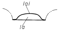
払拭体1は、塵や埃等の汚れを拭き取るためのもので、後述する第1の棒状部材12と第2の棒状部材13の差し込みを受けれる受入口1aを有する受入部の部材1a1に、例えば、短繊維を撚って形成した細い紡績糸を複数本撚り合わせて得られる太いモップ糸を複数本房状に取り付けたもの、又は、毛羽立った合成樹脂製の不織布を束ねられたもの等を取り付けて形成する。
なお、受入部の部材1a1は、袋状に形成され、表側部材と裏側部材とを略中央の長手方向に沿って溶着等して結合している。溶着等により結合されている部位は、図6及び図8に示すXである。
The wiping body 1 is for wiping off dirt such as dust and dirt, and the receiving member 1a1 having a receiving port 1a for receiving insertion of a first rod-
In addition, the member 1a1 of a receiving part is formed in a bag shape, and has joined the front side member and the back side member by welding etc. along the longitudinal direction of the approximate center. The site | part couple | bonded by welding etc. is X shown in FIG.6 and FIG.8.
ハンディモップの柄10は、例えば、ABS樹脂、PP樹脂などの合成樹脂で後述する第1の棒状部材12、第2の棒状部材13及び回動部材14等と共に、一体成形され、手で握る握り部を有する本体11と、この本体11に設けられ(例えば、本体11に一体的に設けられ)、払拭体1の受入部1aに差し込む長手方向に長い棒状の第1の棒状部材12と、この第1の棒状部材12に間隔を有して沿うと共に、本体11に設けられ(例えば、本体11に一体的に設けられ)、払拭体1の受入部1aに差し込む長手方向に長い棒状の第2の棒状部材13と、本体11に回動自在に支持された回動部材14と、この回動部材14に設けられ、回動部材14の第1の棒状部材12の側に張り出す第1の張り出し部材15と、回動部材14に設けられ、回動部材14の第2の棒状部材13の側に張り出す第2の張り出し部材16とを有している。
そして、図3に示すように、回動部材14の本体11の取付部位Aは、第1の棒状部材12の本体11の取付部位Bと第2の棒状部材13の本体11の取付部位Cとの間に位置している。
また、図4に示すように、回動部材14のヒンジ部hに近い側の端部に突起14Aが設けられている。
なお、第1の棒状部材12と第2の棒状部材13が対向する面は、図3及び図13に示すように、第1の棒状部材12の第1の面12Aと第2の棒状部材13の第1の面13Aであり、また、図14に示すように、受入部の部材1a1を介して第1の張り出し部材15に接触する第1の棒状部材12の部位は、第1の棒状部材12の第1の面12Aより突出する第1の凸12A1であり、また、受入部の部材1a1を介して第2の張り出し部材16に接触する第2の棒状部材13の部位は、第2の棒状部材13の第1の面13Aより突出する第2の凸部13A1である。突出する第1の凸12A1、第2の凸部13A1の分、第1の棒状部材12及び第2の棒状部材13の材料費を安く抑えることができる。
なお、場合により、第1の凸部12A1を第1の張り出し部材12の第1の面12Aと同面、第2の凸部13A1を第2の張り出し部材13の第1の面13Aと同面、としても良い。
The
And as shown in FIG. 3, the attachment site | part A of the
Further, as shown in FIG. 4, a
In addition, the surface where the 1st rod-shaped
In some cases, the first convex portion 12A1 is the same surface as the
従って、図9に示すように、払拭体1の受入部1aに第1の棒状部材12と第2の棒状部材13を入れ、払拭体1に第1の棒状部材12と第2の棒状部材13を入れた状態(図10及び図11参照)で、回動部材14を第1の棒状部材12と第2の棒状部材13の間に向かって回動させ(図10に示す矢印方向に回動)、第1の張り出し部材15と第2の張り出し部材16により、受入部の部材1a1を介して第1の棒状部材12と第2の棒状部材13の間を押し広げ、第1の張り出し部材15と第1の棒状部材12、第2の張り出し部材16と第2の棒状部材13により、それぞれ受入部の部材1a1を挟持させて、払拭体1を第1の棒状部材12及び第2の棒状部材13に保持させることができる(図12乃至図14参照)。
また、図12及び図15に示すように、回動部材14の突起14Aが払拭体1の受入部の部材1a1に食い込むため、払拭体1が使用中本体11からより離脱しにくく、使用勝手を向上させることができる。
Therefore, as shown in FIG. 9, the first rod-shaped
Also, as shown in FIGS. 12 and 15, since the
その結果、上述のハンディモップH(ハンディモップの払拭体の保持方法)によれば、払拭体1の受入口1aに第1の棒状部材12と第2の棒状部材13を入れた状態で、回動部材14を第1の棒状部材12と第2の棒状部材13の間に向かって回動させ、第1の張り出し部材15と第2の張り出し部材16により、受入部の部材1a1を介して第1の棒状部材12と第2の棒状部材13の間を押し広げ、第1の張り出し部材15と第1の棒状部材12、第2の張り出し部材16と第2の棒状部材13により、それぞれ受入部の部材1a1を挟持させて、払拭体1を第1の棒状部材12及び第2の棒状部材13に保持させるため、第1の棒状部材12と第2の棒状部材13が元に戻ろうとする弾性力を利用して、払拭体1が使用中第1の棒状部材12及び第2の棒状部材13から離脱しにくく、使用勝手を向上させることができる。
As a result, according to the above-described handy mop H (a method of holding the handy mop wiping body), the first rod-
H ハンディモップ
1 払拭体
1a 受入口
1a1 受入部の部材
11 本体
12 第1の棒状部材
13 第2の棒状部材
14 回動部材
15 第1の張り出し部材
16 第2の張り出し部材
A 取付部位
B 取付部位
C 取付部位
H Handy mop 1 Wiping body 1a Receiving port 1a1 Receiving
Claims (6)
手で握る握り部を有する本体と、
この本体に設けられる棒状の第1の棒状部材と、
この第1の棒状部材に間隔を有して沿うと共に、前記本体に設けられる棒状の第2の
棒状部材と、
前記払拭体に設けられ、前記第1の棒状部材と前記第2の棒状部材の差し込みを受け
れる受入口を有する受入部と、
前記本体に回動自在に支持される回動部材と、
この回動部材に設けられ、前記回動部材の前記第1の棒状部材の側に張り出す第1の
張り出し部材と、
前記回動部材に設けられ、前記回動部材の前記第2の棒状部材の側に張り出す第2の
張り出し部材とを有し、
前記回動部材の前記本体への取付部位は、前記第1の棒状部材の前記本体への取付部位と前記第2の棒状部材の前記本体への取付部位との間に位置し、
前記受入口に前記第1の棒状部材と前記第2の棒状部材を入れた状態で、前記回動部
材を前記第1の棒状部材と前記第2の棒状部材の間に向かって回動させ、前記第1の張り
出し部材と前記第2の張り出し部材により、前記受入部の部材を介して前記第1の棒状部
材と前記第2の棒状部材の間を押し広げ、前記第1の張り出し部材と前記第1の棒状部材
、前記第2の張り出し部材と前記第2の棒状部材により、それぞれ前記受入部の部材を挟
持させて、前記払拭体を前記第1の棒状部材及び第2の棒状部材に保持させる
ことを特徴とするハンディモップ。 A wiping body for wiping off dirt such as dust,
A main body having a grip portion gripped by a hand;
A rod-shaped first rod-shaped member provided in the main body;
Along the first rod-shaped member with a gap, a rod-shaped second rod-shaped member provided on the main body,
A receiving portion provided on the wiping body and having a receiving port for receiving insertion of the first rod-shaped member and the second rod-shaped member;
A rotating member rotatably supported by the main body;
A first projecting member provided on the pivot member and projecting to the first rod-shaped member side of the pivot member;
A second projecting member provided on the pivot member and projecting to the second rod-shaped member side of the pivot member;
Wherein said mounting portion of the main body of the rotating member is positioned between the attachment site to the body of said first rod-like member mounting portion and the second rod-like member to the body,
In a state where the first rod-shaped member and the second rod-shaped member are put in the receiving port, the rotating member is rotated toward the space between the first rod-shaped member and the second rod-shaped member, The first projecting member and the second projecting member push and spread between the first bar-shaped member and the second bar-shaped member via the member of the receiving portion, and the first projecting member and the second projecting member The first bar-shaped member, the second projecting member, and the second bar-shaped member hold the wiping body between the first bar-shaped member and the second bar-shaped member, respectively. A handy mop characterized by
の棒状部材の第1の面であり、
受入部の部材を介して前記第1の張り出し部材に接触する第1の棒状部材の部位は、
前記第1の棒状部材の第1の面より突出する第1の凸部であり、
受入部の部材を介して前記第2の張り出し部材に接触する第2の棒状部材の部位は、
前記第2の棒状部材の第1の面より突出する第2の凸部である
ことを特徴とする請求項1記載のハンディモップ。 The surface where the first rod-shaped member and the second rod-shaped member face each other is the first surface of the first rod-shaped member and the second surface
A first surface of the rod-shaped member of
The portion of the first rod-shaped member that contacts the first projecting member via the member of the receiving portion is:
A first protrusion protruding from the first surface of the first bar-shaped member;
The portion of the second rod-shaped member that contacts the second projecting member via the member of the receiving portion is:
The handy mop according to claim 1, wherein the handy mop is a second convex portion protruding from the first surface of the second rod-shaped member.
前記回動部材と前記ヒンジ部と前記本体は、同一の合成樹脂で形成され、
前記回動部材の前記ヒンジ部に近い側の端部に突起が設けられ、
受入部に第1の棒状部材と第2の棒状部材を入れた状態で、前記回動部材を第1の棒
状部材と第2の棒状部材の間に向かって回動させ、第1の張り出し部材と第2の張り出し
部材により、前記受入部の部材を介して前記第1の棒状部材と前記第2の棒状部材の間を
押し広げ、前記第1の張り出し部材と前記第1の棒状部材、前記第2の張り出し部材と前
記第2の棒状部材により、それぞれ前記受入部の部材を挟持させると共に、前記突起が払
拭体に食い込む
ことを特徴とする請求項1記載のハンディモップ。 The rotating member is connected to the main body by a hinge portion,
The rotating member, the hinge portion, and the main body are formed of the same synthetic resin,
A protrusion is provided at the end of the rotating member on the side close to the hinge portion,
In a state where the first rod-like member and the second rod-like member are put in the receiving portion, the turning member is turned between the first rod-like member and the second rod-like member, and the first projecting member And the second projecting member, the first projecting member and the first projecting member, the first projecting member and the first projecting member, The handy mop according to claim 1, wherein the member of the receiving portion is sandwiched between the second projecting member and the second bar-shaped member, and the protrusion bites into the wiping body.
手で握る握り部を有する本体と、
この本体に設けられる棒状の第1の棒状部材と、
この第1の棒状部材に間隔を有して沿うと共に、前記本体に設けられる棒状の第2の
棒状部材と、
前記払拭体に設けられ、前記第1の棒状部材と前記第2の棒状部材の差し込みを受け
れる受入口を有する受入部と、
前記本体に回動自在に支持される回動部材と、
この回動部材に設けられ、前記回動部材の前記第1の棒状部材の側に張り出す第1の
張り出し部材と、
前記回動部材に設けられ、前記回動部材の前記第2の棒状部材の側に張り出す第2の
張り出し部材とを有し、
前記回動部材の前記本体への取付部位は、前記第1の棒状部材の前記本体への取付部位と前記第2の棒状部材の前記本体への取付部位との間に位置したハンディモップであって、
前記受入口に前記第1の棒状部材と前記第2の棒状部材を入れた状態で、前記回動部
材を前記第1の棒状部材と前記第2の棒状部材の間に向かって回動させ、前記第1の張り
出し部材と前記第2の張り出し部材により、前記受入部の部材を介して前記第1の棒状部
材と前記第2の棒状部材の間を押し広げ、前記第1の張り出し部材と前記第1の棒状部材
、前記第2の張り出し部材と前記第2の棒状部材により、それぞれ前記受入部の部材を挟
持させて、前記払拭体を前記第1の棒状部材及び第2の棒状部材に保持させる
ことを特徴とするハンディモップの払拭体の保持方法。 A wiping body for wiping off dirt such as dust,
A main body having a grip portion gripped by a hand;
A rod-shaped first rod-shaped member provided in the main body;
Along the first rod-shaped member with a gap, a rod-shaped second rod-shaped member provided on the main body,
A receiving portion provided on the wiping body and having a receiving port for receiving insertion of the first rod-shaped member and the second rod-shaped member;
A rotating member rotatably supported by the main body;
A first projecting member provided on the pivot member and projecting to the first rod-shaped member side of the pivot member;
A second projecting member provided on the pivot member and projecting to the second rod-shaped member side of the pivot member;
Wherein said mounting portion of the main body of the rotating member, a handy mop which is located between the mounting portion to the body of the first rod-like member mounting portion and the second rod-like member to the body And
In a state where the first rod-shaped member and the second rod-shaped member are put in the receiving port, the rotating member is rotated toward the space between the first rod-shaped member and the second rod-shaped member, The first projecting member and the second projecting member push and spread between the first bar-shaped member and the second bar-shaped member via the member of the receiving portion, and the first projecting member and the second projecting member The first bar-shaped member, the second projecting member, and the second bar-shaped member hold the wiping body between the first bar-shaped member and the second bar-shaped member, respectively. A method of holding a handy mop wiping body, characterized in that:
この本体に設けられ、払拭体の受入口に差し込む棒状の第1の棒状部材と、
この第1の棒状部材に間隔を有して沿うと共に、前記本体に設けられ、前記払拭体の
受入口に差し込む棒状の第2の棒状部材と、
前記本体に回動自在に支持された回動部材と、
この回動部材に設けられ、前記回動部材の前記第1の棒状部材の側に張り出す第1の
張り出し部材と、
前記回動部材に設けられ、前記回動部材の前記第2の棒状部材の側に張り出す第2の
張り出し部材とを有し、
前記回動部材の前記本体への取付部位は、前記第1の棒状部材の前記本体への取付部位と前記第2の棒状部材の前記本体への取付部位との間に位置し、
前記回動部材を前記第1の棒状部材と前記第2の棒状部材の間に向かって回動させ、
前記第1の張り出し部材と前記第2の張り出し部材により、前記第1の棒状部材と前記第
2の棒状部材の間を押し広げるものである
ことを特徴とするハンディモップの柄。 A main body having a grip portion gripped by a hand;
A rod-shaped first rod-shaped member provided in the main body and inserted into the receiving port of the wiping body;
Along the first rod-shaped member with a gap, the rod-shaped second rod-shaped member provided in the main body and inserted into the receiving port of the wiping body,
A rotating member rotatably supported by the main body;
A first projecting member provided on the pivot member and projecting to the first rod-shaped member side of the pivot member;
A second projecting member provided on the pivot member and projecting to the second rod-shaped member side of the pivot member;
Wherein said mounting portion of the main body of the rotating member is positioned between the attachment site to the body of said first rod-like member mounting portion and the second rod-like member to the body,
Rotating the rotating member between the first rod-shaped member and the second rod-shaped member;
The first projecting member and the second projecting member push the space between the first bar-shaped member and the second bar-shaped member.
Handy mop pattern characterized by that.
前記回動部材と前記ヒンジ部と前記本体は、同一の合成樹脂で形成され、
前記回動部材の前記ヒンジ部に近い側の端部に突起が設けられている
ことを特徴とする請求項5記載のハンディモップの柄。 The rotating member is connected to the main body by a hinge portion,
The rotating member, the hinge portion, and the main body are formed of the same synthetic resin,
The handle of the handy mop according to claim 5, wherein a protrusion is provided at an end portion of the rotating member on a side close to the hinge portion.
Priority Applications (1)
| Application Number | Priority Date | Filing Date | Title |
|---|---|---|---|
| JP2012073058A JP6045058B2 (en) | 2012-03-28 | 2012-03-28 | Handy mop, handy mop wiping body holding method and handy mop handle |
Applications Claiming Priority (1)
| Application Number | Priority Date | Filing Date | Title |
|---|---|---|---|
| JP2012073058A JP6045058B2 (en) | 2012-03-28 | 2012-03-28 | Handy mop, handy mop wiping body holding method and handy mop handle |
Publications (2)
| Publication Number | Publication Date |
|---|---|
| JP2013202155A JP2013202155A (en) | 2013-10-07 |
| JP6045058B2 true JP6045058B2 (en) | 2016-12-14 |
Family
ID=49521908
Family Applications (1)
| Application Number | Title | Priority Date | Filing Date |
|---|---|---|---|
| JP2012073058A Active JP6045058B2 (en) | 2012-03-28 | 2012-03-28 | Handy mop, handy mop wiping body holding method and handy mop handle |
Country Status (1)
| Country | Link |
|---|---|
| JP (1) | JP6045058B2 (en) |
Families Citing this family (1)
| Publication number | Priority date | Publication date | Assignee | Title |
|---|---|---|---|---|
| JP6474559B2 (en) * | 2014-08-06 | 2019-02-27 | 花王株式会社 | Cleaning tool |
Family Cites Families (5)
| Publication number | Priority date | Publication date | Assignee | Title |
|---|---|---|---|---|
| JPH0420384Y2 (en) * | 1985-04-22 | 1992-05-11 | ||
| JP2549043Y2 (en) * | 1992-05-22 | 1997-09-24 | 株式会社エルゼ | Mop cleaning tools |
| JP3043196B2 (en) * | 1992-12-24 | 2000-05-22 | 日本化薬株式会社 | Method for deodorizing chitin or chitosan |
| RU2262291C2 (en) * | 2000-10-27 | 2005-10-20 | Юни-Чарм Корпорейшн | Wiping device convenient in use |
| JP5114231B2 (en) * | 2008-01-31 | 2013-01-09 | 株式会社サニクリーン | Cleaning member and cleaning tool provided with the cleaning member |
-
2012
- 2012-03-28 JP JP2012073058A patent/JP6045058B2/en active Active
Also Published As
| Publication number | Publication date |
|---|---|
| JP2013202155A (en) | 2013-10-07 |
Similar Documents
| Publication | Publication Date | Title |
|---|---|---|
| JP4050035B2 (en) | Handy mop | |
| US8719990B2 (en) | Floor cleaning apparatus | |
| US20110162157A1 (en) | Apparatus for holding a cleaning sheet in a cleaning implement | |
| JP6045058B2 (en) | Handy mop, handy mop wiping body holding method and handy mop handle | |
| JP2005144199A (en) | Handy mop | |
| US20190059681A1 (en) | Combination mop and broom | |
| US20140033461A1 (en) | Mopping device | |
| US7260864B1 (en) | Attachment mechanism to removably and securely retain a cleaning implement attachment on a wringer mop | |
| KR101270723B1 (en) | Pad replaceable mop | |
| KR100816872B1 (en) | Multi cleaner | |
| KR20190026396A (en) | Fixed tool of wet type cleaner | |
| JPH10117985A (en) | Mop | |
| JP3160495U (en) | Replaceable mop for cleaning equipment | |
| US5416945A (en) | Sponge mop backing plate and method of attaching scrubber strip | |
| JP2013075036A (en) | Cleaning tool | |
| JP6440965B2 (en) | Surface cleaning tool | |
| JP4761974B2 (en) | Mop support | |
| US2932049A (en) | Holder for floor and wall cleaning devices | |
| JP4873608B2 (en) | Mop support | |
| JP3155215U (en) | Flooring wiper | |
| KR101742034B1 (en) | Wet type cleaner | |
| CN201012076Y (en) | Cleaning tool combined base of collodion mop | |
| JP2023064809A (en) | Cleaning body and cleaning body use method | |
| WO2020137512A1 (en) | Cleaning implement | |
| KR200379429Y1 (en) | Mop mop for easy separation and joining |
Legal Events
| Date | Code | Title | Description |
|---|---|---|---|
| A621 | Written request for application examination |
Free format text: JAPANESE INTERMEDIATE CODE: A621 Effective date: 20150120 |
|
| A977 | Report on retrieval |
Free format text: JAPANESE INTERMEDIATE CODE: A971007 Effective date: 20151026 |
|
| A131 | Notification of reasons for refusal |
Free format text: JAPANESE INTERMEDIATE CODE: A131 Effective date: 20151110 |
|
| A521 | Written amendment |
Free format text: JAPANESE INTERMEDIATE CODE: A523 Effective date: 20151117 |
|
| A131 | Notification of reasons for refusal |
Free format text: JAPANESE INTERMEDIATE CODE: A131 Effective date: 20160517 |
|
| A521 | Written amendment |
Free format text: JAPANESE INTERMEDIATE CODE: A523 Effective date: 20160531 |
|
| TRDD | Decision of grant or rejection written | ||
| A01 | Written decision to grant a patent or to grant a registration (utility model) |
Free format text: JAPANESE INTERMEDIATE CODE: A01 Effective date: 20161025 |
|
| A61 | First payment of annual fees (during grant procedure) |
Free format text: JAPANESE INTERMEDIATE CODE: A61 Effective date: 20161111 |
|
| R150 | Certificate of patent or registration of utility model |
Ref document number: 6045058 Country of ref document: JP Free format text: JAPANESE INTERMEDIATE CODE: R150 |