JP6032524B2 - Belt drive device, transfer device, and image forming apparatus - Google Patents
Belt drive device, transfer device, and image forming apparatus Download PDFInfo
- Publication number
- JP6032524B2 JP6032524B2 JP2012014511A JP2012014511A JP6032524B2 JP 6032524 B2 JP6032524 B2 JP 6032524B2 JP 2012014511 A JP2012014511 A JP 2012014511A JP 2012014511 A JP2012014511 A JP 2012014511A JP 6032524 B2 JP6032524 B2 JP 6032524B2
- Authority
- JP
- Japan
- Prior art keywords
- speed
- belt
- roller
- driving
- belt member
- Prior art date
- Legal status (The legal status is an assumption and is not a legal conclusion. Google has not performed a legal analysis and makes no representation as to the accuracy of the status listed.)
- Expired - Fee Related
Links
- 238000012546 transfer Methods 0.000 title claims description 206
- 238000001514 detection method Methods 0.000 claims description 76
- 238000000034 method Methods 0.000 claims description 67
- 230000002159 abnormal effect Effects 0.000 claims description 33
- 230000005856 abnormality Effects 0.000 claims description 30
- 230000008569 process Effects 0.000 claims description 28
- 238000004804 winding Methods 0.000 claims description 21
- 230000008859 change Effects 0.000 claims description 20
- 238000012937 correction Methods 0.000 claims description 15
- 238000011144 upstream manufacturing Methods 0.000 claims description 10
- 230000002093 peripheral effect Effects 0.000 claims description 5
- 239000000969 carrier Substances 0.000 claims description 4
- 239000003086 colorant Substances 0.000 claims description 3
- 238000010586 diagram Methods 0.000 description 22
- 238000012545 processing Methods 0.000 description 16
- 108091008695 photoreceptors Proteins 0.000 description 12
- 230000001276 controlling effect Effects 0.000 description 9
- 239000010410 layer Substances 0.000 description 9
- 230000000630 rising effect Effects 0.000 description 9
- 239000000463 material Substances 0.000 description 8
- 230000003287 optical effect Effects 0.000 description 8
- 238000006243 chemical reaction Methods 0.000 description 7
- 238000004140 cleaning Methods 0.000 description 7
- 239000011521 glass Substances 0.000 description 7
- 230000005684 electric field Effects 0.000 description 6
- 238000002474 experimental method Methods 0.000 description 6
- 238000005259 measurement Methods 0.000 description 6
- 229910052751 metal Inorganic materials 0.000 description 6
- 239000002184 metal Substances 0.000 description 6
- 239000002245 particle Substances 0.000 description 6
- 238000003756 stirring Methods 0.000 description 5
- 229910052782 aluminium Inorganic materials 0.000 description 4
- XAGFODPZIPBFFR-UHFFFAOYSA-N aluminium Chemical compound [Al] XAGFODPZIPBFFR-UHFFFAOYSA-N 0.000 description 4
- 238000011161 development Methods 0.000 description 4
- 230000008030 elimination Effects 0.000 description 4
- 238000003379 elimination reaction Methods 0.000 description 4
- 229920000840 ethylene tetrafluoroethylene copolymer Polymers 0.000 description 4
- 238000013500 data storage Methods 0.000 description 3
- 239000000314 lubricant Substances 0.000 description 3
- 238000001579 optical reflectometry Methods 0.000 description 3
- 230000036961 partial effect Effects 0.000 description 3
- 230000003068 static effect Effects 0.000 description 3
- 238000012360 testing method Methods 0.000 description 3
- BQCIDUSAKPWEOX-UHFFFAOYSA-N 1,1-Difluoroethene Chemical compound FC(F)=C BQCIDUSAKPWEOX-UHFFFAOYSA-N 0.000 description 2
- XEEYBQQBJWHFJM-UHFFFAOYSA-N Iron Chemical compound [Fe] XEEYBQQBJWHFJM-UHFFFAOYSA-N 0.000 description 2
- 239000002033 PVDF binder Substances 0.000 description 2
- 229910052799 carbon Inorganic materials 0.000 description 2
- 239000003638 chemical reducing agent Substances 0.000 description 2
- 238000013461 design Methods 0.000 description 2
- 238000006073 displacement reaction Methods 0.000 description 2
- XUCNUKMRBVNAPB-UHFFFAOYSA-N fluoroethene Chemical compound FC=C XUCNUKMRBVNAPB-UHFFFAOYSA-N 0.000 description 2
- 238000012986 modification Methods 0.000 description 2
- 230000004048 modification Effects 0.000 description 2
- 239000004417 polycarbonate Substances 0.000 description 2
- 229920001343 polytetrafluoroethylene Polymers 0.000 description 2
- 239000004810 polytetrafluoroethylene Substances 0.000 description 2
- 229920002981 polyvinylidene fluoride Polymers 0.000 description 2
- 230000001737 promoting effect Effects 0.000 description 2
- 238000004064 recycling Methods 0.000 description 2
- 239000007787 solid Substances 0.000 description 2
- 230000036962 time dependent Effects 0.000 description 2
- 230000037303 wrinkles Effects 0.000 description 2
- 229920001774 Perfluoroether Polymers 0.000 description 1
- 239000004642 Polyimide Substances 0.000 description 1
- 238000013459 approach Methods 0.000 description 1
- 230000015572 biosynthetic process Effects 0.000 description 1
- 238000004364 calculation method Methods 0.000 description 1
- 239000006229 carbon black Substances 0.000 description 1
- 238000005266 casting Methods 0.000 description 1
- 210000000078 claw Anatomy 0.000 description 1
- 239000011248 coating agent Substances 0.000 description 1
- 238000000576 coating method Methods 0.000 description 1
- 239000004020 conductor Substances 0.000 description 1
- 230000008602 contraction Effects 0.000 description 1
- 229920001577 copolymer Polymers 0.000 description 1
- 230000006866 deterioration Effects 0.000 description 1
- 230000000694 effects Effects 0.000 description 1
- 230000002708 enhancing effect Effects 0.000 description 1
- 238000010438 heat treatment Methods 0.000 description 1
- 229910052742 iron Inorganic materials 0.000 description 1
- 238000012423 maintenance Methods 0.000 description 1
- 239000003550 marker Substances 0.000 description 1
- 238000000465 moulding Methods 0.000 description 1
- 239000002365 multiple layer Substances 0.000 description 1
- 238000006386 neutralization reaction Methods 0.000 description 1
- 238000005192 partition Methods 0.000 description 1
- 229920000515 polycarbonate Polymers 0.000 description 1
- 229920001721 polyimide Polymers 0.000 description 1
- -1 polytetrafluoroethylene Polymers 0.000 description 1
- 239000000843 powder Substances 0.000 description 1
- 238000002360 preparation method Methods 0.000 description 1
- 238000003825 pressing Methods 0.000 description 1
- 238000011084 recovery Methods 0.000 description 1
- 230000001105 regulatory effect Effects 0.000 description 1
- 239000011347 resin Substances 0.000 description 1
- 229920005989 resin Polymers 0.000 description 1
- 239000000523 sample Substances 0.000 description 1
- 238000007790 scraping Methods 0.000 description 1
- 238000000926 separation method Methods 0.000 description 1
- 239000002356 single layer Substances 0.000 description 1
- 229910001220 stainless steel Inorganic materials 0.000 description 1
- 239000010935 stainless steel Substances 0.000 description 1
- 239000000126 substance Substances 0.000 description 1
- 230000001360 synchronised effect Effects 0.000 description 1
- 230000008685 targeting Effects 0.000 description 1
- 230000002123 temporal effect Effects 0.000 description 1
- 238000013518 transcription Methods 0.000 description 1
- 230000035897 transcription Effects 0.000 description 1
Images


Landscapes
- Electrostatic Charge, Transfer And Separation In Electrography (AREA)
- Delivering By Means Of Belts And Rollers (AREA)
Description
本発明は、無端状のベルト部材を複数の張架部材によって張架しながら無端移動させるベルト駆動装置、並びにこれを用いる転写装置及び画像形成装置に関するものである。 The present invention relates to a belt driving device that moves an endless belt member endlessly while being stretched by a plurality of stretching members, and a transfer device and an image forming apparatus using the belt driving device.
従来、この種の画像形成装置としては、特許文献1に記載のものが知られている。この画像形成装置は、周知の電子写真プロセスによってドラム状の感光体の表面にトナー像を形成する。そして、感光体上のトナー像を転写装置によって記録シートに転写する。転写装置は、複数の張架ローラによって無端状の中間転写ベルトを張架しながら無端移動させるベルト駆動装置を具備しており、感光体上のトナー像を中間転写ベルトのおもて面(ループ外面)に1次転写した後、記録シートに2次転写する。
Conventionally, as this type of image forming apparatus, the one described in
このようにして転写を行う過程で、中間転写ベルトの速度については、スケールセンサーによる検知結果に基づいて制御している。具体的には、中間転写ベルトの幅方向における一端部には、ベルト周方向に所定のピッチで並ぶ複数のスケールマークを具備するスケールが設けられている。転写装置の制御部は、それらのスケールマークを反射型光学センサーからなるスケールセンサーによって検知する周期が所定の周期になるように、ベルト駆動モータの駆動速度を制御することで、中間転写ベルトを目標速度で無端移動させている。 In the process of transferring in this way, the speed of the intermediate transfer belt is controlled based on the detection result by the scale sensor. Specifically, a scale having a plurality of scale marks arranged at a predetermined pitch in the belt circumferential direction is provided at one end in the width direction of the intermediate transfer belt. The control unit of the transfer device controls the belt drive motor drive speed so that the scale marks detected by the scale sensor composed of the reflective optical sensor become a predetermined cycle, thereby targeting the intermediate transfer belt. It is moving endlessly at speed.
かかる構成において、トナーや汚れの付着によって光反射性を著しく低下させたスケールマークが発生すると、そのスケールマークがスケールセンサーによって検知されなくなることから、中間転写ベルトの速度が正しく検知されなくなってしまう。そこで、特許文献1に記載の画像形成装置は、スケールセンサーによってスケールマークが検知される周期が急激に変化した場合に、スケール異常が発生しているものと判断する。そして、スケール異常が発生した場合には、ベルト駆動方式を、スケールセンサーによる検知結果に基づく正常時用駆動方式から、異常時用駆動方式に切り替える。異常時用駆動方式では、ベルト駆動モータの回転速度をエンコーダによって検知しながら、その結果が所定の値になるように、ベルト駆動モータの駆動速度を調整する。これにより、スケールマークに異常をきたした場合であっても、中間転写ベルトを安定した速度で駆動することができる。
In such a configuration, when a scale mark having a significantly reduced light reflectivity due to adhesion of toner or dirt is generated, the scale mark is not detected by the scale sensor, so that the speed of the intermediate transfer belt is not correctly detected. Therefore, the image forming apparatus described in
しかしながら、このような異常時駆動方式では、駆動ローラの径の誤差に起因して、中間転写ベルトの速度を目標速度からずらしてしまうという問題があった。具体的には、駆動ローラは、中間転写ベルトのループ内側に配設され、自らの表面にベルトを掛け回した状態でベルト駆動モータによる駆動力を受けて回転駆動することで中間転写ベルトを無端移動させるものである。この駆動ローラの径に加工誤差がない場合には、ベルト駆動モータを所定速度で回転させることで、駆動ローラを所定の線速で回転させることが可能である。そして、中間転写ベルトを目標速度で無端移動させることができる。ところが、加工精度の限界から、駆動ローラの径にはどうしても加工誤差が生じてしまう。すると、ベルト駆動モータを所定速度で回転させても、駆動ローラの線速が所定の速度にならないため、中間転写ベルトの速度が目標速度からずれてしまうのである。 However, such an abnormal driving method has a problem that the speed of the intermediate transfer belt is shifted from the target speed due to an error in the diameter of the driving roller. Specifically, the driving roller is disposed inside the loop of the intermediate transfer belt, and rotates the endless belt by receiving a driving force from a belt driving motor while the belt is wound around its surface. It is to be moved. When there is no processing error in the diameter of the drive roller, the drive roller can be rotated at a predetermined linear speed by rotating the belt drive motor at a predetermined speed. Then, the intermediate transfer belt can be moved endlessly at the target speed. However, due to the limit of processing accuracy, a processing error necessarily occurs in the diameter of the drive roller. Then, even if the belt drive motor is rotated at a predetermined speed, the linear speed of the drive roller does not become a predetermined speed, and the speed of the intermediate transfer belt deviates from the target speed.
なお、正常時駆動方式において、スケールセンサーによる検知結果に基づいて中間転写ベルトの速度を把握する構成について説明したが、ベルトに追従して従動回転する従動ローラなどの追従部材の速度に基づいて中間転写ベルトの速度を把握する構成でも、同様の問題が生じ得る。 In the normal driving method, the configuration for grasping the speed of the intermediate transfer belt based on the detection result by the scale sensor has been described, but the intermediate driving belt is driven based on the speed of a follower member such as a driven roller that follows the belt and rotates. A similar problem may occur even in a configuration in which the speed of the transfer belt is grasped.
また、異常時駆動方式において、ベルト駆動モータの回転速度に基づいてベルト駆動モータの駆動速度を制御する構成について説明したが、駆動ローラの回転速度に基づいてベルト駆動モータの駆動速度を制御する構成においても、同様の問題が生じ得る。 In the abnormal driving method, the configuration for controlling the driving speed of the belt driving motor based on the rotational speed of the belt driving motor has been described. The configuration for controlling the driving speed of the belt driving motor based on the rotational speed of the driving roller. A similar problem may occur in
また、中間転写ベルトを用いる画像形成装置について説明したが、無端状のベルト部材を駆動するベルト駆動装置であれば、駆動ローラの径の加工誤差に起因するベルト速度のずれという同様の問題が生ずる。 Further, the image forming apparatus using the intermediate transfer belt has been described. However, in the case of a belt driving apparatus that drives an endless belt member, a similar problem of belt speed deviation caused by a processing error in the diameter of the driving roller occurs. .
本発明は、以上の背景に鑑みてなされたものであり、その目的とするところは、次のようなベルト駆動装置、並びにこれを用いる転写装置及び画像形成装置を提供することである。即ち、異常時駆動方式において、駆動ローラの径の加工誤差に起因するベルト速度の目標速度からのずれを低減することができるベルト駆動装置等である。 The present invention has been made in view of the above background, and an object of the present invention is to provide the following belt driving device, and a transfer device and an image forming apparatus using the belt driving device. That is, a belt driving device or the like that can reduce the deviation of the belt speed from the target speed due to a processing error in the diameter of the driving roller in the abnormal driving method.
上記目的を達成するために、本発明は、無端状のベルト部材と、前記ベルト部材のループ内側で前記ベルト部材を支持しながら張架する複数の張架部材と、複数の張架部材の1つであり、自らの回転駆動に伴って前記ベルト部材を無端移動させる駆動ローラと、前記ベルト部材の表面移動速度、又は前記ベルト部材の無端移動に追従する従動部材の速度を検知する第1速度検知手段と、前記駆動ローラの回転速度、又は前記駆動ローラの駆動源である駆動モータの回転速度を検知する第2速度検知手段と、前記第1速度検知手段や前記第2速度検知手段による速度の検知結果に基づいて、前記駆動モータの駆動速度を制御して前記ベルト部材の移動速度を調整する制御手段とを備え、前記制御手段が、前記第1速度検知手段による速度の検知結果である第1検知結果について異常なしと判定した場合には、前記第1検知結果、又は、前記第1検知結果に基づく所定の第1算出値と、所定の第1目標値との比較に基づいて前記駆動モータの駆動速度を制御する正常時用駆動方式を採用する一方で、前記第1検知結果について異常ありと判定した場合には、前記第2速度検知手段による速度の検知結果である第2検知結果、又は、前記第2検知結果に基づく所定の第2算出値と、所定の第2目標値との比較に基づいて前記駆動モータの駆動速度を制御する異常時用制御方式を採用するものであるベルト駆動装置において、前記第1検知結果に異常がない状態で、前記第2検知結果又は前記第2算出値と前記第2目標値との比較に基づいて前記駆動モータの駆動速度を制御しながら、複数の前記第1検知結果を取得し、それら複数の前記第1検知結果に基づいて前記ベルト部材の平均速度を算出した後、前記平均速度と前記第1目標値との比較結果に基づいて、前記異常時用制御方式で前記ベルト部材を前記第1目標値と同じ移動速度で駆動し得る値に前記第2目標値を補正する目標値補正処理を所定のタイミングで実施するように、前記制御手段を構成したことを特徴とするものである。 To achieve the above object, the present invention provides an endless belt member, a plurality of stretching members that support the belt member while supporting the belt member inside a loop of the belt member, and one of the plurality of stretching members. And a first speed for detecting the speed of the surface movement of the belt member or the follower member following the endless movement of the belt member. and detecting means, speed of rotation speed or a second speed detecting means for detecting a rotational speed of the drive motor is a drive source of the drive roller, the first speed detecting means and the second speed detecting means of the drive roller based on the detection result, controls the driving speed of said drive motor and control means for adjusting a moving speed of the belt member, wherein the control means detects the speed of the first speed detecting means When it is determined that there is no abnormality in the first detection result that is the result, the first detection result or a predetermined first calculated value based on the first detection result is compared with a predetermined first target value. When the normal driving method for controlling the driving speed of the drive motor based on the above is adopted, and the first detection result is determined to be abnormal , the detection result of the speed by the second speed detection means. Employs an abnormal time control method for controlling the drive speed of the drive motor based on a comparison between a second detection result or a predetermined second calculated value based on the second detection result and a predetermined second target value. In the belt drive device, the drive speed of the drive motor is determined based on a comparison between the second detection result or the second calculated value and the second target value in a state where there is no abnormality in the first detection result. while controlling the multiple Acquiring the first detection result, after calculating the average speed of the belt member based on a plurality of the first detection result, based on a comparison result between the average speed and the first target value, the abnormality The control means is configured to execute a target value correction process for correcting the second target value at a predetermined timing so that the belt member can be driven at the same moving speed as the first target value in a temporal control method. It is characterized by comprising.
本発明では、目標値補正処理において、駆動ローラの回転速度を反映している第2検知結果又は第2算出値を第2目標値と同じにするように駆動モータの駆動速度を制御すると、駆動ローラの径の加工誤差に起因して、ベルト部材が目標速度からずれた速度で無端移動する。そのずれ量を、ベルト速度を反映している第1検知結果又は第1算出値と、第1目標値との差に基づいて把握する。そして、把握結果に基づいて、ベルト速度を反映している第1検知結果又は第1算出値を、第1目標値と同等にできるように、第2目標値を補正する。これにより、第2目標値を、実際の駆動ローラの径に見合った値にすることで、異常時駆動方式において、駆動ローラの径の加工誤差に起因するベルト速度の目標速度からのずれを低減することができる。 In the present invention, when the drive speed of the drive motor is controlled so that the second detection result or the second calculated value reflecting the rotation speed of the drive roller is the same as the second target value in the target value correction processing, Due to the processing error of the roller diameter, the belt member moves endlessly at a speed deviating from the target speed. The amount of deviation is grasped based on the difference between the first detection result or the first calculated value reflecting the belt speed and the first target value. Then, based on the grasp result, the second target value is corrected so that the first detection result or the first calculated value reflecting the belt speed can be made equal to the first target value. This reduces the deviation of the belt speed from the target speed due to a processing error in the diameter of the driving roller in the abnormal driving method by setting the second target value to a value commensurate with the actual diameter of the driving roller. can do.
以下、本発明を、電子写真方式の複写機(以下、単に複写機という)に適用した実施形態について説明する。
まず、本実施形態に係る複写機の基本的な構成について説明する。図1は、実施形態に係る複写機を示す概略構成図である。この複写機は、画像形成装置としての画像形成部1と、白紙供給装置40と、画像読取ユニット50とを備えている。画像読取装置としての画像読取ユニット50は、画像形成部1の上に固定されたスキャナ150と、これに支持されるシート搬送装置としての原稿自動搬送装置(以下、ADFという)51とを有している。
Hereinafter, an embodiment in which the present invention is applied to an electrophotographic copying machine (hereinafter simply referred to as a copying machine) will be described.
First, a basic configuration of the copying machine according to the present embodiment will be described. FIG. 1 is a schematic configuration diagram illustrating a copying machine according to an embodiment. This copier includes an
白紙供給装置40は、ペーパーバンク41内に多段に配設された2つの給紙カセット42、給紙カセットから記録シートを送り出す送出ローラ43、送り出された記録シートを搬送しながら1枚ずつに分離する給紙分離ローラ対45等を有している。また、画像形成部1の搬送路としての給紙路37に、シート部材としての記録シートを搬送する複数の搬送ローラ47等も有している。そして、給紙カセット内の記録シートを画像形成部1内の給紙路37内に給紙する。
The blank
画像形成手段としての画像形成部1は、光書込装置2や、黒,イエロー,マゼンタ,シアン(K,Y,M,C)のトナー像を形成する4つのプロセスユニット3K,Y,M,C、転写ユニット24、紙搬送ユニット28、レジストローラ対33、定着装置34、スイッチバック装置36、給紙路37等を備えている。そして、光書込装置2内に配設された図示しないレーザーダイオードやLED等の光源を駆動して、ドラム状の4つの感光体4K,Y,M,Cに向けてレーザー光Lを照射する。この照射により、感光体4K,Y,M,Cの表面には静電潜像が形成され、この潜像は所定の現像プロセスを経由してトナー像に現像される。
The
図2は、画像形成部1の内部構成の一部を拡大して示す部分構成図である。また、図3は、4つのプロセスユニット3K,Y,M,Cからなるタンデム部の一部を示す部分拡大図である。なお、4つのプロセスユニット3K,Y,M,Cは、それぞれ使用するトナーの色が異なる他はほぼ同様の構成になっているので、図3においては各符号に付すK,Y,M,Cという添字を省略している。
FIG. 2 is an enlarged partial configuration diagram illustrating a part of the internal configuration of the
プロセスユニット3K,Y,M,Cは、それぞれ、感光体とその周囲に配設される各種装置とを1つのユニットとして共通の支持体に支持するものであり、画像形成部1本体に対して着脱可能になっている。黒用のプロセスユニット3Kを例にすると、これは、感光体4の周りに、帯電装置23、現像装置6、ドラムクリーニング装置15、除電ランプ22等を有している。本複写機では、4つのプロセスユニット3K,Y,M,Cを、後述する中間転写ベルト25に対してその無端移動方向に沿って並べるように対向配設した、いわゆるタンデム型の構成になっている。
The
感光体4としては、アルミニウム等の素管に、感光性を有する有機感光材の塗布による感光層を形成したドラム状のものを用いている。但し、無端ベルト状のものを用いても良い。
As the
現像装置6は、図示しない磁性キャリアと非磁性トナーとを含有する二成分現像剤を用いて潜像を現像するようになっている。内部に収容している二成分現像剤を攪拌しながら搬送して現像スリーブ12に供給する攪拌部7と、現像スリーブ12に担持された二成分現像剤中のトナーを感光体4に転移させるための現像部11とを有している。
The developing
攪拌部7は、現像部11よりも低い位置に設けられており、互いに平行配設された2本の搬送スクリュウ8、これらスクリュウ間に設けられた仕切り板、現像ケース9の底面に設けられたトナー濃度センサー10などを有している。
The stirring
現像部11は、現像ケース9の開口を通して感光体4に対向する現像スリーブ12、これの内部に回転不能に設けられたマグネットローラ13、現像スリーブ12に先端を接近させるドクタブレード14などを有している。現像スリーブ12は、非磁性の回転可能な筒状になっている。マグネットローラ12は、ドクタブレード14との対向位置からスリーブの回転方向に向けて順次並ぶ複数の磁極を有している。これら磁極は、それぞれスリーブ上の二成分現像剤に対して回転方向の所定位置で磁力を作用させる。これにより、攪拌部7から送られてくる二成分現像剤を現像スリーブ13表面に引き寄せて担持させるとともに、スリーブ表面上で磁力線に沿った磁気ブラシを形成する。
The developing
磁気ブラシは、現像スリーブ12の回転に伴ってドクタブレード14との対向位置を通過する際に適正な層厚に規制されてから、感光体4に対向する現像領域に搬送される。そして、現像スリーブ12に印加される現像バイアスと、感光体4の静電潜像との電位差によってトナーを静電潜像上に転移させて現像に寄与する。更に、現像スリーブ12の回転に伴って再び現像部11内に戻り、マグネットローラ13の磁極間に形成される反発磁界の影響によってスリーブ表面から離脱した後、攪拌部7内に戻される。攪拌部7内には、トナー濃度センサー10による検知結果に基づいて、二成分現像剤に適量のトナーが補給される。なお、現像装置6として、二成分現像剤を用いるものの代わりに、磁性キャリアを含まない一成分現像剤を用いるものを採用してもよい。
The magnetic brush is regulated to an appropriate layer thickness when passing through the position facing the doctor blade 14 as the developing
ドラムクリーニング装置15としては、弾性体からなるクリーニングブレード16を感光体4に押し当てる方式のものを用いているが、他の方式のものを用いてもよい。クリーニング性を高める目的で、本例では、外周面を感光体4に接触させる接触導電性のファーブラシ17を、図中矢印方向に回転自在に有する方式のものを採用している。このファーブラシ17は、図示しない固形潤滑剤から潤滑剤を掻き取って微粉末にしながら感光体4表面に塗布する役割も兼ねている。ファーブラシ17にバイアスを印加する金属製の電界ローラ18を図中矢示方向に回転自在に設け、これにスクレーパ19の先端を押し当てている。ファーブラシ17に付着したトナーは、ファーブラシ17に対してカウンタ方向に接触して回転しながらバイアスが印加される電界ローラ18に転位する。そして、スクレーパ19によって電界ローラ18から掻き取られた後、回収スクリュウ20上に落下する。回収スクリュウ20は、回収トナーをドラムクリーニング装置15における図紙面と直交する方向の端部に向けて搬送して、外部のリサイクル搬送装置21に受け渡す。リサイクル搬送装置21は、受け渡されたトナーを現像装置15に送ってリサイクルする。
As the
除電ランプ22は、光照射によって感光体4を除電する。除電された感光体4の表面は、帯電装置23によって一様に帯電せしめられた後、光書込装置2による光書込処理がなされる。なお、帯電装置23としては、帯電バイアスが印加される帯電ローラを感光体4に当接させながら回転させるものを用いている。感光体4に対して非接触で帯電処理を行うスコロトロンチャージャ等を用いてもよい。
The
先に示した図2において、4つのプロセスユニット3K,Y,M,Cの感光体4K,Y,M,Cには、これまで説明してきたプロセスによってK,Y,M,Cトナー像が形成される。
In FIG. 2 described above, K, Y, M, and C toner images are formed on the
4つのプロセスユニット3K,Y,M,Cの下方には、転写ユニット24が配設されている。ベルト駆動装置としての転写ユニット24は、複数のローラによって張架した中間転写ベルト25を、感光体4K,Y,M,Cに当接させながら図中時計回り方向に無端移動させる。これにより、感光体4K,Y,M,Cと、無端状のベルト部材である中間転写ベルト25とが当接するK,Y,M,C用の1次転写ニップが形成されている。K,Y,M,C用の1次転写ニップの近傍では、ベルトループ内側に配設された1次転写ローラ26K,Y,M,Cによって中間転写ベルト25を感光体4K,Y,M,Cに向けて押圧している。これら1次転写ローラ26K,Y,M,Cには、それぞれ図示しない電源によって1次転写バイアスが印加されている。これにより、K,Y,M,C用の1次転写ニップには、感光体4K,Y,M,C上のトナー像を中間転写ベルト25に向けて静電移動させる1次転写電界が形成されている。図中時計回り方向の無端移動に伴ってK,Y,M,C用の1次転写ニップを順次通過していく中間転写ベルト25のおもて面には、各1次転写ニップでトナー像が順次重ね合わせて1次転写される。この重ね合わせの1次転写により、中間転写ベルト25のおもて面には4色重ね合わせトナー像(以下、4色トナー像という)が形成される。
A
転写ユニット24の図中下方には、駆動ローラ30と2次転写ローラ31との間に、無端状の紙搬送ベルト29を掛け渡して無端移動させる紙搬送ユニット28が設けられている。そして、自らの2次転写ローラ31と、転写ユニット24の下部張架ローラ27aとの間に、中間転写ベルト25及び紙搬送ベルト29を挟み込んでいる。これにより、中間転写ベルト25のおもて面と、紙搬送ベルト29のおもて面とが当接する2次転写ニップが形成されている。2次転写ローラ31には図示しない電源によって2次転写バイアスが印加されている。一方、転写ユニット24の下部張架ローラ27aは接地されている。これにより、2次転写ニップに2次転写電界が形成されている。
Below the
この2次転写ニップの図中右側方には、レジストローラ対33が配設されている。また、レジストローラ対33のレジストニップの入口付近には、図示しないレジストローラセンサーが配設されている。図示しない白紙供給装置からレジストローラ対33に向けて搬送されてくる記録シートPは、その先端がレジストローラセンサーに検知された所定時間後記録シートPの搬送が一時停止し、レジストローラ対33のレジストニップに先端を突き当てる。この結果、記録シートPの姿勢が修正され、画像形成との同期をとる準備が整う。このようにして、記録シートPは、姿勢が修正されるが、その修正が上手く行われない場合もある。すると、レジストローラ対33の下流側で記録シートPのスキューが発生する。
A
記録シートPの先願がレジストニップに突き当たると、レジストローラ対33は、記録シートPを中間転写ベルト25上の4色トナー像に同期させ得るタイミングでローラ回転駆動を再開して、記録シートPを2次転写ニップに送り出す。2次転写ニップ内では、中間転写ベルト25上の4色トナー像が2次転写電界やニップ圧の影響によって記録シートに一括2次転写され、記録シートの白色と相まってフルカラー画像となる。2次転写ニップを通過した記録シートは、中間転写ベルト25から離間して、紙搬送ベルト29のおもて面に保持されながら、その無端移動に伴って定着装置34へと搬送される。
When the prior application of the recording sheet P hits the registration nip, the
2次転写ニップを通過した中間転写ベルト25の表面には、2次転写ニップで記録シートに転写されなかった転写残トナーが付着している。この転写残トナーは、中間転写ベルト25に当接するベルトクリーニング装置によって掻き取り除去される。
Transfer residual toner that has not been transferred to the recording sheet at the secondary transfer nip is attached to the surface of the
中間転写ベルト25は、PVDF(フッ化ビニルデン)、ETFE(エチレン−四フッ化エチレン共重合体)、PI(ポリイミド)、PC(ポリカーボネート)等に、カーボンブラック等の導電性材料を分散させた材料を、注型法、遠心成形法等によって単層または複数層の無端ベルト状に整形したものである。その体積抵抗率は、108〜1012Ωcm、表面抵抗率は109〜1013Ωcmに調整されている。体積抵抗率がその範囲を超えると、有効な転写率が得られる転写バイアスの値が高くなるため、電源コストの増大を招いてしまう。また、転写工程、転写紙剥離工程などで中間転写ベルト25の帯電電位が高くなったり、自己放電が困難になったりすることから、除電手段を設ける必要が生じて、コストアップや大型化を招いてしまう。また、体積抵抗率と表面抵抗率とが上述した範囲を下回ると、ベルト帯電電位の減衰速度が速くなることから、自己放電による除電には有利となるが、転写時の電流が面方向に流れるためトナー飛び散りが発生してしまう。
The
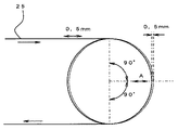
体積抵抗率や表面抵抗率については、高抵抗抵抗率計(三菱化学社製:ハイレスタIP)で測定することが可能である。計測器本体にHRSプローブ(内側電極直径5.9mm、リング電極内径11mm)を接続し、中間転写ベルト25の表裏に所定の電圧(体積抵抗率測定時には100V、表面抵抗率測定時には500V)の電圧を印加して、10秒後の値を測定結果として採用する。
The volume resistivity and surface resistivity can be measured with a high resistivity meter (manufactured by Mitsubishi Chemical Corporation: Hiresta IP). An HRS probe (inner electrode diameter 5.9 mm, ring electrode
中間転写ベルト25の表面には、必要に応じて、離型促進層をコートしても良い。離型促進層の材料としては、ETFE(エチレン−四フッ化エチレン共重合体)、 PTFE(ポリ四フッ化エチレン)、PVDF(フッ化ビニルデン)、PEA(パ−フルオロアルコキシフッ素樹脂)、FEP(四フッ化エチレン−六フッ化プロピレン共重合体)、PVF(フッ化ビニル)等のフッ素樹脂を例示することができる。
A release promoting layer may be coated on the surface of the
1次転写ローラ26K,Y,M,Cは、鉄、ステンレス、アルミニウム等からなる芯金の表面に発泡樹脂からなる弾性層を被覆したものである。弾性層の厚みは2〜10[mm]であるが、この範囲に限定されるものではない。
The
定着装置34に搬送された記録シートは、定着装置34内における加圧や加熱によってフルカラー画像が定着させしめられた後、定着装置34から排紙ローラ対35に送られた後、機外へと排出される。
The recording sheet conveyed to the fixing
先に示した図1において、紙搬送ユニット22および定着装置34の下には、スイッチバック装置36が配設されている。これにより、片面に対する画像定着処理を終えた記録シートが、切換爪で記録シートの進路を記録シート反転装置側に切り換えられ、そこで反転されて再び2次転写転写ニップに進入する。そして、もう片面にも画像の2次転写処理と定着処理とが施された後、排紙トレイ上に排紙される。
In FIG. 1 described above, a
画像形成部1にセットするトナーとしては、形状係数SF−1が100〜180であって、且つ形状係数SF−2が100〜180であるものを用いている。図5は、形状係数SF−1を説明するための模式図である。形状係数SF−1は、トナー形状の丸さの割合を示す指標値であり、「SF−1={(MXLNG)2/AREA}×(100π/4)」という数式によって求められる。トナーを2次元平面に投影してできる形状の最大長MXLNGの二乗を図形面積AREAで除して、100π/4を乗じた値である。形状係数SF−1の値が100であるトナーの形状は真球であり、SF−1の値が大きくなるほど球形度が悪化する。
As the toner to be set in the
図6は、形状係数SF−2を説明するための模式図である。形状係数SF−2は、トナー形状の凹凸の割合を示す指標値であり、「SF−2={(PERI)2/AREA}×(100π/4)」という数式によって求められる。トナーを2次元平面に投影してできる図形の周長PERIの二乗を図形面積AREAで除して、100π/4を乗じた値である。形状係数SF−2の値が100であるトナーの表面には、凹凸が存在していない。形状係数SF−2の値が大きくなるほど、トナー表面の凹凸が顕著になる。形状係数については、走査型電子顕微鏡(S−800:日立製作所製)でトナーの写真を撮り、これを画像解析装置(LUSEX3:ニレコ社製)に導入して解析することによって求めることが可能である。 FIG. 6 is a schematic diagram for explaining the shape factor SF-2. The shape factor SF-2 is an index value indicating the ratio of the unevenness of the toner shape, and is obtained by an equation “SF-2 = {(PERI) 2 / AREA} × (100π / 4)”. A value obtained by dividing the square of the perimeter PERI of the figure formed by projecting the toner on the two-dimensional plane by the figure area AREA and multiplying by 100π / 4. There is no unevenness on the surface of the toner having a shape factor SF-2 value of 100. As the shape factor SF-2 increases, the unevenness of the toner surface becomes more prominent. The shape factor can be obtained by taking a photograph of the toner with a scanning electron microscope (S-800: manufactured by Hitachi, Ltd.), introducing it into an image analyzer (LUSEX 3: manufactured by Nireco) and analyzing it. is there.
トナーの形状が球形に近くなると、トナーとトナーあるいはトナーと感光体との接触状態が点接触になるために、トナー同士の吸着力は弱くなり従って流動性が高くなり、また、トナーと感光体との吸着力も弱くなって、転写率は高くなる。形状係数SF−1、形状係数SF−2の何れかが180を超えると、転写率が低下するとともに転写手段に付着した場合のクリーニング性も低下するため好ましくない。また、トナー粒径は体積平均粒径で4〜10[μm]の範囲であることが望ましい。これよりも小粒径の場合には現像時に地汚れの原因になったり、流動性が悪化し、さらに凝集しやすくなるので中抜けが発生しやすくなる。逆にこれよりも大粒径の場合にはトナー飛び散りや、解像度悪化により高精細な画像を得ることができない。実施形態に係る複写機では、体積平均粒径が6.5[μm]であるトナーをセットしている。 When the shape of the toner is close to a spherical shape, the contact state between the toner and the toner or the toner and the photoconductor becomes a point contact, so that the adsorbing force between the toners becomes weak and the fluidity increases, and the toner and the photoconductor The attraction force becomes weaker and the transfer rate becomes higher. If either of the shape factor SF-1 or the shape factor SF-2 exceeds 180, the transfer rate is lowered and the cleaning property when attached to the transfer unit is also not preferred. The toner particle size is preferably in the range of 4 to 10 [μm] in terms of volume average particle size. When the particle size is smaller than this, it becomes a cause of background stains during development, fluidity is deteriorated, and the particles are more likely to be aggregated. On the other hand, when the particle size is larger than this, it is impossible to obtain a high-definition image due to toner scattering or resolution deterioration. In the copying machine according to the embodiment, a toner having a volume average particle diameter of 6.5 [μm] is set.
図1において、画像形成部1の上に固定されたスキャナ150やこれの上に固定されたADF51は、固定読取部や移動読取部152を有している。移動読取部152は、原稿MSに接触するようにスキャナ150のケーシング上壁に固定された図示しない第2コンタクトガラスの直下に配設されており、光源や、反射ミラーなどからなる光学系を図中左右方向に移動させることができる。そして、光学系を図中左側から右側に移動させていく過程で、光源から発した光を第2コンタクトガラス上に載置された図示しない原稿で反射させた後、複数の反射ミラーを経由させて、スキャナ本体に固定された画像読取センサー153で受光する。
In FIG. 1, a
一方、固定読取部は、スキャナ150の内部に配設された第1面固定読取部151と、ADF51内に配設された図示しない第2面固定読取部とを有している。光源、反射ミラー、CCD等の画像読取センサーなどを有する第1面固定読取部151は、原稿MSに接触するようにスキャナ150のケーシング上壁に固定された図示しない第1コンタクトガラスの直下に配設されている。そして、後述するADF51によって搬送される原稿MSが第1コンタクトガラス上を通過する際に、光源から発した光を原稿面で順次反射させながら、複数の反射ミラーを経由させて画像読取センサーで受光する。これにより、光源や反射ミラー等からなる光学系を移動させることなく、原稿MSの第1面を走査する。また、第2面固定読取部は、第1面固定読取部151を通過した後の原稿MSの第2面を走査する。
On the other hand, the fixed reading unit includes a first surface fixed
スキャナ150の上に配設されたADF51は、本体カバー52に、読取前の原稿MSを載置するための原稿載置台53、シート部材としての原稿MSを搬送するための搬送ユニット54、読取後の原稿MSをスタックするための原稿スタック台55などを保持している。図4に示すように、スキャナ150に固定された蝶番159によって上下方向に揺動可能に支持されている。そして、その揺動によって開閉扉のような動きをとり、開かれた状態でスキャナ150の上面の第1コンタクトガラス154や第2コンタクトガラス155を露出させる。原稿束の片隅を綴じた本などの片綴じ原稿の場合には、原稿を1枚ずつ分離することができないため、ADFによる搬送を行うことができない。そこで、片綴じ原稿の場合には、ADF51を図4に示すように開いた後、読み取らせたいページが見開かれた片綴じ原稿を下向きにして第2コンタクトガラス154上に載せた後、ADFを閉じる。そして、スキャナ150の図1に示した移動読取部152によってそのページの画像を読み取らせる。
An
一方、互いに独立した複数の原稿MSを単に積み重ねた原稿束の場合には、その原稿MSをADF51によって1枚ずつ自動搬送しながら、スキャナ150内の第1面固定読取部151やADF51内の第2面固定読取部に順次読み取らせていくことができる。この場合、原稿束を原稿載置台53上にセットした後、図示しないコピースタートボタンを押す。すると、ADF51が、原稿載置台53上に載置された原稿束の原稿MSを上から順に搬送ユニット54内に送り、それを反転させながら原稿スタック台55に向けて搬送する。この搬送の過程で、原稿MSを反転させた直後にスキャナ150の第1面固定読取部151の真上に通す。このとき、原稿MSの第1面の画像がスキャナ150の第1面固定読取部151によって読み取られる。
On the other hand, in the case of a document bundle in which a plurality of document MSs independent from each other are simply stacked, the document MS is automatically conveyed one by one by the
次に、転写装置としての転写ユニット24について詳述する。
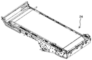
図7は、転写ユニット24を示す斜視図である。転写ユニット24は、図示のような状態で複写機本体に対して着脱される。転写ユニット24において、複数のローラを架け渡している2枚の側板のうち、前側板には、図8に示されるように、駆動モータ203やエンコーダ202が固定されている。駆動モータ203は、中間転写ベルト25を掛け回している駆動ローラ27cの駆動源になっているモータである。また、エンコーダ202は、駆動ローラ27cの回転速度を検知するものであり、第2速度検知手段として機能している。
Next, the
FIG. 7 is a perspective view showing the
図9は、2つの側板を取り外した状態の転写ユニット24を制御装置201とともに示す斜視図である。転写ユニット24は、中間転写ベルト25を駆動するためのベルト駆動装置を有している。このベルト駆動装置は、中間転写ベルト、中間転写ベルト25をループ内側で支持しながら張架する複数の張架ローラ、制御装置201、駆動モータ203、減速機204、スケールセンサー205等を具備している。
FIG. 9 is a perspective view showing the
複数の張架ローラの1つである駆動ローラ27cには、減速機204を介して駆動モータ203の駆動力が伝達される。これにより、駆動ローラ27cが回転すると、それに追従して中間転写ベルト25が図中時計回り方向に無端移動する。駆動ローラ27cとしては、芯金の表面にゴム層が被覆されたゴムローラからなるものを用いている。芯金としては、押し出し成型されたアルミ製のものを用いているが、金属であれば、アルミ以外の材料からなるものを用いても良い。芯金の上に被覆されたゴム層は、EPゴムからなり、0.5[mm]の厚みで芯金上に被覆されている。
The driving force of the driving
中間転写ベルト25に対して1[N/cm]以上の張力を付与する場合には、駆動ローラ27cの直径を16[mm]以上にすることが望ましい。中間転写ベルト25として、PI材からなるものを用いると、ローラの周面に巻き付いた状態で長時間放置されることによる巻き付き癖が発生し易くなるが、直径16[mm]以上であれば、巻き付き癖の発生が抑えられるからである。待機時に中間転写ベルト25のテンションを緩める構成を付加している場合には、駆動ローラ27cの直径を16[mm]にしてもよい。
When a tension of 1 [N / cm] or more is applied to the
中間転写ベルト25の幅方向の一端部には、ベルト全周に渡って所定のピッチで並ぶ複数のスケールマークを具備するスケール209が設けられている。同図においては、スケール209をベルトおもて面(ループ外周面)に設けた例を示しているが、ベルト裏面(ループ内周面)に設けてもよい。スケール209は、ベルト表面よりも反射率の高い材料、あるいは反射率の低い材料からなるテープに、スケールマークが印刷されたものであり、ベルト全周に渡って延在するように貼り付けられている。
At one end in the width direction of the
第1速度検知手段としてのスケールセンサー205は、反射型フォトセンサーからなり、発光素子から発した光をスケール209のスケールマーク表面で反射させ、得られた反射光を受光素子で検知する。そして、受光量に応じた検知信号を制御装置201に出力する。
The
図10は、スケールセンサー205と、スケール209の各スケールマークSMとを示す模式図である。複数のスケールマークSMは、光反射性を有する材料からなり、ベルト移動方向に沿って所定のピッチP0で並んでいる。スケール209における何れかのスケールマークSMがスケールセンサー205の直下に移動してくると、スケールセンサー205の発光素子から発せられた光がそのスケールマークSMの表面で反射し、得られた反射光がスケールセンサー205の受光素子に受光される。
FIG. 10 is a schematic diagram showing the
制御装置(図9の201)は、スケールセンサー205によって個々のスケールマークSMを検知する時間間隔を所定の周期にするように、駆動モータ(図9の203)の駆動速度を制御することで、中間転写ベルト(25)を目標の速度で走行させる。
The control device (201 in FIG. 9) controls the drive speed of the drive motor (203 in FIG. 9) so that the time interval at which each scale mark SM is detected by the
図11は、転写ユニット(24)の電気回路の要部を示すブロック図である。制御装置201は、中間転写ベルト25の駆動源である駆動モータ203を駆動する方式として、正常時用駆動方式と、異常時駆動方式とを繰り替えて実施する。正常時駆動方式では、スケールセンサー205によってスケール209の各スケールマークを検知する周期、即ち、ベルト移動速度を検知した結果に基づいて、駆動モータ203の駆動速度を調整する。また、異常時駆動方式では、駆動ローラ27cの軸に固定されたエンコーダ202によって駆動ローラ27cの回転速度を検知した結果に基づいて、駆動モータ203の駆動速度を調整する。
FIG. 11 is a block diagram showing the main part of the electric circuit of the transfer unit (24). The
図12は、転写ユニット(24)における電気回路を図11よりも詳細に示すブロック図である。制御装置201は、第1速度値変換部201a、第1演算器201b、目標速度設定部201c、コントローラ201d、第2速度値変換部201e、第2演算器201f、スイッチング回路201g、異常判定部201hなどを具備している。スケールセンサー205からの出力信号は、制御装置201の第1速度値変換部201a、目標速度設定部201c、異常判定部201hにそれぞれ入力される。
FIG. 12 is a block diagram showing the electric circuit in the transfer unit (24) in more detail than FIG. The
スケールセンサー205からの出力信号はアナログ電圧信号であり、その波形は立ち上がり部と立ち下がり部とが交互に繰り返される形状になる。立ち上がり部は、スケールマーク上で得られた反射光を受光素子によって受光しているときのスケールセンサー205から出力されるものである。つまり、マーク検知信号である。これに対し、立ち下がり部は、スケールマーク上で得られた反射光を受光素子によって受光していないときのスケールセンサー205から出力されるものである。つまり、マーク非検知信号である。
The output signal from the
第1速度値変換部201aは、スケールセンサー205からの出力信号におけるパルス立ち上がりが発生する周期、即ち、スケールセンサー205がスケールマークSMを検知する周期、に基づいて、中間転写ベルトの移動速度を算出し、その結果であるベルト速度測定値をデジタル信号で第1演算器201bに出力する。また、目標速度設定部201cは、中間転写ベルトの目標速度をデジタル信号で第1演算器201bに出力する。第1演算器201bは、第1速度値変換部201aから出力されるベルト速度測定値と、目標速度設定部201cから出力される目標速度との差分を演算して、その結果であるベルト速度差をスイッチング回路201gに出力する。
The first speed value conversion unit 201a calculates the moving speed of the intermediate transfer belt based on the period in which the pulse rising in the output signal from the
一方、第2速度値変換部201eは、エンコーダ202からの出力信号におけるパルス立ち上がりが発生する周期、即ち、エンコーダースケールのスケールマークが検知される周期、に基づいて、駆動ローラ27cの回転速度を算出し、その結果であるローラ回転速度測定値をデジタル信号で第2演算器201fに出力する。また、目標速度設定部201cは、駆動ローラ27cの目標回転速度をデジタル信号で第2演算器201fに出力する。第2演算器201fは、第2速度値変換部201eから出力されるローラ回転速度測定値と、目標速度設定部201cから出力される目標回転速度との差分を演算して、その結果である回転速度差をスイッチング回路201gに出力する。
On the other hand, the second speed value conversion unit 201e calculates the rotation speed of the
また、異常判定部201hは、スケールセンサー205からの出力信号におけるパルス立ち下がり周期の変化状況に基づいて、スケールマークSMの異常(以下、スケール異常という)の有無を判定する。具体的には、トナー等の汚れの付着によって光反射性を著しく低下させてしまったスケールマークSMが発生し、そのスケールマークSMがスケールセンサー205によって検知されなくなったとする。すると、そのスケールマークSMがベルトの移動に伴ってスケールセンサー205の直下を通過する前後では、パルス立ち上がり周期が約2倍になる。より詳しくは、例えば、中間転写ベルトが目標速度の付近で走行しているときに、スケールセンサー205からの出力信号のパルス立ち上がり周期が基準クロック周期の14倍程度になるとする。このような状態で、光反射性を著しく低下させたスケールマークSM(以下、異常マークという)がスケールセンサー205の直下を通過する際には、そのときだけパルス立ち上がり周期が基準クロック周期の28倍程度まで急激に上昇する。異常判定部201hは、このようにパルス立ち下がり周期が急上昇した場合に、その次のパルス立ち下がり周期と、1つ前のパルス立ち下がり周期とを比較する。中間転写ベルトの移動速度が何らかの突発的な理由によって急上昇した場合、異常マークが発生していなくても、パルス立ち下がり周期が急上昇する。但し、この場合、パルス立ち下がり周期が一瞬だけ急上昇するのではなく、上昇した状態がある程度持続することになる。このため、次の立ち下がり周期も、1つ前の立ち下がり周期に比べて大幅に大きくなる。このような場合、異常判定部201hは、マーク異常は発生していないと判定する。一方、パルス立ち下がり周期の急上昇が異常マークによるものである場合、次のパルス立ち下がり周期は、正常な周期に戻る。このため、次のパルス立ち下がり周期と、1つ前の立ち下がり周期との差は、所定の閾値内に収まる。この場合、異常判定部201hは、異常マークが発生したと判定する。
Further, the
図13は、制御装置201によって実施される制御の処理フローを示すフローチャートである。制御装置201は、所定の開始タイミングが到来すると(ステップ1でY:以下、ステップをSと記す)、マーク異常フラグについて、セット中であるか否かを判定する。そして、セット中でない場合には(S2でN)、スケールセンサーからの出力信号に基づいて駆動モータの駆動速度を調整する正常時駆動方式で、駆動モータの駆動を開始する(S3)。正常時駆動方式では、スケールセンサーからの出力信号に基づいて、駆動モータの駆動速度をフィードバック制御しながら(S4)、マーク異常の有無を判定する。そして、マーク異常が認められた場合には(S5でY)、マーク異常フラグをセットした後(S6)、駆動モータの駆動制御方式を正常時駆動方式から異常時駆動方式に切り替える(S7)。また、マーク異常が認められない場合には(S5でN)、正常駆動方式での駆動モータの駆動制御を継続する。その後、所定の停止タイミングが到来すると(S8でY)、駆動モータの駆動を停止させる(S9)。
FIG. 13 is a flowchart illustrating a control processing flow executed by the
一方、S2の工程において、マーク異常フラグについてセット中であると判定すると(S2でY)、エンコーダからの出力信号に基づいて駆動モータの駆動速度を調整する異常時駆動方式で、駆動モータの駆動を開始する(S10)。異常時駆動方式では、エンコーダからの出力信号に基づいて、駆動モータの駆動速度をフィードバック制御する(S11)。そして、所定の停止タイミングが到来すると(S12でY)、駆動モータの駆動を停止させる(S9)。 On the other hand, if it is determined in step S2 that the mark abnormality flag is being set (Y in S2), the driving motor is driven by the abnormal time driving method in which the driving speed of the driving motor is adjusted based on the output signal from the encoder. Is started (S10). In the abnormal driving method, the drive speed of the drive motor is feedback-controlled based on the output signal from the encoder (S11). When a predetermined stop timing arrives (Y in S12), the drive motor is stopped (S9).
次に、本発明者らが行った実験について説明する。
本発明者らは、実施形態に係る複写機の基本構成と同様の基本構成を有する試験機を用意した。そして、この試験機の中間転写ベルトの駆動モータを正常時駆動方式で駆動しながら、制御装置に対して、スケールセンサーからの出力信号に基づいて算出した個々のベルト速度測定値をデータ記憶回路に順次記憶させていく処理を実施させた。
Next, experiments conducted by the present inventors will be described.
The inventors prepared a test machine having a basic configuration similar to the basic configuration of the copying machine according to the embodiment. Then, while driving the driving motor of the intermediate transfer belt of this testing machine in the normal driving method, the individual belt speed measurement values calculated based on the output signal from the scale sensor are stored in the data storage circuit to the control device. A process of sequentially storing them was performed.
図14は、この実験で得られたベルト速度測定値の経時変化を示すグラフである。中間転写ベルトに付すスケールとしては、スケールマークSMを0.1[mm]のピッチで並べたものを採用した。このスケールにおけるスケールマークSMのピッチ誤差は0.1[mm]±0.005[%]である。このため、速度検知誤差(実際の速度と検知速度との差)が0.005[%]を超えることはない。図14に示されるグラフから計算されるベルトの平均速度は、299.875[mm/s]であった。これに対し、目標速度については、299.86[mm/s]に設定していた。299.875[mm/s]という数値は、目標速度に対して−0.0005[%]の誤差を発生させた数値であり、目標速度±0.005[%]の範囲内に収まっているので、ベルト速度を高い精度で制御できていることがわかる。 FIG. 14 is a graph showing the change with time in the measured belt speed obtained in this experiment. As the scale attached to the intermediate transfer belt, a scale in which scale marks SM are arranged at a pitch of 0.1 [mm] was used. The pitch error of the scale mark SM in this scale is 0.1 [mm] ± 0.005 [%]. For this reason, the speed detection error (the difference between the actual speed and the detected speed) does not exceed 0.005 [%]. The average belt speed calculated from the graph shown in FIG. 14 was 299.875 [mm / s]. On the other hand, the target speed was set to 299.86 [mm / s]. The numerical value of 29.875 [mm / s] is a numerical value in which an error of −0.0005 [%] is generated with respect to the target speed, and is within the range of the target speed ± 0.005 [%]. Therefore, it can be seen that the belt speed can be controlled with high accuracy.
次に、本発明者らは、駆動モータの駆動制御方式を正常時駆動方式から異常時駆動方式に代えて、同様の実験を行った。図15は、この実験で得られたベルト速度測定値の経時変化を示すグラフである。このグラフから計算されるベルトの平均速度は、299.5[mm/s]であった。これは、目標である299.86[mm/s]に対して、−0.120[%]の誤差を発生させた数値である。また、先の実験における299.875[mm/s]という平均速度に対して、−0.0125[%]の誤差を発生させた数値である。先の実験と比較すると、誤差が非常に大きくなっていることがわかる。このように誤差が大きくなった原因は、駆動ローラの径の公差にある。具体的には、駆動ローラとしては、直径=30±0.05[mm]という規格のものを使用している。かかる駆動ローラは、固体毎に29.95〜30.05[mm]の範囲で直径がばらつく。試験機に搭載した駆動ローラの直径は、精密測定器で測定したところ、29.964[mm]であった。これは、目標の直径に対して−0.12[%]の誤差を発生させた数値である。そして、この数値は、目標速度に対する平均速度の誤差である−0.120[%]という数値と一致している。つまり、駆動ローラの直径の公差が、異常時駆動方式における平均速度の目標速度からの誤差を大きくしているのである。 Next, the present inventors conducted a similar experiment by changing the drive control system of the drive motor from the normal drive system to the abnormal drive system. FIG. 15 is a graph showing the change with time in the measured belt speed obtained in this experiment. The average belt speed calculated from this graph was 299.5 [mm / s]. This is a numerical value in which an error of −0.120 [%] is generated with respect to the target of 299.86 [mm / s]. Moreover, it is a numerical value in which an error of −0.0125 [%] is generated with respect to the average speed of 299.875 [mm / s] in the previous experiment. It can be seen that the error is very large compared to the previous experiment. The cause of the large error is the tolerance of the diameter of the drive roller. Specifically, a drive roller having a diameter of 30 ± 0.05 [mm] is used. Such a driving roller varies in diameter in the range of 29.95 to 30.05 [mm] for each solid. The diameter of the drive roller mounted on the test machine was 29.964 [mm] as measured with a precision measuring instrument. This is a numerical value in which an error of −0.12 [%] is generated with respect to the target diameter. This numerical value coincides with a numerical value of −0.120 [%], which is an error of the average speed with respect to the target speed. In other words, the tolerance of the diameter of the driving roller increases the error from the target speed of the average speed in the abnormal driving method.
このように、異常時駆動方式では、中間転写ベルトの平均速度と目標速度とに比較的大きな誤差を発生させてしまうことから、各色トナー像の重ね合わせズレ量を大きくしてしまう。 As described above, in the abnormal driving method, a relatively large error is generated between the average speed and the target speed of the intermediate transfer belt, so that the amount of misalignment of the color toner images is increased.
次に、実施形態に係る複写機の特徴的な構成について説明する。
図12に示される制御装置201は、プリントジョブを実施していない状態で操作者から目標値補正動作命令がなされると、目標値補正処理を実施する。但し、上述したマーク異常フラグがセットされている状態では、目標値補正動作命令がなされても、目標値補正処理を実施しない。なお、セット中のマーク異常フラグについては、中間転写ベルトを交換又は清掃した操作者から、マーク異常解消情報が入力されたことに基づいて、セットを解除する。
Next, a characteristic configuration of the copier according to the embodiment will be described.
The
目標値補正処理では、まず、駆動モータの駆動を異常時駆動方式で開始する。以下、異常時駆動方式におけるベルトの目標速度を目標速度Vsという。また、正常時駆動方式における駆動ローラの目標回転速度を目標回転速度ωsという。また、目標速度Vsが299.86[mm/s]であり、目標回転速度ωsの初期値が190.99[rpm]であり、駆動ローラの直径の設計値が30[mm]であり、駆動ローラの実際の直径が29.964[mm]である場合を例にして、目標値補正処理を説明する。 In the target value correction process, first, driving of the drive motor is started by the abnormal time driving method. Hereinafter, the target speed of the belt in the abnormal driving method is referred to as a target speed Vs. The target rotational speed of the driving roller in the normal driving method is referred to as target rotational speed ωs. The target speed Vs is 299.86 [mm / s], the initial value of the target rotational speed ωs is 190.99 [rpm], the design value of the diameter of the drive roller is 30 [mm], and the drive The target value correction process will be described by taking as an example a case where the actual diameter of the roller is 29.964 [mm].
異常時駆動方式では、駆動ローラの直径に公差が全くなければ、中間転写ベルトの平均速度が目標速度Vs(299.86mm/s)とほぼ同じになる。但し、駆動ローラの直径に公差があると、その公差に応じた量だけ、中間転写ベルトの平均速度が目標速度Vsからずれることになる。そこで、制御装置201のコントローラ201dは、少なくとも中間転写ベルトを1周以上させる期間に渡って、駆動モータを異常時駆動方式で駆動する。制御装置201の目標速度設定部201cは、その期間において、スケールセンサー205からの出力信号に基づいて、ベルト速度測定値を所定の周期毎に算出し、結果をデータ記憶回路に記憶させる。そして、駆動モータの駆動が停止されると、データ記憶回路に記憶させた複数のベルト速度測定に基づいて、中間転写ベルトの平均速度Vaveを算出する。次いで、算出結果で正常時目標速度Vnを除算する(Vs/Vave)。その結果は、駆動ローラの径の公差に応じたベルト平均速度の目標速度Vsからのずれ量を反映している。目標速度設定部201cは、その結果の乗算により、目標回転速度ωsを補正する(ωs=ωs×Vs/Vave)。これにより、目標回転速度ωsが、駆動ローラの径の公差に応じた値に補正される。
In the abnormal driving method, if there is no tolerance in the diameter of the driving roller, the average speed of the intermediate transfer belt is almost the same as the target speed Vs (299.86 mm / s). However, if there is a tolerance in the diameter of the drive roller, the average speed of the intermediate transfer belt deviates from the target speed Vs by an amount corresponding to the tolerance. Therefore, the
より詳しくは、駆動ローラの直径の設計値が30[mm]である。駆動ローラの直径に公差がない場合、駆動ローラを目標回転速度ωsの初期値である190.93[rpm]で回転させると、駆動ローラの線速は約299.86[mm/s]になって(30×3.141×190.93/60)、目標速度Vsと一致する。しかし、実際の直径は29.964[mm]であるので、駆動ローラを目標回転速度ωsの初期値である190.93[rpm]で回転させると、駆動ローラの線速は299.5[mm/s]になって(29.961×3.141×190.93/60)、目標速度Vsと一致しなくなる。但し、その線速は、平均速度Vaveとして検知することができる。つまり、平均速度Vaveが299.5[mm/s]になる。目標速度Vsを平均速度Vaveで除算した結果に目標回転速度ωsの初期値を乗ずると、補正後の目標回転速度ωsは191.17[rpm]になる(299.86/299.5×190.93)。そして、補正後の目標回転速度ωsで駆動ローラを回転させると、その線速は299.87[mm/s]になるので(191.17/60×29.964×3.141)、目標速度Vsとほぼ一致する。 More specifically, the design value of the diameter of the drive roller is 30 [mm]. When there is no tolerance in the diameter of the driving roller, when the driving roller is rotated at 190.93 [rpm] which is the initial value of the target rotational speed ωs, the linear speed of the driving roller becomes about 299.86 [mm / s]. (30 × 3.141 × 190.93 / 60), which matches the target speed Vs. However, since the actual diameter is 29.964 [mm], when the driving roller is rotated at 190.93 [rpm] which is the initial value of the target rotational speed ωs, the linear speed of the driving roller is 299.5 [mm]. / S] (29.961 × 3.141 × 190.93 / 60), the speed does not coincide with the target speed Vs. However, the linear velocity can be detected as the average velocity Vave. That is, the average speed Vave is 299.5 [mm / s]. When the result of dividing the target speed Vs by the average speed Vave is multiplied by the initial value of the target rotational speed ωs, the corrected target rotational speed ωs becomes 191.17 [rpm] (299.86 / 299.5 × 190. 93). When the drive roller is rotated at the corrected target rotational speed ωs, the linear speed becomes 299.87 [mm / s] (191.17 / 60 × 29.964 × 3.141), so the target speed It almost coincides with Vs.
このように、本複写機においては、異常時駆動方式で第2算出値としてのローラ回転速度測定値を、第2目標値としての目標回転速度ωsと同じにするように駆動モータの駆動速度を制御すると、駆動ローラの径の加工誤差(公差)に起因して、中間転写ベルトが目標速度Vsからずれた速度で移動する。そのずれ量を、第1算出値としての平均速度Vaveと、第1目標値たる目標速度Vsとの差に基づいて把握する。そして、把握結果に基づいて、第1算出値たる平均速度Vaveを、第1目標値たる目標速度Vsと同等にするように、第2目標値たる目標回転速度ωsを補正する。これにより、目標回転速度ωs、実際の駆動ローラの径に見合った値にすることで、異常時駆動方式において、駆動ローラの径の加工誤差に起因する平均速度Vaveの目標速度Vsからのずれを低減することができる。 Thus, in this copying machine, the drive speed of the drive motor is set so that the measured value of the roller rotational speed as the second calculated value is the same as the target rotational speed ωs as the second target value in the abnormal driving method. When controlled, the intermediate transfer belt moves at a speed deviating from the target speed Vs due to a processing error (tolerance) of the diameter of the drive roller. The amount of deviation is grasped based on the difference between the average speed Vave as the first calculated value and the target speed Vs as the first target value. Based on the grasped result, the target rotational speed ωs as the second target value is corrected so that the average speed Vave as the first calculated value is equal to the target speed Vs as the first target value. Thus, by setting the target rotational speed ωs to a value commensurate with the actual driving roller diameter, in the abnormal driving method, the deviation of the average speed Vave from the target speed Vs due to the processing error of the driving roller diameter is reduced. Can be reduced.
なお、初回の目標値補正処理については、工場出荷時に行ってもよいし、ユーザーのもとにおける初期運転実施に自動で行うようにしてもよい。駆動ローラの交換作業を行った場合には、交換作業者が目標値補正動作命令を操作表示部に対する操作によって行うことで、目標値補正処理を行わせて異常時目標速度Vaを交換後のローラ径に見合ったものにする。補正を行うのはあくまでも異常時目標速度Vaだけであって、正常時目標速度Vnについては、初期値のまま維持する。 Note that the initial target value correction processing may be performed at the time of shipment from the factory, or may be automatically performed when the initial operation is performed under the user. When the replacement operation of the driving roller is performed, the replacement operator performs a target value correction operation command by operating the operation display unit, thereby performing target value correction processing and replacing the abnormal target speed Va after replacement. Make it suitable for the diameter. Only the abnormal target speed Va is corrected, and the normal target speed Vn is maintained at the initial value.
また、正常時駆動方式において、第1算出値たるベルト速度測定値と、第1目標値たる目標速度Vsとの比較に基づいて駆動モータの駆動速度を調整する例について説明したが、第1検知結果であるスケール検知信号の立ち上がり周期と、第1目標値である目標周期とに基づいて駆動モータの駆動速度を調整してもよい。この場合、目標値補正処理において、目標周期を立ち上がり周期測定値で除算した結果の乗算によって第2検知結果又は第2算出値を補正すればよい。 In the normal driving method, the example in which the drive speed of the drive motor is adjusted based on the comparison between the measured belt speed value that is the first calculated value and the target speed Vs that is the first target value has been described. The drive speed of the drive motor may be adjusted based on the rise period of the scale detection signal that is the result and the target period that is the first target value. In this case, in the target value correction process, the second detection result or the second calculated value may be corrected by multiplying the result obtained by dividing the target period by the rising period measurement value.
また、異常時駆動方式において、第2算出値たるローラ回転速度測定値と、第2目標値たる目標回転速度ωsとの比較に基づいて駆動モータの駆動速度を調整する例について説明したが、第2検知結果であるエンコーダ検知信号の立ち上がり周期と、第2目標値である目標周期とに基づいて駆動モータの駆動速度を調整してもよい。 In the abnormal driving method, the example in which the drive speed of the drive motor is adjusted based on the comparison between the measured value of the roller rotational speed as the second calculated value and the target rotational speed ωs as the second target value has been described. The drive speed of the drive motor may be adjusted based on the rising period of the encoder detection signal that is the second detection result and the target period that is the second target value.
また、第2速度検知手段として、駆動ローラ27cの回転速度を検知するエンコーダ202を設けた例について説明したが、駆動モータ203の回転速度を検知するものを設けたもよい。例えば、DCブラシレスモータには、モータ回転速度を表すFG信号を発生するFG信号発電機を内蔵するものがある。そのFG信号発電機を第2速度検知手段として用いてもよい。
Moreover, although the example which provided the
図16は、転写ユニット24を側方から示す概略構成図である。同図において、1次転写ローラ26K,Y,M,Cは、次のような条件を具備するように配設されている。即ち、ベルト移動方向の最上流側に配設された1次転写ローラ26Kの位置から、最下流側に配設された1次転写ローラ26Cの位置に向けて、中間転写ベルト25を直線的に移動させるという条件である。かかる条件を具備するために、1次転写ローラ26K,Y,M,Cは、互いに同じ巻き付き角度で中間転写ベルト25を巻き付けており、且つ、その巻き付き角度は比較的小さな値になっている。より詳しくは、巻き付き角度は8.13[°]になっている。なお、巻き付き角は、ローラ表面の周方向におけるベルト接触開始点とローラ中心点とを結ぶ線分と、ローラ表面の周方向におけるベルト離間開始点とローラ中心点とを結ぶ線分とのなす角度である。
FIG. 16 is a schematic configuration diagram showing the
中間転写ベルト25のループ内側に配設された複数の張架ローラのうち、いくつかは、ベルト移動方向を大きく転換させるために、自らの表面に対して大きな巻き付き角度で中間転写ベルト25を巻き付ける方向転換ローラとして機能している。具体的には、下部張架ローラ27a、駆動ローラ27c、テンションローラ27bなどが方向転換ローラとして機能している。
Among a plurality of stretching rollers disposed inside the loop of the
最下流側の1次転写ローラ26Cに対する掛け回し位置を通過した中間転写ベルト25は、やがて方向転換ローラによって方向転換せしめられる。その役割をになっているのが、駆動ローラ27cである。
The
本複写機においては、図示のように、第1速度検知手段たるスケールセンサー205を、最上流側の1次転写ローラ26Kよりもベルト移動方向の下流側であって、最下流側の1次転写ローラ26Cよりもベルト移動方向の上流側の位置に配設している。この位置では、上述したように、中間転写ベルト25がほぼ直線的に移動する。そして、その付近では、複数の1次転写ニップが形成される。複数の1次転写ニップが形成される位置の付近で中間転写ベルト25の速度をスケールセンサー205によって検知してその結果を駆動モータの駆動制御にフィードバックすることで、1次転写ニップにおけるベルト速度変動を抑えることができる。
In this copying machine, as shown in the figure, the
また、本複写機においては、最下流側の1次転写ローラ27cに対するベルトの巻き付き角度を他の1次転写ローラに対するベルト巻き付き角度と同じにすることで、1次転写ローラ26Cを方向転換ローラとして機能させていない。かかる構成では、1次転写ローラ26Cを方向転換ローラとして機能させる場合に比べて、方向転換ローラの振れに起因する重ね合わせずれを抑えることができる。具体的には、方向転換ローラは、中間転写ベルト25を大きな巻き付き角度で巻き付けるものであるため、ベルトテンションによる力が強くかかって振れやすくなる。そして、巻き付き角度が大きくなるほど、方向転換ローラの振れに伴うベルト速度変動が大きくなる。
In this copying machine, the
図17は、方向転換ローラの振れに起因するベルト速度変動を説明するための拡大構成図である。図示の方向転換ローラに対しては、中間転写ベルト25が180[°]の巻き付き角度で巻き付いている。方向転換ローラは、巻き付き角度の中心の位置で振れるときに、中間転写ベルト25の速度変動を最も大きくする。図示の例では、矢印A方向の振れである。この矢印A方向に方向転換ローラが0.5[mm]の振れ幅で振れると、方向転換ローラの近傍で且つ方向転換ローラよりも上流側のベルト箇所も、それに追従して0.5[mm]の変動幅で変位を起こす。当然ながら、変位量が大きくなるほど、ベルトの速度を大きく変化させてしまう。
FIG. 17 is an enlarged configuration diagram for explaining the belt speed fluctuation caused by the deflection of the direction changing roller. The
図18は、1次転写ローラ26Cの振れに起因するベルト速度変動を説明するための拡大構成図である。中間転写ベルト25は、8.13[°]という非常に小さな巻き付き角度で1次転写ローラ26Cに巻き付いている。このため、1次転写ローラ26Cは、方向転換ローラとしては機能していない。図示の構成においては、1次転写ローラ26Cが矢印Bの方向に振れた場合に、振れに起因するベルト速度変動が最も大きくなる。1次転写ローラ26Cが矢印Bの方向に0.5[mm]の振れ幅で振れた場合、ローラよりも下流側のベルト箇所はその振れに伴って0.1138[mm]しか変位しない。0.5[mm]も変位してしまう図17の構成に比べると、ベルト速度変動量が格段に小さくなる。
FIG. 18 is an enlarged configuration diagram for explaining the belt speed fluctuation caused by the shake of the
本複写機においては、最下流側の1次転写ローラ26Cを方向転換ローラとして機能させず、それよりもベルト移動方向下流側に方向転換ローラとしての駆動ローラ27cを配設することで、1次転写ローラ26Cを方向転換ローラとして機能させる場合に比べて、駆動ローラ27cの振れに起因する中間転写ベルト25の1次転写面(K用の1次転写ニップからC用の1次転写ニップに至るまでの面)の速度変動を抑える。これにより、1次転写面の速度変動に起因する重ね合わせずれを抑えることができる。
In this copying machine, the
図19は、変形例に係る複写機の要部構成を示す要部構成図である。この複写機においては、第1速度検知手段として、スケールセンサーの代わりに、従動エンコーダー208を設けている。この従動エンコーダー208は、中間転写ベルト25の無端移動に伴って従動回転するテンションローラ27bの回転速度を検知する。テンションローラ27bの線速は、中間転写ベルト25の線速と同じであるので、テンションローラ27bの回転速度を検知することで、中間転写ベルト25の移動速度を求めることができる。
FIG. 19 is a main part configuration diagram showing a main part configuration of a copying machine according to a modification. In this copying machine, a driven
以上に説明したものは一例であり、本発明は、次の態様毎に特有の効果を奏する。
[態様A]
無端状のベルト部材(例えば中間転写ベルト25)と、前記ベルト部材のループ内側で前記ベルト部材を支持しながら張架する複数の張架部材と、複数の張架部材の1つであり、自らの回転駆動に伴って前記ベルト部材を無端移動させる駆動ローラ(例えば27c)と、前記ベルト部材の表面移動速度、又は前記ベルト部材の無端移動に追従する従動部材の速度を検知する第1速度検知手段(例えばスケールセンサー205)と、前記駆動ローラの回転速度、又は前記駆動ローラの駆動源である駆動モータ(例えば203)の回転速度を検知する第2速度検知手段(例えばエンコーダ202)と、前記第1速度検知手段や前記第2速度検知手段による検知結果に基づいて、前記駆動モータの駆動速度を制御して前記ベルト部材の移動速度を調整する制御手段(例えば制御装置201)とを備え、前記制御手段が、前記第1速度検知手段による検知結果である第1検知結果について異常なしと判定した場合には、前記第1検知結果、又は、前記第1検知結果に基づく所定の第1算出値と、所定の第1目標値との比較に基づいて前記駆動モータの駆動速度を制御する正常時用駆動方式を採用する一方で、前記第1検知結果について異常ありと判定した場合には、前記第2速度検知手段による検知結果である第2検知結果、又は、前記第2検知結果に基づく所定の第2算出値と、所定の第2目標値との比較に基づいて前記駆動モータの駆動速度を制御する異常時用制御方式を採用するものであるベルト駆動装置において、前記第1検知結果に異常がない状態で、前記第2検知結果又は前記第2算出値と前記第2目標値との比較に基づいて前記駆動モータの駆動速度を制御しながら、前記第1検知結果又は前記第1算出値と前記第1目標値とを比較し、比較結果に基づいて前記第2目標値を補正する目標値補正処理を所定のタイミングで実施するように、前記制御手段を構成したことを特徴とするものである。
What has been described above is merely an example, and the present invention has a specific effect for each of the following modes.
[Aspect A]
An endless belt member (for example, the intermediate transfer belt 25), a plurality of stretching members that support and stretch the belt member inside the loop of the belt member, and one of the plurality of stretching members, First speed detection for detecting a driving roller (e.g., 27c) that moves the belt member endlessly in accordance with the rotational driving of the belt, and a surface moving speed of the belt member or a driven member that follows the endless movement of the belt member. Means (for example, scale sensor 205), second speed detecting means (for example, encoder 202) for detecting the rotational speed of the driving roller, or the rotational speed of a driving motor (for example, 203) that is a driving source of the driving roller, Based on the detection results of the first speed detection means and the second speed detection means, the drive speed of the drive motor is controlled to adjust the moving speed of the belt member. Control means (for example, the control device 201), and when the control means determines that there is no abnormality with respect to the first detection result that is the detection result by the first speed detection means, the first detection result, or While adopting a normal driving method for controlling the driving speed of the driving motor based on a comparison between a predetermined first calculated value based on the first detection result and a predetermined first target value, When it is determined that there is an abnormality in one detection result, a second detection result that is a detection result by the second speed detection means, a predetermined second calculated value based on the second detection result, and a predetermined second In a belt driving apparatus that employs an abnormal time control method for controlling the drive speed of the drive motor based on a comparison with a target value, the second detection result without any abnormality in the first detection result. Or said 2 comparing the first detection result or the first calculated value with the first target value while controlling the driving speed of the drive motor based on the comparison between the calculated value and the second target value. The control means is configured to perform a target value correction process for correcting the second target value based on the above at a predetermined timing.
[態様B]
態様Bは、態様Aにおいて、前記駆動ローラとして、ゴム層が被覆されたゴムローラからなるものを用いたことを特徴とするものである。かかる構成においては、駆動ローラとしてゴムローラではないものを用いる場合に比べて、駆動ローラ表面上でのベルトスリップの発生を抑えて、ベルト部材を安定した速度で駆動することができる。
[Aspect B]
Aspect B is characterized in that, in aspect A, the drive roller is a rubber roller coated with a rubber layer. In such a configuration, it is possible to drive the belt member at a stable speed while suppressing the occurrence of belt slip on the surface of the drive roller as compared with the case where a drive roller that is not a rubber roller is used.
[態様C]
態様Cは、態様A又はBにおいて、前記ベルト部材として、ベルト周方向に所定のピッチで並ぶ複数の目印を具備するスケール(例えば209)を具備するものを用いるとともに、前記第1速度検知手段として、前記目印(例えばスケールマークSM)を検知する目印検知手段(例えばスケールセンサー205)からなるものを用いたことを特徴とするものである。かかる構成では、従動ローラの回転速度に基づいてベルト速度を検知する構成とは異なり、従動ローラの直径に公差があったとしても、その公差が速度検知精度に反映されることがないので、従動ローラの径の公差に起因する速度検知精度の低下を回避することができる。
[Aspect C]
Aspect C uses, in aspect A or B, as the belt member, a belt member having a scale (for example, 209) having a plurality of marks arranged at a predetermined pitch in the belt circumferential direction, and as the first speed detection means. In this embodiment, a mark detecting means (for example, a scale sensor 205) for detecting the mark (for example, the scale mark SM) is used. In such a configuration, unlike the configuration in which the belt speed is detected based on the rotational speed of the driven roller, even if there is a tolerance in the diameter of the driven roller, the tolerance is not reflected in the speed detection accuracy. It is possible to avoid a decrease in speed detection accuracy due to the tolerance of the roller diameter.
[態様D]
態様Dは、態様A又はBにおいて、前記第1速度検知手段として、前記ベルト部材の無端移動に伴って従動回転する前記従動部材としての従動ローラの回転速度を検知する回転速度検知手段(例えば従動エンコーダ208)からなるものを用いたことを特徴とするものである。かかる構成では、スケールセンサーを用いる場合とは異なり、ベルトの伸縮に起因する速度検知精度の低下を回避することができる。
[Aspect D]
Aspect D is a rotation speed detection means (for example, a driven speed) that detects the rotation speed of the driven roller as the driven member that rotates following the endless movement of the belt member as the first speed detection means in aspect A or B. This is characterized in that an encoder 208) is used. In such a configuration, unlike the case of using a scale sensor, it is possible to avoid a decrease in speed detection accuracy due to the expansion and contraction of the belt.
[態様E]
態様Eは、像担持体(例えば感光体4)として、互いに異なる色の可視像を担持する複数の像担持体を設けるとともに、それぞれの像担持体に担持される可視像を前記ベルト部材のおもて面に個別に転写するために、前記ベルト部材の内側におけるぞれぞれの像担持体に対応する位置に配設された複数の転写ローラ(例えば1次転写ローラ26K,Y,M,C)を設け、且つ、前記第1速度検知手段を、最上流側の前記転写ローラ(例えば維持転写ローラ26K)よりもベルト移動方向の下流側であって、最下流側の前記転写ローラ(例えば1次転写ローラ26C)よりもベルト移動方向の上流側の位置に配設したことを特徴とするものである。かかる構成では、複数の1次転写ニップの付近におけるベルト速度変動を検知することで、複数の1次転写ニップの付近でのベルト速度変動を抑えて、重ね合わせずれの発生をより効率的に抑えることができる。
[Aspect E]
In the aspect E, a plurality of image carriers that carry visible images of different colors are provided as the image carrier (for example, the photosensitive member 4), and the visible images carried on the respective image carriers are transferred to the belt member. In order to individually transfer to the front surface, a plurality of transfer rollers (for example,
[態様F]
態様Fは、態様Eにおいて、前記ベルト部材を、ベルト移動方向の最上流側に配設された前記転写ローラの位置から、最下流側に配設された前記転写ローラの位置に向けて前記ベルト部材を直線的に移動させるように、それぞれの前記転写ローラに対して前記ベルト部材を互いに等しい巻き付き角度で巻き付け、且つ、最下流側の前記転写ローラよりも下流側で前記ベルト部材の移動方向を転換させるために、前記ベルト部材を前記巻き付き角度よりも大きな巻き付き角度で自らの周面に巻き付ける方向転換ローラ(例えば駆動ローラ27c)を設けたことを特徴とするものである。かかる構成では、既に説明したように、最下流側の転写ローラを方向転換ローラとして機能させる場合に比べて、ベルト速度変動に起因する重ね合わせずれの発生を抑えることができる。
[Aspect F]
An aspect F is the aspect E in which the belt member is moved from the position of the transfer roller disposed on the most upstream side in the belt moving direction toward the position of the transfer roller disposed on the most downstream side. In order to move the member linearly, the belt member is wound around each transfer roller at the same winding angle, and the moving direction of the belt member is set downstream of the transfer roller on the most downstream side. In order to change the position, a direction changing roller (for example, a driving
4K,Y,C,M:感光体(像担持体)
24:転写ユニット(転写装置)
25:中間転写ベルト(ベルト部材)
26K,Y,C,M:1次転写ローラ(転写ローラ)
27b:張架ローラ(従動ローラ)
27c:駆動ローラ(方向転換ローラ)
201:制御装置(制御手段)
202:エンコーダ(第2速度検知手段)
203:駆動モータ
205:スケールセンサー(第1速度検知手段、目印検知手段)
208:従動エンコーダ(第1速度検知手段、回転速度検知手段)
209:スケール
SM:スケールマーク(目印)
4K, Y, C, M: photoconductor (image carrier)
24: Transfer unit (transfer device)
25: Intermediate transfer belt (belt member)
26K, Y, C, M: Primary transfer roller (transfer roller)
27b: Stretching roller (driven roller)
27c: Driving roller (direction changing roller)
201: Control device (control means)
202: Encoder (second speed detection means)
203: Drive motor 205: Scale sensor (first speed detection means, mark detection means)
208: driven encoder (first speed detection means, rotation speed detection means)
209: Scale SM: Scale mark (marker)
Claims (8)
前記第1検知結果に異常がない状態で、前記第2検知結果又は前記第2算出値と前記第2目標値との比較に基づいて前記駆動モータの駆動速度を制御しながら、複数の前記第1検知結果を取得し、それら複数の前記第1検知結果に基づいて前記ベルト部材の平均速度を算出した後、前記平均速度と前記第1目標値との比較結果に基づいて、前記異常時用制御方式で前記ベルト部材を前記第1目標値と同じ移動速度で駆動し得る値に前記第2目標値を補正する目標値補正処理を所定のタイミングで実施するように、前記制御手段を構成したことを特徴とするベルト駆動装置。 An endless belt member, a plurality of stretching members that support the belt member while supporting the belt member inside a loop of the belt member, and one of a plurality of stretching members. A driving roller that moves the belt member endlessly, a surface moving speed of the belt member, or a first speed detecting means that detects a speed of a driven member that follows the endless movement of the belt member, and a rotational speed of the driving roller, or A second speed detecting means for detecting a rotational speed of a driving motor which is a driving source of the driving roller, and driving of the driving motor based on a speed detection result by the first speed detecting means or the second speed detecting means; by controlling the speed and control means for adjusting a moving speed of the belt member, said control means, abnormal for the first detection result is the speed of detection results by the first speed detecting means Is determined, the drive speed of the drive motor is controlled based on a comparison between the first detection result or a predetermined first calculated value based on the first detection result and a predetermined first target value. While the normal driving method is employed, when it is determined that the first detection result is abnormal, the second detection result that is the detection result of the speed by the second speed detection means, or the second In the belt drive device that employs an abnormal time control method for controlling the drive speed of the drive motor based on a comparison between a predetermined second calculated value based on a detection result and a predetermined second target value,
In the absence of abnormality in the first detection result, while controlling the driving speed of the drive motor based on a comparison between the second detection result or the second target value and the second calculated value, a plurality of the first get the first detection result, after calculating the average speed of the belt member based on a plurality of the first detection result, based on a result of comparison between the first target value and the average speed, for when the abnormality The control means is configured to perform a target value correction process for correcting the second target value to a value that can drive the belt member at the same moving speed as the first target value in a control manner at a predetermined timing. A belt drive device characterized by that.
前記駆動ローラとして、ゴム層が被覆されたゴムローラからなるものを用いたことを特徴とするベルト駆動装置。 The belt driving device according to claim 1, wherein
A belt driving device comprising a rubber roller coated with a rubber layer as the driving roller.
前記ベルト部材として、ベルト周方向に所定のピッチで並ぶ複数の目印を具備するスケールを具備するものを用いるとともに、
前記第1速度検知手段として、前記目印を検知する目印検知手段からなるものを用いたことを特徴とするベルト駆動装置。 In the belt drive device according to claim 1 or 2,
As the belt member, a belt member having a scale having a plurality of marks arranged at a predetermined pitch in the belt circumferential direction is used.
A belt driving apparatus comprising: a mark detecting means for detecting the mark as the first speed detecting means.
前記第1速度検知手段として、前記ベルト部材の無端移動に伴って従動回転する前記従動部材としての従動ローラの回転速度を検知する回転速度検知手段からなるものを用いたことを特徴とするベルト駆動装置。 In the belt drive device according to claim 1 or 2,
A belt drive comprising a rotation speed detection means for detecting a rotation speed of a driven roller as the driven member that rotates following the endless movement of the belt member as the first speed detection means. apparatus.
前記ベルト駆動手段として、請求項1乃至4の何れかのベルト駆動装置を用いたことを特徴とする転写装置。 The endless belt member is moved endlessly by the belt driving means, and the visible image carried on the surface of the image carrier is moved endlessly on the surface of the endless belt member or the recording sheet held on the surface. In a transfer device for transferring to
A transfer device using the belt drive device according to claim 1 as the belt drive means.
前記転写装置として、請求項5の転写装置を用いたことを特徴とする画像形成装置。 In an image forming apparatus comprising: an image carrier that carries a visible image on a surface; and a transfer device that transfers a visible image on the image carrier to a transfer member.
An image forming apparatus using the transfer device according to claim 5 as the transfer device.
前記像担持体として、互いに異なる色の可視像を担持する複数の像担持体を設けるとともに、
それぞれの像担持体に担持される可視像を前記ベルト部材のおもて面に個別に転写するために、前記ベルト部材の内側におけるぞれぞれの像担持体に対応する位置に配設された複数の転写ローラを設け、
且つ、前記第1速度検知手段を、最上流側の前記転写ローラよりもベルト移動方向の下流側であって、最下流側の前記転写ローラよりもベルト移動方向の上流側の位置に配設したことを特徴とする画像形成装置。 The image forming apparatus according to claim 6.
As the image carrier, provided with a plurality of image carriers that carry visible images of different colors,
In order to individually transfer the visible image carried on each image carrier to the front surface of the belt member, the belt is arranged at a position corresponding to each image carrier inside the belt member. Provided with a plurality of transfer rollers,
In addition, the first speed detection unit is disposed at a position downstream of the transfer roller on the most upstream side in the belt movement direction and upstream of the transfer roller on the most downstream side in the belt movement direction. An image forming apparatus.
前記ベルト部材を、ベルト移動方向の最上流側に配設された前記転写ローラの位置から、最下流側に配設された前記転写ローラの位置に向けて前記ベルト部材を直線的に移動させるように、それぞれの前記転写ローラに対して前記ベルト部材を互いに等しい巻き付き角度で巻き付け、
且つ、最下流側の前記転写ローラよりも下流側で前記ベルト部材の移動方向を転換させるために、前記ベルト部材を前記巻き付き角度よりも大きな巻き付き角度で自らの周面に巻き付ける方向転換ローラを設けたことを特徴とする画像形成装置。 The image forming apparatus according to claim 7.
The belt member is moved linearly from the position of the transfer roller disposed on the most upstream side in the belt moving direction toward the position of the transfer roller disposed on the most downstream side. In addition, the belt member is wound around each transfer roller at an equal winding angle,
In addition, in order to change the moving direction of the belt member on the downstream side of the transfer roller on the most downstream side, a direction changing roller for winding the belt member on its peripheral surface at a winding angle larger than the winding angle is provided. An image forming apparatus.
Priority Applications (1)
| Application Number | Priority Date | Filing Date | Title |
|---|---|---|---|
| JP2012014511A JP6032524B2 (en) | 2012-01-26 | 2012-01-26 | Belt drive device, transfer device, and image forming apparatus |
Applications Claiming Priority (1)
| Application Number | Priority Date | Filing Date | Title |
|---|---|---|---|
| JP2012014511A JP6032524B2 (en) | 2012-01-26 | 2012-01-26 | Belt drive device, transfer device, and image forming apparatus |
Publications (2)
| Publication Number | Publication Date |
|---|---|
| JP2013156299A JP2013156299A (en) | 2013-08-15 |
| JP6032524B2 true JP6032524B2 (en) | 2016-11-30 |
Family
ID=49051576
Family Applications (1)
| Application Number | Title | Priority Date | Filing Date |
|---|---|---|---|
| JP2012014511A Expired - Fee Related JP6032524B2 (en) | 2012-01-26 | 2012-01-26 | Belt drive device, transfer device, and image forming apparatus |
Country Status (1)
| Country | Link |
|---|---|
| JP (1) | JP6032524B2 (en) |
Families Citing this family (2)
| Publication number | Priority date | Publication date | Assignee | Title |
|---|---|---|---|---|
| JP6658067B2 (en) | 2016-02-19 | 2020-03-04 | 株式会社リコー | Belt device and image forming device |
| US10386754B2 (en) | 2016-02-19 | 2019-08-20 | Ricoh Company, Ltd. | Belt device and image forming apparatus incorporating same |
Family Cites Families (4)
| Publication number | Priority date | Publication date | Assignee | Title |
|---|---|---|---|---|
| JP4293420B2 (en) * | 2003-01-10 | 2009-07-08 | 株式会社リコー | Belt moving device and image forming apparatus |
| JP5369445B2 (en) * | 2008-02-12 | 2013-12-18 | 株式会社リコー | Motor control apparatus, image forming apparatus, and program |
| JP5267946B2 (en) * | 2009-04-22 | 2013-08-21 | 株式会社リコー | Image forming apparatus |
| JP5240579B2 (en) * | 2009-09-07 | 2013-07-17 | 株式会社リコー | Image forming apparatus |
-
2012
- 2012-01-26 JP JP2012014511A patent/JP6032524B2/en not_active Expired - Fee Related
Also Published As
| Publication number | Publication date |
|---|---|
| JP2013156299A (en) | 2013-08-15 |
Similar Documents
| Publication | Publication Date | Title |
|---|---|---|
| US8139968B2 (en) | Image forming apparatus | |
| US9075383B2 (en) | Image forming apparatus | |
| US10871732B2 (en) | Deviation detection device, belt device, and image forming apparatus including same | |
| JP2003280484A (en) | Driving controller and image forming device | |
| JP2013015808A (en) | Image formation device | |
| JP2013125154A (en) | Image forming apparatus | |
| JP2016200696A (en) | Image forming apparatus | |
| JP3919589B2 (en) | Belt meandering correction apparatus and image forming apparatus | |
| JP6032524B2 (en) | Belt drive device, transfer device, and image forming apparatus | |
| JP5984042B2 (en) | Belt drive device and image forming apparatus | |
| JP5760518B2 (en) | Image forming apparatus and image control method | |
| US7551881B2 (en) | Image forming apparatus with feature for decreasing the influence of electric discharge in image transfer member | |
| JP4340481B2 (en) | Image forming apparatus | |
| JP2004198925A (en) | Image forming apparatus | |
| US8351808B2 (en) | Image forming apparatus using different shaped position marks on toner image belt member | |
| JP2012230298A (en) | Image forming apparatus | |
| JP4520181B2 (en) | Image forming apparatus | |
| US20250044726A1 (en) | Image forming apparatus | |
| JP6032519B2 (en) | Image forming apparatus | |
| JP4322077B2 (en) | Belt moving device and image forming apparatus | |
| JP2008276142A (en) | Image forming apparatus | |
| JP2004205627A (en) | Image forming apparatus | |
| JP2005242169A (en) | Image forming apparatus | |
| JP4359160B2 (en) | Belt device and image forming apparatus | |
| JP5692643B2 (en) | Image forming apparatus |
Legal Events
| Date | Code | Title | Description |
|---|---|---|---|
| A621 | Written request for application examination |
Free format text: JAPANESE INTERMEDIATE CODE: A621 Effective date: 20141217 |
|
| A977 | Report on retrieval |
Free format text: JAPANESE INTERMEDIATE CODE: A971007 Effective date: 20151021 |
|
| A131 | Notification of reasons for refusal |
Free format text: JAPANESE INTERMEDIATE CODE: A131 Effective date: 20151030 |
|
| A521 | Request for written amendment filed |
Free format text: JAPANESE INTERMEDIATE CODE: A523 Effective date: 20151225 |
|
| A131 | Notification of reasons for refusal |
Free format text: JAPANESE INTERMEDIATE CODE: A131 Effective date: 20160226 |
|
| TRDD | Decision of grant or rejection written | ||
| A01 | Written decision to grant a patent or to grant a registration (utility model) |
Free format text: JAPANESE INTERMEDIATE CODE: A01 Effective date: 20160930 |
|
| A61 | First payment of annual fees (during grant procedure) |
Free format text: JAPANESE INTERMEDIATE CODE: A61 Effective date: 20161013 |
|
| R151 | Written notification of patent or utility model registration |
Ref document number: 6032524 Country of ref document: JP Free format text: JAPANESE INTERMEDIATE CODE: R151 |
|
| LAPS | Cancellation because of no payment of annual fees |