JP6022101B1 - Display device - Google Patents
Display device Download PDFInfo
- Publication number
- JP6022101B1 JP6022101B1 JP2016143927A JP2016143927A JP6022101B1 JP 6022101 B1 JP6022101 B1 JP 6022101B1 JP 2016143927 A JP2016143927 A JP 2016143927A JP 2016143927 A JP2016143927 A JP 2016143927A JP 6022101 B1 JP6022101 B1 JP 6022101B1
- Authority
- JP
- Japan
- Prior art keywords
- light guide
- guide plate
- plate
- led
- light source
- Prior art date
- Legal status (The legal status is an assumption and is not a legal conclusion. Google has not performed a legal analysis and makes no representation as to the accuracy of the status listed.)
- Active
Links
- 239000000758 substrate Substances 0.000 claims abstract description 83
- 238000003780 insertion Methods 0.000 claims abstract description 47
- 230000037431 insertion Effects 0.000 claims abstract description 47
- 238000004519 manufacturing process Methods 0.000 abstract description 34
- 239000000463 material Substances 0.000 description 37
- 125000006850 spacer group Chemical group 0.000 description 17
- 238000001125 extrusion Methods 0.000 description 10
- 238000000034 method Methods 0.000 description 7
- 230000002093 peripheral effect Effects 0.000 description 7
- 229910052782 aluminium Inorganic materials 0.000 description 5
- XAGFODPZIPBFFR-UHFFFAOYSA-N aluminium Chemical compound [Al] XAGFODPZIPBFFR-UHFFFAOYSA-N 0.000 description 5
- 230000001105 regulatory effect Effects 0.000 description 3
- 239000011347 resin Substances 0.000 description 3
- 229920005989 resin Polymers 0.000 description 3
- 239000003566 sealing material Substances 0.000 description 3
- 239000000853 adhesive Substances 0.000 description 2
- 230000001070 adhesive effect Effects 0.000 description 2
- 239000002390 adhesive tape Substances 0.000 description 2
- 238000005452 bending Methods 0.000 description 2
- 238000010586 diagram Methods 0.000 description 2
- 238000001746 injection moulding Methods 0.000 description 2
- 230000001681 protective effect Effects 0.000 description 2
- 238000005520 cutting process Methods 0.000 description 1
- 239000013013 elastic material Substances 0.000 description 1
- 210000000744 eyelid Anatomy 0.000 description 1
- 238000010438 heat treatment Methods 0.000 description 1
- 229910052751 metal Inorganic materials 0.000 description 1
- 239000002184 metal Substances 0.000 description 1
- 239000012778 molding material Substances 0.000 description 1
- 230000003287 optical effect Effects 0.000 description 1
- 239000003973 paint Substances 0.000 description 1
- 238000003825 pressing Methods 0.000 description 1
- 230000002441 reversible effect Effects 0.000 description 1
- XLYOFNOQVPJJNP-UHFFFAOYSA-N water Substances O XLYOFNOQVPJJNP-UHFFFAOYSA-N 0.000 description 1
- 239000002982 water resistant material Substances 0.000 description 1
- 238000003466 welding Methods 0.000 description 1
Images


Classifications
-
- G—PHYSICS
- G09—EDUCATION; CRYPTOGRAPHY; DISPLAY; ADVERTISING; SEALS
- G09F—DISPLAYING; ADVERTISING; SIGNS; LABELS OR NAME-PLATES; SEALS
- G09F13/00—Illuminated signs; Luminous advertising
- G09F13/18—Edge-illuminated signs
-
- G—PHYSICS
- G02—OPTICS
- G02B—OPTICAL ELEMENTS, SYSTEMS OR APPARATUS
- G02B6/00—Light guides; Structural details of arrangements comprising light guides and other optical elements, e.g. couplings
- G02B6/0001—Light guides; Structural details of arrangements comprising light guides and other optical elements, e.g. couplings specially adapted for lighting devices or systems
- G02B6/0011—Light guides; Structural details of arrangements comprising light guides and other optical elements, e.g. couplings specially adapted for lighting devices or systems the light guides being planar or of plate-like form
- G02B6/0081—Mechanical or electrical aspects of the light guide and light source in the lighting device peculiar to the adaptation to planar light guides, e.g. concerning packaging
- G02B6/0086—Positioning aspects
- G02B6/0088—Positioning aspects of the light guide or other optical sheets in the package
-
- G—PHYSICS
- G09—EDUCATION; CRYPTOGRAPHY; DISPLAY; ADVERTISING; SEALS
- G09F—DISPLAYING; ADVERTISING; SIGNS; LABELS OR NAME-PLATES; SEALS
- G09F13/00—Illuminated signs; Luminous advertising
- G09F13/04—Signs, boards or panels, illuminated from behind the insignia
-
- G—PHYSICS
- G09—EDUCATION; CRYPTOGRAPHY; DISPLAY; ADVERTISING; SEALS
- G09F—DISPLAYING; ADVERTISING; SIGNS; LABELS OR NAME-PLATES; SEALS
- G09F13/00—Illuminated signs; Luminous advertising
- G09F13/04—Signs, boards or panels, illuminated from behind the insignia
- G09F13/0413—Frames or casing structures therefor
-
- G—PHYSICS
- G09—EDUCATION; CRYPTOGRAPHY; DISPLAY; ADVERTISING; SEALS
- G09F—DISPLAYING; ADVERTISING; SIGNS; LABELS OR NAME-PLATES; SEALS
- G09F13/00—Illuminated signs; Luminous advertising
- G09F13/04—Signs, boards or panels, illuminated from behind the insignia
- G09F13/0418—Constructional details
- G09F13/0445—Frames
-
- G—PHYSICS
- G09—EDUCATION; CRYPTOGRAPHY; DISPLAY; ADVERTISING; SEALS
- G09F—DISPLAYING; ADVERTISING; SIGNS; LABELS OR NAME-PLATES; SEALS
- G09F7/00—Signs, name or number plates, letters, numerals, or symbols; Panels or boards
- G09F7/18—Means for attaching signs, plates, panels, or boards to a supporting structure
-
- H—ELECTRICITY
- H10—SEMICONDUCTOR DEVICES; ELECTRIC SOLID-STATE DEVICES NOT OTHERWISE PROVIDED FOR
- H10H—INORGANIC LIGHT-EMITTING SEMICONDUCTOR DEVICES HAVING POTENTIAL BARRIERS
- H10H20/00—Individual inorganic light-emitting semiconductor devices having potential barriers, e.g. light-emitting diodes [LED]
- H10H20/80—Constructional details
- H10H20/85—Packages
- H10H20/855—Optical field-shaping means, e.g. lenses
- H10H20/856—Reflecting means
-
- G—PHYSICS
- G09—EDUCATION; CRYPTOGRAPHY; DISPLAY; ADVERTISING; SEALS
- G09F—DISPLAYING; ADVERTISING; SIGNS; LABELS OR NAME-PLATES; SEALS
- G09F13/00—Illuminated signs; Luminous advertising
- G09F13/04—Signs, boards or panels, illuminated from behind the insignia
- G09F13/0418—Constructional details
- G09F13/049—Edge illuminated signs, boards or panels
-
- G—PHYSICS
- G09—EDUCATION; CRYPTOGRAPHY; DISPLAY; ADVERTISING; SEALS
- G09F—DISPLAYING; ADVERTISING; SIGNS; LABELS OR NAME-PLATES; SEALS
- G09F13/00—Illuminated signs; Luminous advertising
- G09F13/18—Edge-illuminated signs
- G09F2013/184—Information to display
- G09F2013/1845—Interchangeable poster
-
- G—PHYSICS
- G09—EDUCATION; CRYPTOGRAPHY; DISPLAY; ADVERTISING; SEALS
- G09F—DISPLAYING; ADVERTISING; SIGNS; LABELS OR NAME-PLATES; SEALS
- G09F13/00—Illuminated signs; Luminous advertising
- G09F13/18—Edge-illuminated signs
- G09F2013/1872—Casing
- G09F2013/1881—Frame-like
-
- G—PHYSICS
- G09—EDUCATION; CRYPTOGRAPHY; DISPLAY; ADVERTISING; SEALS
- G09F—DISPLAYING; ADVERTISING; SIGNS; LABELS OR NAME-PLATES; SEALS
- G09F13/00—Illuminated signs; Luminous advertising
- G09F13/20—Illuminated signs; Luminous advertising with luminescent surfaces or parts
- G09F13/22—Illuminated signs; Luminous advertising with luminescent surfaces or parts electroluminescent
- G09F2013/222—Illuminated signs; Luminous advertising with luminescent surfaces or parts electroluminescent with LEDs
Landscapes
- Physics & Mathematics (AREA)
- General Physics & Mathematics (AREA)
- Engineering & Computer Science (AREA)
- Theoretical Computer Science (AREA)
- Optics & Photonics (AREA)
- Illuminated Signs And Luminous Advertising (AREA)
- Planar Illumination Modules (AREA)
Abstract
【課題】短時間で容易に製造することができ、しかも、各種の帯状光源体を採用した場合においても製造コストが高騰する事態を回避する。【解決手段】基体2、LED基板3および導光板4を備えて導光板4の表面側に表示媒体を配設可能に構成され、基体2は、本体部11、および本体部11の幅方向における両端部に設けられた一対の縁板部12を備えて本体部11の両端部および両縁板部12によって導光板4を差込み可能な一対の差込み用溝部13が形成されると共に、本体部11および両縁板部12とは別体に形成されてLED基板3を取付け可能に構成され、かつ両差込み用溝部13内に配置された状態で縁板部12に固定されるLED取付け具20を備え、導光板4は、LED取付け具20に取り付けられたLED基板3からの光が幅方向における端面から入射可能に幅方向における両端部が両差込み用溝部13内に差し込まれた状態で基体2に取り付けられている。【選択図】図2An object of the present invention is to easily manufacture in a short time, and to avoid a situation in which the manufacturing cost increases even when various strip-like light source bodies are employed. A substrate 2, an LED substrate 3, and a light guide plate 4 are provided so that a display medium can be disposed on the surface side of the light guide plate 4, and the substrate 2 is arranged in a width direction of the main body 11 and the main body 11. A pair of edge plate portions 12 provided at both ends and a pair of insertion groove portions 13 into which the light guide plate 4 can be inserted are formed by both end portions and both edge plate portions 12 of the main body portion 11, and the main body portion 11. The LED fixture 20 is formed separately from both the edge plate portions 12 so that the LED substrate 3 can be attached, and is fixed to the edge plate portion 12 in a state of being disposed in the both insertion groove portions 13. The light guide plate 4 includes the base 2 in a state in which both end portions in the width direction are inserted into the insertion groove portions 13 so that light from the LED substrate 3 attached to the LED fixture 20 can enter from the end surface in the width direction. Attached to . [Selection] Figure 2
Description
本発明は、正面視長板状の基体における幅方向の端部に配置された帯状光源体から出射された光を導光板によって幅方向の各部に導光して導光板の表面側に配設されている表示媒体を透過させるように構成された表示装置に関するものである。 According to the present invention, light emitted from a strip-shaped light source disposed at an end portion in the width direction of a long plate-like base body is guided to each portion in the width direction by a light guide plate and disposed on the surface side of the light guide plate. The present invention relates to a display device configured to transmit a displayed display medium.
この種の表示装置として、出願人は、電柱広告用の表示装置を下記の特許文献に開示している。この表示装置は、電柱の外周面に装着された状態で導光板を面発光させることによって導光板の表面側に配設されている広告媒体(表示媒体)を裏面側から照らす構成が採用されている。具体的には、出願人が開示している看板装置は、枠体(基体)、LED光源(帯状光源体)、導光板、透明表示板(表面板:カバー板)、第1スペーサーおよび第2スペーサーなどを備えて構成されている。 As this type of display device, the applicant discloses a display device for utility pole advertisement in the following patent document. This display device employs a configuration in which an advertisement medium (display medium) disposed on the front surface side of the light guide plate is illuminated from the back side by causing the light guide plate to emit light in a state of being mounted on the outer peripheral surface of the utility pole. Yes. Specifically, the signboard device disclosed by the applicant includes a frame (base), an LED light source (band-shaped light source), a light guide plate, a transparent display plate (surface plate: cover plate), a first spacer, and a second spacer. It is configured with spacers.
枠体は、電柱の外周形状に合わせて湾曲させられた取付枠体と、中央部に表示窓部が形成されて取付枠体の表面側に配置された状態で取付枠体固定される表示枠体とを備えて構成されている。この場合、取付枠体の表面側の一面には、反射面として機能させるために白色塗料が塗布されている。また、取付枠体の幅方向における両端部には、表面側に向かって折り曲げられた折り曲げ部が形成されて、LED光源や両スペーサーの収容空間が設けられている。 The frame includes a mounting frame that is curved in accordance with the outer peripheral shape of the utility pole, and a display frame that is fixed to the mounting frame in a state in which a display window is formed at the center and disposed on the surface side of the mounting frame. It is configured with a body. In this case, a white paint is applied to one surface of the mounting frame so as to function as a reflecting surface. In addition, bent portions that are bent toward the front surface side are formed at both ends in the width direction of the mounting frame body, and spaces for accommodating the LED light sources and both spacers are provided.
LED光源は、第1スペーサーおよび第2スペーサーの両スペーサーによって挟持されるようにして取付枠体における上記の収容空間内に収容され、導光板の端面(入射端面:側端面)に向かって光を出射する。導光板は、取付枠体の反射面に沿うように湾曲させられて取付枠体の表面側に配置されている。この場合、この表示装置では、取付枠体に対するLED光源の取付け姿勢が両スペーサーによって規制され、これにより、LED光源からの光が導光板の端面に対して斜めに入射するように構成されている。 The LED light source is housed in the housing space in the mounting frame so as to be sandwiched between both the first spacer and the second spacer, and emits light toward the end surface (incident end surface: side end surface) of the light guide plate. Exit. The light guide plate is curved along the reflecting surface of the mounting frame and is disposed on the surface side of the mounting frame. In this case, in this display device, the mounting posture of the LED light source with respect to the mounting frame is regulated by both spacers, and thereby, the light from the LED light source is configured to enter obliquely with respect to the end surface of the light guide plate. .
透明表示板は、導光板と相俟って広告媒体を保持する板体であって、導光板と同様に湾曲させられている。第1スペーサーおよび第2スペーサーは、取付枠体に対するLED光源の取付け姿勢、すなわち、取付枠体に取り付けられた導光板の端面に対する光の入射角度を規定することが可能に任意の直径の金属棒でそれぞれ構成されている。なお、この表示装置は、上記の各構成要素の他にもバックアップ材やシール材等を備えているが、これらについての説明を省略する。 The transparent display plate is a plate body that holds the advertising medium in combination with the light guide plate, and is curved in the same manner as the light guide plate. The first spacer and the second spacer are metal rods having an arbitrary diameter that can define the mounting posture of the LED light source with respect to the mounting frame, that is, the incident angle of light with respect to the end face of the light guide plate mounted on the mounting frame. It consists of each. In addition, although this display apparatus is provided with backup material, a sealing material, etc. other than said each component, description about these is abbreviate | omitted.
この表示装置の組立てに際しては、まず、取付枠体に表示枠体を固定して枠体を製作する。次いで、枠体の長手方向における端部(開口部)から、導光板、両スペーサーおよび透明表示板などを挿入する。続いて、枠体の長手方向の端部からLED光源を挿入して両スペーサーによって挟持させる。これにより、表示装置が完成する。 When assembling the display device, first, the display frame is fixed to the mounting frame to manufacture the frame. Next, a light guide plate, both spacers, a transparent display plate, and the like are inserted from the end (opening) in the longitudinal direction of the frame. Subsequently, the LED light source is inserted from the end of the frame in the longitudinal direction and is sandwiched between both spacers. Thereby, the display device is completed.
この表示装置では、導光板の端面に対して斜め方向で入射された光が導光板の全域に満遍なく導光されて導光板から出射される。この際に、導光板の背面側に出射された光は、取付枠体の反射面において反射されて導光板を透過させられて導光板の表面側に出射される。これにより、導光板の全域が面発光しているような状態となり、導光板と透明表示板との間に配設されている広告媒体が、その全域に亘って明るく照らされた状態となる。 In this display device, light incident in an oblique direction with respect to the end face of the light guide plate is uniformly guided over the entire area of the light guide plate and emitted from the light guide plate. At this time, the light emitted to the back side of the light guide plate is reflected on the reflection surface of the mounting frame, is transmitted through the light guide plate, and is emitted to the surface side of the light guide plate. As a result, the entire area of the light guide plate emits surface light, and the advertising medium disposed between the light guide plate and the transparent display panel is brightly illuminated over the entire area.
ところが、出願人が開示している表示装置には、以下のような改善すべき課題が存在する。すなわち、出願人が開示している表示装置では、取付枠体および表示枠体が一体化された枠体の長手方向における端部から、導光板、両スペーサー、透明表示板およびLED光源などを順次挿入することでこれらが一体化されている。 However, the display device disclosed by the applicant has the following problems to be improved. That is, in the display device disclosed by the applicant, the light guide plate, the both spacers, the transparent display plate, the LED light source, and the like are sequentially arranged from the end in the longitudinal direction of the frame in which the mounting frame and the display frame are integrated. These are integrated by insertion.
この場合、この種の装置において使用される帯状光源体(出願人が開示している表示装置におけるLED光源)は、必要とされる明るさや耐水性能などに応じて各種の大きさ(厚みおよび幅)のものが存在する。したがって、出願人が開示している表示装置では、設計当初に想定していたLED光源とは異なる大きさのLED光源を使用して表示装置を製造する必要が生じたときに、LED光源を保持する第1スペーサーおよび第2スペーサーの直径を任意に変更することによって取付枠体に対するLED光源の取付け姿勢(導光板の端面に対する光の入射角度)を所望の状態とすることができるように構成されている。 In this case, the strip-shaped light source used in this type of device (the LED light source in the display device disclosed by the applicant) has various sizes (thickness and width) depending on the required brightness, water resistance, etc. ) Exists. Therefore, in the display device disclosed by the applicant, the LED light source is held when it becomes necessary to manufacture the display device using an LED light source having a size different from that of the LED light source assumed at the beginning of the design. By arbitrarily changing the diameters of the first spacer and the second spacer, the mounting posture of the LED light source with respect to the mounting frame (the incident angle of light with respect to the end surface of the light guide plate) can be set to a desired state. ing.
しかしながら、この種の表示装置では、製造後の搬送時や電柱等に取り付けられた状態において表示装置に対して振動や衝撃が加わることがある。かかる使用環境に鑑みて、LED光源や両スペーサーが枠体内において移動して導光板に対する光の入射角度が変化してしまうのを阻止するには、各構成部品を枠体内において十分に強い力で密着させておく必要がある。このため、出願人が開示している表示装置では、その製造時に各構成部品を枠体内に挿入する作業が困難であり、これに起因して、組立てに要する時間が長くなっていることから、製造コストの低減が困難となっているという現状がある。このため、この点を改善するのが好ましい。 However, in this type of display device, vibration or impact may be applied to the display device during transport after manufacture or in a state where the display device is attached to a power pole or the like. In view of such a use environment, in order to prevent the LED light source and both spacers from moving in the frame and changing the incident angle of light on the light guide plate, each component must be moved with a sufficiently strong force in the frame. It needs to be in close contact. For this reason, in the display device disclosed by the applicant, it is difficult to insert each component into the frame at the time of manufacture, and due to this, it takes a long time to assemble, There is a current situation that it is difficult to reduce manufacturing costs. For this reason, it is preferable to improve this point.
一方、出願人は、短時間で容易に製造可能とすることを目的として、板材の折り曲げ加工によって製作した上記の枠体に代えて、LED光源(帯状光源体)をその内面に直接貼付することができるようにアルミニウムの押出成形によって製作した枠体(基体)を備えた表示装置を試作した。出願人が試作した表示装置によれば、第1スペーサーおよび第2スペーサーによってLED光源を保持する上記の表示装置とは異なり、枠体に対してLED光源を貼付した後に、導光板および透明表示板を挿入することでこれらを一体化させることができるため、振動や衝撃に起因してLED光源に位置ずれが生じるのを好適に回避できるだけでなく、短時間で容易に製造することが可能となった。 On the other hand, for the purpose of enabling easy manufacture in a short time, the applicant directly attaches an LED light source (strip-shaped light source body) to the inner surface instead of the frame body manufactured by bending a plate material. A display device having a frame (base) manufactured by extrusion molding of aluminum was manufactured as a prototype. According to the display device prototyped by the applicant, unlike the display device in which the LED light source is held by the first spacer and the second spacer, after the LED light source is attached to the frame, the light guide plate and the transparent display plate Since these can be integrated by inserting the LED, it is possible not only to suitably avoid the positional deviation of the LED light source due to vibration or impact, but also to easily manufacture in a short time. It was.
しかしながら、設計当初において想定していたLED光源(帯状光源体)とは異なる大きさのLED光源を使用して表示装置を製造する必要が生じたときには、そのLED光源の大きさや光の出射方向などに応じて、LED光源を貼付する部位(以下、「光源取付け部」ともいう)の大きさや形状が相違する枠体(基体)を新たに製作する必要が生じる。この場合、枠体のような大きな部材を成形する押出成形用の金型が非常に高価であるため、光源取付け部の大きさや形状が相違する複数種類の枠体(基体)を製作した場合には部品コストが高騰してしまう。このため、出願人が試作した表示装置では、組立てに要する時間を短縮して製造コストを低減しようとしたにも拘わらず、大きさが異なるLED光源を採用したときに枠体の部品コストの高騰に起因して表示装置の製造コストの低減が困難となるという課題がある。 However, when it becomes necessary to manufacture a display device using an LED light source having a size different from that of the LED light source (strip-shaped light source body) assumed at the beginning of the design, the size of the LED light source, the light emission direction, etc. Accordingly, it is necessary to newly manufacture a frame (base) having a different size and shape of a portion (hereinafter also referred to as “light source mounting portion”) to which the LED light source is attached. In this case, since an extrusion mold for forming a large member such as a frame is very expensive, a plurality of types of frames (bases) having different sizes and shapes of the light source mounting portion are manufactured. Will increase the cost of parts. For this reason, in the display device prototyped by the applicant, the cost of parts of the frame rises when an LED light source having a different size is used, although the time required for assembly is shortened to reduce the manufacturing cost. As a result, there is a problem that it is difficult to reduce the manufacturing cost of the display device.
本発明は、かかる改善すべき課題に鑑みてなされたものであり、短時間で容易に製造することができ、しかも、各種の帯状光源体を採用した場合においても製造コストが高騰する事態を回避し得る表示装置を提供することを主目的とする。 The present invention has been made in view of the problems to be improved, can be easily manufactured in a short time, and avoids a situation in which the manufacturing cost rises even when various belt-like light source bodies are employed. It is a main object to provide a display device that can be used.
上記目的を達成すべく、請求項1記載の表示装置は、正面視長板状の基体と、当該基体の幅方向における両端部の少なくとも一方に取り付けられた帯状光源体と、前記基体における表面側の一面に沿って配置されて当該基体に取り付けられると共に前記帯状光源体から発せられた光を当該基体の前記幅方向における各部に導光する導光板とを備え、当該導光板における表面側に表示媒体を配設可能に構成された表示装置であって、前記基体は、正面視長板状の本体部、および当該本体部の前記幅方向における両端部に設けられて前記導光板の幅方向における両端部の前記表面側を覆う一対の縁板部を備えて当該本体部の当該両端部および当該両縁板部によって当該導光板を差込み可能な一対の差込み用溝部が形成されると共に、前記本体部および前記両縁板部とは別体に形成されて前記帯状光源体を取付け可能に構成され、かつ前記両差込み用溝部内に配置された状態で当該本体部および当該縁板部の少なくとも一方に固定される光源体取付け具を備え、前記導光板は、前記光源体取付け具に取り付けられた前記帯状光源体からの光が前記幅方向における端面から入射可能に当該幅方向における前記両端部が前記両差込み用溝部内に差し込まれた状態で前記基体に取り付けられている。
In order to achieve the above object, a display device according to
請求項2記載の表示装置は、請求項1記載の表示装置において、前記光源体取付け具は、前記基体に対する前記導光板の前記幅方向への移動を規制する移動規制用段部が設けられて構成されている。
The display device according to
請求項3記載の表示装置は、請求項1または2記載の表示装置において、前記導光板における前記表面側の一面に沿って配置されて当該導光板と共に前記表示媒体を保持する表面板を備え、前記基体は、前記導光板および前記表面板を差込み可能に前記両差込み用溝部が形成されている。
The display device according to
請求項4記載の表示装置は、請求項1または2記載の表示装置において、前記本体部は、前記幅方向の断面形状が弧状となるように湾曲させられ、前記導光板は、前記本体部の前記表面側の一面に沿って湾曲させられている。 The display device according to a fourth aspect is the display device according to the first or second aspect, wherein the main body portion is curved so that a cross-sectional shape in the width direction is an arc shape, and the light guide plate is formed on the main body portion. It is curved along one surface of the surface side.
請求項5記載の表示装置は、請求項4記載の表示装置において、幅方向に沿って湾曲させられると共に前記導光板における前記表面側の一面に沿って配置されて当該導光板と共に前記表示媒体を保持する表面板を備え、前記基体は、前記導光板および前記表面板を差込み可能に前記両差込み用溝部が形成されている。
The display device according to
請求項6記載の表示装置は、請求項3または5記載の表示装置において、前記光源体取付け具は、前記導光板および前記表面板の間に位置させられて前記本体部と共に当該導光板を保持すると共に前記縁板部と共に当該表面板を保持する保持用リブが設けられて構成されている。
The display device according to
請求項1記載の表示装置では、本体部、および本体部の幅方向における両端部に設けられた一対の縁板部を備えて導光板を差込み可能な一対の差込み用溝部が形成されると共に、本体部および両縁板部とは別体に形成されて帯状光源体を取付け可能に構成され、かつ両差込み用溝部内に配置された状態で本体部および縁板部の少なくとも一方に固定される光源体取付け具を備えて基体が構成されている。
In the display device according to
したがって、請求項1記載の表示装置によれば、光源体取付け具に対して帯状光源体を予め取り付けておき、その後に光源体取付け具を本体部および縁板部の少なくとも一方に取り付けることで帯状光源体を位置決めすることができるため、この種の装置の組立て作業に不慣れな者であっても、短時間で容易に表示装置を製造することができる。これにより、表示装置の製造コストを十分に低減することができる。また、大きさなどが相違する各種の帯状光源体を使用する際に、それらに応じた光源体取付け具を製作することで、部品コストがやや高い本体部および縁板部を共用して表示装置を製造することができるため、使用する帯状光源体に応じて新たな基体を製作する必要がなくなる分だけ、表示装置の製造コストを一層低減することができる。 Therefore, according to the display device of the first aspect, the belt-like light source body is previously attached to the light source body fixture, and then the light source body fixture is attached to at least one of the main body portion and the edge plate portion. Since the light source body can be positioned, even a person unfamiliar with the assembly work of this type of device can easily manufacture the display device in a short time. Thereby, the manufacturing cost of the display device can be sufficiently reduced. In addition, when using various belt-like light source bodies of different sizes, etc., a display device that shares the main body part and the edge plate part with slightly higher parts costs by producing light source body attachments corresponding to them Therefore, the manufacturing cost of the display device can be further reduced to the extent that it is not necessary to manufacture a new substrate according to the band-shaped light source to be used.
請求項2記載の表示装置によれば、基体に対する導光板の幅方向への移動を規制する移動規制用段部を光源体取付け具に設けたことにより、表示装置に加わる振動や衝撃に起因して導光板が基体に対して相対的に移動しようとしても、その端面が帯状光源体に当接しないため、導光板によって帯状光源体が破壊されるのを好適に回避することができる。 According to the display device of the second aspect, the movement restricting step portion for restricting the movement of the light guide plate with respect to the base in the width direction is provided in the light source body mounting tool, thereby causing vibration and impact applied to the display device. Even if the light guide plate moves relative to the base, the end surface of the light guide plate does not come into contact with the band-shaped light source body, so that the band-shaped light source body can be suitably prevented from being broken by the light guide plate.
請求項3記載の表示装置では、導光板と共に表示媒体を保持する表面板を備えると共に、導光板および表面板を差込み可能に両差込み用溝部が基体に形成されている。また、請求項5記載の表示装置では、導光板と共に表示媒体を保持する表面板が導光板と同様に幅方向に沿って湾曲させられると共に、導光板および表面板を差込み可能に両差込み用溝部が基体に形成されている。
According to a third aspect of the present invention, a surface plate for holding a display medium is provided together with the light guide plate, and both insertion groove portions are formed in the base body so that the light guide plate and the surface plate can be inserted. Further, in the display device according to
したがって、請求項3,5記載の表示装置によれば、表面板によって覆われる表示媒体に水濡れや傷付きが生じるのを好適に回避することができるだけでなく、表面板を縁板部の表面側に配置する構成(例えば、表面板の端面が見える状態で表面板を貫通させた固定用ねじを縁板部にねじ込むことで固定する構成)とは異なり、表示装置の美観を十分に向上させることができると共に、表示装置に加わる振動や衝撃に起因して表面板が外れる事故を好適に回避することができる。
Therefore, according to the display device according to
請求項4記載の表示装置によれば、幅方向の断面形状が弧状となるように本体部を湾曲させると共に、本体部の表面側の一面に沿って導光板を湾曲させたことにより、円柱状(または円筒状)の取付け対象の周面に沿わせて表示装置を取り付けることができ、これにより、取付け対象の美観や機能を損なうことなく、恰も取付け対象の周面の一部(表示装置を取り付けた部位)が発光しているかのような趣向性の高い表示を行うことができる。また、全体的に湾曲形状であることで組立て作業が困難であるように見えるものの、帯状光源体を予め取り付けておいた光源体取付け具を本体部および縁板部の少なくとも一方に取り付け、その後に導光板の両端部を差込み用溝部に差し込むことで基体に取り付けることができるため、不慣れな者であっても短時間で容易に表示装置を製造することができる。
According to the display device of
請求項6記載の表示装置によれば、導光板および表面板の間に位置させられて本体部と共に導光板を保持すると共に縁板部と共に表面板を保持する保持用リブを光源体取付け具に設けたことにより、導光板と表面板とを保持用リブの厚みの分だけ確実に離間させて導光板と表面板との間に隙間を生じさせることができるため、この隙間に表示媒体をスムーズに挿入することができる。 According to the display device of the sixth aspect, the light source body fixture is provided with holding ribs that are positioned between the light guide plate and the surface plate, hold the light guide plate together with the main body portion, and hold the surface plate together with the edge plate portion. As a result, the light guide plate and the front plate can be reliably separated by the thickness of the holding rib to create a gap between the light guide plate and the front plate, so that the display medium can be smoothly inserted into the gap. can do.
以下、本発明に係る表示装置の実施の形態について、添付図面を参照して説明する。 Embodiments of a display device according to the present invention will be described below with reference to the accompanying drawings.
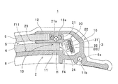
図1に示す看板装置1は、「表示装置」の一例であって、出願人が上記の特許文献に開示した表示装置や、出願人が試作した表示装置と同様にして、電柱等の取付け対象Xに取り付けた状態で表示媒体(広告媒体:紙やフィルムに任意の図柄や記号を印刷したもの:図示せず)を背面側から照らして表示することができるように構成されている。具体的には、看板装置1は、図2〜4に示すように、基体2、一対のLED基板3、導光板4、カバー板5、および一対のキャップ6と、LED基板3に対して電力を供給する(点灯を制御する)図示しないコントローラユニットとを備えて構成されている。
The
基体2は、「基体」の一例であって、全体として正面視長板状に形成されている。この基体2は、主材10、および一対のLED取付け具20を備えている。また、主材10は、本体部11、および本体部11の両端部に設けられた一対の縁板部12,12が、アルミニウムを用いた押出成形によって一体的に形成されて構成されている。
The
本体部11は、「本体部」の一例であって、取付け対象Xの周面形状に応じて、その幅方向(図2,4における左右方向)の断面形状が弧状となるように湾曲させられている。この場合、本例の看板装置1(基体2)では、本体部11における表面側の一面F11(図3,4参照)が、鏡面加工、または白色塗装されており、これにより、後述するように導光板4によって導光されて導光板4の背面側に出射された光を看板装置1の表面側に向かって反射するように構成されている。また、本例の看板装置1(基体2)では、図1に示すように、看板装置1を取付け対象Xに取り付けるためのバンドを挿通可能な複数の挿通用孔11aが本体部11の幅方向における縁部に複数形成されている。なお、同図では、上記のバンドの図示を省略している。
The
縁板部12は、「縁板部」の一例であって、図2,3に示すように、導光板4やカバー板5の幅方向における両端部の表面側(両図における上面側)を覆うようにして本体部11の幅方向における両端部に形成されている。この場合、本例の看板装置1(基体2)では、上記の本体部11の幅方向における端部および縁板部12によって「差込み用溝部」に相当する差込み用溝部13が形成されている。また、本例の看板装置1(基体2)では、図3に示すように、縁板部12の内面(縁板部12における本体部11との対向面)にLED取付け具20を取り付けるための取付け用凸部12aが形成されている。
The
LED取付け具20は、「光源体取付け具」の一例であって、アルミニウムを用いた押出成形によって主材10(本体部11および縁板部12)とは別体に形成されている。このLED取付け具20は、図3に示すように、縁板部12(取付け用凸部12a)に取り付けるための取付け部21、LED基板3を取付け可能な基板取付け部22、後述するように導光板4とカバー板5との間に挟み込まれる保持用リブ23、および「移動規制用段部」を構成する移動規制凸部24が一体的に形成されている。この場合、取付け部21には、縁板部12の取付け用凸部12aを嵌合可能な取付け用凹部21aが形成されている。
The
このLED取付け具20は、後述するように基板取付け部22にLED基板3を取り付けた状態で差込み用溝部13内に配置され、取付け部21の取付け用凹部21aに縁板部12の取付け用凸部12aを嵌合させるようにして縁板部12(主材10)に対して固定される(「本体部および縁板部の少なくとも一方に固定される」との構成が「縁板部に固定される」との構成の例)。
As will be described later, the
LED基板3は、「帯状光源体」の一例であって、図5に示すように、長尺帯状のフレキシブル基板31と、フレキシブル基板31の一面に等間隔で配置された複数のLED32と、LED32と共にフレキシブル基板31の一面に実装された抵抗体や定電流ダイオードなどの保護部品(電子部品の一例)33とを備えている。このLED基板3では、フレキシブル基板31の基板面と交差する向きに光を出射可能に各LED32がフレキシブル基板31に実装されている。この場合、本例の看板装置1では、基体2の幅方向における両端部にLED基板3がそれぞれ取り付けられている(「基体の幅方向における両端部の少なくとも一方に取り付けられ」との構成が「基体の幅方向における両端部の双方に取り付けられ」との構成の例)。
The
導光板4は、「導光板」の一例であって、図2,4に示すように、基体2における本体部11の一面F11に沿って湾曲させられている。この導光板4は、図2に示すように、基体2における本体部11の表面側に配置されて、LED基板3から発せられた光を基体2の幅方向における各部に導光する。この場合、この導光板4は、図3に示すように、LED取付け具20に取り付けられた状態で差込み用溝部13内に配置されたLED基板3からの光が端面F4から入射するように、その幅方向における両端部が差込み用溝部13,13内に差し込まれた状態で基体2に取り付けられている。
The
カバー板5は、「表面板」の一例であって、図2,4に示すように、上記の導光板4と同様にして幅方向に沿って湾曲させられると共に、図2に示すように、導光板4の表面側に配置されて導光板4と共に表示媒体を保持可能に基体2に取り付けられている。この場合、本例の看板装置1では、導光板4およびカバー板5の両板体の端部を差込み可能に差込み用溝部13が形成されている。
The
キャップ6は、基体2(主材10およびLED取付け具20)、LED基板3,3、導光板4およびカバー板5の長手方向における端部を覆う部材であって、図4に示すように、基体2、導光板4およびカバー板5の湾曲形状に合わせて樹脂材料によって弧状に形成されている。このキャップ6は、図1に示すように、一例として、基体2の本体部11に形成されたねじ込み部11b(図3,4参照)に固定ねじ6a(図1,3参照)をネジ込むことによって本体部11に固定されている。
The
この看板装置1の製造に際しては、押出成形によって主材10およびLED取付け具20をそれぞれ製作する。また、任意の厚みの樹脂平板を加熱プレスすることによって断面弧状の導光板4およびカバー板5をそれぞれ製作すると共に、射出成型によってキャップ6を製作する。
When manufacturing the
次いで、図6に示すように、LED取付け具20の基板取付け部22にLED基板3を取り付ける。この場合、LED基板3のフレキシブル基板31に粘着テープが貼付されている場合には、その台紙を剥離してフレキシブル基板31を基板取付け部22に貼り付け、粘着テープが貼付されていない場合には、接着剤によってフレキシブル基板31を基板取付け部22に接着する。この際には、非常に狭い空間内にLED光源を挿入する必要があった従来の表示装置の製造時とは異なり、剥き出し状態の基板取付け部22に対してLED基板3を貼り付ける(または接着する)ことでLED取付け具20にLED基板3を固定できるため、この種の作業に不慣れな者であっても、LED基板3を破損することなく、短時間で容易に作業を完了させることができる。
Next, as shown in FIG. 6, the
続いて、図7に示すように、主材10における縁板部12の取付け用凸部12aをLED取付け具20の取付け部21における取付け用凹部21aに嵌合させるようにして、主材10の差込み用溝部13内にLED取付け具20を収容する。この際には、取付け用凸部12aの突端部に形成された半円形溝部と、取付け用凹部21aの底面に形成された半円形溝部とが対向させられた状態となり、同図に示すように丸孔Hが形成される。次いで、主材10およびLED取付け具20の長手方向における端部において丸孔H内に無頭ねじをねじ込む。これにより、主材10(縁板部12)に対してLED取付け具20が固定されて基体2が完成し、基体2に対するLED基板3の取り付けが完了した状態となる。
Subsequently, as shown in FIG. 7, the mounting
次いで、図8に示すように、幅方向における両端部を差込み用溝部13に差し込むようにして基体2に導光板4を取り付ける。この際には、主材10における本体部11とLED取付け具20における保持用リブ23との間に挿入するようにして導光板4を取り付ける。この場合、本例の看板装置1(基体2)では、LED取付け具20に形成された移動規制凸部24によって「移動規制用段部」が形成されており、これにより、基体2に対する導光板4の幅方向への移動が規制されている。したがって、LED取付け具20(基板取付け部22)に取り付けられているLED基板3に導光板4の端面F4が当接してLED基板3が破損する事態が好適に回避される。
Next, as shown in FIG. 8, the
続いて、図9に示すように、幅方向における両端部を基体2の差込み用溝部13に差し込むようにして基体2にカバー板5を取り付ける。この際には、主材10における縁板部12とLED取付け具20における保持用リブ23との間に挿入するようにしてカバー板5を取り付ける。なお、看板装置1の構成および組立て方法についての理解を容易とするために、図示および詳細な説明を省略するが、一例として、基体2に対するカバー板5の取付けに先立ち、縁板部12と保持用リブ23との間にシール材(可逆変形可能な弾性材)を挿入しておき、その状態でカバー板5を挿入してシール材を圧縮変形させることにより、基体2(縁板部12)とカバー板5との間をシーリングすることができる。
Subsequently, as shown in FIG. 9, the
次いで、基体2、LED基板3,3、導光板4およびカバー板5の長手方向における両端部にキャップ6をそれぞれ装着する。この場合、本例の看板装置1では、図9に示すように、キャップ6を装着していない状態において導光板4とカバー板5との間の隙間が幅方向における中央部寄りほど大きくなるようにカバー板5が湾曲させられている。このような状態においてキャップ6を装着することによってカバー板5がキャップ6によって押さえ付けられて、同図に破線で示すように弾性変形させられる。これにより、キャップ6,6の装着が完了した状態においては、導光板4とカバー板5との間に、保持用リブ23の厚みと等しい均一な隙間Sが形成される。以上により、図1〜3に示すように看板装置1が完成する。
Next, caps 6 are respectively attached to both ends in the longitudinal direction of the
この看板装置1の使用に際しては、両キャップ6,6のいずれか一方を取り外して導光板4およびカバー板5の間の隙間Sに表示媒体を差し込む。この際には、導光板4とカバー板5との間にLED取付け具20における保持用リブ23の厚みと等しい隙間Sが形成されているため、この隙間Sに表示媒体をスムーズに差し込むことができる。次いで、取り外したキャップ6を基体2(本体部11)に再び装着する。これにより、LED基板3,3から発せられて導光板4によって導光された光によって表示媒体を裏面側から照らすことが可能な状態となる。
When using the
一方、上記の看板装置1におけるLED基板3とは光の出射方向(光拡散性)が相違する「帯状光源体」や、LED基板3とは大きさ(幅や厚み)が相違する「帯状光源体」を採用して「表示装置」を製造するとき、または、看板装置1におけるLED基板3をそれらの「帯状光源体」に交換するときには、使用する「帯状光源体」に応じた「光源体取付け具」を製作する。
On the other hand, the “band light source” having a different light emission direction (light diffusibility) from the
具体的には、図10に示す看板装置1では、前述したLED基板3とは光の出射方向(光拡散性)が相違するLED基板3Aの使用を考慮してLED取付け具20の基板取付け部22とは延出角度が相違する基板取付け部22Aを備えたLED取付け具20Aが採用されて基体2Aが構成されている。なお、同図に示す看板装置1、および後に参照する図11に示す看板装置1において上記の看板装置1と同様の機能を有する構成要素については、同一の符号を付して重複する説明を省略する。
Specifically, in the
また、図11に示す看板装置1では、前述したLED基板3,3Aとは光の出射方向が相違するLED基板3Bの使用を考慮してLED取付け具20の基板取付け部22やLED取付け具20Aの基板取付け部22Aとは異なる形状の基板取付け部22Bを備えたLED取付け具20Bが採用されて基体2Bが構成されている。この場合、上記のLED基板3Bは、複数のLED32および図示しない保護部品33が相互に結線された状態においてモールド材34によってモールドされて、全体として長尺帯状に形成されている。
Further, in the
これらの例のように、この看板装置1では、使用する「帯状光源体」に応じてLED取付け具20,20A,20B・・を製作することにより、主材10、導光板4、カバー板5およびキャップ6などを共用して各種の「帯状光源体」を備えた看板装置1を製造することが可能となっている。なお、上記のLED取付け具20,20A,20B等が主材10よりも小形であり、また、LED取付け具20,20A,20B等の各構成要素が主材10の本体部11などよりも薄厚であるため、LED取付け具20,20A,20B等を押出成形するための金型については、主材10を押出成形するための金型よりも安価に製作することができる。
As in these examples, in this
このように、この看板装置1では、本体部11、および本体部11の幅方向における両端部に設けられた一対の縁板部12を備えて導光板4を差込み可能な一対の差込み用溝部13が形成されると共に、本体部11および両縁板部12とは別体に形成されてLED基板3,3A,3Bを取付け可能に構成され、かつ両差込み用溝部13内に配置された状態で縁板部12に固定されるLED取付け具20,20A,20Bを備えて基体2,2A,2Bが構成されている。
Thus, in this
したがって、この看板装置1によれば、LED取付け具20,20A,20Bに対してLED基板3,3A,3Bを予め取り付けておき、その後にLED取付け具20,20A,20Bを縁板部12に取り付けることでLED基板3,3A,3Bを位置決めすることができるため、この種の装置の組立て作業に不慣れな者であっても、短時間で容易に看板装置1を製造することができる。これにより、看板装置1の製造コストを十分に低減することができる。また、大きさなどが相違する各種のLED基板3,3A,3Bを使用する際に、それらに応じたLED取付け具20,20A,20Bを製作することで、部品コストがやや高い主材10(本体部11および縁板部12)を共用して看板装置1を製造することができるため、使用する「帯状光源体」に応じて新たな「基体」を製作する必要がなくなる分だけ、看板装置1の製造コストを一層低減することができる。
Therefore, according to the
また、この看板装置1によれば、基体2,2A,2Bに対する導光板4の幅方向への移動を規制する「移動規制用段部」を構成する移動規制凸部24をLED取付け具20,20A,20Bに設けたことにより、看板装置1に加わる振動や衝撃に起因して導光板4が基体2,2A,2Bに対して相対的に移動しようとしても、その端面F4がLED基板3,3A,3Bに当接しないため、導光板4によってLED基板3,3A,3Bが破壊されるのを好適に回避することができる。
Further, according to the
さらに、この看板装置1によれば、導光板4と共に「表示媒体」を保持するカバー板5を備えると共に、導光板4およびカバー板5を差込み可能に両差込み用溝部13を基体2,2A,2Bに形成したことにより、カバー板5によって覆われる「表示媒体」に水濡れや傷付きが生じるのを好適に回避することができるだけでなく、カバー板5を縁板部12の表面側に配置する構成(例えば、カバー板5の端面が見える状態でカバー板5を貫通させた固定用ねじを縁板部12にねじ込むことで固定する構成)とは異なり、看板装置1の美観を十分に向上させることができると共に、看板装置1に加わる振動や衝撃に起因してカバー板5が外れる事故を好適に回避することができる。
Furthermore, according to this
また、この看板装置1によれば、幅方向の断面形状が弧状となるように本体部11を湾曲させると共に、本体部11の表面側の一面に沿って導光板4を湾曲させたことにより、円柱状(または円筒状)の取付け対象Xの周面に沿わせて看板装置1を取り付けることができ、これにより、取付け対象Xの美観や機能を損なうことなく、恰も取付け対象Xの周面の一部(看板装置1を取り付けた部位)が発光しているかのような趣向性の高い表示を行うことができる。また、全体的に湾曲形状であることで組立て作業が困難であるように見えるものの、LED基板3,3A,3Bを予め取り付けておいたLED取付け具20,20A,20Bを縁板部12に取り付け、その後に導光板4の両端部を差込み用溝部13に差し込むことで基体2,2A,2Bに取り付けることができるため、不慣れな者であっても短時間で容易に看板装置1を製造することができる。
Further, according to this
また、この看板装置1によれば、導光板4およびカバー板5の間に位置させられて本体部11と共に導光板4を保持すると共に縁板部12と共にカバー板5を保持する保持用リブ23をLED取付け具20,20A,20Bに設けたことにより、導光板4とカバー板5とを保持用リブ23の厚みの分だけ確実に離間させて導光板4とカバー板5との間に隙間Sを生じさせることができるため、この隙間Sに「表示媒体」をスムーズに挿入することができる。
Further, according to the
次に、「表示装置」の他の実施の形態について説明する。 Next, another embodiment of the “display device” will be described.
幅方向の断面形状が弧状となるように湾曲させた本体部11、導光板4およびカバー板5を備えた看板装置1を「表示装置」の一例として説明したが、平板状の「本体部」を有する「基部」、平板状の「導光板」、および平板状の「表面板」を備えて「表示装置」を構成することもできる。
The
例えば、図12に示す看板装置51は、「表示装置」の他の一例であって、図示しないスタンド(保持具)にセットされた状態で任意の平面上に自立させて使用することができるように構成されている。また、この看板装置51は、その一方の面および他方の面の両面に表示媒体(広告媒体)をそれぞれセットして各々の背面側(看板装置51の内側)から照らして表示することができるように構成されている。この看板装置51は、図13〜15に示すように、基体52、4つのLED基板3、一対の導光板54、一対のカバー板55、および一対のキャップ56と、LED基板3に対して電力を供給する(点灯を制御する)図示しないコントローラユニットとを備えて構成されている。
For example, the
基体52は、「基体」の他の一例であって、全体として正面視長板状に形成されている。この基体52は、主材60、および4つのLED取付け具70を備えている。また、主材60は、本体部61、および本体部61の一面F61a,F61bにおける両端部にそれぞれ設けられた縁板部62が、アルミニウムを用いた押出成形によって一体的に形成されて構成されている。
The
本体部61は、「本体部」の他の一例であって、正面視長板状(長尺で平坦な平板状)に形成されている。この場合、本例の看板装置51(基体52)では、本体部61の一面F61a,F61bが、鏡面加工、または白色塗装されており、これにより、後述するように導光板54によって導光されて導光板54の背面側に出射された光を看板装置51の一方の面側および他方の面側に向かってそれぞれ反射するように構成されている。
The
縁板部62は、「縁板部」の他の一例であって、導光板54やカバー板55の幅方向における両端部の表面側を覆うようにして本体部61の一面F61a,F61bにおける幅方向の両端部にそれぞれ形成されている。この場合、本例の看板装置51(基体52)では、上記の本体部61の幅方向における端部および縁板部62によって「差込み用溝部」に相当する差込み用溝部63が形成されている。
The
また、本例の看板装置51(基体52)では、図14に示すように、本体部61の幅方向における端部、各縁板部62、本体部61の一面F61a,F61bにそれぞれ形成された凸部61a、および各縁板部62の内面にそれぞれ形成された凸部62aによって、LED取付け具70を取り付けるための取付け部64が各差込み用溝部63の奥側にそれぞれ形成されている。
Further, in the signboard device 51 (base 52) of the present example, as shown in FIG. 14, the end portion in the width direction of the
LED取付け具70は、「光源体取付け具」の他の一例であって、アルミニウムを用いた押出成形によって主材60(本体部61および縁板部62)とは別体に形成されている。このLED取付け具70は、図14に示すように、取付け部64に取り付けるための取付け部71、LED基板3を取付け可能な基板取付け部72、後述するように導光板54とカバー板55との間に挟み込まれる保持用リブ73、および「移動規制用段部」を構成する移動規制凸部74が一体的に形成されている。なお、本例のLED取付け具70では、取付け部71の一部を兼用して基板取付け部72が形成されている。
The
このLED取付け具70は、後述するように基板取付け部72にLED基板3を取り付けた状態で差込み用溝部63内の取付け部64に取付け部71が嵌入されるようにして主材60に対して固定される(「本体部および縁板部の少なくとも一方に固定される」との構成が「本体部および縁板部の双方に固定される」との構成の例)。
As will be described later, the
導光板54は、「導光板」の他の一例であって、正面視長板状(長尺で平坦な平板状)に形成されている。この導光板54は、図13に示すように、基体52における本体部61の一面F61a,F61bに沿ってそれぞれ配置されて、各LED基板3から発せられた光を基体52の幅方向における各部に導光する。この場合、この導光板54は、図14に示すように、LED取付け具70に取り付けられた状態で差込み用溝部63内に配置されたLED基板3からの光が端面F54から入射するように、その幅方向における両端部が差込み用溝部63,63内に差し込まれた状態で基体52に取り付けられている。
The
カバー板55は、「表面板」の他の一例であって、上記の導光板54と同様にして正面視長板状(長尺で平坦な平板状)に形成されると共に、図13に示すように、両導光板54の表面側にそれぞれ配置されて導光板54と共に表示媒体を保持可能に基体52に取り付けられている。この場合、本例の看板装置51では、導光板54およびカバー板55の両板体の端部を差込み可能に差込み用溝部63がそれぞれ形成されている。
The
キャップ56は、基体52(主材60およびLED取付け具70)、LED基板3、導光板54およびカバー板55の長手方向における端部を覆うことができるように構成されている。なお、本例の看板装置51では、図示しない固定用ねじによって基体52の主材60にキャップ56が固定される構成が採用されているが、固定用ねじについての図示および詳細な説明を省略する。
The
この看板装置51の製造に際しては、押出成形によって主材60およびLED取付け具70をそれぞれ製作する。また、任意の厚みの樹脂平板を長板状に切断することによって導光板54およびカバー板55をそれぞれ製作すると共に、射出成型によってキャップ56を製作する。なお、以下の説明において前述した看板装置1の製作手順と同様の工程については、詳細な説明を省略する。
In manufacturing the
次いで、LED取付け具70の基板取付け部72にLED基板3を取り付ける。この際には、非常に狭い空間内にLED光源を挿入する必要があった従来の表示装置の製造時とは異なり、剥き出し状態の基板取付け部72に対してLED基板3を貼り付ける(または接着する)ことでLED取付け具70にLED基板3を固定できるため、この種の作業に不慣れな者であっても、LED基板3を破損することなく、短時間で容易に作業を完了させることができる。
Next, the
続いて、主材60における長手方向の端部から取付け部71を取付け部64に嵌合させるようにして、差込み用溝部63内にLED取付け具70を収容する。これにより、主材60に対してLED取付け具70が固定されて基体52が完成し、基体52に対するLED基板3の取り付けが完了した状態となる。
Subsequently, the
次いで、幅方向における両端部を差込み用溝部63に差し込むようにして基体52に導光板54を取り付ける。この際には、主材60における本体部61とLED取付け具70における保持用リブ73との間に挿入するようにして導光板54を取り付ける。この場合、本例の看板装置51(基体52)では、LED取付け具70に形成された移動規制凸部74および主材60の本体部61に形成された凸部61aによって「移動規制用段部」が形成されており、これにより、基体52に対する導光板54の幅方向への移動が規制されている。したがって、LED取付け具70(基板取付け部72)に取り付けられているLED基板3に導光板54の端面F54が当接してLED基板3が破損する事態が好適に回避される。
Next, the
続いて、幅方向における両端部を基体52の差込み用溝部63に差し込むようにして基体52にカバー板55を取り付ける。この際には、主材60における縁板部62とLED取付け具70における保持用リブ73との間に挿入するようにしてカバー板55を取り付ける。次いで、基体52、LED基板3、導光板54およびカバー板55の長手方向における両端部にキャップ56をそれぞれ装着する。以上により、図12〜14に示すように看板装置51が完成する。
Subsequently, the
この看板装置51の使用に際しては、両キャップ56,56のいずれか一方を取り外して導光板54およびカバー板55の間の隙間Sに表示媒体を差し込む。この際には、導光板54とカバー板55との間にLED取付け具70における保持用リブ73の厚みと等しい隙間Sが形成されているため、この隙間Sに表示媒体をスムーズに差し込むことができる。次いで、取り外したキャップ56を基体52(本体部61)に再び装着する。これにより、LED基板3から発せられて導光板54によって導光された光によって表示媒体を裏面側(看板装置51の内側)から照らすことが可能な状態となる。
When using the
なお、図示および詳細な説明を省略するが、上記の看板装置51におけるLED基板3とは光の出射方向(光拡散性)が相違する「帯状光源体」や、LED基板3とは大きさ(幅や厚み)が相違する「帯状光源体」を採用して「表示装置」を製造するとき、または、看板装置51におけるLED基板3をそれらの「帯状光源体」に交換するときには、使用する「帯状光源体」に応じた「光源体取付け具」を使用する。これにより、前述した看板装置1と同様にして、この看板装置51においても、主材60、導光板54、カバー板55およびキャップ56などを共用しつつ、使用する「帯状光源体」に応じて製作した「光源体取付け具」を使用して各種の「帯状光源体」を備えた看板装置51を製造することが可能となっている。
In addition, although illustration and detailed description are abbreviate | omitted, a "strip | belt-shaped light source body" in which the light emission direction (light diffusibility) differs from
このように、この看板装置51では、本体部61、および本体部61の幅方向における両端部に設けられた一対の縁板部62を備えて導光板54を差込み可能な一対の差込み用溝部63が一方の面および他方の面にそれぞれ形成されると共に(表裏両面が「表面」に相当する構成)、本体部61および両縁板部62とは別体に形成されてLED基板3などを取付け可能に構成され、かつ両差込み用溝部63内に配置された状態で取付け部64(本体部61および縁板部62)に固定されるLED取付け具70を備えて基体52が構成されている。
Thus, in this
したがって、この看板装置51によれば、LED取付け具70に対してLED基板3を予め取り付けておき、その後にLED取付け具70を取付け部64に取り付けることでLED基板3を位置決めすることができるため、この種の装置の組立て作業に不慣れな者であっても、短時間で容易に看板装置51を製造することができる。これにより、看板装置51の製造コストを十分に低減することができる。また、大きさなどが相違する各種のLED基板(帯状光源体)を使用する際に、それらに応じたLED取付け具(光源体取付け具)を製作することで、部品コストがやや高い主材60(本体部61および縁板部62)を共用して看板装置51を製造することができるため、使用する「帯状光源体」に応じて新たな「基体」を製作する必要がなくなる分だけ、看板装置51の製造コストを一層低減することができる。
Therefore, according to this
また、この看板装置51によれば、基体52に対する導光板54の幅方向への移動を規制する「移動規制用段部」を構成する移動規制凸部74をLED取付け具70に設けたことにより、看板装置51に加わる振動や衝撃に起因して導光板54が基体52に対して相対的に移動しようとしても、その端面F54がLED基板3に当接しないため、導光板54によってLED基板3が破壊されるのを好適に回避することができる。
Further, according to this
さらに、この看板装置51によれば、導光板54と共に「表示媒体」を保持するカバー板55を備えると共に、導光板54およびカバー板55を差込み可能に差込み用溝部63を基体52に形成したことにより、カバー板55によって覆われる「表示媒体」に水濡れや傷付きが生じるのを好適に回避することができるだけでなく、カバー板55を縁板部62の表面側に配置する構成(例えば、カバー板55の端面が見える状態でカバー板55を貫通させた固定用ねじを縁板部62にねじ込むことで固定する構成)とは異なり、看板装置51の美観を十分に向上させることができると共に、看板装置51に加わる振動や衝撃に起因してカバー板55が外れる事故を好適に回避することができる。
Furthermore, according to this
また、この看板装置51によれば、導光板54およびカバー板55の間に位置させられて本体部61と共に導光板54を保持すると共に縁板部62と共にカバー板55を保持する保持用リブ73をLED取付け具70に設けたことにより、導光板54とカバー板55とを保持用リブ73の厚みの分だけ確実に離間させて導光板54とカバー板55との間に隙間Sを生じさせることができるため、この隙間Sに「表示媒体」をスムーズに挿入することができる。
Further, according to the
なお、「表示装置」の構成は、上記の看板装置1,51の構成の例に限定されない。例えば、基体2,2A,2Bの両端部にLED基板3,3A,3Bをそれぞれ配設した看板装置1や、基体52の両端部にLED基板3をそれぞれ配設した看板装置51を例に挙げて説明したが、「帯状光源体」から十分な光量の光を出射できる場合や、「基体」の幅が狭い場合などには、「基体」の幅方向における両端部の一方だけに「帯状光源体」を配設して「表示装置」を構成することもできる(図示せず)。
The configuration of the “display device” is not limited to the configuration example of the
また、押出成形によって本体部11と縁板部12と一体に形成した主材10を備えた基体2や、押出成形によって本体部61と縁板部62と一体に形成した主材60を備えた基体52を例に挙げて説明したが、「本体部」および「縁板部」を別体に形成した後に、溶接、ねじ止めまたは嵌合などによってこれらを一体化する構成を採用することもできる。
Moreover, the base |
さらに、縁板部12に対してLED取付け具20を固定する構成を採用した看板装置1(基体2)や、本体部61および縁板部62によって構成される取付け部64に対してLED取付け具70を固定する構成(本体部61および縁板部62の双方に対してLED取付け具70を固定する構成)を採用した看板装置51(基体52)を例に挙げて説明したが、「本体部」に対して「光源体取付け具」を固定する構成(図示せず)を採用することもできる。
Furthermore, the LED fixture is attached to the signboard device 1 (base 2) adopting a configuration in which the
また、「本体部」や「縁板部」に対する「光源体取付け具」の固定構造は、取付け用凹部21aに取付け用凸部12aを嵌合させて無頭ねじで固定する基体2,2A,2Bのような構成や、取付け部64に取付け部71を嵌合させて固定する基体52のような構成の例に限定されず、「本体部」や「縁板部」を貫通させたねじによって「光源体取付け具」を固定する構成や、接着剤によって「光源体取付け具」を固定する構成を採用することができる(図示せず)。
Further, the fixing structure of the “light source body fixture” with respect to the “main body portion” and the “edge plate portion” is the
さらに、「表示媒体」が水濡れする心配のない環境下で使用したり、「表示媒体」を耐水性素材で製作したりする場合には、「表面板(カバー板5,55)」を設けずに、導光板4,54の表面側に貼付した「表示媒体」を剥き出したままとすることもできる。また、LED32を有するLED基板3,3A,3Bを備えた構成を例に挙げて説明したが、蛍光管などを光源として備えた各種の「帯状光源体」を採用して「表示装置」を構成することができる。
In addition, a “surface plate (cover
さらに、電柱等の取付け対象X取付け可能な看板装置1の構成を例に挙げて説明したが、鉄道車両や通路における天井の角部に取り付けて使用可能に構成することもできる。この場合、天井の角部に取付けて使用する場合には、「基体」、「導光板」および「表面板」などの湾曲の向きを看板装置1とは逆向きにすればよい(図示せず)。また、一方の面および他方の面の両面に「表示媒体」を配設可能に構成した看板装置51を例に挙げて説明したが、いずれか一方の面だけに「表示媒体」を配設可能に構成することもできる(図示せず)。
Furthermore, although the configuration of the
1,51 看板装置
2,2A,2B,52 基体
3,3A,3B LED基板
4,54 導光板
5,55 カバー板
6,56 キャップ
11,61 本体部
12,62 縁板部
12a 取付け用凸部
13,63 差込み用溝部
20,20A,20B,70 LED取付け具
21,71 取付け部
21a 取付け用凹部
22,22A,22B,72 基板取付け部
23,73 保持用リブ
24,74 移動規制凸部
64 取付け部
74 移動規制凸部
F4,F54 端面
F11,F61a,F61b 一面
S 隙間
DESCRIPTION OF
Claims (6)
前記基体は、正面視長板状の本体部、および当該本体部の前記幅方向における両端部に設けられて前記導光板の幅方向における両端部の前記表面側を覆う一対の縁板部を備えて当該本体部の当該両端部および当該両縁板部によって当該導光板を差込み可能な一対の差込み用溝部が形成されると共に、前記本体部および前記両縁板部とは別体に形成されて前記帯状光源体を取付け可能に構成され、かつ前記両差込み用溝部内に配置された状態で当該本体部および当該縁板部の少なくとも一方に固定される光源体取付け具を備え、
前記導光板は、前記光源体取付け具に取り付けられた前記帯状光源体からの光が前記幅方向における端面から入射可能に当該幅方向における前記両端部が前記両差込み用溝部内に差し込まれた状態で前記基体に取り付けられている表示装置。 A base plate having a long plate shape in front view, a strip-like light source body attached to at least one of both end portions in the width direction of the base body, and disposed along the one surface side of the base body and attached to the base body and the strip-like light source body A light guide plate that guides light emitted from a light source body to each part in the width direction of the substrate, and a display device configured to be able to dispose a display medium on the surface side of the light guide plate,
The base body includes a main body having a long plate shape when viewed from the front, and a pair of edge plates that are provided at both end portions in the width direction of the main body portion and cover the surface side of both end portions in the width direction of the light guide plate. A pair of insertion groove portions into which the light guide plate can be inserted are formed by the both end portions and the both edge plate portions of the main body portion, and are formed separately from the main body portion and the both edge plate portions. A light source body fixture that is configured to be attachable to the belt-shaped light source body and is fixed to at least one of the main body portion and the edge plate portion in a state of being disposed in the both insertion groove portions,
The light guide plate is in a state in which both end portions in the width direction are inserted into the insertion groove portions so that light from the band-shaped light source body attached to the light source body attachment member can be incident from an end surface in the width direction. A display device attached to the substrate.
前記基体は、前記導光板および前記表面板を差込み可能に前記両差込み用溝部が形成されている請求項1または2記載の表示装置。 A surface plate that is disposed along one surface of the light guide plate and that holds the display medium together with the light guide plate;
The display device according to claim 1, wherein the base has the insertion groove formed so that the light guide plate and the surface plate can be inserted.
前記導光板は、前記本体部の前記表面側の一面に沿って湾曲させられている請求項1または2記載の表示装置。 The main body is curved so that the cross-sectional shape in the width direction is arcuate,
The display device according to claim 1, wherein the light guide plate is curved along one surface of the main body portion on the surface side.
前記基体は、前記導光板および前記表面板を差込み可能に前記両差込み用溝部が形成されている請求項4記載の表示装置。 A surface plate that is curved along the width direction and that is disposed along one surface of the light guide plate and holds the display medium together with the light guide plate;
The display device according to claim 4, wherein the insertion groove is formed on the base body so that the light guide plate and the surface plate can be inserted.
Priority Applications (5)
| Application Number | Priority Date | Filing Date | Title |
|---|---|---|---|
| TW105138215A TWI621109B (en) | 2016-07-04 | 2016-11-22 | Display device |
| CN201611109138.0A CN107578716B (en) | 2016-07-04 | 2016-12-06 | display device |
| EP17823782.2A EP3422330B1 (en) | 2016-07-04 | 2017-01-20 | Signboard apparatus |
| US16/081,790 US10553136B2 (en) | 2016-07-04 | 2017-01-20 | Display apparatus |
| PCT/JP2017/001868 WO2018008173A1 (en) | 2016-07-04 | 2017-01-20 | Display device |
Applications Claiming Priority (2)
| Application Number | Priority Date | Filing Date | Title |
|---|---|---|---|
| JP2016132147 | 2016-07-04 | ||
| JP2016132147 | 2016-07-04 |
Related Child Applications (1)
| Application Number | Title | Priority Date | Filing Date |
|---|---|---|---|
| JP2016189030A Division JP2018010267A (en) | 2016-07-04 | 2016-09-28 | Display device |
Publications (2)
| Publication Number | Publication Date |
|---|---|
| JP6022101B1 true JP6022101B1 (en) | 2016-11-09 |
| JP2018010264A JP2018010264A (en) | 2018-01-18 |
Family
ID=57247423
Family Applications (2)
| Application Number | Title | Priority Date | Filing Date |
|---|---|---|---|
| JP2016143927A Active JP6022101B1 (en) | 2016-07-04 | 2016-07-22 | Display device |
| JP2016189030A Pending JP2018010267A (en) | 2016-07-04 | 2016-09-28 | Display device |
Family Applications After (1)
| Application Number | Title | Priority Date | Filing Date |
|---|---|---|---|
| JP2016189030A Pending JP2018010267A (en) | 2016-07-04 | 2016-09-28 | Display device |
Country Status (6)
| Country | Link |
|---|---|
| US (1) | US10553136B2 (en) |
| EP (1) | EP3422330B1 (en) |
| JP (2) | JP6022101B1 (en) |
| CN (1) | CN107578716B (en) |
| TW (1) | TWI621109B (en) |
| WO (1) | WO2018008173A1 (en) |
Cited By (1)
| Publication number | Priority date | Publication date | Assignee | Title |
|---|---|---|---|---|
| JP6067918B1 (en) * | 2016-09-28 | 2017-01-25 | 有限会社エーユー建築工房 | Display device |
Families Citing this family (4)
| Publication number | Priority date | Publication date | Assignee | Title |
|---|---|---|---|---|
| US10902757B2 (en) * | 2017-05-11 | 2021-01-26 | Tyler J Ross | Sign illumination system and fastening device with integral illumination |
| CO2018012392A1 (en) * | 2018-11-16 | 2020-05-29 | Pretensados De Concreto Del Oriente Pretecor Ltda | Smart pole and method to control said pole |
| US11927316B2 (en) * | 2020-07-22 | 2024-03-12 | TraffiCalm Systems, LLC | Sign post flasher assembly |
| KR102333985B1 (en) * | 2021-01-12 | 2021-12-02 | 배현진 | Wearable smart device |
Citations (6)
| Publication number | Priority date | Publication date | Assignee | Title |
|---|---|---|---|---|
| JPS4610270Y1 (en) * | 1966-08-05 | 1971-04-10 | ||
| JPH09127896A (en) * | 1995-10-31 | 1997-05-16 | Takiron Co Ltd | Surface light emitting body |
| JP2004157204A (en) * | 2002-11-05 | 2004-06-03 | Sekisui Jushi Co Ltd | Internally lighting type display system |
| JP2010033862A (en) * | 2008-07-29 | 2010-02-12 | Shikoku Instrumentation Co Ltd | Led lighting panel for outdoor use |
| JP2012037643A (en) * | 2010-08-05 | 2012-02-23 | Fuji Electric Fa Components & Systems Co Ltd | Display device |
| WO2015174339A1 (en) * | 2014-05-13 | 2015-11-19 | 有限会社エーユー建築工房 | Display device |
Family Cites Families (8)
| Publication number | Priority date | Publication date | Assignee | Title |
|---|---|---|---|---|
| JPS5610499A (en) | 1979-07-05 | 1981-02-02 | Yoshikazu Yui | Automatic enclosing and sealing machine for long envelope |
| JPH03203772A (en) | 1989-12-29 | 1991-09-05 | Meitaku Syst:Kk | Thin surface light source device |
| US20040095741A1 (en) * | 2002-11-14 | 2004-05-20 | Shao-Hsiung Chen | Side-illuminated advertisement board |
| TWM350730U (en) * | 2008-06-27 | 2009-02-11 | zhen-qin Zhang | Band-shaped light-source generating apparatus |
| US8958024B2 (en) * | 2012-07-17 | 2015-02-17 | Shenzhen China Star Optoelectronics Technology Co., Lt | Back plate, backlight module and liquid crystal display device |
| US9739932B2 (en) | 2013-09-24 | 2017-08-22 | Sakai Display Products Corporation | Light source module and display apparatus |
| KR102169102B1 (en) * | 2013-12-04 | 2020-10-23 | 삼성디스플레이 주식회사 | Bottom chassis for display device and display device comprising the same |
| CN104167161B (en) * | 2014-09-02 | 2017-03-08 | 马争 | A kind of lamp box Quick connection part and lamp box |
-
2016
- 2016-07-22 JP JP2016143927A patent/JP6022101B1/en active Active
- 2016-09-28 JP JP2016189030A patent/JP2018010267A/en active Pending
- 2016-11-22 TW TW105138215A patent/TWI621109B/en active
- 2016-12-06 CN CN201611109138.0A patent/CN107578716B/en active Active
-
2017
- 2017-01-20 WO PCT/JP2017/001868 patent/WO2018008173A1/en active Application Filing
- 2017-01-20 US US16/081,790 patent/US10553136B2/en active Active
- 2017-01-20 EP EP17823782.2A patent/EP3422330B1/en active Active
Patent Citations (6)
| Publication number | Priority date | Publication date | Assignee | Title |
|---|---|---|---|---|
| JPS4610270Y1 (en) * | 1966-08-05 | 1971-04-10 | ||
| JPH09127896A (en) * | 1995-10-31 | 1997-05-16 | Takiron Co Ltd | Surface light emitting body |
| JP2004157204A (en) * | 2002-11-05 | 2004-06-03 | Sekisui Jushi Co Ltd | Internally lighting type display system |
| JP2010033862A (en) * | 2008-07-29 | 2010-02-12 | Shikoku Instrumentation Co Ltd | Led lighting panel for outdoor use |
| JP2012037643A (en) * | 2010-08-05 | 2012-02-23 | Fuji Electric Fa Components & Systems Co Ltd | Display device |
| WO2015174339A1 (en) * | 2014-05-13 | 2015-11-19 | 有限会社エーユー建築工房 | Display device |
Cited By (1)
| Publication number | Priority date | Publication date | Assignee | Title |
|---|---|---|---|---|
| JP6067918B1 (en) * | 2016-09-28 | 2017-01-25 | 有限会社エーユー建築工房 | Display device |
Also Published As
| Publication number | Publication date |
|---|---|
| US10553136B2 (en) | 2020-02-04 |
| TWI621109B (en) | 2018-04-11 |
| US20190096294A1 (en) | 2019-03-28 |
| WO2018008173A1 (en) | 2018-01-11 |
| EP3422330A1 (en) | 2019-01-02 |
| JP2018010264A (en) | 2018-01-18 |
| EP3422330A4 (en) | 2019-10-23 |
| JP2018010267A (en) | 2018-01-18 |
| CN107578716A (en) | 2018-01-12 |
| TW201802780A (en) | 2018-01-16 |
| EP3422330B1 (en) | 2021-07-21 |
| CN107578716B (en) | 2019-09-24 |
Similar Documents
| Publication | Publication Date | Title |
|---|---|---|
| JP6022101B1 (en) | Display device | |
| US10018311B2 (en) | Lighting device and corresponding mounting housing, kit and method | |
| KR102367068B1 (en) | Display apparatus | |
| JP2009042360A (en) | Illumination light display device | |
| JP6163271B2 (en) | Designable light emitting device | |
| JP5942100B2 (en) | Lamp | |
| WO2015102052A1 (en) | Light source apparatus and display apparatus | |
| KR101558421B1 (en) | LED channel signboard | |
| KR20180000639U (en) | Sign Character And Solid Signboard | |
| KR101041976B1 (en) | Advertising signboard | |
| JP6528442B2 (en) | Optical connection light guide | |
| JPWO2014195988A1 (en) | Designable light emitting device and light diffusing member | |
| KR20170027470A (en) | apparatus of advertisement with lighting for attachment to glass | |
| JP6517724B2 (en) | Planar lighting device | |
| JP6277743B2 (en) | Waterproof case and waterproof guide light | |
| JP6067918B1 (en) | Display device | |
| US20150348725A1 (en) | Sub-assembling method, sub-assembled unit, and apparatus with sub-assembled unit | |
| JP7360153B2 (en) | Receiving member for internally illuminated signs, internally illuminated signs, and how to assemble internally illuminated signs | |
| JP2018013778A (en) | Light guide plate unit | |
| KR101597700B1 (en) | Both face lighting type LED signboard | |
| JP2005283782A (en) | Sign board | |
| KR20200001210U (en) | A double-sided billboard | |
| JP6647026B2 (en) | Light distribution control element holding structure and surface light source device | |
| CN205402275U (en) | Backlight module | |
| KR20120004812U (en) | Line Bar Device |
Legal Events
| Date | Code | Title | Description |
|---|---|---|---|
| TRDD | Decision of grant or rejection written | ||
| A975 | Report on accelerated examination |
Free format text: JAPANESE INTERMEDIATE CODE: A971005 Effective date: 20160902 |
|
| A01 | Written decision to grant a patent or to grant a registration (utility model) |
Free format text: JAPANESE INTERMEDIATE CODE: A01 Effective date: 20160913 |
|
| A61 | First payment of annual fees (during grant procedure) |
Free format text: JAPANESE INTERMEDIATE CODE: A61 Effective date: 20161004 |
|
| R150 | Certificate of patent or registration of utility model |
Ref document number: 6022101 Country of ref document: JP Free format text: JAPANESE INTERMEDIATE CODE: R150 |
|
| R250 | Receipt of annual fees |
Free format text: JAPANESE INTERMEDIATE CODE: R250 |
|
| R250 | Receipt of annual fees |
Free format text: JAPANESE INTERMEDIATE CODE: R250 |