JP5997133B2 - Method for stripping nitride coating - Google Patents
Method for stripping nitride coating Download PDFInfo
- Publication number
- JP5997133B2 JP5997133B2 JP2013504967A JP2013504967A JP5997133B2 JP 5997133 B2 JP5997133 B2 JP 5997133B2 JP 2013504967 A JP2013504967 A JP 2013504967A JP 2013504967 A JP2013504967 A JP 2013504967A JP 5997133 B2 JP5997133 B2 JP 5997133B2
- Authority
- JP
- Japan
- Prior art keywords
- release coating
- coating
- workpiece
- intermediate layer
- stripping
- Prior art date
- Legal status (The legal status is an assumption and is not a legal conclusion. Google has not performed a legal analysis and makes no representation as to the accuracy of the status listed.)
- Expired - Fee Related
Links
- 238000000576 coating method Methods 0.000 title claims description 104
- 239000011248 coating agent Substances 0.000 title claims description 86
- 238000000034 method Methods 0.000 title claims description 54
- 150000004767 nitrides Chemical class 0.000 title claims description 23
- KWYUFKZDYYNOTN-UHFFFAOYSA-M Potassium hydroxide Chemical compound [OH-].[K+] KWYUFKZDYYNOTN-UHFFFAOYSA-M 0.000 claims description 33
- 229910010037 TiAlN Inorganic materials 0.000 claims description 27
- 229910052751 metal Inorganic materials 0.000 claims description 23
- 239000002184 metal Substances 0.000 claims description 23
- HEMHJVSKTPXQMS-UHFFFAOYSA-M Sodium hydroxide Chemical compound [OH-].[Na+] HEMHJVSKTPXQMS-UHFFFAOYSA-M 0.000 claims description 21
- 239000000243 solution Substances 0.000 claims description 16
- 239000000463 material Substances 0.000 claims description 15
- PXHVJJICTQNCMI-UHFFFAOYSA-N Nickel Chemical compound [Ni] PXHVJJICTQNCMI-UHFFFAOYSA-N 0.000 claims description 10
- 239000003792 electrolyte Substances 0.000 claims description 9
- 229910000623 nickel–chromium alloy Inorganic materials 0.000 claims description 9
- XEEYBQQBJWHFJM-UHFFFAOYSA-N Iron Chemical compound [Fe] XEEYBQQBJWHFJM-UHFFFAOYSA-N 0.000 claims description 8
- 239000008151 electrolyte solution Substances 0.000 claims description 8
- 229910010038 TiAl Inorganic materials 0.000 claims description 6
- 239000007864 aqueous solution Substances 0.000 claims description 6
- VYZAMTAEIAYCRO-UHFFFAOYSA-N Chromium Chemical compound [Cr] VYZAMTAEIAYCRO-UHFFFAOYSA-N 0.000 claims description 5
- 229910052759 nickel Inorganic materials 0.000 claims description 5
- 229910052804 chromium Inorganic materials 0.000 claims description 4
- 239000011651 chromium Substances 0.000 claims description 4
- 239000000356 contaminant Substances 0.000 claims description 4
- 229910052742 iron Inorganic materials 0.000 claims description 4
- ATJFFYVFTNAWJD-UHFFFAOYSA-N Tin Chemical compound [Sn] ATJFFYVFTNAWJD-UHFFFAOYSA-N 0.000 claims description 3
- 150000008044 alkali metal hydroxides Chemical class 0.000 claims description 3
- 238000009792 diffusion process Methods 0.000 claims description 3
- 238000005498 polishing Methods 0.000 claims description 3
- 229910052719 titanium Inorganic materials 0.000 claims description 3
- 229910052782 aluminium Inorganic materials 0.000 claims description 2
- 150000001875 compounds Chemical class 0.000 claims description 2
- 238000004544 sputter deposition Methods 0.000 claims 2
- 238000007740 vapor deposition Methods 0.000 claims 1
- 239000011521 glass Substances 0.000 description 28
- 239000010410 layer Substances 0.000 description 25
- 230000008569 process Effects 0.000 description 11
- 239000000126 substance Substances 0.000 description 10
- 229910045601 alloy Inorganic materials 0.000 description 8
- 239000000956 alloy Substances 0.000 description 8
- 239000000203 mixture Substances 0.000 description 7
- 230000006378 damage Effects 0.000 description 6
- 238000000635 electron micrograph Methods 0.000 description 6
- 239000011229 interlayer Substances 0.000 description 6
- 238000000465 moulding Methods 0.000 description 6
- 230000008901 benefit Effects 0.000 description 5
- 230000003647 oxidation Effects 0.000 description 5
- 238000007254 oxidation reaction Methods 0.000 description 5
- 239000002245 particle Substances 0.000 description 5
- 238000005240 physical vapour deposition Methods 0.000 description 5
- 238000005382 thermal cycling Methods 0.000 description 5
- 230000008859 change Effects 0.000 description 4
- 238000003486 chemical etching Methods 0.000 description 4
- 238000005260 corrosion Methods 0.000 description 4
- 230000007797 corrosion Effects 0.000 description 4
- 238000005530 etching Methods 0.000 description 4
- 229910000816 inconels 718 Inorganic materials 0.000 description 4
- 239000000758 substrate Substances 0.000 description 4
- 239000002344 surface layer Substances 0.000 description 4
- 239000012670 alkaline solution Substances 0.000 description 3
- PNEYBMLMFCGWSK-UHFFFAOYSA-N aluminium oxide Inorganic materials [O-2].[O-2].[O-2].[Al+3].[Al+3] PNEYBMLMFCGWSK-UHFFFAOYSA-N 0.000 description 3
- 238000012545 processing Methods 0.000 description 3
- KRHYYFGTRYWZRS-UHFFFAOYSA-N Fluorane Chemical compound F KRHYYFGTRYWZRS-UHFFFAOYSA-N 0.000 description 2
- MHAJPDPJQMAIIY-UHFFFAOYSA-N Hydrogen peroxide Chemical compound OO MHAJPDPJQMAIIY-UHFFFAOYSA-N 0.000 description 2
- 239000007900 aqueous suspension Substances 0.000 description 2
- 230000015572 biosynthetic process Effects 0.000 description 2
- 238000002848 electrochemical method Methods 0.000 description 2
- 238000004299 exfoliation Methods 0.000 description 2
- 238000007496 glass forming Methods 0.000 description 2
- 238000010438 heat treatment Methods 0.000 description 2
- 238000001020 plasma etching Methods 0.000 description 2
- BASFCYQUMIYNBI-UHFFFAOYSA-N platinum Chemical compound [Pt] BASFCYQUMIYNBI-UHFFFAOYSA-N 0.000 description 2
- 230000027756 respiratory electron transport chain Effects 0.000 description 2
- 239000010936 titanium Substances 0.000 description 2
- 229910000851 Alloy steel Inorganic materials 0.000 description 1
- 229910000831 Steel Inorganic materials 0.000 description 1
- GWEVSGVZZGPLCZ-UHFFFAOYSA-N Titan oxide Chemical compound O=[Ti]=O GWEVSGVZZGPLCZ-UHFFFAOYSA-N 0.000 description 1
- RTAQQCXQSZGOHL-UHFFFAOYSA-N Titanium Chemical compound [Ti] RTAQQCXQSZGOHL-UHFFFAOYSA-N 0.000 description 1
- 239000003082 abrasive agent Substances 0.000 description 1
- 239000002253 acid Substances 0.000 description 1
- 150000007513 acids Chemical class 0.000 description 1
- 230000006978 adaptation Effects 0.000 description 1
- 230000002730 additional effect Effects 0.000 description 1
- 230000002411 adverse Effects 0.000 description 1
- 239000003513 alkali Substances 0.000 description 1
- 239000005358 alkali aluminosilicate glass Substances 0.000 description 1
- 238000013459 approach Methods 0.000 description 1
- 239000002585 base Substances 0.000 description 1
- 239000008199 coating composition Substances 0.000 description 1
- 238000013034 coating degradation Methods 0.000 description 1
- 238000011109 contamination Methods 0.000 description 1
- 238000005336 cracking Methods 0.000 description 1
- 230000007423 decrease Effects 0.000 description 1
- 239000008367 deionised water Substances 0.000 description 1
- 229910021641 deionized water Inorganic materials 0.000 description 1
- 230000032798 delamination Effects 0.000 description 1
- 238000013461 design Methods 0.000 description 1
- 239000006185 dispersion Substances 0.000 description 1
- 238000004090 dissolution Methods 0.000 description 1
- 239000002019 doping agent Substances 0.000 description 1
- 230000000694 effects Effects 0.000 description 1
- 238000005868 electrolysis reaction Methods 0.000 description 1
- 230000009970 fire resistant effect Effects 0.000 description 1
- 229910052739 hydrogen Inorganic materials 0.000 description 1
- 238000007654 immersion Methods 0.000 description 1
- 230000007774 longterm Effects 0.000 description 1
- 238000013508 migration Methods 0.000 description 1
- 230000005012 migration Effects 0.000 description 1
- 238000012986 modification Methods 0.000 description 1
- 230000004048 modification Effects 0.000 description 1
- 239000006060 molten glass Substances 0.000 description 1
- 229910052758 niobium Inorganic materials 0.000 description 1
- 239000010955 niobium Substances 0.000 description 1
- GUCVJGMIXFAOAE-UHFFFAOYSA-N niobium atom Chemical compound [Nb] GUCVJGMIXFAOAE-UHFFFAOYSA-N 0.000 description 1
- 239000007800 oxidant agent Substances 0.000 description 1
- TWNQGVIAIRXVLR-UHFFFAOYSA-N oxo(oxoalumanyloxy)alumane Chemical compound O=[Al]O[Al]=O TWNQGVIAIRXVLR-UHFFFAOYSA-N 0.000 description 1
- 150000002978 peroxides Chemical class 0.000 description 1
- 229910052697 platinum Inorganic materials 0.000 description 1
- 230000002035 prolonged effect Effects 0.000 description 1
- 229910000753 refractory alloy Inorganic materials 0.000 description 1
- 239000003870 refractory metal Substances 0.000 description 1
- 239000010959 steel Substances 0.000 description 1
- 238000010301 surface-oxidation reaction Methods 0.000 description 1
- OGIDPMRJRNCKJF-UHFFFAOYSA-N titanium oxide Inorganic materials [Ti]=O OGIDPMRJRNCKJF-UHFFFAOYSA-N 0.000 description 1
- 238000006276 transfer reaction Methods 0.000 description 1
- 230000007704 transition Effects 0.000 description 1
- XLYOFNOQVPJJNP-UHFFFAOYSA-N water Chemical compound O XLYOFNOQVPJJNP-UHFFFAOYSA-N 0.000 description 1
Images


Classifications
-
- C—CHEMISTRY; METALLURGY
- C25—ELECTROLYTIC OR ELECTROPHORETIC PROCESSES; APPARATUS THEREFOR
- C25F—PROCESSES FOR THE ELECTROLYTIC REMOVAL OF MATERIALS FROM OBJECTS; APPARATUS THEREFOR
- C25F1/00—Electrolytic cleaning, degreasing, pickling or descaling
-
- C—CHEMISTRY; METALLURGY
- C25—ELECTROLYTIC OR ELECTROPHORETIC PROCESSES; APPARATUS THEREFOR
- C25F—PROCESSES FOR THE ELECTROLYTIC REMOVAL OF MATERIALS FROM OBJECTS; APPARATUS THEREFOR
- C25F5/00—Electrolytic stripping of metallic layers or coatings
Landscapes
- Chemical & Material Sciences (AREA)
- Engineering & Computer Science (AREA)
- Chemical Kinetics & Catalysis (AREA)
- Electrochemistry (AREA)
- Materials Engineering (AREA)
- Metallurgy (AREA)
- Organic Chemistry (AREA)
- ing And Chemical Polishing (AREA)
- Physical Vapour Deposition (AREA)
- Other Surface Treatments For Metallic Materials (AREA)
Description
本出願は、米国法典第35編119条(e)の下で、2010年4月15日に出願された米国仮特許出願第61/324526号の優先権の恩恵を主張するものである。 This application claims the benefit of the priority of US Provisional Patent Application No. 61/324526, filed April 15, 2010, under 35 USC 119 (e).
本開示は、金属工具の耐用年数を延長するために使用される蒸着されたまたはスパッタリングされた窒化物被覆に関し、より詳しくは、不利な使用条件によって部分酸化されたガラス用の金型などの工具から窒化物離型被覆を剥離する(stripping)方法に関する。 The present disclosure relates to vapor deposited or sputtered nitride coatings used to extend the useful life of metal tools, and more particularly tools such as glass molds that are partially oxidized due to adverse service conditions. The present invention relates to a method for stripping a nitride release coating.
例えば、TiN、TiAlN、CrN、TiAlCrN、TiAlSiN、AlNなどを含む蒸着またはスパッタリングされた窒化物被覆が、金属工具の耐磨耗性を改善するため(「磨耗」被覆)または金属表面の離型特性を改善するため(「離型(release)」被覆)に使用されてきた。そのような被覆に関する特に厳しい用途の1つに、ガラス用金型のための離型被覆としての用途がある。技術用途の高性能ガラスは800℃の範囲の軟化点を示し、そのようなガラスから複雑な形状を成形するには、そのような温度での物理的安定性並びに化学的安定性を示す離型被覆を有するガラス用の耐火金属製金型を使用する必要がある。PVD(物理的気相成長法)により施された、TiAlN被覆などの窒化物被覆は、高温耐酸化性、軟化したガラスからの良好な離型特性、および金型の寿命を向上させ、成形されたガラス表面の品質を維持するための高い耐食性を提供できる。 For example, deposited or sputtered nitride coatings including TiN, TiAlN, CrN, TiAlCrN, TiAlSiN, AlN, etc., improve the wear resistance of metal tools (“wear” coatings) or release properties of metal surfaces Have been used to improve ("release" coatings). One particularly demanding application for such coatings is as a release coating for glass molds. High performance glass for technical applications exhibits a softening point in the range of 800 ° C. and molds from such glass have a mold release that exhibits physical and chemical stability at such temperatures. It is necessary to use a refractory metal mold for glass with a coating. Nitride coatings, such as TiAlN coatings applied by PVD (Physical Vapor Deposition), are molded with high temperature oxidation resistance, good mold release properties from softened glass, and improved mold life High corrosion resistance can be provided to maintain the quality of the glass surface.
それにもかかわらず、TiAlN被覆を含む硬質の蒸着されたまたはスパッタリングされた被覆は、高温のガラスと接触する長期間の熱サイクル後に劣化し得る。被覆の亀裂および低下したガラス離型特性は、被覆の劣化の指標である。これらのガラスの成形に使用される高価なガラス用金型の耐用年数を持続させ、伸ばすために、金型から窒化物被覆を剥離する効率的なプロセスが必要である。さらに、使用される剥離プロセスは、金型表面を新たな離型被覆の再施用に適した状態にしなければならない。 Nevertheless, hard vapor deposited or sputtered coatings containing TiAlN coatings can degrade after prolonged thermal cycles in contact with hot glass. Coating cracking and reduced glass release properties are indicators of coating degradation. In order to maintain and extend the service life of the expensive glass molds used to mold these glasses, an efficient process of stripping the nitride coating from the mold is required. Furthermore, the stripping process used must make the mold surface suitable for reapplication of a new release coating.
窒化物磨耗被覆の剥離のために潜在的な用途がある方法の中には、DCまたはRFプラズマエッチング、過マンガン酸塩や過酸化物などの酸化剤の添加の有無に拘わらない高アルカリ性水溶液を使用した化学的剥離、および電気化学的剥離がある。プラズマエッチングは、遅くて高価であり、典型的に、被覆表面への視野方向(line-of-sight)アクセスを必要とする。化学的剥離も、比較的遅く、一般に、深刻な安全性の問題とプロセスエネルギー要件を伴う高温の腐食性溶液を使用する必要があり、基体表面に損傷を与えずに被覆を完全に除去するためには、組成と温度の異なる数多くの溶液が必要である。 Some potential applications for stripping nitride wear coatings include highly alkaline aqueous solutions with or without DC or RF plasma etching, with or without the addition of oxidizing agents such as permanganates and peroxides. There is chemical stripping used and electrochemical stripping. Plasma etching is slow and expensive and typically requires line-of-sight access to the coating surface. Chemical stripping is also relatively slow and generally requires the use of hot corrosive solutions with serious safety issues and process energy requirements to completely remove the coating without damaging the substrate surface Requires a large number of solutions with different compositions and temperatures.
従来の工具の磨耗被覆とは対照的に、ガラス成形用途のための離型被覆として使用される、蒸着されたまたはスパッタリングされた窒化物被覆により、使用環境によって生じる被覆特性の変化のために、独特な剥離の難題が提示される。溶融ガラス物品の加圧成形中の高温への繰り返しの熱サイクルによって、ガラス用成形型の離型被覆の組成並びに形態が相当変化してしまう。観察される変化には、部分酸化した表面層を生成する被覆の表面領域における酸化物相の発生、および離型被覆のベース部分への金型表面からの金属種の移行による金属間相の形成がある。 In contrast to conventional tool wear coatings, vapor deposited or sputtered nitride coatings used as mold release coatings for glass forming applications, due to changes in coating properties caused by the use environment, A unique exfoliation challenge is presented. The composition and form of the mold release coating of the glass mold change considerably due to repeated thermal cycles to high temperatures during pressure molding of the molten glass article. The observed changes include the generation of an oxide phase in the surface region of the coating that produces a partially oxidized surface layer, and the formation of an intermetallic phase by migration of metal species from the mold surface to the base portion of the release coating. There is.
これらの変化は、被覆材料の塊における結晶化度の変化と共に、剥離挙動が相当ばらつき、それによって、施されたままの窒化物被覆系を除去するのに効果的な処理が、被覆の長期間の熱サイクル後に同じ系の剥離にとって効果的でなくなってしまう。 These changes, along with the change in crystallinity in the coating material mass, vary considerably in the delamination behavior, so that an effective treatment to remove the as-applied nitride coating system can be After the thermal cycle, it becomes ineffective for peeling of the same system.
ここに開示された方法は、金属基体の品質を維持し、それゆえ、繰り返しの再被覆とこれらの高価な金属構成部材の再利用を可能にする手法にしたがって、ガラス用金型などの金属基体からPVDにより施された窒化物磨耗または離型被覆の剥離に関する。開示された方法により、表面酸化材料を予め還元するか、または表面酸化材料を被覆から除去することによって効果的に可能になる、エネルギー効率の良い、低電圧電解剥離手法によって、耐久性TiAlN被覆を含む、熱サイクルが施された金型離型被覆を迅速かつ完全に除去することができる。 The method disclosed herein maintains the quality of the metal substrate, and therefore follows a technique that allows repeated recoating and reuse of these expensive metal components, such as a metal mold for glass. Relates to the removal of nitride wear or release coatings applied by PVD. With the disclosed method, a durable TiAlN coating can be formed by an energy efficient, low voltage electrolytic stripping technique that is effectively enabled by pre-reducing the surface oxidized material or removing the surface oxidized material from the coating. Including the heat-released mold release coating can be quickly and completely removed.
特別な実施の形態において、本開示は、金属加工物から部分酸化した窒化物離型被覆を剥離する方法を包含する。この方法は、離型被覆上の表面酸化層を破壊して、被覆の導電率を増加させる最初の工程を含む。その後、加工物、離型被覆および対電極がアルカリ性電解質水溶液中に浸漬されている間に、電流を加工物と離型被覆から対電極へと流す。周囲温度またはほぼ周囲温度で印加される低い電圧が、開示の方法を使用することにより、減少した処理間隔内で完全な電解剥離を行うのに十分である。 In a particular embodiment, the present disclosure includes a method for stripping a partially oxidized nitride release coating from a metal workpiece. This method includes an initial step of breaking the surface oxide layer on the release coating to increase the conductivity of the coating. Thereafter, current is passed from the workpiece and the release coating to the counter electrode while the workpiece, the release coating and the counter electrode are immersed in the aqueous alkaline electrolyte solution. A low voltage applied at or near ambient temperature is sufficient to achieve complete electrolytic stripping within a reduced processing interval by using the disclosed method.
従来の化学エッチングによる、蒸着されたまたはスパッタリングされた窒化物被覆の除去には、典型的に、有用な剥離速度を達成するための高温(100〜120℃)の高アルカリ性溶液を使用する必要があり、剥離の残留物または離型被覆の結合層を除去するために、濃縮(30%)過酸化水素または希釈フッ化水素酸または他の酸による後処理がしばしば必要である。そのような使用は、本開示によれば必要ない。さらに、剥離された金型表面がH2O2またはHFにより損傷を受ける虞を完全に避けつつ、上述した電解剥離を使用して、化学エッチングに典型的な剥離速度より10倍超も速い剥離速度が達成できる。最後に、開示の方法のプロセスエネルギー要件は、化学剥離に必要な要件と比べて大幅に減少する。本発明の使用に伴うさらに他の利点が、以下の発明を実施するための形態から明らかになるであろう。 Removal of deposited or sputtered nitride coatings by conventional chemical etching typically requires the use of high temperature (100-120 ° C.) highly alkaline solutions to achieve useful strip rates. Yes, post-treatment with concentrated (30%) hydrogen peroxide or dilute hydrofluoric acid or other acids is often necessary to remove release residue or release coating tie layer. Such use is not necessary according to the present disclosure. In addition, using the electrolytic stripping described above, stripping is more than 10 times faster than the typical stripping rate for chemical etching, while completely avoiding the possibility that the stripped mold surface will be damaged by H 2 O 2 or HF. Speed can be achieved. Finally, the process energy requirements of the disclosed method are greatly reduced compared to the requirements for chemical stripping. Still other advantages associated with the use of the present invention will become apparent from the following detailed description.
本開示の方法が、付随の図面を参照して、以下にさらに記載されている。
先の概要および以下の説明から明らかなように、ここに開示された剥離方法は、金属加工物からの多種多様な窒化物磨耗被覆または離型被覆の除去に適用できる。その例には、TiN、TiAlN、CrN、TiAlCrN、TiAlSiNおよびAlNからなる群より選択される1種類以上の窒化物から実質的になる被覆があり、意図する用途に適している場合には、遷移金属ドーパントなどの改質成分を微量、必要に応じて添加することも可能である。しかしながら、本発明の方法は、加工物が、耐火性の耐酸化性ニッケル・クロム合金からなるガラス用金型部材である場合、および被覆が、使用中に遭遇するガラス成形条件の結果として部分酸化を経験した、蒸着されたまたはスパッタリングされたTiAlN離型被覆である場合、特別な利点を提供することが分かった。したがって、以下の説明の実施の形態は、それらの方法の有用性はそれらには限られないが、そのような方法および材料を特に称するであろう。 As will be apparent from the foregoing summary and the following description, the stripping method disclosed herein can be applied to the removal of a wide variety of nitride wear or release coatings from metal workpieces. Examples include a coating consisting essentially of one or more nitrides selected from the group consisting of TiN, TiAlN, CrN, TiAlCrN, TiAlSiN and AlN, and transitions if suitable for the intended application. A trace amount of modifying components such as metal dopants can be added as necessary. However, the method of the present invention provides for partial oxidation as a result of glass molding conditions where the workpiece is a glass mold member made of a fire-resistant, oxidation-resistant nickel-chromium alloy, and the glass molding conditions encountered during use. It has been found that it provides special advantages when it is a deposited or sputtered TiAlN release coating. Accordingly, the embodiments described below will specifically refer to such methods and materials, although the usefulness of those methods is not limited thereto.
先に示唆したように、PVD堆積されたTiAlN層からなる離型被覆は、耐火合金製ガラス用金型部材の表面に、優れた高温のガラス剥離特性を与え、長期間の使用中にそのような金型の表面を損傷から保護するために、ガラス成形中に遭遇する温度と酸化還元条件で十分に安定である。先に示したように、例えば、アルカリ性KOH溶液中での従来の化学エッチングを使用して、ガラス用金型からそのような被覆を剥離することも可能であるが、そのような方法は、非実現的なほど遅く、加工エネルギー要件が高い。 As suggested earlier, a release coating consisting of a PVD deposited TiAlN layer provides excellent high temperature glass release properties to the surface of a refractory alloy glass mold member, such as during long term use. It is sufficiently stable at the temperatures and redox conditions encountered during glass forming to protect the mold surface from damage. As indicated above, it is possible to strip such a coating from a glass mold using, for example, conventional chemical etching in an alkaline KOH solution, but such a method is not Practically slow and high processing energy requirements.
金型表面とTiAlN離型被覆との間に、蒸着されたTiAl中間層が配置されている場合、さらに別の難点が生じる。そのような中間層は、金属表面に対する蒸着窒化物被覆の付着力を改善するのに一般に有用であるが、従来の電気化学法によって効果的に剥離されない。H2O2および/またはHF系の剥離溶液は、そのような中間層を除去できるが、そのような溶液は、ニッケル・クロム合金製金型の表面に損傷を与え、再被覆および再被覆後の成形ガラス表面の品質に関する問題を生じる。 Further difficulties arise when a deposited TiAl intermediate layer is placed between the mold surface and the TiAlN release coating. Such interlayers are generally useful for improving the adhesion of the deposited nitride coating to the metal surface, but are not effectively stripped by conventional electrochemical methods. H 2 O 2 and / or HF based stripping solutions can remove such intermediate layers, but such solutions can damage the surface of the nickel-chromium alloy mold and after re-coating and re-coating. Cause problems with the quality of the surface of the molded glass.
図1は、30%のH2O2エッチング水溶液に1時間暴露された後のInconel 718ニッケル・クロム合金製ガラス用金型の表面の小さな区画の電子顕微鏡写真からなる。その暴露から生じた合金製金型表面の広範囲に亘る表面孔食が図1から明白であり、そこに見られる損傷のレベルは、同じ金型材料のHF剥離溶液への暴露の際に生じる孔食と実質的に等しい。 FIG. 1 consists of an electron micrograph of a small section of the surface of an Inconel 718 nickel chrome alloy glass mold after 1 hour exposure to 30% aqueous H 2 O 2 etching solution. The extensive surface pitting corrosion of the alloy mold surface resulting from the exposure is evident from FIG. 1, where the level of damage seen therein is the porosity generated upon exposure of the same mold material to the HF stripping solution. Equivalent to food.
図1に示された表面損傷は、図5の電子顕微鏡写真に示された同じ組成の剥離された金型表面の区画と強く対照的である。後者の表面は、本発明の方法にしたがう電解剥離によりTiAlN離型被覆がそこから除去されたInconel 718金型表面である。剥離工程は、5Vの剥離電圧での10MのKOH中の15分間を含んだ。図5に示された表面の突起は、は、剥離プロセスの結果ではなく、むしろ、Inconel 718合金構造に特徴的な硬化したこぶ状生成物である。 The surface damage shown in FIG. 1 is in sharp contrast to the section of the delaminated mold surface of the same composition shown in the electron micrograph of FIG. The latter surface is an Inconel 718 mold surface from which the TiAlN release coating has been removed therefrom by electrolytic stripping according to the method of the present invention. The stripping step included 15 minutes in 10M KOH with a stripping voltage of 5V. The surface protrusions shown in FIG. 5 are not the result of the exfoliation process, but rather are hardened hump products characteristic of the Inconel 718 alloy structure.
アルカリ溶液による電気化学処理は、従来の合金製工具からのTiAlNおよびTiAl被覆の除去のための化学剥離よりも効果的であるが、そのような処理は、金型の使用期間後に合金製ガラス用金型の表面からPVD施用窒化物被覆を除去するのに効果的であるることは分かっていない。ここで、そのような方法の効果のなさは、高軟化点のガラスの成形中に被覆が繰り返し高温に暴露されるときに生じる、被覆の組成と構造の変化のためである。 Electrochemical treatment with alkaline solution is more effective than chemical stripping for removal of TiAlN and TiAl coating from conventional alloy tools, but such treatment is for alloy glass after the mold use period It is not known to be effective in removing the PVD applied nitride coating from the mold surface. Here, the inefficiency of such methods is due to coating composition and structure changes that occur when the coating is repeatedly exposed to high temperatures during the molding of high softening point glass.
図2は、離型被覆が施されたInconel 718ニッケル・クロム合金製ガラス用金型の表面部分の断面の電子顕微鏡写真であり、図2の離型被覆は、TiAlN表面被覆20およびTiAl結合中間層30を含む。離型被覆が施されたガラス用金型は、800℃近い成形温度で一連の湾曲したアルミノケイ酸アルカリガラス板の成形中に500回の熱サイクルを経験したものである。
FIG. 2 is an electron micrograph of a cross section of the surface portion of an Inconel 718 nickel-chromium alloy glass mold provided with a release coating. The release coating of FIG.
図2に見られるこの熱サイクルの影響の1つは、TiAlN被覆20の表面上の酸化表面層10の形成であり、この表面層は、約169nmの厚さを有し、酸化アルミニウムおよび酸化チタンから主になる。表面層10の低い導電率は、部分酸化した被覆の効果的な電気化学剥離を妨害する要因である。
One of the effects of this thermal cycle seen in FIG. 2 is the formation of an
熱サイクルの追加の影響は、図2に示されるTiAl中間層被覆30の組成の変化である。熱サイクルが施された中間層30の化学分析は、この中間層が、鉄、ニッケルおよびクロムからなる群より選択される1種類以上の拡散金属混入物を含む金属間材料を相当な量含み、それらの混入物が、金型の熱サイクル中に下にある合金製ガラス用金型の表面から中間層に移行したことを示す。これらの組成物の混入された中間層被覆は、電気化学剥離中に表面酸化を経験し得、酸化表面は、重ねて、中間層の除去を妨げたり、遅くしたりする。
An additional effect of thermal cycling is a change in the composition of the
本開示により窒化物被覆除去を行う際に使用される工程は、被覆の熱履歴およびそれにより生じる被覆の構造における変化に依存する。被覆がほとんどまたは全く熱サイクルを経験していない場合、例えば、その被覆が従来の鉄鋼製工具上の磨耗被覆として堆積された場合、この被覆は、堆積されたままの組成と構造を維持し、工具表面を損傷せずに、電解剥離のみで除去できる。 The process used in performing nitride coating removal according to the present disclosure depends on the thermal history of the coating and the resulting changes in the structure of the coating. If the coating experiences little or no thermal cycling, for example when the coating is deposited as a wear coating on a conventional steel tool, the coating maintains its as-deposited composition and structure; It can be removed only by electrolytic stripping without damaging the tool surface.
他方で、被覆が大々的な熱サイクルに暴露されて、表面が部分酸化された場合、結果として生じた表面の酸化層は非導電性であり、低電圧での電解剥離では、被覆を除去することができない。したがって、後者の場合、部分酸化した被覆の導電率を増加させるのに効果的な程度まで、表面の酸化層を破壊する工程が必要であり、被覆の導電率を必要なだけ増加させるための数多くの様々な手法が効果的であると実証されてきた。 On the other hand, if the coating is exposed to extensive thermal cycling and the surface is partially oxidized, the resulting oxide layer on the surface is non-conductive, and electrolytic stripping at low voltage will remove the coating. I can't. Therefore, in the latter case, a process of destroying the surface oxide layer is required to the extent that it is effective to increase the conductivity of the partially oxidized coating, and many steps are taken to increase the conductivity of the coating as necessary. Have been proven effective.
そのような工程を含む方法のある実施の形態において、表面の酸化層は、酸化材料の化学エッチングを行うために、濃縮されたアルカリ金属水酸化物水溶液に暴露される。そのような処理の特別な例は、金型や他の加工物を、100℃で15〜30分間に亘り10Mの水酸化カリウムまたは水酸化ナトリウムの水溶液中に浸漬して、酸化物層を少なくともある程度溶解させることである。金型のサイズに応じて、30〜60分間に亘り120℃での45%のKOH中の浸漬が効果的であり得る。これらの期間の処理は、TiAlN被覆の導電率を、TiAlN材料の効率的な電気化学エッチングを低電圧で確実に行うのに十分なレベルまで増加させるのに通常は十分である。 In one embodiment of the method comprising such steps, the surface oxide layer is exposed to a concentrated aqueous alkali metal hydroxide solution for chemical etching of the oxidized material. A special example of such a treatment is to immerse a mold or other workpiece in an aqueous solution of 10M potassium hydroxide or sodium hydroxide for 15-30 minutes at 100 ° C. It is to dissolve to some extent. Depending on the size of the mold, immersion in 45% KOH at 120 ° C. for 30-60 minutes may be effective. These periods of treatment are usually sufficient to increase the conductivity of the TiAlN coating to a level sufficient to ensure efficient electrochemical etching of the TiAlN material at a low voltage.
別の実施の形態において、表面の酸化層を破壊する工程は、酸化層を磨耗して、そこから酸化材料を少なくともある程度除去する工程を含む。使用される磨耗処理は、非導電性の酸化物表面層を破るのに効果的であるが、下にある金型の表面形態に影響を与えるほど強くないものであるべきである。1〜3μmのグリット・サイズを有するSiCサンドペーパー、または0.5〜9μmの粒径範囲のアルミナ粒子の水性懸濁液が、効果的な研磨剤の例である。 In another embodiment, destroying the surface oxide layer comprises abrading the oxide layer to remove at least some of the oxide material therefrom. The wear treatment used should be effective to break the non-conductive oxide surface layer, but not so strong as to affect the surface morphology of the underlying mold. SiC sandpaper having a grit size of 1 to 3 μm or an aqueous suspension of alumina particles in the particle size range of 0.5 to 9 μm are examples of effective abrasives.
さらに別の実施の形態において、表面酸化層の破壊は、金型から残りのTiAlN被覆材料を剥離するのに有用な種類の電解槽中で行われる改良された予備電解工程によって行われる。その手法は、金型または他の加工物がアルカリ性電解質水溶液中に浸漬されている間に、槽を挟んで比較的短期間に亘り高電圧DC電気パルスを印加する工程を含む。一例として、ニッケル・クロム合金製金型上に堆積された部分酸化されたTiAlN離型被覆に亘り、両者が5MのKOH水溶液中に浸漬されている間に、10〜30Vの範囲の電圧降下が1分未満の間に亘り印加される。このパルスは、被覆の導電率を、残りのTiAlN被覆材料の完全な電解剥離を同じ溶液中において5Vの電圧降下で続行できるレベルまで増加させることができる。 In yet another embodiment, the destruction of the surface oxide layer is performed by an improved pre-electrolysis step performed in a type of electrolytic cell useful for stripping the remaining TiAlN coating material from the mold. The approach involves applying a high voltage DC electrical pulse for a relatively short period of time across a bath while a mold or other workpiece is immersed in an aqueous alkaline electrolyte solution. As an example, over a partially oxidized TiAlN release coating deposited on a nickel-chromium alloy mold, a voltage drop in the range of 10-30V is observed while both are immersed in a 5M aqueous KOH solution. Applied for less than 1 minute. This pulse can increase the conductivity of the coating to a level where complete electrolytic stripping of the remaining TiAlN coating material can continue in the same solution with a voltage drop of 5V.
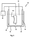
先に開示したように、本開示の方法により金属加工物から、蒸着された窒化物磨耗または離型被覆を電解剥離する工程は、陽極、陰極および電解質を含む電解槽に電流を流す工程を含み、被覆された加工物が槽の陽極を構成する。図3は、それらの方法により金型または他の加工物から窒化物離型被覆を剥離するのに適した電解槽50の説明図を示す。
As previously disclosed, the step of electrolytically stripping the deposited nitride wear or release coating from the metal workpiece by the method of the present disclosure includes passing a current through an electrolytic cell comprising an anode, a cathode and an electrolyte. The coated workpiece constitutes the tank anode. FIG. 3 shows an illustration of an
より詳しく図3を参照すると、槽の電解質52は、その中に被覆加工物すなわち陽極54が浸漬されるアルカリ水溶液からなる。槽の陰極は、水性アルカリ媒質中の電子供与体として働くときに、耐食性である金属から適切に形成される1つ以上の対電極56を含む。
Referring to FIG. 3 in more detail, the
この槽の動作において、電流が、加工物54からPCD施用されたTiAlN離型被覆54aと電解質52を通じて陰極の対電極56に向かって流される。この電流は、電源58による陽極と陰極に亘る比較的低電圧、例えば、1〜15ボルトの電圧の印加により生じ、この電源は、図面に示された極性またはバイアスで槽に接続されている。これらの電解槽の陰極(対電極56)は、例えば、白金、チタン、ニオブ、合金鋼およびニッケル・クロム合金から選択される金属から適切に構成されるが、必要な耐アルカリ腐食性を有する他の金属を代わりに使用しても差し支えない。図3の装置において、一対の超音波振動子60が設けられて、電解質溶液にエネルギーを与えているが、その使用は必須ではない。
In the operation of this vessel, a current is passed from the workpiece 54 through the
図6は、熱サイクルを全く経験しなかった堆積されたままのTiAlN被覆の電圧の関数としての電流のプロット(C−V)を示す。図6は、電子移動が約1.6Vから約1.8Vまで開始されないことを示している。この時点で、電流は、約3.5Vまで電圧の増加と共に線形に増加し、約3.5Vの時点で、別の電子移動反応が始まり、電流は電圧の関数として指数関数的に増加する。 FIG. 6 shows a plot of current (C-V) as a function of voltage for an as-deposited TiAlN coating that did not experience any thermal cycling. FIG. 6 shows that electron transfer is not initiated from about 1.6V to about 1.8V. At this point, the current increases linearly with increasing voltage to about 3.5V, at which point another electron transfer reaction begins and the current increases exponentially as a function of voltage.
これらの槽の特別な実施の形態において、使用されるアルカリ性電解質水溶液は、水酸化カリウムおよび水酸化ナトリウムからなる群より選択される化合物を少なくとも1種類含む。KOHまたはNaOHの濃度が1モル濃度から12モル濃度(1M〜12M)の範囲にあるアルカリ溶液は、上述した槽電圧で急激なエッチングを行うことができる。一例として、電解槽に亘り1Vから5Vの範囲、いくつかの実施の形態においては、約3Vから約5Vの範囲の電流生成電圧を印加することによって、効果的なTiAlN剥離を行うことができる。KOH溶液は、図7に示されように、これらの条件下で、NaOH溶液よりもいくぶん速くTiAlNを溶解させることが分かった。 In a special embodiment of these vessels, the alkaline electrolyte aqueous solution used contains at least one compound selected from the group consisting of potassium hydroxide and sodium hydroxide. An alkaline solution in which the concentration of KOH or NaOH is in the range of 1 molar concentration to 12 molar concentration (1M to 12M) can be etched rapidly with the above-described cell voltage. As an example, effective TiAlN stripping can be achieved by applying a current generating voltage in the range of 1V to 5V, and in some embodiments in the range of about 3V to about 5V across the cell. The KOH solution was found to dissolve TiAlN somewhat faster than the NaOH solution under these conditions, as shown in FIG.
残念ながら、上述したような熱サイクルの施されたTiAlN離型被覆の除去に極めて効果的な電解質剥離条件は、離型被覆を金属基体に結合するのに用いられるTiAl、Ti、Alなどの下にある中間層を除去するのには効果的ではない。熱サイクル中に金属基体から中間層にニッケル、クロムおよび/または鉄が拡散することによって生じる金属間材料は、図3に示されるような電解槽中で陽極としてバイアスがかけられたときに、酸化する傾向にあり、その酸化は電流を遮断し、それゆえ、中間層の溶解が妨げられる。 Unfortunately, electrolyte stripping conditions that are extremely effective in removing a heat cycled TiAlN release coating as described above are under the conditions of TiAl, Ti, Al, etc. used to bond the release coating to a metal substrate. It is not effective to remove the intermediate layer. The intermetallic material produced by the diffusion of nickel, chromium and / or iron from the metal substrate to the intermediate layer during thermal cycling is oxidized when biased as an anode in an electrolytic cell as shown in FIG. The oxidation cuts off the current and therefore prevents dissolution of the intermediate layer.
この問題を克服するのに効果的な本発明の方法の実施の形態は、離型槽の剥離後に、さらに別の処理工程を含む。その工程は、アルカリ性電解質水溶液中に浸漬されている間に、金型または他の加工物にバアイスまたは極性を反対にする電流パルスを通す工程を含む。この交流パルスにより、中間層の酸化とエッチングが交互に生じ、十分な時間に亘り継続されれば、中間層が実質的に完全に溶解する。 An embodiment of the method of the present invention that is effective in overcoming this problem includes further processing steps after stripping of the mold release tank. The process involves passing a current pulse that reverses baice or polarity through a mold or other workpiece while immersed in an aqueous alkaline electrolyte solution. This alternating pulse causes alternating oxidation and etching of the intermediate layer, and if continued for a sufficient time, the intermediate layer is substantially completely dissolved.
図4は、図3に示されたような装置において被覆金型を処理するときに、ニッケル・クロム合金製ガラス用金型の表面からのニッケル、クロムおよび鉄の群から選択される1種類以上の拡散金属混入物を含有するTiAl中間層を除去するのに効果的な交流パルスを導入するのに適した、印加DC電圧対時間のプロットである。等しい正と負のバイアス時間が図4に示されているが、正と負のバイアスの期間は、特定の場合におけるエッチング効率を改善するために、独立して調節することができる。しかしながら、効率的に中間層を溶解させるために、電解質溶液の組成を変える必要はなく、溶液の加熱も電圧の増加も必要ではないので、この工程を行うためのエネルギー要件は少ない。 FIG. 4 shows one or more selected from the group of nickel, chromium and iron from the surface of a nickel-chromium alloy glass mold when the coated mold is processed in the apparatus shown in FIG. FIG. 3 is a plot of applied DC voltage versus time suitable for introducing an AC pulse effective to remove a TiAl interlayer containing a number of diffused metal contaminants. Although equal positive and negative bias times are shown in FIG. 4, the duration of the positive and negative bias can be adjusted independently to improve etch efficiency in certain cases. However, in order to efficiently dissolve the intermediate layer, it is not necessary to change the composition of the electrolyte solution, and neither heating of the solution nor increasing voltage is required, so there are few energy requirements for performing this step.
先に記載した方法にしたがって、中間層を除去する難点が効果的に対処されるが、ある程度または完全な中間層の除去が必要ない場合がいくつかある。いくつかの場合には、代わりに、中間層の表面を単に再状態調節することによって、適切に蒸着された窒化物離型被覆の再結合を行っても差し支えない。再状態調節は、例えば、1〜3μmのグリットサイズを有するSiCサンドペーパーまたは0.5〜9μmの粒径範囲のアルミナ粒子の水性懸濁液を使用して、離型被覆の除去後に残る中間層の剥離面を研磨する工程によって行っても差し支えない。そのような方法の説明に役立つ例として、残留する中間層を、脱イオン水中の3μmのアルミナ粒子の分散液により接触研磨して、適切に剥離された金型表面品質を達成する。 Although the difficulty of removing the intermediate layer is effectively addressed according to the methods described above, there are some cases where some or complete removal of the intermediate layer is not necessary. In some cases, instead, it may be possible to recombine the properly deposited nitride release coating by simply reconditioning the surface of the intermediate layer. Reconditioning can be achieved by using, for example, an SiC sandpaper having a grit size of 1 to 3 μm or an aqueous suspension of alumina particles having a particle size range of 0.5 to 9 μm to leave the intermediate layer after removal of the release coating It may be performed by a process of polishing the peeled surface. As an illustrative example of such a method, the remaining intermediate layer is contact polished with a dispersion of 3 μm alumina particles in deionized water to achieve a properly exfoliated mold surface quality.
図3に示された装置は、開示された方法の実施にうまく適しているが、いくつかの場合には、装置の設計における変更により、経済的な利点が提示され得る。一例として、加工物および対電極が2つの別個の区画内にあり、これら2つの区画が塩橋により接続されている二室型電解槽により、対電極上に剥離された被覆材料が再堆積することによる二次汚染を最少にしながら、イオン伝導のために必要な経路を提供することができる。 Although the apparatus shown in FIG. 3 is well suited to performing the disclosed method, in some cases, changes in the design of the apparatus may present economic advantages. As an example, a two-chamber electrolytic cell in which the work piece and the counter electrode are in two separate compartments connected by a salt bridge redeposits the stripped coating material on the counter electrode. The necessary path for ionic conduction can be provided while minimizing the possible secondary contamination.
前述したように、ここに開示した方法は、金属製工具から磨耗または離型被覆を除去するための厳しい化学剥離手法の使用に勝る重大な利点を提示する。より少ない剥離溶液容積が効果的であり、要求される電圧および電流密度が適度であるので、電気化学剥離には、化学剥離よりも相当少ないプロセスエネルギーしか必要ない。また、剥離溶液の加熱はほとんどまたは全く必要ない。その上、プロセスの拡大は、複雑ではなく、大きい設備投資は必要ない。電解質浴の容積および対電極のサイズを適度に増加させることしか必要ない。最後に、開示した電気化学方法では、合金の表面を損傷し得、貯蔵と安全に取り扱うのが難しい、HFおよびH2O2などの化学物質を使用する必要をなくしつつ、総剥離時間が、例えば、数十時間から数十分まで、著しく減少する。 As previously mentioned, the method disclosed herein offers significant advantages over the use of rigorous chemical stripping techniques to remove wear or release coatings from metal tools. Electrochemical stripping requires significantly less process energy than chemical stripping because less stripping solution volume is effective and the required voltage and current density is reasonable. Also, little or no heating of the stripping solution is necessary. Moreover, the process expansion is not complicated and does not require a large capital investment. It is only necessary to moderately increase the volume of the electrolyte bath and the size of the counter electrode. Finally, the disclosed electrochemical method eliminates the need to use chemicals such as HF and H 2 O 2 that can damage the surface of the alloy and are difficult to store and handle safely, while the total stripping time is For example, it decreases significantly from several tens of hours to several tens of minutes.
本開示の方法を、特定の手法、材料、および装置に関して上述してきたが、それらの具体的に開示された実施の形態は、様々な適応および改変の単なる説明であり、それらは、付随の特許請求の範囲内の関連用途の要件を満たすように適応されることが当業者には明白であろう。 Although the methods of the present disclosure have been described above with respect to particular techniques, materials, and devices, those specifically disclosed embodiments are merely illustrative of various adaptations and modifications, and are not subject to the accompanying patents. It will be apparent to those skilled in the art that it is adapted to meet the requirements of the relevant application within the scope of the claims.
50 電解槽
52 電解質
54 加工物
54a TiAlN離型被覆
56 対電極
58 電源
60 超音波振動子
50
Claims (12)
前記離型被覆上の表面酸化層を破壊して、該離型被覆の導電率を増加させる工程、および
前記離型被覆上の表面酸化層を破壊して、前記離型被覆の導電率を増加させる工程に続けて、前記加工物、離型被覆および対電極がアルカリ性電解質水溶液中に浸漬されている間に、該加工物および離型被覆から該対電極に電流を流す工程、
を有してなる方法。 A method for stripping a partially oxidized nitride release coating from a metal workpiece,
Breaking the surface oxide layer on the release coating to increase the conductivity of the release coating; and
Following the step of destroying the surface oxide layer on the release coating and increasing the conductivity of the release coating, while the workpiece, the release coating and the counter electrode are immersed in the alkaline electrolyte aqueous solution Passing a current from the workpiece and the release coating to the counter electrode;
A method comprising:
Applications Claiming Priority (3)
| Application Number | Priority Date | Filing Date | Title |
|---|---|---|---|
| US32452610P | 2010-04-15 | 2010-04-15 | |
| US61/324,526 | 2010-04-15 | ||
| PCT/US2011/031874 WO2011130135A2 (en) | 2010-04-15 | 2011-04-11 | Method for stripping nitride coatings |
Publications (3)
| Publication Number | Publication Date |
|---|---|
| JP2013527317A JP2013527317A (en) | 2013-06-27 |
| JP2013527317A5 JP2013527317A5 (en) | 2014-05-29 |
| JP5997133B2 true JP5997133B2 (en) | 2016-09-28 |
Family
ID=44788541
Family Applications (1)
| Application Number | Title | Priority Date | Filing Date |
|---|---|---|---|
| JP2013504967A Expired - Fee Related JP5997133B2 (en) | 2010-04-15 | 2011-04-11 | Method for stripping nitride coating |
Country Status (6)
| Country | Link |
|---|---|
| US (1) | US9903040B2 (en) |
| EP (1) | EP2558621B1 (en) |
| JP (1) | JP5997133B2 (en) |
| KR (1) | KR101770012B1 (en) |
| TW (1) | TWI507573B (en) |
| WO (1) | WO2011130135A2 (en) |
Families Citing this family (10)
| Publication number | Priority date | Publication date | Assignee | Title |
|---|---|---|---|---|
| US8887532B2 (en) * | 2010-08-24 | 2014-11-18 | Corning Incorporated | Glass-forming tools and methods |
| US20130125590A1 (en) * | 2011-11-23 | 2013-05-23 | Jiangwei Feng | Reconditioning glass-forming molds |
| US9879356B2 (en) | 2014-03-18 | 2018-01-30 | Platit Ag | Method for delamination of ceramic hard material layers from steel and cemented carbide substrates |
| TW201739704A (en) | 2016-01-20 | 2017-11-16 | 康寧公司 | Molds with coatings for high temperature use in shaping glass-based material |
| TWI658506B (en) | 2016-07-13 | 2019-05-01 | 美商英奧創公司 | Electrochemical methods, devices and compositions |
| CN107815638B (en) * | 2017-11-07 | 2019-07-12 | 福建工程学院 | A kind of AlTiCrCN nano-hard coating containing multi-layer structure and preparation method thereof |
| WO2020039011A1 (en) * | 2018-08-21 | 2020-02-27 | Oerlikon Surface Solutions Ag, Pfäffikon | Stripping of coatings al-containing coatings |
| CN111621841B (en) * | 2020-05-21 | 2022-05-10 | 南京理工大学 | A kind of electrolytic polishing solution based on TiAl single crystal EBSD sample and its electrolytic method |
| CN112008501B (en) * | 2020-08-14 | 2021-10-29 | 苏州珂玛材料科技股份有限公司 | Method for improving aluminum nitride ceramic grinding surface flatness |
| CN113073293B (en) * | 2021-03-11 | 2023-01-03 | 南通大学 | Structure and method for improving tribological performance of E690 steel |
Family Cites Families (21)
| Publication number | Priority date | Publication date | Assignee | Title |
|---|---|---|---|---|
| US3554881A (en) * | 1966-04-23 | 1971-01-12 | Roberto Piontelli | Electrochemical process for the surface treatment of titanium,alloys thereof and other analogous metals |
| US4747864A (en) * | 1986-06-19 | 1988-05-31 | Corning Glass Works | Process for the precision molding of glass articles |
| DD295879A5 (en) * | 1988-03-31 | 1991-11-14 | Rathenower Optische Werke Gmbh,De | PROCESS FOR UNLOADING TITANIC BODY AND TITANIUM DRY LAYERS |
| JPH059743A (en) * | 1991-06-27 | 1993-01-19 | Aichi Steel Works Ltd | Method of electroless ni plating on al and al alloy |
| JP3320965B2 (en) * | 1995-03-29 | 2002-09-03 | エムエムシーコベルコツール株式会社 | Hard film peeling method and recoated member obtained by the method |
| JP3678295B2 (en) * | 1995-04-27 | 2005-08-03 | 日立金属株式会社 | Steel surface cleaning method and steel material |
| JPH09301722A (en) * | 1996-05-14 | 1997-11-25 | Fuji Photo Optical Co Ltd | Formation of release film |
| TW591125B (en) * | 1998-02-13 | 2004-06-11 | Mitsubishi Heavy Ind Ltd | Method and apparatus for removing Ti-derived film |
| JP2000044259A (en) * | 1998-07-22 | 2000-02-15 | Olympus Optical Co Ltd | Optical element forming method |
| JP2000319028A (en) * | 1999-04-30 | 2000-11-21 | Canon Inc | Method for regenerating glass optical element press forming die |
| JP2004035359A (en) * | 2002-07-05 | 2004-02-05 | Pentax Corp | Method for regenerating protective film of mold for molding optical element |
| US6969457B2 (en) * | 2002-10-21 | 2005-11-29 | General Electric Company | Method for partially stripping a coating from the surface of a substrate, and related articles and compositions |
| US7077918B2 (en) | 2004-01-29 | 2006-07-18 | Unaxis Balzers Ltd. | Stripping apparatus and method for removal of coatings on metal surfaces |
| JP4905131B2 (en) * | 2004-05-27 | 2012-03-28 | コニカミノルタオプト株式会社 | Optical element forming mold, method for producing the same and method for reproducing the same |
| US7867633B2 (en) * | 2004-06-07 | 2011-01-11 | Colorado School Of Mines | Coatings for glass molding dies and forming tools |
| JP4463656B2 (en) | 2004-10-15 | 2010-05-19 | 住友重機械工業株式会社 | Reproduction method of mold for molding |
| JP4403286B2 (en) * | 2005-03-15 | 2010-01-27 | 株式会社片桐製作所 | Cemented carbide tool material and manufacturing method thereof |
| US20060226025A1 (en) * | 2005-03-16 | 2006-10-12 | Colorado School Of Mines | Electrochemical removal of die coatings |
| US20070186589A1 (en) * | 2006-02-10 | 2007-08-16 | Ether Precision, Inc. | Mold for press-molding glass elements |
| KR101073414B1 (en) | 2006-04-10 | 2011-10-17 | 오에스지 가부시키가이샤 | Method of removing hard coating film |
| US8361290B2 (en) * | 2006-09-05 | 2013-01-29 | Oerlikon Trading, Ag, Trubbach | Coating removal installation and method of operating it |
-
2011
- 2011-04-07 TW TW100111921A patent/TWI507573B/en not_active IP Right Cessation
- 2011-04-11 JP JP2013504967A patent/JP5997133B2/en not_active Expired - Fee Related
- 2011-04-11 EP EP11715816.2A patent/EP2558621B1/en not_active Not-in-force
- 2011-04-11 KR KR1020127029640A patent/KR101770012B1/en active IP Right Grant
- 2011-04-11 WO PCT/US2011/031874 patent/WO2011130135A2/en active Application Filing
- 2011-04-12 US US13/084,802 patent/US9903040B2/en not_active Expired - Fee Related
Also Published As
| Publication number | Publication date |
|---|---|
| WO2011130135A2 (en) | 2011-10-20 |
| TW201207163A (en) | 2012-02-16 |
| WO2011130135A3 (en) | 2012-12-27 |
| US20110256807A1 (en) | 2011-10-20 |
| JP2013527317A (en) | 2013-06-27 |
| TWI507573B (en) | 2015-11-11 |
| US9903040B2 (en) | 2018-02-27 |
| EP2558621A2 (en) | 2013-02-20 |
| EP2558621B1 (en) | 2017-06-14 |
| KR20130051445A (en) | 2013-05-20 |
| KR101770012B1 (en) | 2017-08-21 |
Similar Documents
| Publication | Publication Date | Title |
|---|---|---|
| JP5997133B2 (en) | Method for stripping nitride coating | |
| JP4541683B2 (en) | Method for partially stripping a coating film from the surface of a substrate, articles and compositions related thereto | |
| Anasane et al. | Experimental investigation on suitability of electrolytes for electrochemical micromachining of titanium | |
| JP3404286B2 (en) | Metal surface treatment method, and metal member having a surface obtained by the surface treatment method | |
| EP3359712B1 (en) | Smoothing the surface finish of rough metal articles | |
| JP2005240074A (en) | Electrically conductive diamond electrode and its production method | |
| JP7531517B2 (en) | Electrolytic Polishing Method | |
| CN104120460A (en) | Method for removing scaling of surface of titanium anode for electrolytic copper foil | |
| NO335744B1 (en) | Electrode characterized by a highly adhesive catalytic layer on the surface | |
| US20060226025A1 (en) | Electrochemical removal of die coatings | |
| JP2599629B2 (en) | Electrolysis method and bath for stripping coating from aluminum substrate | |
| CN114855105A (en) | Pretreatment method of titanium anode base material | |
| CN103603026B (en) | A kind of method taken off completely except workpiece surface diamond-like carbon film | |
| CA2031454A1 (en) | Molten salt stripping of electrode coatings | |
| US20080277288A1 (en) | Method For Removing A Coating From A Component | |
| KR101846940B1 (en) | Forming method of protective coating for aluminum containing article | |
| CN100422390C (en) | Differential arc oxidization abrasive polishing method for stainless steel surface | |
| CN102899667A (en) | Application of aqueous solution of ammonium bifluoride in de-plating of PVD decorative film | |
| JP4001202B2 (en) | Electrolytic peeling method by high-speed polarity reversal | |
| JP2005506457A (en) | Electrolytic method and composition for stripping electroless nickel | |
| JP6041915B2 (en) | Surface treatment method for aluminum and aluminum alloy and electrolytic solution used for the surface treatment method | |
| CA1176600A (en) | Removal of electrocatalytic coating from electrodes by formation of a non-adhesive intermediate layer | |
| JPS5919991B2 (en) | Two-stage pickling method for pure silicon steel materials | |
| RU2339738C1 (en) | Method for heat-resistant coating removal from parts of heat-stable nickel alloys | |
| TWI248480B (en) | Method for producing corrosion protective coatings on light metal alloys |
Legal Events
| Date | Code | Title | Description |
|---|---|---|---|
| A521 | Request for written amendment filed |
Free format text: JAPANESE INTERMEDIATE CODE: A523 Effective date: 20140408 |
|
| A621 | Written request for application examination |
Free format text: JAPANESE INTERMEDIATE CODE: A621 Effective date: 20140408 |
|
| A977 | Report on retrieval |
Free format text: JAPANESE INTERMEDIATE CODE: A971007 Effective date: 20150128 |
|
| A131 | Notification of reasons for refusal |
Free format text: JAPANESE INTERMEDIATE CODE: A131 Effective date: 20150203 |
|
| A521 | Request for written amendment filed |
Free format text: JAPANESE INTERMEDIATE CODE: A523 Effective date: 20150507 |
|
| A131 | Notification of reasons for refusal |
Free format text: JAPANESE INTERMEDIATE CODE: A131 Effective date: 20151020 |
|
| A601 | Written request for extension of time |
Free format text: JAPANESE INTERMEDIATE CODE: A601 Effective date: 20160120 |
|
| A521 | Request for written amendment filed |
Free format text: JAPANESE INTERMEDIATE CODE: A523 Effective date: 20160222 |
|
| TRDD | Decision of grant or rejection written | ||
| A01 | Written decision to grant a patent or to grant a registration (utility model) |
Free format text: JAPANESE INTERMEDIATE CODE: A01 Effective date: 20160802 |
|
| A61 | First payment of annual fees (during grant procedure) |
Free format text: JAPANESE INTERMEDIATE CODE: A61 Effective date: 20160825 |
|
| R150 | Certificate of patent or registration of utility model |
Ref document number: 5997133 Country of ref document: JP Free format text: JAPANESE INTERMEDIATE CODE: R150 |
|
| R250 | Receipt of annual fees |
Free format text: JAPANESE INTERMEDIATE CODE: R250 |
|
| R250 | Receipt of annual fees |
Free format text: JAPANESE INTERMEDIATE CODE: R250 |
|
| LAPS | Cancellation because of no payment of annual fees |