JP5984936B2 - 離間したクランプ部をもつクランプ穴を有する切削工具および切削インサート - Google Patents
離間したクランプ部をもつクランプ穴を有する切削工具および切削インサート Download PDFInfo
- Publication number
- JP5984936B2 JP5984936B2 JP2014526599A JP2014526599A JP5984936B2 JP 5984936 B2 JP5984936 B2 JP 5984936B2 JP 2014526599 A JP2014526599 A JP 2014526599A JP 2014526599 A JP2014526599 A JP 2014526599A JP 5984936 B2 JP5984936 B2 JP 5984936B2
- Authority
- JP
- Japan
- Prior art keywords
- clamp
- central axis
- horizontal plane
- cutting
- vertical
- Prior art date
- Legal status (The legal status is an assumption and is not a legal conclusion. Google has not performed a legal analysis and makes no representation as to the accuracy of the status listed.)
- Active
Links
- 238000005520 cutting process Methods 0.000 title claims description 150
- 230000002093 peripheral effect Effects 0.000 claims description 16
- 230000001154 acute effect Effects 0.000 claims description 14
- 238000003801 milling Methods 0.000 description 10
- 239000013598 vector Substances 0.000 description 3
- 239000000463 material Substances 0.000 description 2
- 229910052751 metal Inorganic materials 0.000 description 2
- 239000002184 metal Substances 0.000 description 2
- 241001481760 Erethizon dorsatum Species 0.000 description 1
- 229910000831 Steel Inorganic materials 0.000 description 1
- 230000002427 irreversible effect Effects 0.000 description 1
- 230000013011 mating Effects 0.000 description 1
- 150000001247 metal acetylides Chemical class 0.000 description 1
- 238000012986 modification Methods 0.000 description 1
- 230000004048 modification Effects 0.000 description 1
- 230000002441 reversible effect Effects 0.000 description 1
- 239000010959 steel Substances 0.000 description 1
- UONOETXJSWQNOL-UHFFFAOYSA-N tungsten carbide Chemical compound [W+]#[C-] UONOETXJSWQNOL-UHFFFAOYSA-N 0.000 description 1
Images


Classifications
-
- B—PERFORMING OPERATIONS; TRANSPORTING
- B23—MACHINE TOOLS; METAL-WORKING NOT OTHERWISE PROVIDED FOR
- B23C—MILLING
- B23C5/00—Milling-cutters
- B23C5/02—Milling-cutters characterised by the shape of the cutter
- B23C5/08—Disc-type cutters
-
- B—PERFORMING OPERATIONS; TRANSPORTING
- B23—MACHINE TOOLS; METAL-WORKING NOT OTHERWISE PROVIDED FOR
- B23C—MILLING
- B23C5/00—Milling-cutters
- B23C5/02—Milling-cutters characterised by the shape of the cutter
- B23C5/06—Face-milling cutters, i.e. having only or primarily a substantially flat cutting surface
-
- B—PERFORMING OPERATIONS; TRANSPORTING
- B23—MACHINE TOOLS; METAL-WORKING NOT OTHERWISE PROVIDED FOR
- B23C—MILLING
- B23C5/00—Milling-cutters
- B23C5/16—Milling-cutters characterised by physical features other than shape
- B23C5/20—Milling-cutters characterised by physical features other than shape with removable cutter bits or teeth or cutting inserts
- B23C5/22—Securing arrangements for bits or teeth or cutting inserts
- B23C5/2204—Securing arrangements for bits or teeth or cutting inserts with cutting inserts clamped against the walls of the recess in the cutter body by a clamping member acting upon the wall of a hole in the insert
- B23C5/2208—Securing arrangements for bits or teeth or cutting inserts with cutting inserts clamped against the walls of the recess in the cutter body by a clamping member acting upon the wall of a hole in the insert for plate-like cutting inserts
- B23C5/2213—Securing arrangements for bits or teeth or cutting inserts with cutting inserts clamped against the walls of the recess in the cutter body by a clamping member acting upon the wall of a hole in the insert for plate-like cutting inserts having a special shape
-
- B—PERFORMING OPERATIONS; TRANSPORTING
- B23—MACHINE TOOLS; METAL-WORKING NOT OTHERWISE PROVIDED FOR
- B23C—MILLING
- B23C2200/00—Details of milling cutting inserts
- B23C2200/08—Rake or top surfaces
- B23C2200/085—Rake or top surfaces discontinuous
-
- B—PERFORMING OPERATIONS; TRANSPORTING
- B23—MACHINE TOOLS; METAL-WORKING NOT OTHERWISE PROVIDED FOR
- B23C—MILLING
- B23C2200/00—Details of milling cutting inserts
- B23C2200/28—Angles
- B23C2200/286—Positive cutting angles
-
- B—PERFORMING OPERATIONS; TRANSPORTING
- B23—MACHINE TOOLS; METAL-WORKING NOT OTHERWISE PROVIDED FOR
- B23C—MILLING
- B23C2200/00—Details of milling cutting inserts
- B23C2200/28—Angles
- B23C2200/287—Positive rake angles
-
- B—PERFORMING OPERATIONS; TRANSPORTING
- B23—MACHINE TOOLS; METAL-WORKING NOT OTHERWISE PROVIDED FOR
- B23C—MILLING
- B23C2200/00—Details of milling cutting inserts
- B23C2200/36—Other features of the milling insert not covered by B23C2200/04 - B23C2200/32
- B23C2200/361—Fixation holes
-
- B—PERFORMING OPERATIONS; TRANSPORTING
- B23—MACHINE TOOLS; METAL-WORKING NOT OTHERWISE PROVIDED FOR
- B23C—MILLING
- B23C2210/00—Details of milling cutters
- B23C2210/16—Fixation of inserts or cutting bits in the tool
- B23C2210/168—Seats for cutting inserts, supports for replacable cutting bits
-
- Y—GENERAL TAGGING OF NEW TECHNOLOGICAL DEVELOPMENTS; GENERAL TAGGING OF CROSS-SECTIONAL TECHNOLOGIES SPANNING OVER SEVERAL SECTIONS OF THE IPC; TECHNICAL SUBJECTS COVERED BY FORMER USPC CROSS-REFERENCE ART COLLECTIONS [XRACs] AND DIGESTS
- Y10—TECHNICAL SUBJECTS COVERED BY FORMER USPC
- Y10T—TECHNICAL SUBJECTS COVERED BY FORMER US CLASSIFICATION
- Y10T407/00—Cutters, for shaping
- Y10T407/19—Rotary cutting tool
- Y10T407/1906—Rotary cutting tool including holder [i.e., head] having seat for inserted tool
- Y10T407/1934—Rotary cutting tool including holder [i.e., head] having seat for inserted tool with separate means to fasten tool to holder
- Y10T407/1936—Apertured tool
-
- Y—GENERAL TAGGING OF NEW TECHNOLOGICAL DEVELOPMENTS; GENERAL TAGGING OF CROSS-SECTIONAL TECHNOLOGIES SPANNING OVER SEVERAL SECTIONS OF THE IPC; TECHNICAL SUBJECTS COVERED BY FORMER USPC CROSS-REFERENCE ART COLLECTIONS [XRACs] AND DIGESTS
- Y10—TECHNICAL SUBJECTS COVERED BY FORMER USPC
- Y10T—TECHNICAL SUBJECTS COVERED BY FORMER US CLASSIFICATION
- Y10T407/00—Cutters, for shaping
- Y10T407/22—Cutters, for shaping including holder having seat for inserted tool
- Y10T407/2272—Cutters, for shaping including holder having seat for inserted tool with separate means to fasten tool to holder
- Y10T407/2274—Apertured tool
-
- Y—GENERAL TAGGING OF NEW TECHNOLOGICAL DEVELOPMENTS; GENERAL TAGGING OF CROSS-SECTIONAL TECHNOLOGIES SPANNING OVER SEVERAL SECTIONS OF THE IPC; TECHNICAL SUBJECTS COVERED BY FORMER USPC CROSS-REFERENCE ART COLLECTIONS [XRACs] AND DIGESTS
- Y10—TECHNICAL SUBJECTS COVERED BY FORMER USPC
- Y10T—TECHNICAL SUBJECTS COVERED BY FORMER US CLASSIFICATION
- Y10T407/00—Cutters, for shaping
- Y10T407/23—Cutters, for shaping including tool having plural alternatively usable cutting edges
Landscapes
- Engineering & Computer Science (AREA)
- Mechanical Engineering (AREA)
- Cutting Tools, Boring Holders, And Turrets (AREA)
- Milling Processes (AREA)
- Harvester Elements (AREA)
Description
前記少なくとも1つの切削インサートが、外周側面および中心軸が間に延びる対向する上面および底面と、前記上面のクランプ穴とを備え、
前記外周側面が少なくとも1つのフランク面を備え、少なくとも1つの切刃が、前記少なくとも1つのフランク面と少なくとも前記上面との交差部に形成され、
前記クランプ穴が、第1の水平面に交差する少なくとも2つの上部クランプ部と、第2の水平面に交差する少なくとも2つの下部クランプ部とを備え、前記クランプ部のそれぞれが前記クランプ穴の異なる領域を表し、前記第1の水平面および前記第2の水平面が、前記中心軸に垂直であって互いに離間し、
前記少なくとも2つの上部クランプ部に対して接線であり、前記中心軸と同一平面上にある上部仮想線が、前記中心軸と共にゼロまたは鋭角の第1のクランプ角を形成し、前記少なくとも2つの下部クランプ部に対して接線であり、前記中心軸と同一平面上にある下部仮想線が、前記中心軸と共にゼロまたは鋭角の第2のクランプ角を形成し、
前記第1のクランプ角と前記第2のクランプ角とが異なり、
4つの作動クランプ部を表すちょうど2つの上部クランプ部とちょうど2つの下部クランプ部とが、前記締結部材上の同数の対応するクランプゾーンに同時にクランプ接触することを特徴とする切削工具が提供される。
前記外周側面が少なくとも1つのフランク面を備え、少なくとも1つの切刃が、前記少なくとも1つのフランク面と少なくとも前記上面との交差部に形成され、
前記クランプ穴が、第1の水平面に交差する少なくとも2つの上部クランプ部と、第2の水平面に交差する少なくとも2つの下部クランプ部とを備え、前記クランプ部のそれぞれが前記クランプ穴の異なる領域を表し、前記第1の水平面および前記第2の水平面が、前記中心軸に垂直であって互いに離間し、
前記少なくとも2つの上部クランプ部に対して接線であり、前記中心軸と同一平面上にある上部仮想線が、前記中心軸と共にゼロまたは鋭角の第1のクランプ角を形成し、前記少なくとも2つの下部クランプ部に対して接線であり、前記中心軸と同一平面上にある下部仮想線が、前記中心軸と共にゼロまたは鋭角の第2のクランプ角を形成し、
前記第1のクランプ角と前記第2のクランプ角とが異なり、
前記クランプ穴が、前記底面に向かって延びて前記底面で開き、前記第1の水平面および前記第2の水平面に沿った横断面において非円形であり、
前記上部および下部仮想線が、前記中心軸に交差せずに前記上面より上の方向に延びることを特徴とする切削インサートが提供される。
前記外周側面が少なくとも1つのフランク面を備え、少なくとも1つの切刃が、前記少なくとも1つのフランク面と少なくとも前記上面との交差部に形成され、
前記クランプ穴が、第1の水平面に交差する少なくとも2つの上部クランプ部と、第2の水平面に交差する少なくとも2つの下部クランプ部とを備え、前記クランプ部のそれぞれが前記クランプ穴の異なる領域を表し、前記第1の水平面および前記第2の水平面が、前記中心軸に垂直であって互いに離間し、
前記クランプ穴が前記底面に向かって開き、前記第1の水平面および前記第2の水平面に沿った横断面において非円形であり、
前記少なくとも2つの上部クランプ部および前記少なくとも2つの下部クランプ部が、前記中心軸を含む、前記少なくとも1つのフランク面に垂直な垂直面に対して対称であり、
前記少なくとも2つの上部クランプ部および前記少なくとも2つの下部クランプ部が、前記インサート中心軸に沿った前記インサートの上面図において前記クランプ穴内に見えることを特徴とする切削インサートが提供される。
Claims (18)
- 少なくとも1つの着座面(24)を有する工具本体(22)と、少なくとも1つの切削インサート(26、126)と、前記少なくとも1つの切削インサート(26、126)を前記少なくとも1つの着座面(24)に取外し可能に固定するための少なくとも1つの締結部材(28)とを備えた切削工具(20、120)であって、
前記少なくとも1つの切削インサート(26、126)が、外周側面(36)および中心軸(A1)が間に延びる対向する上面(32)および底面(34)と、前記上面(32)にクランプ穴(38)とを備え、
前記外周側面(36)が少なくとも1つのフランク面(40)を備え、少なくとも1つの切刃(42)が、前記少なくとも1つのフランク面(40)と少なくとも前記上面(32)との交差部に形成され、
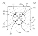
前記クランプ穴(38)が、周方向に互いに離間しており、第1の水平面(PH1)に交差する少なくとも2つの上部クランプ部(UC1、UC2)と、周方向に互いに離間しており、第2の水平面(PH2)に交差する少なくとも2つの下部クランプ部(LC1、LC2)とを備え、前記クランプ部(UC1、UC2、LC1、LC2)のそれぞれが前記クランプ穴(38)の異なる領域を表し、前記第1の水平面(PH1)および前記第2の水平面(PH2)が、前記中心軸(A1)に垂直であって互いに離間し、
前記少なくとも2つの上部クランプ部(UC1、UC2)に対して接線であり、前記中心軸(A1)と同一平面上にある上部仮想線(LU1、LU2)が、前記中心軸(A1)と共にゼロまたは鋭角の第1のクランプ角(αl)を形成し、前記少なくとも2つの下部クランプ部(LC1、LC2)に対して接線であり、前記中心軸(A1)と同一平面上にある下部仮想線(LL1、LL2)が、前記中心軸(A1)と共にゼロまたは鋭角の第2のクランプ角(α2)を形成し、
前記第1のクランプ角(α1)と前記第2のクランプ角(α2)とが異なり、
4つの作動クランプ部(UC1、UC2、LC1、LC2)を表すちょうど2つの上部クランプ部(UC1、UC2)とちょうど2つの下部クランプ部(LC1、LC2)とは、前記締結部材(28)上の同数の対応するクランプゾーン(UZ1、UZ2、LZ1、LZ2)に同時にクランプ接触し、前記クランプ穴(38)と前記締結部材(28)との間の他のクランプ接触点または領域がないことを特徴とする切削工具(20、120)。 - 前記第1の水平面(PH1)は前記少なくとも2つの上部クランプ部(UC1、UC2)を二分し、前記第2の水平面(PH2)は前記少なくとも2つの下部クランプ部(LC1、LC2)二分し、
前記第1の水平面(PH1)は前記第2の水平面(PH2)よりも前記上面(32)に近く、前記第1のクランプ角(α1)は前記第2のクランプ角(α2)よりも大きいことを特徴とする請求項1に記載の切削工具(20、120)。 - 前記4個の作動可能クランプ部(UC1、UC2、LC1、LC2)に関連する前記上部および下部仮想線(LU1、LU2、LL1、LL2)は、前記上面(32)上で前記中心軸(A1)に交差しないことを特徴とする請求項1に記載の切削工具(20、120)。
- 前記4個の作動可能クランプ部のうちの2個(UC1、LC1)に関連する上部および下部仮想線(LU1、LL1)は第1の垂直面(PV1)内に含まれ、前記4個の作動可能クランプ部のうちの他の2個(UC2、LC2)に関連する上部および下部仮想線(LU2、LL2)は第2の垂直面(PV2)内に含まれ、
前記第1の垂直面(PV1)は前記第2の垂直面(PV2)に垂直であり、
前記第1の垂直面(PV1)および前記第2の垂直面(PV2)は前記中心軸(A1)を含むことを特徴とする請求項1に記載の切削工具(20、120)。 - 前記少なくとも1つのフランク面(40)のそれぞれは、少なくとも1つの当接部(62)を備え、
単一フランク面(40)に関連する前記少なくとも1つの当接部(62)のみが動作可能であり、前記工具本体(22)上の対応する支持面(64)に当接し、
前記中心軸(A1)を含む第3の垂直面(PV3)は前記第1の垂直面(PV1)および前記第2の垂直面(PV2)を二分し、
前記単一作動可能フランク面(40)に関連する前記少なくとも1つの当接部(62)に接する当接面(PA1)は前記第3の垂直面(PV3)に垂直であることを特徴とする請求項4に記載の切削工具(20、120)。 - 前記クランプ穴(38)は前記底面(34)に向かって延びて前記底面(34)で開き、前記第1の水平面(PH1)および前記第2の水平面(PH2)に沿った横断面において非円形であり、
前記締結部材(28)は、ねじ軸(A2)を有するクランプねじ(44)の形状であることを特徴とする請求項1に記載の切削工具(20、120)。 - 外周側面(36)および中心軸(A1)が間に延びる対向する上面(32)および底面(34)と、前記上面(32)のクランプ穴(38)とを備えた切削インサート(26、126)であって、
前記外周側面(36)が少なくとも1つのフランク面(40)を備え、少なくとも1つの切刃(42)が、前記少なくとも1つのフランク面(40)と少なくとも前記上面(32)との交差部に形成され、
前記クランプ穴(38)が、第1の水平面(PH1)に交差する少なくとも2つの上部クランプ部(UC1、UC2)と、第2の水平面(PH2)に交差する少なくとも2つの下部クランプ部(LC1、LC2)とを備え、前記クランプ部(UC1、UC2、LC1、LC2)のそれぞれが前記クランプ穴(38)の異なる領域を表し、前記第1の水平面(PH1)および前記第2の水平面(PH2)が、前記中心軸(A1)に垂直であって互いに離間し、
前記少なくとも2つの上部クランプ部(UC1、UC2)に対して接線であり、前記中心軸(A1)と同一平面上にある上部仮想線(LU1、LU2)が、前記中心軸(A1)と共に鋭角の第1のクランプ角(α1)を形成し、前記少なくとも2つの下部クランプ部(LC1、LC2)に対して接線であり、前記中心軸(A1)と同一平面上にある下部仮想線(LL1、LL2)が、前記中心軸(A1)と共に鋭角の第2のクランプ角(α2)を形成し、
前記第1のクランプ角(α1)と前記第2のクランプ角(α2)とが異なり、
前記クランプ穴(38)が、前記底面(34)に向かって延びて前記底面(34)で開き、前記第1の水平面(PH1)および前記第2の水平面(PH2)に沿った横断面において非円形であり、
前記クランプ穴(38)は前記中心軸(A1)に垂直な正中面(M)に対して鏡面対称を呈し、少なくとも1つの切刃(42)は前記少なくとも1つのフランク面(40)と前記底面(34)との交差部に形成されることを特徴とする切削インサート(26、126)。 - 前記第1の水平面(PH1)は前記少なくとも2つの上部クランプ部(UC1、UC2)を二分し、前記第2の水平面(PH2)は前記少なくとも2つの下部クランプ部(LC1、LC2)を二分し、
前記第1の水平面(PH1)は前記第2の水平面(PH2)よりも前記上面(32)に近く、前記第1のクランプ角(α1)は前記第2のクランプ角(α2)よりも大きいことを特徴とする請求項7に記載の切削インサート(26、126)。 - 前記切削インサート(26、126)は、前記中心軸(A1)の周りで割出し可能であり、4個のフランク面(40)と、前記4個のフランク面(40)と前記上面(32)との交差部に形成された4個の切刃(42)と、4個の上部クランプ部(UC1、UC2、UC3、UC4)と、4個の下部クランプ部(LC1、LC2、LC3、LC4)とを有することを特徴とする請求項7に記載の切削インサート(26、126)。
- 前記4個の上部および下部クランプ部のうちの第1のクランプ部および第3のクランプ部(UC1、LC1、UC3、LC3)に関連する第1の上部および下部仮想線(LU1、LL1)と第3の上部および下部仮想線(LU3、LL3)とは、第1の垂直面(PV1)内に含まれ、前記4個の上部および下部クランプ部のうちの第2のクランプ部および第4のクランプ部(UC2、LC2、UC4、LC4)に関連する第2の上部および下部仮想線(LU2、LL2)と第4の上部および下部仮想線(LU4、LL4)とは、第2の垂直面(PV2)内に含まれ、
前記第1の垂直面(PV1)は前記第2の垂直面(PV2)に垂直であり、
前記第1の垂直面(PV1)および第2の垂直面(PV2)は前記中心軸(A1)を含むことを特徴とする請求項9に記載の切削インサート(26、126)。 - 前記4個のフランク面(40)のそれぞれは少なくとも1つの当接部(62)を備え、
第1のフランク面(40a)および第3のフランク面(40c)上のそれぞれの前記少なくとも1つの当接部(62)の1つに接する第1の当接面(PA1)および第3の当接面(PA3)は第3の垂直面(PV3)に垂直であり、第2のフランク面(40b)および第4のフランク面(40d)上のそれぞれの前記少なくとも1つの当接部(62)の1つに接する第2の当接面(PA2)および第4の当接面(PA4)は第4の垂直面(PV4)に垂直であり、
前記第3の垂直面(PV3)は前記第1の垂直面(PV1)および前記第2の垂直面(PV2)を二分し、前記第4の垂直面(PV4)は前記第3の垂直面(PV3)に垂直であることを特徴とする請求項10に記載の切削インサート(26、126)。 - 前記上部および下部仮想線(LU1、LU2、LL1、LL2)は、前記上面(32)上で前記中心軸(A1)に交差しないことを特徴とする請求項7に記載の切削インサート(126)。
- 前記第1の水平面(PH1)および前記第2の水平面(PH2)は前記上面(32)と前記正中面(M)との間に位置することを特徴とする請求項7に記載の切削インサート(126)。
- 外周側面(36)および中心軸(A1)が間に延びる対向する上面(32)および底面(34)と、前記底面(34)まで延びる前記上面(32)のクランプ穴(38)とを備えた切削インサート(26、126)であって、
前記外周側面(36)が少なくとも1つのフランク面(40)を備え、少なくとも1つの切刃(42)が、前記少なくとも1つのフランク面(40)と少なくとも前記上面(32)との交差部に形成され、
前記クランプ穴(38)が、第1の水平面(PH1)に交差する少なくとも2つの上部クランプ部(UC1、UC2)と、第2の水平面(PH2)に交差する少なくとも2つの下部クランプ部(LC1、LC2)とを備え、前記クランプ部(UC1、UC2、LC1、LC2)のそれぞれが前記クランプ穴(38)の異なる領域を表し、前記第1の水平面(PH1)および前記第2の水平面(PH2)が、前記中心軸(A1)に垂直であって互いに離間し、
前記クランプ穴(38)が前記底面(34)に向かって開き、前記第1の水平面(PH1)および前記第2の水平面(PH2)に沿った横断面において非円形であり、
前記少なくとも2つの上部クランプ部(UC1、UC2)および前記少なくとも2つの下部クランプ部(LC1、LC2)が、前記中心軸(A1)を含む、前記少なくとも1つのフランク面(40)に垂直な垂直面(PV3)に対して対称であり、
前記少なくとも2つの上部クランプ部(UC1、UC2)および前記少なくとも2つの下部クランプ部(LC1、LC2)が、前記インサート中心軸(A1)に沿った前記インサートの上面視において前記クランプ穴(38)内に見え、
前記少なくとも2つの上部クランプ部(UC1、UC2)のそれぞれと、前記少なくとも2つの下部クランプ部(LC1、LC2)のそれぞれとは、前記第1の水平面(PH1)および前記第2の水平面(PH2)のそれぞれに沿った横断面において別個の上部曲線(58)および下部曲線(60)の単一の弧として現れ、
前記上部曲線(58)および前記下部曲線(60)のそれぞれの曲率半径(R1、R2)は、前記第1の水平面(PH1)および前記第2の水平面(PH2)のそれぞれに沿った前記クランプ穴(38)の横断面における内接円の対応する曲率半径(R3、R4)よりも大きいことを特徴とする切削インサート(26、126)。 - 前記上部曲線(58)および前記下部曲線(60)はそれぞれ、前記中心軸(A1)を中心に曲率半径(Rl、R2)を有することを特徴とする請求項14に記載の切削インサート(26、126)。
- 前記少なくとも2つの上部クランプ部(UC1、UC2)に対して接線であり、前記中心軸(A1)と同一平面上にある上部仮想線(LU1、LU2)は、前記中心軸(A1)と共に鋭角の第1のクランプ角(αl)を形成し、前記少なくとも2つの下部クランプ部(LC1、LC2)に対して接線であり、前記中心軸(A1)と同一平面上にある下部仮想線(LL1、LL2)は、前記中心軸(A1)と共に鋭角の第2のクランプ角(α2)を形成し、
前記第1のクランプ角(α1)と第2のクランプ角(α2)とは異なり、
前記上部および下部仮想線(LU1、LU2、LL1、LL2)が、前記上面(32)上で前記中心軸(A1)に交差しないことを特徴とする請求項14に記載の切削インサート(26、126)。 - 前記切削インサート(26、126)は、前記中心軸(A1)の周りで割出し可能であり、4個のフランク面(40)と、前記4個のフランク面(40)と前記上面(32)との交差部に形成された4個の切刃(42)と、4個の上部クランプ部(UC1、UC2、UC3、UC4)と、4個の下部クランプ部(LC1、LC2、LC3、LC4)とを有し、
前記4個の上部および下部クランプ部(UC1、LC1、UC3、LC3)のうちの第1番目と第3番目に関連する、第1および第3上部および下部仮想線(LU1、LL1、LU3、LL3)は、第1の垂直面(PV1)内に含まれ、前記4個の上部および下部クランプ部のうちの第2番目と第4番目(UC2、LC2、UC4、LC4)に関連する、第2および第4上部および下部仮想線(LU2、LL2、LU4、LL4)は第2の垂直面(PV2)内に含まれ、
前記第1の垂直面(PV1)は前記第2の垂直面(PV2)に垂直であり、
前記第1および第2の垂直面(PV1、PV2)は、前記中心軸(A1)を含み、
前記4個のフランク面(40)のそれぞれは少なくとも1つの当接部(62)を備え、
第1および第3のフランク面(40a、40c)の前記少なくとも1つの当接部(62)の1つに接する、第1および第3の当接面(PA1、PA3)は、第3の垂直面(PV3)に垂直であり、第2および第4のフランク面(40b、40d)上のそれぞれの前記少なくとも1つの当接部(62)の1つに接する第2および第4の当接面(PA2、PA4)は、第4の垂直面(PV4)に垂直であり、
前記第3の垂直面(PV3)は、前記第1および前記第2の垂直面(PV1、PV2)を二分し、前記第4の垂直面(PV4)は、前記第3の垂直面(PV3)に垂直であることを特徴とする請求項16に記載の切削インサート(26、126)。 - 前記少なくとも2つの上部クランプ部(UC1、UC2)は、前記第1の水平面(PH1)において、周方向に互いに離間しており、
前記少なくとも2つの下部クランプ部(LC1、LC2)は、前記第2の水平面(PH2)において、周方向に互いに離間していることを特徴とする請求項14に記載の切削インサート(26、126)。
Applications Claiming Priority (3)
| Application Number | Priority Date | Filing Date | Title |
|---|---|---|---|
| IL214781 | 2011-08-22 | ||
| IL214781A IL214781A0 (en) | 2011-08-22 | 2011-08-22 | Cutting tool and cutting insert therefor |
| PCT/IL2012/050273 WO2013027211A1 (en) | 2011-08-22 | 2012-07-25 | Cutting tool and cutting insert having a clamping bore with spaced apart clamping portions |
Publications (3)
| Publication Number | Publication Date |
|---|---|
| JP2014524361A JP2014524361A (ja) | 2014-09-22 |
| JP2014524361A5 JP2014524361A5 (ja) | 2015-07-30 |
| JP5984936B2 true JP5984936B2 (ja) | 2016-09-06 |
Family
ID=45773806
Family Applications (1)
| Application Number | Title | Priority Date | Filing Date |
|---|---|---|---|
| JP2014526599A Active JP5984936B2 (ja) | 2011-08-22 | 2012-07-25 | 離間したクランプ部をもつクランプ穴を有する切削工具および切削インサート |
Country Status (14)
| Country | Link |
|---|---|
| US (1) | US8905683B2 (ja) |
| EP (1) | EP2747926B1 (ja) |
| JP (1) | JP5984936B2 (ja) |
| KR (1) | KR101737188B1 (ja) |
| CN (2) | CN105880703B (ja) |
| BR (1) | BR112014001698B1 (ja) |
| CA (1) | CA2846006C (ja) |
| ES (1) | ES2671580T3 (ja) |
| IL (1) | IL214781A0 (ja) |
| PL (1) | PL2747926T3 (ja) |
| PT (1) | PT2747926T (ja) |
| RU (1) | RU2594299C2 (ja) |
| TR (1) | TR201807386T4 (ja) |
| WO (1) | WO2013027211A1 (ja) |
Cited By (1)
| Publication number | Priority date | Publication date | Assignee | Title |
|---|---|---|---|---|
| KR20200093845A (ko) * | 2019-01-29 | 2020-08-06 | 영남대학교 산학협력단 | 방전 밀링 가공 장치 |
Families Citing this family (19)
| Publication number | Priority date | Publication date | Assignee | Title |
|---|---|---|---|---|
| EP2401107B1 (en) | 2009-02-27 | 2018-01-03 | No Screw Ltd. | Cutting tool holder and cutting tool including such a cutting tool holder |
| SE536741C2 (sv) * | 2012-11-08 | 2014-07-08 | Sandvik Intellectual Property | Skärverktyg jämte stickblad härför |
| US10500647B2 (en) | 2013-09-03 | 2019-12-10 | No Screw Ltd. | Mounting mechanism for a cutting insert, a cutting insert therefor and a cutting tool using said insert |
| US9889505B2 (en) | 2013-09-06 | 2018-02-13 | Tungaloy Corporation | Mounting device for cutting tool, tool body and cutting tool |
| WO2015129770A1 (ja) * | 2014-02-26 | 2015-09-03 | 株式会社タンガロイ | 切削インサート、工具ボデーおよび切削工具 |
| TWI494181B (zh) * | 2014-07-28 | 2015-08-01 | Hsin Tien Chang | Discarded milling cutter structure |
| TWI494182B (zh) * | 2014-07-28 | 2015-08-01 | Hsin Tien Chang | Discarded structure of discarded blades |
| EP3253517A1 (en) | 2015-02-04 | 2017-12-13 | No Screw Ltd. | Cutting tool comprising a cutting tool holder and a cutting insert therefor |
| JP6966327B2 (ja) | 2015-04-30 | 2021-11-17 | ノー スクリュー リミテッド | 切削工具、切削インサート及び切削工具ホルダ |
| DE102015121058A1 (de) * | 2015-12-03 | 2017-06-08 | Gebr. Lennartz Gmbh & Co. Kg | Scheibenwerkzeug und Schneideinsatz dafür |
| US10112242B1 (en) * | 2017-04-21 | 2018-10-30 | Iscar, Ltd. | Ramping insert having non-positive cutting geometry and ramping tool |
| CN107498610B (zh) * | 2017-09-30 | 2020-08-07 | 株洲钻石切削刀具股份有限公司 | 一种具有准确定位结构的圆刀片及切削刀具 |
| CN107538020B (zh) * | 2017-09-30 | 2020-07-10 | 株洲钻石切削刀具股份有限公司 | 一种具有准确定位结构的圆形切削刀片及切削刀具 |
| CN107570735B (zh) * | 2017-09-30 | 2020-04-10 | 株洲钻石切削刀具股份有限公司 | 一种孔内具有圆弧形凹槽的多边形切削刀片及切削刀具 |
| CN107775019B (zh) * | 2017-09-30 | 2020-04-28 | 株洲钻石切削刀具股份有限公司 | 一种孔内具有凸起部的多边形切削刀片及切削刀具 |
| CN107790756A (zh) * | 2017-11-27 | 2018-03-13 | 肖南萍 | 一种三爪刀盘 |
| US10406611B1 (en) | 2018-03-28 | 2019-09-10 | Iscar, Ltd. | Cutting tool and cutting insert having complementary engagement features for eccentric mounting |
| JP6617894B2 (ja) * | 2018-05-16 | 2019-12-11 | 株式会社タンガロイ | 切削インサート及び切削工具 |
| JP6892637B2 (ja) * | 2019-01-17 | 2021-06-23 | 株式会社タンガロイ | 刃先交換式切削工具 |
Family Cites Families (25)
| Publication number | Priority date | Publication date | Assignee | Title |
|---|---|---|---|---|
| JPS5112154B2 (ja) * | 1972-02-17 | 1976-04-16 | ||
| US3913197A (en) * | 1973-11-19 | 1975-10-21 | Heinz K Wolf | Positive lock insert |
| US4729697A (en) * | 1986-06-18 | 1988-03-08 | Dijet Inc. | Milling cutter |
| SE460772B (sv) * | 1988-03-11 | 1989-11-20 | Sandvik Ab | Fraesverktyg |
| AU627779B2 (en) * | 1988-10-20 | 1992-09-03 | A.E. Bishop & Associates Pty Limited | Rotary slot cutting tools and inserts therefor |
| SE9003705L (sv) * | 1990-11-21 | 1992-05-22 | Seco Tools Ab | Skaerverktyg |
| AT397626B (de) | 1992-11-20 | 1994-05-25 | Plansee Tizit Gmbh | Schneidwerkzeug mit integrierter kühlmittelzufuhr |
| DE4325999C2 (de) | 1993-08-03 | 1996-02-15 | Walter Ag | Rundlaufendes Schneidwerkzeug mit Wendeplattenbestückung, insbesondere zur Metallbearbeitung |
| IL108115A (en) * | 1993-12-21 | 1997-02-18 | Iscar Ltd | Chip cutting tool |
| IL113121A0 (en) | 1995-03-24 | 1995-06-29 | Iscar Ltd | A cutting insert for a milling cutter |
| JP3029586U (ja) * | 1996-03-29 | 1996-10-01 | 宏 印 ▲黄▼ | 工作機械の刃物構造 |
| JPH09300110A (ja) * | 1996-05-21 | 1997-11-25 | Daishowa Seiki Co Ltd | 切削工具 |
| JP4639862B2 (ja) * | 2004-03-26 | 2011-02-23 | 三菱マテリアル株式会社 | スローアウェイチップのクランプ機構 |
| KR100625838B1 (ko) | 2004-11-16 | 2006-09-20 | 대구텍 주식회사 | 인서트 팁 |
| SE0600337L (sv) * | 2006-02-15 | 2007-07-03 | Seco Tools Ab | Skär och skärverktyg där skärets monteringshål har två kontaktpunkter mot ett spänndon |
| SE530374C2 (sv) | 2006-05-23 | 2008-05-20 | Pramet Tools Sro | Skärinsats samt skärverktyg där fastspänningshålets fastspänningsyta har formen av en elliptisk kon |
| BRPI0621980A2 (pt) * | 2006-09-06 | 2011-12-20 | Taegu Tec Ltd | inserção de corte e ferramenta de corte com a mesma |
| IL182100A (en) * | 2007-03-21 | 2010-11-30 | Taegutec India Ltd | Cutting insert for a milling cutter |
| JP2009061521A (ja) * | 2007-09-05 | 2009-03-26 | Sumitomo Electric Hardmetal Corp | スローアウェイチップとそれを用いた回転切削工具 |
| IL187721A (en) * | 2007-11-28 | 2014-05-28 | Iscar Ltd | Cutting put |
| SE532002C2 (sv) | 2008-02-05 | 2009-09-22 | Sandvik Intellectual Property | Verktyg för spånavskiljande bearbetning, samt grundkropp och skär härför |
| DE202008018646U1 (de) * | 2008-08-31 | 2017-03-24 | Iscar Ltd. | Schneideinsatz |
| EP2401107B1 (en) * | 2009-02-27 | 2018-01-03 | No Screw Ltd. | Cutting tool holder and cutting tool including such a cutting tool holder |
| JP5334668B2 (ja) | 2009-04-27 | 2013-11-06 | 京セラ株式会社 | 切削インサートおよび切削工具ならびにそれらを用いた被削加工物の製造方法 |
| US9180650B2 (en) | 2010-10-08 | 2015-11-10 | Kennametal Inc. | Cutting tool including an internal coolant system and fastener for a cutting tool including an internal coolant system |
-
2011
- 2011-08-22 IL IL214781A patent/IL214781A0/en active IP Right Grant
-
2012
- 2012-05-07 US US13/465,215 patent/US8905683B2/en active Active
- 2012-07-25 RU RU2014111044/02A patent/RU2594299C2/ru active
- 2012-07-25 PL PL12754102T patent/PL2747926T3/pl unknown
- 2012-07-25 TR TR2018/07386T patent/TR201807386T4/tr unknown
- 2012-07-25 ES ES12754102.7T patent/ES2671580T3/es active Active
- 2012-07-25 WO PCT/IL2012/050273 patent/WO2013027211A1/en active Application Filing
- 2012-07-25 CN CN201610342449.5A patent/CN105880703B/zh active Active
- 2012-07-25 EP EP12754102.7A patent/EP2747926B1/en active Active
- 2012-07-25 CA CA2846006A patent/CA2846006C/en active Active
- 2012-07-25 KR KR1020147003858A patent/KR101737188B1/ko active IP Right Grant
- 2012-07-25 BR BR112014001698-4A patent/BR112014001698B1/pt active IP Right Grant
- 2012-07-25 PT PT127541027T patent/PT2747926T/pt unknown
- 2012-07-25 JP JP2014526599A patent/JP5984936B2/ja active Active
- 2012-07-25 CN CN201280040789.2A patent/CN103747906B/zh active Active
Cited By (2)
| Publication number | Priority date | Publication date | Assignee | Title |
|---|---|---|---|---|
| KR20200093845A (ko) * | 2019-01-29 | 2020-08-06 | 영남대학교 산학협력단 | 방전 밀링 가공 장치 |
| KR102162583B1 (ko) * | 2019-01-29 | 2020-10-07 | 영남대학교 산학협력단 | 방전 밀링 가공 장치 |
Also Published As
| Publication number | Publication date |
|---|---|
| TR201807386T4 (tr) | 2018-06-21 |
| PT2747926T (pt) | 2018-05-08 |
| RU2014111044A (ru) | 2015-11-10 |
| KR20140064782A (ko) | 2014-05-28 |
| JP2014524361A (ja) | 2014-09-22 |
| CN103747906B (zh) | 2016-12-14 |
| CA2846006A1 (en) | 2013-02-28 |
| EP2747926A1 (en) | 2014-07-02 |
| CA2846006C (en) | 2016-10-11 |
| US20130051938A1 (en) | 2013-02-28 |
| BR112014001698A2 (pt) | 2017-02-21 |
| US8905683B2 (en) | 2014-12-09 |
| CN105880703B (zh) | 2019-01-22 |
| BR112014001698B1 (pt) | 2020-10-27 |
| RU2594299C2 (ru) | 2016-08-10 |
| ES2671580T3 (es) | 2018-06-07 |
| CN105880703A (zh) | 2016-08-24 |
| CN103747906A (zh) | 2014-04-23 |
| EP2747926B1 (en) | 2018-04-04 |
| KR101737188B1 (ko) | 2017-05-17 |
| WO2013027211A1 (en) | 2013-02-28 |
| PL2747926T3 (pl) | 2018-07-31 |
| IL214781A0 (en) | 2011-10-31 |
Similar Documents
| Publication | Publication Date | Title |
|---|---|---|
| JP5984936B2 (ja) | 離間したクランプ部をもつクランプ穴を有する切削工具および切削インサート | |
| KR101997925B1 (ko) | 절삭 인서트 및 밀링 공구 | |
| JP6146924B2 (ja) | 切削インサートおよび切削工具 | |
| JP4230994B2 (ja) | 切削インサート及びフライス | |
| KR101292441B1 (ko) | 접선식 절삭 삽입체 | |
| US10300536B2 (en) | Cutting tool and indexable rotary cutting tool | |
| EP3050655A1 (en) | A milling insert and a milling tool | |
| JP2013103332A (ja) | ランピング能力を有するインデックス可能な両面切削インサート及びそのための切削工具 | |
| US20200406376A1 (en) | Cutting insert and tool body for a milling tool | |
| US9796028B2 (en) | Prismatic and cylindrical cutting inserts | |
| JP6496729B2 (ja) | 支持パッドを備える円盤状カッター本体を有する回転切削工具 | |
| JP2020536749A (ja) | 湾曲した二次およびコーナー切れ刃を有する正方形の切削インサートおよび回転切削工具 | |
| JP2019532829A (ja) | フライス工具 | |
| EP3310511B1 (en) | A rhombus-shaped reversible cutting insert | |
| WO2019052696A1 (en) | CUTTING PLATE AND CRANKSHAFT MILLING TOOL | |
| JP7156139B2 (ja) | 切削インサートおよび転削工具 | |
| CN106170358B (zh) | 可转位的铣削切削刀片 | |
| WO2024101314A1 (ja) | 切削インサート及び回転切削工具 | |
| WO2023176622A1 (ja) | ボーリング工具および切削加工物の製造方法 |
Legal Events
| Date | Code | Title | Description |
|---|---|---|---|
| A521 | Request for written amendment filed |
Free format text: JAPANESE INTERMEDIATE CODE: A523 Effective date: 20150612 |
|
| A621 | Written request for application examination |
Free format text: JAPANESE INTERMEDIATE CODE: A621 Effective date: 20150612 |
|
| A131 | Notification of reasons for refusal |
Free format text: JAPANESE INTERMEDIATE CODE: A131 Effective date: 20160322 |
|
| A521 | Request for written amendment filed |
Free format text: JAPANESE INTERMEDIATE CODE: A523 Effective date: 20160613 |
|
| TRDD | Decision of grant or rejection written | ||
| A01 | Written decision to grant a patent or to grant a registration (utility model) |
Free format text: JAPANESE INTERMEDIATE CODE: A01 Effective date: 20160705 |
|
| A61 | First payment of annual fees (during grant procedure) |
Free format text: JAPANESE INTERMEDIATE CODE: A61 Effective date: 20160802 |
|
| R150 | Certificate of patent or registration of utility model |
Ref document number: 5984936 Country of ref document: JP Free format text: JAPANESE INTERMEDIATE CODE: R150 |
|
| R250 | Receipt of annual fees |
Free format text: JAPANESE INTERMEDIATE CODE: R250 |
|
| R250 | Receipt of annual fees |
Free format text: JAPANESE INTERMEDIATE CODE: R250 |
|
| R250 | Receipt of annual fees |
Free format text: JAPANESE INTERMEDIATE CODE: R250 |
|
| R250 | Receipt of annual fees |
Free format text: JAPANESE INTERMEDIATE CODE: R250 |
|
| R250 | Receipt of annual fees |
Free format text: JAPANESE INTERMEDIATE CODE: R250 |