JP5981463B2 - Electronic equipment - Google Patents
Electronic equipment Download PDFInfo
- Publication number
- JP5981463B2 JP5981463B2 JP2013557818A JP2013557818A JP5981463B2 JP 5981463 B2 JP5981463 B2 JP 5981463B2 JP 2013557818 A JP2013557818 A JP 2013557818A JP 2013557818 A JP2013557818 A JP 2013557818A JP 5981463 B2 JP5981463 B2 JP 5981463B2
- Authority
- JP
- Japan
- Prior art keywords
- heat sink
- electronic device
- circuit board
- central recess
- bottom frame
- Prior art date
- Legal status (The legal status is an assumption and is not a legal conclusion. Google has not performed a legal analysis and makes no representation as to the accuracy of the status listed.)
- Active
Links
- 230000002093 peripheral effect Effects 0.000 claims description 13
- 238000009413 insulation Methods 0.000 claims description 8
- 230000004888 barrier function Effects 0.000 description 9
- 230000000712 assembly Effects 0.000 description 8
- 238000000429 assembly Methods 0.000 description 8
- 239000012141 concentrate Substances 0.000 description 1
- 238000000605 extraction Methods 0.000 description 1
- 230000000153 supplemental effect Effects 0.000 description 1
Images


Classifications
-
- H—ELECTRICITY
- H04—ELECTRIC COMMUNICATION TECHNIQUE
- H04N—PICTORIAL COMMUNICATION, e.g. TELEVISION
- H04N21/00—Selective content distribution, e.g. interactive television or video on demand [VOD]
- H04N21/40—Client devices specifically adapted for the reception of or interaction with content, e.g. set-top-box [STB]; Operations thereof
- H04N21/41—Structure of client; Structure of client peripherals
- H04N21/418—External card to be used in combination with the client device, e.g. for conditional access
-
- H—ELECTRICITY
- H04—ELECTRIC COMMUNICATION TECHNIQUE
- H04N—PICTORIAL COMMUNICATION, e.g. TELEVISION
- H04N21/00—Selective content distribution, e.g. interactive television or video on demand [VOD]
- H04N21/40—Client devices specifically adapted for the reception of or interaction with content, e.g. set-top-box [STB]; Operations thereof
- H04N21/41—Structure of client; Structure of client peripherals
- H04N21/426—Internal components of the client ; Characteristics thereof
-
- H—ELECTRICITY
- H05—ELECTRIC TECHNIQUES NOT OTHERWISE PROVIDED FOR
- H05K—PRINTED CIRCUITS; CASINGS OR CONSTRUCTIONAL DETAILS OF ELECTRIC APPARATUS; MANUFACTURE OF ASSEMBLAGES OF ELECTRICAL COMPONENTS
- H05K7/00—Constructional details common to different types of electric apparatus
- H05K7/20—Modifications to facilitate cooling, ventilating, or heating
- H05K7/2039—Modifications to facilitate cooling, ventilating, or heating characterised by the heat transfer by conduction from the heat generating element to a dissipating body
- H05K7/20509—Multiple-component heat spreaders; Multi-component heat-conducting support plates; Multi-component non-closed heat-conducting structures
Landscapes
- Engineering & Computer Science (AREA)
- Multimedia (AREA)
- Signal Processing (AREA)
- Physics & Mathematics (AREA)
- Thermal Sciences (AREA)
- Microelectronics & Electronic Packaging (AREA)
- Cooling Or The Like Of Electrical Apparatus (AREA)
- Telephone Set Structure (AREA)
Description
本発明は、セットトップボックスに関し、より詳細には、スナップインヒートシンク及びスマートカードリーダを有するセットトップボックスに関する。
本出願は、2011年3月9日に提出された米国仮出願第61/464,829号からの優先権を主張するものであり、この米国特許仮出願の内容は、引用により本明細書にその完全な形で盛り込まれる。
The present invention relates to a set top box, and more particularly to a set top box having a snap-in heat sink and a smart card reader.
This application claims priority from US Provisional Application No. 61 / 464,829 filed March 9, 2011, the contents of which are hereby incorporated by reference in their entirety. It is included in various forms.
熱管理は、セットトップボックスにおいて依然として重要な課題のままである。実際に、放散される必要がある多くの熱を導入する傾向にある、スマートカードリーダのような多くのコンポーネント及び増加される機能の導入により、改善された熱管理システムの必要が継続する。 Thermal management remains an important issue in set-top boxes. Indeed, there is a tendency to introduce a lot of heat that needs to be distributed release, the introduction of a number of components and increased functionality such as a smart card reader, the need for improved thermal management system continues.
セットトップボックスにおける更なる複雑さは、消費者の好みのため、セットトップボックスのサイズを最小化又は低減する増え続ける必要である。このコンパクトさの傾向は、熱管理を課題にする。これは、内部コンポーネント及び機能の数における増加を伴ってのこの更なるコンパクト性が熱を集中させるためである。 Further complexity in set top boxes is a growing need to minimize or reduce the size of set top boxes due to consumer preferences. This trend of compactness makes thermal management an issue. This is because this additional compactness with an increase in the number of internal components and functions concentrates heat.
セットトップボックスにおける更なる問題は、セットトップボックスにおいて後方に傾斜する赤外線(IR)受信機の傾向である。従って、セットトップボックスの体積及び多くのコンポーネントの導入を増加しないやり方で現代のセットトップボックスにおいてIR受信機を固定させる必要が存在する。 A further problem with set-top boxes is the tendency for infrared (IR) receivers to tilt backwards in the set-top box. Accordingly, there is a need to fix IR receivers in modern set top boxes in a manner that does not increase the volume of the set top box and the introduction of many components.
従って、本発明は、上述された問題に照らして創作され、本発明の目的は、とりわけ、改善された熱管理機能及びコンパクトな空間の効率的な設計をもつ、セットトップボックス又はサーバ等のような電子装置を提供することにある。 Thus, the present invention has been created in light of the above-mentioned problems, and the object of the present invention is, inter alia, such as a set top box or server having improved thermal management functions and a compact space efficient design. Is to provide a simple electronic device.
電子装置は、底面フレーム部分、底面フレーム部分の上にある情報カードリーダ、断熱層、断熱層の上にある回路ボード、回路ボードの上にある天板ヒートシンク、及び天板ヒートシンクの上にあるトップカバーを含む。断熱層は、開口部を含み、この開口部を通して、情報カードリーダは、回路ボードに電気的に接続される。天板ヒートシンクは、1以上の中央の凹部を囲んでいる平面状の周辺部を含み、1以上の中央の凹部は、回路ボード上の少なくとも1つの熱発生部に接触する。電子装置は、平面状の周辺部から延びるヒートシンクの壁部分により固定することができるリモートコントロール受信機アセンブリを更に含む。電子装置は更に、底面フレーム部分が、底面フレーム部分の2つの対向する側面に、クリップ受入れスロットを有する一対の垂直方向に延びる部分を有し、且つ天板ヒートシンクが、一対の対向する壁部分を有し、それぞれの対向する壁部分は、クリップ受入れスロットにはめ込み、これにより底面フレーム部分に天板ヒートシンクを固定する2つのクリップを有する、という特徴を含む。また、電子装置は、底面フレームと上記2つの対向する側面のうちの1つとの間のギャップにより形成される情報カードリーダスロットを含む。 Electronic device, the bottom Menfu frame portion, a bottom surface information card reader at the top of the frame portion, the heat insulating layer, the circuit board above the heat insulating layer, top Itahi sink on top of the circuit board, and top Itahi heatsink Includes a top cover that sits on top. The heat insulation layer includes an opening, through which the information card reader is electrically connected to the circuit board. Heaven Itahi sink includes a planar peripheral portion surrounding the one or more central recesses, one or more central recess, in contact with at least one heat generating unit on the circuit board. The electronic device further includes a remote control receiver assemblies which can be fixed by the wall portion of the planar periphery or al extending heatsink. The electronic device further includes a bottom frame part, two opposite side surfaces of the bottom Menfu frame portion has a portion that extends to a pair of vertically with clips receiving slot, and the top plate heat sink, a pair of opposed have a wall portion, each of the opposed walls fraction, fitting a clip receiving slot, thereby having two clips for fixing the top plate heat sink to the bottom Menfu frame portion, including the feature that. The electronic device includes information card Lee Das lots formed by the gap between one of the bottom Menfu frame and the two opposite sides surfaces.
本発明は、添付図面及び実施の形態を参照しながら詳細に説明される。
図1を参照して、本発明に係るセットトップボックス1が説明される。図1は、キーコンポーネントが互いに関してどのように位置されるかを示すために分解されたセットトップボックス1の図である。セットトップボックスでは、スマートカードリーダ3は、断熱部又は熱障壁4の下に位置される。熱障壁4は、プリント回路ボード5の下に位置され、スマートカードリーダ3は、熱障壁4における開口8を通してプリント回路ボード5に接続される。セットトップボックス1は、内部コンポーネントを有し、内部コンポーネントは、底面(ボトム)フレーム2とトップカバー7との間に位置される、スマートカードリーダ3、熱障壁4、プリント回路ボード5、プリント回路ボード5上のスナップイン方式の天板(トップボード)ヒートシンク6を含む。熱障壁4は、プリント回路ボード5と同じ上面図のプロファイル又はプリント回路ボード5のプロファイルの80%であるプロファイルを実質的に有することが好ましい断熱材である。また、天板ヒートシンク6は、プリント回路ボード5の少なくとも80%をカバーするように、プリント回路ボードを完全に覆うか、又は回路ボードを実質的に覆う上面図を有する。
With reference to FIG. 1, the set top box 1 which concerns on this invention is demonstrated. FIG. 1 is an illustration of a set top box 1 disassembled to show how key components are positioned with respect to each other. In the set-top box, the smart card reader 3 is located below the thermal insulation or
図2〜図4は、プリント回路ボード5の様々な図である。図2は、例示的なレイアウトを示すセットトップボックス1におけるプリント回路ボード5の上面の平面図である。図2は、回路ボード5が、回路ボード5のフロントエッジ26に取り付けられているか又はフロントエッジ26の近くに取り付けられる赤外線受信機アセンブリ21、回路ボード5のリアエッジに取り付けられるか又はリアエッジの近くに取り付けられるリセットスイッチ22及びチャネル3/4セレクタスイッチを有することを示す。この例示はIR受信機アセンブリ21のような回路ボードのコンポーネントの特定の例を示しているが、これらのコンポーネントは、他のコンポーネントで置き換えることができ、更なるコンポーネントを使用することができる。例えばIR受信機のアセンブリ21は、リモートコントロールの目的のために使用することができ、無線周波受信機のアセンブリで置き換えることができる。図3は、回路ボード5がスマートカードリーダインタフェース24のような更なるコンポーネントを含むことができることを示す、回路ボード5の底部側の平面図である。図4は、スマートカードリーダ3が回路ボード5の下に取り付けられる回路ボードの底部側の別の平面図である。この例はスマートカードリーダ3を含んでいるが、他の情報カードリーダを使用することもでき、本発明の範囲に含まれる。
2 to 4 are various views of the printed
図5は、セットトップボックスの内部の上面図を示し、リセットポイントが底面フレーム2において回路ボードのセットによりプリント回路ボード5上にあるとき、メイントップヒートシンク6におけるアクセス開口51を通してリセットポイントへのアクセスを例示する。この図において、IR受信機アセンブリ21は、プリント回路ボード5上に見ることができる。ヒートシンク6は、キーとなる熱抽出機能であり、図1に示されるヒートシンクコンタクト9を含む。天板ヒートシンク6は、セットトップボックスのメイン集積回路を冷却する効果的なやり方である。天板ヒートシンク6は、一般に成形されたプレートであり、概して平面状の周辺部52と、平面状の周辺部の平面から延びるか及び/又は該平面に延びる例えばポケット、中央の凹部、ノッチ、奥まった部分、マルチレベルの凹部、又はメサなどの成形された中央の特徴53とを有する。例示される実施の形態では、平面状の周辺部52は、中央の凹部の特徴53のうちの3つ又は4つの面を囲んでいる。中央の特徴又は中央の凹部53は、平面状の周辺部から延びる側壁を有し、平面状の周辺部と鈍角を形成する。成形された特徴は、メインの集積回路、及び/又はヒートシンクコンタクト9に接触するプリント回路ボード5上の他の熱発生コンポーネントに接触するために設計された平底を有する。
Figure 5 shows a top view of the interior of the set top box, when in the set of circuit board on the printed
図6は、不注意に傾斜、曲げ、又はさもなければ損傷されやすいIR受信機アセンブリ21の問題に対処するセットトップボックス1の内部の斜視図である。脆弱性の理由は、IR受信機アセンブリ21が回路ボード5のフロントエッジ26で一般に垂直方向に立つことにある。IR受信機アセンブリ21の潜在的な機械的な弱さに対処するため、ヒートシンク6は、平面状の周辺部52から突き出る拡張又は垂直方向の拡張を有する。垂直方向の拡張63の前面は、IR受信機アセンブリ21の後部と接触し、これによりIR受信機アセンブリ21に対して機械的な安定が提供される。さらに、下方向に延びる垂直方向の拡張63は、回路ボード5及び/又は回路ボード上のコンポーネントからの熱を更に抽出するために、回路ボード5又は回路ボード5上の他のコンポーネントの上に接触するように延びる。
Figure 6 is inadvertently tilted, bent, or otherwise the problem of damage that tends IR receiver assemblies 21 is a perspective view of the interior of the set top box 1 to cope. Reasons vulnerability is that the IR receiver assemblies 21 stand generally vertically in
さらに、ヒートシンク6は、対向する面64の少なくとも1つのセットを更に有し、この対向する面の少なくとも1つのセットは、プリント回路ボードの上に広がり且つボトムカバー又はボトムカバーの垂直方向に延びる部分に接触する、平面状の周辺部52の外側エッジで平面状の周辺部52に垂直にある垂直方向の拡張63を含む。
Furthermore, the
図6及び図7は、ヒートシンク6を底面フレーム2にどのように取り付けることができるかを示す。4つの垂直方向に延びる部分62が、底面フレーム2の下部から延びる。延出する部分62は、拡張受入れスロット61を有し、このスロットは、平面状の周辺部52から下方向に延びる対向する面64から延びるヒートシンクスナップ71を受けるように設計される。延出する部分62は、プラスティックコンポーネントであり、ヒートシンクスナップ71がスロット61に弾性的にはめ込まれて、ヒートシンクを固定するのを可能にする。
6 and 7 show how it is possible to mount how the
図8は、断熱部(又は熱障壁)4を含むセットトップボックス1の内部コンポーネントの下部の斜視図を示す。スマートカードリーダ3と回路ボード5との間に熱障壁4を用いて、回路ボード5の底面側にスマートカードリーダ3を位置付けることは、セットトップボックスの更なる熱管理機能を提供する。実際に、熱障壁4は、スマートカードリーダ3のような回路ボード5の下にあるコンポーネントへの回路ボード5及び回路ボード5上のコンポーネントからの熱が伝わるのを部分的に防止することで、スマートカードリーダが熱くならないようにする。図1に示されるように、スマートカードリーダ3は、熱障壁4における開口部8を通してプリント回路ボード5に接続される。
FIG. 8 shows a perspective view of the lower part of the internal components of the set top box 1 including the thermal insulation (or thermal barrier) 4. Using a
図9は、本発明の他の実施の形態を強調するセットトップボックスの内部コンポーネントの斜視図である。この実施の形態は、セットトップボックスがスマートカード/スマートカードリーダと関連するサーマルパッドに接触する第二の中央の凹部90を含むことを示す。さらに、スマートカードのアクセススロット91が、回路ボード5及び対向する面64のうちの1つの下にある。また、スロット91は、2つの垂直方向の拡張部分62の間であって、底面フレーム2の上にある。スロットは、セットトップボックスの短辺にあるように示されているが、他の面に位置することもできる。第二の中央の凹部90は、回路ボード5(図示せず)における開口を通してスマートカードリーダと熱伝達するか、又は回路ボードを通してサーマルコンタクトと熱伝達する。
FIG. 9 is a perspective view of the internal components of a set top box highlighting another embodiment of the present invention. This embodiment shows that the set top box includes a second
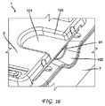
図10は、セットトップボックス1の下部の斜視図を示す。図10は、スマートカード101がセットトップボックス1にどのように挿入されるか又はスマートカード101がセットトップボックス1からどのように取り外されるかを例示する。スマートカード101は、セットトップボックスのある面に位置されるスロット91を通してスマートカードリーダ3に挿入される。このカードのアクセス領域は、スマートカード101をつかむために湾曲した部分の下であって且つスマートカードの上に指が到達するのを可能にするため、セットトップボックスの上に向けて湾曲した凹面の輪郭102を有するトップカバー7を本質的に含む。さらに、底面フレーム2は、スマートカードをつかむためにスマートカード101の下に指が到達するのを可能にするため、内側に延びるセットトップボックスの下にある補足のスロット103を有する。
FIG. 10 shows a perspective view of the lower part of the set top box 1. FIG. 10 illustrates how the
なお、図面はこの開示の概念を例示するためのものであって、必ずしも、この開示を例示する可能性のあるコンフィギュレーションではないことを理解されたい。例えば、セットトップボックス及びスマートカードに関して例示されているが、本発明は、ハードドライブを有する他の電子装置に適用可能であり、これらの他の装置は、スマートカード以外のタイプの情報カードを有することができる。さらに、ヒートシンクは、適所に堅固に備え付けられるか、溶接されるか又ははんだ付けされる。
以上の実施の形態に関し、更に以下の付記を開示する。
(付記1)
底面のフレーム部分と、
前記底面のフレーム部分の上にある情報カードリーダと、
断熱層と、
前記断熱層の上にある回路ボードと、
前記回路ボードの上にある天板のヒートシンクと、
前記天板のヒートシンクの上にあるトップカバーと、
を有する電子装置。
(付記2)
前記断熱層は、開口部を有し、前記開口部を通して前記情報カードリーダは、前記回路ボードに電気的に接続される、
付記1記載の電子装置。
(付記3)
前記天板のヒートシンクは、中央の凹部を囲む平面の周辺部を有し、前記中央の凹部は、前記回路ボード上の熱発生コンポーネントと接触する、
付記1記載の電子装置。
(付記4)
遠隔制御受信機のアセンブリを更に備える、
付記1記載の電子装置。
(付記5)
前記遠隔制御受信機のアセンブリは赤外線受信機である、
付記4記載の電子装置。
(付記6)
前記遠隔制御受信機のアセンブリは、無線周波受信機である、
付記4記載の電子装置。
(付記7)
前記天板のヒートシンクは、前記平面の周辺部から延びる壁部分を有し、前記壁部分は、前記遠隔制御のアセンブリに接触し、前記遠隔制御のアセンブリを固定する、
付記4記載の電子装置。
(付記8)
前記天板のヒートシンクは、第二の中央の凹部を有し、前記第二の中央の凹部は、前記回路ボード上の第二の熱発生コンポーネントと接触する、
付記3記載の電子装置。
(付記9)
前記底面のフレーム部分は、前記底面のフレーム部分の2つの対向する面でクリップを受けるスロットを有する垂直方向に延びる部分のペアを有し、
前記天板のヒートシンクは、対向する壁部分のペアを有し、それぞれの対向する壁部分は、前記クリップを受けるスロットにはめ込む2つのクリップであって、前記天板のヒートシンクを前記底面のフレーム部分に固定する2つのクリップを有する、
付記3記載の電子装置。
(付記10)
前記底部のフレーム部分と前記2つの対向する面のうちの1つとの間のギャップにより形成される情報カードリーダのスロットを更に有する、
付記9記載の電子装置。
(付記11)
前記電子装置は、セットトップボックスである、
付記1記載の電子装置。
(付記12)
前記情報カードリーダは、スマートカードリーダである、
付記1記載の電子装置。
(付記13)
遠隔制御受信機のアセンブリを更に有し、
前記天板のヒートシンクは、中央の凹部を囲む平面の周辺部分を有し、前記平面の凹部は、前記回路ボード上の熱発生コンポーネントと接触し、
前記天板のヒートシンクは、前記平面の周辺部から延びる壁部分を有し、前記壁部分は、前記遠隔制御受信機のアセンブリに接触し、前記遠隔制御受信機のアセンブリを固定する、
付記2記載の電子装置。
(付記14)
前記天板のヒートシンクは、第二の中央の凹部を有し、前記第二の中央の凹部は、前記回路ボード上の第二の熱発生コンポーネントに接触する、
付記13記載の電子装置。
(付記15)
前記底部のフレーム部分は、2つの対向する面にクリップを受けるスロットを有する垂直方向に延びる部分のペアを有し、
前記天板のヒートシンクは、他の対向する壁部分のペアを有し、それぞれ対向する壁部分は、前記クリップを受けるスロットにはめ込む2つのクリップであって、前記底部のフレーム部分において前記天板のヒートシンクを固定する2つのクリップを有する、
付記14記載の電子装置。
It should be understood that the drawings are for purposes of illustrating the concepts of the disclosure and are not necessarily the configurations that may illustrate the disclosure. For example, although illustrated with respect to set-top boxes and smart cards, the present invention is applicable to other electronic devices having hard drives, and these other devices have types of information cards other than smart cards. be able to. In addition, the heat sink is securely mounted in place, welded or soldered.
Regarding the above embodiment, the following additional notes are disclosed.
(Appendix 1)
The bottom frame part,
An information card reader on the bottom frame portion;
An insulation layer;
A circuit board overlying the thermal insulation layer;
A heat sink on the top plate on the circuit board;
A top cover on the heat sink of the top plate;
An electronic device.
(Appendix 2)
The heat insulating layer has an opening, and the information card reader is electrically connected to the circuit board through the opening.
The electronic device according to appendix 1.
(Appendix 3)
The heat sink of the top plate has a planar periphery surrounding a central recess, the central recess contacting a heat generating component on the circuit board;
The electronic device according to appendix 1.
(Appendix 4)
Further comprising a remote control receiver assembly;
The electronic device according to appendix 1.
(Appendix 5)
The remote control receiver assembly is an infrared receiver;
The electronic device according to
(Appendix 6)
The remote control receiver assembly is a radio frequency receiver;
The electronic device according to
(Appendix 7)
The heat sink of the top plate has a wall portion extending from the periphery of the plane, the wall portion contacting the remote control assembly and securing the remote control assembly;
The electronic device according to
(Appendix 8)
The heat sink of the top plate has a second central recess, and the second central recess contacts a second heat generating component on the circuit board;
The electronic device according to attachment 3.
(Appendix 9)
The bottom frame portion has a pair of vertically extending portions having slots for receiving clips on two opposite sides of the bottom frame portion;
The heat sink of the top plate has a pair of opposing wall portions, each opposing wall portion being two clips that fit into a slot that receives the clip, the heat sink of the top plate being a frame portion of the bottom surface Having two clips to fasten to,
The electronic device according to attachment 3.
(Appendix 10)
Further comprising an information card reader slot formed by a gap between the bottom frame portion and one of the two opposing surfaces;
The electronic device according to
(Appendix 11)
The electronic device is a set-top box;
The electronic device according to appendix 1.
(Appendix 12)
The information card reader is a smart card reader.
The electronic device according to appendix 1.
(Appendix 13)
Further comprising a remote control receiver assembly;
The heat sink of the top plate has a planar peripheral portion surrounding a central recess, the planar recess contacting a heat generating component on the circuit board;
The heat sink of the top plate has a wall portion extending from the periphery of the plane, the wall portion contacting the remote control receiver assembly and securing the remote control receiver assembly;
The electronic device according to
(Appendix 14)
The heat sink of the top plate has a second central recess, and the second central recess contacts a second heat generating component on the circuit board;
The electronic device according to appendix 13.
(Appendix 15)
The bottom frame portion has a pair of vertically extending portions having slots for receiving clips on two opposing faces;
The heat sink of the top plate has a pair of other opposing wall portions, each opposing wall portion being two clips that fit into a slot that receives the clip, wherein the top plate has a frame portion at the bottom. Having two clips to secure the heat sink,
The electronic device according to appendix 14.
Claims (12)
前記底面フレーム部分の上にある情報カードリーダと、
断熱層と、
前記断熱層の上にある回路ボードと、
遠隔制御受信機アセンブリと、
前記回路ボードの上にある天板ヒートシンクと、
前記天板ヒートシンクの上にあるトップカバーと、
を有し、前記天板ヒートシンクは、平面状の周辺部から延びる壁部分を有し、前記壁部分は、前記遠隔制御受信機アセンブリに接触することにより前記遠隔制御受信機アセンブリを安定させる、電子装置。 The bottom frame part,
An information card reader on the bottom frame part;
An insulation layer;
A circuit board overlying the thermal insulation layer;
A remote control receiver assembly;
A top plate heat sink on the circuit board;
A top cover on the top heat sink;
Have a, the top plate heat sink has a wall portion extending from the flat peripheral portion, said wall portion stabilizes the remote control receiver assembly by contact with the remote control receiver assembly, electronic apparatus.
請求項1記載の電子装置。 The heat insulating layer has an opening, and the information card reader is electrically connected to the circuit board through the opening.
The electronic device according to claim 1.
請求項1記載の電子装置。 The top plate heat sink has a planar periphery surrounding a central recess, the central recess contacting a heat generating component on the circuit board;
The electronic device according to claim 1.
請求項1記載の電子装置。 The remote control receiver assembly is an infrared receiver or a radio frequency receiver;
The electronic device according to claim 1 .
請求項3記載の電子装置。 The top heat sink has a second central recess, the second central recess contacting a second heat generating component on the circuit board;
The electronic device according to claim 3.
前記天板ヒートシンクは、一対の対向する壁部分を有し、それぞれの対向する壁部分は、前記クリップ受入れスロットにはめ込む2つのクリップであって、前記天板ヒートシンクを前記底面フレーム部分に固定する2つのクリップを有する、
請求項3記載の電子装置。 The bottom frame portion has a pair of vertically extending portions having clip receiving slots at two opposing ends of the bottom frame portion;
The top plate heat sink has a pair of opposing wall portions, each of the opposing wall portions being two clips that fit into the clip receiving slot, and fixing the top plate heat sink to the bottom frame portion 2 Having two clips,
The electronic device according to claim 3.
請求項6記載の電子装置。 An information card reader slot formed by a gap between the bottom frame portion and one of the two opposing side surfaces of the top heat sink ;
The electronic device according to claim 6 .
請求項1記載の電子装置。 The electronic device is a set-top box;
The electronic device according to claim 1.
請求項1記載の電子装置。 The information card reader is a smart card reader.
The electronic device according to claim 1.
請求項2記載の電子装置。 Before Kitenban heat sink has a planar peripheral portion surrounding the central recess, the central recess is in contact with the heat generating component on the circuit board,
The electronic device according to claim 2.
請求項10記載の電子装置。 The top heat sink has a second central recess, the second central recess contacting a second heat generating component on the circuit board;
The electronic device according to claim 10 .
前記天板ヒートシンクは、他の一対の対向する壁部分を有し、それぞれの対向する壁部分は、前記クリップ受入れスロットにはめ込む2つのクリップであって、前記底面フレーム部分に前記天板ヒートシンクを固定する2つのクリップを有する、
請求項11記載の電子装置。 The bottom frame portion has a pair of vertically extending portions with clip receiving slots at two opposite ends ,
The top plate heat sink has another pair of opposing wall portions, each of the opposing wall portions being two clips that fit into the clip receiving slot, and fixing the top plate heat sink to the bottom frame portion Have two clips to
The electronic device according to claim 11 .
Applications Claiming Priority (5)
| Application Number | Priority Date | Filing Date | Title |
|---|---|---|---|
| US201161464829P | 2011-03-09 | 2011-03-09 | |
| US61/464,829 | 2011-03-09 | ||
| US201161464965P | 2011-03-11 | 2011-03-11 | |
| US61/464,965 | 2011-03-11 | ||
| PCT/US2012/028000 WO2012122230A2 (en) | 2011-03-09 | 2012-03-07 | Set top box or server having snap-in heat sink and smart card reader |
Publications (3)
| Publication Number | Publication Date |
|---|---|
| JP2014514732A JP2014514732A (en) | 2014-06-19 |
| JP2014514732A5 JP2014514732A5 (en) | 2015-04-23 |
| JP5981463B2 true JP5981463B2 (en) | 2016-08-31 |
Family
ID=46798761
Family Applications (1)
| Application Number | Title | Priority Date | Filing Date |
|---|---|---|---|
| JP2013557818A Active JP5981463B2 (en) | 2011-03-09 | 2012-03-07 | Electronic equipment |
Country Status (7)
| Country | Link |
|---|---|
| US (1) | US9392317B2 (en) |
| EP (1) | EP2684375B8 (en) |
| JP (1) | JP5981463B2 (en) |
| KR (1) | KR20140061299A (en) |
| CN (1) | CN103858067A (en) |
| BR (1) | BR112013022150B1 (en) |
| WO (1) | WO2012122230A2 (en) |
Families Citing this family (30)
| Publication number | Priority date | Publication date | Assignee | Title |
|---|---|---|---|---|
| BR112012014093B1 (en) * | 2009-12-09 | 2020-09-29 | Interdigital Ce Patent Holdings | ELECTRONIC DEVICE HAVING MICRO PERFORATIONS |
| EP2540148B1 (en) | 2010-02-25 | 2016-09-28 | Thomson Licensing | Miniature multilayer radiative cooling case with hidden quick release snaps |
| KR20130077841A (en) | 2010-05-19 | 2013-07-09 | 톰슨 라이센싱 | Set-top box having dissipating thermal loads |
| CN104011818A (en) * | 2011-03-09 | 2014-08-27 | 汤姆逊许可公司 | Set top box with reset button and light guide |
| EP2684375B8 (en) | 2011-03-09 | 2017-12-13 | Thomson Licensing | Set top box or server having snap-in heat sink and smart card reader |
| BR112014000762A2 (en) | 2011-07-14 | 2017-02-14 | Thomson Licensing | bos top set converter having snap-in heat sink and smart card reader with a containment to retain the heat sink |
| KR20140041748A (en) * | 2011-07-18 | 2014-04-04 | 톰슨 라이센싱 | Design for retention base to fixture on cover removal fixture |
| BR112014010607A2 (en) * | 2011-11-21 | 2017-04-25 | Thomson Licensing | cooler to retain a heat sink |
| JP5811278B2 (en) * | 2012-05-22 | 2015-11-11 | 株式会社村田製作所 | Compound module |
| CN104871113A (en) | 2012-10-11 | 2015-08-26 | 汤姆逊许可公司 | Docking mechanism for locking and undocking multiple electronic instruments |
| TW201444460A (en) * | 2013-05-14 | 2014-11-16 | Hon Hai Prec Ind Co Ltd | Heat sink assembly |
| US9736964B2 (en) | 2013-06-27 | 2017-08-15 | Thomson Licensing | Device cover for thermal management |
| BR112016010709B1 (en) | 2013-11-13 | 2022-05-03 | Interdigital Madison Patent Holdings, Sas | Electronic device and method for mounting an electronic device that has at least one antenna |
| JP6182440B2 (en) * | 2013-12-02 | 2017-08-16 | 新電元工業株式会社 | Fixed structure |
| KR20160049646A (en) * | 2014-10-28 | 2016-05-10 | 삼성전자주식회사 | Set top box anddisplay apparatus having discrete type card part, and card part-mounting methods thereof |
| DE102015226712B4 (en) * | 2014-12-26 | 2024-10-24 | Omron Corporation | PRINTED CIRCUIT BOARD AND ELECTRONIC COMPONENT |
| US9390299B1 (en) | 2015-02-25 | 2016-07-12 | Echostar Technologies L.L.C. | High data transfer smart card reader with heat sink |
| JP6333215B2 (en) * | 2015-05-19 | 2018-05-30 | オムロンオートモーティブエレクトロニクス株式会社 | Printed circuit boards, electronic devices |
| US9760742B2 (en) | 2015-06-26 | 2017-09-12 | Echostar Technologies L.L.C. | Dual purpose press-bar and heat sink for high data transfer integrated circuit card reader |
| JP6274196B2 (en) * | 2015-12-16 | 2018-02-07 | 株式会社オートネットワーク技術研究所 | Electrical junction box |
| CN108702852B (en) * | 2016-03-14 | 2021-03-16 | 索尤若驱动有限及两合公司 | Electrical device having a housing part and a cover part |
| DK3449706T3 (en) | 2016-04-28 | 2021-05-10 | Teleste Oyj | STRUCTURAL DECORATION FOR A CATV FIELD DECORATION |
| DE102017212968B4 (en) * | 2016-08-05 | 2024-02-01 | Robert Bosch Gmbh | HOUSING STRUCTURE FOR AN ELECTRONIC CONTROL UNIT AND PRODUCTION METHOD |
| US10043043B1 (en) | 2017-02-07 | 2018-08-07 | DISH Technologies L.L.C. | Integrated circuit card reader with improved heat dissipation |
| CN111034380A (en) * | 2017-08-08 | 2020-04-17 | Nec平台株式会社 | Heat radiation structure |
| WO2019106957A1 (en) * | 2017-11-28 | 2019-06-06 | ソニーセミコンダクタソリューションズ株式会社 | Tuner module and receiving device |
| EP3684154B1 (en) * | 2019-01-21 | 2024-03-06 | Aptiv Technologies Limited | Thermally conductive insert element for electronic unit |
| JP7203784B2 (en) | 2020-03-27 | 2023-01-13 | 株式会社ソニー・インタラクティブエンタテインメント | Electronic equipment and its outer panel |
| EP3955285A1 (en) * | 2020-08-14 | 2022-02-16 | Siemens Aktiengesellschaft | Power module and device for cooling a power module |
| WO2022132244A1 (en) * | 2020-12-15 | 2022-06-23 | Arris Enterprises Llc | Multisided heat spreader |
Family Cites Families (94)
| Publication number | Priority date | Publication date | Assignee | Title |
|---|---|---|---|---|
| US4887147A (en) | 1987-07-01 | 1989-12-12 | Digital Equipment Corporation | Thermal package for electronic components |
| JPH02307182A (en) * | 1989-05-23 | 1990-12-20 | Hitachi Maxell Ltd | Ic card reader/writer |
| JP2758283B2 (en) | 1991-06-17 | 1998-05-28 | 株式会社東芝 | Hard disk pack detachable mechanism |
| US6850252B1 (en) * | 1999-10-05 | 2005-02-01 | Steven M. Hoffberg | Intelligent electronic appliance system and method |
| JPH06227553A (en) | 1993-01-28 | 1994-08-16 | Yazaki Corp | Locking structure |
| US5620242A (en) | 1993-04-19 | 1997-04-15 | Motorola, Inc. | Portable radio battery latch |
| JP3251734B2 (en) | 1993-08-18 | 2002-01-28 | 株式会社日立テレコムテクノロジー | Electronic device housing structure |
| JPH0786471A (en) | 1993-09-20 | 1995-03-31 | Hitachi Ltd | Semiconductor module |
| US5667397A (en) * | 1994-12-01 | 1997-09-16 | The Whitaker Corporation | Smart card connector |
| US5917236A (en) | 1995-12-08 | 1999-06-29 | Hewlett-Packard Company | Packaging system for field effects transistors |
| US5691878A (en) | 1996-02-02 | 1997-11-25 | Motorola, Inc. | Snap-lockable housing for fluorescent lamp ballasts |
| JP3776169B2 (en) | 1996-06-13 | 2006-05-17 | 任天堂株式会社 | Heat dissipation structure of electronic equipment |
| JPH1065385A (en) * | 1996-08-21 | 1998-03-06 | Mitsubishi Electric Corp | Substrate case structure |
| JPH10154390A (en) | 1996-11-20 | 1998-06-09 | Nippon Columbia Co Ltd | Disk reproducing device |
| US6049469A (en) | 1997-08-20 | 2000-04-11 | Dell Usa, L.P. | Combination electromagnetic shield and heat spreader |
| US7082033B1 (en) | 1998-02-13 | 2006-07-25 | Micron Technology, Inc. | Removing heat from integrated circuit devices mounted on a support structure |
| JP3597368B2 (en) | 1998-02-16 | 2004-12-08 | アルプス電気株式会社 | Electronics |
| US6021044A (en) | 1998-08-13 | 2000-02-01 | Data General Corporation | Heatsink assembly |
| JP2000269671A (en) | 1999-03-19 | 2000-09-29 | Toshiba Corp | Electronic apparatus |
| JP2000269675A (en) | 1999-03-19 | 2000-09-29 | Sony Corp | Cooling device and set top box |
| US6411522B1 (en) | 1999-04-01 | 2002-06-25 | Western Digital Ventures, Inc. | Integrated computer module with EMI shielding plate |
| JP3982941B2 (en) | 1999-04-12 | 2007-09-26 | 富士通株式会社 | Storage device |
| US6382995B1 (en) * | 1999-05-20 | 2002-05-07 | Itt Manufacturing Enterprises, Inc | Smart card connector with retain and eject means |
| EP1059600B1 (en) * | 1999-06-08 | 2007-09-12 | Molex Incorporated | Portable smart card reader assembly |
| CN1532765A (en) * | 1999-07-02 | 2004-09-29 | 3M创新有限公司 | Intelligent card reader |
| JP2001147061A (en) | 1999-09-08 | 2001-05-29 | Sega Corp | Electronic equipment having cooling device |
| GB2355017B (en) | 1999-09-23 | 2001-09-12 | Lorenzo Battisti | Porous element |
| US6212074B1 (en) * | 2000-01-31 | 2001-04-03 | Sun Microsystems, Inc. | Apparatus for dissipating heat from a circuit board having a multilevel surface |
| US6317325B1 (en) | 2000-02-23 | 2001-11-13 | Lucent Technologies Inc. | Apparatus for protecting circuit pack assemblies from thermal and electromagnetic effects |
| JP3923703B2 (en) | 2000-03-29 | 2007-06-06 | ローム株式会社 | Printed wiring board having heat dissipation means |
| JP2001358482A (en) | 2000-04-14 | 2001-12-26 | Matsushita Refrig Co Ltd | Heat radiative module |
| FR2809871B1 (en) * | 2000-06-05 | 2002-07-19 | Itt Mfg Entpr S Inc | ELECTRICAL CONNECTOR WITH IMPROVED CONTACT BLADES FOR CONNECTION OF AN INTEGRATED CIRCUIT (S) CARD |
| US20020051338A1 (en) | 2000-07-27 | 2002-05-02 | Lixin Jiang | Acoustic enclosure for an air cooled hard disk drive |
| DE10051159C2 (en) * | 2000-10-16 | 2002-09-19 | Osram Opto Semiconductors Gmbh | LED module, e.g. White light source |
| JP2002134970A (en) | 2000-10-26 | 2002-05-10 | Denso Corp | Electronic controller |
| US6524361B1 (en) | 2000-10-26 | 2003-02-25 | Hubbell Incorporated | Micro-porous filter |
| EP1248507A1 (en) | 2001-04-04 | 2002-10-09 | Siemens Aktiengesellschaft | High frequencies module for audio device with improved heat dissipation |
| JP2002324989A (en) | 2001-04-26 | 2002-11-08 | Murata Mach Ltd | Heat radiating structure for printed circuit board |
| JP4057796B2 (en) | 2001-07-03 | 2008-03-05 | 株式会社東芝 | Non-aqueous electrolyte air battery |
| US6881077B2 (en) | 2002-07-22 | 2005-04-19 | Siemens Vdo Automotive Corporation | Automotive control module housing |
| US6735085B2 (en) | 2002-08-15 | 2004-05-11 | Hon Hai Precision Ind. Co., Ltd. | Foldable retention device for land grid array connector assembly |
| JP2004186294A (en) | 2002-12-02 | 2004-07-02 | Denso Corp | Electronic apparatus |
| JP4039316B2 (en) | 2003-06-09 | 2008-01-30 | 株式会社明電舎 | Electronic equipment cooling structure |
| JP2005005424A (en) | 2003-06-11 | 2005-01-06 | Matsushita Electric Ind Co Ltd | Electromagnetic-wave shielding panel and hot-insulating/cold-insulating equipment using it, electronic equipment, clothing item and housing member |
| DE60319523T2 (en) | 2003-08-07 | 2009-03-26 | Harman Becker Automotive Systems Gmbh | Device for cooling semiconductor components on printed circuit boards |
| EP1511314B1 (en) | 2003-08-29 | 2009-01-07 | Thomson Licensing | System and method for smart card reader activation |
| EP1511313A1 (en) * | 2003-08-29 | 2005-03-02 | Thomson Licensing S.A. | Control device, smart card reading activation device and associated products |
| US7203065B1 (en) * | 2003-11-24 | 2007-04-10 | Ciena Corporation | Heatsink assembly |
| US20050128710A1 (en) | 2003-12-15 | 2005-06-16 | Beiteimal Abdlmonem H. | Cooling system for electronic components |
| TWI256192B (en) | 2004-04-15 | 2006-06-01 | Acbel Polytech Inc | Power adapter with heat sink device |
| FR2871022B1 (en) * | 2004-05-25 | 2006-11-03 | Valeo Electronique Sys Liaison | HOUSING FOR ELECTRIC OR ELECTRONIC CIRCUITS |
| GB0413340D0 (en) * | 2004-06-15 | 2004-07-21 | Pace Micro Tech Plc | Improvements to electrical apparatus |
| FR2875917B3 (en) | 2004-09-29 | 2007-01-05 | Alvaro Lemos | FOLDING VENTILATION DEVICE FOR THE PROTECTION OF PORTABLE MICROCOMPUTERS |
| US7215551B2 (en) | 2004-09-29 | 2007-05-08 | Super Talent Electronics, Inc. | Memory module assembly including heat sink attached to integrated circuits by adhesive |
| TWI247574B (en) | 2004-11-30 | 2006-01-11 | Silicon Integrated Sys Corp | Heat dissipation mechanism for electronic device |
| US7791874B2 (en) | 2004-12-30 | 2010-09-07 | Microsoft Corporation | Removable module for a console |
| JP2006229046A (en) | 2005-02-18 | 2006-08-31 | Toshiba Corp | Heat radiator and heat radiating method for electronic apparatus |
| JP4445409B2 (en) | 2005-02-23 | 2010-04-07 | 株式会社東芝 | Heat dissipation device for electronic equipment |
| US7158380B2 (en) * | 2005-03-25 | 2007-01-02 | Scientific-Atlanta, Inc. | Heatsink for digital video recorder |
| US7350705B1 (en) * | 2005-03-28 | 2008-04-01 | International Technologies & Systems Corp. | Compact robust smart card reader |
| US7519627B2 (en) * | 2005-08-04 | 2009-04-14 | International Business Machines Corporation | Method for automatic deletion scheduling of the plurality of files in multi-user a digital playback system |
| US7362578B2 (en) | 2005-08-16 | 2008-04-22 | Tyco Electronics Corporation | Heat sink fastening system |
| DE202005013758U1 (en) | 2005-08-31 | 2006-01-19 | Sampo Corp., Kuei Shan Hsiang | Cooling mechanism for a portable digital TV includes a front and rear casing with a partition for separating off retaining areas in the front casing |
| US7272001B2 (en) | 2005-09-09 | 2007-09-18 | King Young Technology Co., Ltd. | External conductive heat dissipating device for microcomputers |
| WO2007089321A2 (en) | 2005-11-23 | 2007-08-09 | Comcast Cable Holdings, Llc | Settop box (stb) |
| US20070177356A1 (en) | 2006-02-01 | 2007-08-02 | Jeffrey Panek | Three-dimensional cold plate and method of manufacturing same |
| JP4742893B2 (en) | 2006-02-03 | 2011-08-10 | 日本電気株式会社 | Heating device mounting apparatus and heat dissipation device |
| US7450387B2 (en) | 2006-03-02 | 2008-11-11 | Tdk Innoveta Technologies, Inc. | System for cooling electronic components |
| GB2436170A (en) | 2006-03-17 | 2007-09-19 | Amstrad Plc | Cooling or heating device in a chip card reader |
| US7664198B2 (en) | 2006-03-21 | 2010-02-16 | Kyocera Corporation | System and method for broadcasting data over a wireless network using rateless codes |
| JP2008034474A (en) | 2006-07-26 | 2008-02-14 | Sharp Corp | Heat transfer sheet and substrate device |
| JP5179746B2 (en) | 2006-11-22 | 2013-04-10 | 京セラ株式会社 | Mobile terminal device |
| US7518875B2 (en) | 2006-12-14 | 2009-04-14 | International Business Machines Corporation | Securing heat sinks to a device under test |
| EP2145284B1 (en) | 2007-05-04 | 2013-04-17 | Thomson Licensing | Smart card heat sink |
| DE202007006626U1 (en) * | 2007-05-09 | 2007-10-04 | Hamburg Industries Co., Ltd., Shen Keng | connecting device |
| JP5009679B2 (en) | 2007-05-15 | 2012-08-22 | 株式会社リコー | Information processing device |
| US8023260B2 (en) * | 2007-09-04 | 2011-09-20 | Apple Inc. | Assembly of an electronic device |
| WO2009057124A2 (en) | 2007-11-01 | 2009-05-07 | Innomedia Technologies Pvt. Ltd. | A set-top-box cabinet for natural cooling of internal electronics |
| JP4857252B2 (en) | 2007-12-07 | 2012-01-18 | 株式会社日立製作所 | Electronics |
| TW200943036A (en) * | 2008-04-11 | 2009-10-16 | Foxconn Tech Co Ltd | Heat dissipation device |
| CN101685330A (en) * | 2008-09-24 | 2010-03-31 | 富准精密工业(深圳)有限公司 | Radiating device and notebook computer having same |
| JP4473923B2 (en) * | 2008-10-22 | 2010-06-02 | 株式会社東芝 | Electronics |
| FR2944408B1 (en) | 2009-04-14 | 2012-09-21 | Eads Europ Aeronautic Defence | BOX FOR ELECTRONIC BOARD EMBARCATED |
| KR101552357B1 (en) * | 2009-05-29 | 2015-09-11 | 엘지이노텍 주식회사 | tuner module |
| BR112012014093B1 (en) | 2009-12-09 | 2020-09-29 | Interdigital Ce Patent Holdings | ELECTRONIC DEVICE HAVING MICRO PERFORATIONS |
| JP2011176096A (en) | 2010-02-24 | 2011-09-08 | Mitsumi Electric Co Ltd | Electronic apparatus |
| EP2540148B1 (en) | 2010-02-25 | 2016-09-28 | Thomson Licensing | Miniature multilayer radiative cooling case with hidden quick release snaps |
| US8620162B2 (en) * | 2010-03-25 | 2013-12-31 | Apple Inc. | Handheld electronic device with integrated transmitters |
| KR20130077841A (en) | 2010-05-19 | 2013-07-09 | 톰슨 라이센싱 | Set-top box having dissipating thermal loads |
| USD631449S1 (en) | 2010-08-02 | 2011-01-25 | Thomson Licensing | Set top box |
| GB201016047D0 (en) * | 2010-09-24 | 2010-11-10 | Pace Plc | Means for heating dissipation for electrical and/or electronic apparatus |
| EP2684375B8 (en) | 2011-03-09 | 2017-12-13 | Thomson Licensing | Set top box or server having snap-in heat sink and smart card reader |
| US8619427B2 (en) * | 2011-03-21 | 2013-12-31 | Eldon Technology Limited | Media content device chassis with internal extension members |
| US9007773B2 (en) | 2012-08-31 | 2015-04-14 | Flextronics Ap, Llc | Housing unit with heat sink |
-
2012
- 2012-03-07 EP EP12755003.6A patent/EP2684375B8/en active Active
- 2012-03-07 JP JP2013557818A patent/JP5981463B2/en active Active
- 2012-03-07 BR BR112013022150-0A patent/BR112013022150B1/en active IP Right Grant
- 2012-03-07 US US14/002,749 patent/US9392317B2/en active Active
- 2012-03-07 CN CN201280012322.7A patent/CN103858067A/en active Pending
- 2012-03-07 WO PCT/US2012/028000 patent/WO2012122230A2/en active Application Filing
- 2012-03-07 KR KR1020137023482A patent/KR20140061299A/en active Search and Examination
Also Published As
| Publication number | Publication date |
|---|---|
| BR112013022150B1 (en) | 2022-06-21 |
| EP2684375B1 (en) | 2017-11-01 |
| EP2684375B8 (en) | 2017-12-13 |
| US20130347051A1 (en) | 2013-12-26 |
| CN103858067A (en) | 2014-06-11 |
| EP2684375A2 (en) | 2014-01-15 |
| EP2684375A4 (en) | 2015-08-05 |
| WO2012122230A2 (en) | 2012-09-13 |
| US9392317B2 (en) | 2016-07-12 |
| BR112013022150A2 (en) | 2016-12-06 |
| WO2012122230A3 (en) | 2014-04-17 |
| JP2014514732A (en) | 2014-06-19 |
| KR20140061299A (en) | 2014-05-21 |
Similar Documents
| Publication | Publication Date | Title |
|---|---|---|
| JP5981463B2 (en) | Electronic equipment | |
| JP2014514732A5 (en) | ||
| EP2783557B1 (en) | Hold down for retaining a heat sink | |
| JP5792386B2 (en) | Set-top box with snap-in heat sink and smart card reader with heat sink retention fastener | |
| JP6085684B2 (en) | Set top box with heat sink pressurizing means | |
| US9122899B2 (en) | Card connector with improved heat-dissipation, retention, and ESD protection features | |
| EP1891847B1 (en) | Electronic appliance provided with a cooling assembly for cooling a consumer insertable module, and cooling assembly for cooling such module | |
| US8544745B2 (en) | Heat-dissipating card connector | |
| KR20120129885A (en) | Set-top box having microperforations | |
| KR20080029510A (en) | User authentication card access device for broadcasting receiver and broadcasting receiver equipped with same | |
| CN103138092A (en) | Mounting socket for mobile phone | |
| KR20160086334A (en) | Heatsink alignment to printed circuit board | |
| JP2013222631A (en) | Connector for card | |
| TW202130062A (en) | Connector | |
| JP2017501605A (en) | Compact wireless antenna implementation for electrostatic discharge protection | |
| JP2013222629A (en) | Connector for card | |
| CN109196744B (en) | base unit | |
| WO2013111190A1 (en) | Display system, attachment and display unit | |
| KR20190066442A (en) | Card Connector |
Legal Events
| Date | Code | Title | Description |
|---|---|---|---|
| A521 | Request for written amendment filed |
Free format text: JAPANESE INTERMEDIATE CODE: A523 Effective date: 20150306 |
|
| A621 | Written request for application examination |
Free format text: JAPANESE INTERMEDIATE CODE: A621 Effective date: 20150306 |
|
| A977 | Report on retrieval |
Free format text: JAPANESE INTERMEDIATE CODE: A971007 Effective date: 20151029 |
|
| A131 | Notification of reasons for refusal |
Free format text: JAPANESE INTERMEDIATE CODE: A131 Effective date: 20151104 |
|
| A521 | Request for written amendment filed |
Free format text: JAPANESE INTERMEDIATE CODE: A523 Effective date: 20160201 |
|
| TRDD | Decision of grant or rejection written | ||
| A01 | Written decision to grant a patent or to grant a registration (utility model) |
Free format text: JAPANESE INTERMEDIATE CODE: A01 Effective date: 20160705 |
|
| A61 | First payment of annual fees (during grant procedure) |
Free format text: JAPANESE INTERMEDIATE CODE: A61 Effective date: 20160728 |
|
| R150 | Certificate of patent or registration of utility model |
Ref document number: 5981463 Country of ref document: JP Free format text: JAPANESE INTERMEDIATE CODE: R150 |
|
| R250 | Receipt of annual fees |
Free format text: JAPANESE INTERMEDIATE CODE: R250 |
|
| S111 | Request for change of ownership or part of ownership |
Free format text: JAPANESE INTERMEDIATE CODE: R313113 |
|
| S531 | Written request for registration of change of domicile |
Free format text: JAPANESE INTERMEDIATE CODE: R313531 |
|
| R350 | Written notification of registration of transfer |
Free format text: JAPANESE INTERMEDIATE CODE: R350 |
|
| R250 | Receipt of annual fees |
Free format text: JAPANESE INTERMEDIATE CODE: R250 |
|
| R250 | Receipt of annual fees |
Free format text: JAPANESE INTERMEDIATE CODE: R250 |
|
| R250 | Receipt of annual fees |
Free format text: JAPANESE INTERMEDIATE CODE: R250 |
|
| R250 | Receipt of annual fees |
Free format text: JAPANESE INTERMEDIATE CODE: R250 |
|
| R250 | Receipt of annual fees |
Free format text: JAPANESE INTERMEDIATE CODE: R250 |