JP5979291B1 - Optical device - Google Patents
Optical device Download PDFInfo
- Publication number
- JP5979291B1 JP5979291B1 JP2015150035A JP2015150035A JP5979291B1 JP 5979291 B1 JP5979291 B1 JP 5979291B1 JP 2015150035 A JP2015150035 A JP 2015150035A JP 2015150035 A JP2015150035 A JP 2015150035A JP 5979291 B1 JP5979291 B1 JP 5979291B1
- Authority
- JP
- Japan
- Prior art keywords
- light
- deflection
- optical
- image
- guide plate
- Prior art date
- Legal status (The legal status is an assumption and is not a legal conclusion. Google has not performed a legal analysis and makes no representation as to the accuracy of the status listed.)
- Active
Links
- 230000003287 optical effect Effects 0.000 title claims abstract description 244
- 238000009826 distribution Methods 0.000 claims abstract description 23
- 230000007480 spreading Effects 0.000 claims abstract description 9
- 238000003892 spreading Methods 0.000 claims abstract description 9
- 239000000463 material Substances 0.000 claims description 8
- 230000001902 propagating effect Effects 0.000 claims description 6
- 230000004048 modification Effects 0.000 description 39
- 238000012986 modification Methods 0.000 description 39
- 238000000034 method Methods 0.000 description 9
- 230000004907 flux Effects 0.000 description 7
- 238000007665 sagging Methods 0.000 description 7
- 239000003973 paint Substances 0.000 description 5
- 239000003086 colorant Substances 0.000 description 4
- 239000011159 matrix material Substances 0.000 description 3
- 230000008569 process Effects 0.000 description 3
- BQCADISMDOOEFD-UHFFFAOYSA-N Silver Chemical compound [Ag] BQCADISMDOOEFD-UHFFFAOYSA-N 0.000 description 2
- 238000010586 diagram Methods 0.000 description 2
- 238000004519 manufacturing process Methods 0.000 description 2
- 238000007747 plating Methods 0.000 description 2
- 229920003229 poly(methyl methacrylate) Polymers 0.000 description 2
- 229920005668 polycarbonate resin Polymers 0.000 description 2
- 239000004431 polycarbonate resin Substances 0.000 description 2
- 239000004926 polymethyl methacrylate Substances 0.000 description 2
- 239000011347 resin Substances 0.000 description 2
- 229920005989 resin Polymers 0.000 description 2
- 229910052709 silver Inorganic materials 0.000 description 2
- 239000004332 silver Substances 0.000 description 2
- 238000007740 vapor deposition Methods 0.000 description 2
- 241001270131 Agaricus moelleri Species 0.000 description 1
- VYZAMTAEIAYCRO-UHFFFAOYSA-N Chromium Chemical compound [Cr] VYZAMTAEIAYCRO-UHFFFAOYSA-N 0.000 description 1
- XAGFODPZIPBFFR-UHFFFAOYSA-N aluminium Chemical compound [Al] XAGFODPZIPBFFR-UHFFFAOYSA-N 0.000 description 1
- 229910052782 aluminium Inorganic materials 0.000 description 1
- 230000004888 barrier function Effects 0.000 description 1
- 229910052804 chromium Inorganic materials 0.000 description 1
- 239000011651 chromium Substances 0.000 description 1
- 239000011521 glass Substances 0.000 description 1
- 238000003384 imaging method Methods 0.000 description 1
- 239000004973 liquid crystal related substance Substances 0.000 description 1
- 239000007787 solid Substances 0.000 description 1
Images


Classifications
-
- G—PHYSICS
- G02—OPTICS
- G02B—OPTICAL ELEMENTS, SYSTEMS OR APPARATUS
- G02B6/00—Light guides; Structural details of arrangements comprising light guides and other optical elements, e.g. couplings
- G02B6/0001—Light guides; Structural details of arrangements comprising light guides and other optical elements, e.g. couplings specially adapted for lighting devices or systems
- G02B6/0011—Light guides; Structural details of arrangements comprising light guides and other optical elements, e.g. couplings specially adapted for lighting devices or systems the light guides being planar or of plate-like form
- G02B6/0033—Means for improving the coupling-out of light from the light guide
- G02B6/0035—Means for improving the coupling-out of light from the light guide provided on the surface of the light guide or in the bulk of it
- G02B6/0036—2-D arrangement of prisms, protrusions, indentations or roughened surfaces
-
- G—PHYSICS
- G02—OPTICS
- G02B—OPTICAL ELEMENTS, SYSTEMS OR APPARATUS
- G02B3/00—Simple or compound lenses
- G02B3/02—Simple or compound lenses with non-spherical faces
- G02B3/08—Simple or compound lenses with non-spherical faces with discontinuous faces, e.g. Fresnel lens
-
- G—PHYSICS
- G02—OPTICS
- G02B—OPTICAL ELEMENTS, SYSTEMS OR APPARATUS
- G02B30/00—Optical systems or apparatus for producing three-dimensional [3D] effects, e.g. stereoscopic images
- G02B30/20—Optical systems or apparatus for producing three-dimensional [3D] effects, e.g. stereoscopic images by providing first and second parallax images to an observer's left and right eyes
- G02B30/26—Optical systems or apparatus for producing three-dimensional [3D] effects, e.g. stereoscopic images by providing first and second parallax images to an observer's left and right eyes of the autostereoscopic type
-
- G—PHYSICS
- G02—OPTICS
- G02B—OPTICAL ELEMENTS, SYSTEMS OR APPARATUS
- G02B30/00—Optical systems or apparatus for producing three-dimensional [3D] effects, e.g. stereoscopic images
- G02B30/50—Optical systems or apparatus for producing three-dimensional [3D] effects, e.g. stereoscopic images the image being built up from image elements distributed over a 3D volume, e.g. voxels
- G02B30/56—Optical systems or apparatus for producing three-dimensional [3D] effects, e.g. stereoscopic images the image being built up from image elements distributed over a 3D volume, e.g. voxels by projecting aerial or floating images
-
- G—PHYSICS
- G02—OPTICS
- G02B—OPTICAL ELEMENTS, SYSTEMS OR APPARATUS
- G02B5/00—Optical elements other than lenses
- G02B5/04—Prisms
- G02B5/045—Prism arrays
-
- G—PHYSICS
- G02—OPTICS
- G02B—OPTICAL ELEMENTS, SYSTEMS OR APPARATUS
- G02B5/00—Optical elements other than lenses
- G02B5/18—Diffraction gratings
- G02B5/1814—Diffraction gratings structurally combined with one or more further optical elements, e.g. lenses, mirrors, prisms or other diffraction gratings
- G02B5/1819—Plural gratings positioned on the same surface, e.g. array of gratings
-
- G—PHYSICS
- G02—OPTICS
- G02B—OPTICAL ELEMENTS, SYSTEMS OR APPARATUS
- G02B6/00—Light guides; Structural details of arrangements comprising light guides and other optical elements, e.g. couplings
- G02B6/0001—Light guides; Structural details of arrangements comprising light guides and other optical elements, e.g. couplings specially adapted for lighting devices or systems
- G02B6/0011—Light guides; Structural details of arrangements comprising light guides and other optical elements, e.g. couplings specially adapted for lighting devices or systems the light guides being planar or of plate-like form
- G02B6/0013—Means for improving the coupling-in of light from the light source into the light guide
- G02B6/0023—Means for improving the coupling-in of light from the light source into the light guide provided by one optical element, or plurality thereof, placed between the light guide and the light source, or around the light source
- G02B6/003—Lens or lenticular sheet or layer
-
- G—PHYSICS
- G02—OPTICS
- G02B—OPTICAL ELEMENTS, SYSTEMS OR APPARATUS
- G02B6/00—Light guides; Structural details of arrangements comprising light guides and other optical elements, e.g. couplings
- G02B6/0001—Light guides; Structural details of arrangements comprising light guides and other optical elements, e.g. couplings specially adapted for lighting devices or systems
- G02B6/0011—Light guides; Structural details of arrangements comprising light guides and other optical elements, e.g. couplings specially adapted for lighting devices or systems the light guides being planar or of plate-like form
- G02B6/0033—Means for improving the coupling-out of light from the light guide
- G02B6/0058—Means for improving the coupling-out of light from the light guide varying in density, size, shape or depth along the light guide
- G02B6/006—Means for improving the coupling-out of light from the light guide varying in density, size, shape or depth along the light guide to produce indicia, symbols, texts or the like
Landscapes
- Physics & Mathematics (AREA)
- General Physics & Mathematics (AREA)
- Optics & Photonics (AREA)
- Optical Integrated Circuits (AREA)
- Diffracting Gratings Or Hologram Optical Elements (AREA)
- Light Guides In General And Applications Therefor (AREA)
- Optical Elements Other Than Lenses (AREA)
- Stereoscopic And Panoramic Photography (AREA)
Abstract
【課題】光源と導光板の端面との間の位置合わせが容易でないこと。【解決手段】光デバイスは、光源からの光を、出射面に平行な面内で伝播する導光板と、出射面に平行な面内に2次元的に配置され、それぞれ導光板内を伝播する光を偏向して、空間上の像を形成する光を出射面から出射させる複数の光偏向部とを備え、複数の光偏向部のそれぞれが、複数の光偏向部のそれぞれに入射した光を、出射面に平行な面内で導光板の導光方向に直交する方向に像に応じた強度分布を持つ光に広げて出射面から出射させることによって、導光方向に直交する方向に沿って配置された複数の光偏向部からの光の集まりによって、像から発散する方向の光が形成される。【選択図】図1Positioning between a light source and an end face of a light guide plate is not easy. An optical device is disposed two-dimensionally in a light guide plate that propagates light from a light source in a plane parallel to an emission surface and in a plane parallel to the emission surface, and propagates through the light guide plate, respectively. A plurality of light deflectors that deflect light to form light in an image from the exit surface, and each of the plurality of light deflectors receives light incident on each of the plurality of light deflectors. Along the direction orthogonal to the light guide direction by spreading the light having an intensity distribution according to the image in the direction orthogonal to the light guide direction of the light guide plate within the plane parallel to the output surface and emitting it from the output surface Light in a direction diverging from the image is formed by a collection of light from the plurality of arranged light deflecting units. [Selection] Figure 1
Description
本発明は、光デバイスに関する。 The present invention relates to an optical device.
導光板と、導光板の端面に設けられた光源と、導光板の表面側に配置した、パララックスバリア方式又はレンズアレイ方式におけるマスク又はレンズアレイとを備えた、立体視可能な表示装置が知られている(例えば、特許文献1参照。)。また、二次元画像を表示する画像表示面を備えた表示部と、画像表示面に離間して配置されたマイクロレンズアレイとから構成され、画像表示面から出射される光をマイクロレンズアレイの表示部とは反対側に位置する空間中の結像面に結像して、立体的二次元画像を表示する立体的二次元画像表示装置が知られている(例えば、特許文献2参照。)。
特許文献1 特開2012−008464号公報
特許文献2 特開2001−255493号公報
A stereoscopic display device comprising a light guide plate, a light source provided on an end surface of the light guide plate, and a parallax barrier type or lens array type mask or lens array disposed on the surface side of the light guide plate is known. (For example, refer to Patent Document 1). In addition, the display unit includes an image display surface that displays a two-dimensional image, and a microlens array that is spaced apart from the image display surface. Light emitted from the image display surface is displayed on the microlens array. There is known a stereoscopic two-dimensional image display device that displays a stereoscopic two-dimensional image by forming an image on an imaging plane in a space located on the opposite side of the unit (see, for example, Patent Document 2).
従来、立体像を表示するために、マスク又はレンズアレイ等の光学部材を必要とするという課題があった。立体像をきちんと表示するためには、マスク又はレンズアレイ等の光学部材と、導光板やカラー液晶表示装置等の光学部材とを厳密に位置合わせする必要がある。また、導光板を用いて立体像を提供できる範囲を広げることが容易でないという課題があった。 Conventionally, there has been a problem that an optical member such as a mask or a lens array is required to display a stereoscopic image. In order to display a stereoscopic image properly, it is necessary to strictly align an optical member such as a mask or a lens array and an optical member such as a light guide plate or a color liquid crystal display device. Moreover, the subject that it was not easy to extend the range which can provide a three-dimensional image using a light-guide plate occurred.
第1の態様においては、光デバイスは、光源からの光を、出射面に平行な面内で伝播する導光板と、出射面に平行な面内に2次元的に配置され、それぞれ導光板内を伝播する光を偏向して、空間上の像を形成する光を出射面から出射させる複数の光偏向部とを備え、複数の光偏向部のそれぞれが、複数の光偏向部のそれぞれに入射した光を、出射面に平行な面内で導光板の導光方向に直交する方向に像に応じた強度分布を持つ光に広げて出射面から出射させることによって、導光方向に直交する方向に沿って配置された複数の光偏向部からの光の集まりによって、像から発散する方向の光が形成される。 In the first aspect, the optical device is disposed two-dimensionally in a light guide plate that propagates light from the light source in a plane parallel to the emission surface, and in a plane parallel to the emission surface, respectively. And a plurality of light deflectors that deflect light that forms an image in space from the exit surface, and each of the plurality of light deflectors is incident on each of the plurality of light deflectors. A direction orthogonal to the light guide direction by spreading the emitted light into light having an intensity distribution according to the image in a direction orthogonal to the light guide direction of the light guide plate in a plane parallel to the output surface and emitting from the output surface The light in the direction diverging from the image is formed by the collection of light from the plurality of light deflection units arranged along the line.
第2の態様においては、光デバイスは、光源からの光を、出射面に平行な面内で伝播する導光板と、出射面に平行な面内に2次元的に配置され、それぞれ導光板内を伝播する光を偏向して出射面から出射させる複数の光偏向部とを備え、複数の光偏向部のそれぞれが、複数の光偏向部のそれぞれに入射した光を、像に応じた強度分布の光に2次元的に広げて出射面から出射させることによって、同一直線上にない3つ以上の光偏向部からの光の集まりによって、像から発散する方向の光が形成される。 In the second aspect, the optical device is disposed two-dimensionally in a light guide plate that propagates light from the light source in a plane parallel to the exit surface, and in a plane parallel to the exit surface, And a plurality of light deflectors for deflecting the light propagating through the light exit surface, and each of the plurality of light deflectors emits light incident on each of the plurality of light deflectors according to an image. The light in the direction diverging from the image is formed by gathering light from three or more light deflecting units that are not on the same straight line.
複数の光偏向部のそれぞれは、導光板の表面又は内部に設けられ、反射、屈折又は回折させる、出射面に対して傾いた偏向面の1つ又は複数の集合を有してよい。 Each of the plurality of light deflection units may include one or a plurality of sets of deflection surfaces inclined with respect to the emission surface, which are provided on or inside the light guide plate and reflect, refract, or diffract.
偏向面の少なくとも1つは、異なる方向を向く複数の平面又は曲面を有してよい。 At least one of the deflection surfaces may have a plurality of planes or curved surfaces that face different directions.
偏向面のうちの少なくとも1つは、出射面に平行な面に投影した場合に、導光板の導光方向に直交する方向に延伸する、折れ線又は曲線の形状を持ってよい。 At least one of the deflection surfaces may have a polygonal line or curved shape extending in a direction orthogonal to the light guide direction of the light guide plate when projected onto a plane parallel to the exit surface.
複数の光偏向部の少なくとも一部は、出射面に平行な面に投影した場合に、線形状で延伸する複数の偏向面を有してよい。 At least some of the plurality of light deflection units may have a plurality of deflection surfaces extending in a linear shape when projected onto a plane parallel to the emission surface.
複数の光偏向部のうちの少なくとも一部は、出射面に平行な面に投影した場合に、曲線の形状で延伸する複数の偏向面と、直線形状の1以上の偏向面とを有してよい。 At least a part of the plurality of light deflection units includes a plurality of deflection surfaces extending in a curved shape when projected onto a plane parallel to the emission surface, and one or more deflection surfaces having a linear shape. Good.
複数の光偏向部のうちの少なくとも一部は、像に対応する位置に配されたフレネルレンズの一部を形成する偏向面を有してよい。 At least a part of the plurality of light deflection units may have a deflection surface that forms a part of a Fresnel lens disposed at a position corresponding to an image.
複数の光偏向部のうちの少なくとも一部は、出射面に平行な面に投影した場合に、1つの円弧に沿う形状を持つ1以上の偏向面を有してよい。 At least a part of the plurality of light deflection units may have one or more deflection surfaces having a shape along one arc when projected onto a plane parallel to the emission surface.
導光板の出射面又は出射面とは反対側の面には、入射した光を、像を包含する範囲に広げて出射面から出射させる複数の偏向面が実質的に一様に形成されており、光デバイスは、一様に設けられた複数の偏向面のうちの一部の偏向面に設けられた光反射材をさらに備え、一様に形成された複数の偏向面のうち、光反射材が設けられた偏向面によって、複数の光偏向部のうちの少なくとも一部が形成されてよい。 On the light exiting surface of the light guide plate or the surface opposite to the light exiting surface, a plurality of deflecting surfaces for spreading the incident light over a range including the image and exiting from the exiting surface are formed substantially uniformly. The optical device further includes a light reflecting material provided on a part of the plurality of uniformly provided deflecting surfaces, and the light reflecting material among the uniformly formed deflecting surfaces. At least a part of the plurality of light deflection units may be formed by the deflection surface provided with.
複数の光偏向部のうちの少なくとも一部の光偏向部を有し、出射面又は出射面とは反対側の面に配設された光学部材をさらに備えてよい。 An optical member having at least a part of the plurality of light deflecting units and disposed on the exit surface or the surface opposite to the exit surface may be further provided.
導光板の出射面又は出射面とは反対側の面には、入射した光を、像を包含する範囲に広げて出射面から出射させる複数の偏向面が実質的に一様に形成されており、光デバイスは、導光板の屈折率と実質的に同じ屈折率を持ち、一様に設けられた複数の偏向面のうちの一部の偏向面に接する面を持つ光学部材をさらに備え、一様に設けられた複数の偏向面のうち、光学部材の面と接していない偏向面によって、複数の光偏向部のうちの少なくとも一部が形成されてよい。 On the light exiting surface of the light guide plate or the surface opposite to the light exiting surface, a plurality of deflecting surfaces for spreading the incident light over a range including the image and exiting from the exiting surface are formed substantially uniformly. The optical device further includes an optical member having a refractive index substantially the same as the refractive index of the light guide plate and having a surface in contact with a part of the plurality of uniformly provided deflection surfaces. Among the plurality of deflection surfaces provided in this manner, at least a part of the plurality of light deflection units may be formed by a deflection surface that is not in contact with the surface of the optical member.
複数の光偏向部のうちの少なくとも一部は、出射面に平行な面に投影した場合に、光源側に曲率中心を持つ円弧に沿う形状の偏向面を有してよい。 At least a part of the plurality of light deflection units may have a deflection surface along a circular arc having a center of curvature on the light source side when projected onto a plane parallel to the emission surface.
光源をさらに備えてよい。 A light source may further be provided.
なお、上記の発明の概要は、本発明の特徴の全てを列挙したものではない。また、これらの特徴群のサブコンビネーションもまた、発明となりうる。 The summary of the invention does not enumerate all the features of the present invention. In addition, a sub-combination of these feature groups can also be an invention.
以下、発明の実施の形態を通じて本発明を説明するが、以下の実施形態は特許請求の範囲にかかる発明を限定するものではない。また、実施形態の中で説明されている特徴の組み合わせの全てが発明の解決手段に必須であるとは限らない。 Hereinafter, the present invention will be described through embodiments of the invention, but the following embodiments do not limit the invention according to the claims. In addition, not all the combinations of features described in the embodiments are essential for the solving means of the invention.
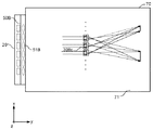
図1は、一実施形態における表示装置10を、空間上に形成される像と共に概略的に示す。実施形態の説明に用いる図面は、分かり易く説明することを目的として、概略的又は模式的である場合がある。また、図面は、実際のスケールで描かれていない場合がある。また、立体像を含む図面は、空間に形成される像の位置を分かり易く示すために、必ずしも観察者の位置から見た場合の図ではなく、観察者とは異なる位置から見た図を示す場合がある。
FIG. 1 schematically shows a
表示装置10は、光を出射する出射面71を有する。表示装置10は、出射面71から出射する光によって、空間中に立体像としての像6を形成する。像6は、ユーザによって、立体的に認識される。なお、立体像とは、表示装置10の出射面71とは異なる位置にあるように認識される像をいう。立体像とは、例えば、表示装置10の出射面71から離れた位置に認識される2次元像も含む。つまり、立体像とは、立体的な形状として認識される像だけでなく、表示装置10の表示面上とは異なる位置に認識される2次元的な形状の像も含む概念である。本実施形態において、立体像6は、出射面71よりz軸プラス側に位置する面200内の「A」の字の像である。面200は、xy面に平行な面である。
The
表示装置10は、導光板70と、光源20と、入射光調節部50とを備える。導光板70は、透明で屈折率が比較的に高い樹脂材料で成形される。導光板70を形成する材料は、例えばポリカーボネート樹脂(PC)、ポリメチルメタクリレート樹脂(PMMA)、ガラス等であってよい。
The
導光板70は、出射面71とは反対側の背面72とを有する。導光板70は、導光板70の四方の端面である端面73、端面74、端面75及び端面76を有する。端面74は、端面73とは反対側の面である。端面76は、端面75とは反対側の面である。光源20からの光は、端面73を介して導光板70に入射する。導光板70は、光源20からの光を出射面71に平行な面内で面状に広げて、端面73から端面74に向かう方向に導く。
The
実施形態の説明において、x軸、y軸及びz軸の右手系の直交座標系を用いる場合がある。z軸方向を、出射面71に垂直な方向で定める。背面72から出射面71への向きをz軸プラス方向と定める。また、y軸方向を、端面73に垂直な方向で定める。端面73から端面74への向きをy軸プラス方向と定める。x軸は、端面75及び端面76に垂直な方向であり、端面75から端面76への向きをx軸プラス方向と定める。なお、記載が冗長にならないよう、xy平面に平行な面のことをxy面、yz平面に平行な面のことをyz面、xz平面に平行な面のことをxz面と呼ぶ場合がある。
In the description of the embodiment, a right-handed orthogonal coordinate system of the x axis, the y axis, and the z axis may be used. The z-axis direction is determined in a direction perpendicular to the
光源20は、発光ダイオード(LED)を含む。光源20からの光は、入射光調節部50において調整されて、導光板70への入射光として端面73に入射する。
The
導光板70の背面72には、光偏向部30a、光偏向部30b及び光偏向部30cを含む、互いに異なる位置に設けられた複数の光偏向部30が設けられている。光偏向部30は、xy面内において2次元的に設けられる。例えば、光偏向部30は、xy面内においてマトリクス状に設けられる。光偏向部30には、導光板70によって導かれている光が入射する。
On the
光偏向部30a、光偏向部30b及び光偏向部30cは、それぞれ導光板70内を伝播する光を偏向して、それぞれ立体像6を描く光を出射面71から出射させる。具体的には、光偏向部30aは、立体像6の各位置に向かう光を、出射面71から出射させる。光偏向部30aは、導光板70によって導かれている光を偏向してxy面内及びyz面内で広げて、立体像6の各位置に向かわせる。図1には、光偏向部30aからの光が、立体像6のいくつかの位置に向けて広がっていく様子が示されている。光偏向部30b及び光偏向部30c並びに光偏向部30の他の光偏向部30のそれぞれも同様である。光偏向部30のそれぞれは、背面72内において微小な領域を占める。光偏向部30のそれぞれは、立体像6をxy面内に投影した場合に占める面積より小さい。立体像6は、それぞれが立体像6内の各位置に向けて光を広げる多数の光偏向部30からの光によって、形成される。すなわち、多数の光偏向部30からの光が、立体像6から発散する方向の光を形成する。なお、立体像6を形成する光は、同一直線上にない少なくとも3つの光偏向部30によって提供されてよい。すなわち、光偏向部30のそれぞれは、光偏向部30のそれぞれに入射した光を、立体像6に応じた強度分布の光に2次元的に広げて出射面から出射させる。これにより、同一直線上にない3つ以上の光偏向部30からの光が、立体像6に結像する。このようにして、表示装置10は空間上に立体像を投影する。表示装置10によれば、同一直線上にない複数の光偏向部30からの光束の集まりによって、立体像6から発散する光束を観察者側に提供できる。そのため、観察者はx軸方向及びy軸方向のどちらの方向から見ても立体像6を認識できる。
The
図2は、表示装置10のyz平面の断面を概略的に示す。図3は、光偏向部30が有する光素子31の一例を概略的に示す。
FIG. 2 schematically shows a cross section of the
光源20は、例えばLED21を有する。LED21は、x軸方向に沿って複数設けられる。LED21の出射光の光軸は、出射面71に対して角度θをなす。例えば、LED21の出射光の光軸と、出射面71とがなす狭角θは、約20°である。LED21の出射光は、入射光調節部50に入射する。
The
入射光調節部50は、レンズ51を有する。レンズ51は、x軸方向に沿って、複数のLED21に対応して1対1に設けられる。レンズ51のそれぞれは、対応するLED21の出射光の光軸に沿う方向の光の広がりを小さくする。レンズ51は、LED21からの出射光を平行光に近づける。例えば、レンズ51は、LED21からの出射光のxy面内における広がり角を低減する。また、レンズ51は、LED21からの出射光のyz面内における広がり角を低減する。これにより、導光板70には、平行光により近づけた光を入射することができる。
The incident
これにより、xy面内において、導光板70によって導かれて導光板70内の各位置を通過する光束は、導光板70内の各位置と光源20とを結ぶ方向を中心として、所定値より小さい角度で各位置から広がりながら進む光束となる。本明細書において、導光板内又は導光板外のある点を通過して進む光束をその点から出力された光とみなした場合の光の広がりのことを、単に「光の広がり」等と呼ぶ。また、その光の広がりの角度のことを、単に「広がり角」等と呼ぶ。広がり角とは、角度方向の光強度分布において、光強度が最大値の半分となる角度の幅(半値全幅)であってよい。導光板70によって導かれている光の広がり角は、5°以下であってよい。光の広がり角は、望ましくは1°未満であってよい。xy面内に投影した場合における光の広がり角が、5°以下であってよく、望ましくは1°未満であってよい。また、yz面内に投影した場合における光の広がり角も、5°以下であってよく、望ましくは1°未満であってよい。
Thereby, in the xy plane, the light beam guided by the
図2及び図3に示されるように、光偏向部30aは反射面40aを有する。また、光偏向部30aは、反射面40bと、反射面40cと、反射面40dと、反射面40eとを有する。反射面40は、光を偏向する偏向面として機能する光学面の一例である。反射面40a、反射面40b、反射面40c、反射面40d及び反射面40eは、異なる方向を向く曲面である。なお、上述したように、LED21の光軸を出射面71に対してyz面内で角度θ傾けて設けている。そのため、導光板70への入射光が平行光に近い場合でも、入射光の光軸がy軸に平行である場合と比べて、出射面71と背面72とで反射を繰り返しながら導光板70内を伝搬する光量を増やすことができる。したがって、入射光の光軸がy軸に平行である場合と比べて、反射面40に入射する光量を増やすことができる。
As shown in FIGS. 2 and 3, the
反射面40aは、反射面40aに入射した光を、反射面40aの入射位置に応じて、出射面71から異なる出射角で出射させる。反射面40aは、反射面40aに入射した光を、立体像6のうちの辺61の範囲に広げる。本実施形態において、辺61は、y軸に平行な辺である。反射面40aからの反射光は、辺61が存在する方向に向かい、反射面40aから辺61が存在しない方向に向かう光は実質的に存在しない。したがって、反射面40aから反射光は、yz面内において、反射面40aから辺61に向かう角度にのみ実質的に反射光を分布させる。このように、yz面内において、反射面40aは、入射した光を角度方向に強度変調して出射する。反射面40aは曲面であるので、反射面40aへの入射光が平行光である場合でも、像を描画する線を形成するための光を提供することができる。
The
また、反射面40bは、反射面40bに入射した光を反射して、反射した光を立体像6の辺62の範囲に広げる。辺62は、Aの文字を形成するy軸マイナス側の辺のうち、辺61との交点と、最もx軸プラス側の端点との間の辺である。また、反射面40cは、反射面40cに入射した光を反射して、反射した光を立体像6の辺63の範囲に広げる。辺63は、Aの文字を形成するy軸プラス側の辺のうち、辺61との交点と、x軸方向で最もプラス側の端点との間の辺である。反射面40dは、反射面40dに入射した光を反射して、反射した光を立体像6の辺64の範囲に広げる。辺64は、Aの文字を形成するy軸マイナス側の辺のうち、辺61との交点と、最もx軸マイナス側の端点との間の辺である。また、反射面40eは、反射面40eに入射した光を反射して、反射した光を立体像6の辺65の範囲に広げる。辺65は、Aの文字を形成するy軸プラス側の辺のうち、辺61との交点と、最もx軸方向マイナス側の端点との間の辺である。反射面40b、反射面40c、反射面40d及び反射面40eはいずれも曲面であるので、各反射面40への入射光が平行光である場合でも、像を描画する線を形成するための光を提供することができる。
The reflecting
このように、反射面40aは、入射した光を、少なくともz軸方向に辺61の像に応じた強度分布を持つ光に広げて出射させる。反射面40bは、入射した光を、少なくともx軸方向に辺62の像に応じた強度分布を持つ光に広げて出射させる。反射面40cは、入射した光を、少なくともx軸方向に辺63の像に応じた強度分布を持つ光に広げて出射させる。反射面40dは、入射した光を、少なくともx軸方向に辺64の像に応じた強度分布を持つ光に広げて出射させる。反射面40eは、入射した光を、少なくともx軸方向に辺65の像に応じた強度分布を持つ光に広げて出射させる。このように、光偏向部30aは、立体像6における線に向けて反射する複数の反射面を持ち、入射した光を、立体像6に応じて2次元的又は2方向に強度変調して、出射面71から出射させる。これにより、1つの光偏向部30aが、立体像6の実質的に全体を通過する光束を提供する。
Thus, the reflecting
光偏向部30bは反射面41bを有する。反射面41bは、反射面40aと同様に、反射面41bに入射した光を、反射面41bの入射位置に応じて、出射面71から異なる出射角で出射する。具体的には、反射面41bは、反射面41bで反射した光を、立体像6のうちの辺61の範囲に広げる。なお、図3では、反射面40a及び反射面41bについてのみ示したが、光偏向部30のそれぞれは、入射した光を辺61の範囲に広げる反射面を有する。また、光偏向部30のそれぞれは、光偏向部30aと同様に、立体像6における線に向けて反射する複数の反射面を持つ光素子を持つ。そして、光偏向部30のそれぞれは、入射した光を、立体像6に応じて2次元的又は2方向に強度変調して、出射面71から出射させる。このように、光偏向部30のぞれぞれは、立体像6の実質的に全体を通過する光束を提供する。
The
なお、出射面71からの出射光は、実際には、出射面71において屈折する。そのため、光偏向部30は実際には、出射面71における屈折を考慮して設計される。しかし、本実施形態では、分かり易く説明することを目的として、出射面71で屈折が生じないとして説明する。
Note that light emitted from the
図4は、特定の観察位置に向かう光を提供する光偏向部30を模式的に示す。例えば、辺62を形成する光は、光偏向部30e内の特定の反射面と、光偏向部30f内の特定の反射面からの光によって提供され、光偏向部30d及び光偏向部30gによっては提供されない。このように、特定の観察位置から見た場合、立体像6の特定の部位は、複数の光偏向部30内のうちの特定の光偏向部30内の特定の部位からの光によって形成される。
FIG. 4 schematically shows a
表示装置10によれば、xy面内に2次元的に設けられた複数の光偏向部30のそれぞれが、立体像6の各部位を通過する光を提供する。そのため、立体像を視認できる範囲が広がる。また、xy面内の特定箇所から、立体像6全体の部位を通過する光を提供できるので、立体像を点ではなく面で形成し得る。
According to the
図5は、光偏向部30の変形例としての光偏向部30Aを模式的に示す斜視図である。光偏向部30Aは、全体として凸形状の反射面を持つ。光偏向部30Aは、導光板70の背面72に設けられる。光偏向部30Aの凸形状の反射面は、導光板70内を導光する光を偏向して、立体像6を包含する面200を通過する光束が出射面71から出射されるように、形成される。
FIG. 5 is a perspective view schematically showing an
光偏向部30Aにおいて、「A」の文字に対応する部分を除いて、反射防止膜110が形成されている。光偏向部30Aにおいて、反射防止膜110が形成された部位に入射した光は実質的に反射しない。光偏向部30Aにおいて反射防止膜110が形成されていない部位に入射した光だけが実質的に反射する。これにより、光偏向部30Aは、入射した光を偏向して、Aの字の立体像6を通過する光束を出射面71から出射させる。反射防止膜110は、例えば、背面72において「A」の文字に対応する領域を除いて黒塗料を塗ることによって形成されてよい。反射防止膜110は、「A」の文字に対応する領域を除いて黒塗料を印刷することによって形成されてよい。導光板70に凸部を形成した後に黒塗料を印刷することで光偏向部30Aを形成できるので、光偏向部の製造が容易になる。
In the
図6は、光偏向部30の変形例としての光偏向部30Bを模式的に示す。図6(a)は、光偏向部30Bの斜視図であり、図6(b)は、C−C部のyz断面である。光偏向部30Bは、「A」の文字に対応する部分領域に形成された複数の反射面120を持つ。「A」の文字に対応する部分領域以外の領域には、反射面は形成されていない。光偏向部30Bにおいて反射面120が形成されていない領域に入射した光は実質的に反射しない。一方、光偏向部30Bは、反射面120が形成された部位に入射した光を偏向させて、立体像6を通過する光束を出射面71から出射させる。
FIG. 6 schematically shows an
図7は、光偏向部30の変形例としての光偏向部30Cを模式的に示す。光偏向部30Cは、別個の位置に設けられた複数の光素子31Cを有する。各光素子31Cは、それぞれ単一平面の反射面を持つ。各光素子31Cがそれぞれ有する反射面は、入射した光を、立体像6のうちの互いに異なる点に向けて光を反射する。
FIG. 7 schematically shows an
なお、光素子31は、全て別個に設けられてよいし、一部が接して設けられてもよい。また、光素子31の配置パターンは、光偏向部30が設けられる位置によって異なってよい。
Note that the
図8(a)は、光偏向部30の変形例としての光偏向部30Dを模式的に示す断面図である。導光板70の背面72には、全体として複数の反射面が一様に形成されている。
FIG. 8A is a cross-sectional view schematically showing an
背面72には、光学部材140が設けられる。光学部材140は、導光板70と屈折率が実質的に同じ材料で形成されている。光学部材140が背面72と対向する面には、背面72に形成された反射面と接する光学面を持つ。光学部材140は、背面72のうち、立体像6の「A」の文字に対応しない領域以外の領域に設けられ、立体像6の「A」の文字に対応する領域には設けられていない。光偏向部30Dは、背面72に形成された反射面のうち、光学部材140が設けられていない部分の反射面によって提供される。
An
背面72のうち、光学部材140と接した領域に入射した光は、背面72を通過する。すなわち、光学部材140と接した領域に入射した光は、出射面71から出射する向きには偏向されない。一方、背面72のうち光学部材140と接していない領域に入射した光は偏向されて出射面71から出射し、立体像6の各部位を通過する光束となる。
Light incident on the area of the
図8(b)は、光偏向部30の変形例としての光偏向部30Eを模式的に示す断面図である。導光板70の背面72には、全体として複数の反射面が形成されている。
FIG. 8B is a cross-sectional view schematically showing an
背面72には、光学部材170が設けられる。光学部材170は、導光板70と屈折率が実質的に同じ材料で形成されている。光学部材170が背面72と対向する面には、背面72に形成された反射面と接する光学面を持つ。光学部材170のうち、立体像6の「A」の文字に対応する領域には、反射膜160が設けられている。立体像6の「A」の文字に対応する領域以外の領域には、反射膜は設けられていない。光偏向部30Eは、背面72に形成された反射面のうち、光学部材170に設けられた反射膜160と接する部分の反射面によって提供される。
An
背面72のうち、反射膜160と接していない領域に入射した光は、背面72を通過する。すなわち、反射膜160と接していない領域に入射した光は、出射面71から出射する向きには偏向されない。一方、背面72のうち反射膜160と接する領域に入射した光は偏向されて出射面71から出射し、立体像6の各部位を通過する光束となる。なお、反射膜160は、銀蒸着膜、アルムニウム蒸着膜、銀めっき膜、クロムめっき膜等であってよい。光偏向部30Eのそれぞれにおいて、反射膜160の反射率は、対応する像の位置によって互いに異なってよい。これにより、輝度に違いを持つ像を形成することができる。また、反射膜160は、特定の色を選択的に反射してよい。これにより、色を持つ像を形成することができる。また、光偏向部30Eのそれぞれにおいて、反射膜160が選択的に反射する光の色は、対応する像の位置によって互いに異なってよい。これにより、複数の色を持つ像を形成することができる。なお、導光板70及び光学部材170を、1つの導光板とみなすことができる。この場合、複数の光偏向部30は、導光板70の内部に設けられることになる。
Light that has entered a region of the
図8(c)は、光偏向部30の変形例としての光偏向部30Fを模式的に示す断面図である。導光板70の背面72には、立体像6の「A」の文字に対応する領域に、光学部材190が設けられる。光学部材190は、背面72に接する面の反対側の面に、複数の反射面を有する。光学部材190に入射した光は、複数の反射面によって偏向されて、出射面71から出射し、立体像6の各部位を通過する光束となる。
FIG. 8C is a cross-sectional view schematically showing an
図9、図10(a)、図10(b)及び図10(c)は、光偏向部30Aの変形例としての光偏向部30Gを形成する方法を説明する図である。光偏向部30Gは、フレネルレンズの一部によって提供される。
9, FIG. 10A, FIG. 10B, and FIG. 10C are diagrams for explaining a method of forming the
導光板70の背面72には、フレネルレンズを形成する光学面を、光偏向部30単位で設ける。図10(a)及び図10(b)は、光偏向部30のうちの1つの光偏向部30Gに、フレネルレンズが形成された状態を示す。光偏向部30のそれぞれのフレネルレンズは、導光板70内を導光する光を偏向して、立体像6を包含する面200を通過する光束が出射面71から出射されるように、形成される。
An optical surface for forming a Fresnel lens is provided on the
続いて、図10(c)に示されるように、導光板70の背面72側に、立体像6の「A」の字に対応する領域以外の領域に、反射防止膜210が形成される。例えば、「A」の文字に対応する領域以外の領域に黒塗料を印刷することによって反射防止膜210を形成してよい。これにより、「A」の字に対応するフレネルレンズの一部の領域に入射した光のみが実質的に偏向されて、立体像6の位置を通過する光束となって、出射面71から出射される。導光板70にフレネルレンズの光学面を形成した後に黒塗料を印刷することで光偏向部30を形成できるので、光偏向部の製造が容易になる。
Subsequently, as shown in FIG. 10C, an
図11は、表示装置10の変形例としての表示装置10Aの一例を模式的に示す。表示装置10Aは、出射面71とは反対側の空間に擬似的に立体像を投影する。ここでは、出射面71に平行な面240内に位置する立体像を形成する場合を取り上げて説明する。
FIG. 11 schematically illustrates an example of a
図11には、互いに異なる光偏向部30に属する反射面42a及び反射面42bが示されている。図11の辺61Aは、立体像を形成する1つの線である。例えば、辺61Aは、立体像6の辺61に対応する。
FIG. 11 shows a reflecting
反射面42aに入射した光は、反射面42aに入射する位置によって、異なる角度で偏向されて出射面71から出射する。具体的には、反射面42aは、反射面42aに対して辺61Aが対称な辺66の位置に向かう光を出射面71から出射させる。例えば、反射面42aは、入射した光を、辺62のy軸マイナス側の端点と光の入射点とを結ぶ線に沿う方向に反射する。また、反射面42aは、入射した光を、辺62のy軸プラス側の端点と光の入射点とを結ぶ線に沿う方向に反射する。このように、反射面42aは、辺61A上の任意の点と反射面42aとを結ぶ方向の光束を提供できる。これにより、反射面42aは、辺61Aから生じる光束と同様の光束を提供できる。反射面42bも同様に、辺61A上の点と反射面42bとを結ぶ方向の光束を提供できる。このように、出射面71とは反対側の空間の像を形成する場合、光偏向部に対して像が点対称をなす位置に出射光が向かうように、光偏向部の反射面を形成すればよい。背面72側の空間に立体像を形成する場合も、出射面71側の空間に立体像6を形成する場合と同様に、背面72側の立体像に応じた強度分布の光を出射する3つ以上の光偏向部からの光によって、背面72側の立体像から発散する方向の光を形成する。このように、表示装置10Aによれば、2次元的に配置された複数の光偏向部からの光束の集まりによって、背面72側の立体像から発散する方向の光束を観察者側の空間に提供できる。
The light incident on the reflecting
以上において、表示装置10および表示装置10Aが、出射面71に平行な面内に形成される立体像を提供する場合を取り上げて説明した。しかし、立体像を形成する位置は、出射面71に平行な面内に限られない。
The case where the
また、上述したように、光偏向部30は、xy面内においてマトリクス状に配列される。例えば、光偏向部30は、x軸方向に等ピッチで設けられるとともに、y軸方向にも等ピッチで設けられる。光偏向部30のx軸方向のピッチは、y軸方向のピッチと同じであってよいし、異なってもよい。光偏向部30のx軸方向のピッチは、y軸方向のピッチより小さくてよい。光偏向部30のx軸方向のピッチを、y軸方向のピッチより小さくした場合には、x軸方向における立体像6を形成する点の密度が高まる。そのため、立体像6を形成する複数の点がx軸方向につながって、線のように認識され易くなる。これにより、観察者は線の両端を容易に認識できるので、立体像6の形状を認識し易くなる。
Further, as described above, the
また、光偏向部30のピッチは、xy面内で異なってもよい。光偏向部30のピッチをxy面内で異ならせることで、立体像6の解像度を領域毎に調節することができる。また、光偏向部30は、周期的に設けられていなくてもよい。光偏向部30は、xy面内でランダムに設けられてよい。なお、観察者によって表示装置10が透明と認識されるようにするためには、光素子31のパターン密度は、50%以下であることが望ましい。光素子31のパターン密度は、10%以下であることがより望ましい。
Further, the pitch of the
図12(a)は、光偏向部30をストライプ状に設けた配置例を模式的に示す。この配置例では、光偏向部30は、x軸方向及びy軸方向に整列して設けられるが、光偏向部30のx軸方向のピッチは、光偏向部30のy方向のピッチより小さい。
FIG. 12A schematically shows an arrangement example in which the
図12(b)は、光偏向部30をジグザグ状に設けた配置例を模式的に示す。例えば、x軸方向を「行」とした場合、各行における光偏向部30のピッチは同一である。y軸方向に隣接する光偏向部30の行の間では、光偏向部30はx軸方向の位置がシフトして設けられる。例えば、隣接する行の間における光偏向部30のx軸方向のシフト量は、行方向の光偏向部30のピッチの半分である。
FIG. 12B schematically shows an arrangement example in which the
図13は、光素子31の形状の他の例を模式的に示す。図13(a)は、光素子31の斜視図を示す。図13(b)は、反射面40をxy面に投影した場合を示す。反射面40をxy面に投影した場合、反射面40の外形を画定するy軸プラス方向の外形線及びy軸マイナス方向の外形線は、同心円の円弧を持つ。なお、xy面に投影した反射面40のy軸マイナス側の外形線を前側外形線と呼び、y軸プラス方向の外形線を後側外形線と呼ぶ場合がある。反射面40の前側外形線及び後側外形線は、同心円の円弧である。
FIG. 13 schematically shows another example of the shape of the
図13(a)及び図13(b)に示す光素子31をzy面に平行な平面で切断した場合、反射面40との交線は直線である。しかし、前側外形線及び後側外形線は曲線であるので、図13の反射面40は曲面である。そのため、像の少なくとも一部を形成する線又は面を形成するための光を、1つの反射面40によって提供することができる。
When the
図14は、xy面内における光素子31の配置例を模式的に示す。図14(a)は、光偏向部30において、複数の光素子31がy軸方向に沿って整列して設けられた配置例を示す。図14(b)は、図14(a)の変形例として、y軸方向に整列した光素子31をy軸方向に沿って順に見た場合に、x軸方向に一定量ずつシフトして設けた配置例を示す。図14(c)は、x軸方向に1つの光素子31として連続して設けられた配置例を示す。図14(c)は、x軸方向に隣接し合う光素子の端部を接続して、1つの光素子として設けたものである。図14(c)において点線で示す位置が、隣接し合う光素子のx軸方向の端部に対応する。
FIG. 14 schematically shows an arrangement example of the
図15は、光素子31の反射面の形状の他の例を模式的に示す。図15(a)及び図15(b)は、xy面内に投影した反射面40の形状を示す。図15(a)に示す反射面40は、前側外形線及び後側前側外形線が第1の曲率の同心円の円弧である反射面部分と、前側外形線及び後側前側外形線が第2の曲率の同心円の円弧である反射面部分とがx軸方向に連続する形状を持つ。図15(b)に示す反射面40は、前側外形線及び後側前側外形線が同心円の円弧である反射面を分割して、複数の部分に分離して設けたものである。
FIG. 15 schematically shows another example of the shape of the reflecting surface of the
図16は、光素子31の反射面の形状の他の例を模式的に示す。図16(a)は、光素子31の斜視図を示す。図16(b)は、光素子31の反射面40をxy面に投影した場合を示す。光素子31は、法線方向が互いに異なる3つの平面で形成される。反射面40をxy面に投影した場合、前側外形線及び後側前側外形線はそれぞれ、延伸方向が異なる3つの折れ線で形成される。図16に示す反射面40は平面であるので、各反射面40に入射した光は、互いに異なる3つの方向に向かう。そのため、図16に示す光素子31は、像の一部である3点を形成するための光を提供することができる。
FIG. 16 schematically shows another example of the shape of the reflecting surface of the
図17は、光素子31の反射面の形状の他の例を模式的に示す。図17(a)及び図17(b)に示す光素子31の反射面40は、図13(a)に示す光素子31と異なり、反射面40のz軸プラス側の縁部のz軸方向の高さが異なる。反射面40をxz面に投影した場合、z軸プラス側の縁部は、x軸方向に連続的に変化する。yz平面に平行な面で反射面40を切断した場合の反射面40の直線の長さは、x軸方向に沿って変化する。そのため、反射面40による反射光の強度は、x軸方向に沿って変化する。そのため、図17(a)及び図17(b)に示す光素子31によれば、輝度がx方向に変化する線の像を形成するための光を提供することができる。
FIG. 17 schematically shows another example of the shape of the reflection surface of the
図17(c)は、xy面内における光素子31の配置例を模式的に示す。光素子31はそれぞれ、前側外形線及び後側前側外形線が同心円の円弧である曲面の反射面(例えば、反射面41a)を持つ複数の光素子と、平面の反射面(例えば、反射面41b)を持つ光素子とを含む。平面の反射面を持つ光素子は、曲面の反射面を持つ光素子より、単位面積あたりで比較的に高い強度の反射光を提供できる。そのため、図17(c)に示すような光素子の配置によれば、平面の反射面から出射される方向だけ光の強度が高まる。これにより、輝度が比較的に高い点を持つ像を形成するための光を提供することができる。図17(a)、図17(b)及び図17(c)に示す光素子31によれば、入射した光を、強度分布が角度方向に連続的又は段階的に変化する光に広げて、出射面71から出射させることができる。
FIG. 17C schematically shows an arrangement example of the
図18は、反射面40の面積による出射光量の違いを説明する図である。図18(a)は、反射面40をxy平面に投影した場合の形状を示す。図18(a)に示す3つの反射面は、外形線の曲率が互いに異なり、y軸方向の長さが互いに異なる。y軸方向の長さは、yz平面に平行な面と反射面40とが交わる直線の長さに比例する。yz平面に平行な面と反射面40との交線の直線の長さが長いほど、出射光量が大きくなる。図18(a)に示されるように、基準となる反射面による出射光量を1とすると、交線の長さが2倍の反射面からは2倍の出射光量が得られ、像における対応する部位の輝度も2倍となる。また、交線の長さが4倍の反射面からは、4倍の出射光量が得られ、像における対応する部位の輝度も4倍となる。このように、交線の長さが異なる反射面を持つ光素子によって、像の領域毎に輝度を調節することが可能になる。一般に、交線の長さがn種類の複数の光素子を用いれば、少なくともn階調の階調表示を行うことが可能になる。交線の長さが任意の基数(例えば、2)の冪となるn種類の複数の光素子の組み合わせによって、2n階調の階調表示を行うことが可能になる。ここで、nは2以上の任意の正の数である。図18に示すように面積が異なる反射面40を用いることで、入射した光を、像の位置に応じて階調が連続的又は段階的に変化する光に広げて、出射面71から出射させることができる。なお、階調表示を行うことができる複数の導光板を用いて、各導光板に互いに異なる色(例えば、赤、青及び緑の3色)の光を入射することによって、カラー表示を行うこともできる。
FIG. 18 is a diagram for explaining a difference in the amount of emitted light depending on the area of the reflecting
図18(b)は、交線の長さが異なる複数の反射面を組み合わせて、出射光量を調節する場合の配置例を示す。例えば、出射光量が1の反射面と出射光量が2の反射面とを組み合わせることで、出射光量を3にすることができる。この反射面から像の同じ位置又は近傍の位置に向けて光が出射されるようにすることで、像の対応する部分の輝度を3倍にすることができる。図18(a)及び図18(b)に示されるように、交線の長さが3種類の光素子を組み合わせて、8階調の階調表示を行うことが可能になる。 FIG. 18B shows an arrangement example in the case of adjusting the amount of emitted light by combining a plurality of reflecting surfaces having different lengths of intersecting lines. For example, the amount of emitted light can be made 3 by combining a reflective surface with an emitted light amount of 1 and a reflective surface with an emitted light amount of 2. By emitting light from the reflecting surface toward the same position of the image or in the vicinity thereof, the luminance of the corresponding portion of the image can be tripled. As shown in FIG. 18A and FIG. 18B, it is possible to perform gradation display of 8 gradations by combining three types of optical elements having intersection lengths.
図18(c)は、反射面40のz方向プラス側の縁部からxy面内に下ろした垂線の高さhを示す。反射面の高さhを異ならせることによって、出射光量を異ならせることもできる。
FIG. 18C shows the height h of the perpendicular line dropped from the edge of the reflecting
なお、表示装置10では、レンズ51を有する入射光調節部50によって、光の広がり角が小さい入射光を得ることができる。入射光調節部50を備えずに、上述した光の広がり角を満たす光を出射する光源を用いてもよい。係る光源として、レーザダイオード等のレーザ光源を用いてよい。また、1つのLED21を光源として用いて、1つのLED21からの光を放射状に広げることによって、上述した光の広がり角を満たす光を得てよい。LED21の出射開口を絞ることによって、上述した光の広がり角を満たす光を得てよい。また、LED等の単一の光源と端面73との間に、導光板70の端面73に対向する出射面を持つ導光板を介在させて、当該導光板からの出射光を、端面73に入射してよい。
In the
図19は、入射光調節部50の変形例としての導光板53及びレンズ51を模式的に示す。LED21からの光は、レンズ51によってx軸方向に沿う方向に実質的に平行化され、導光板53に入射される。導光板53は、入射した光をx軸に沿う方向に伝播する。導光板53の出射面は、端面73に対向して設けられている。導光板53を伝播する光は、導光板53の出射面とは反対側の面の一部に形成された複数の反射面で反射して、導光板53の出射面から、xy面内で実質的に平行な光束が出射される。これにより、端面73からは、y軸方向に沿う平行光束が入射されて、導光板70に入射する。これにより導光板70は、xy面内及びyz面内において広がり角が小さい光を伝播することができる。
FIG. 19 schematically shows a
なお、以上の説明では、導光板70内でのxy面内及びyz面内における光の広がり角を小さくするために、y軸方向に略平行な光を入射光として用いる構成を説明した。xy面内及びyz面内における光の広がり角を小さくするための他の構成として、実質的な点光源を1つ含む光源20と、当該点光源からの光のyz面内における光の広がりを小さくする入射光調節部50とを用いてもよい。この場合、入射光調節部50として、yz面内において、y軸プラス方向及びy軸マイナス方向の少なくとも一方に突出した形状を有するシリンドリカル平凸レンズを用いてよい。
In the above description, a configuration in which light substantially parallel to the y-axis direction is used as incident light in order to reduce the light spread angle in the xy plane and yz plane in the
図20は、表示装置10の変形例としての表示装置10Bの一例を立体像6Bとともに模式的に示す。図21は、表示装置10Bのxy面内の平面図である。表示装置10Bは、xz面に平行な面300に立体像6Bを投影する。
FIG. 20 schematically illustrates an example of a
表示装置10Bは、表示装置10と比較して、導光板70内を伝播する光のyz面内における広がりが大きい。後述するように、入射光調節部50Bは、入射光調節部50と同様に、光源20からの光のxy面内における広がり角を小さくする。しかし、入射光調節部50Bは、光源20からの光のyz面内における広がり角を小さくしない。入射光調節部50Bは、光源20からの光のyz面内における広がり角に実質的に影響を与えない。例えば、入射光調節部50Bが有するレンズ51Bは、xy面内で曲率を持ち、yz面内で曲率を実質的に持たない凸状のシリンドリカルレンズであってよい。レンズ51は、シリンドリカル両凸レンズである。導光板70に入射する光の広がり角について、yz面内に投影した場合の光の広がり角は、xy面内に投影した場合の光の広がり角より大きい。導光板70によって導かれている光をxy面内に投影した場合の光の広がり角は、5°以下であってよい。xy面内における光の広がり角は、望ましくは1°未満であってよい。なお、導光板70内のxy面内における光の広がり角を小さくするための他の構成として、LED等の1つの光源を光源20として適用し、x軸方向に所定幅より小さい開口を持つマスクを入射光調節部50Bとして適用してもよい。
The
表示装置10Bは、光偏向部群330a、光偏向部群330b及び光偏向部群330cを含む複数の光偏向部群を有する。光偏向部群330は、x軸に平行な方向に沿って設けられた複数の光偏向部を有する。例えば、光偏向部群330aは、光偏向部30Baを含む複数の光偏向部30を有する。また、光偏向部群330bは、光偏向部30Bbを含む複数の光偏向部を有する。また、光偏向部群330cは、光偏向部30Bcを含む複数の光偏向部を有する。
The
光偏向部30Baは、入射した光を偏向してxy面内に平行な方向に広げて、出射面71から出射させる。光偏向部30Baによって出射面71から出射した光束は、面300と実質的に線で交差する。図20及び図21に示されるように、光偏向部30Baによって出射面71から2つの光束が出射される。出射した2つの光束は、面300と線351及び線352で交差する。図21に示されるように、光偏向部群330aに含まれるいずれの光偏向部も、光偏向部30Baと同様に、面300と線351及び線352で交差する光束を出射面71から出射させる。線351及び線352は、実質的にxy面に平行な面内にあり、立体像6Bの一部を形成する。このように、光偏向部群330aに属する多数の光偏向部30からの光によって、線351及び線352の像が形成される。なお、線351及び線352の像を形成する光は、x軸方向に沿って異なる位置に設けられた少なくとも2つの光偏向部30によって提供されてよい。すなわち、光偏向部群330aに属する複数の光偏向部30のそれぞれは、複数の光偏向部30のそれぞれに入射した光を、出射面71に平行な面内で、線351及び線352の像に応じた強度分布の光にx軸方向に広げて、出射面71から出射させる。これにより、光偏向部群330aに属し、x軸方向に沿って配置された複数の光偏向部30からの光が、線351及び線352の像に結像する光になる。
The light deflector 30Ba deflects the incident light, spreads it in a direction parallel to the xy plane, and emits it from the
光偏向部30Bbは、入射した光を偏向してxy面内に平行な方向に広げて、3つの光束を出射面71から出射させる。出射面71から出射した3つの光束は、面300と線361、線362及び線363で交差する。光偏向部群330bに含まれるいずれの光偏向部も、光偏向部30Bbと同様に、面300と線361、線362及び線363で交差する光束を出射面71から出射させる。このように、光偏向部群330bに属する複数の光偏向部30のそれぞれは、複数の光偏向部30のそれぞれに入射した光を、出射面71に平行な面内で、線361、線362及び線363の像に応じた強度分布の光にx軸方向に広げて、出射面71から出射させる。これにより、光偏向部群330bに属し、x軸方向に沿って配置された複数の光偏向部30からの光が、線361、線362及び線363の像に結像する光になる。なお、線361、線362及び線363は、実質的にxy面に平行な面内にあり、立体像6Bの一部を形成する。線361、線362及び線363と、線351及び線352とは、面300内においてz軸方向の位置が異なる。
The light deflection unit 30Bb deflects the incident light and spreads it in a direction parallel to the xy plane, and emits three light beams from the
また、光偏向部30Bcは、入射した光を偏向してxy面内に平行な方向に広げて、3つの光束を出射面71から出射させる。出射面71から出射した2つの光束は、面300と線371及び線372で交差する。光偏向部群330cに含まれるいずれの光偏向部も、光偏向部30Bcと同様に、面300と線371及び線372で交差する光束を出射面71から出射させる。このように、光偏向部群330cに属する複数の光偏向部30のそれぞれは、複数の光偏向部30のそれぞれに入射した光を、出射面71に平行な面内で、線371及び線372の像に応じた強度分布の光にx軸方向に広げて、出射面71から出射させる。これにより、光偏向部群330cに属し、x軸方向に沿って配置された複数の光偏向部30からの光が、線371及び線372の像に結像する光になる。なお、線371及び線372は、実質的にxy面に平行な面内にあり、立体像6Bの一部を形成する。線371及び線372と、線351及び線352とは、面300内においてz軸方向の位置が異なる。また、線371及び線372と、線361、線362及び線363とは、面300内においてz軸方向の位置が異なる。
The light deflector 30Bc deflects the incident light and spreads the light in a direction parallel to the xy plane so that three light beams are emitted from the
このように、表示装置10Bによれば、2次元的に配置された複数の光偏向部からの光束の集まりによって、像6Bから発散する光束を観察者側の空間に提供できる。そのため、観察者はx軸方向に沿う広い位置範囲から立体像6Bを認識できる。
As described above, according to the
図22は、表示装置10Bによって投影される面300内の立体像6Bを模式的に示す。このように、表示装置10Bが有する複数の光偏向素子群からの光束は、立体像6Bが形成する面300内において、z軸方向に互いに位置が異なる複数の線を形成する。面300において、複数の光偏向素子群からの光束による複数の線によって、立体像6Bが形成される。
FIG. 22 schematically shows a
なお、表示装置10Bにおいても、表示装置10と同様、光偏向部30を周期的に設けても良いし、周期的に設けなくても良い。また、立体像6B内の輝度を異ならせるために、光偏向部30のx軸方向のピッチを領域毎に異ならせてよい。なお、輝度を調節する他の方法として、光偏向部30の光学面の面積を領域毎に異ならせてもよい。例えば、光偏向部30が有する光学面の高さ及び長さの少なくとも一方を異ならせることによって、領域毎に輝度を調節してよい。表示装置10Bに8階調の輝度差を持たせることで、モノクロまたは単一色の8階調表示を行うことが可能になる。また、8階調の階調表示を行うことができる3つの導光板を用いて、各導光板に互いに異なる色(例えば、赤、青及び緑)の光を入射することによって、フルカラー表示を行うこともできる。
In the
なお、1つの光偏向部群330によって形成される像の輝度は、形成される像の位置からxz面内で単位角度の範囲内に存在する光偏向部30からの光量に比例する。各光偏向部30から出射される光量が同一であるとすると、形成される像の輝度は、単位角度の範囲内に存在する光偏向部30の数に比例する。したがって、輝度が一定の像を形成する場合、光偏向部30のx軸方向のピッチは、それぞれの光偏向部30に対応する像の位置と導光板70との間のz軸方向の距離が長いほど、大きくすることが望ましい。例えば、線351及び線352に対応する光偏向部群330aに属する光偏向部30のピッチは、線351及び線352より導光板70に近い位置の線に対応する光偏向部群330(例えば、光偏向部群330b、光偏向部群330c等)に属する光偏向部30のピッチより、大きいことが好ましい。光偏向部群330のそれぞれに属する光偏向部群330に属する光偏向部30のピッチは、例えば、それぞれの光偏向部30からの光が形成する線の位置と導光板70との間のz軸方向の距離に比例させてよい。これにより、形成される像の位置から見て単位角度の範囲内に存在する光偏向部30の数を同一にすることができるので、像のz軸方向の位置によって光強度の差が大きくなることを抑制できる。
Note that the luminance of an image formed by one light deflection unit group 330 is proportional to the amount of light from the
図23(a)は、光偏向部30Bbの光学面をxy面に投影した形状を模式的に示す。光偏向部30Bbは、円弧状の外形線を持つ光学面380a及び光学面380bを持つ。光学面380a及び光学面380bは、入射した光をxy面内で広げる。光学面380aと光学面380bとの間は、離間して設けられる。光学面380aと光学面380bとが離間した領域は、立体像6Bの像の線が存在しない部分に対応する。
FIG. 23A schematically shows a shape obtained by projecting the optical surface of the light deflector 30Bb onto the xy plane. The light deflection unit 30Bb has an
なお、光学面380aと光学面380bとを連結して設けてもよい。光学面380aの外形線の曲率は光学面380bの外形線の曲率と異なっていてもよい。また、例えば、立体像6Bの明るさがx軸方向に沿って異なる場合、光学面380とyz面との交線の長さをx軸方向に異ならせてもよい。例えば、光学面380の高さを異ならせてよい。また、同一の線を形成する光学面380を複数有してもよい。
Note that the
図22に示されるように連続する線の集合で面状の像を形成する場合、図23に示すように曲面の反射面を持つ光学面380を持つ光要素を用いることで、面状の像を形成するための光をより小数の光要素で提供することが可能になる。 When a planar image is formed by a set of continuous lines as shown in FIG. 22, a planar image is obtained by using an optical element having an optical surface 380 having a curved reflecting surface as shown in FIG. It is possible to provide the light for forming the light with a smaller number of light elements.
図24(a)は、光偏向部30Bbの変形例が有する光要素の光学面をxy面に投影した形状を模式的に示す。図24(b)は、本変形例によって投影される面300内の立体像350を模式的に示す。本変形例は、平面状の4つの光学面360a、光学面360b、光学面360c及び光学面360dを持つ。光学面360a、光学面360b、光学面360c及び光学面360dは、直線状のプリズムによって提供される。各光学面360は、導光板70の背面72と線で交差する。
FIG. 24A schematically shows a shape obtained by projecting the optical surface of the optical element included in the modification of the light deflection unit 30Bb onto the xy plane. FIG. 24B schematically shows a three-
各光学面360は、入射した光を反射する。各光学面360は平面であるので、各光学面360で反射した光は、面300と実質的に点で交差する。具体的には、光学面360aからの光は、面300と実質的に点370aで交差する。光学面360bからの光は、面300と実質的に点370bで交差する。光学面360cからの光は、面300と実質的に点370cで交差する。光学面360dからの光は、面300と実質的に点370dで交差する。このように、各光学面360からの光が面300で交差する点370は、互いに異なる。本変形例によれば、立体像6Bの輪郭線を形成する複数の点を形成する光束が、出射面71から出射される。
Each optical surface 360 reflects incident light. Since each optical surface 360 is a plane, the light reflected by each optical surface 360 substantially intersects the
なお、本変形例では、4つの光学面360をx軸方向に沿って連結して設けられる。そのため、この光要素とxy面との交線は折れ線となる。図24(a)及び図24(b)に示されるように、任意の線の像を形成するために、各光偏向部30において平面形状の複数の反射面の集合が必要となる。
In the present modification, four optical surfaces 360 are connected along the x-axis direction. Therefore, the intersection line between the optical element and the xy plane is a broken line. As shown in FIG. 24A and FIG. 24B, in order to form an image of an arbitrary line, each
なお、光学面360を連結して設けなくてもよい。光学面360の一部を連結して設けてもよいし、全ての光学面360を離間して設けてもよい。例えば、図24(b)のように4点を形成する光要素を提供する場合、3つの光学面360を連結した光要素と、1つの光学面360を持つ光要素とを、離間して設けてよい。他の例では、2つの光学面360を連結した光要素と、2つの光学面360を持つ光要素とを、離間して設けてよい。他の例では、2つの光学面360を連結した光要素と、1つの光学面360を持つ光要素と、1つの光学面360を持つ光要素とを、互いに離間して設けてよい。 Note that the optical surface 360 may not be connected. A part of the optical surface 360 may be connected, or all the optical surfaces 360 may be provided separately. For example, when providing an optical element forming four points as shown in FIG. 24B, an optical element in which three optical surfaces 360 are connected and an optical element having one optical surface 360 are provided apart from each other. It's okay. In another example, an optical element in which two optical surfaces 360 are connected and an optical element having two optical surfaces 360 may be provided apart from each other. In another example, an optical element obtained by connecting two optical surfaces 360, an optical element having one optical surface 360, and an optical element having one optical surface 360 may be provided apart from each other.
図25(a)は、光偏向部30Bbの変形例が有する光要素の光学面をxy面に投影した形状を模式的に示す。図25(b)は、本変形例によって投影される面300内の立体像400を模式的に示す。本変形例は、図23(a)等に関連して説明した光偏向部30Bbの構成に加えて、図24(a)に関連して説明した4つの光学面360の構成を有する。本変形例によれば、立体像は、立体像6Bに加えて、立体像6Bの輪郭線を形成することができる。そのため、立体像6Bの輪郭を強調することができる。これにより、観察者は立体像6Bの形状をはっきりと認識することができる。
FIG. 25A schematically shows a shape obtained by projecting the optical surface of the optical element included in the modification of the light deflection unit 30Bb onto the xy plane. FIG. 25B schematically shows a
図25(c)は、光偏向部30Bbの変形例をxy面に投影した形状を模式的に示す。図25(c)は、図25(a)において、直線状のプリズムによる光学面360を、円弧状プリズムによる光学面380の端に移動させたものに相当する。具体的には、光学面380aのx軸方向マイナス側の端部には、光学面360aが設けられる。光学面380aのx軸方向プラス側の端部には、光学面360bが設けられる。また、光学面380bのx軸方向マイナス側の端部には、光学面360cが設けられる。光学面380bのx軸方向プラス側の端部には、光学面360dが設けられる。このように、x軸に沿う方向において、各光学面380の両端に、立体像の輪郭線の形成を担う光学面360が位置する。なお、本変形例では光学面380の端部と光学面360の端部とを連結しているが、光学面380の端部と光学面360の端部とを離間して設けてもよい。
FIG. 25C schematically shows a shape of a modification of the light deflection unit 30Bb projected on the xy plane. FIG. 25C corresponds to FIG. 25A in which the optical surface 360 by the linear prism is moved to the end of the optical surface 380 by the arc-shaped prism. Specifically, an
図26(a)は、光学面380に生じるダレ440を模式的に示す。ダレ440は、光学面380を導光板70に作成する場合に生じ得る。一般に、ダレが生じた面の向きと、ダレが生じていない面の向きとの差が大きくなると、導光板70を導光される光の広がり角が大きくなってしまう場合がある。
FIG. 26A schematically shows a
図26(a)に示されるように、光学面380の外形線はxy面内において円弧形状を有し、曲率中心が光学面380より光源20側にある。そのため、光学面380において生じたダレ440の面の法線方向450は、光学面380においてダレが生じていない面の法線方向460との差が小さくなる。
As shown in FIG. 26A, the outline of the optical surface 380 has an arc shape in the xy plane, and the center of curvature is closer to the
図26(b)は、光学面380からの光束のx方向の強度分布を模式的に示す。図26(b)に示されるように、光学面380においてダレが生じていない部分からの光束の分布470と、ダレ440からの光束の分布480とは、大部分が重なる。そのため、光学面380からの光束の広がりにダレ440が与える影響は小さい。
FIG. 26B schematically shows the intensity distribution in the x direction of the light beam from the optical surface 380. As shown in FIG. 26 (b), the
図26(c)には、外形線の曲率中心が光学面より光源20とは反対側にある光学面382を模式的に示す。この場合、ダレ442が生じた面の法線452の方向と、光学面382においてダレ442が生じていない面の法線462の方向との差が大きくなる。
FIG. 26C schematically shows an optical surface 382 in which the center of curvature of the outline is on the side opposite to the
図26(d)は、光学面380からの光束のx方向の強度分布を模式的に示す。図26(d)に示されるように、ダレ442からの光束の分布482の一部は、光学面380においてダレが生じていない部分からの光束の分布472より外にある。そのため、光学面380からの光束の広がりにダレ442が与える影響は大きい。以上に説明したように、光学面380の曲率中心が光学面380より光源20側にあることが好ましい。
FIG. 26D schematically shows the intensity distribution in the x direction of the light beam from the optical surface 380. As shown in FIG. 26 (d), a part of the
図27は、表示装置10Bの変形例としての表示装置10Cの一例を模式的に示す。表示装置10Cは、出射面71とは反対側の空間に擬似的に立体像を投影する。ここでは、出射面71に直交する面500内に位置する立体像を形成する場合を取り上げて説明する。
FIG. 27 schematically illustrates an example of a
表示装置10Cは、光偏向部群330Ca、光偏向部群330Cb及び光偏向部群330Ccを含む複数の光偏向素子群を有する。
The
光偏向部30Caは、入射した光を偏向してxy面内に平行な方向に広げて、2つの光束を出射面71から出射させる。光偏向部30Caによって出射面71から出射した光束の一方は、面500の線551上の点と光偏向部30Caとを結ぶ方向の光束である。光偏向部30Caによって出射面71から出射した光束の他方は、面500の線552上の点と光偏向部30Caとを結ぶ方向の光束である。光偏向部30Caと同様に、光偏向部群330Caに含まれるいずれの光偏向部も、面500の線551上の点とそれぞれの光偏向部30とを結ぶ方向の光束と、面500の線552上の点とそれぞれの光偏向部30とを結ぶ方向の光束とを、出射面71から出射させる。線551及び線552は、実質的にxy面に平行な面内にあり、立体像6Cの一部を形成する。このように、光偏向部群330Caに属する複数の光偏向部30のそれぞれは、複数の光偏向部30のそれぞれに入射した光を、出射面71に平行な面内で、線551及び線552の像に応じた強度分布の光にx軸方向に広げて、出射面71から出射させる。これにより、光偏向部群330Caに属し、x軸方向に沿って配置された複数の光偏向部30からの光が、線551及び線552の像から発散する方向の光になる。
The light deflecting unit 30Ca deflects the incident light and spreads it in a direction parallel to the xy plane so that two light beams are emitted from the
光偏向部30Cbは、入射した光を偏向してxy面内に平行な方向に広げて、3つの光束を出射面71から出射させる。出射面71から出射した3つの光束は、面500の線561上の点と光偏向部30Cbとを結ぶ方向の光束、面500の線562上の点と光偏向部30Cbとを結ぶ方向の光束、及び、面500の線563上の点と光偏向部30Cbとを結ぶ方向の光束である。光偏向部30Cbと同様に、光偏向部群330Cbに含まれるいずれの光偏向部も、面500の線561上の点とそれぞれの光偏向部30とを結ぶ方向の光束と、面500の線562上の点とそれぞれの光偏向部30とを結ぶ方向の光束と、面500の線563上の点とそれぞれの光偏向部30とを結ぶ方向の光束とを、出射面71から出射させる。線561、線562及び線563は、実質的にxy面に平行な面内にあり、立体像6Cの一部を形成する。このように、光偏向部群330Cbに属する複数の光偏向部30のそれぞれは、複数の光偏向部30のそれぞれに入射した光を、出射面71に平行な面内で、線561、線562及び線563の像に応じた強度分布の光にx軸方向に広げて、出射面71から出射させる。これにより、光偏向部群330Cbに属し、x軸方向に沿って配置された複数の光偏向部30からの光が、線561、線562及び線563の像から発散する方向の光になる。
The
また、光偏向部30Ccは、入射した光を偏向してxy面内に平行な方向に広げて、2つの光束を出射面71から出射させる。光偏向部30Ccによって出射面71から出射する2つの光束は、面500の線571上の点と光偏向部30Ccとを結ぶ方向の光束、及び、面500の線572上の点と光偏向部30Ccとを結ぶ方向の光束である。光偏向部30Ccと同様に、光偏向部群330Ccに含まれるいずれの光偏向部も、面500の線571上の点とそれぞれの光偏向部30とを結ぶ方向の光束と、面500の線572上の点とそれぞれの光偏向部30とを結ぶ方向の光束とを、出射面71から出射させる。線571及び線572は、実質的にxy面に平行な面内にあり、立体像6Cの一部を形成する。このように、光偏向部群330Ccに属する複数の光偏向部30のそれぞれは、複数の光偏向部30のそれぞれに入射した光を、出射面71に平行な面内で、線571及び線572の像に応じた強度分布の光にx軸方向に広げて、出射面71から出射させる。これにより、光偏向部群330Caに属し、x軸方向に沿って配置された複数の光偏向部30からの光が、線571及び線572の像から発散する方向の光になる。
The light deflector 30Cc deflects the incident light and spreads the light in a direction parallel to the xy plane so that two light beams are emitted from the
このように、表示装置10Cによれば、2次元的に配置された複数の光偏向部からの光束の集まりによって、像6Cから発散する方向の光束を観察者側の空間に提供できる。なお、表示装置10Cでは、立体像6Cの形成される位置が出射面71とは反対側であり、立体像6Cを形成する面500が出射面71から出射する光束と交差しない。しかし、表示装置10Bも、表示装置10Cと同様に、各光偏向部30が出射面71から出射させる光束は、立体像を形成する線上の点と光偏向部30とを結ぶ方向の光束である。そのため、表示装置10Bに関連して上述した事項と同様の事項を、表示装置10Cに適用できる。そのため、表示装置10Cについての詳細な説明を省略する。
As described above, according to the
図20から図27に関連して、出射面71に直交する面内に形成される立体像を取り上げて説明した。しかし、立体像を形成する位置は、出射面71に直交な面内に限られない。立体像を形成する位置は、出射面71に平行な面内でない限り、どのような位置にあってもよい。
With reference to FIGS. 20 to 27, the three-dimensional image formed in the plane orthogonal to the
また、上述したように、光偏向部30は、xy面内においてマトリクス状に配列される。例えば、光偏向部30は、x軸方向に等ピッチで設けられるとともに、y軸方向にも等ピッチで設けられる。ここで、光偏向部30のx軸方向のピッチは、y軸方向のピッチと同じであってよいし、異なってもよい。光偏向部30のx軸方向のピッチは、y軸方向のピッチより小さくてよい。光偏向部30のx軸方向のピッチを、y軸方向のピッチより小さくした場合には、x軸方向における立体像6を形成する点の密度が高まる。そのため、立体像6を形成する点がx軸方向につながった線のように認識され易くなる。これにより、観察者は線の両端を容易に認識できるので、立体像6の形状を認識し易くなる。
Further, as described above, the
また、光偏向部30のピッチは、xy面内で異なってもよい。光偏向部30のピッチをxy面内で異ならせることで、立体像6の解像度を領域毎に調節することができる。また、光偏向部30は、周期的に設けられていなくてもよい。光偏向部30は、xy面内でランダムに設けられてよい。
Further, the pitch of the
図28(a)は、表示装置10Bの変形例としての表示装置10Dのxy平面図の一例である。表示装置10Dは、端面73に一体に形成されている複数のレンズ51Dを有する入射光調節部50Dを備える点で、表示装置10Bと異なる。レンズ51Dは、xy面内において、端面73からy軸マイナス方向に突出した凸部である。
Fig.28 (a) is an example of xy top view of
図28(b)は、表示装置10Bにおいて、レンズ51Bに代えて、シリンドリカル平凸レンズであるレンズ51BAを用いたものである。レンズ51BAは、xy面内においてy軸プラス方向に突出した形状を有する。なお、レンズ51Bに代えて、xy面内においてy軸マイナス方向に突出した形状を有するシリンドリカル平凸レンズを用いてもよい。
FIG. 28B shows the
また、以上の説明において、光偏向部30の機能を持つ光学面として、直線プリズムや円弧形のプリズムにより提供される光学面や、フレネルレンズを形成する光学面を例示した。その他にも、光偏向部30の機能を持つ光学面として、回折格子等の回折面を適用できる。これらの光学面はいずれも、出射面71に対して傾いている。光偏向部30として回折面を適用する場合、回折面は背面72に設けてもよいし、出射面71に設けてもよい。また、反射、回折の他に、屈折によって光源からの光を偏向する光学面を用いてもよい。図29(a)は、光偏向部30の一部として屈折面43を持つ表示装置10Eのyz断面の一例を模式的に示す。図29(b)は、光偏向部30の一部として屈折面44を持つ表示装置10Fのyz断面の一例を模式的に示す。図29(a)及び図29(b)に示されるように屈折面43は、出射面71に設けられる。
Moreover, in the above description, as an optical surface having the function of the
以上に説明した表示装置10又は表示装置10の変形例によれば、導光板70の出射面に平行な面内に2次元的に設けられた複数の光偏向部のそれぞれが、立体像内の複数の部位の像を形成する光を提供する。そのため、立体像を視認できる範囲が広がる。また、立体像の少なくとも一部を点ではなく面的に形成することができる。
According to the
以上、本発明を実施の形態を用いて説明したが、本発明の技術的範囲は上記実施の形態に記載の範囲には限定されない。上記実施の形態に、多様な変更又は改良を加えることが可能であることが当業者に明らかである。その様な変更又は改良を加えた形態も本発明の技術的範囲に含まれ得ることが、特許請求の範囲の記載から明らかである。 As mentioned above, although this invention was demonstrated using embodiment, the technical scope of this invention is not limited to the range as described in the said embodiment. It will be apparent to those skilled in the art that various modifications or improvements can be added to the above embodiment. It is apparent from the description of the scope of claims that embodiments with such changes or improvements can be included in the technical scope of the present invention.
特許請求の範囲、明細書、及び図面中において示した装置、システム、プログラム、及び方法における動作、手順、ステップ、及び段階等の各処理の実行順序は、特段「より前に」、「先立って」等と明示しておらず、また、前の処理の出力を後の処理で用いるのでない限り、任意の順序で実現しうることに留意すべきである。特許請求の範囲、明細書、及び図面中の動作フローに関して、便宜上「まず、」、「次に、」等を用いて説明したとしても、この順で実施することが必須であることを意味するものではない。 The execution order of each process such as operation, procedure, step, and stage in the apparatus, system, program, and method shown in the claims, the description, and the drawings is particularly “before” or “prior to”. It should be noted that the output can be realized in any order unless the output of the previous process is used in the subsequent process. Regarding the operation flow in the claims, the specification, and the drawings, even if it is described using “first”, “next”, etc. for the sake of convenience, it means that it is essential to carry out in this order. It is not a thing.
6 像
10 表示装置
20 光源
21 LED
30 光偏向部
31 光素子
40、41、42 反射面
43、44 屈折面
50 入射光調節部
51 レンズ
53 導光板
61、62、63、64、65、66 辺
70 導光板
71 出射面
72 背面
73、74、75、76 端面
110 反射防止膜
120 反射面
140 光学部材
160 反射膜
170、190 光学部材
200、240、300、500 面
210 反射防止膜
330 光偏向部群
350 立体像
351、352、361、362、363、371、372、551、552、561、562、563、571、572 線
360 光学面
370 点
380、382 光学面
400 立体像
440、442 ダレ
450、460 法線方向
470、472、480、482 分布
6
30
Claims (14)
前記出射面に平行な面内に2次元的に配置され、それぞれ前記導光板内を伝播する光を偏向して、空間上の像を形成する光を前記出射面から出射させる複数の光偏向部と
を備え、
前記複数の光偏向部のそれぞれが、前記複数の光偏向部のそれぞれに入射した光を、前記出射面に平行な面内で前記導光板の導光方向に直交する方向に前記像に応じた強度分布を持つ光に広げて前記出射面から出射させることによって、前記導光方向に直交する方向に沿って配置された前記複数の光偏向部からの光の集まりによって、前記像から発散する方向の光が形成される
光デバイス。 A light guide plate that propagates light from the light source in a plane parallel to the exit surface;
A plurality of light deflecting units that are two-dimensionally arranged in a plane parallel to the exit surface and deflect the light propagating through the light guide plate to emit the light forming the image on the space from the exit surface. And
Each of the plurality of light deflection units responds to the image with light incident on each of the plurality of light deflection units in a direction perpendicular to the light guide direction of the light guide plate within a plane parallel to the emission surface. A direction that diverges from the image due to a collection of light from the plurality of light deflection units arranged along a direction orthogonal to the light guide direction by spreading the light having an intensity distribution and emitting the light from the emission surface. An optical device in which the light is formed.
前記出射面に平行な面内に2次元的に配置され、それぞれ前記導光板内を伝播する光を偏向して、空間上の像を形成する光を前記出射面から出射させる複数の光偏向部と
を備え、
前記複数の光偏向部のそれぞれが、前記複数の光偏向部のそれぞれに入射した光を、前記像に応じた強度分布の光に2次元的に広げて前記出射面から出射させることによって、同一直線上にない3つ以上の光偏向部からの光の集まりによって、前記像から発散する方向の光が形成される
光デバイス。 A light guide plate that propagates light from the light source in a plane parallel to the exit surface;
A plurality of light deflecting units that are two-dimensionally arranged in a plane parallel to the exit surface and deflect the light propagating through the light guide plate to emit the light forming the image on the space from the exit surface. And
Each of the plurality of light deflection units spreads the light incident on each of the plurality of light deflection units into light having an intensity distribution corresponding to the image and emits the light from the emission surface. An optical device in which light in a direction diverging from the image is formed by a collection of light from three or more light deflection units that are not in a straight line.
請求項1又は2に記載の光デバイス。 2. Each of the plurality of light deflection units includes one or a plurality of sets of deflection surfaces inclined with respect to the emission surface, which are provided on or in the surface of the light guide plate and reflect, refract, or diffract. Or the optical device of 2.
請求項3に記載の光デバイス。 The optical device according to claim 3, wherein at least one of the deflection surfaces has a plurality of planes or curved surfaces facing different directions.
請求項3又は4に記載の光デバイス。 The at least one of the deflection surfaces has a shape of a polygonal line or a curve extending in a direction orthogonal to the light guide direction of the light guide plate when projected onto a plane parallel to the exit surface. 5. The optical device according to 4.
請求項1から5のいずれか一項に記載の光デバイス。 6. The light according to claim 1, wherein at least a part of the plurality of light deflection units has a plurality of deflection surfaces extending in a linear shape when projected onto a plane parallel to the emission surface. device.
請求項1から6のいずれか一項に記載の光デバイス。 At least a part of the plurality of light deflection units includes a plurality of deflection surfaces extending in a curved shape and one or more linear deflection surfaces when projected onto a plane parallel to the emission surface. The optical device according to claim 1.
請求項1又は2に記載の光デバイス。 3. The optical device according to claim 1, wherein at least a part of the plurality of light deflection units has a deflection surface that forms a part of a Fresnel lens disposed at a position corresponding to the image.
請求項1から7のいずれか一項に記載の光デバイス。 8. The device according to claim 1, wherein at least a part of the plurality of light deflection units has one or more deflection surfaces having a shape along one arc when projected onto a plane parallel to the emission surface. The optical device according to one item.
前記光デバイスは、
前記一様に設けられた前記複数の偏向面のうちの一部の偏向面に設けられた光反射材
をさらに備え、
前記一様に形成された前記複数の偏向面のうち、前記光反射材が設けられた偏向面によって、前記複数の光偏向部のうちの少なくとも一部が形成される
請求項1から9のいずれか一項に記載の光デバイス。 A plurality of deflection surfaces for spreading incident light to a range including the image and emitting the light from the exit surface are substantially uniform on the exit surface of the light guide plate or the surface opposite to the exit surface. Is formed,
The optical device is:
Further comprising a light reflecting material provided on a part of the plurality of uniformly provided deflection surfaces,
10. The device according to claim 1, wherein at least a part of the plurality of light deflection portions is formed by a deflection surface provided with the light reflecting material among the plurality of uniformly formed deflection surfaces. An optical device according to claim 1.
をさらに備える請求項1から9のいずれか一項に記載の光デバイス。 10. The optical device according to claim 1, further comprising an optical member having at least a part of the plurality of light deflecting units and disposed on the exit surface or a surface opposite to the exit surface. An optical device according to claim 1.
前記光デバイスは、
前記導光板の屈折率と実質的に同じ屈折率を持ち、前記一様に設けられた前記複数の偏向面のうちの一部の偏向面に接する面を持つ光学部材
をさらに備え、
前記一様に設けられた前記複数の偏向面のうち、前記光学部材の面と接していない偏向面によって、前記複数の光偏向部のうちの少なくとも一部が形成される
請求項1から9のいずれか一項に記載の光デバイス。 A plurality of deflection surfaces for spreading incident light to a range including the image and emitting the light from the exit surface are substantially uniform on the exit surface of the light guide plate or the surface opposite to the exit surface. Is formed,
The optical device is:
An optical member having a refractive index substantially the same as the refractive index of the light guide plate and having a surface in contact with a part of the plurality of deflection surfaces provided uniformly;
The at least one part of these optical deflection | deviation part is formed of the deflection surface which is not in contact with the surface of the said optical member among the said several deflection surfaces provided uniformly. The optical device according to any one of claims.
請求項1から7のいずれか一項に記載の光デバイス。 The at least one part of these light deflection | deviation parts has a deflection surface of the shape which follows the circular arc which has a curvature center in the said light source side, when it projects on a surface parallel to the said output surface. The optical device according to any one of claims.
請求項1から13のいずれか一項に記載の光デバイス。 The optical device according to claim 1, further comprising the light source.
Priority Applications (6)
| Application Number | Priority Date | Filing Date | Title |
|---|---|---|---|
| JP2015150035A JP5979291B1 (en) | 2015-07-29 | 2015-07-29 | Optical device |
| PCT/JP2016/057212 WO2017017982A1 (en) | 2015-07-29 | 2016-03-08 | Optical device |
| DE112016003392.3T DE112016003392T5 (en) | 2015-07-29 | 2016-03-08 | Optical device |
| CN201680022570.8A CN107533237B (en) | 2015-07-29 | 2016-03-08 | Optical device |
| TW105111177A TW201704817A (en) | 2015-07-29 | 2016-04-11 | Optical device |
| US15/808,695 US10890706B2 (en) | 2015-07-29 | 2017-11-09 | Optical device |
Applications Claiming Priority (1)
| Application Number | Priority Date | Filing Date | Title |
|---|---|---|---|
| JP2015150035A JP5979291B1 (en) | 2015-07-29 | 2015-07-29 | Optical device |
Publications (2)
| Publication Number | Publication Date |
|---|---|
| JP5979291B1 true JP5979291B1 (en) | 2016-08-24 |
| JP2017032665A JP2017032665A (en) | 2017-02-09 |
Family
ID=56760079
Family Applications (1)
| Application Number | Title | Priority Date | Filing Date |
|---|---|---|---|
| JP2015150035A Active JP5979291B1 (en) | 2015-07-29 | 2015-07-29 | Optical device |
Country Status (6)
| Country | Link |
|---|---|
| US (1) | US10890706B2 (en) |
| JP (1) | JP5979291B1 (en) |
| CN (1) | CN107533237B (en) |
| DE (1) | DE112016003392T5 (en) |
| TW (1) | TW201704817A (en) |
| WO (1) | WO2017017982A1 (en) |
Families Citing this family (10)
| Publication number | Priority date | Publication date | Assignee | Title |
|---|---|---|---|---|
| JP6645371B2 (en) | 2016-07-15 | 2020-02-14 | オムロン株式会社 | Optical device and stereoscopic display method |
| FR3061460B1 (en) * | 2017-01-03 | 2020-12-25 | Valeo Vision | SIGNALING DEVICE FOR MOTOR VEHICLES AND SIGNALING PROCESS FOR MOTOR VEHICLES |
| JP6669106B2 (en) | 2017-03-14 | 2020-03-18 | オムロン株式会社 | Optical device and display device |
| JP6881346B2 (en) * | 2018-02-14 | 2021-06-02 | オムロン株式会社 | Light guide plate, vehicle lighting equipment |
| DE102018105607B4 (en) * | 2018-03-12 | 2022-05-25 | Sick Ag | Photoelectric sensor and method for detecting objects in a surveillance area |
| KR102642694B1 (en) | 2018-12-08 | 2024-03-04 | 레이아 인코포레이티드 | Static multi-view display and method using directional light source and horizontal diffuser |
| CN110953547B (en) * | 2019-12-10 | 2022-08-12 | 东风汽车有限公司 | Thick-wall part for vehicle lamp and vehicle lamp |
| JP7581636B2 (en) | 2020-03-13 | 2024-11-13 | オムロン株式会社 | Light guide member, lighting device and display device |
| JP7552457B2 (en) * | 2021-03-12 | 2024-09-18 | オムロン株式会社 | Light guide plate, display device, input device, and device including display device |
| JP7517209B2 (en) * | 2021-03-15 | 2024-07-17 | オムロン株式会社 | Light guide plate device |
Citations (6)
| Publication number | Priority date | Publication date | Assignee | Title |
|---|---|---|---|---|
| JP2000510603A (en) * | 1996-02-28 | 2000-08-15 | ミン リ | Optical structure for processing light waves |
| JP2001052128A (en) * | 1999-08-12 | 2001-02-23 | Nippon Telegr & Teleph Corp <Ntt> | Information recording medium and information reproducing method |
| JP2008275922A (en) * | 2007-04-27 | 2008-11-13 | Fujikura Ltd | Display device |
| JP2009540440A (en) * | 2006-06-06 | 2009-11-19 | スリーエム イノベイティブ プロパティズ カンパニー | Keypad with virtual image |
| JP2014098873A (en) * | 2012-11-16 | 2014-05-29 | Olympus Corp | Display unit |
| US20140268327A1 (en) * | 2013-03-15 | 2014-09-18 | Opsec Security Group, Inc. | Optically variable device exhibiting non-diffractive three-dimensional optical effect |
Family Cites Families (10)
| Publication number | Priority date | Publication date | Assignee | Title |
|---|---|---|---|---|
| WO2001009649A1 (en) * | 1999-07-29 | 2001-02-08 | Teijin Limited | Phase difference film, phase difference film composite and liquid crystal display device using the same |
| JP3980242B2 (en) | 2000-03-10 | 2007-09-26 | パイオニア株式会社 | Stereoscopic two-dimensional image display apparatus and image display method |
| JP2004077897A (en) * | 2002-08-20 | 2004-03-11 | Nippon Telegr & Teleph Corp <Ntt> | Display |
| US7830368B2 (en) | 2006-06-06 | 2010-11-09 | 3M Innovative Properties Company | Keypad with virtual image |
| WO2010122789A1 (en) | 2009-04-22 | 2010-10-28 | 株式会社フジクラ | Display apparatus and lighting window |
| JP2011113695A (en) * | 2009-11-25 | 2011-06-09 | Citizen Electronics Co Ltd | Illumination device and electronic apparatus |
| JP5439294B2 (en) | 2010-06-28 | 2014-03-12 | 株式会社フジクラ | Display device |
| US8743464B1 (en) * | 2010-11-03 | 2014-06-03 | Google Inc. | Waveguide with embedded mirrors |
| SG190160A1 (en) * | 2010-11-19 | 2013-06-28 | Reald Inc | Directional flat illuminators |
| CN104460115B (en) * | 2014-12-31 | 2017-09-01 | 苏州大学 | A multi-view pixel pointing type backlight module and naked-eye 3D display device |
-
2015
- 2015-07-29 JP JP2015150035A patent/JP5979291B1/en active Active
-
2016
- 2016-03-08 WO PCT/JP2016/057212 patent/WO2017017982A1/en active Application Filing
- 2016-03-08 DE DE112016003392.3T patent/DE112016003392T5/en active Pending
- 2016-03-08 CN CN201680022570.8A patent/CN107533237B/en active Active
- 2016-04-11 TW TW105111177A patent/TW201704817A/en unknown
-
2017
- 2017-11-09 US US15/808,695 patent/US10890706B2/en active Active
Patent Citations (6)
| Publication number | Priority date | Publication date | Assignee | Title |
|---|---|---|---|---|
| JP2000510603A (en) * | 1996-02-28 | 2000-08-15 | ミン リ | Optical structure for processing light waves |
| JP2001052128A (en) * | 1999-08-12 | 2001-02-23 | Nippon Telegr & Teleph Corp <Ntt> | Information recording medium and information reproducing method |
| JP2009540440A (en) * | 2006-06-06 | 2009-11-19 | スリーエム イノベイティブ プロパティズ カンパニー | Keypad with virtual image |
| JP2008275922A (en) * | 2007-04-27 | 2008-11-13 | Fujikura Ltd | Display device |
| JP2014098873A (en) * | 2012-11-16 | 2014-05-29 | Olympus Corp | Display unit |
| US20140268327A1 (en) * | 2013-03-15 | 2014-09-18 | Opsec Security Group, Inc. | Optically variable device exhibiting non-diffractive three-dimensional optical effect |
Also Published As
| Publication number | Publication date |
|---|---|
| WO2017017982A1 (en) | 2017-02-02 |
| DE112016003392T5 (en) | 2018-04-19 |
| CN107533237B (en) | 2020-02-11 |
| CN107533237A (en) | 2018-01-02 |
| JP2017032665A (en) | 2017-02-09 |
| US20180067248A1 (en) | 2018-03-08 |
| US10890706B2 (en) | 2021-01-12 |
| TW201704817A (en) | 2017-02-01 |
Similar Documents
| Publication | Publication Date | Title |
|---|---|---|
| JP5979291B1 (en) | Optical device | |
| KR102214346B1 (en) | Backlighting based on diffractive multibeam element | |
| US10838134B2 (en) | Multibeam element-based backlight and display using same | |
| US10551546B2 (en) | Multibeam diffraction grating-based display with head tracking | |
| US10798371B2 (en) | Multiview display with head tracking | |
| KR102456978B1 (en) | Multi-view backlighting with color-matched emission patterns | |
| JP2019215568A (en) | Head-up display device | |
| JP2018533165A (en) | Time multiplexed backlight and multi-view display using the same | |
| JP6604282B2 (en) | Optical device and optical system | |
| WO2018025628A1 (en) | Optical device | |
| KR102367309B1 (en) | Multi-beam device-based backlight with micro lens and display using same | |
| KR20190051992A (en) | Transparent display and method | |
| JP2021536588A (en) | Multi-view display, system, and method with user tracking | |
| CN111148939B (en) | Multi-color static multi-view display and method | |
| CN113640903A (en) | Fly-eye lens, backlight illumination system and manufacturing method thereof | |
| KR20230159539A (en) | Multi-view backlight, display and method with multi-axis illumination |
Legal Events
| Date | Code | Title | Description |
|---|---|---|---|
| A621 | Written request for application examination |
Free format text: JAPANESE INTERMEDIATE CODE: A621 Effective date: 20160613 |
|
| A871 | Explanation of circumstances concerning accelerated examination |
Free format text: JAPANESE INTERMEDIATE CODE: A871 Effective date: 20160613 |
|
| TRDD | Decision of grant or rejection written | ||
| A975 | Report on accelerated examination |
Free format text: JAPANESE INTERMEDIATE CODE: A971005 Effective date: 20160622 |
|
| A01 | Written decision to grant a patent or to grant a registration (utility model) |
Free format text: JAPANESE INTERMEDIATE CODE: A01 Effective date: 20160628 |
|
| A61 | First payment of annual fees (during grant procedure) |
Free format text: JAPANESE INTERMEDIATE CODE: A61 Effective date: 20160711 |
|
| R150 | Certificate of patent or registration of utility model |
Ref document number: 5979291 Country of ref document: JP Free format text: JAPANESE INTERMEDIATE CODE: R150 |