JP5975662B2 - Image forming apparatus and image forming apparatus control method - Google Patents
Image forming apparatus and image forming apparatus control method Download PDFInfo
- Publication number
- JP5975662B2 JP5975662B2 JP2012022870A JP2012022870A JP5975662B2 JP 5975662 B2 JP5975662 B2 JP 5975662B2 JP 2012022870 A JP2012022870 A JP 2012022870A JP 2012022870 A JP2012022870 A JP 2012022870A JP 5975662 B2 JP5975662 B2 JP 5975662B2
- Authority
- JP
- Japan
- Prior art keywords
- power
- state
- image forming
- forming apparatus
- memory
- Prior art date
- Legal status (The legal status is an assumption and is not a legal conclusion. Google has not performed a legal analysis and makes no representation as to the accuracy of the status listed.)
- Active
Links
Images


Classifications
-
- G—PHYSICS
- G06—COMPUTING; CALCULATING OR COUNTING
- G06F—ELECTRIC DIGITAL DATA PROCESSING
- G06F21/00—Security arrangements for protecting computers, components thereof, programs or data against unauthorised activity
- G06F21/60—Protecting data
- G06F21/606—Protecting data by securing the transmission between two devices or processes
- G06F21/608—Secure printing
-
- G—PHYSICS
- G06—COMPUTING; CALCULATING OR COUNTING
- G06F—ELECTRIC DIGITAL DATA PROCESSING
- G06F3/00—Input arrangements for transferring data to be processed into a form capable of being handled by the computer; Output arrangements for transferring data from processing unit to output unit, e.g. interface arrangements
- G06F3/12—Digital output to print unit, e.g. line printer, chain printer
- G06F3/1201—Dedicated interfaces to print systems
- G06F3/1278—Dedicated interfaces to print systems specifically adapted to adopt a particular infrastructure
-
- G—PHYSICS
- G03—PHOTOGRAPHY; CINEMATOGRAPHY; ANALOGOUS TECHNIQUES USING WAVES OTHER THAN OPTICAL WAVES; ELECTROGRAPHY; HOLOGRAPHY
- G03G—ELECTROGRAPHY; ELECTROPHOTOGRAPHY; MAGNETOGRAPHY
- G03G15/00—Apparatus for electrographic processes using a charge pattern
- G03G15/50—Machine control of apparatus for electrographic processes using a charge pattern, e.g. regulating differents parts of the machine, multimode copiers, microprocessor control
- G03G15/5004—Power supply control, e.g. power-saving mode, automatic power turn-off
Landscapes
- Engineering & Computer Science (AREA)
- Theoretical Computer Science (AREA)
- Physics & Mathematics (AREA)
- General Physics & Mathematics (AREA)
- General Engineering & Computer Science (AREA)
- Microelectronics & Electronic Packaging (AREA)
- Human Computer Interaction (AREA)
- Bioethics (AREA)
- Health & Medical Sciences (AREA)
- General Health & Medical Sciences (AREA)
- Computer Hardware Design (AREA)
- Computer Security & Cryptography (AREA)
- Software Systems (AREA)
- Accessory Devices And Overall Control Thereof (AREA)
- Facsimiles In General (AREA)
- Control Or Security For Electrophotography (AREA)
- Power Sources (AREA)
Description
本発明は、画像形成装置及び画像形成装置の制御方法に関するものである。 The present invention relates to an image forming apparatus and a method for controlling the image forming apparatus.
近年、MFP(Multifunction Peripheral)に代表される画像形成装置では、通常利用時の電力消費が増大する傾向にある。
一方、国際的な規定である国際エナジースターやブルーエンジェル、EupLot6等では、画像形成装置に代表される情報機器の機能が、予め定められた一定時間以上使用されなかった場合に、自動的に省電力状態に入る必要がある。
In recent years, image forming apparatuses represented by MFP (Multifunction Peripheral) tend to increase power consumption during normal use.
On the other hand, international energy stars such as International Energy Star, Blue Angel, and EupLot6 automatically save information when the functions of information devices such as image forming devices have not been used for a predetermined time. Need to enter power state.
一般的に省電力状態に移行する場合は、実際には装置全体の電源をOFFせず、コントローラのメモリには通電したままの一種の待機状態としている。加えて、画像形成装置の場合には、ネットワークインタフェースやFAX装置にも通電しておく場合が多い。このようにすることで、省電力状態の場合でも、リモートホストからのジョブを受信したり、FAXの受信が可能となる。 In general, when shifting to the power saving state, the power supply of the entire apparatus is not actually turned off, and the controller memory is in a kind of standby state with the power being supplied. In addition, in the case of an image forming apparatus, the network interface and the FAX apparatus are often energized. In this way, even in the power saving state, it is possible to receive a job from a remote host or receive a FAX.
特許文献1には、ネットワーク接続可能な周辺装置において、一定時間ネットワークパケットの受信が無ければ、省電力状態に移行することが提案されている。 Patent Document 1 proposes that a peripheral device that can be connected to a network shifts to a power saving state if no network packet is received for a certain period of time.
しかし、前述した国際的な規定では、年々省電力の要求が厳しくなっている。例えば、Eup Lot6では、2012年より省電力状態に相当するスタンバイモードにおける電力消費量が0.5W以下まで削減されることになる。
このため、画像形成装置にて、一定時間の間に操作がなかった場合、省電力状態に移行することに代え、シャットダウンすることも、電力消費の観点からは有用である。
しかしながら、再度、画像形成装置を利用可能な状態とするには、起動処理を最初から行う必要があるため、長い起動時間を要することになる等の課題があった。
However, according to the international regulations mentioned above, the demand for power saving is becoming stricter year by year. For example, in Eup
For this reason, it is also useful from the viewpoint of power consumption to shut down instead of shifting to the power saving state when there is no operation in the image forming apparatus for a certain period of time.
However, in order to make the image forming apparatus usable again, it is necessary to perform the starting process from the beginning, which causes a problem that a long starting time is required.
本発明は、上記の問題点を解決するためになされたものである。本発明の目的は、省電力状態より更に電力消費量が低い待機状態を実現可能とし、画像形成装置が利用されない時間が一定時間経過した時点で、その後の利用見込みに応じて、より最適な待機状態に移行することを可能にする仕組みを提供することである。 The present invention has been made to solve the above problems. An object of the present invention is to realize a standby state in which the power consumption is lower than that in the power saving state, and when a certain period of time has elapsed when the image forming apparatus is not used, a more optimal standby is performed according to the expected use of the image forming apparatus. It is to provide a mechanism that makes it possible to transition to a state.
本発明は、画像形成装置であって、プログラムを記憶するメモリと、前記メモリに記憶される前記プログラムを実行するプロセッサと、外部装置からデータを受信するネットワークインターフェースと、前記ネットワークインターフェース及び前記メモリには電力が供給されるが前記プロセッサには電力が供給されない第1電力状態で所定時間が経過したことに基づいて、前記画像形成装置を前記第1電力状態から、前記メモリには電力が供給されるが前記ネットワークインターフェース及び前記プロセッサには電力が供給されない第2電力状態であって前記メモリに前記第2電力状態に移行する前の前記画像形成装置の状態を示す情報が格納された前記第2電力状態に移行させる電力制御手段と、を有することを特徴とする。 The present invention relates to an image forming apparatus, a memory for storing a program, a processor for executing the program stored in the memory, a network interface for receiving data from an external device, the network interface, and the memory. Is supplied with power but is not supplied with power to the processor. Based on the elapse of a predetermined time in the first power state, power is supplied to the memory from the first power state. However, in the second power state in which power is not supplied to the network interface and the processor, the memory stores information indicating the state of the image forming apparatus before the transition to the second power state. Power control means for shifting to a power state .
本発明によれば、省電力状態より更に電力消費量が低い待機状態を実現可能とし、画像形成装置が利用されない時間が一定時間経過した時点で、その後の利用見込みに応じて、より最適な待機状態に移行することを可能にする。 According to the present invention, it is possible to realize a standby state in which the power consumption is lower than that in the power saving state, and when a certain period of time has elapsed when the image forming apparatus is not used, a more optimal standby is performed according to the expected use of the image forming apparatus. Allows transition to state.
以下、本発明の発明を実施するための形態について図面を用いて説明する。 DESCRIPTION OF EMBODIMENTS Hereinafter, embodiments for carrying out the invention will be described with reference to the drawings.
実施例1について、図1、図2、図3、図4、図5、図6を用いて説明する。
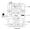
図1は、本発明の情報処理装置の一実施例を示す画像形成装置を含むシステムのブロックである。
図1において、1は本発明の情報処理装置としての画像形成装置である。
画像形成装置1は、スキャナ装置2、コントローラ3、プリンタ装置4、操作部5、ハードでディスク6、FAX装置7を有する。
スキャナ装置2は、原稿から光学的に画像を読み取りデジタル画像に変換する読取装置である。プリンタ装置4は、デジタル画像を紙デバイスに出力する出力装置である。操作部5は、画像形成装置1の操作を行うためのものである。ハードでディスク(HDD)6は、デジタル画像や制御プログラム等を記憶する。FAX装置7は、電話回線等を介してデジタル画像を送受信する。
Example 1 will be described with reference to FIGS. 1, 2, 3, 4, 5, and 6.
FIG. 1 is a block diagram of a system including an image forming apparatus showing an embodiment of an information processing apparatus of the present invention.
In FIG. 1, reference numeral 1 denotes an image forming apparatus as an information processing apparatus according to the present invention.
The image forming apparatus 1 includes a
The
コントローラ3は、スキャナ装置2、プリンタ装置4、操作部5、ハードでディスク6、FAX装置7等の各モジュールと接続され、各モジュールに指示を出すことで、画像形成装置1上でジョブを実行する制御装置である。
The
画像形成装置1は、LAN8経由でコンピュータ9からデジタル画像の入出力、ジョブの発行や機器の指示等も行うことが可能である。
スキャナ装置2は、自動的に原稿束を自動的に逐次入れ替えることが可能な原稿給紙ユニット(DFユニット)21、原稿を光学スキャンしデジタル画像に変換することが可能なスキャナユニット22を有し、変換された画像データはコントローラ3に送信される。
The image forming apparatus 1 can perform digital image input / output, job issuance, device instruction, and the like from the computer 9 via the
The
プリンタ装置4は、紙束から一枚ずつ逐次給紙可能な給紙ユニット42、給紙した紙に画像データを印刷するためのマーキングユニット41、印刷後の紙を排紙するための排紙ユニット43を有する。
The printer device 4 includes a
画像形成装置1は、多彩なジョブを実行可能である。一例を以下に記載する。
・複写機能;スキャナ装置2から読み込んだ画像をハードディスク装置6に記録し、同時にプリンタ装置4を使用して印刷を行う。
・画像送信機能;スキャナ装置2から読み込んだ画像をLAN8を介してコンピュータ9に送信する。
・画像保存機能;スキャナ装置2から読み込んだ画像をハードディスク装置6に記録し、必要に応じて画像送信や画像印刷を行う。
・画像印刷機能;コンピュータ9から送信された例えばページ記述言語を解析し、プリンタ装置4で印刷する。
The image forming apparatus 1 can execute various jobs. An example is described below.
Copy function: The image read from the
Image transmission function: An image read from the
Image storage function: The image read from the
Image printing function: Analyzes, for example, a page description language transmitted from the computer 9 and prints it by the printer device 4.
図2は、コントローラ3の構成の一例を示すブロック図である。本図を用いて本発明を具体的に適用するモジュールであるコントローラ3について述べる。
図2に示すように、コントローラ3は、メインボード200と、サブボード220を有する。
メインボード200は、いわゆる汎用的なCPUシステムである。メインボード200は、CPU201、ブートロム202、メモリ203、バスコントローラ204、不揮発性メモリ205、ディスクコントローラ206、フラッシュディスク(SSD等)207、USBコントローラ(USBインタフェース)208、ネットワークインタフェースカード(NIC)209等を有する。
FIG. 2 is a block diagram illustrating an example of the configuration of the
As shown in FIG. 2, the
The main board 200 is a so-called general-purpose CPU system. The main board 200 includes a
CPU201は、メインボード200全体を制御する。ブートロム202は、ブートプログラムを格納する。メモリ203は、CPU201がワークメモリとして使用するRAMである。バスコントローラ204は、外部バスとのブリッジ機能を有する。不揮発性メモリ205は、電源断された状態でもデータを記憶保持可能なメモリである。
The
ディスクコントローラ206は、HDD6等のストレージ装置を制御する。フラッシュディスク(SSD等)207は、半導体デバイスで構成された比較的小容量なストレージ装置である。USBコントローラ208は、USBメモリ210等のUSB機器を制御する。NIC209は、ネットワークとの通信を制御する。
The
メインボード200には外部に、USBメモリ210、操作部5、ハードディスク装置6等が接続される。
サブボード220は、比較的小さな汎用CPUシステムと、画像処理ハードウェアから構成される。サブボード220は、CPU221、メモリ223、バスコントローラ224、不揮発性メモリ225、画像処理プロセッサ226、デバイスコントローラ227、228を有する。
Externally connected to the main board 200 are a
The sub board 220 includes a relatively small general-purpose CPU system and image processing hardware. The sub board 220 includes a
CPU221は、サブボード220全体を制御する。メモリ223は、CPU221がワークメモリとして使用するRAMである。バスコントローラ224は、外部バスとのブリッジ機能を有する。不揮発性メモリ225は、電源断された状態でもデータを記憶保持可能なメモリである。画像処理プロセッサ226は、リアルタイムデジタル画像処理を行う。デバイスコントローラ228は、スキャナ装置2との接続を制御し、スキャナ装置2から入力されるデジタル画像データを画像処理プロセッサ226に受け渡す。デバイスコントローラ227は、プリンタ装置4との接続を制御し、画像処理プロセッサ226で画像処理されたデジタル画像データをプリンタ装置4に受け渡す。FAX装置7は、CPU221が直接制御を行う。
The
なお、本図はブロック図であり簡略化している。例えばCPU201、CPU221等にはチップセット、バスブリッジ、クロックジェネレータ等のCPU周辺ハードウェアが多数含まれているが、説明の粒度的に不必要であるため簡略化記載しており、このブロック構成が本発明を制限するものではない。なお、図2で省略した構成の一部を図3、図6等に示す。
This figure is a block diagram and is simplified. For example, the
以下、コントローラ3の動作について、紙デバイスによる画像複写を例に説明する。
利用者が操作部5から画像複写を指示すると、CPU201がCPU221を介してスキャナ装置2に画像読み取り命令を送る。スキャナ装置2は、紙原稿を光学スキャンしデジタル画像データに変換してデバイスコントローラ228を介して画像処理プロセッサ226に入力する。画像処理プロセッサは、CPU221を介してメモリ223にDMA転送を行いデジタル画像データの一時保存を行う。
Hereinafter, the operation of the
When the user instructs image copying from the
CPU201は、デジタル画像データがメモリ223に一定量もしくは全て入ったことが確認できると、CPU221を介してプリンタ装置4に画像出力指示を出す。CPU221は、画像処理プロセッサ226にメモリ223の画像データの位置を教える。画像処理プロセッサ226は、プリンタ装置4からの同期信号に従ってメモリ223上の画像データがデバイスコントローラ227を介してプリンタ装置4に送信し、プリンタ装置4にて紙デバイスにデジタル画像データが印刷される。
When the
なお、複数部印刷を行う場合、CPU201はメモリ223の画像データをハードディスク6に保存し、2部目以降はスキャナ装置2から画像データを入力しなくてもプリンタ装置4に画像データを送ることが可能である。
When printing multiple copies, the
図6は、コントローラ3の電源制御・リセット回路回りに注目したブロック図である。
図6において、601は、メインボード200上のリセット回路である。602は、メインボード200上のH/Wの基本的な部分を制御するBIOSである。603は電源監視H/Wで、本システムの電源制御を監視する専用H/Wロジック回路である。なお、電源監視H/W603は、ASIC等の場合、小さなCPUシステム等でもよい。
FIG. 6 is a block diagram focusing on the power supply control / reset circuit of the
In FIG. 6,
604は、サブボード220上のリセット回路である。605は、メインボード200上のハードウェア(H/W)である。606は、サブボード220上のハードウェア(H/W)群である。
メインボード200やサブボード220上に搭載されているH/Wのような同期型のH/Wでは、リセットにより内部状態をリセットするため、電源ON後電力が各チップに供給された後に、リセット回路が各H/Wをリセットする必要がある。また、複数のH/Wチップは主従関係を持つため、リセットシーケンスを設計し、順次リセットを掛けていくことになる。そのため一般的には本実施例のように一つのボードに一つのリセット回路を持ち、各々のボード内のリセット動作を各リセット回路が行うことになる。 In the synchronous type H / W such as H / W mounted on the main board 200 or the sub board 220, the internal state is reset by reset. Therefore, after power is turned on, power is supplied to each chip. The circuit needs to reset each H / W. Since a plurality of H / W chips have a master-slave relationship, a reset sequence is designed and reset is sequentially performed. Therefore, in general, one reset circuit is provided on one board as in this embodiment, and each reset circuit performs a reset operation in each board.
メインボード200のシステムは、特に本装置で主となるボードであり、各種機能を有する電源監視H/W603を備えている。例えば、電源監視H/W603は、省電力/電源スイッチ301(図3)からのスイッチの状態(307)を入力し、電源リモート線308を用いてメインボード200における電源供給を制御することができる。
The system of the main board 200 is a board mainly used in the present apparatus, and includes a power supply monitoring H /
CPU201が正常に動作出来る状態では、CPU201の指示に従いシステムにリセットを掛けることが可能である。一方、CPU201に電源が供給されていない状態では、電源監視H/W603が電源スイッチの入力(307)から電源リモート信号308を制御してコントローラ3に電源を投入することができる。
In a state where the
BIOS602は、低レベルのH/W制御ライブラリ等が含まれているものである。BIOS602は、一般的にはIBM互換機の互換性確保のためのものであり、いわゆるコンピュータシステム上必須ではないが、例えばACPI規格による省電力機能の一部を実行することも可能であるため実施例記載した。
The
本発明では待機状態として一般的なACPI−S3方式(メモリをレジュームする)を例に説明する。また、BIOS602はその機能の一部のためだけに記載したものである。
In the present invention, a general ACPI-S3 system (resumes a memory) will be described as an example of a standby state. The
以上のH/W構成を有する画像形成装置1において、例えば、ユーザが省電力/電源スイッチ301(図3)をOFFにすると、CPU201はライン307と電源監視H/W603を介して、前記電源スイッチの状態を受け取ることが可能である。つまり、通常、CPU201は電源OFFを検知してシャットダウンシーケンスを動作させ、電源監視H/W603にシャットダウン指示を行う。以下、シャットダウンシーケンスの一例を説明する。
In the image forming apparatus 1 having the above H / W configuration, for example, when the user turns off the power saving / power switch 301 (FIG. 3), the
なお、上記シャットダウンシーケンスでは、例えば、CPU201は、FAX装置7、USBコントローラ208、NIC209の通信処理を停止する。さらにCPU201は、メモリ203に格納されているデータのうち、FAX装置7の受信データや、操作部5からの設定データ等、電源オフ後もバックアップの必要なデータを不揮発性メモリ205に転送し格納する。さらに、CPU201は、HDD6等の電源オフ時の終了シーケンスが規定された補助記憶装置を使用する場合は、その補助記憶装置に対し規定の電源オフ制御を実行する。以上のようなシーケンスを終了すると、CPU201は、電源監視H/W603にシャットダウン指示を行う。
In the shutdown sequence, for example, the
このシャットダウン指示に応じて電源監視H/W603が、電源リモート信号308を介してAC−DCコンバータ303(図3)に電源OFFを通知し、コントローラ3のDC電源供給源である306(図3)をOFFにすることで、本システムは完全にシャットダウンされる。
In response to this shutdown instruction, the power monitoring H /
このシャットダウンでは、CPU201上のプログラムも完全に終了するため、次回省電力/電源スイッチ301をONにした際、CPU201のプログラムは通常通り起動することになる。
In this shutdown, the program on the
次に、本実施例におけるACPI−S3サスペンド方式の動作について説明する。
CPU201は、例えばOSの省電力I/Fをコールすることで、最終的に、BIOS602と電源監視H/W603の機能であるACPI−S3状態に遷移する。CPU201は、電源リモート信号308を介して電源ユニット302(図3)に指示し、ACPI−S3省電力状態へと遷移させることが可能である。この状態では、メモリ203と一部のH/Wのみが通電状態となる。
Next, the operation of the ACPI-S3 suspend system in this embodiment will be described.
For example, the
この時、システムとしては、電源OFFの状態ではなくメモリ203にプログラム状態を保持した「一時中断状態」となっており、所定の外部要因によりサスペンド状態が解除されると短時間でプログラムの実行を再開できる。
At this time, the system is in a “temporary suspension state” in which the program state is held in the
本実施例の画像形成装置1は、ユーザが省電力/電源スイッチ301をONにしてから実際にコピー等の動作が可能になるまでの待ち時間を短縮するため、省電力/電源スイッチ301のOFF時に、上述のACPI−S3サスペンド方式の動作によりメモリ等の一部分を通電状態としたまま待機する機能を備えている。
In the image forming apparatus 1 according to the present exemplary embodiment, the power saving /
なお、この状態(後述する図3(C)の状態)は、省電力状態(後述する図3(B)の状態)とは異なり、NIC209、FAX7は非通電となっている。説明上の区別のため、この機能により待機している状態(図3(C))を「クイックOFF状態」と呼び、通常の電源がOFFとなっている状態を「電源OFF状態」と呼ぶことにする。
In this state (the state shown in FIG. 3C described later) is different from the power saving state (the state shown in FIG. 3B described later), the
本実施例の画像形成装置1のユースケースとして、例えば、普段は待ち時間を短縮するために画像形成装置1をクイックOFF状態としているが、特定の場合のみ電源OFF状態としたい、というケースも有りうる。クイックOFF状態では、僅かではあるが電力を消費するため、夜間、休日、長期休暇の間は電源OFF状態としたい、という場面などである。このため、本発明の画像形成装置1は、省電力/電源スイッチ301(図3)のOFF後に「クイックOFF状態」と「電源OFF状態」のどちらの状態へ遷移するかを、例えば操作部5の所定のボタンを予め操作しておくことなどにより、ユーザが選択設定できるように構成する。この設定は、不揮発性メモリ205に保持されるものとする。
As a use case of the image forming apparatus 1 of the present embodiment, for example, there is a case where the image forming apparatus 1 is usually in a quick OFF state in order to shorten the waiting time, but only in a specific case, it is desired to set the power OFF state. sell. In the quick-off state, a small amount of power is consumed, and there is a situation where it is desired to turn off the power during nighttime, holidays, and long vacations. For this reason, the image forming apparatus 1 according to the present invention determines, for example, the
なお、本実施例の画像形成装置1では、省電力/電源スイッチ301をOFFした際の、画像形成装置1の内部状態に依存して、「クイックOFF状態」と「電源OFF状態」のどちらの状態へ遷移するかが決定される場合もある。
In the image forming apparatus 1 according to the present exemplary embodiment, depending on the internal state of the image forming apparatus 1 when the power saving /
以下、図3を参照して、画像形成装置1における電源と電源スイッチの構成及び電源供給状態について説明する。
図3は、画像形成装置1における電源と電源スイッチの構成及び電源供給状態を示す図である。
図3(A)は画像形成装置1における電源と電源スイッチの構成を示す。
図3(A)において、301はトグル型の省電力/電源スイッチであり、ON/OFFの状態のどちらか一方の状態をメカ的に保持し続けるスイッチである。操作者は、省電力/電源スイッチ301をON/OFFのいずれか側に倒すことで状態を入力する。
Hereinafter, the configuration of the power source and the power switch and the power supply state in the image forming apparatus 1 will be described with reference to FIG.
FIG. 3 is a diagram illustrating the configuration of the power source and the power switch and the power supply state in the image forming apparatus 1.
FIG. 3A shows a configuration of a power source and a power switch in the image forming apparatus 1.
In FIG. 3A,
302は電源ユニットである。303はAC−DCコンバータである。304はAC電源入力部である。306は、コントローラ3に対してDC電源を供給する電源ケーブルである。300は、プリンタ装置4に対して電源を供給するDC電源ケーブルである。312は、スキャナ装置2に対してDC電源を供給する電源ケーブルである。
307は、トグル型の省電力/電源スイッチ301の状態をコントローラに通知するラインである。308は、AC−DCコンバータ303の出力を制御することの可能な電源リモート信号である。
A
操作者は省電力/電源スイッチ301を操作することで、画像形成装置1をON/OFF等することが可能である。この省電力/電源スイッチ301は、ON時にAC−DCコンバータ303に接続されており、電源の通電状態を制御することができる。
The operator can turn on / off the image forming apparatus 1 by operating the power saving /
画像形成装置1の通電状態(電力状態)には、「電源OFF状態」、第1電力状態として「電源ON状態(アクティブ状態)」、第2電力状態として「省電力状態」、第3電力状態として「クイックOFF状態」等がある。以下、個別に説明する。 The energization state (power state) of the image forming apparatus 1 includes “power OFF state”, “power ON state (active state)” as the first power state, “power saving state”, and third power state as the second power state. As “quick OFF state”. Hereinafter, it demonstrates individually.
「電源ON状態(アクティブ状態)」の場合、図3の全ての箇所に電源が供給される。
「電源OFF状態」に移行する場合、コントローラ3によるシステムのシャットダウンが完了するまで、電源ケーブル306によるコントローラ3への電源供給が停止されないように構成されている。省電力/電源スイッチ301がOFFになったことがライン307を介してコントローラ3に通知されると、コントローラ3はシャットダウンを実行し、シャットダウンが完了した後に、電源リモート信号308を用いて電源ケーブル306によるコントローラ3へのDC電源供給をOFFにする。なお、電源ケーブル300、312によるプリンタ装置4、スキャナ装置2への電源供給は、省電力/電源スイッチ301のOFF時に停止されるように構成されている。このようにして、図3の全ての箇所への電源供給が停止する。
In the “power ON state (active state)”, power is supplied to all the locations in FIG.
When shifting to the “power OFF state”, the power supply to the
「省電力状態」に移行する場合は、プリンタ装置4、スキャナ装置2のDC電源供給はOFFとなり、コントローラ3への電源供給は図3(B)の通りとなる。なお、図3(B)は、AC−DCコンバータ303の一部と、コントローラ3を詳細に示したものである。
When shifting to the “power saving state”, the DC power supply of the printer device 4 and the
図3(B)に示すFET(Field effect transistor)330、FET340は、AC−DCコンバータ303に含まれるものである。CPU201、メモリ203、CPLD(Complex Programmable Logic Device)320、NIC209は、コントローラ3に含まれるものである。なお、FAX装置7の受信が、省電力状態からの復帰要因であるため、図3(B)では、便宜上、コントローラ3にFAX装置7が含まるように記載している。また、CPLD320は、電源監視H/W603(図6)内に含まれるものである。
An FET (Field effect transistor) 330 and an
「省電力状態」の場合では、CPLD320からAC−DCコンバータ303に通知されるリモート信号(3082)により、FET340のみがOFFとなり、これに接続される、省電力状態の場合に通電不要なCPU201への電源供給(3063)がOFFとなる(図3(B)点線部分)。一方、省電力状態の場合に通電が必要なメモリ203、CPLD320、NIC209、FAX7への電源供給(3061,3062)はONのままである(図3(B)実線部分)。
In the “power saving state”, only the
また、「クイックOFF状態」に移行する場合も、プリンタ装置4、スキャナ装置2のDC電源供給(3062)はOFFとなり、コントローラ3への電源供給は図3(C)の通りとなる。
In addition, when shifting to the “quick OFF state”, the DC power supply (3062) of the printer device 4 and the
「クイックOFF状態」の場合は、CPLD320から通知されるリモート信号(3081,3082)よりFET330およびFET340がOFFとなり、これらに接続されるクイックOFF状態の場合に通電不要なNIC209、CPU201、FAX7への電源供給(3062,3063)がOFFとなる(図3(C)点線部分)。一方、クイックOFF状態の場合に通電が必要なメモリ203、CPLD320への電源供給(3061)はONのままである。
In the “quick OFF state”, the
このように、「クイックOFF状態」の場合は、省電力状態より更に多くのハードウェアモジュールへの電源供給を停止することで、省電力状態よりも一層の低消費電力状態を実現することができる。ただし、「クイックOFF状態」の場合は、NIC209、FAX7が利用できないため、FAX受信や、リモートホストからのジョブの受信が不可となる。
As described above, in the “quick OFF state”, it is possible to realize a lower power consumption state than the power saving state by stopping the power supply to more hardware modules than the power saving state. . However, in the “quick OFF state”, the
本実施例では、OFF/ONが明示的なトグル型スイッチを用いているが、パーソナルコンピュータ等では状態を持たない電源スイッチ(電源スイッチ自体が省電力移行スイッチとして機能するもの等も含む)を採用しているものが多数ある。これらの状態を持たないスイッチは、(1)装置電源が入っている状態では「OFF/省電力状態移行指示」として機能し、(2)装置電源が入っていない状態においては「ON」と機能する。また、(3)一定時間以上スイッチを押下し続けることで「強制OFF」を入力する、等の制御パターンがある。 In this embodiment, a toggle switch with an explicit OFF / ON is used, but a power switch that does not have a state in a personal computer or the like (including a power switch that functions as a power saving transition switch) is adopted. There are a lot of things. A switch that does not have these states functions as (1) “OFF / power saving state transition instruction” when the device power is on, and (2) “ON” when the device power is off. To do. Further, there is a control pattern such as (3) “forced OFF” is input by continuously pressing the switch for a certain time.
本発明の情報処理装置は、スイッチをトグル型スイッチに限定するものではなく、状態を持たないスイッチを本発明の情報処理装置に用いる場合、上述の(1)、(2)のON/OFFのパターンにトグルスイッチのON/OFFを当てはめればよい。 The information processing apparatus of the present invention is not limited to a toggle type switch. When a switch having no state is used for the information processing apparatus of the present invention, the ON / OFF of the above (1) and (2) What is necessary is just to apply ON / OFF of a toggle switch to a pattern.
以下、図4のフローチャートを参照して、実施例1において一定時間利用されない状況が続いた場合の画像形成装置1の動作について説明する。
図4は、実施例1において一定時間利用されない状況が続いた場合の画像形成装置1の動作を示すフローチャートである。本フローチャートの処理は、画像形成装置1のコントローラ3がプログラム等に従って動作することによって実現される。例えば、HDD6もしくはフラッシュディスク207に格納されたプログラムに従ってCPU201が動作、また、内部のプログラミング素子に書き込まれたプログラムに従ってCPLD320が動作することによって実現される。なお、CPU201が動作している状態では、CPU201がプログラムに従って実行し、CPU201が停止している状態では、CPLD320が実行するものとする。
Hereinafter, with reference to the flowchart of FIG. 4, the operation of the image forming apparatus 1 when the situation in which the first embodiment is not used for a certain period of time continues will be described.
FIG. 4 is a flowchart illustrating the operation of the image forming apparatus 1 when a situation where the apparatus is not used for a certain period of time continues in the first exemplary embodiment. The processing of this flowchart is realized by the
電源の入っていない画像形成装置1に対して、省電力/電源スイッチ301が押されると(S400)、電源ユニット302から画像形成装置1の各部に電力が供給され、画像形成装置1が起動して利用可能な状態「電源ON状態(アクティブ状態)」となる(S410)。
When the power saving /
その後、CPU201は、一定時間操作がなされない等の所定の条件を満たしたと判定すると、画像形成装置1を「省電力状態」に移行させる(第1移行処理)(S412)。なお、省電力状態に移行した状態では、図3(B)に示したように、CPU201への電力供給は停止されるが、メモリ203、CPLD320、FAX装置7、NIC209等への電力供給は継続される。
Thereafter, when the
省電力状態では、CPLD320は、省電力/電源スイッチ301の状態を監視する(S420)。なお、省電力/電源スイッチ301が押されると、省電力/電源スイッチ301がOFFになったことが、スイッチ入力307によりCPLD320に通知される。
In the power saving state, the CPLD 320 monitors the state of the power saving / power switch 301 (S420). When the power saving /
CPLD320は、省電力/電源スイッチ301が押されたと判定した場合(S420でYes)、電源リモート信号308を用いて電源ケーブル306によるコントローラ3へのDC電源供給をOFFにする(S430)。これにより、画像形成装置1が電源OFF状態となり、本フローチャートが終了する。
When the CPLD 320 determines that the power saving /
一方、省電力/電源スイッチ301が押されない場合(S420でNo)、CPLD320は、画像形成装置1が利用可能となってから操作がないまま一定時間が経過したかどうかを判定する(S440)。なお、ここで「操作」とは、操作部5からの操作に限定されるものではなく、例えばネットワーク8やFAX装置7を介してジョブが入力された場合にも操作があったと判断する。即ち、画像形成装置1に外部から何らかの指示が入力された場合、S440で操作があったと判断するものとする。
On the other hand, when the power saving /
そして、まだ一定時間が経過していないと判定した場合(S440でNo)、CPLD320は、S420に処理を戻す。なお、図示しないが、一定時間が経過する前に操作があった場合は、CPLD320は、電源リモート信号(図3(B)の3082)をAC−DCコンバータ303内のFET340に送信する。これにより、電源オフされていた画像形成装置1の各部への電力供給が再開され、画像形成装置1は、スタンバイモードに復帰し、利用可能な状態となる。
If it is determined that the predetermined time has not yet elapsed (No in S440), the CPLD 320 returns the process to S420. Although not shown, when an operation is performed before a certain period of time elapses, the CPLD 320 transmits a power supply remote signal (3082 in FIG. 3B) to the
一方、画像形成装置1が利用可能となってから操作がないまま一定時間が経過したと判定した場合(S440でYes)、CPLD320は、S450に処理を進める。
S450では、CPLD320は、FAX装置7やNIC209を利用した送信予約が存在するかどうかを判定する。なお、送信予約の情報は、メモリ203や不揮発性メモリ205に記憶されているものとする。また、ここでは、FAX装置7やNIC209を利用した送信予約としたが、受信予約を含めた通信予約でもよく、また、外部との通信予約に限定されるものではなくジョブの実行予約であれば他のジョブの実行予約を含めて判断してもよい。
On the other hand, when it is determined that a certain time has passed without any operation since the image forming apparatus 1 becomes available (Yes in S440), the CPLD 320 advances the process to S450.
In S450, the CPLD 320 determines whether there is a transmission reservation using the
そして、送信予約があると判定した場合(S450でYes)、CPLD320は、S480に処理を進める。
S480では、CPLD320は、予約されている送信時間まで待機し、予約されている送信時間になると、S490に処理を進める。
S490では、CPLD320は、電源リモート信号(図3(B)の3082)によりAC−DCコンバータ303内のFET340をオンにして、画像形成装置1を「電源ON状態(アクティブ状態)」に復帰させる。さらに、CPU201が、上記予約されている送信処理を実行し、該送信処理を完了すると、画像形成装置1を「省電力状態」に移行させる。「省電力状態」に移行すると、CPLD320は、S440に処理を移行させる。
If it is determined that there is a transmission reservation (Yes in S450), the CPLD 320 advances the process to S480.
In S480, the CPLD 320 waits until the reserved transmission time, and proceeds to S490 when the reserved transmission time is reached.
In S490, the CPLD 320 turns on the
一方、送信予約が無いと判定した場合(S450でNo)、CPLD320は、S460に処理を進める。
S460では、CPLD320は、画像形成装置1を、「クイックOFF状態」に移行させるように制御する(第2移行処理)。即ち、CPLD320は、電源リモート信号(図3(B)の3081)によりAC−DCコンバータ303内のFET340をオフにする。なお、ここで、省電力/電源スイッチ310がOFF/ONが明示的なトグル型スイッチである場合は、CPLD320は、省電力/電源スイッチ301内の駆動部(不図示のソレノイド等)を駆動して省電力/電源スイッチ301をOFFにする。即ち、省電力/電源スイッチ310がオフ状態、オン状態を明示的に保持可能なスイッチである場合には、省電力/電源スイッチ310をオフ状態に変更させる。
なお、クイックOFF状態に移行すると、図3(C)に示したように、FAX7、NIC209への電力供給も停止されることとなる。
On the other hand, when it is determined that there is no transmission reservation (No in S450), the CPLD 320 advances the process to S460.
In S460, the CPLD 320 controls the image forming apparatus 1 to shift to the “quick OFF state” (second shift process). That is, the CPLD 320 turns off the
In addition, when it transfers to a quick OFF state, as shown in FIG.3 (C), the electric power supply to FAX7 and NIC209 will also be stopped.
次に、CPLD320は、省電力/電源スイッチ301の状態を監視する(S470)。CPLD320は、省電力/電源スイッチ301が押されたことをライン307からの入力により検知すると(S470でYes)、電源リモート信号308をAC−DCコンバータ303に送信する。これにより、画像形成装置1の各部へ電力が供給され、画像形成装置1はスタンバイモードに復帰し、利用可能な状態に遷移する(S410)。なお、「クイックOFF状態」では、メモリ203にプログラム状態が保持されているため、短時間でプログラムの実行を再開できる。このため、画像形成装置1は、電源OFF状態から起動するのに比べて、短時間でスタンバイモードに復帰可能となる。
Next, the CPLD 320 monitors the state of the power saving / power switch 301 (S470). When the CPLD 320 detects that the power saving /
なお、図4のフローチャートでは、省電力状態において省電力/電源スイッチ301のOFFにされた場合(S420でYes)電源OFFにする(S430)の例を説明した。しかし、予め操作部5から、省電力状態での省電力/電源スイッチ301のOFF後の遷移が「クイックOFF状態」と設定されている場合(不揮発性メモリ205に格納されている)、CPLD320は、画像形成装置1を「クイックOFF状態」に遷移させるように制御するものとする。この場合、CPLD320は、S470に処理を進め、再度、省電力/電源スイッチ301の状態を監視するものとする。即ち、CPLD320は、省電力状態において、省電力/電源スイッチ301がオフにされた場合、電源オフ状態、又はクイックオフ状態に移行するように制御する(第3移行処理)。
In the flowchart of FIG. 4, the example in which the power is turned off (S430) when the power saving /
また、画像形成装置1が利用可能となってから操作がないまま一定時間が経過したと判定した場合(S440でYes)、CPLD320は、そのままS460において、画像形成装置1を「クイックOFF状態」に移行させるようにしてもよい。 If it is determined that a certain time has passed without any operation since the image forming apparatus 1 is available (Yes in S440), the CPLD 320 directly sets the image forming apparatus 1 to the “quick OFF state” in S460. You may make it transfer.
また、上記フローチャートでは、省電力状態で一定時間の間操作が無かった場合はクイックOFF状態に移行する構成を示した。しかし、スタンバイ状態で一定時間の間操作が無かった場合にすぐにクイックOFF状態に移行するように構成してもよい。 Further, the above-described flowchart shows a configuration in which the operation shifts to the quick OFF state when there is no operation for a certain time in the power saving state. However, it may be configured to immediately shift to the quick OFF state when there is no operation for a certain time in the standby state.
以上示したフローチャートに示したように、省電力状態(又はスタンバイ状態)で一定時間の間操作が無かった場合はクイックOFF状態に移行することで、省電力状態より電力消費の少ない状態に移行することができる。なおかつ、送信予約(所定のジョブの実行予約)がある際は、一定時間の間操作が無くてもクイックOFF状態に移行しないことで、送信予約を確実に処理することができる。 As shown in the flowchart shown above, when there is no operation for a certain period of time in the power saving state (or standby state), the state is shifted to the state of lower power consumption than the power saving state by shifting to the quick OFF state. be able to. In addition, when there is a transmission reservation (execution reservation for a predetermined job), the transmission reservation can be reliably processed by not shifting to the quick OFF state even if there is no operation for a certain period of time.
図5は、画像形成装置1にて操作無しに一定時間が経過して省電力/電源スイッチ301をOFF/ONした際の従来と本発明の電力状態を比較した図である。縦軸は電力状態を示し、横軸は経過時間を示している。また、省電力/電源スイッチ301をONにした以降の横軸上の「R」は、これ以降の時点で画像形成装置を利用できる状態であることを示している。
FIG. 5 is a diagram comparing the power state of the present invention and that of the present invention when the power saving /
図5(A)は従来の画像形成装置における電力状態を示す。すなわち、操作無しに一定時間が経過した際にシャットダウンを行って電源OFF状態とする場合に対応する。この場合は、電源OFF状態となった後、省電力/電源スイッチ301をONにしても、起動処理に時間がかかり、直ちには画像形成装置が利用できる状態にはならない。
FIG. 5A shows a power state in a conventional image forming apparatus. That is, it corresponds to a case where the power is turned off by performing a shutdown when a certain time has elapsed without any operation. In this case, even if the power saving /
図5(B)は本発明の画像形成装置における電力状態を示す。すなわち、操作無しに一定時間が経過した際にクイックOFF状態へ移行する場合に対応する。この場合は、クイックOFF状態への移行が行われた後、省電力/電源スイッチ301をONにすることで直ちに画像形成装置が利用できる状態になる(上述した電源オフ状態からの起動と比較して高速に起動できる)。 FIG. 5B shows a power state in the image forming apparatus of the present invention. In other words, this corresponds to a case where a transition to the quick OFF state occurs when a certain time has elapsed without any operation. In this case, after the transition to the quick OFF state, the image forming apparatus can be used immediately by turning on the power saving / power switch 301 (compared to the above-described startup from the power off state). And can be started quickly).
このように、本発明では、操作無し後一定時間が経過した際に、省電力状態より電力消費の低い状態(クイックオフ状態)を維持しつつ、省電力/電源スイッチ301の操作に応じて高速に通常状態に復帰が出来るようになる。
As described above, according to the present invention, when a certain period of time elapses after no operation is performed, a state in which the power consumption is lower than the power saving state (quick-off state) is maintained, and the power saving /
したがって、画像形成装置が利用されない時間が一定時間経過した時点で、その後の利用見込みに応じて、省電力状態より更に電力消費量が低い、より適した待機状態「クイックオフ状態」に移行して、極めて低消費電力で且つ高速起動可能に待機することができるようになる。 Therefore, when a certain period of time when the image forming apparatus is not used has passed, a transition to a more suitable standby state “quick-off state” in which the power consumption is lower than the power saving state is made in accordance with the prospect of subsequent use. Therefore, it is possible to stand by with extremely low power consumption and enabling high-speed activation.
即ち、省電力状態に加え、更に電力消費を抑えつつも高速に通常状態に復帰可能な「クイックOFF状態」に移行することが可能な画像形成装置を提供することができる。 In other words, in addition to the power saving state, it is possible to provide an image forming apparatus capable of shifting to the “quick OFF state” that can return to the normal state at high speed while further reducing power consumption.
実施形態2については、図1、図2、図3、図5、図6、図7を用いて説明する。
実施例1では、FAX等の送信予約がない場合は利用見込みがないと判断してクイックオフ状態に移行する構成を説明したが、実施例2では、外部接続用インタフェースに外部機器の接続がない場合は利用見込みがないと判断してクイックオフ状態に移行する構成とする。
The second embodiment will be described with reference to FIGS. 1, 2, 3, 5, 6, and 7.
In the first embodiment, a configuration has been described in which when there is no transmission reservation such as FAX, it is determined that there is no prospect of use and a transition is made to the quick-off state. However, in the second embodiment, there is no connection of an external device to the external connection interface. In such a case, it is determined that there is no possibility of use and a transition to the quick-off state is made.
実施例2は、特に、画像形成装置を外部ホストと外部接続用インタフェースにより接続して使用する場合に有効な実施例である。例えば一人のユーザが利用しているパーソナルコンピュータなどの情報機器と、USB等の外部接続用インタフェースにより画像形成装置とが接続されている場合に有効である。 The second embodiment is particularly effective when the image forming apparatus is used by being connected to an external host through an external connection interface. For example, this is effective when an information device such as a personal computer used by one user is connected to an image forming apparatus via an external connection interface such as a USB.
ここでは、外部接続用インタフェースの一例としてUSBを用いて説明するが、他の外部接続用インタフェースであってもよい。例えば、IEEE 1394や、Thunderbolt、SDカード等の規格に準じた外部接続用インタフェース(IEEE 1394インタフェース、Thunderboltインタフェース)であってもよい。即ち、USBインタフェースと同様に、ホストコンピュータ等からバスパワーの供給が可能なインタフェースであれば他のインタフェースであってもよい。 Here, the USB is used as an example of the external connection interface, but other external connection interfaces may be used. For example, it may be an external connection interface (IEEE 1394 interface, Thunderbolt interface) conforming to standards such as IEEE 1394, Thunderbolt, and SD card. That is, as with the USB interface, another interface may be used as long as it can supply bus power from a host computer or the like.
実施例2では、操作無し後一定時間が経過した際に、USBが通電状態であればユーザが画像形成装置をこれから利用し得ると判断してクイックOFF状態に移行する。一方、非通電状態であればユーザが画像形成装置を当分利用しないと判断してシャットダウンを行い、電源OFF状態とする。この動作を図7にて詳述する。その他については、実施形態1と全く同様である。 In the second embodiment, when a certain time has elapsed after no operation, if the USB is in an energized state, it is determined that the user can use the image forming apparatus from now on, and the quick OFF state is entered. On the other hand, if it is in a non-energized state, it is determined that the user will not use the image forming apparatus for the time being, a shutdown is performed, and the power is turned off. This operation will be described in detail with reference to FIG. Others are exactly the same as in the first embodiment.
図1、図2、図3、図5、図6については、全て実施形態1と同様である。なお、実施例2では、省電力状態ではUSBコントローラ208に対してAC−DCコンバータ303から電力供給されるものとし、クイックオフ状態ではUSBコントローラ208に対してAC−DCコンバータ303から電力供給が停止されるものとする。
1, 2, 3, 5, and 6 are all the same as those in the first embodiment. In the second embodiment, power is supplied from the AC-
以下、図7のフローチャートを参照して、実施例2において一定時間利用されない状況が続いた場合の画像形成装置1の動作について説明する。
図7は、実施例2において一定時間利用されない状況が続いた場合の画像形成装置1の動作を示すフローチャートである。本フローチャートの処理は、画像形成装置1のコントローラ3がプログラム等に従って動作することによって実現される。例えば、HDD6もしくはフラッシュディスク207に格納されたプログラムに従ってCPU201が動作、また、内部のプログラミング素子に書き込まれたプログラムに従ってCPLD320が動作することによって実現される。なお、CPU201が動作している状態では、CPU201がプログラムに従って実行し、CPU201が停止している状態では、CPLD320が実行するものとする。
Hereinafter, the operation of the image forming apparatus 1 when the situation in which the apparatus is not used for a certain period of time in
FIG. 7 is a flowchart illustrating the operation of the image forming apparatus 1 when a situation where the apparatus is not used for a certain period of time continues in the second embodiment. The processing of this flowchart is realized by the
なお、図4と同一のステップについては説明を省略し、図4と異なるステップのみ説明する。
S700〜S740の処理は、図4のS400〜S440と同一の処理のため説明は省略する。
S750では、CPLD320は、USBが通電状態である(USBコントローラ208に接続されたUSB機器から該USBコントローラ208に電力(USBバスパワー(USB bus power))が供給されている)かどうかを判定する。
Note that description of the same steps as those in FIG. 4 is omitted, and only steps different from those in FIG. 4 will be described.
The processing of S700 to S740 is the same as S400 to S440 of FIG.
In S750, the CPLD 320 determines whether the USB is in an energized state (power is supplied from the USB device connected to the
そして、USBが通電状態でない(USBバスパワーが供給されていない)と判定した場合(S750でNo)、CPLD320は、電源リモート信号308を用いて電源ケーブル306によるコントローラ3へのDC電源供給をOFFにする(S730)。これにより、画像形成装置1が電源OFF状態となり、本フローチャートが終了する。
If it is determined that the USB is not energized (USB bus power is not supplied) (No in S750), the CPLD 320 turns off the DC power supply to the
一方、USBが通電状態である(USBバスパワーが供給されている)と判定した場合(S750でYes)、CPLD320は、S760の処理を進める。
S760では、CPLD320は、画像形成装置1を、「クイックOFF状態」に移行させるように制御する。即ち、CPLD320は、電源リモート信号(図3(B)の3081)によりAC−DCコンバータ303内のFET340をオフにする。なお、ここで、省電力/電源スイッチ310がOFF/ONが明示的なトグル型スイッチである場合は、CPLD320は、省電力/電源スイッチ301内の駆動部(不図示のソレノイド等)を駆動して省電力/電源スイッチ301をOFFにする。
On the other hand, when it is determined that the USB is in an energized state (USB bus power is supplied) (Yes in S750), the CPLD 320 advances the process of S760.
In S760, the CPLD 320 controls the image forming apparatus 1 to shift to the “quick OFF state”. That is, the CPLD 320 turns off the
なお、クイックOFF状態に移行すると、図3(C)に示したように、FAX7、NIC209への電力供給も停止されることとなる。
S770の処理は、図4のS470と同一の処理のため説明は省略する。
In addition, when it transfers to a quick OFF state, as shown in FIG.3 (C), the electric power supply to FAX7 and NIC209 will also be stopped.
The process of S770 is the same as S470 of FIG.
以上示したフローチャートに示したように、省電力状態(又はスタンバイ状態)で一定時間の間操作が無かった場合、外部接続用インタフェースであるUSBが通電状態であればUSBコントローラ208介してパーソナルコントローラ(PC)等の外部ホストが接続されておりユーザがこれから外部ホストを用いて画像形成装置を利用し得ると判断し、画像形成装置をクイックOFF状態に移行する。これにより、省電力状態より電力消費の低い状態を維持しつつ、ユーザが画像形成装置を利用する際に、高速に通常状態に復帰できるようになる。一方、USBが非通電状態であればUSBコントローラ208を介して外部ホストが接続されておらずユーザが画像形成装置を既に利用していないと判断しシャットダウンを行い、電源OFF状態に移行する。
As shown in the flowchart shown above, when there is no operation for a certain time in the power saving state (or standby state), if the USB as the external connection interface is in the energized state, the personal controller ( PC) or the like is connected, and it is determined that the user can use the image forming apparatus using the external host, and the image forming apparatus is shifted to the quick OFF state. As a result, when the user uses the image forming apparatus while maintaining a state of lower power consumption than the power saving state, the user can return to the normal state at high speed. On the other hand, if the USB is in a non-energized state, it is determined that the external host is not connected via the
このように、本発明では、操作無し後一定時間が経過した際に、省電力状態より電力消費の低い状態(クイックオフ状態)を維持しつつ、省電力/電源スイッチ301の操作に応じて高速に通常状態に復帰が出来るようになる。
As described above, according to the present invention, when a certain period of time elapses after no operation is performed, a state in which the power consumption is lower than the power saving state (quick-off state) is maintained, and the power saving /
したがって、画像形成装置が利用されない時間が一定時間経過した時点で、その後の利用見込みに応じて、省電力状態より更に電力消費量が低い、より適した待機状態「クイックオフ状態」に移行して、極めて低消費電力で且つ高速起動可能に待機することができるようになる。 Therefore, when a certain period of time when the image forming apparatus is not used has passed, a transition to a more suitable standby state “quick-off state” in which the power consumption is lower than the power saving state is made in accordance with the prospect of subsequent use. Therefore, it is possible to stand by with extremely low power consumption and enabling high-speed activation.
なお、実施例2では、省電力状態において、USBコントローラ208にAC−DCコンバータ303からの電力が供給されるものとする。
実施例2では、省電力状態ではUSBコントローラ208に対してAC−DCコンバータ303から電力供給されているものとしたが、省電力状態ではUSBコントローラ208に対してAC−DCコンバータ303から電力供給されているとしてもよい。この場合、省電力状態ではUSBコントローラ208は、外部ホストからのUSBバスパワーによる電力供給により動作するものとする。
In the second embodiment, it is assumed that the power from the AC-
In the second embodiment, power is supplied from the AC-
以上、本発明の情報処理装置の一例として画像形成装置を用いて説明したが、本発明の情報処理装置は、画像形成装置に限定されるものではなく、他の情報処理装置であってもよい。 The image forming apparatus has been described above as an example of the information processing apparatus of the present invention. However, the information processing apparatus of the present invention is not limited to the image forming apparatus, and may be another information processing apparatus. .
なお、上述した各種データの構成及びその内容はこれに限定されるものではなく、用途や目的に応じて、様々な構成や内容で構成されることは言うまでもない。
以上、一実施形態について示したが、本発明は、例えば、システム、装置、方法、プログラムもしくは記憶媒体等としての実施態様をとることが可能である。具体的には、複数の機器から構成されるシステムに適用しても良いし、また、一つの機器からなる装置に適用しても良い。
また、上記各実施例を組み合わせた構成も全て本発明に含まれるものである。
It should be noted that the configuration and contents of the various data described above are not limited to this, and it goes without saying that the various data and configurations are configured according to the application and purpose.
Although one embodiment has been described above, the present invention can take an embodiment as, for example, a system, apparatus, method, program, or storage medium. Specifically, the present invention may be applied to a system composed of a plurality of devices, or may be applied to an apparatus composed of a single device.
Moreover, all the structures which combined said each Example are also contained in this invention.
(他の実施例)
また、本発明は、以下の処理を実行することによっても実現される。即ち、上述した実施形態の機能を実現するソフトウェア(プログラム)を、ネットワーク又は各種記憶媒体を介してシステム或いは装置に供給し、そのシステム或いは装置のコンピュータ(またはCPUやMPU等)がプログラムを読み出して実行する処理である。
(Other examples)
The present invention can also be realized by executing the following processing. That is, software (program) that realizes the functions of the above-described embodiments is supplied to a system or apparatus via a network or various storage media, and a computer (or CPU, MPU, or the like) of the system or apparatus reads the program. It is a process to be executed.
また、本発明は、複数の機器から構成されるシステムに適用しても、1つの機器からなる装置に適用してもよい。
本発明は上記実施例に限定されるものではなく、本発明の趣旨に基づき種々の変形(各実施例の有機的な組合せを含む)が可能であり、それらを本発明の範囲から除外するものではない。即ち、上述した各実施例及びその変形例を組み合わせた構成も全て本発明に含まれるものである。
Further, the present invention may be applied to a system composed of a plurality of devices or an apparatus composed of a single device.
The present invention is not limited to the above embodiments, and various modifications (including organic combinations of the embodiments) are possible based on the spirit of the present invention, and these are excluded from the scope of the present invention. is not. That is, the present invention includes all the combinations of the above-described embodiments and modifications thereof.
1 画像形成装置
3 コントローラ
201 CPU
203 メモリ
208 USBコントローラ
209 NIC
603 電源監視H/W
320 CPLD
DESCRIPTION OF SYMBOLS 1
203
603 Power supply monitoring H / W
320 CPLD
Claims (19)
プログラムを記憶するメモリと、
前記メモリに記憶される前記プログラムを実行するプロセッサと、
外部装置からデータを受信するネットワークインターフェースと、
前記ネットワークインターフェース及び前記メモリには電力が供給されるが前記プロセッサには電力が供給されない第1電力状態で所定時間が経過したことに基づいて、前記画像形成装置を前記第1電力状態から、前記メモリには電力が供給されるが前記ネットワークインターフェース及び前記プロセッサには電力が供給されない第2電力状態であって前記メモリに前記第2電力状態に移行する前の前記画像形成装置の状態を示す情報が格納された前記第2電力状態に移行させる電力制御手段と、
を有することを特徴とする画像形成装置。 An image forming apparatus,
A memory for storing the program;
A processor for executing the program stored in the memory;
A network interface for receiving data from an external device;
Based on the elapse of a predetermined time in a first power state in which power is supplied to the network interface and the memory but power is not supplied to the processor, the image forming apparatus is moved from the first power state to the first power state. Information indicating a state of the image forming apparatus in a second power state in which power is supplied to the memory but power is not supplied to the network interface and the processor and before the memory is shifted to the second power state. Power control means for shifting to the second power state in which is stored ,
An image forming apparatus comprising:
前記電源スイッチを前記オン状態から前記オン状態に動かす駆動手段と、をさらに有し、
前記電力制御手段は、前記画像形成装置を前記第1電力状態から前記第2電力状態に移行させるときに、前記駆動手段を制御して、前記電源スイッチを前記オン状態から前記オフ状態に動かす、ことを特徴とする請求項1乃至5のいずれか1項に記載の画像形成装置。 A power switch that is turned on or off according to a user operation;
Drive means for moving the power switch from the on state to the on state ;
The power control unit controls the driving unit to move the power switch from the on state to the off state when the image forming apparatus is shifted from the first power state to the second power state. The image forming apparatus according to claim 1, wherein the image forming apparatus is an image forming apparatus.
前記電源スイッチが前記オン状態から前記オフ状態になったことに基づいて前記画像形成装置が移行するべき状態を設定する設定手段と、をさらに有し、
前記電力制御手段は、前記第1電力状態において前記スイッチが前記オン状態から前記オフ状態になった場合に、前記設定手段の設定に基づいて、前記画像形成装置を前記第2電力状態又は前記メモリ、前記プロセッサ及び前記ネットワークインターフェースへの電力供給が停止される電源オフ状態に移行させる、ことを特徴とする請求項1乃至5のいずれか1項に記載の画像形成装置。 A power switch that is turned on or off according to a user operation;
Setting means for setting a state to which the image forming apparatus should shift based on the power switch being changed from the on state to the off state;
Said power control means, wherein when said switch is turned to the OFF state from the ON state in the first power state, based on the setting of the setting means, the image forming apparatus before Symbol second power state or the The image forming apparatus according to claim 1, wherein the image forming apparatus shifts to a power-off state in which power supply to the memory, the processor, and the network interface is stopped .
前記第2電力状態で前記スイッチが前記オフ状態から前記オン状態になった場合に、前記プロセッサは、前記メモリに記憶された前記情報を使って、前記画像形成装置を前記第2電力状態に移行する前の状態に戻す、ことを特徴とする請求項1乃至11のいずれか1項に記載の画像形成装置。 A power switch that is turned on or off according to a user operation;
When the switch is changed from the OFF state to the ON state in the second power state, the processor uses the information stored in the memory to shift the image forming apparatus to the second power state . the image forming apparatus according to any one of claims 1 to 11 return to the previous state, it is characterized in that.
前記画像形成装置を、プログラムを記憶するメモリ及び外部装置からデータを受信するネットワークインターフェースには電力が供給されるが前記メモリに記憶されるプログラムを実行するプロセッサには電力が供給されない第1電力状態に移行する工程と、
前記第1電力状態で所定時間が経過したことに基づいて、前記画像形成装置を前記第1電力状態から、前記メモリには電力が供給されるが前記ネットワークインターフェース及び前記プロセッサには電力が供給されない第2電力状態に移行する工程と、
前記画像形成装置が前記第1電力状態から前記第2電力状態に移行する前に、前記メモリに前記第2電力状態に移行する前の前記画像形成装置の状態を示す情報を格納する工程と、
を有することを特徴とする画像形成装置の制御方法。 A power control method for an image forming apparatus, comprising:
A first power state in which the image forming apparatus is supplied with power to a memory that stores a program and a network interface that receives data from an external apparatus, but is not supplied to a processor that executes the program stored in the memory The process of transitioning to
And especially on the basis of a constant time Tokoro in the first power state has elapsed, the image forming apparatus from the first power state, supply power to, but electric power is supplied the network interface and the processor is in the memory Transitioning to a second power state that is not performed;
Storing information indicating a state of the image forming apparatus before transitioning to the second power state in the memory before the image forming apparatus transitions from the first power state to the second power state;
A control method for an image forming apparatus, comprising:
Priority Applications (4)
| Application Number | Priority Date | Filing Date | Title |
|---|---|---|---|
| JP2012022870A JP5975662B2 (en) | 2012-02-06 | 2012-02-06 | Image forming apparatus and image forming apparatus control method |
| EP13152133.8A EP2624056B1 (en) | 2012-02-06 | 2013-01-22 | Image forming apparatus, control method for image forming apparatus, and storage medium |
| US13/758,736 US9600219B2 (en) | 2012-02-06 | 2013-02-04 | Image forming apparatus, power supply control method for image forming apparatus, and storage medium |
| CN201310047049.8A CN103248783B (en) | 2012-02-06 | 2013-02-06 | The control method of printing device, message processing device and printing device |
Applications Claiming Priority (1)
| Application Number | Priority Date | Filing Date | Title |
|---|---|---|---|
| JP2012022870A JP5975662B2 (en) | 2012-02-06 | 2012-02-06 | Image forming apparatus and image forming apparatus control method |
Publications (3)
| Publication Number | Publication Date |
|---|---|
| JP2013159030A JP2013159030A (en) | 2013-08-19 |
| JP2013159030A5 JP2013159030A5 (en) | 2015-03-26 |
| JP5975662B2 true JP5975662B2 (en) | 2016-08-23 |
Family
ID=47594569
Family Applications (1)
| Application Number | Title | Priority Date | Filing Date |
|---|---|---|---|
| JP2012022870A Active JP5975662B2 (en) | 2012-02-06 | 2012-02-06 | Image forming apparatus and image forming apparatus control method |
Country Status (4)
| Country | Link |
|---|---|
| US (1) | US9600219B2 (en) |
| EP (1) | EP2624056B1 (en) |
| JP (1) | JP5975662B2 (en) |
| CN (1) | CN103248783B (en) |
Families Citing this family (17)
| Publication number | Priority date | Publication date | Assignee | Title |
|---|---|---|---|---|
| JP6020353B2 (en) * | 2013-05-29 | 2016-11-02 | コニカミノルタ株式会社 | Information processing apparatus, image forming apparatus, remote operation method, remote control method, remote operation program, and remote control program |
| JP6184807B2 (en) * | 2013-09-03 | 2017-08-23 | シャープ株式会社 | Information processing apparatus and control program |
| JP6381325B2 (en) * | 2014-07-11 | 2018-08-29 | キヤノン株式会社 | Printing system comprising a printing device and a printing control device |
| JP2016030434A (en) * | 2014-07-30 | 2016-03-07 | 株式会社沖データ | Image forming apparatus |
| JP6609944B2 (en) * | 2015-03-13 | 2019-11-27 | セイコーエプソン株式会社 | Printing apparatus and printing apparatus control method |
| US9774753B2 (en) * | 2015-05-28 | 2017-09-26 | Canon Kabushiki Kaisha | Image forming apparatus, control method therefor, and storage medium |
| JP6430896B2 (en) * | 2015-06-05 | 2018-11-28 | アルパイン株式会社 | Standby processing control apparatus and standby processing control method for electronic device |
| JP6486214B2 (en) * | 2015-06-16 | 2019-03-20 | サトーホールディングス株式会社 | Printing apparatus and program |
| JP6390544B2 (en) * | 2015-07-31 | 2018-09-19 | 京セラドキュメントソリューションズ株式会社 | Image forming apparatus |
| JP2017185636A (en) * | 2016-04-01 | 2017-10-12 | セイコーエプソン株式会社 | Electronic apparatus and control method |
| JP6752078B2 (en) * | 2016-08-09 | 2020-09-09 | キヤノン株式会社 | Image forming device, its control method, and program |
| WO2018194676A1 (en) | 2017-04-21 | 2018-10-25 | Hewlett-Packard Development Company, L.P. | Multi sleep mode power saving |
| JP6703049B2 (en) * | 2018-07-25 | 2020-06-03 | キヤノン株式会社 | Information processing apparatus and method of controlling information processing apparatus |
| JP6669979B1 (en) * | 2018-12-28 | 2020-03-18 | 富士通クライアントコンピューティング株式会社 | Information processing system and relay device |
| JP7242351B2 (en) * | 2019-03-11 | 2023-03-20 | キヤノン株式会社 | Electronic devices that can omit software tampering detection processing at startup |
| JP7401227B2 (en) * | 2019-09-03 | 2023-12-19 | キヤノン株式会社 | Image forming apparatus, its control method, and program |
| JP7633599B2 (en) | 2021-06-25 | 2025-02-20 | サクサ株式会社 | Power supply control circuit |
Family Cites Families (67)
| Publication number | Priority date | Publication date | Assignee | Title |
|---|---|---|---|---|
| JPH10333506A (en) * | 1997-05-27 | 1998-12-18 | Ricoh Co Ltd | Image forming device |
| JPH11202690A (en) * | 1998-01-19 | 1999-07-30 | Ricoh Co Ltd | Image forming device |
| JP3839241B2 (en) * | 2000-03-30 | 2006-11-01 | 株式会社リコー | Image forming apparatus management system, image forming apparatus used therefor, and power supply control method therefor |
| KR100471056B1 (en) * | 2000-11-18 | 2005-03-07 | 삼성전자주식회사 | Computer system and Control method of Waiting mode for Computer system |
| JP2002359705A (en) * | 2001-06-01 | 2002-12-13 | Ricoh Co Ltd | Facsimile terminal |
| JP2003331674A (en) * | 2002-05-14 | 2003-11-21 | Konica Minolta Holdings Inc | Switch and image forming device |
| JP4172217B2 (en) * | 2002-07-19 | 2008-10-29 | 富士ゼロックス株式会社 | Power management device |
| KR100607949B1 (en) * | 2002-09-11 | 2006-08-03 | 삼성전자주식회사 | Multimedia data recording device, reproducing device and information storage medium using hierarchical information structure |
| JP4324084B2 (en) * | 2003-12-09 | 2009-09-02 | キヤノン株式会社 | Image processing apparatus and control method thereof |
| US7334146B2 (en) * | 2003-12-09 | 2008-02-19 | Canon Kabushiki Kaisha | Method for controlling an image processing apparatus based on a power supply status |
| CN100527725C (en) | 2004-03-05 | 2009-08-12 | 威盛电子股份有限公司 | How to adjust the power consumption of the network interface |
| US20060143454A1 (en) * | 2004-05-27 | 2006-06-29 | Silverbrook Research Pty Ltd | Storage of multiple keys in memory |
| KR100613608B1 (en) * | 2004-09-06 | 2006-08-21 | 삼성전자주식회사 | Device having a power saving mode function and a method for controlling the power saving mode |
| US7444096B2 (en) * | 2005-03-29 | 2008-10-28 | Hewlett-Packard Development Company, L.P. | Electronic device power supply |
| JP2007108862A (en) | 2005-10-11 | 2007-04-26 | Canon Inc | Sleep mode shift control method for network connecting peripheral equipment |
| JP2007295080A (en) | 2006-04-21 | 2007-11-08 | Ricoh Co Ltd | Communication equipment, communication method, program, and computer-readable recording medium |
| JP2007324956A (en) * | 2006-06-01 | 2007-12-13 | Canon Inc | Image processing apparatus and image processing method |
| JP2008204209A (en) * | 2007-02-21 | 2008-09-04 | Sony Corp | Electronic equipment, return interface setting method, return communication method and computer program |
| JP2008269609A (en) * | 2007-04-16 | 2008-11-06 | Toshiba Corp | Information processing apparatus, image processing apparatus, resume control method used in information processing apparatus, and resume control method used in image processing apparatus |
| US7877618B2 (en) * | 2007-08-29 | 2011-01-25 | Dell Products L.P. | Systems and methods for power management |
| JP2009132050A (en) * | 2007-11-30 | 2009-06-18 | Ricoh Co Ltd | Image forming apparatus and control method and program of image forming apparatus |
| JP2009177387A (en) * | 2008-01-23 | 2009-08-06 | Seiko Epson Corp | Multifunction machine and power saving method of the multifunction machine |
| JP5207792B2 (en) * | 2008-02-19 | 2013-06-12 | キヤノン株式会社 | Information processing apparatus and information processing method |
| JP4547436B2 (en) * | 2008-03-07 | 2010-09-22 | シャープ株式会社 | Image forming apparatus |
| JP2009225139A (en) * | 2008-03-17 | 2009-10-01 | Brother Ind Ltd | Image processing apparatus |
| JP4544345B2 (en) * | 2008-06-18 | 2010-09-15 | コニカミノルタビジネステクノロジーズ株式会社 | Image forming apparatus and method of controlling image forming apparatus |
| JP2010154692A (en) * | 2008-12-25 | 2010-07-08 | Nikon Corp | Charger for electronic device, electronic device, and charging method |
| US20100202018A1 (en) * | 2009-02-09 | 2010-08-12 | Kabushiki Kaisha Toshiba | Image forming apparatus, power-saving control method, and computer-readable recording medium having recorded therein power-saving control program |
| JP2010194884A (en) * | 2009-02-25 | 2010-09-09 | Fuji Xerox Co Ltd | Image forming apparatus and program |
| JP4720926B2 (en) * | 2009-03-26 | 2011-07-13 | ブラザー工業株式会社 | Processing equipment |
| US8446610B2 (en) * | 2009-04-07 | 2013-05-21 | Kabushiki Kaisha Toshiba | Image forming apparatus, power-saving control method, and computer-readable recording medium in which power-saving control program is recorded |
| US8132032B2 (en) * | 2009-04-10 | 2012-03-06 | MSI Computer (Shenzhen) Co. Ltd. | Electronic device for reducing power consumption during sleep mode of computer motherboard and motherboard thereof |
| CN101909380B (en) * | 2009-06-03 | 2013-10-09 | 富士迈半导体精密工业(上海)有限公司 | Street lamp system |
| JP5332923B2 (en) * | 2009-06-08 | 2013-11-06 | 株式会社リコー | Image forming apparatus |
| JP2011022559A (en) * | 2009-06-15 | 2011-02-03 | Ricoh Co Ltd | Image forming apparatus, return processing method, and program |
| JP5545466B2 (en) * | 2009-09-04 | 2014-07-09 | 富士ゼロックス株式会社 | Image forming system, image forming apparatus, and image forming program |
| US8339626B2 (en) * | 2009-09-08 | 2012-12-25 | Samsung Electronics Co., Ltd. | Image forming apparatus and controlling method thereof |
| PL2437180T3 (en) * | 2009-09-09 | 2014-05-30 | Hp Printing Korea Co Ltd | Image forming apparatus, system on chip unit and driving method thereof |
| KR101653619B1 (en) * | 2009-10-06 | 2016-09-02 | 삼성전자주식회사 | Image forming apparatus and method fot controlling power of thereof |
| US8127126B2 (en) * | 2009-10-06 | 2012-02-28 | Li-Chun Lai | Integrated power supply and network connection control device for cord set |
| JP5482075B2 (en) * | 2009-10-07 | 2014-04-23 | 株式会社リコー | Power supply control apparatus, image forming apparatus, power supply control method, and power supply control program |
| JP5586924B2 (en) * | 2009-11-24 | 2014-09-10 | キヤノン株式会社 | Image forming apparatus |
| JP2011133515A (en) * | 2009-12-22 | 2011-07-07 | Canon Inc | Voltage supply device |
| JP5446943B2 (en) * | 2010-01-29 | 2014-03-19 | ソニー株式会社 | Printing system and printer apparatus control method |
| JP5286316B2 (en) * | 2010-03-26 | 2013-09-11 | 京セラドキュメントソリューションズ株式会社 | Image forming apparatus |
| JP5625458B2 (en) * | 2010-04-12 | 2014-11-19 | ブラザー工業株式会社 | Image processing device |
| JP5134037B2 (en) * | 2010-04-27 | 2013-01-30 | レノボ・シンガポール・プライベート・リミテッド | Information device capable of reducing standby power and power control method |
| JP5460457B2 (en) * | 2010-05-12 | 2014-04-02 | キヤノン株式会社 | Image forming apparatus and method of controlling image forming apparatus |
| JP5510895B2 (en) * | 2010-05-14 | 2014-06-04 | 株式会社リコー | Device power switch arrangement structure and image forming apparatus using the same |
| CN102263874B (en) * | 2010-05-28 | 2014-03-12 | 京瓷办公信息系统株式会社 | Image forming apparatus having power saving mode |
| JP2012006306A (en) * | 2010-06-25 | 2012-01-12 | Canon Inc | Printing apparatus, method for control of the same, and program |
| JP5244157B2 (en) * | 2010-07-09 | 2013-07-24 | シャープ株式会社 | Image processing apparatus, power saving mode transition control method, computer-readable recording medium, and computer program |
| DE102011088416A1 (en) * | 2010-12-16 | 2012-06-21 | Canon K. K. | INFORMATION PROCESSING DEVICE FOR SUITABLY PERFORMING DOWN PROCESSING, METHOD FOR CONTROLLING THE INFORMATION PROCESSING DEVICE AND STORAGE MEDIUM |
| JP5251969B2 (en) * | 2010-12-20 | 2013-07-31 | コニカミノルタビジネステクノロジーズ株式会社 | Image forming apparatus |
| JP5696480B2 (en) * | 2011-01-04 | 2015-04-08 | 株式会社リコー | Control device, device connectable to network, control method and control program |
| JP5780769B2 (en) * | 2011-01-26 | 2015-09-16 | キヤノン株式会社 | Data processing apparatus, control method and program thereof, and storage medium |
| JP5790007B2 (en) * | 2011-02-09 | 2015-10-07 | 株式会社リコー | Information processing apparatus, information processing apparatus control method, and program |
| JP5267599B2 (en) * | 2011-02-28 | 2013-08-21 | ブラザー工業株式会社 | Image forming apparatus and image reading apparatus |
| JP2012182644A (en) * | 2011-03-01 | 2012-09-20 | Murata Mach Ltd | Image processor |
| JP2012213133A (en) * | 2011-03-18 | 2012-11-01 | Ricoh Co Ltd | Image forming apparatus, energy saving control method and energy saving control program |
| JP5652289B2 (en) * | 2011-03-25 | 2015-01-14 | コニカミノルタ株式会社 | Image processing system and image processing control apparatus |
| US20120278640A1 (en) * | 2011-04-27 | 2012-11-01 | Leviton Manufacturing Co., Inc. | Workstation with occupancy sensing |
| CN102999148A (en) * | 2011-09-15 | 2013-03-27 | 鸿富锦精密工业(深圳)有限公司 | WOL (Wake-On-LAN) system with protection function |
| US20130083338A1 (en) * | 2011-09-30 | 2013-04-04 | Mark A. Fahrenkrug | Printing system with deep suspend mode |
| JP5959841B2 (en) * | 2011-12-12 | 2016-08-02 | キヤノン株式会社 | Image processing apparatus, control method therefor, and program |
| JP2013215975A (en) * | 2012-04-09 | 2013-10-24 | Canon Inc | Image forming apparatus, control method for image forming apparatus, and program |
| JP5978835B2 (en) * | 2012-07-30 | 2016-08-24 | ブラザー工業株式会社 | Image processing device |
-
2012
- 2012-02-06 JP JP2012022870A patent/JP5975662B2/en active Active
-
2013
- 2013-01-22 EP EP13152133.8A patent/EP2624056B1/en active Active
- 2013-02-04 US US13/758,736 patent/US9600219B2/en active Active
- 2013-02-06 CN CN201310047049.8A patent/CN103248783B/en active Active
Also Published As
| Publication number | Publication date |
|---|---|
| CN103248783A (en) | 2013-08-14 |
| CN103248783B (en) | 2017-05-31 |
| EP2624056A3 (en) | 2017-04-26 |
| US20130201510A1 (en) | 2013-08-08 |
| EP2624056A2 (en) | 2013-08-07 |
| US9600219B2 (en) | 2017-03-21 |
| JP2013159030A (en) | 2013-08-19 |
| EP2624056B1 (en) | 2019-10-30 |
Similar Documents
| Publication | Publication Date | Title |
|---|---|---|
| JP5975662B2 (en) | Image forming apparatus and image forming apparatus control method | |
| US8451487B2 (en) | Image forming apparatus | |
| US9513853B2 (en) | Data processing apparatus capable of controlling power supply, control method therefor, and storage medium | |
| JP5885390B2 (en) | Image forming apparatus, image forming apparatus control method and program | |
| US9826113B2 (en) | Selective power supply to devices in printing apparatus | |
| CN103516940A (en) | Information processing apparatus and control method therefor | |
| US20130201512A1 (en) | Image forming apparatus, method for controlling image forming apparatus, and storage medium | |
| JP6137849B2 (en) | Information processing apparatus and information processing apparatus control method | |
| JP4300824B2 (en) | Image forming apparatus | |
| JP6489751B2 (en) | Data processing apparatus, control method therefor, and program | |
| US8837973B2 (en) | Image processing apparatus, control method thereof, and storage medium | |
| JP6768425B2 (en) | Information processing equipment, its control method, and programs | |
| JP2014032583A (en) | Image processing apparatus, and control method and program of image processing apparatus | |
| US10652418B2 (en) | Image forming apparatus and control method supplying a clock to image processing unit in accordance with an event | |
| US10228645B2 (en) | Image forming apparatus, power control method of image forming apparatus, and storage medium | |
| JP5959841B2 (en) | Image processing apparatus, control method therefor, and program | |
| JP5701043B2 (en) | Information processing apparatus, information processing apparatus control method, and program | |
| JP2018078485A (en) | Information processing apparatus and starting method of information processing apparatus | |
| JP2013122672A (en) | Image processing device, control method thereof, and program | |
| JP2013215975A (en) | Image forming apparatus, control method for image forming apparatus, and program | |
| US11789673B2 (en) | Image forming apparatus, control method of image forming apparatus, and storage medium storing program having transition event occurring during switching process of power state | |
| JP2009284395A (en) | Image processing apparatus, method of saving electric power, and recording medium | |
| US20160323469A1 (en) | Image forming apparatus that operates in normal mode and power saving mode, control method therefor, and storage medium | |
| JP2020091588A (en) | Electronic apparatus and control method thereof and program | |
| JP2012091460A (en) | Image forming apparatus, method for controlling the same, and program |
Legal Events
| Date | Code | Title | Description |
|---|---|---|---|
| A521 | Written amendment |
Free format text: JAPANESE INTERMEDIATE CODE: A523 Effective date: 20150205 |
|
| A621 | Written request for application examination |
Free format text: JAPANESE INTERMEDIATE CODE: A621 Effective date: 20150205 |
|
| RD03 | Notification of appointment of power of attorney |
Free format text: JAPANESE INTERMEDIATE CODE: A7423 Effective date: 20150615 |
|
| A131 | Notification of reasons for refusal |
Free format text: JAPANESE INTERMEDIATE CODE: A131 Effective date: 20151208 |
|
| A977 | Report on retrieval |
Free format text: JAPANESE INTERMEDIATE CODE: A971007 Effective date: 20151209 |
|
| A521 | Written amendment |
Free format text: JAPANESE INTERMEDIATE CODE: A523 Effective date: 20160205 |
|
| TRDD | Decision of grant or rejection written | ||
| A01 | Written decision to grant a patent or to grant a registration (utility model) |
Free format text: JAPANESE INTERMEDIATE CODE: A01 Effective date: 20160621 |
|
| A61 | First payment of annual fees (during grant procedure) |
Free format text: JAPANESE INTERMEDIATE CODE: A61 Effective date: 20160719 |
|
| R151 | Written notification of patent or utility model registration |
Ref document number: 5975662 Country of ref document: JP Free format text: JAPANESE INTERMEDIATE CODE: R151 |