JP5967266B2 - Welding method of overlapped part, manufacturing method of lap welded member, lap welded member and automotive parts - Google Patents
Welding method of overlapped part, manufacturing method of lap welded member, lap welded member and automotive parts Download PDFInfo
- Publication number
- JP5967266B2 JP5967266B2 JP2015106743A JP2015106743A JP5967266B2 JP 5967266 B2 JP5967266 B2 JP 5967266B2 JP 2015106743 A JP2015106743 A JP 2015106743A JP 2015106743 A JP2015106743 A JP 2015106743A JP 5967266 B2 JP5967266 B2 JP 5967266B2
- Authority
- JP
- Japan
- Prior art keywords
- steel plate
- nugget
- strength steel
- melt
- spot
- Prior art date
- Legal status (The legal status is an assumption and is not a legal conclusion. Google has not performed a legal analysis and makes no representation as to the accuracy of the status listed.)
- Active
Links
Images


Classifications
-
- B—PERFORMING OPERATIONS; TRANSPORTING
- B23—MACHINE TOOLS; METAL-WORKING NOT OTHERWISE PROVIDED FOR
- B23K—SOLDERING OR UNSOLDERING; WELDING; CLADDING OR PLATING BY SOLDERING OR WELDING; CUTTING BY APPLYING HEAT LOCALLY, e.g. FLAME CUTTING; WORKING BY LASER BEAM
- B23K11/00—Resistance welding; Severing by resistance heating
- B23K11/10—Spot welding; Stitch welding
- B23K11/11—Spot welding
- B23K11/115—Spot welding by means of two electrodes placed opposite one another on both sides of the welded parts
-
- B—PERFORMING OPERATIONS; TRANSPORTING
- B23—MACHINE TOOLS; METAL-WORKING NOT OTHERWISE PROVIDED FOR
- B23K—SOLDERING OR UNSOLDERING; WELDING; CLADDING OR PLATING BY SOLDERING OR WELDING; CUTTING BY APPLYING HEAT LOCALLY, e.g. FLAME CUTTING; WORKING BY LASER BEAM
- B23K11/00—Resistance welding; Severing by resistance heating
- B23K11/10—Spot welding; Stitch welding
-
- B—PERFORMING OPERATIONS; TRANSPORTING
- B23—MACHINE TOOLS; METAL-WORKING NOT OTHERWISE PROVIDED FOR
- B23K—SOLDERING OR UNSOLDERING; WELDING; CLADDING OR PLATING BY SOLDERING OR WELDING; CUTTING BY APPLYING HEAT LOCALLY, e.g. FLAME CUTTING; WORKING BY LASER BEAM
- B23K28/00—Welding or cutting not covered by any of the preceding groups, e.g. electrolytic welding
- B23K28/02—Combined welding or cutting procedures or apparatus
-
- B—PERFORMING OPERATIONS; TRANSPORTING
- B23—MACHINE TOOLS; METAL-WORKING NOT OTHERWISE PROVIDED FOR
- B23K—SOLDERING OR UNSOLDERING; WELDING; CLADDING OR PLATING BY SOLDERING OR WELDING; CUTTING BY APPLYING HEAT LOCALLY, e.g. FLAME CUTTING; WORKING BY LASER BEAM
- B23K11/00—Resistance welding; Severing by resistance heating
- B23K11/16—Resistance welding; Severing by resistance heating taking account of the properties of the material to be welded
- B23K11/163—Welding of coated materials
- B23K11/166—Welding of coated materials of galvanized or tinned materials
-
- B—PERFORMING OPERATIONS; TRANSPORTING
- B23—MACHINE TOOLS; METAL-WORKING NOT OTHERWISE PROVIDED FOR
- B23K—SOLDERING OR UNSOLDERING; WELDING; CLADDING OR PLATING BY SOLDERING OR WELDING; CUTTING BY APPLYING HEAT LOCALLY, e.g. FLAME CUTTING; WORKING BY LASER BEAM
- B23K26/00—Working by laser beam, e.g. welding, cutting or boring
- B23K26/20—Bonding
- B23K26/21—Bonding by welding
- B23K26/24—Seam welding
- B23K26/244—Overlap seam welding
-
- B—PERFORMING OPERATIONS; TRANSPORTING
- B23—MACHINE TOOLS; METAL-WORKING NOT OTHERWISE PROVIDED FOR
- B23K—SOLDERING OR UNSOLDERING; WELDING; CLADDING OR PLATING BY SOLDERING OR WELDING; CUTTING BY APPLYING HEAT LOCALLY, e.g. FLAME CUTTING; WORKING BY LASER BEAM
- B23K26/00—Working by laser beam, e.g. welding, cutting or boring
- B23K26/20—Bonding
- B23K26/32—Bonding taking account of the properties of the material involved
-
- B—PERFORMING OPERATIONS; TRANSPORTING
- B23—MACHINE TOOLS; METAL-WORKING NOT OTHERWISE PROVIDED FOR
- B23K—SOLDERING OR UNSOLDERING; WELDING; CLADDING OR PLATING BY SOLDERING OR WELDING; CUTTING BY APPLYING HEAT LOCALLY, e.g. FLAME CUTTING; WORKING BY LASER BEAM
- B23K26/00—Working by laser beam, e.g. welding, cutting or boring
- B23K26/346—Working by laser beam, e.g. welding, cutting or boring in combination with welding or cutting covered by groups B23K5/00 - B23K25/00, e.g. in combination with resistance welding
-
- B—PERFORMING OPERATIONS; TRANSPORTING
- B23—MACHINE TOOLS; METAL-WORKING NOT OTHERWISE PROVIDED FOR
- B23K—SOLDERING OR UNSOLDERING; WELDING; CLADDING OR PLATING BY SOLDERING OR WELDING; CUTTING BY APPLYING HEAT LOCALLY, e.g. FLAME CUTTING; WORKING BY LASER BEAM
- B23K26/00—Working by laser beam, e.g. welding, cutting or boring
- B23K26/60—Preliminary treatment
-
- B—PERFORMING OPERATIONS; TRANSPORTING
- B23—MACHINE TOOLS; METAL-WORKING NOT OTHERWISE PROVIDED FOR
- B23K—SOLDERING OR UNSOLDERING; WELDING; CLADDING OR PLATING BY SOLDERING OR WELDING; CUTTING BY APPLYING HEAT LOCALLY, e.g. FLAME CUTTING; WORKING BY LASER BEAM
- B23K2101/00—Articles made by soldering, welding or cutting
- B23K2101/006—Vehicles
-
- B—PERFORMING OPERATIONS; TRANSPORTING
- B23—MACHINE TOOLS; METAL-WORKING NOT OTHERWISE PROVIDED FOR
- B23K—SOLDERING OR UNSOLDERING; WELDING; CLADDING OR PLATING BY SOLDERING OR WELDING; CUTTING BY APPLYING HEAT LOCALLY, e.g. FLAME CUTTING; WORKING BY LASER BEAM
- B23K2101/00—Articles made by soldering, welding or cutting
- B23K2101/18—Sheet panels
- B23K2101/185—Tailored blanks
-
- B—PERFORMING OPERATIONS; TRANSPORTING
- B23—MACHINE TOOLS; METAL-WORKING NOT OTHERWISE PROVIDED FOR
- B23K—SOLDERING OR UNSOLDERING; WELDING; CLADDING OR PLATING BY SOLDERING OR WELDING; CUTTING BY APPLYING HEAT LOCALLY, e.g. FLAME CUTTING; WORKING BY LASER BEAM
- B23K2101/00—Articles made by soldering, welding or cutting
- B23K2101/34—Coated articles, e.g. plated or painted; Surface treated articles
-
- B—PERFORMING OPERATIONS; TRANSPORTING
- B23—MACHINE TOOLS; METAL-WORKING NOT OTHERWISE PROVIDED FOR
- B23K—SOLDERING OR UNSOLDERING; WELDING; CLADDING OR PLATING BY SOLDERING OR WELDING; CUTTING BY APPLYING HEAT LOCALLY, e.g. FLAME CUTTING; WORKING BY LASER BEAM
- B23K2103/00—Materials to be soldered, welded or cut
- B23K2103/02—Iron or ferrous alloys
- B23K2103/04—Steel or steel alloys
-
- B—PERFORMING OPERATIONS; TRANSPORTING
- B23—MACHINE TOOLS; METAL-WORKING NOT OTHERWISE PROVIDED FOR
- B23K—SOLDERING OR UNSOLDERING; WELDING; CLADDING OR PLATING BY SOLDERING OR WELDING; CUTTING BY APPLYING HEAT LOCALLY, e.g. FLAME CUTTING; WORKING BY LASER BEAM
- B23K2103/00—Materials to be soldered, welded or cut
- B23K2103/08—Non-ferrous metals or alloys
-
- B—PERFORMING OPERATIONS; TRANSPORTING
- B23—MACHINE TOOLS; METAL-WORKING NOT OTHERWISE PROVIDED FOR
- B23K—SOLDERING OR UNSOLDERING; WELDING; CLADDING OR PLATING BY SOLDERING OR WELDING; CUTTING BY APPLYING HEAT LOCALLY, e.g. FLAME CUTTING; WORKING BY LASER BEAM
- B23K2103/00—Materials to be soldered, welded or cut
- B23K2103/50—Inorganic material, e.g. metals, not provided for in B23K2103/02 – B23K2103/26
-
- B—PERFORMING OPERATIONS; TRANSPORTING
- B23—MACHINE TOOLS; METAL-WORKING NOT OTHERWISE PROVIDED FOR
- B23K—SOLDERING OR UNSOLDERING; WELDING; CLADDING OR PLATING BY SOLDERING OR WELDING; CUTTING BY APPLYING HEAT LOCALLY, e.g. FLAME CUTTING; WORKING BY LASER BEAM
- B23K26/00—Working by laser beam, e.g. welding, cutting or boring
- B23K26/20—Bonding
-
- Y—GENERAL TAGGING OF NEW TECHNOLOGICAL DEVELOPMENTS; GENERAL TAGGING OF CROSS-SECTIONAL TECHNOLOGIES SPANNING OVER SEVERAL SECTIONS OF THE IPC; TECHNICAL SUBJECTS COVERED BY FORMER USPC CROSS-REFERENCE ART COLLECTIONS [XRACs] AND DIGESTS
- Y10—TECHNICAL SUBJECTS COVERED BY FORMER USPC
- Y10T—TECHNICAL SUBJECTS COVERED BY FORMER US CLASSIFICATION
- Y10T428/00—Stock material or miscellaneous articles
- Y10T428/12—All metal or with adjacent metals
- Y10T428/12347—Plural layers discontinuously bonded [e.g., spot-weld, mechanical fastener, etc.]
Landscapes
- Engineering & Computer Science (AREA)
- Mechanical Engineering (AREA)
- Physics & Mathematics (AREA)
- Optics & Photonics (AREA)
- Plasma & Fusion (AREA)
- Laser Beam Processing (AREA)
- Resistance Welding (AREA)
- Body Structure For Vehicles (AREA)
- Coating With Molten Metal (AREA)
Description
本発明は、複数鋼板部材が重ね溶接されて形成される重ね溶接部材の重ね合せ部の溶接方法と、前記重ね溶接部材の製造方法と、前記重ね溶接部材と、前記重ね溶接部材を有する自動車用部品と、に関する。
本願は、2012年8月8日に、日本に出願された特願2012−175860号に基づき優先権を主張し、その内容をここに援用する。
The present invention relates to a method for welding an overlap portion of a lap weld member formed by lap welding of a plurality of steel plate members, a method for manufacturing the lap weld member, the lap weld member, and an automobile having the lap weld member. And parts.
This application claims priority on August 8, 2012 based on Japanese Patent Application No. 2012-175860 for which it applied to Japan, and uses the content for it here.
近年、鋼板から形成された複数の鋼板部材を用いて構成される構造物では、機能や使用環境に応じて鋼板部材同士を重ね合せた重ね合せ部に対して、抵抗スポット溶接によってナゲットを有するスポット溶接部を形成することで、複数の鋼板部材を接合して重ね溶接部材を構成することが広く行われている。 In recent years, in a structure composed of a plurality of steel plate members formed from steel plates, a spot having a nugget by resistance spot welding with respect to an overlapped portion in which the steel plate members are overlapped according to function and use environment It has been widely performed to form a lap weld member by joining a plurality of steel plate members by forming a welded portion.
例えば、自動車車体を構成するモノコックボディ(自動車用部品)は、衝突安全性の向上と燃費の向上とを両立するために、高強度鋼板を含む鋼板部材を重ね合せ、フランジ(重ね合せ部)を抵抗スポット溶接することが一般的に行われている。現在、自動車用の高強度鋼板として、引張強さ強度が980MPa級の高張力鋼板が広く用いられており、さらに引張強さ強度1200MPa級以上の高張力鋼板の適用も検討されている。 For example, a monocoque body (automobile parts) that constitutes an automobile body is made by stacking steel plate members including high-strength steel plates and providing flanges (stacked portions) in order to achieve both improved collision safety and improved fuel efficiency. Resistance spot welding is generally performed. At present, as a high-strength steel sheet for automobiles, a high-tensile steel sheet having a tensile strength of 980 MPa is widely used, and the application of a high-tensile steel sheet having a tensile strength of 1200 MPa or more is also being studied.
また、重ね溶接部材の鋼板部材を成形する際に、プレス成形と焼入れとを同一型内で同時に行うホットスタンプを適用して引張強さ強度が1500MPa以上のホットスタンプを鋼板部材として製造する技術も進められている。このホットスタンプでは、鋼板を高温にして高延性の状態でプレス成形することから、引張強さ強度が1500MPa以上の高強度の鋼板部材を効率的に製造できるうえ、プレス成形後における寸法精度が向上する利点も得られる。 In addition, when forming a steel plate member of a lap weld member, there is also a technology for manufacturing a hot stamp having a tensile strength of 1500 MPa or more as a steel plate member by applying a hot stamp that simultaneously performs press molding and quenching in the same mold. It is being advanced. In this hot stamping, the steel sheet is press-formed in a highly ductile state at a high temperature, so that a high-strength steel sheet member having a tensile strength of 1500 MPa or more can be efficiently produced, and the dimensional accuracy after press forming is improved. The advantage is also obtained.
また、例えば、耐錆性を要する構造物において、合金化溶融亜鉛めっき被膜もしくは溶融亜鉛めっき被膜が形成された亜鉛めっき鋼板を含む鋼板から形成された鋼板部材を重ね合せて、抵抗スポット溶接により重ね合せ部を接合する場合がある。例えば、モノコックボディを構成するアウタパネルは、合金化溶融亜鉛めっき被膜もしくは溶融亜鉛めっき被膜が形成された亜鉛めっき鋼板により形成されることが一般的である。 Also, for example, in a structure that requires rust resistance, a steel plate member formed from a steel sheet including a galvanized steel sheet having an alloyed hot dip galvanized film or a hot dip galvanized film is overlapped and overlapped by resistance spot welding. The mating part may be joined. For example, the outer panel constituting the monocoque body is generally formed of an alloyed hot-dip galvanized film or a galvanized steel sheet on which a hot-dip galvanized film is formed.
上述のような、引張強さ強度1200MPa以上の高張力鋼板や高強度鋼板をホットスタンプにより成形した鋼板部材は、一般的に焼入れ組織を含んでいる。しかし、重ね合せ部を接合するスポット溶接部では、抵抗スポット溶接の熱によりナゲットの周囲の焼入れ組織が焼き戻されることにより焼入れ組織を含んだ母材より硬さが低い熱影響部(heat-affected zone)(以下、HAZという)が形成される。 A steel sheet member formed by hot stamping a high-tensile steel sheet or a high-strength steel sheet having a tensile strength of 1200 MPa or more as described above generally includes a quenched structure. However, in the spot welded part that joins the overlapped part, the heat-affected part (heat-affected) is lower in hardness than the base metal containing the quenched structure because the quenched structure around the nugget is tempered by the heat of resistance spot welding. zone) (hereinafter referred to as HAZ).
母材より硬さが低いHAZの軟化は、980MPa級鋼板においても発生し得るが、水冷機能を有する連続焼鈍設備で焼入れ組織を形成した引張強さ強度1200MPa以上の高張力鋼板やホットスタンプで成形したホットスタンプ材(高強度鋼板部材)のスポット溶接部で特に著しい。
例えば、1200MPa級の冷延鋼板では、母材はビッカース硬さが約390であるのに対し、HAZ最軟化部のビッカース硬さは約300である。すなわち、母材よりもビッカース硬さは約90低下する。
Softening of HAZ, which is lower in hardness than the base metal, can occur even in 980 MPa grade steel sheets, but is formed with a high strength steel sheet or hot stamping with a tensile strength of 1200 MPa or more that forms a quenched structure with a continuous annealing facility having a water cooling function. This is particularly noticeable in spot welds of hot stamped materials (high strength steel plate members).
For example, in a 1200 MPa grade cold-rolled steel sheet, the base material has a Vickers hardness of about 390, whereas the HAZ softest part has a Vickers hardness of about 300. That is, the Vickers hardness is reduced by about 90 compared to the base material.
図14は、ホットスタンプにより成形された引張強さ強度が1500MPa級のホットスタンプ材(高強度鋼板部材)101Pと、ホットスタンプにより成形された引張強さ強度が1500MPa級のホットスタンプ材(高強度鋼板部材)102Pとを重ね合せて、抵抗スポット溶接によりナゲット112を有するスポット溶接部110を形成した重ね合せ部を有する試験片100と、試験片100の断面図に示した破線に沿った位置(界面から鋼板の中央側に(板厚)/4の位置)に打点して測定したビッカース硬さ(JISZ2244)による硬さ分布の一例を示す図である。なお、符号112Aは、ビッカース硬さ測定位置におけるナゲット端を示している。ビッカース硬さは、荷重9.8N、ピッチ0.5mmで測定した。
FIG. 14 shows a hot stamping material (high strength steel plate member) 101P formed by hot stamping and having a tensile strength of 1500 MPa, and a hot stamping material (high strength) formed by hot stamping and having a tensile strength of 1500 MPa. (Steel plate member) 102P and a position along the broken line shown in the cross-sectional view of the test piece 100 (the
図14のグラフに示すように、ホットスタンプにより成形された1500MPa級のホットスタンプ材101Pと、ホットスタンプにより成形された1500MPa級のホットスタンプ材102Pとを重ね合せて形成した試験片100のビッカース硬さは、母材(ホットスタンプ材101P)のビッカース硬さが約450であるが、HAZ軟化部103の最軟化部103Aではビッカース硬さが約300である。すなわち、HAZ103の最軟化部103Aは母材(ホットスタンプ材101P)よりもビッカース硬さが約150低下している。
As shown in the graph of FIG. 14, the Vickers hardness of the
そして、試験片100に引張荷重を負荷したところ、図15A、図15Bに示すように、ナゲット112の外方近傍のHAZ軟化部103を起点として破断した。図15Aは、図14に示す試験片100のホットスタンプ材101Pが破断した状況を鋼材表面から見た図であり、図15BはHAZ軟化部103を起点として破断した状況の断面図である。
And when the tensile load was applied to the
このようなHAZ軟化は、抵抗スポット溶接の継手評価に用いられる引張せん断試験、および十字引張試験(JIS Z3137)の評価結果には影響しないが、図15A、図15Bに示すように、試験片100に引張荷重が負荷された場合に、HAZ軟化部103に局所的にひずみが集中してHAZ軟化部103に破断を生じる場合がある。
Such HAZ softening does not affect the evaluation results of the tensile shear test and the cross tensile test (JIS Z3137) used for joint evaluation in resistance spot welding, but as shown in FIGS. 15A and 15B, the
このようなスポット溶接部のHAZ軟化部における破断は、引張強さ強度1200MPa以上の鋼板からなる鋼板部材(プレス成形品)において確認され、衝突時に高強度鋼板の優位性を充分に発揮できない可能性がある。 Such breakage in the HAZ softened portion of the spot welded portion is confirmed in a steel plate member (press-formed product) made of a steel plate having a tensile strength of 1200 MPa or more, and the superiority of the high strength steel plate may not be fully exhibited at the time of collision. There is.
例えば、Aピラー、Bピラー、ルーフレール、サイドシルといった自動車車体を構成する構造部材(重ね溶接部材)は、自動車が衝突した際にキャビン内の乗客を保護する必要がある。このため、複数の鋼板部材を重ね合せてフランジ(重ね合せ部)を抵抗スポット溶接により接合して筒状の閉断面を形成することで、衝突時のに塑性変形により破断が抑制されるを抑制する。 For example, structural members (lap welding members) such as an A pillar, a B pillar, a roof rail, and a side sill that form an automobile body must protect passengers in the cabin when the automobile collides. For this reason, by overlapping a plurality of steel plate members and joining flanges (overlapping portions) by resistance spot welding to form a cylindrical closed cross section, it is possible to suppress breakage due to plastic deformation at the time of collision. To do.
しかしながら、例えば、米国道路安全保険協会(IIHS)のSUV側面衝突試験やEuro NCAPのポール側突試験といった厳しい衝突モードでは、スポット溶接部のHAZ軟化部にひずみが集中して破断起点となることで、高強度鋼板等を用いても所定の衝突性能を得ることが困難な場合がある。従って、高強度鋼板の性能を充分に発揮するために、これら1200MPa以上の高強度鋼板からなる鋼板部材を自動車車体の構造部材に適用する場合に、スポット溶接部のHAZ軟化部が破断起点となるのを抑制することが求められる。 However, for example, in severe collision modes such as the American Road Safety Insurance Association (IIHS) SUV side impact test and Euro NCAP pole side impact test, strain concentrates on the HAZ softened part of the spot weld and becomes the starting point of fracture. Even if a high-strength steel plate or the like is used, it may be difficult to obtain a predetermined collision performance. Therefore, when a steel plate member made of a high-strength steel plate of 1200 MPa or more is applied to a structural member of an automobile body in order to fully exhibit the performance of the high-strength steel plate, the HAZ softened portion of the spot welded portion becomes the starting point of fracture. It is required to suppress this.
例えば、高強度鋼板を溶接して自動車用構造部材を形成する場合に、レーザ溶接とスポット溶接を併用することにより、溶接部の応力を緩和するとともに遅れ破壊を抑制する技術が開示されている(例えば、特許文献1参照)。 For example, when a high-strength steel plate is welded to form an automotive structural member, a technique is disclosed in which laser welding and spot welding are used in combination to relieve stress at the weld and suppress delayed fracture ( For example, see Patent Document 1).
また、溶接部の接合を向上する技術として、スポット溶接部に沿って金属材にレーザ溶接による連続溶接部を形成する技術が開示されている(例えば、特許文献2参照)。 Further, as a technique for improving the joining of the welded part, a technique for forming a continuous welded part by laser welding on a metal material along a spot welded part is disclosed (for example, see Patent Document 2).
また、溶接部の接合を向上する技術として、スポット溶接部またはスポット溶接部の周囲にレーザ光を照射して、表面側鋼板に隣接する高板厚鋼板と表面側鋼板とをレーザ溶接する技術が開示されている(例えば、特許文献3参照)。 In addition, as a technique for improving the joining of the welded part, there is a technique for irradiating a laser beam around the spot welded part or the spot welded part and performing laser welding of the high thickness steel plate adjacent to the surface side steel plate and the surface side steel plate. It is disclosed (for example, see Patent Document 3).
また、非特許文献1には、ホットスタンプにより形成されるAピラーにおける衝突による破断の危険がある部分を、ホットスタンプ時に行う熱処理によって母材の強度を低下することによって、抵抗スポット溶接が行われてもHAZ軟化を生じず、HAZ軟化部を起点とする構造部材の破断を防止する方法が開示されている。 Further, in Non-Patent Document 1, resistance spot welding is performed by reducing the strength of a base material by heat treatment performed at the time of hot stamping on a portion that is likely to break due to collision in an A pillar formed by hot stamping. However, a method for preventing breakage of the structural member starting from the HAZ softened portion without causing HAZ softening is disclosed.
また、非特許文献2には、ホットスタンプにより形成されるBピラーのフランジ部を高周波加熱による焼戻しによって母材の強度を低下し、抵抗スポット溶接を行なってもHAZ軟化が生じず、HAZ軟化部を起点とする構造部材の破断を防止する方法が開示されている。
しかしながら、特許文献1に開示された技術は、重ね部に形成されることになるレーザー溶接ビードの延長線上にスポット溶接による仮付けをしてからレーザ溶接することより、レーザ溶接直後に、レーザ溶接に伴う変形や、成形部材のスプリングバックなどによって、重ね部に生じる応力を緩和するものである。すなわち、レーザ溶接における仮止めに関する技術であり、スポット溶接部の強度向上に貢献するものではない。 However, in the technique disclosed in Patent Document 1, laser welding is performed immediately after laser welding by performing laser welding after spot welding is performed on an extension line of a laser welding bead to be formed in an overlapped portion. The stress generated in the overlapped portion is relieved by deformation accompanying the deformation or springback of the molded member. That is, it is a technique related to temporary fixing in laser welding, and does not contribute to improving the strength of the spot weld.
また、特許文献2により開示された技術は、レーザ溶接を行うに先立って抵抗スポット溶接を行うことで、先に形成したスポット溶接部を重ね合せ部分の固定手段として機能させる技術である。すなわち、スポット溶接を主とするものではなくレーザ溶接のための技術であり、スポット溶接の優位性を高める技術ではない。
Moreover, the technique disclosed by
また、特許文献3により開示された技術は、スポット溶接工程とレーザ溶接工程を順次行って、2以上の鋼板のうち、表面側鋼板に隣接する高板厚鋼板と表面側鋼板との間にスポット溶接部が形成されない場合でも、レーザ溶接によって表面側鋼板と高板厚鋼板とを溶接して確実に重ね溶接する技術であり、スポット溶接部の強度向上に関する技術ではない。
Moreover, the technique disclosed by
また、非特許文献1により開示されるようにAピラーの部位ごとに強度を調整する方法では、Aピラーの比較的広い範囲に低強度部が不可避的に形成されることになる。このため、高強度を得られるというホットスタンプの効果を充分に享受することができず、軽量化の効果も限定的なものとなる。加えて、この方法では、焼入れ領域と未焼き入れ領域の間に不可避的に形成される比較的広い遷移領域において、強度特性がばらつき易く、Aピラーの衝突性能にばらつきを生じる虞がある。 Further, as disclosed in Non-Patent Document 1, in the method of adjusting the strength for each portion of the A pillar, a low strength portion is inevitably formed in a relatively wide range of the A pillar. For this reason, the effect of the hot stamp that high strength can be obtained cannot be fully enjoyed, and the effect of weight reduction is also limited. In addition, in this method, the strength characteristics are likely to vary in a relatively wide transition region inevitably formed between the quenching region and the unquenched region, and there is a possibility that the collision performance of the A pillar may vary.
また、非特許文献2に開示されたホットスタンプ後にBピラーのフランジを高周波加熱により焼き戻す方法は、Bピラーが高周波加熱により発生する熱ひずみにより変形して寸法精度が低下する虞がある。
Bピラーに限らず、Aピラー、ルーフレールといったドアー開口部周りに配置される構造部材は、例えばドアーパネルとの隙間がドアーパネル全周にわたって均一となるように建て付け精度を確保する必要がある。このため、非特許文献2に開示された技術をドアー開口部周りの構造部材に適用することは、寸法精度が低下して外観品質が確保されなくなる点で困難である。
Further, the method of tempering the flange of the B pillar by high-frequency heating after hot stamping disclosed in
Not only the B pillar but also the structural members arranged around the door opening, such as the A pillar and the roof rail, need to ensure the building accuracy so that the gap with the door panel is uniform over the entire periphery of the door panel. For this reason, it is difficult to apply the technique disclosed in
また、自動車車体の設計段階において、Bピラー等の構造部材を、衝突時におけるフランジのスポット溶接部のHAZ軟化部が破断ひずみに達することがないように設定することも考えられる。しかし、構造部材を構成する鋼板の板厚の増加やレインフォースメントの追加が生じて、自動車車体のコストや重量が増加することから適用は困難である。 Further, it is conceivable to set structural members such as B pillars in the vehicle body design stage so that the HAZ softened portion of the spot welded portion of the flange at the time of the collision does not reach the fracture strain. However, the increase in the thickness of the steel plate constituting the structural member and the addition of reinforcement occur, which increases the cost and weight of the automobile body, making it difficult to apply.
本発明は、このような課題に鑑みてなされたものであり、鋼板から形成された複数の鋼板部材の溶接により構成される重ね溶接部材に関して、以下(1)、(2)の少なくともいずれか一つを解決することを目的とする。
(1)マルテンサイト組織を含む複数の鋼板部材を抵抗スポット溶接により接合した場合に、重ね合せ部のスポット溶接部がHAZ軟化部において破断するのを抑制することが可能な重ね合せ部の溶接方法、重ね溶接部材の製造方法、重ね溶接部材及び自動車用部品を提供すること。
(2)合金化溶融亜鉛めっき被膜もしくは溶融亜鉛めっき被膜が形成された亜鉛めっき鋼板を含む複数の鋼板部材を抵抗スポット溶接により接合した場合に、重ね合せ部に形成されたスポット溶接部における破断を抑制することが可能な重ね合せ部の溶接方法、重ね溶接部材の製造方法、重ね溶接部材及び自動車用部品を提供すること。
This invention is made | formed in view of such a subject, Regarding the lap weld member comprised by welding of the several steel plate member formed from the steel plate, at least any one of following (1), (2) It aims to solve one.
(1) Method of welding overlapped portions capable of suppressing breakage of spot welded portion of overlapped portion at HAZ softened portion when joining a plurality of steel plate members including martensite structure by resistance spot welding To provide a method for manufacturing a lap weld member, a lap weld member, and an automotive part.
(2) When a plurality of steel plate members including an alloyed hot dip galvanized film or a galvanized steel sheet on which a hot dip galvanized film is formed are joined by resistance spot welding, the fracture at the spot welded portion formed in the overlapped portion is broken. To provide a welding method for a lap weld, a method for manufacturing a lap weld member, a lap weld member, and an automotive part that can be suppressed.
本発明の各態様は、以下の通りである。
(1)本発明の第1の態様は、複数の鋼板部材同士を重ね合せ部で接合し、前記複数の鋼板部材の少なくとも一つがマルテンサイト組織を含み、かつスポット溶接によって母材よりも硬さが低いHAZ軟化部が形成される鋼板からなる重ね合せ部の溶接方法であって、前記重ね合せ部にナゲットを有するスポット溶接部を形成する抵抗スポット溶接工程と、レーザビームを照射して、前記ナゲットと前記ナゲットの端から外方に3mm以上離れた位置との間に想定応力方向との交差角度θが±30°以内で交差して前記ナゲットの端を横切る前記溶融凝固部を形成する際に、前記溶融凝固部の深さを前記ナゲットの端から外方に1mm離れた位置において前記マルテンサイト組織を含む鋼板部材にそれぞれの板厚の50%以上に形成する溶融凝固部形成工程とを備えることを特徴とする重ね合せ部の溶接方法である。
(2)本発明の第2の態様は、複数の鋼板部材同士を重ね合せ部で接合し、前記複数の鋼板部材の少なくとも一つがマルテンサイト組織を含み、引張強さ980MPa以上であり、かつスポット溶接によって母材よりも硬さが低いHAZ軟化部が形成される鋼板からなる重ね合せ部の溶接方法であって、前記重ね合せ部にナゲットを有するスポット溶接部を形成する抵抗スポット溶接工程と、レーザビームを照射して、前記ナゲットと前記ナゲットの端から外方に3mm以上離れた位置との間に想定応力方向との交差角度θが±30°以内で交差して前記ナゲットの端を横切る前記溶融凝固部を形成する際に、前記溶融凝固部の深さを前記ナゲットの端から外方に1mm離れた位置において前記マルテンサイト組織を含む鋼板部材にそれぞれの板厚の50%以上に形成する溶融凝固部形成工程とを備えることを特徴とする重ね合せ部の溶接方法である。
(3)本発明の第3の態様は、複数の鋼板部材を、前記重ね合せ部で重ね合せる重ね合せ工程と、上記(1)又は(2)に記載の重ね合せ部の溶接方法による溶接工程と、を備える重ね溶接部材の製造方法である。
(4)本発明の第4の態様は、複数の鋼板部材同士を重ね合せ部で接合され、前記複数の鋼板部材の少なくとも一つがマルテンサイト組織を含み、かつスポット溶接によって母材よりも硬さが低いHAZ軟化部が形成される鋼板からなる重ね溶接部材であって、前記重ね合せ部は、ナゲットを有するスポット溶接部が形成され、前記ナゲットと前記ナゲットの端から外方に3mm以上離れた位置との間には、想定応力方向との交差角度θが±30°以内で交差して前記ナゲットに入り込んで前記ナゲットの端を横切るとともに前記ナゲットの端から外方に1mm離れた位置における深さが前記マルテンサイト組織を含む鋼板部材のそれぞれの板厚の50%以上とされるレーザビーム照射による溶融凝固部が形成されていることを特徴とする重ね溶接部材である。
(5)本発明の第5の態様は、複数の鋼板部材同士を重ね合せ部で接合され、前記複数の鋼板部材の少なくとも一つがマルテンサイト組織を含み、引張強さ980MPa以上であり、かつスポット溶接によって母材よりも硬さが低いHAZ軟化部が形成される鋼板からなる重ね溶接部材であって、前記重ね合せ部は、ナゲットを有するスポット溶接部が形成され、前記ナゲットと前記ナゲットの端から外方に3mm以上離れた位置との間には、想定応力方向との交差角度θが±30°以内で交差して前記ナゲットに入り込んで前記ナゲットの端を横切るとともに前記ナゲットの端から外方に1mm離れた位置における深さが前記マルテンサイト組織を含む鋼板部材のそれぞれの板厚の50%以上とされるレーザビーム照射による溶融凝固部が形成されていることを特徴とする重ね溶接部材である。
(6)本発明の第6の態様は、上記(4)又は(5)に記載の重ね溶接部材を含む自動車用部品である。
Each aspect of the present invention is as follows.
(1) In the first aspect of the present invention, a plurality of steel plate members are joined together at an overlapping portion, at least one of the plurality of steel plate members includes a martensite structure, and is harder than the base material by spot welding. Is a method of welding the overlapped portion made of a steel sheet in which a low HAZ softened portion is formed, a resistance spot welding step of forming a spot welded portion having a nugget in the overlapped portion, and irradiation with a laser beam, When the intersecting angle θ with the assumed stress direction intersects within ± 30 ° between the nugget and a
(2) According to a second aspect of the present invention, a plurality of steel plate members are joined together at an overlapping portion, at least one of the plurality of steel plate members includes a martensite structure, has a tensile strength of 980 MPa or more, and a spot A welding method for a lap portion made of a steel plate in which a HAZ softened portion having a hardness lower than that of a base material is formed by welding, and forming a spot weld portion having a nugget in the lap portion, and a resistance spot welding step, Irradiate a laser beam and cross the edge of the nugget by intersecting the nugget and a
(3) According to a third aspect of the present invention, there is provided an overlapping step of overlapping a plurality of steel plate members at the overlapping portion, and a welding step by the overlapping portion welding method according to (1) or (2) above. And a method for manufacturing a lap weld member.
(4) According to a fourth aspect of the present invention, a plurality of steel plate members are joined together at an overlapping portion, at least one of the plurality of steel plate members includes a martensite structure, and is harder than the base material by spot welding. A lap weld member made of a steel sheet having a low HAZ softened portion, wherein the overlap portion is formed with a spot weld portion having a nugget, and is spaced 3 mm or more outward from the end of the nugget and the nugget The depth at a position that intersects with the assumed stress direction within ± 30 °, enters the nugget, crosses the end of the nugget, and is 1 mm outward from the end of the nugget. superimposed, characterized in that is melt-solidified portion is formed by laser beam irradiation are respectively of the plate 50 percent of the thickness over the steel plate member including the martensitic structure of A contact member.
(5) According to a fifth aspect of the present invention, a plurality of steel plate members are joined together at an overlap portion, at least one of the plurality of steel plate members includes a martensite structure, has a tensile strength of 980 MPa or more, and a spot A lap weld member made of a steel plate in which a HAZ softened portion having a hardness lower than that of a base material is formed by welding, wherein the overlap portion is formed with a spot weld portion having a nugget, and the end of the nugget and the nugget The crossing angle θ with the assumed stress direction crosses within ± 30 ° and enters the nugget across the nugget end and crosses the end of the nugget. each plate melt-solidified portion formed by laser beam irradiation that is 50% or more of the thickness shape of the steel plate member is depth in 1mm away including the martensite towards A lap weld member, characterized in that it is.
(6) A sixth aspect of the present invention is an automotive part including the lap weld member according to (4) or (5).
上述の、重ね合せ部の溶接方法、重ね溶接部材の製造方法、重ね溶接部材、及び自動車用部品によれば、マルテンサイト組織を含む複数の鋼板部材を抵抗スポット溶接により接合した場合に、重ね合せ部のスポット溶接部がHAZ軟化部において破断するのを抑制することができる。その結果、例えば衝突時の乗員保護性能に優れた高強度の自動車用部品を製造することができる。 According to the above-described welding method of the overlapped portion, the manufacturing method of the overlap welded member, the overlap welded member, and the automotive part, when a plurality of steel plate members including a martensite structure are joined by resistance spot welding, the overlap is performed. It can suppress that the spot weld part of a part breaks in a HAZ softening part. As a result, for example, a high-strength automotive part having excellent occupant protection performance during a collision can be manufactured.
本発明者らは、上記の課題を解決するために、複数鋼板部材が接合される重ね溶接部材において、重ね合せ部のスポット溶接部がHAZ軟化部において破断するのを抑制する技術を鋭意研究した。その結果、スポット溶接部にレーザビームを照射して、ナゲットからナゲットの端を横切ってHAZの最軟化部より外方まで溶融凝固部を形成することでスポット溶接部の強度を向上させることができるとの知見を得た。 In order to solve the above-mentioned problems, the inventors have intensively studied a technique for suppressing the spot welded portion of the overlapped portion from breaking at the HAZ softened portion in the lap welded member to which a plurality of steel plate members are joined. . As a result, it is possible to improve the strength of the spot weld by irradiating the spot weld with a laser beam and forming a melt-solidified part from the nugget across the end of the nugget to the outside from the most softened part of the HAZ. And gained knowledge.
本発明は、複数の鋼板部材を重ね合せて、抵抗スポット溶接により接合する場合に、複数の鋼板部材のうち、少なくとも一つの鋼板部材がマルテンサイト組織を含んでいる場合に、スポット溶接部のナゲットからナゲットの端を横切ってレーザビームを照射して溶融凝固部を形成することにより、スポット溶接部のHAZ軟化部が硬化されて、HAZにおける破断が抑制され、高強度鋼板やホットスタンプ材の強度を充分に発揮させるという知見に基づくものである。ここでいう、マルテンサイト組織を含む高強度鋼板には、例えば、980MPa級や1200MPa級以上の高強度鋼板からなる鋼板部材(例えば、プレス成形品)やホットスタンプで成形されてマルテンサイト組織が生じたホットスタンプ材が含まれる。 The present invention provides a nugget for a spot weld when a plurality of steel plate members are overlapped and joined by resistance spot welding, and at least one of the plurality of steel plate members includes a martensite structure. By irradiating a laser beam across the edge of the nugget to form a melt-solidified part, the HAZ softened part of the spot welded part is hardened, the fracture in the HAZ is suppressed, and the strength of the high-strength steel sheet or hot stamp material It is based on the knowledge of fully exerting. The high-strength steel sheet including the martensite structure here is formed by a steel sheet member (for example, a press-formed product) or a hot stamp made of a high-strength steel sheet of 980 MPa class or 1200 MPa class or more, and a martensite structure is generated. Hot stamp material is included.
また、高強度鋼板から形成された鋼板部材やホットスタンプ材を含んでいるかどうかに関わらず、複数の鋼板部材を重ね合せて、抵抗スポット溶接により接合スポット溶接部にレーザビームを照射して、ナゲットから外方に溶融凝固部を形成する場合に、少なくとも一つの鋼板部材が、合金化溶融亜鉛めっき被膜もしくは溶融亜鉛めっき被膜が形成された亜鉛めっき鋼板から形成されている場合は、溶融凝固部の深さをスポット溶接部の密着面と対応する部位において合金化溶融亜鉛めっき被膜もしくは溶融亜鉛めっき被膜が形成された密着面よりも浅く形成することが非常に有効であるとの知見を得た。 Regardless of whether or not it contains steel plate members or hot stamp materials formed from high-strength steel plates, a plurality of steel plate members are superposed and a laser beam is irradiated to the joint spot welded portion by resistance spot welding, thereby providing a nugget. When forming the molten and solidified portion outward from the steel plate, when at least one steel plate member is formed of an alloyed hot dip galvanized coating or a galvanized steel plate on which a hot dip galvanized coating is formed, It has been found that it is very effective to form the depth shallower than the contact surface on which the alloyed hot-dip galvanized film or the hot-dip galvanized film is formed at the site corresponding to the contact surface of the spot weld.
以下、上述の知見に基づいてなされた本発明を、以下に示す一実施形態及び参考例にしたがって説明する。
まず、図1A〜図8Fを参照して、本発明の一実施形態について説明する。
Hereinafter, the present invention made based on the above-described knowledge will be described according to an embodiment and a reference example described below.
First, an embodiment of the present invention will be described with reference to FIGS. 1A to 8F.
(第1実施形態)
図1Aは、本発明を適用したフランジの一例を示す概略図であり、図1Bは、本発明を適用した複数の鋼板部材を重ね合せた接合部の概略構成の一例を説明する図である。
(First embodiment)
FIG. 1A is a schematic diagram illustrating an example of a flange to which the present invention is applied, and FIG. 1B is a diagram illustrating an example of a schematic configuration of a joint portion in which a plurality of steel plate members to which the present invention is applied are overlapped.
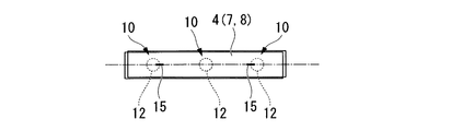
図1Aは、フランジ(重ね合せ部)1の延在する方向に抵抗スポット溶接により複数のスポット溶接部10を形成し、スポット溶接部10のナゲット12の端を横切ってレーザビームLBを照射してレーザビーム照射による溶融凝固部15を形成する状況の一例を示している。なお、フランジ1は、鋼板から形成された成形品(鋼板部材)2のフランジ2Fと、鋼板から形成された成形品(鋼板部材)3のフランジ3Fとを重ね合せて形成されている。
In FIG. 1A, a plurality of
一実施形態では、成形品2と成形品3に成形される鋼板のいずれか一方又は双方が、(a)マルテンサイト組織を含んだ高強度鋼板(例えば、1200MPa級以上の高強度鋼板)を冷間でプレス成形した鋼板部材、又は(b)ホットスタンプ材用鋼板をホットスタンプで成形することでマルテンサイト組織が生じたホットスタンプ材(例えば、引張強さ強度1200MPa以上の鋼板部材)である。すなわち、マルテンサイト組織を含む鋼板部材を少なくとも一枚含む。
In one embodiment, one or both of the steel sheets formed into the molded
高強度鋼板から成形された鋼板部材やホットスタンプ材の鋼板部材の重ね合せ部が抵抗スポット溶接されると、スポット溶接部にHAZ軟化部が形成される。このHAZ軟化部はスポット溶接部の強度が高強度鋼板(母材)より大幅に低下するが、レーザビーム照射によって溶融凝固部を形成する。これにより、HAZ軟化部が硬化してHAZ軟化部における応力集中に起因する破断が抑制されて、高強度鋼板やホットスタンプ材としての強度を充分に発揮できるようになる。 When the overlapping portion of the steel plate member formed from the high-strength steel plate or the steel plate member of the hot stamp material is subjected to resistance spot welding, a HAZ softened portion is formed in the spot welded portion. In this HAZ softened portion, the strength of the spot welded portion is significantly lower than that of a high-strength steel plate (base material), but forms a molten and solidified portion by laser beam irradiation. As a result, the HAZ softened portion is hardened and the breakage due to the stress concentration in the HAZ softened portion is suppressed, and the strength as a high-strength steel plate or hot stamp material can be sufficiently exhibited.
図1Bは、本発明を適用した3枚(複数)の鋼板部材を重ね合せた接合部の概略構成の一例を説明する図である。図1Bは、高強度鋼板5Hと、高強度鋼板6Hと、低強度鋼板7Lとを重ね合せて、抵抗スポット溶接によりナゲット12を有するスポット溶接部10を形成し、高強度鋼板5H側からレーザビームを照射して、ナゲット12を横切る溶融凝固部15が形成された状態を示している。なお、図1Bにおいて、高強度鋼板5H、高強度鋼板6H、低強度鋼板7Lの板厚は、それぞれt5、t6、t7である。
FIG. 1B is a diagram for explaining an example of a schematic configuration of a joint portion in which three (plural) steel plate members to which the present invention is applied are overlapped. In FIG. 1B, a high-
なお、この明細書において、高強度鋼板とは、「未成形の高強度鋼板」、「高強度鋼板を成形した鋼板部材」、「ホットスタンプ用鋼板をホットスタンプで成形したホットスタンプ材」を含むものとする。
また、低強度鋼板は、「未成形の低強度鋼板」、「低強度鋼板を成形した鋼板部材」を含むものとする。
また、鋼板には、「未成形の高強度鋼板」、「未成形の低強度鋼板」、「高強度鋼板を成形した鋼板部材」、「ホットスタンプ用鋼板をホットスタンプで成形したホットスタンプ材」、「低強度鋼板を成形した鋼板部材」を含むものとする。
In this specification, the high-strength steel sheet includes “unformed high-strength steel sheet”, “steel sheet member formed from a high-strength steel sheet”, and “hot stamp material formed from a hot stamping steel sheet by hot stamping”. Shall be.
The low-strength steel sheet includes “unformed low-strength steel sheet” and “steel sheet member formed from the low-strength steel sheet”.
In addition, steel sheets include "unformed high-strength steel sheets", "unformed low-strength steel sheets", "steel sheet members formed from high-strength steel sheets", and "hot stamp materials formed from hot stamped steel sheets". And “a steel plate member formed from a low-strength steel plate”.
図1Bにおいて、ナゲット12は、高強度鋼板5H、高強度鋼板6H、低強度鋼板7Lにわたってこれらを接合するように形成されている。
溶融凝固部15は、例えば、ナゲット12の端から外方に距離L1離れた位置からナゲット12を横切りナゲット12の端から外方に距離L2離れた位置まで形成されている。また、溶融凝固部15は、高強度鋼板5Hの板厚t5の全厚(100%)と、高強度鋼板6Hの板厚t6の高強度鋼板5Hから低強度鋼板7Lに至る中間位置まで形成されている。
ここで、ナゲット12の端とは、複数の鋼板部材を重ね合せて形成した重ね合せ部を鋼材表面から透過した場合におけるナゲット12の最大形状(外側の境界)をいう。
In FIG. 1B, the
The melt-solidified
Here, the end of the
図1Bに示した符号LD5、LD6は、ナゲット12の端から外方に1mm離れた位置における高強度鋼板5H、高強度鋼板6Hのそれぞれの溶融凝固部15の深さである。HAZ軟化部における破断を抑制するうえで、それぞれの高強度鋼板について、溶融凝固部15の深さ≧板厚の50%(ここでは、高強度鋼板5H、6Hのそれぞれについて、LD5≧t5の50%、LD6≧t6の50%)であることが効果的である。
なお、図1Bでは、高強度鋼板5H及び高強度鋼板6Hが高強度鋼板であり、高強度鋼板5Hは板厚の全厚(すなわち、LD5=板厚t5)にわたって溶融凝固部15が形成されている。したがって、高強度鋼板6Hにおける溶融凝固部15の深さLD6 ≧ (板厚t6の50%)とすることで充分な効果的が確保される。
Symbols LD5 and LD6 shown in FIG. 1B are the depths of the melt-solidified
In FIG. 1B, the high-
ここで、溶融凝固部15の深さLDを、ナゲット12の端から外方に1mm離れた位置で規定するのは、図14に示すように、スポット溶接部110のHAZ最軟化部103Aはナゲット112の端から外方に約1mm離れた位置に存在することから、HAZ最軟化部103A付近に溶融凝固部を形成することがHAZ軟化部を硬化させるのに効果的であることに基づいている。
Here, the depth LD of the melted and solidified
なお、図1Bは、溶融凝固部15が、重ね合せ部を鋼材表面から見た場合におけるナゲット12の中心部を通過し、ナゲット12の端を左右2か所で横切る例を示しているが、溶融凝固部15がナゲット12の端を横切る位置及び横切る数は2か所に限られることなく、1か所でもよいし3か所以上でもよい。また、2か所で横切る場合に、ナゲット12の中心部を挟んで延長上に位置してもよいが、ナゲット12の中心部を挟んで延長上にする必要はない。
FIG. 1B shows an example in which the melt-solidified
また、溶融凝固部15がナゲット12の端を2か所以上で横切る溶融凝固部15を形成する場合に、ナゲット12の端から1mm外方における溶融凝固部15の深さLDが、LD≧板厚の50%であることが好適であるが、ナゲット12の端を横切る溶融凝固部15の一部がLD ≧ 板厚の50%を満足していなくてもよい。また、溶融凝固部15がナゲット12の端から3mm以上の距離にわたって形成されていることが好適であるが、3mm以下でもよい。
Further, when the melt-solidified
図2Aは、本発明を、1500MPa級のホットスタンプ材(鋼板部材)と、1500MPa級のホットスタンプ材(鋼板部材)を2枚重ね合せした例を示す図である。より詳細には、図2Aは、ホットスタンプ材のフランジ4Aに抵抗スポット溶接により、ナゲット12を有するスポット溶接部10を形成し、スポット溶接部10にレーザビームを照射して溶融凝固部15を形成した例を示している。
FIG. 2A is a diagram showing an example in which the present invention is obtained by superposing two 1500 MPa class hot stamp materials (steel plate members) and two 1500 MPa class hot stamp materials (steel plate members). More specifically, FIG. 2A shows that the spot welded
図2Bは、図2AにおけるI−I断面を示す図であり、図2Cは図2Aに示したスポット溶接部の周辺を鋼材表面から見た模式図である。なお、説明の便宜のため、図2Cの中心線から左半分はスポット溶接部10にレーザビームが照射されていない従来の状態を、右半分はスポット溶接部10にレーザビームが照射されて溶融凝固部15が形成された状態を示している。
また、図3A、図3B、図3Cは、図2Cにおける破線A、破線B、破線Cで示した部分の硬さ分布を示す図である。
2B is a diagram showing a cross section taken along the line II in FIG. 2A, and FIG. 2C is a schematic view of the periphery of the spot welded portion shown in FIG. 2A as viewed from the steel surface. For convenience of explanation, the left half of the center line in FIG. 2C shows a conventional state in which the spot welded
3A, FIG. 3B, and FIG. 3C are diagrams showing the hardness distribution of the portions indicated by the broken lines A, B, and C in FIG. 2C.
従来のスポット溶接部10は、図2Cの左半分と同様であり、図3Aに示す破線Aで示す部分では、HAZ軟化部13が広い範囲にわたって形成されている。そのため、左右方向に付加される引張荷重に対して、HAZ軟化部13が広い範囲にわたって引張られることとなる。その結果、引張荷重に対する強度が低下して、引張荷重による破断が発生しやすくなる。
一方、図2Cの右半分に示すようなナゲット12とHAZ軟化部13の間に、ナゲット12の端を横切ってレーザビーム照射により溶融凝固部15が形成されると、図3Bに示す破線Bで示す部分は、溶融凝固部15によりHAZ軟化部13は硬化してHAZ軟化部13の範囲が小さくなる。その結果、HAZ軟化部13の幅が縮小する。その結果、スポット溶接部10の強度が向上して、引張強度が向上する。
一方、図2Cおよび図3Cに示す破線Cで示す部分では、溶融凝固部15を形成すると、HAZ軟化部15Aが形成されるが、HAZ軟化部15Aのは、引張荷重が作用する範囲が小さいことから引張強度に荷重あまりに影響しない。
The conventional spot welded
On the other hand, when the melted and solidified
On the other hand, in the portion indicated by the broken line C shown in FIGS. 2C and 3C, when the melt-solidified
また、図4A〜図4Cを参照して、本発明の効果の一例を説明する。
図4Aは、従来の抵抗スポット溶接による試験片T01であり、試験片T01にはナゲット12を有するスポット溶接部10が形成されている。
図4Bは、本発明の溶接方法による試験片T02であり、試験片T02にはナゲット12の二つの端を横切るレーザビーム照射による溶融凝固部15が形成されている。
図4Cは、試験片T01およびT02における応力−歪み線図であり、破線で示すAは試験片T01を、実線で示すBは試験片T02の結果を表している。
An example of the effect of the present invention will be described with reference to FIGS. 4A to 4C.
FIG. 4A shows a test piece T01 by conventional resistance spot welding, and a
FIG. 4B shows a test piece T02 obtained by the welding method of the present invention, and a melt-solidified
FIG. 4C is a stress-strain diagram for the test pieces T01 and T02. A shown by a broken line indicates the result of the test piece T01, and B shown by a solid line indicates the result of the test piece T02.
図4Cに示すように、スポット溶接部10にレーザビームを照射して溶融凝固部15を形成することにより、引張荷重を負荷した場合の限界破断ひずみは、スポット溶接部10に比べて大幅に向上し、例えば、衝突時のHAZにおける破断を抑制できる。
As shown in FIG. 4C, the limit fracture strain when a tensile load is applied is greatly improved by irradiating the spot welded
以上のように、スポット溶接部10のナゲット12を横切るように溶融凝固部15を形成して、図1Bに示すような構成とすることにより、抵抗スポット溶接だけの場合に引張荷重を受けて破断しやすいスポット溶接のHAZ軟化部の領域を低減することができる。これにより、引張荷重を受けたときの破断までの変形能を向上することができる。
As described above, the melt-solidified
図5A〜図5Dは、複数の鋼板を重ね合せる組み合わせに関する例と、スポット溶接部およびレーザビーム照射による溶融凝固部の関係を示す説明図である。 5A to 5D are explanatory diagrams illustrating an example of a combination of superposing a plurality of steel plates, and a relationship between a spot welded portion and a melted and solidified portion by laser beam irradiation.
図5Aは、鋼板の組み合わせの第1の例を示す説明図であり、低強度鋼板31L(板厚t31)と、高強度鋼板32H(板厚t32)とを重ね合せて高強度鋼板32H側からレーザビームを照射して溶融凝固部15(深さL15)が形成された場合を示している。図5Aにおいて、符号LD32は、高強度鋼板32Hにおける溶融凝固部15の深さを示している。
FIG. 5A is an explanatory view showing a first example of a combination of steel plates, and a low-
図5Aに示すように、第1の例では、高強度鋼板32Hは板厚の全厚(板厚t32の100%)、低強度鋼板31Lは板厚方向における高強度鋼板32H側から反対側表面に至る中間位置まで溶融凝固部15が形成されている。第1の例では、高強度鋼板は高強度鋼板32Hのみであり、溶融凝固部15の深さLD32は高強度鋼板32Hの板厚方向の全厚(LD32=板厚t32の100% > 板厚t32の50%)にわたって形成されているので、充分な効果を確保することができる。
As shown in FIG. 5A, in the first example, the high-
図5Bは、鋼板の組み合わせの第2の例を示す説明図であり、高強度鋼板31H(板厚t31)と、高強度鋼板32H(板厚t32)とを重ね合せて高強度鋼板32H側からレーザビームを照射して溶融凝固部15(深さL15)が形成された場合を示している。図5Bにおいて、符号LD31およびLD32は、それぞれ高強度鋼板31H、高強度鋼板32Hにおける溶融凝固部15の深さを示している。
FIG. 5B is an explanatory diagram showing a second example of the combination of steel plates, and the high-
図5Bに示すように、第2の例では、溶融凝固部15は、高強度鋼板32Hにおける深さLD32は板厚の全厚(LD32=板厚t32の100%)であり、高強度鋼板31Hは板厚方向における高強度鋼板32H側から反対側表面に至る中間位置まで溶融凝固部15が形成されている。第2の例では、高強度鋼板は高強度鋼板31H及び高強度鋼板32Hであり、溶融凝固部15は高強度鋼板32Hの板厚の全厚(LD32=板厚t32の100% > 板厚t32の50%)にわたって形成されているので、高強度鋼板31Hにおける深さLD31をLD31 ≧ (板厚t31の50%)とすることにより、充分な効果を確保することができる。
As shown in FIG. 5B, in the second example, in the melt-solidified
図5Cは、鋼板の組み合わせの第3の例を示す説明図であり、低強度鋼板31L(板厚t31)と、高強度鋼板32H(板厚t32)と、低強度鋼板33L(板厚t33)とを重ね合せて低強度鋼板31L側からレーザビームを照射して溶融凝固部15(深さL15)が形成された場合を示している。図5Cにおいて、符号LD32は、高強度鋼板32Hにおける溶融凝固部15の深さを示している。
FIG. 5C is an explanatory view showing a third example of the combination of steel plates, a low-
図5Cに示すように、第3の例では、溶融凝固部15は、低強度鋼板31Lの板厚の全厚と、高強度鋼板32Hの板厚方向における低強度鋼板31L側から低強度鋼板33L側に至る中間位置まで形成されている。第3の例では、高強度鋼板は高強度鋼板32Hのみであるので、高強度鋼板32Hにおける溶融凝固部15の深さLD32を、LD32 ≧ (板厚t32の50%)とすることにより、充分な効果を確保することができる。
As shown in FIG. 5C, in the third example, the melt-solidified
図5Dは、鋼板の組み合わせの第4の例を示す説明図であり、高強度鋼板31H(板厚t31)と、高強度鋼板32H(板厚t32)と、低強度鋼板33L(板厚t33)とを重ね合せて高強度鋼板31H側からレーザビームを照射して溶融凝固部15(深さL15)が形成された場合を示している。図5Dにおいて、符号LD31、LD32は、高強度鋼板31H、高強度鋼板32Hにおける溶融凝固部15の深さを示している。
FIG. 5D is an explanatory diagram showing a fourth example of a combination of steel plates, a high-
図5Dに示すように、第4の例では、溶融凝固部15は、高強度鋼板31Hの板厚の全厚(LD31=板厚t31の100%)にわたって形成されるとともに、高強度鋼板32Hの板厚方向における高強度鋼板31H側から低強度鋼板33L側に至る中間位置まで形成されている。第4の例では、高強度鋼板は高強度鋼板31H及び高強度鋼板32Hであるので、高強度鋼板32Hにおける溶融凝固部15の深さLD32を、LD32 ≧ (板厚t32の50%)とすることにより、充分な効果を確保することができる。
As shown in FIG. 5D, in the fourth example, the melt-solidified
一実施形態では、複数の鋼板部材同士を重ね合せ部で接合し、複数の鋼板部材の少なくとも一つがマルテンサイト組織を含む鋼板部材を、抵抗スポット溶接により接合された重ね合せ溶接部材を対象としている。例えば、自動車用車体を構成するモノコックボディやモノコックボディを構成するAピラー、Bピラー等の自動車用部品(Assy部品)をはじめとする種々の構造物の形成に適用される。 In one embodiment, a plurality of steel plate members are joined at an overlap portion, and a steel plate member including at least one of the plurality of steel plate members including a martensite structure is targeted for a lap weld member joined by resistance spot welding. . For example, the present invention is applied to the formation of various structures including automobile parts (Assy parts) such as monocoque bodies constituting automobile bodies and A pillars and B pillars constituting monocoque bodies.
鋼板部材の重ね合せ部は、一般的に、鋼板の縁に他の鋼板とのスポット溶接代として形成されるフランジ(重ね合せ部)であるが、フランジに限定されるものではなく、フランジと形状部等(フランジ以外の部分)を重ね合せた部分に抵抗スポット溶接されたものでもよい。 The overlapped portion of the steel plate member is generally a flange (overlapped portion) formed as a spot welding allowance with another steel plate at the edge of the steel plate, but is not limited to the flange, and the flange and shape Resistance spot welding may be performed on a portion where portions or the like (portions other than the flange) are overlapped.
マルテンサイト組織を含む鋼板部材としては、連続焼鈍設備でマルテンサイトを含む焼入れ組織とした高強度鋼板(例えば、引張強さ強度1200MPa級以上の高張力鋼板)の冷間プレス成形品や、ホットスタンプ用鋼板をオーステナイト温度以上に加熱し、水冷金型で成形しながら焼入れることで強度を高めた引張強さ強度1200MPa以上のホットスタンプ材が例示される。 As steel plate members including a martensite structure, a cold-press formed product of a high-strength steel sheet (for example, a high-strength steel sheet having a tensile strength of 1200 MPa class or more) that has been quenched by continuous annealing equipment and martensite, Examples include hot stamping materials having a tensile strength of 1200 MPa or more, in which the steel sheet is heated to an austenite temperature or higher and quenched while being molded with a water-cooled mold.
HAZ軟化によるスポット溶接の破断のリスクが生じるマルテンサイト組織が形成される高強度鋼板で効果があるが、引張強さ強度1200MPa以上の高強度鋼板で大きな効果があることから引張強さ強度の下限は1200MPaとすることが好適である。また、引張強さ強度の上限は特に設定不要であるが、上限設定する場合は実用的に約2000MPaである。 This is effective for high-strength steel sheets in which a martensite structure is formed, which causes the risk of fracture of spot welding due to HAZ softening, but it has a large effect on high-strength steel sheets with a tensile strength of 1200 MPa or more, so the lower limit of tensile strength strength. Is preferably 1200 MPa. The upper limit of the tensile strength strength is not particularly required to be set, but when the upper limit is set, it is practically about 2000 MPa.
また、鋼板の板厚に制限を設定する必要はないものの、実用的な観点からすると、下限は0.7mmとすることができ、上限は2.6mmとすることが好適である。 Further, although it is not necessary to set a limit on the thickness of the steel sheet, from a practical viewpoint, the lower limit can be 0.7 mm, and the upper limit is preferably 2.6 mm.
引張強さ強度1200MPa以上の高強度鋼板は、冷延材の場合には、表面にめっきがされていない非めっき鋼板もしくは合金化溶融亜鉛めっき(GAめっき)、溶融亜鉛めっき(GIめっき)などの亜鉛系めっきで被覆された鋼板が対象とされる。
ホットスタンプ材の場合には、非めっき、アルミめっきもしくは鉄とアルミの金属間化合物、もしくは、鉄亜鉛固溶層と酸化亜鉛層により被覆された鋼板部材が対象とされる。
In the case of a cold-rolled material, a high-strength steel sheet having a tensile strength of 1200 MPa or more is a non-plated steel sheet that is not plated on the surface, alloyed hot dip galvanizing (GA plating), hot dip galvanizing (GI plating), etc. Steel sheets coated with zinc-based plating are targeted.
In the case of a hot stamp material, a steel plate member covered with non-plating, aluminum plating, an intermetallic compound of iron and aluminum, or an iron zinc solid solution layer and a zinc oxide layer is targeted.
上記の高強度鋼板と重ね合せられる鋼板は、引張強さ強度1200MPa級以上の高強度鋼板やホットスタンプ材でもよいし、引張強さ強度が270MPa〜980MPa級の鋼板でもよい。また、2つに限らず3つ以上の複数枚を重ね合せてもよい。 The steel plate to be overlaid with the above-described high-strength steel plate may be a high-strength steel plate or hot stamp material having a tensile strength strength of 1200 MPa or higher, or a steel plate having a tensile strength strength of 270 MPa to 980 MPa. Moreover, you may overlap not only two but 3 or more several sheets.
以下、抵抗スポット溶接に関して、詳細に説明する。
抵抗スポット溶接工程は、複数の鋼板部材を互いに重ね合せて、重ね合せ部に抵抗スポット溶接をすることにより、ナゲットを有するスポット溶接部を形成する。
Hereinafter, the resistance spot welding will be described in detail.
In the resistance spot welding step, a plurality of steel plate members are overlapped with each other, and resistance spot welding is performed on the overlapped portion, thereby forming a spot welded portion having a nugget.
抵抗スポット溶接の溶接条件は、特に制限はないが、少なくとも接合対象の鋼板部材に、ナゲット径が4√t以上7√t以下(t:重ね面において薄い側の板厚(mm))となるナゲットが形成されるように適宜設定すればよい。
例えば、単相交流スポット溶接機もしくはインバータ直流スポット溶接機を用いて、溶接電極の先端直径:6〜8mm、先端の曲率半径R:40mm、加圧力:2.5〜6.0kN、溶接電流の電流値:7〜11kA、通電時間:10/60秒〜40/60秒の範囲で適宜設定して、重ね合せ部に上記ナゲットを形成すればよい。なお、スポット溶接条件は、上記条件に限定されるものではなく、鋼種や板厚等に応じて適宜設定することができる。
The welding conditions for resistance spot welding are not particularly limited, but at least the steel plate members to be joined have a nugget diameter of 4√t or more and 7√t or less (t: plate thickness (mm) on the thin side of the overlapping surface). What is necessary is just to set suitably so that a nugget may be formed.
For example, using a single-phase AC spot welder or an inverter DC spot welder, the tip diameter of the welding electrode: 6-8 mm, the radius of curvature R of the tip: 40 mm, the applied pressure: 2.5-6.0 kN, the welding current What is necessary is just to set suitably in the range of electric current value: 7-11kA, energization time: 10/60 second-40/60 second, and just to form the said nugget in an overlap part. In addition, spot welding conditions are not limited to the said conditions, According to steel grade, plate | board thickness, etc., it can set suitably.
抵抗スポット溶接のピッチは、通常、20〜60mm程度であるが、これに限定されるものではなく、対象とされる構造物やその部位に応じて適宜設定すればよい。 The pitch of resistance spot welding is usually about 20 to 60 mm, but is not limited to this, and may be appropriately set according to the target structure and its part.
以下、レーザビーム照射による溶融凝固部形成に関して、詳細に説明する。 溶融凝固部形成工程で、重ね合せ部にレーザビームを照射して、抵抗スポット溶接により形成したスポット溶接部のナゲットと、ナゲットの外方に位置されるHAZ又は母材との間にナゲットの端を横切る溶融凝固部を形成する。 Hereinafter, the formation of the melted and solidified portion by laser beam irradiation will be described in detail. In the melt-solidified part forming step, the end of the nugget is placed between the nugget of the spot welded part formed by resistance spot welding by irradiating the overlapped part with the laser beam and the HAZ or base material positioned outside the nugget A melt-solidified part is formed across.
すなわち、抵抗スポット溶接を行った後に重ね合せ部にレーザビームを照射して、ナゲットの周囲に形成されたHAZ軟化部を横切って溶融凝固部を形成することで、HAZ軟化部を硬化させる。その結果、溶融凝固部によりHAZ軟化部が分断されて、想定応力方向におけるHAZ軟化部に起因する強度低下が抑制される。 That is, after performing the resistance spot welding, the overlapped portion is irradiated with a laser beam to form a melt-solidified portion across the HAZ softened portion formed around the nugget, thereby hardening the HAZ softened portion. As a result, the HAZ softened part is divided by the melt-solidified part, and the strength reduction due to the HAZ softened part in the assumed stress direction is suppressed.
以下、図6A〜図6Dを参照して、本発明を自動車用部品に適用する例を説明する。図6A〜図6Cは、自動車用車体を構成するモノコックボディへの適用例であり、側面衝突が発生した場合にキャビン内の乗員を保護する重要部材(自動車用部品)に適用した例を示す図である。 Hereinafter, with reference to FIGS. 6A to 6D, an example in which the present invention is applied to an automotive part will be described. 6A to 6C are examples of application to a monocoque body constituting an automobile body, and show an example of application to an important member (automobile part) that protects an occupant in a cabin when a side collision occurs. It is.
図6Aは、本発明に係る重ね溶接部材を、Bピラー41に適用した例を示す図である。Bピラー41のフランジには、フランジが延在する方向に沿って複数のスポット溶接部10が形成されるとともに、複数のスポット溶接部10を横切って溶融凝固部15がレーザビーム照射により形成されている。
FIG. 6A is a diagram showing an example in which the lap weld member according to the present invention is applied to the
また、例えば、Bピラー41の場合には、Bピラー41のフランジ(重ね合せ部)の鋼板部材端面に沿った方向を想定応力方向とするとよい。また、Bピラー41のフランジは、下部が車体の前後方向に湾曲しているが、フランジの鋼板部材端面の湾曲に沿う方向(例えば、それぞれのスポット溶接部10に最も近接する鋼板部材端面の接線方向)を想定応力方向とするとよい。なお、図6Aに示すように、溶融凝固部15が複数形成されていてもよいし、溶融凝固部15が通過しないスポット溶接部10Aがあってもよい。
For example, in the case of the
図6Bは、本発明に係る重ね溶接部材を、Aピラー40、Bピラー41及びルーフレール42に適用した例を示す図である。Aピラー40、Bピラー41及びルーフレール42には、それぞれのフランジが延在する方向に沿って複数のスポット溶接部10が形成されるとともに、複数のスポット溶接部10を横切ってレーザビーム照射による溶融凝固部15が形成されている。
FIG. 6B is a diagram illustrating an example in which the lap weld member according to the present invention is applied to the
また、図6Bに示すように、Bピラー41とAピラー40との接続部分や、Bピラー41とルーフレール42との接続部分のように、湾曲をともなうフランジでは、湾曲したフランジに沿って複数のスポット溶接部10が形成され、レーザビーム照射による溶融凝固部15はこれら複数のスポット溶接部10を横切って形成されている。なお、上記湾曲部分では、図6Aの場合と同様に、フランジの鋼板部材端面の湾曲方向(例えば、それぞれのスポット溶接部10に最も近接する鋼板部材端面の接線方向)を想定応力方向とするとよい。また、溶融凝固部15は複数形成されてもよいし、溶融凝固部15が通過しないスポット溶接部があってもよい。
In addition, as shown in FIG. 6B, in a flange with a curvature such as a connection portion between the
図6Cは、本発明に係る重ね溶接部材を、Aピラー40及びサイドシル43に適用した例を示す図である。サイドシル43のフランジには、フランジが延在する方向に沿って複数のスポット溶接部10が形成されるとともに、例えば、隣接する2つのスポット溶接部10を横切るレーザビーム照射による溶融凝固部15を部分的に分断して間隙が形成されている。このように、溶融凝固部15を分断して、溶融凝固部15の間に母材のままの部分を残すことにより、高強度鋼板の有する靱性を発揮させることが可能となる。このような溶融凝固部15を分断して形成した間隙による効果は、図6A、図6Bに示した例においても同様である。
FIG. 6C is a diagram showing an example in which the lap welding member according to the present invention is applied to the
図6A〜図6Cに示すようなキャビンの周囲に配置される構造部材に本発明を適用することにより、これらの構造部材がスポット溶接部10のHAZ軟化に起因する破断を抑制することができ、側面衝突に対する安全性を高めることができる。また、溶融凝固部15は、想定応力方向に対する交差角度θを±30°以内に形成することが好適である。
By applying the present invention to structural members arranged around the cabin as shown in FIGS. 6A to 6C, these structural members can suppress breakage due to the HAZ softening of the
また、図6Dは、本発明に係る重ね溶接部材を、前突や後突が発生した場合に乗員を保護するバンパーリインフォース44に適用した例を示す図である。
図6Dに示すバンパーレインフォース44では、バンパーリインフォース44の本体の内部に断面を保持するためのバルクヘッド45が抵抗スポット溶接されてスポット溶接部10が形成されている。このバンパーリインフォース44では、前突又は後突発生時にバンパーリインフォース44の長手方向と交差する前後方向に屈曲する力が作用する。このため、バンパーリインフォース44の長手方向を想定応力方向として、バンパーリインフォース44の長手方向との交差角度θが±30°以内で交差するようにレーザビームを照射して溶融凝固部15を形成することが好適である。
Moreover, FIG. 6D is a figure which shows the example applied to the
In the
なお、衝突により曲げを受ける部材の場合、想定応力方向は、鋼板部材端面に沿う方向であり、部材にキャビンの内側と外側を結んだ面と垂直な方向に作用する。 In the case of a member that is bent by a collision, the assumed stress direction is a direction along the end surface of the steel plate member, and acts in a direction perpendicular to the surface connecting the inside and outside of the cabin to the member.
以下、図7A〜図7Lを参照して、スポット溶接部と溶融凝固部の形成状況の例について説明する。図7A〜図7Lは、本発明に係るスポット溶接部と溶融凝固部の形成状況を例示する概略図である。 Hereinafter, with reference to FIG. 7A-FIG. 7L, the example of the formation condition of a spot weld part and a fusion | melting solidification part is demonstrated. 7A to 7L are schematic views illustrating the formation status of spot welded portions and melt-solidified portions according to the present invention.
図7Aは、本発明に係るスポット溶接部と溶融凝固部の形成状況の第1の例を示す概略図であり、成形品(鋼板部材)5のフランジ部5Fと、成形品(鋼板部材)6のフランジ部6Fとを重ね合わせたフランジ4に形成したスポット溶接部10のナゲット12にレーザ照射による溶融凝固部15を形成する例である。
FIG. 7A is a schematic diagram showing a first example of the formation status of the spot welded portion and the melt-solidified portion according to the present invention, and the
溶融凝固部15の形成方向は、図7Aに示すように、フランジ(継ぎ手部)4の延在する方向又は想定応力方向(図7Aにおける左右方向)に対して±30°以内の角度θとなる範囲であることが望ましい。交差角度θが±15°以内となる範囲は、より好適である。
As shown in FIG. 7A, the formation direction of the melt-solidified
例えば、図6A〜図6Dに示したような、Aピラー、Bピラー、ルーフレール、サイドシル、バンパーリインフォースなどは、筒状の閉断面に接続されたフランジを接合代として構成されている。衝突時にはフランジの鋼板部材端面に沿う方向に引張荷重を受けることが多い。このため、フランジに沿う方向にレーザビームを照射してスポット溶接部10のナゲット12を横切る溶融凝固部15を形成することが好適である。また、長尺部品の内部の場合、部品の長手方向に沿う方向に引張荷重の受けることが多く、部品の長手方向に沿う方向にレーザビームを照射してスポット溶接部10のナゲット12を横切る溶融凝固部15を形成することが好適である。
For example, A pillars, B pillars, roof rails, side sills, bumper reinforcements, and the like as shown in FIGS. 6A to 6D are configured with a flange connected to a cylindrical closed cross section as a joint allowance. In the event of a collision, a tensile load is often applied in the direction along the end face of the steel plate member of the flange. For this reason, it is preferable to form a melt-solidified
図7Bは、本発明に係るスポット溶接部と溶融凝固部の形成状況の第2の例を示す概略図である。
図7Bに示すように、例えばフランジで接合されない部材7を重ね合せ部材8により部分補強する場合のスポット溶接部10や、部材にバルクヘッドを重ね合せた場合のスポット溶接部では、一般的に、部材の長手方向に引張荷重を受ける。このため、部材等の長手方向に沿ってレーザビームを照射して溶融凝固部15を形成することが好適である。
FIG. 7B is a schematic diagram showing a second example of the formation status of spot welds and melt-solidified portions according to the present invention.
As shown in FIG. 7B, for example, in the spot welded
図7Cは、本発明に係るスポット溶接部と溶融凝固部の形成状況の第3の例を示す概略図である。
図7Cに示すように、レーザビームの照射により形成される溶融凝固部15は、ナゲット12の中央付近を通過することが好適であるが、必ずしもスポット溶接部10のナゲット12の中心と一致する必要はない。
FIG. 7C is a schematic diagram showing a third example of the formation status of spot welds and melt-solidified portions according to the present invention.
As shown in FIG. 7C, it is preferable that the melted and solidified
図7Dは、本発明に係るスポット溶接部と溶融凝固部の形成状況の第4の例を示す概略図である。
図7Dに示すように、溶融凝固部15は、レーザビームの照射の効率を考慮すると、直線状に形成されることが望ましいが、屈曲部を有する曲線状に形成されていてもよいし、溶融凝固部15の長さを長くするために波状等に形成してもよい。このような場合に、想定応力方向と交差角度θが±30°以内で交差するようにすると好適である。
FIG. 7D is a schematic diagram showing a fourth example of the formation status of spot welds and melt-solidified portions according to the present invention.
As shown in FIG. 7D, the melted and solidified
図7Eは、本発明に係るスポット溶接部と溶融凝固部の形成状況の第5の例を示す概略図である。
溶融凝固部15は、図7A〜図7Dに示したように個々のスポット溶接部10に個別に形成されてもよいが、図7Eに示すように、複数のスポット溶接部10を接続するように連続して形成してもよい。また、1つのスポット溶接部10に対して複数(例えば、2本)の溶融凝固部15を形成されていてもよい。
FIG. 7E is a schematic diagram showing a fifth example of the formation status of spot welds and melt-solidified portions according to the present invention.
The melt-solidified
図7Fは、本発明に係るスポット溶接部と溶融凝固部の形成状況の第6の例を示す概略図である。
図7Fに示すように、レーザビームの照射による溶融凝固部15は、スポット溶接部10のナゲットに対して左右均等に形成されていなくともよい。ただし、溶融凝固部15は、スポット溶接部10のナゲット12の両側に存在し、かつ短い側が、ナゲットの端から溶融凝固部15の端までの距離が3mm以上であることが望ましい。ナゲットの端から溶融凝固部15の端までの距離を3mm以上とすると、HAZ軟化部にひずみが集中するのを充分に抑制することができるからである。溶融凝固部15は前述のように複数のスポット溶接部10を横断してもよい。
FIG. 7F is a schematic diagram illustrating a sixth example of the formation status of spot welds and melt-solidified portions according to the present invention.
As shown in FIG. 7F, the melted and solidified
レーザビームの照射の条件は、特に制限はなく、必要とされる箇所に、前述した所定の溶融凝固部15が得られればよい。レーザ溶接機としてディスクレーザ、ファイバーレーザ、ダイレクトダイオードレーザ、YAGレーザ、炭酸ガスレーザを用い、ビーム径0.15〜0.9mmの範囲とし、出力1〜10kWの範囲とし、溶接速度1〜15m/minの範囲とすることが例示される。
The conditions for laser beam irradiation are not particularly limited as long as the predetermined melted and solidified
溶接は、一般的なトーチによる溶接でもよく、リモート溶接や、クランプ装置を持ったLaser seam stepperを用いてもよい。レーザビームの照射条件は、例示した条件には限定されず、前述した所定の溶融凝固部15が得られる照射条件であればよい。
The welding may be a general torch welding, or remote welding or a laser seam stepper having a clamp device. The irradiation conditions of the laser beam are not limited to the exemplified conditions, and may be irradiation conditions that can obtain the predetermined melted and solidified
レーザビームの照射は、全てのスポット溶接部10に実施する必要はない。衝突によりスポット溶接部10のHAZ軟化部における破断の虞があるスポット溶接部10のみに実施すればよい。
The laser beam irradiation need not be performed on all spot welds 10. What is necessary is just to implement only to the
図7Gは、本発明に係るスポット溶接部と溶融凝固部の形成状況の第7の例を示す概略図である。
図7Gに示すように、隣接する2つのスポット溶接部10の間にレーザビームを照射し、スポット溶接部10を通過する溶融凝固部15と、スポット溶接部10を通過しない溶融凝固部15(レーザ溶接部)とが形成されている例を示している。このように、隣接する2つのスポット溶接部10の間のレーザ溶接部は、重ね合せ部の浮き上がりにより隙間が形成されてスポット溶接により充分な接続ができない場合でも、溶接間隔を短くして部材のねじり剛性を向上することが可能であり望ましい。
FIG. 7G is a schematic diagram showing a seventh example of the formation status of spot welds and melt-solidified portions according to the present invention.
As shown in FIG. 7G, a laser beam is irradiated between two
図7Hは、本発明に係るスポット溶接部と溶融凝固部の形成状況の第8の例を示す概略図である。
図7Hに示すように、必要に応じて、スポット溶接部10を複数の溶融凝固部15が並列に通過するように配置してもよい。図7Hでは、溶融凝固部15が2本の例を示したが、3本以上でもよい。
FIG. 7H is a schematic view showing an eighth example of the formation status of spot welds and melt-solidified portions according to the present invention.
As shown in FIG. 7H, if necessary, the spot welded
図7Iは、本発明によるスポット溶接部と溶融凝固部の形成状況の第9の例を示す概略図である。
図7Iに示すように、レーザビームの照射により形成される溶融凝固部15の端を、応力集中を避けるため屈曲させた形状としてもよいし、始終端のビード幅を太くしてもよい。
FIG. 7I is a schematic view showing a ninth example of the formation status of spot welds and melt-solidified portions according to the present invention.
As shown in FIG. 7I, the end of the melt-solidified
図7Jは、本発明に係るスポット溶接部と溶融凝固部の形成状況の第10の例を示す概略図である。
図7Jに示すように、スポット溶接部10に対して互いに離間する側(互いに外側となる側)の位置に溶融凝固部15を形成してもよい。このようにスポット溶接部10に対して反対向きの溶融凝固部15を形成する場合に、それらの間に一つ又は複数のスポット溶接部10、溶融凝固部15が形成されたスポット溶接部10、スポット溶接部10を通過しない溶融凝固部15(レーザ溶接部)を配置してもよい。
FIG. 7J is a schematic diagram showing a tenth example of the formation status of spot welds and melt-solidified portions according to the present invention.
As shown in FIG. 7J, the melt-solidified
図7Kは、本発明に係るスポット溶接部と溶融凝固部の形成状況の第11の例を示す概略図である。
図7Kに示すように、スポット溶接部10に対して互いに近接する側(互いに内側となる側)の位置に溶融凝固部15を形成してもよい。このようにスポット溶接部10に対して互いに近接する向きの溶融凝固部15を形成する場合に、それらの間に一つ又は複数のスポット溶接部10、溶融凝固部15が形成されたスポット溶接部10、スポット溶接部10を通過しない溶融凝固部15(レーザ溶接部)を配置してもよい。
FIG. 7K is a schematic view showing an eleventh example of the formation status of spot welds and melt-solidified portions according to the present invention.
As shown in FIG. 7K, the melted and solidified
図7Lは、本発明に係るスポット溶接部と溶融凝固部の形成状況の第12の例を示す概略図である。
図7Lに示すように、隣接する溶融凝固部15を、スポット溶接部10に対して同じ側(図7Lでは左側)に形成してもよい。このようにスポット溶接部10に対して同じ側に形成する場合に、それらの間に一つ又は複数のスポット溶接部10、溶融凝固部15が形成されたスポット溶接部10、スポット溶接部10を通過しない溶融凝固部15(レーザ溶接部)を配置してもよい。
FIG. 7L is a schematic view showing a twelfth example of the formation status of spot welds and melt-solidified portions according to the present invention.
As shown in FIG. 7L, adjacent melt-solidified
本発明の抵抗スポット溶接及びスポット溶接部10のナゲット12への溶融凝固部15の形成は、例えば、自動車製造工程における車体溶接工程に適用可能である。車体の溶接などの流れ作業では、重ね溶接部材の位置決め及びクランプして抵抗スポット溶接した後に、引き続き抵抗スポット溶接による増し打ちやレーザビーム照射を行うと再位置決めや再クランプに起因するスポット溶接部に対するレーザビーム照射の位置ずれが防止できる点で好適である。
また、より好ましくは、抵抗スポット溶接を行ったステーションと同じステーションでレーザビーム照射を行うことが好適である。
The formation of the melted and solidified
More preferably, it is suitable to perform laser beam irradiation at the same station as the station where resistance spot welding was performed.
次に、図8A〜図8Fを参照して、高強度鋼板と低強度鋼板とを重ね合せて、レーザビームを照射して溶融凝固部を形成する場合の例を説明する。図8A〜図8Cは、いずれも、重ね合わされる2枚の鋼板が高強度鋼板と低強度鋼板との組み合わせの場合の説明図であり、非めっきの高強度鋼板(1500MPa)61Hと非めっきの低強度鋼板(270MPa)62Lとの重ね合せの例を示している。 Next, an example in which a high-strength steel plate and a low-strength steel plate are overlapped and irradiated with a laser beam to form a melt-solidified portion will be described with reference to FIGS. 8A to 8F. 8A to 8C are explanatory diagrams in the case where the two steel plates to be stacked are a combination of a high-strength steel plate and a low-strength steel plate, and non-plated high-strength steel plate (1500 MPa) 61H and non-plated steel plate. An example of superposition with a low-strength steel plate (270 MPa) 62L is shown.
図8Aは、第1の例を説明する図であり、第1の例は、非めっきの高強度鋼板61Hと非めっきの低強度鋼板62Lを重ね合せて、高強度鋼板61H側からレーザビームLBを照射して、非めっきの高強度鋼板61H及び非めっきの低強度鋼板62Lの板厚の全厚に溶融凝固部15を形成する場合を示している。この場合、高強度鋼板61Hにおける溶融凝固部15の深さLD61は高強度鋼板61Hの板厚に対して100%である。
FIG. 8A is a diagram for explaining the first example. In the first example, the non-plated high-
図8Bは、第2の例を説明する図であり、第2の例は、非めっきの高強度鋼板61Hと非めっきの低強度鋼板62Lを重ね合せて、低強度鋼板62L側からレーザビームLBを照射して、非めっきの高強度鋼板61H及び非めっきの低強度鋼板62Lの板厚の全厚に溶融凝固部15を形成する場合を示している。この場合、高強度鋼板61Hにおける溶融凝固部15の深さLD61は高強度鋼板61Hの板厚に対して100%である。
FIG. 8B is a diagram for explaining the second example. In the second example, the non-plated high-
図8Cは、第3の例を説明する図であり、第3の例は、非めっきの高強度鋼板61Hと非めっきの低強度鋼板62Lを重ね合せて、高強度鋼板61H側からレーザビームLBを照射して、非めっきの高強度鋼板61Hの表面から非めっきの低強度鋼板62Lに到達する途中まで溶融凝固部15を形成する場合を示している。この場合、高強度鋼板61Hにおける溶融凝固部15の深さLD61を板厚の50%以上とすることが好適である。
FIG. 8C is a diagram for explaining the third example. In the third example, the non-plated high-
図8Dは、第4の例を説明する図であり、第4の例は、非めっきの高強度鋼板(1500MPa)61Hと非めっきの高強度鋼板(1500MPa)62Hとを重ね合せて、高強度鋼板61H側からレーザビームLBを照射して溶融凝固部15を形成する場合を示している。この場合、高強度鋼板61Hにおける溶融凝固部15の深さLD61は高強度鋼板61Hの板厚に対して100%である。
図8Dに示すように、高強度鋼板61Hと高強度鋼板62Hとを重ね合せる場合は、高強度鋼板61Hの板厚の全厚と高強度鋼板62Hにおける深さLD62が高強度鋼板62Hの板厚の50%以上となる溶融凝固部15を形成することが好適である。
FIG. 8D is a diagram for explaining a fourth example. In the fourth example, non-plated high-strength steel plate (1500 MPa) 61H and non-plated high-strength steel plate (1500 MPa) 62H are overlapped to obtain high strength. The case where the laser beam LB is irradiated from the
As shown in FIG. 8D, when the high-
図8E、図8Fは、低強度鋼板、高強度鋼板、低強度鋼板の順に3枚重ね合せられる場合の例を示している。 FIG. 8E and FIG. 8F show an example in which three low strength steel plates, high strength steel plates, and low strength steel plates are stacked in this order.
図8Eは、第5の例を説明する図であり、第5の例は、非めっきの低強度鋼板(270MPa)61L、非めっきの高強度鋼板(1500MPa)62H、非めっきの低強度鋼板(590MPa)63Lを重ね合せて、低強度鋼板61L側からレーザビームLBを照射して溶融凝固部15を形成する場合を示している。この場合、溶融凝固部15は、低強度鋼板61L、高強度鋼板62H、低強度鋼板63Lの板厚に対して100%であり、高強度鋼板62Hにおける溶融凝固部15の深さLD62が板厚の50%以上であるので好適である。
FIG. 8E is a diagram for explaining a fifth example. In the fifth example, a non-plated low-strength steel plate (270 MPa) 61L, a non-plated high-strength steel plate (1500 MPa) 62H, a non-plated low-strength steel plate ( 590MPa) 63L is overlapped, and the laser beam LB is irradiated from the low-
図8Fは、第6の例を説明する図であり、第6の例は、非めっきの低強度鋼板(270MPa)61L、非めっきの高強度鋼板(1500MPa)62H、非めっきの低強度鋼板(590MPa)63Lを重ね合せて、低強度鋼板61L側からレーザビームLBを照射して溶融凝固部15を形成する場合を示している。この場合、図8Fに示すように、溶融凝固部15は、低強度鋼板61Lの板厚の全厚と、高強度鋼板62Hの板厚の低強度鋼板61Lから低強度鋼板63Lに到達する途中まで形成されている。高強度鋼板62Hにおける溶融凝固部15の深さLD62を高強度鋼板62Hの板厚の50%以上とすることが好適である。
FIG. 8F is a diagram for explaining a sixth example. In the sixth example, a non-plated low strength steel plate (270 MPa) 61L, a non-plated high strength steel plate (1500 MPa) 62H, a non-plated low strength steel plate ( 590MPa) 63L is overlapped, and the laser beam LB is irradiated from the low-
(参考例)
次に、本発明の参考例について説明する。
上記第1の実施の形態は、鋼板が非めっき鋼板である場合であるが、代表的な亜鉛めっき鋼板であるGAめっき、GIめっきを含んだ鋼板の組み合わせの場合に、抵抗スポット溶接によりスポット溶接部10を形成して、スポット溶接部10にレーザビームLBを照射することにより、スポット溶接部10の穴あき欠陥が発生する可能性があることが判明した。以下、図9A、図9Bを参照して、スポット溶接部10に対するレーザ照射の影響について説明する。
(Reference example)
Next, reference examples of the present invention will be described.
In the first embodiment, the steel plate is a non-plated steel plate, but in the case of a combination of steel plates including GA plating and GI plating, which are typical galvanized steel plates, spot welding is performed by resistance spot welding. It was found that by forming the
図9Aは非めっきの高強度鋼板(1500MPa)と非めっきの低強度鋼板(440MPa)との重ね合せ部に形成したスポット溶接部10と溶融凝固部15を示す図である。非めっき鋼板の場合には、図9Aに示すように、穴あき欠陥は発生しない。
FIG. 9A is a view showing a spot welded
一方、図9Bは、非めっきの高強度鋼板(1500MPa)と合金化溶融亜鉛めっきされた低強度鋼板(440MPa)との重ね合せ部に形成したスポット溶接部10に溶融凝固部15を形成した例を示す図である。
合金化溶融亜鉛めっき鋼板の場合には、図9Bに示すように、溶融凝固部に穴あき欠陥15Hが発生する可能性があり、この穴あき欠陥15Hがスポット溶接部10の強度を低下させて、自動車が衝突した場合に破断の起点となることで、高強度鋼板の強度を充分に発揮できない可能性があることを見出した。
On the other hand, FIG. 9B shows an example in which the melt-solidified
In the case of an alloyed hot-dip galvanized steel sheet, as shown in FIG. 9B, there is a possibility that a holed
図9Bに示した穴あき欠陥15Hの発生する原因について、発明者らが鋭意研究した結果、穴あき欠陥15Hが、図10に示すようなスポット溶接部10の密着部16において発生するとの知見を得た。図10に示す密着部16は、ナゲット12よりも外方に位置され、スポット溶接部10において、溶融をともなわずに圧力により接合された部分である。
As a result of intensive studies by the inventors on the cause of the occurrence of the
穴あき欠陥15Hは、レーザビームLBを照射して溶融凝固部15を形成する際に、亜鉛めっきが形成された密着部16がレーザビームLB照射により溶融され、亜鉛が爆発的に気化して溶融鉄を吹き飛ばすことが原因であると推察される。
When the holed
参考例には、合金化溶融亜鉛めっき被膜もしくは溶融亜鉛めっき被膜が形成された亜鉛めっき鋼板を含む鋼板部材を接合することを対象としている。 The reference example is intended to join a steel sheet member including a galvanized steel sheet on which an alloyed hot-dip galvanized film or a hot-dip galvanized film is formed.
発明者らは、上記問題点について研究の結果、これらのGAめっきやGIめっきを含んだ鋼板を含む場合は、レーザビームLBの照射による溶融凝固部15の深さを、GAめっきもしくはGIめっきとの重ね面のスポット溶接の密着部16を溶融させないように制御することで、穴あき欠陥15Hが発生しない良好な溶接継手が得られるとの知見を得た。
As a result of research on the above problems, the inventors have determined that the depth of the melt-solidified
なお、非メッキ、アルミめっき、鉄アルミの金属間化合物、鉄亜鉛固溶層と酸化亜鉛相からなる皮膜の鋼板では被膜の沸点が高いことから、重ね合せ面の皮膜に起因する溶接欠陥が発生しにくい。また、スポット溶接部10のナゲット12の端から溶融凝固部15の外方に1mm離れた位置における溶融凝固部15の深さLDは、高強度鋼板の板厚の50%以上とすることが好適である。
In addition, non-plated, aluminum-plated, iron-aluminum intermetallic compounds, steel sheets with a coating consisting of an iron-zinc solid solution layer and a zinc oxide phase have a high boiling point, resulting in weld defects caused by the coating on the overlapping surface. Hard to do. Further, the depth LD of the molten solidified
参考例において、複数の鋼板部材が、例えば、マルテンサイト組織を有する鋼板やホットスタンプ材を含むかどうか、特に引張強さ強度1200MPa以上の高強度鋼板を含むかどうかは、任意に設定することができ、高強度鋼板を含まない構成とすることもできる。また、非めっき、アルミめっき、鉄アルミの金属間化合物、鉄亜鉛固溶層と酸化亜鉛相からなる皮膜が形成された鋼板からなる鋼板部材を組み合わせてもよい。 In the reference example, whether or not the plurality of steel plate members include, for example, a steel plate having a martensite structure or a hot stamp material, in particular, whether a high strength steel plate having a tensile strength of 1200 MPa or more can be arbitrarily set. It can also be set as the structure which does not contain a high strength steel plate. Moreover, you may combine the steel plate member which consists of a steel plate in which the film | membrane which consists of a non-plating, aluminum plating, an iron-aluminum intermetallic compound, an iron zinc solid solution layer, and a zinc oxide phase was formed.
また、参考例では、複数の鋼板部材を互いに重ね合せて、抵抗スポット溶接によりナゲット12を有するスポット溶接部10を形成し、レーザビームLBを照射して、溶融凝固部15がナゲット12を横切り、例えば、ナゲット12の端から溶融凝固部15のナゲット外方における端までの距離が、3mm以上離れた位置との間にナゲット12の端を横切る溶融凝固部15を形成する。
In the reference example, a plurality of steel plate members are overlapped with each other, the spot welded
まず、レーザビームを照射する重ね合せ鋼板部材が全て、非めっき、アルミめっき、鉄アルミの金属間化合物、鉄亜鉛固溶層と酸化亜鉛相からなる皮膜が形成された鋼板からなる鋼板部材である場合、レーザビームの照射により形成される溶融凝固部15は、ナゲット12の端から外方に1mm離れた位置における溶融凝固部15の深さLDを、全ての高強度鋼板に関してそれぞれの板厚の50%以上とすることで、HAZ最軟化部の硬さが改善される。
First, all the laminated steel plate members that irradiate a laser beam are steel plate members made of non-plated, aluminum plated, iron-aluminum intermetallic compound, a steel plate on which a film composed of a solid solution layer of iron zinc and a zinc oxide phase is formed. In this case, the melted and solidified
溶融凝固部15の形成深さLDの上限は、高強度鋼板の板厚の100%であり、溶融凝固部15の形成深さLDを板厚の50%以上とするとHAZ軟化部における破断抑制効果が充分に確保されるので好適であるが、溶融凝固部15の深さLDを板厚の50%未満としてもよい。
The upper limit of the formation depth LD of the melted and solidified
以下、図11A〜図11Fを参照しながら具体的に説明する。図11A〜図11Fでは、重ね合せた鋼板の一方が合金化溶融亜鉛めっきされた低強度鋼板91LZである部分の密着部のみを図示している。
図11Aは、高強度鋼板と低強度鋼板とを重ね合せた場合の例を説明する図であり、合金化溶融亜鉛めっきされた低強度鋼板(270MPa)91LZと、非めっきの高強度鋼板(1500MPa)92Hとを2枚重ね合せた例を示している。
Hereinafter, it demonstrates concretely, referring FIG. 11A-FIG. 11F. In FIG. 11A to FIG. 11F, only a close contact portion of a portion where one of the superposed steel plates is a low-strength steel plate 91LZ that is alloyed hot-dip galvanized is illustrated.
FIG. 11A is a diagram for explaining an example in which a high-strength steel plate and a low-strength steel plate are superposed, a low-strength steel plate (270 MPa) 91LZ plated with galvannealed alloy, and a non-plated high-strength steel plate (1500 MPa). ) Shows an example in which two sheets of 92H are overlapped.
図11Aは、非めっきの高強度鋼板92H側からレーザビームLBを照射し、溶融凝固部15が重ね合せ面のスポット溶接部10の密着部16に到達させずに、合金化溶融亜鉛めっき被膜がある密着部16を溶融させないように制御する。なお、スポット溶接部10のナゲット12の端から外方に1mm離れた位置において、溶融凝固部15の高強度鋼板92Hにおける深さLD92を板厚の50%以上とすることが好適である。
In FIG. 11A, the laser beam LB is irradiated from the non-plated high-
図11Bは、合金化溶融亜鉛めっきされた低強度鋼板91LZからなるアウタパネルと、非めっきの高強度鋼板92Hからなるレインフォースと、非めっきの低強度鋼板93Lからなるインナパネルとを3枚重ね合せた場合の例であり、例えば、自動車のBピラーのフランジ部の構造の一例である。
FIG. 11B shows three outer panels made of alloyed hot-dip galvanized low strength steel plate 91LZ, a non-plated high
この場合、スポット溶接後に自動車ボディの室内側に配置される非めっきのインナパネル(低強度鋼板93L)側からレーザビームLBを照射して、低強度鋼板93L及び高強度鋼板92Hにわたって溶融凝固部15を形成する。溶融凝固部15は、低強度鋼板91LZと高強度鋼板92Hの重ね面側の密着部16には到達させず、合金化溶融亜鉛めっき被膜がある密着部16を溶融させないように制御する。なお、スポット溶接部10のナゲット12の端から外方に1mm離れた位置において、溶融凝固部15の高強度鋼板92Hにおける深さLD92を板厚の50%以上とすることが好適である。
In this case, the laser beam LB is irradiated from the non-plated inner panel (low-
なお、レインフォースである高強度鋼板92Hに代えて、鉄亜鉛固溶層と酸化亜鉛層とで覆われるホットスタンプ材や鉄アルミの金属間化合物で覆われているホットスタンプ材92HPを適用する場合も、非めっきのホットスタンプ材と同じように扱ってよい。これらの表面皮膜はGAめっきやGIめっきのように溶接欠陥を発生させにくいためである。
In addition, instead of the high-
図11Cは、合金化溶融亜鉛めっきされた低強度鋼板91LZからなるアウタパネルと、表面に鉄亜鉛固溶相および酸化亜鉛層を有する高強度鋼板92HRからなる中央のレインフォースと、非めっきの低強度鋼板93Lからなるインナパネルとを3枚重ね合せた場合の例であり、例えば、自動車のAピラー、ルーフレールのフランジ部の構造の一例である。
FIG. 11C shows an outer panel composed of a low-strength steel plate 91LZ plated with galvannealed alloy, a central reinforcement composed of a high-strength steel plate 92HR having an iron-zinc solid solution phase and a zinc oxide layer on the surface, and non-plated low strength. This is an example in which three inner panels made of
この場合、スポット溶接後に自動車ボディの室内側に配置される非めっきのインナパネル(低強度鋼板93L)側からレーザビームLBを照射し、低強度鋼板93L及び表面に鉄亜鉛固溶相および酸化亜鉛層を有する高強度鋼板92HRにわたって溶融凝固部15を形成する。溶融凝固部15は、低強度鋼板91LZと表面に鉄亜鉛固溶相および酸化亜鉛層を有する高強度鋼板92HRの重ね面側の密着部16には到達させず、合金化溶融亜鉛めっき被膜がある密着部16を溶融させないように制御する。なお、スポット溶接部10のナゲット12の端から外方に1mm離れた位置において、表面に鉄亜鉛固溶相および酸化亜鉛層を有する高強度鋼板92HRにおける溶融凝固部15の深さLD92を板厚の50%以上とすることが好適である。
In this case, the laser beam LB is irradiated from the non-plated inner panel (low-
図11Dは、合金化溶融亜鉛めっきされた低強度鋼板91LZからなるアウタパネルと、非めっきの高強度鋼板92Hからなる中央のレインフォースと、非めっきの高強度鋼板93Hからなるインナパネルとを3枚重ね合せた場合の例であり、例えば、自動車のルーフレール、Aピラーのフランジ部の構造の一例を示している。
FIG. 11D shows three outer panels made of low-strength steel plate 91LZ plated with galvannealed alloy, a central reinforcement made of non-plated high-
この場合、スポット溶接後に自動車ボディの室内側に配置される非めっきのインナパネル(高強度鋼板93H)側からレーザビームLBを照射し、高強度鋼板93H及び高強度鋼板92Hにわたって溶融凝固部15を形成する。溶融凝固部15は、低強度鋼板91LZと高強度鋼板92Hの重ね面側の密着部16には到達させず、合金化溶融亜鉛めっき被膜がある密着部16を溶融させないように制御する。なお、スポット溶接部10のナゲット12の端から外方に1mm離れた位置において、高強度鋼板92Hにおける溶融凝固部15の深さLD92を板厚の50%以上とすることが好適である。
In this case, the laser beam LB is irradiated from the non-plated inner panel (high-
図11E、図11Fは、合金化溶融亜鉛めっきされた低強度鋼板91LZからなるアウタパネルと、非めっきの低強度鋼板92Lからなる中央のレインフォースと、非めっきの高強度鋼板93Hからなるインナパネルとを3枚重ね合せた場合の例であり、自動車のAピラーアッパー、ルーフレールの構造の一例を示している。
FIG. 11E and FIG. 11F show an outer panel made of low-strength steel plate 91LZ plated with galvannealed alloy, a central reinforcement made of non-plated low-
この場合、スポット溶接後に自動車ボディの室内側に配置される非めっきのインナパネル(高強度鋼板93H)側からレーザビームLBを照射し、低強度鋼板91LZと低強度鋼板92Lの重ね面側の密着部16には到達させないように制御する。図11Fに示すように、低強度鋼板91LZと低強度鋼板92Lの重ね面側の密着部16に到達させないように、高強度鋼板93H及び低強度鋼板92Lにわたって形成してもよい。
なお、図11E、図11Fにおいては、スポット溶接部10のナゲット12の端から外方に1mm離れた位置において、溶融凝固部15の高強度鋼板93Hにおける深さLD93を板厚の50%以上とすることが好適である。
In this case, the laser beam LB is irradiated from the non-plated inner panel (high-
11E and 11F, the depth LD93 in the high-
以上説明した本発明に係る溶接継手は、引張強さ強度が1200MPa以上の高強度鋼板を含む自動車の構造部材への適用に適する。例えば、バンパービーム、ドアビーム、フロアメンバー、フロントサイドメンバー、リアサイドメンバーなどへ適用可能である。 The welded joint according to the present invention described above is suitable for application to automobile structural members including high-strength steel sheets having a tensile strength of 1200 MPa or more. For example, it can be applied to bumper beams, door beams, floor members, front side members, rear side members, and the like.
なお、この発明は上記実施の形態に限定されるものではなく、発明の趣旨を逸脱しない範囲において、種々の変更をすることが可能である。 Note that the present invention is not limited to the above-described embodiment, and various modifications can be made without departing from the spirit of the invention.
例えば、上記実施の形態においては、本発明を自動車用部品に適用する場合について説明したが、例えば、建築用の建具、梁、リンク部材や、簡易倉庫、家具、什器等、において重ね合せ部をスポット溶接により接合する種々の重ね溶接部材に適用可能である。 For example, in the above embodiment, the case where the present invention is applied to an automotive part has been described. For example, in a joinery for construction, a beam, a link member, a simple warehouse, furniture, furniture, etc., an overlapping portion is provided. The present invention can be applied to various lap weld members joined by spot welding.
また、例えば、上記実施の形態においては、引張強さ強度1200MPa以上の高強度鋼板やホットスタンプ材を対象とする場合について説明したが、焼入れ組織(マルテンサイト組織)を含むことでHAZ軟化部の硬さが母材より低く形成される引張強さ強度1200MPa未満の高強度鋼板、例えば、980MPa級の高強度鋼板に対しても適用することができる。 Further, for example, in the above-described embodiment, the case where a high strength steel plate or a hot stamp material having a tensile strength of 1200 MPa or more has been described, but the HAZ softened portion is included by including a quenched structure (martensite structure). The present invention can also be applied to a high-strength steel plate having a tensile strength lower than 1200 MPa, for example, a high-strength steel plate of 980 MPa class, which has a hardness lower than that of the base material.
複数の鋼板から形成された鋼板部材として、2又は3つの高強度鋼板を用いる場合について説明したが、4枚以上の鋼板部材の場合に適用してもよいことはいうまでもない。また、高強度鋼板を含む複数の鋼板とは、複数の鋼板のうち、少なくとも一つが高強度鋼板であればよいことを意味する。 Although the case where two or three high-strength steel plates are used as the steel plate member formed from a plurality of steel plates has been described, it goes without saying that it may be applied to the case of four or more steel plate members. In addition, a plurality of steel plates including a high-strength steel plate means that at least one of the plurality of steel plates may be a high-strength steel plate.
また、本発明において、互いに重ね合せられた重ね合せ部には、図7Bに示すような、部分補強を目的として、部材とフランジによらずに接合する場合やフランジがプレス成形された形状部に接合する場合を含むものとする。 In addition, in the present invention, the overlapped portions overlapped with each other, as shown in FIG. 7B, for the purpose of partial reinforcement, when joining without relying on the member and the flange, or in the shape portion where the flange is press-formed. Including the case of joining.
本発明を、実施例を参照しながら、より具体的に説明する。
供試材の化学成分を表1に示す。表1の単位は質量%であり、表1に示される以外の残部はFe及び不可避不純物である。
The present invention will be described more specifically with reference to examples.
Table 1 shows chemical components of the test materials. The unit in Table 1 is mass%, and the balance other than those shown in Table 1 is Fe and inevitable impurities.

表1において、供試材SQ1500は、非めっきの引張強さ強度1500MPa級のホットスタンプ用鋼板であり、供試材SQZ1500は、鉄亜鉛固溶層と酸化亜鉛層で覆われた引張強さ強度1500MPa級のホットスタンプ用鋼板であり、供試材SQ1800は、非めっきの引張強さ強度1800MPa級のホットスタンプ用鋼板であり、供試材JSC1270は、非めっきの引張強さ強度1270MPa級の冷延鋼板である。また、供試材JSC440は、非めっきの440MPa級鋼板であり、供試材JAC440は、合金化溶融亜鉛めっきされた440MPa級鋼板であり、供試材JSC590は、非めっきの590MPa級鋼板である。なお、ホットスタンプ用鋼板については、ホットスタンプと同様の処理をして用いた。 In Table 1, sample material SQ1500 is a steel plate for hot stamping with a non-plated tensile strength strength of 1500 MPa, and sample material SQZ1500 is tensile strength strength covered with an iron-zinc solid solution layer and a zinc oxide layer. A steel plate for hot stamping of 1500 MPa class, sample material SQ1800 is a steel plate for hot stamping of non-plated tensile strength strength 1800 MPa, and sample material JSC1270 is a cold material of non-plated tensile strength strength 1270 MPa class. It is a rolled steel sheet. The specimen JSC440 is a non-plated 440 MPa grade steel plate, the specimen JAC440 is a galvannealed 440 MPa grade steel plate, and the specimen JSC590 is a non-plated 590 MPa grade steel plate. . In addition, about the steel plate for hot stamping, it processed using the same process as hot stamping.
(実施例1)
以下、図12A〜図12C及び表2を参照して、実施例1について説明する。実施例1では、非めっき鋼板を2枚重ね合せた場合の引張試験におけるひずみを評価した。
図12Aは、本実施例で用いた試験片S10の概略を示す図であり、図12Bは、本実施例の試験方法を示す試験片S10の引張荷重方向を示す拡大図であり、図12Cは、図12BにおけるII−II断面を示す図である。
Example 1
Hereinafter, Example 1 will be described with reference to FIGS. 12A to 12C and Table 2. FIG. In Example 1, the strain in the tensile test when two non-plated steel sheets were overlapped was evaluated.
FIG. 12A is a diagram showing an outline of the test piece S10 used in this example, FIG. 12B is an enlarged view showing the tensile load direction of the test piece S10 showing the test method of this example, and FIG. It is a figure which shows the II-II cross section in FIG. 12B.
実施例1では、表1に示した供試材から、図12Aに示す試験片S10を作成して、各試験片について図12Bに示すような引張荷重を負荷して引張試験を実施した。引張試験は、各試験片S10破断するまでのひずみを測定して、ひずみにより4段階に区分して評価した。 In Example 1, a test piece S10 shown in FIG. 12A was created from the test materials shown in Table 1, and a tensile test was performed on each test piece by applying a tensile load as shown in FIG. 12B. In the tensile test, the strain until each specimen S10 was broken was measured, and was evaluated in four stages according to the strain.
試験片S10は、供試材1からなる鋼板S11と供試材2からなる鋼板S12とを、図12Aに示すように2枚重ね合せ、重ね合せ部11に抵抗スポット溶接を行ってスポット溶接部10を形成した。そして、鋼板S11側からレーザビームを照射して溶融凝固部15を形成した。引張試験では、試験片S10のうち供試材1からなるS11を引張ることで、供試材1の引張強度を測定した。なお、表2に示す番号1、及び番号12の試験片は、レーザビームを照射せずに比較例とした。
As shown in FIG. 12A, the test piece S10 is composed of a steel plate S11 made of the test material 1 and a steel plate S12 made of the
スポット溶接は単相交流スポット溶接機を用い、DR型電極(先端φ6mm R40)を用い、加圧力:400kgf,通電時間20cyc,電流値:チリ発生電流−0.5kAとした。ナゲット径(mm)は5√t〜6√t(t:板厚(mm))である。
Spot welding was performed using a single-phase AC spot welder, using a DR electrode (tip φ6 mm R40), pressurizing force: 400 kgf, energizing
そして、スポット溶接部10を形成した試験片S10を、表2に示す条件でレーザビームを照射して直線状の溶融凝固部15を形成した。
レーザビームの照射は、Nd:YAGレーザを用い、ビーム径0.6(mm)、速度2.0〜4.0(m/min)、シールドガス:アルゴン10(l/min)とした。溶融凝固部15の深さを変化させるために、出力を1.5kW〜4kWの範囲で変化させた。
And the test piece S10 in which the
The Nd: YAG laser was used for the laser beam irradiation, the beam diameter was 0.6 (mm), the speed was 2.0 to 4.0 (m / min), and the shielding gas was argon 10 (l / min). In order to change the depth of the melt-solidified
図12Bにおける、レーザビーム照射による溶融凝固部15の想定応力方向又はフランジ(重ね合せ部)に沿う方向に対する交差角度θ(°)、溶融凝固部15の深さ(%)、ナゲット12の端から溶融凝固部15の端までの距離 L(mm)は、いずれも表2に示すとおりである。
なお、溶融凝固部の深さ(%)は、鋼板S11を対象として、スポット溶接部におけるナゲットの端から1mm離れた位置での溶融凝固部の深さ(mm)を測定して、鋼板S11の板厚で除して算出した。
In FIG. 12B, the crossing angle θ (°) with respect to the assumed stress direction of the melt-solidified
Note that the depth (%) of the melt-solidified portion was measured for the steel plate S11 by measuring the depth (mm) of the melt-solidified portion at a position 1 mm away from the nugget end in the spot welded portion. It was calculated by dividing by the plate thickness.
次に、各試験片で引張試験を実施した。
引張試験は標点間距離50mmとし、引張速度3(mm/min)一定として、破断するまでのひずみを測定した。
破断するまでのひずみが3%未満を(D)とし、3%以上3.5%未満を(C)とし、3.5%以上4%未満を(B)とし、4%以上を(A)とした。試験結果は表2に示すとおりである。
Next, a tensile test was performed on each test piece.
In the tensile test, the distance between the gauge points was set to 50 mm, the tensile speed was fixed at 3 (mm / min), and the strain until breaking was measured.
The strain until breakage is less than 3% (D), 3% or more and less than 3.5% is (C), 3.5% or more and less than 4% is (B), and 4% or more is (A). It was. The test results are as shown in Table 2.
表2に示すように、番号6、12で示した比較例は、破断ひずみはいずれも3.5%以上4%未満であるので、試験結果は(B)であった。また、番号1、5、9で示した比較例は、スポット溶接部のHAZ軟化部で小さいひずみで破断して、破断ひずみはいずれも3.5%未満であるので、試験結果は(C)であった。
一方、本発明例の試験片の破断ひずみはいずれも4%以上であった。
As shown in Table 2, the comparative examples indicated by the
On the other hand, the breaking strains of the test pieces of the present invention were all 4% or more.
(実施例2)
以下、図13A〜図13C及び表3を参照して、実施例2について説明する。
実施例2では、非めっき鋼板を3枚重ね合せた場合の引張試験におけるひずみを評価した。
図13Aは、実施例2で用いた試験片S20の概略を示す図であり、図13Bは、本実施例の試験方法を示す試験片S20の引張荷重方向を示す拡大図であり、図13Cは、図13BにおけるIII−III断面を示す図である。
(Example 2)
Hereinafter, Example 2 will be described with reference to FIGS. 13A to 13C and Table 3. FIG.
In Example 2, the strain in the tensile test when three non-plated steel sheets were superposed was evaluated.
FIG. 13A is a diagram showing an outline of the test piece S20 used in Example 2, FIG. 13B is an enlarged view showing the tensile load direction of the test piece S20 showing the test method of this example, and FIG. It is a figure which shows the III-III cross section in FIG. 13B.
実施例2では、表3に示した供試材から、図13Aに示す試験片S20を作成して、各試験片について図13Bに示すような引張荷重を負荷して引張試験を実施した。引張試験は、各試験片S20が破断するまでのひずみを測定して、ひずみにより4段階に区分して評価した。 In Example 2, a test piece S20 shown in FIG. 13A was created from the test materials shown in Table 3, and a tensile test was performed on each test piece by applying a tensile load as shown in FIG. 13B. In the tensile test, the strain until each test piece S20 broke was measured and evaluated in four stages according to the strain.
試験片S20は、供試材1からなる鋼板S21と供試材2からなる鋼板S22と供試材3からなる鋼板S23とを、図13Aに示すように3枚重ね合せ、重ね合せ部11に抵抗スポット溶接を行ってスポット溶接部10を形成した。そして、鋼板S23側からレーザビームを照射して溶融凝固部15を形成した。
また、引張試験では、試験片S20のうち供試材2からなるS22を引張ることで、供試材2の引張強度を測定する。なお、表3に示す番号1の試験片は、レーザビームを照射せずに比較例とした。また、番号4の試験片は、レーザビームを亜鉛めっきが形成された密着部まで照射して比較例とした。
As shown in FIG. 13A, the test piece S20 is composed of a steel plate S21 made of the test material 1, a steel plate S22 made of the
In the tensile test, the tensile strength of the
試験片S20を作成するにあたっての、抵抗スポット溶接及びスポット溶接部10に対するレーザビーム照射については、実施例1の場合と同様であるので、説明を省略する。
Since the resistance spot welding and the laser beam irradiation with respect to the spot welded
図13Bにおける、レーザビーム照射による溶融凝固部15の想定応力方向又はフランジ(重ね合せ部)に沿う方向に対する交差角度θ(°)、溶融凝固部15の深さ(%)、ナゲット12の端から溶融凝固部15の端までの距離L(mm)は、いずれも表3に示すとおりである。
なお、溶融凝固部の深さ(%)は、高強度鋼板からなる鋼板S22を対象としてスポット溶接部におけるナゲットの端から1mm離れた位置での溶融凝固部の深さ(mm)を測定して、鋼板S22の板厚で除して算出した。
In FIG. 13B, the crossing angle θ (°) with respect to the assumed stress direction of the melt-solidified
The depth (%) of the melt-solidified portion is obtained by measuring the depth (mm) of the melt-solidified portion at a position 1 mm away from the end of the nugget in the spot welded portion for the steel plate S22 made of a high-strength steel plate. It was calculated by dividing by the plate thickness of the steel plate S22.
実施例2における、各試験片で引張試験及び評価方法は、実施例2と同様であるので、説明を省略する。 Since the tensile test and the evaluation method for each test piece in Example 2 are the same as in Example 2, description thereof is omitted.
表3に示すように、番号1で示した比較例は、スポット溶接部のHAZ軟化部で小さいひずみで破断して、破断ひずみは3.5%未満であるので、試験結果は(C)であった。また、番号4で示した比較例は、穴あき欠陥が発生して、試験結果は(C)であった。一方、本発明例の試験片は、破断ひずみはいずれも4%以上であった。
As shown in Table 3, the comparative example shown by number 1 breaks with a small strain at the HAZ softened portion of the spot welded portion, and the fracture strain is less than 3.5%, so the test result is (C) there were. Moreover, the comparative example shown by the
(実施例3)
以下、表4を参照して、実施例3について説明する。
実施例3では、図12A〜図12Cに示した試験片S10を用いてめっき鋼板を重ね合せて、抵抗スポット溶接によりスポット溶接部10を形成して、その後、レーザビームを照射して溶融凝固部15を形成する際に、鋼板S11と鋼板S12間の密着部16に穴あき欠陥が発生するかどうかによって評価した。
(Example 3)
Hereinafter, Example 3 will be described with reference to Table 4.
In Example 3, the plated steel plates are overlapped using the test piece S10 shown in FIGS. 12A to 12C, the spot welded
実施例3では、鋼板S11を非めっきの引張強さ強度1500MPa級のホットスタンプ用鋼板SQ1500で形成し、鋼板S12を鉄亜鉛固溶層と酸化亜鉛層で覆われた引張強さ強度1500MPa級のホットスタンプ用鋼板SQZ1500、又は合金化溶融亜鉛めっきされた440MPa級鋼板により形成した。鋼板S11を構成する供試材1、鋼板S12を構成する供試材2及び試験結果は表4に示すとおりである。穴あき欠陥なしを(判定A)とし、穴あき欠陥ありを(判定C)とした。
In Example 3, the steel sheet S11 is formed of a non-plated steel sheet for hot stamping SQ1500 with a tensile strength of 1500 MPa, and the steel sheet S12 is covered with an iron zinc solid solution layer and a zinc oxide layer and has a tensile strength of 1500 MPa. It was formed from a steel plate for hot stamping SQZ1500 or a 440 MPa grade steel plate plated with alloying hot dip galvanization. Table 4 shows the test material 1 constituting the steel plate S11, the
表4に示すように、番号1で示した比較例は、鋼板S11側から照射したレーザビームによる溶融凝固部が鋼板S11の板厚の全厚にわたって形成され、溶融凝固部が鋼板S12まで到達していることから穴あき欠陥が発生している。したって、試験結果は穴あき欠陥あり(判定C)であった。
番号2、番号3に示した本発明例は、溶融凝固部の深さが板厚に対して80%、50%であり鋼板S11と鋼板S12間の密着部に到達していないことからいずれも穴あき欠陥なし(判定A)であった。
また、番号4に示した鉄亜鉛固溶層と酸化亜鉛層で覆われた引張強さ強度1500MPa級のホットスタンプ用鋼板SQZ1500については、鋼板S11の板厚の全厚にわたって溶融凝固部が形成されているが、密着部において亜鉛が爆発的に気化して溶融鉄を吹き飛ばすことがないことから、穴あき欠陥はなかった。
As shown in Table 4, in the comparative example shown by No. 1, the melted and solidified portion by the laser beam irradiated from the steel plate S11 side is formed over the entire thickness of the steel plate S11, and the melted and solidified portion reaches the steel plate S12. As a result, a perforated defect has occurred. Therefore, the test result was a holed defect (judgment C).
In the examples of the present invention shown in No. 2 and No. 3, since the depth of the melt-solidified part is 80% and 50% with respect to the plate thickness, and neither reaches the close contact part between the steel plate S11 and the steel plate S12. There was no perforated defect (determination A).
Further, in the hot stamping steel plate SQZ1500 having a tensile strength of 1500 MPa, which is covered with the iron zinc solid solution layer and the zinc oxide layer shown in No. 4, a melt-solidified portion is formed over the entire thickness of the steel plate S11. However, there was no perforated defect because zinc did not explosively vaporize in the contact portion and blow off the molten iron.
本発明に係る重ね合せ部の溶接方法、重ね溶接部材の製造方法、重ね溶接部材及び自動車用部品によれば、重ね合せ部のスポット溶接部がHAZ軟化部において破断するのを抑制することができるので、産業上利用可能である。 According to the welding method of the overlapped portion, the method of manufacturing the overlap welded member, the lap welded member, and the automotive part according to the present invention, it is possible to suppress the spot welded portion of the overlapped portion from breaking at the HAZ softened portion. So it is industrially available.
LB レーザビーム
1、4、4A フランジ(重ね合せ部)
2、3 成形品(鋼板部材)
5H、6H、31H、32H、61H、62H、92H、93H 高強度鋼板(鋼板部材)
7L、31L、33L、61L、62L、63L、92L、93L 低強度鋼板(鋼板部材)
16 密着部
7 部材(鋼板部材)
8 重ね合せ部材(鋼板部材)
10 スポット溶接部
12 ナゲット
13 HAZ軟化部
15 溶融凝固部
40 Aピラー(鋼板部材)
41 Bピラー(鋼板部材)
42 ルーフレール(鋼板部材)
43 サイドシル(鋼板部材)
44 バンパーリインフォース(鋼板部材)
45 バルクヘッド(鋼板部材)
91LZ 合金化溶融亜鉛めっきされた低強度鋼板(鋼板部材)
92HR 高強度鋼板(表面に鉄亜鉛固溶相および酸化亜鉛層を有する高強度鋼板)(鋼板部材)
92HP 高強度鋼板(鉄亜鉛固溶層と酸化亜鉛層とで覆われるホットスタンプ材や鉄アルミの金属間化合物で覆われているホットスタンプ材)(鋼板部材)
2, 3 Molded product (steel plate member)
5H, 6H, 31H, 32H, 61H, 62H, 92H, 93H High strength steel plate (steel plate member)
7L, 31L, 33L, 61L, 62L, 63L, 92L, 93L Low strength steel plate (steel plate member)
16
8 Overlap member (steel plate member)
10 Spot welded
41 B pillar (steel plate member)
42 Roof rail (steel plate member)
43 Side sill (steel plate member)
44 Bumper reinforcement (steel plate member)
45 Bulkhead (steel plate member)
91LZ Low-strength steel plate (steel plate member) plated with galvannealed alloy
92HR high-strength steel sheet (high-strength steel sheet with iron-zinc solid solution phase and zinc oxide layer on the surface) (steel sheet member)
92HP high-strength steel plate (hot stamp material covered with iron zinc solid solution layer and zinc oxide layer and hot stamp material covered with intermetallic compound of iron aluminum) (steel plate member)
Claims (6)
前記重ね合せ部にナゲットを有するスポット溶接部を形成する抵抗スポット溶接工程と、レーザビームを照射して、前記ナゲットと前記ナゲットの端から外方に3mm以上離れた位置との間に想定応力方向との交差角度θが±30°以内で交差して前記ナゲットの端を横切る前記溶融凝固部を形成する際に、前記溶融凝固部の深さを前記ナゲットの端から外方に1mm離れた位置において前記マルテンサイト組織を含む鋼板部材にそれぞれの板厚の50%以上に形成する溶融凝固部形成工程とを備えることを特徴とする重ね合せ部の溶接方法。 A plurality of steel plate members are joined to each other at an overlapping portion, and at least one of the plurality of steel plate members includes a martensite structure, and is formed of a steel plate on which a HAZ softened portion having a hardness lower than that of the base material is formed by spot welding. It is a welding method of the overlapping part,
An assumed stress direction between a resistance spot welding step of forming a spot welded portion having a nugget in the overlapped portion, and a position irradiated with a laser beam and separated from the end of the nugget by 3 mm or more outward. When the molten solidified portion intersecting the nugget end crossing within an intersection angle θ within ± 30 ° is formed, the depth of the molten solidified portion is 1 mm outward from the end of the nugget And a melt-solidified portion forming step of forming the steel sheet member including the martensite structure at 50% or more of each plate thickness.
前記重ね合せ部にナゲットを有するスポット溶接部を形成する抵抗スポット溶接工程と、レーザビームを照射して、前記ナゲットと前記ナゲットの端から外方に3mm以上離れた位置との間に想定応力方向との交差角度θが±30°以内で交差して前記ナゲットの端を横切る前記溶融凝固部を形成する際に、前記溶融凝固部の深さを前記ナゲットの端から外方に1mm離れた位置において前記マルテンサイト組織を含む鋼板部材にそれぞれの板厚の50%以上に形成する溶融凝固部形成工程とを備えることを特徴とする重ね合せ部の溶接方法。 HAZ softening, in which a plurality of steel plate members are joined at an overlapping portion, at least one of the plurality of steel plate members includes a martensite structure, has a tensile strength of 980 MPa or more, and has a hardness lower than that of the base material by spot welding. A method of welding the overlapped portion made of a steel plate on which the portion is formed,
An assumed stress direction between a resistance spot welding step of forming a spot welded portion having a nugget in the overlapped portion, and a position irradiated with a laser beam and separated from the end of the nugget by 3 mm or more outward. When the molten solidified portion intersecting the nugget end crossing within an intersection angle θ within ± 30 ° is formed, the depth of the molten solidified portion is 1 mm outward from the end of the nugget And a melt-solidified portion forming step of forming the steel sheet member including the martensite structure at 50% or more of each plate thickness.
請求項1又は請求項2に記載の重ね合せ部の溶接方法による溶接工程と、
を備えることを特徴とする重ね溶接部材の製造方法。 An overlapping step of overlapping the plurality of steel plate members at the overlapping portion;
A welding step by the welding method of the overlapped portion according to claim 1 or 2,
A lap weld member manufacturing method comprising:
前記重ね合せ部は、ナゲットを有するスポット溶接部が形成され、前記ナゲットと前記ナゲットの端から外方に3mm以上離れた位置との間には、想定応力方向との交差角度θが±30°以内で交差して前記ナゲットに入り込んで前記ナゲットの端を横切るとともに前記ナゲットの端から外方に1mm離れた位置における深さが前記マルテンサイト組織を含む鋼板部材のそれぞれの板厚の50%以上とされるレーザビーム照射による溶融凝固部が形成されていることを特徴とする重ね溶接部材。 A plurality of steel plate members are joined to each other at an overlapping portion, and at least one of the plurality of steel plate members includes a martensite structure and is formed of a steel plate on which a HAZ softened portion having a hardness lower than that of the base material is formed by spot welding. A lap weld member,
In the overlapped portion, a spot weld portion having a nugget is formed, and an intersecting angle θ with an assumed stress direction is ± 30 ° between the nugget and a position 3 mm or more outward from the end of the nugget . The depth of the steel sheet member including the martensite structure is 50% or more of the thickness at a position 1 mm outward from the end of the nugget while crossing within the nugget and crossing the nugget end. A lap weld member characterized in that a melt-solidified portion is formed by laser beam irradiation .
前記重ね合せ部は、ナゲットを有するスポット溶接部が形成され、前記ナゲットと前記ナゲットの端から外方に3mm以上離れた位置との間には、想定応力方向との交差角度θが±30°以内で交差して前記ナゲットに入り込んで前記ナゲットの端を横切るとともに前記ナゲットの端から外方に1mm離れた位置における深さが前記マルテンサイト組織を含む鋼板部材のそれぞれの板厚の50%以上とされるレーザビーム照射による溶融凝固部が形成されていることを特徴とする重ね溶接部材。 HAZ softening in which a plurality of steel plate members are joined together at an overlap portion, at least one of the plurality of steel plate members includes a martensite structure, has a tensile strength of 980 MPa or more, and is lower in hardness than the base material by spot welding. It is a lap weld member made of a steel plate on which a part is formed,
In the overlapped portion, a spot weld portion having a nugget is formed, and an intersecting angle θ with an assumed stress direction is ± 30 ° between the nugget and a position 3 mm or more outward from the end of the nugget . The depth of the steel sheet member including the martensite structure is 50% or more of the thickness at a position 1 mm outward from the end of the nugget while crossing within the nugget and crossing the nugget end. A lap weld member characterized in that a melt-solidified portion is formed by laser beam irradiation .
Priority Applications (1)
| Application Number | Priority Date | Filing Date | Title |
|---|---|---|---|
| JP2015106743A JP5967266B2 (en) | 2012-08-08 | 2015-05-26 | Welding method of overlapped part, manufacturing method of lap welded member, lap welded member and automotive parts |
Applications Claiming Priority (3)
| Application Number | Priority Date | Filing Date | Title |
|---|---|---|---|
| JP2012175860 | 2012-08-08 | ||
| JP2012175860 | 2012-08-08 | ||
| JP2015106743A JP5967266B2 (en) | 2012-08-08 | 2015-05-26 | Welding method of overlapped part, manufacturing method of lap welded member, lap welded member and automotive parts |
Related Parent Applications (1)
| Application Number | Title | Priority Date | Filing Date |
|---|---|---|---|
| JP2014529565A Division JP5934362B2 (en) | 2012-08-08 | 2013-08-08 | Welding method of overlapped part, manufacturing method of lap welded member, lap welded member and automotive parts |
Publications (2)
| Publication Number | Publication Date |
|---|---|
| JP2015171731A JP2015171731A (en) | 2015-10-01 |
| JP5967266B2 true JP5967266B2 (en) | 2016-08-10 |
Family
ID=50068216
Family Applications (2)
| Application Number | Title | Priority Date | Filing Date |
|---|---|---|---|
| JP2014529565A Active JP5934362B2 (en) | 2012-08-08 | 2013-08-08 | Welding method of overlapped part, manufacturing method of lap welded member, lap welded member and automotive parts |
| JP2015106743A Active JP5967266B2 (en) | 2012-08-08 | 2015-05-26 | Welding method of overlapped part, manufacturing method of lap welded member, lap welded member and automotive parts |
Family Applications Before (1)
| Application Number | Title | Priority Date | Filing Date |
|---|---|---|---|
| JP2014529565A Active JP5934362B2 (en) | 2012-08-08 | 2013-08-08 | Welding method of overlapped part, manufacturing method of lap welded member, lap welded member and automotive parts |
Country Status (13)
| Country | Link |
|---|---|
| US (1) | US10549388B2 (en) |
| EP (2) | EP3243595B1 (en) |
| JP (2) | JP5934362B2 (en) |
| KR (3) | KR101993541B1 (en) |
| CN (1) | CN104507628B (en) |
| BR (1) | BR112015001023A2 (en) |
| CA (1) | CA2876821C (en) |
| ES (1) | ES2768603T3 (en) |
| IN (1) | IN2014DN08109A (en) |
| MX (1) | MX359097B (en) |
| MY (1) | MY183229A (en) |
| RU (1) | RU2606667C2 (en) |
| WO (1) | WO2014024997A1 (en) |
Families Citing this family (50)
| Publication number | Priority date | Publication date | Assignee | Title |
|---|---|---|---|---|
| KR101993541B1 (en) * | 2012-08-08 | 2019-06-26 | 닛폰세이테츠 가부시키가이샤 | Method for welding overlapped part, method for manufacturing lap weld member, lap weld member, and component for automobile |
| DE102013012478A1 (en) * | 2013-07-26 | 2015-01-29 | GM Global Technology Operations LLC (n. d. Gesetzen des Staates Delaware) | Body component and method for producing a body component |
| SG10201802529UA (en) | 2013-09-24 | 2018-04-27 | United Technologies Corp | Welded assemblies and methods of making welded assemblies |
| JP5892140B2 (en) * | 2013-10-16 | 2016-03-23 | トヨタ自動車株式会社 | Manufacturing method for joining structure of body members and manufacturing method for body structure |
| RU2653742C2 (en) * | 2014-02-06 | 2018-05-14 | Ниппон Стил Энд Сумитомо Метал Корпорейшн | Lap welding method, lap joint, production method of lap joint and an automobile part |
| JP6535029B2 (en) * | 2014-02-17 | 2019-06-26 | イェスタムプ・ハードテック・アクチエボラーグ | Elongated weld and beam having such weld |
| JP6024707B2 (en) * | 2014-05-22 | 2016-11-16 | トヨタ自動車株式会社 | Laser welding method |
| JP5939365B2 (en) * | 2014-05-27 | 2016-06-22 | 新日鐵住金株式会社 | Joining structure of members in automobile body |
| DE102014109523A1 (en) * | 2014-07-08 | 2016-01-14 | Thyssenkrupp Ag | Method for connecting two components |
| KR101609545B1 (en) * | 2014-09-19 | 2016-04-06 | 주식회사 성우하이텍 | Twin spot welding device with laser welding |
| JP6212028B2 (en) * | 2014-12-26 | 2017-10-11 | トヨタ自動車株式会社 | Point friction stir welding structure |
| JP6149887B2 (en) * | 2015-04-03 | 2017-06-21 | トヨタ自動車株式会社 | Welding method |
| CN108290247B (en) * | 2015-09-16 | 2020-10-20 | 日本制铁株式会社 | Method of lap welding steel plates and lap welded joint |
| EP3390204B1 (en) * | 2015-12-18 | 2019-10-02 | Autotech Engineering S.L. | Structural beam with cover plate and method for manufacturing |
| CN108603821B (en) * | 2016-02-05 | 2021-01-19 | 日本制铁株式会社 | Fracture prediction method and apparatus |
| RU2696505C1 (en) * | 2016-02-19 | 2019-08-02 | Ниппон Стил Корпорейшн | Automotive element |
| WO2017173650A1 (en) * | 2016-04-08 | 2017-10-12 | GM Global Technology Operations LLC | Method for laser welding steel workpieces |
| CN109462986B (en) * | 2016-07-14 | 2021-01-26 | 通用汽车环球科技运作有限责任公司 | Multiple laser spot welding of coated steels |
| CN106141434A (en) * | 2016-07-28 | 2016-11-23 | 昆山邦泰汽车零部件制造有限公司 | A kind of automotive metal piece butt welding method |
| US10236477B2 (en) * | 2016-08-10 | 2019-03-19 | Optixtal, Inc. | Electrochemical cells construction and packaging for high temperature applications |
| WO2018061526A1 (en) * | 2016-09-29 | 2018-04-05 | Jfeスチール株式会社 | Method of manufacturing laser welded joint, laser welded joint, and automotive frame component |
| US10792746B2 (en) * | 2017-02-22 | 2020-10-06 | Nippon Steel Nisshin Co., Ltd. | Laser brazing method and production method for lap joint member |
| WO2018155508A1 (en) | 2017-02-22 | 2018-08-30 | 日新製鋼株式会社 | Method for mig brazing, method for manufacturing lap joint member, and lap joint member |
| WO2018159719A1 (en) * | 2017-02-28 | 2018-09-07 | 新日鐵住金株式会社 | Fillet welded joint and manufacturing method thereof |
| CN110430965B (en) * | 2017-03-27 | 2021-02-02 | 三菱电机株式会社 | Laser welding method |
| MX2019011409A (en) * | 2017-03-30 | 2019-11-28 | Nippon Steel Corp | Welded joint manufacturing method, and welded joint. |
| US10786872B2 (en) * | 2017-06-15 | 2020-09-29 | Toyota Jidosha Kabushiki Kaisha | Welding method |
| JP2019014305A (en) * | 2017-07-04 | 2019-01-31 | 豊田鉄工株式会社 | Vehicle body structure |
| JP6553679B2 (en) * | 2017-07-04 | 2019-07-31 | 東亜工業株式会社 | Manufacturing method of press-molded products |
| JP7058955B2 (en) * | 2017-07-28 | 2022-04-25 | 日本発條株式会社 | A work having a welded part, a welding device for the work, and a welding method. |
| DE102017121975A1 (en) | 2017-09-22 | 2019-03-28 | GEDIA Gebrüder Dingerkus GmbH | Process for the production of components from sheet metal |
| EP3466601B1 (en) * | 2017-10-04 | 2024-06-12 | Saint-Gobain Ecophon AB | Method for manufacturing of a profile member |
| MX2020004379A (en) * | 2017-10-31 | 2020-08-20 | Nippon Steel Corp | Structural material. |
| JPWO2019171868A1 (en) | 2018-03-09 | 2021-03-11 | 住友重機械工業株式会社 | Molding equipment, molding methods, and metal pipes |
| JP7151762B2 (en) * | 2018-04-09 | 2022-10-12 | 日本製鉄株式会社 | SPOT WELD JOINTS, MOTOR VEHICLE STRUCTURE COMPONENTS WITH SPOT WELD JOINTS, AND METHOD FOR MANUFACTURING THE SPOT WELD JOINTS |
| CN112203793B (en) * | 2018-05-31 | 2022-02-11 | 日本制铁株式会社 | Spot welded joint, vehicle frame member having spot welded joint, and manufacturing method of spot welded joint |
| FR3086671B1 (en) | 2018-09-27 | 2021-05-28 | Psa Automobiles Sa | PROCESS FOR THERMAL TREATMENT OF annealing or reshuffling of weld spots by induction heating |
| CN109514083A (en) * | 2018-11-08 | 2019-03-26 | 中国第汽车股份有限公司 | A kind of automobile body-in-white laser fast welding method |
| DE102018128402A1 (en) * | 2018-11-13 | 2020-05-14 | Bayerische Motoren Werke Aktiengesellschaft | Process for producing a laser welded joint |
| JP2020082105A (en) * | 2018-11-19 | 2020-06-04 | 株式会社神戸製鋼所 | Joint structure and manufacturing method for joint structure |
| JP7156045B2 (en) | 2019-01-11 | 2022-10-19 | トヨタ自動車株式会社 | Joint structure of steel plates for vehicles |
| RU2704353C1 (en) * | 2019-03-22 | 2019-10-28 | Федеральное государственное унитарное предприятие "Центральный институт авиационного моторостроения имени П.И. Баранова" | Method of hollow articles laser welding |
| CN113573838B (en) * | 2019-03-28 | 2023-06-02 | 杰富意钢铁株式会社 | Overlap laser welded joint, method for producing same, and structural member for automobile body |
| JP6999946B2 (en) * | 2019-03-28 | 2022-01-19 | デルタ工業株式会社 | Laser welding equipment and laser welding method |
| JP2021041440A (en) * | 2019-09-12 | 2021-03-18 | マツダ株式会社 | Resistance welding method and resistance welding device |
| JP7344558B2 (en) * | 2020-02-25 | 2023-09-14 | デルタ工業株式会社 | Laser welding method and laser welding device |
| RU2756958C1 (en) * | 2020-12-22 | 2021-10-07 | Акционерное общество "МЕТРОВАГОНМАШ" (АО "МЕТРОВАГОНМАШ") | Welded structure and method for producing lap welding joint by spot laser welding |
| CN113199163B (en) * | 2021-05-27 | 2024-06-18 | 中国科学院上海光学精密机械研究所 | Welded joint of aluminum steel dissimilar metal |
| CN113664474A (en) * | 2021-08-30 | 2021-11-19 | 烟台凌云汽车工业科技有限公司 | A kind of automobile door ring manufacturing process |
| MX2024009816A (en) | 2022-02-17 | 2024-08-19 | Nippon Steel Corp | Lap welded joint, automobile skeleton member, and method for manufacturing lap welded joint. |
Family Cites Families (29)
| Publication number | Priority date | Publication date | Assignee | Title |
|---|---|---|---|---|
| GB476794A (en) | 1936-08-22 | 1937-12-15 | British Thomson Houston Co Ltd | Improvements in and relating to electric welding |
| IT1261262B (en) | 1993-09-15 | 1996-05-09 | Comau Spa | POINT WELDING DEVICE FOR STRUCTURES CONSISTING OF PRINTED SHEET ELEMENTS |
| JPH1068021A (en) * | 1996-08-28 | 1998-03-10 | Sumitomo Metal Ind Ltd | Method for manufacturing bonded structural member excellent in collision characteristics |
| JP3144317B2 (en) * | 1996-09-12 | 2001-03-12 | トヨタ自動車株式会社 | Laminated manufacturing method |
| JP2001259882A (en) | 2000-03-22 | 2001-09-25 | Topy Ind Ltd | Method of manufacturing for rim of large or medium sized steel wheel |
| DE10048233A1 (en) | 2000-09-29 | 2002-04-11 | Daimler Chrysler Ag | Connection method for automobile body parts uses point welding and subsequent laser welding along overlapping flanges of adjacent body panels |
| WO2003031108A1 (en) * | 2001-10-09 | 2003-04-17 | Ecole Polytechnique Federale De Lausanne (Epfl) | Process for avoiding cracking in welding |
| EP1340583A1 (en) * | 2002-02-20 | 2003-09-03 | ALSTOM (Switzerland) Ltd | Method of controlled remelting of or laser metal forming on the surface of an article |
| US6709535B2 (en) | 2002-05-30 | 2004-03-23 | Kobe Steel, Ltd. | Superhigh-strength dual-phase steel sheet of excellent fatigue characteristic in a spot welded joint |
| RU2243071C2 (en) * | 2002-07-01 | 2004-12-27 | Открытое акционерное общество "АВТОВАЗ" | Method for contact spot welding of zinc-plated steel sheets |
| JP3828855B2 (en) | 2002-09-30 | 2006-10-04 | 新日本製鐵株式会社 | Method for improving tensile strength of spot welded joints by ultrasonic impact treatment |
| AU2003903205A0 (en) * | 2003-06-23 | 2003-07-10 | Fujisawa Pharmaceutical Co., Ltd. | New compound |
| EP1629927A1 (en) | 2004-08-30 | 2006-03-01 | Ford Global Technologies, LLC | Method for welding a first and a second part with an hybrid welding process based on resistance seam welding followed by seam laser welding |
| US7588837B2 (en) * | 2005-04-29 | 2009-09-15 | The Timken Company | Welding together low and high carbon steels |
| US7718917B2 (en) * | 2005-07-08 | 2010-05-18 | Gm Global Technology Operations, Inc. | Hybrid laser and resistance welding system and method |
| ATE504384T1 (en) | 2006-11-14 | 2011-04-15 | Corus Staal Bv | SPOT WELDING PROCESS AND SPOT WELDED SURFACE MATERIAL |
| JP5042648B2 (en) | 2007-01-26 | 2012-10-03 | 新日本製鐵株式会社 | Laser welding method for structure made of steel plate |
| JP2008229720A (en) * | 2007-02-22 | 2008-10-02 | Kobe Steel Ltd | Spot-welded joint of high-strength steel sheets excellent in tensile strength, automotive component having the same joint, and spot-welding method of high-strength steel sheets |
| US8263234B2 (en) * | 2007-12-05 | 2012-09-11 | Honda Motor Co., Ltd. | High-strength steel sheet, strength member for vehicles using the same, and method for producing strength member for vehicles |
| JP2009241116A (en) * | 2008-03-31 | 2009-10-22 | Tokyu Car Corp | Welding method of metallic material and joined body of metallic material |
| JP5573128B2 (en) | 2008-11-28 | 2014-08-20 | Jfeスチール株式会社 | Resistance spot welding method |
| JP5415896B2 (en) * | 2009-01-29 | 2014-02-12 | Jfeスチール株式会社 | Indirect spot welding method |
| JP5267320B2 (en) | 2009-05-18 | 2013-08-21 | 新日鐵住金株式会社 | Steel plate lap welding method and steel plate lap weld joint |
| CN102596481B (en) * | 2009-07-31 | 2015-04-15 | 高周波热炼株式会社 | Welded structural member and welding method |
| JP2011067853A (en) | 2009-09-28 | 2011-04-07 | Nippon Steel Corp | Spot welding method for high-strength steel sheet |
| JP5531623B2 (en) * | 2010-01-08 | 2014-06-25 | スズキ株式会社 | Laser lap welding method of galvanized steel sheet |
| JP5609632B2 (en) * | 2010-12-27 | 2014-10-22 | スズキ株式会社 | Laser lap welding method |
| CN102500936A (en) * | 2011-10-12 | 2012-06-20 | 北京工业大学 | High-strength steel resistance and laser combined spot welding method |
| KR101993541B1 (en) * | 2012-08-08 | 2019-06-26 | 닛폰세이테츠 가부시키가이샤 | Method for welding overlapped part, method for manufacturing lap weld member, lap weld member, and component for automobile |
-
2013
- 2013-08-08 KR KR1020177014636A patent/KR101993541B1/en active IP Right Grant
- 2013-08-08 EP EP17166667.0A patent/EP3243595B1/en active Active
- 2013-08-08 MX MX2015000769A patent/MX359097B/en active IP Right Grant
- 2013-08-08 ES ES13827339T patent/ES2768603T3/en active Active
- 2013-08-08 JP JP2014529565A patent/JP5934362B2/en active Active
- 2013-08-08 US US14/409,417 patent/US10549388B2/en active Active
- 2013-08-08 RU RU2015101036A patent/RU2606667C2/en not_active IP Right Cessation
- 2013-08-08 KR KR1020167024358A patent/KR101710851B1/en active IP Right Grant
- 2013-08-08 IN IN8109DEN2014 patent/IN2014DN08109A/en unknown
- 2013-08-08 WO PCT/JP2013/071565 patent/WO2014024997A1/en active Application Filing
- 2013-08-08 MY MYPI2014702700A patent/MY183229A/en unknown
- 2013-08-08 CN CN201380040882.8A patent/CN104507628B/en active Active
- 2013-08-08 BR BR112015001023A patent/BR112015001023A2/en not_active Application Discontinuation
- 2013-08-08 CA CA2876821A patent/CA2876821C/en not_active Expired - Fee Related
- 2013-08-08 KR KR1020157002212A patent/KR20150023898A/en active Application Filing
- 2013-08-08 EP EP13827339.6A patent/EP2889102B1/en active Active
-
2015
- 2015-05-26 JP JP2015106743A patent/JP5967266B2/en active Active
Also Published As
| Publication number | Publication date |
|---|---|
| RU2015101036A (en) | 2016-09-27 |
| CA2876821C (en) | 2017-09-05 |
| KR20170062552A (en) | 2017-06-07 |
| US10549388B2 (en) | 2020-02-04 |
| US20150174702A1 (en) | 2015-06-25 |
| MX359097B (en) | 2018-09-14 |
| EP3243595A1 (en) | 2017-11-15 |
| RU2606667C2 (en) | 2017-01-10 |
| CN104507628B (en) | 2018-01-02 |
| KR20160108591A (en) | 2016-09-19 |
| EP2889102B1 (en) | 2019-11-13 |
| BR112015001023A2 (en) | 2017-06-27 |
| ES2768603T3 (en) | 2020-06-23 |
| MY183229A (en) | 2021-02-18 |
| JP5934362B2 (en) | 2016-06-15 |
| KR101993541B1 (en) | 2019-06-26 |
| IN2014DN08109A (en) | 2015-05-01 |
| EP3243595B1 (en) | 2021-04-21 |
| JPWO2014024997A1 (en) | 2016-07-25 |
| EP2889102A1 (en) | 2015-07-01 |
| KR101710851B1 (en) | 2017-02-27 |
| WO2014024997A1 (en) | 2014-02-13 |
| JP2015171731A (en) | 2015-10-01 |
| CA2876821A1 (en) | 2014-02-13 |
| MX2015000769A (en) | 2015-05-07 |
| KR20150023898A (en) | 2015-03-05 |
| EP2889102A4 (en) | 2016-06-29 |
| CN104507628A (en) | 2015-04-08 |
Similar Documents
| Publication | Publication Date | Title |
|---|---|---|
| JP5967266B2 (en) | Welding method of overlapped part, manufacturing method of lap welded member, lap welded member and automotive parts | |
| JP6079466B2 (en) | Lap welded member of high strength steel plate and method for producing the same | |
| JP6149522B2 (en) | Lap welded member of high strength steel plate and method for producing the same | |
| JP6191263B2 (en) | Lap welded member and manufacturing method thereof | |
| US8276954B2 (en) | Bumper system | |
| CN105873715B (en) | Overlap soldering method, lap joint, the manufacturing method of lap joint and automotive part | |
| US20180222536A1 (en) | Motor vehicle component made of triple-layer laminated steel | |
| Shome et al. | Introduction to welding and joining of advanced high-strength steels (AHSS) | |
| WO2017038981A1 (en) | Spot welding method | |
| JP6379819B2 (en) | Lap welding member, lap resistance seam welding method of lap welding member, and lap welding member for automobile having lap welding part | |
| CN112135706A (en) | Lap laser welded joint, method for manufacturing lap laser welded joint, and automobile frame member | |
| US11794280B2 (en) | Component with tailored mechanical and corrosion properties | |
| JP2024103081A (en) | Lap welded joint, automobile frame part, and method for manufacturing lap welded joint | |
| EP4480624A1 (en) | Lap welded joint, automobile skeleton member, and method for manufacturing lap welded joint | |
| CN112118932B (en) | Lap laser welded joint, method for manufacturing lap laser welded joint, and automobile frame member | |
| WO2019198725A1 (en) | Spot welding joint, automobile frame part provided with spot welding joint, and method for producing spot welding joint | |
| JP2024033955A (en) | A method for manufacturing a lap welded joint, an automobile frame member, and a lap welded joint. | |
| KR20250043563A (en) | Welding member and its manufacturing method |
Legal Events
| Date | Code | Title | Description |
|---|---|---|---|
| A977 | Report on retrieval |
Free format text: JAPANESE INTERMEDIATE CODE: A971007 Effective date: 20160310 |
|
| A131 | Notification of reasons for refusal |
Free format text: JAPANESE INTERMEDIATE CODE: A131 Effective date: 20160315 |
|
| A521 | Request for written amendment filed |
Free format text: JAPANESE INTERMEDIATE CODE: A523 Effective date: 20160510 |
|
| TRDD | Decision of grant or rejection written | ||
| A01 | Written decision to grant a patent or to grant a registration (utility model) |
Free format text: JAPANESE INTERMEDIATE CODE: A01 Effective date: 20160607 |
|
| A61 | First payment of annual fees (during grant procedure) |
Free format text: JAPANESE INTERMEDIATE CODE: A61 Effective date: 20160620 |
|
| R151 | Written notification of patent or utility model registration |
Ref document number: 5967266 Country of ref document: JP Free format text: JAPANESE INTERMEDIATE CODE: R151 |
|
| S533 | Written request for registration of change of name |
Free format text: JAPANESE INTERMEDIATE CODE: R313533 |
|
| R350 | Written notification of registration of transfer |
Free format text: JAPANESE INTERMEDIATE CODE: R350 |