JP5963719B2 - Air conditioner indoor unit - Google Patents
Air conditioner indoor unit Download PDFInfo
- Publication number
- JP5963719B2 JP5963719B2 JP2013161339A JP2013161339A JP5963719B2 JP 5963719 B2 JP5963719 B2 JP 5963719B2 JP 2013161339 A JP2013161339 A JP 2013161339A JP 2013161339 A JP2013161339 A JP 2013161339A JP 5963719 B2 JP5963719 B2 JP 5963719B2
- Authority
- JP
- Japan
- Prior art keywords
- air
- region
- indoor unit
- air conditioner
- plate
- Prior art date
- Legal status (The legal status is an assumption and is not a legal conclusion. Google has not performed a legal analysis and makes no representation as to the accuracy of the status listed.)
- Active
Links
- 238000001816 cooling Methods 0.000 claims description 19
- 238000011144 upstream manufacturing Methods 0.000 claims description 6
- 239000011810 insulating material Substances 0.000 claims description 5
- 230000005494 condensation Effects 0.000 description 24
- 238000009833 condensation Methods 0.000 description 24
- 230000001629 suppression Effects 0.000 description 15
- 238000007664 blowing Methods 0.000 description 6
- 238000000465 moulding Methods 0.000 description 5
- 238000010586 diagram Methods 0.000 description 3
- 238000012423 maintenance Methods 0.000 description 3
- 230000000694 effects Effects 0.000 description 2
- 238000009413 insulation Methods 0.000 description 2
- 238000004140 cleaning Methods 0.000 description 1
- 239000011521 glass Substances 0.000 description 1
- 238000001746 injection moulding Methods 0.000 description 1
- 230000000149 penetrating effect Effects 0.000 description 1
- 239000003507 refrigerant Substances 0.000 description 1
- 239000011347 resin Substances 0.000 description 1
- 229920005989 resin Polymers 0.000 description 1
- 238000007789 sealing Methods 0.000 description 1
- 239000007787 solid Substances 0.000 description 1
- XLYOFNOQVPJJNP-UHFFFAOYSA-N water Substances O XLYOFNOQVPJJNP-UHFFFAOYSA-N 0.000 description 1
Images


Landscapes
- Air Filters, Heat-Exchange Apparatuses, And Housings Of Air-Conditioning Units (AREA)
Description
本発明は、空気調和機の室内機に関する。 The present invention relates to an indoor unit of an air conditioner.
従来の空気調和機の室内機として、吸込口及び吹出口が形成された筐体と、筐体の内側に配設され、吸込口から空気を吸い込んで、吹出口から吹き出す送風機と、筐体の内側の、吸込口と吹出口との間の風路に配設された熱交換器と、吹出口から吹き出される気流の上下方向の風向を調整する上下方向風向調整板と、を備えるものがある。 As an indoor unit of a conventional air conditioner, a housing in which an inlet and an outlet are formed, an air blower that is disposed inside the casing, sucks air from the inlet, and blows out from the outlet, What is provided with a heat exchanger disposed in the air path between the suction port and the air outlet on the inside, and a vertical air direction adjusting plate for adjusting the vertical air direction of the air flow blown from the air outlet. is there.
上下方向風向調整板は、ベース板とカバー板とを有し、ベース板は、カバー板が中空部を形成するように接合された第1領域と、第1領域の外側に形成され、袋状に成形された第2領域と、を有する。第1領域に形成された中空部の内側の空気層が断熱層として機能することで、冷房運転等で生じるその表面の結露が抑制される。また、第2領域の袋部の内側の空気層が断熱層として機能することで、冷房運転等で生じるその表面の結露が抑制される(例えば、特許文献1を参照)。 The vertical direction wind direction adjusting plate has a base plate and a cover plate, and the base plate is formed on the outside of the first region and the first region where the cover plate is joined so as to form a hollow portion. 2nd area | region shape | molded by this. Since the air layer inside the hollow part formed in the first region functions as a heat insulating layer, dew condensation on the surface caused by cooling operation or the like is suppressed. Moreover, the air layer inside the bag part of a 2nd area | region functions as a heat insulation layer, and the dew condensation of the surface which arises by air_conditionaing | cooling operation etc. is suppressed (for example, refer patent document 1).
従来の空気調和機の室内機では、上下方向風向調整板の剛性を向上するために、第2領域が、ベース板の、気流の上流側の先端から気流の下流側の先端に亘って形成される。そのような状態で、例えば、冷房運転時等の、上下方向風向調整板の気流の下流側の先端における室内空気の巻き込みによって生じるその先端の結露を抑制するために、その先端を細くしようとすると、成型上又は加工上の困難性が増して、第2領域の気流の下流側の先端まで袋状にすることができなくなる。その結果、第2領域の気流の下流側の先端の周囲の表面に生じる結露を抑制することができなくなる。 In a conventional indoor unit of an air conditioner, the second region is formed from the upstream end of the base plate to the downstream end of the airflow in order to improve the rigidity of the vertical air direction adjusting plate. The In such a state, for example, when trying to make the tip narrower in order to suppress condensation at the tip caused by the entrainment of indoor air at the tip on the downstream side of the airflow of the vertical airflow direction adjustment plate during cooling operation, etc. The difficulty in molding or processing increases, and it becomes impossible to form a bag up to the tip on the downstream side of the air flow in the second region. As a result, it becomes impossible to suppress dew condensation occurring on the surface around the tip on the downstream side of the air flow in the second region.
つまり、従来の空気調和機の室内機では、構造上、上下方向風向調整板の気流の下流側の先端を細くしつつ、その先端まで袋状にすることができず、その先端に生じる結露の抑制と、その先端の周囲の表面に生じる結露の抑制と、を両立することができないという問題点があった。 In other words, in the conventional air conditioner indoor unit, the downstream end of the airflow of the vertical air direction adjustment plate is thinned in the structure, and cannot be formed into a bag shape up to the end, and the condensation that occurs at the end There has been a problem that it is impossible to achieve both suppression and suppression of condensation occurring on the surface around the tip.
本発明は、上記のような課題を背景としてなされたものであり、上下方向風向調整板の先端に生じる結露の抑制と、その先端の周囲の表面に生じる結露の抑制と、を両立することができる空気調和機の室内機を得ることを目的とする。 The present invention has been made against the background of the above problems, and it is possible to achieve both suppression of condensation occurring at the front end of the vertical wind direction adjusting plate and suppression of condensation occurring on the surface around the front end. The purpose is to obtain an air conditioner indoor unit.
本発明に係る空気調和機の室内機は、吸込口及び吹出口が形成された筐体と、前記筐体の内側に配設され、前記吸込口から空気を吸い込んで、前記吹出口から吹き出す送風機と、前記筐体の内側の、前記吸込口と前記吹出口との間の風路に配設された熱交換器と、前記吹出口から吹き出される気流の上下方向の風向を調整する上下方向風向調整板と、を備え、前記上下方向風向調整板は、ベース板とカバー板とを有し、前記ベース板は、前記カバー板が中空部を形成するように接合された第1領域と、該第1領域の外側に形成され、袋状に成形された第2領域と、を有し、前記第2領域は、前記第1領域の前記気流の上流側に形成されたものである。 An indoor unit of an air conditioner according to the present invention includes a casing in which an inlet and an outlet are formed, an air blower that is disposed inside the casing, sucks air from the inlet, and blows out from the outlet And a heat exchanger disposed in an air path between the suction port and the air outlet inside the housing, and a vertical direction for adjusting the vertical air direction of the air flow blown from the air outlet A wind direction adjusting plate, and the vertical direction wind direction adjusting plate has a base plate and a cover plate, and the base plate is joined to form a hollow portion of the cover plate, A second region formed outside the first region and shaped like a bag. The second region is formed on the upstream side of the airflow in the first region.
本発明に係る空気調和機の室内機は、上下方向風向調整板が、ベース板とカバー板とを有し、ベース板が、カバー板が中空部を形成するように接合された第1領域と、第1領域の外側に形成され、袋状に成形された第2領域と、を有し、第2領域が、第1領域の気流の上流側に形成されたものであるため、上下方向風向調整板の気流の下流側の先端を細くすることを、成型上又は加工上の困難性が増えることのない第1領域の中空部の厚みを小さくすることによって実現できる。そのため、上下方向風向調整板の先端に生じる結露の抑制と、その先端の周囲の表面に生じる結露の抑制と、を両立することができる。 In the indoor unit for an air conditioner according to the present invention, the vertical direction wind direction adjusting plate has a base plate and a cover plate, and the base plate is joined to form a hollow portion in the first region; A second region formed outside the first region and shaped like a bag, and the second region is formed on the upstream side of the air flow in the first region, so that the vertical wind direction is The narrowing of the tip of the adjustment plate on the downstream side of the airflow can be realized by reducing the thickness of the hollow portion of the first region without increasing the difficulty in molding or processing. Therefore, it is possible to achieve both suppression of condensation that occurs at the tip of the vertical air direction adjusting plate and suppression of condensation that occurs on the surface around the tip.
以下、本発明に係る空気調和機の室内機について、図面を用いて説明する。
なお、以下で説明する構成等は、一例であり、本発明に係る空気調和機の室内機は、そのような構成等に限定されない。
また、各図において、同一の又は類似する部材又は部分には、同一の符号を付すか、又は、符号を付すことを省略している。
また、細かい構造については、適宜図示を簡略化又は省略している。
また、重複又は類似する説明については、適宜簡略化又は省略している。
Hereinafter, an indoor unit of an air conditioner according to the present invention will be described with reference to the drawings.
The configuration described below is an example, and the indoor unit of the air conditioner according to the present invention is not limited to such a configuration.
Moreover, in each figure, the same code | symbol is attached | subjected to the same or similar member or part, or attaching | subjecting code | symbol is abbreviate | omitted.
Further, the illustration of the fine structure is simplified or omitted as appropriate.
In addition, overlapping or similar descriptions are appropriately simplified or omitted.
実施の形態1.
実施の形態1に係る空気調和機の室内機について説明する。
<空気調和機の室内機の構成>
以下に、実施の形態1に係る空気調和機の室内機の構成について説明する。
The indoor unit of the air conditioner according to Embodiment 1 will be described.
<Configuration of indoor unit of air conditioner>
Below, the structure of the indoor unit of the air conditioner which concerns on
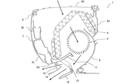
図1は、本発明の実施の形態1に係る空気調和機の室内機の、分解斜視図である。図2は、本発明の実施の形態1に係る空気調和機の室内機の、断面図である。
図1及び図2に示されるように、室内機1は、筐体2と、送風機3と、熱交換器4と、フィルターユニット5と、電気品箱6と、ドレンパン組立体7と、を備える。
1 is an exploded perspective view of an indoor unit of an air conditioner according to
As shown in FIGS. 1 and 2, the
筐体2は、例えば、室内の壁面等に取り付けられる基台2aと、基台2aの前方に配設される枠体2bと、枠体2bの前方に配設される前面パネル2cと、を有する。筐体2の、例えば、上面に、吸込口2dが形成され、前面下部に、吹出口2eが形成される。基台2aの前面下部に、吸込口2dと吹出口2eとの間の風路の一部を構成し、吹出口2eに向かって延びるリアガイド8が配設される。
The
送風機3は、例えば、貫流ファンであり、筐体2の内側の、吸込口2dと吹出口2eとの間の風路に、回転軸が室内機1の左右方向と平行になるように配設され、吸込口2dから室内空気を吸い込んで、吹出口2eから吹き出す。
The
熱交換器4は、例えば、フィンチューブ型であり、筐体2の内側の、吸込口2dと吹出口2eとの間の風路に、送風機3の前方及び上方を覆うように配設される。熱交換器4には、冷媒が供給される。
The heat exchanger 4 is, for example, a fin tube type, and is disposed in an air path between the
フィルターユニット5は、例えば、吸込口2dに配設される。なお、フィルターユニット5は、自動清掃機能を有してもよく、また、有しなくてもよい。
The
電気品箱6は、例えば、筐体2の内側に配設され、室内機1の制御を司る制御装置6a等が収納される。制御装置6aは、例えば、マイクロプロセッサユニット等で構成される。制御装置6aは、そのようなものに限定されず、例えば、ファームウェア等の更新可能なもので構成されてもよく、また、CPU等からの指令によって実行されるプログラムモジュール等であってもよい。
The
ドレンパン組立体7は、例えば、筐体2の内側の、前方下部に配設される。ドレンパン組立体7は、ノズル部11と、上側支持部12と、下側支持部13と、上側上下方向風向調整板14と、下側上下方向風向調整板15と、を有する。なお、ドレンパン組立体7が、左右方向風向調整板を有してもよく、また、有しなくてもよい。下側上下方向風向調整板15の構成は、後に詳述される。
The
ノズル部11の先端は、送風機3の近傍まで延び、ノズル部11の先端とリアガイド8との間に、送風機3が配設される。ノズル部11の上面は、熱交換器4の結露水を受けるドレンパンとして機能すると共に、吸込口2dと送風機3との間の風路の一部を構成し、ノズル部11の下面は、送風機3と吹出口2eとの間の風路の一部を構成する。
The tip of the
上側支持部12は、ノズル部11の下面に配設され、上側上下方向風向調整板14を支持する。また、下側支持部13は、ノズル部11の下面に配設され、下側上下方向風向調整板15を支持する。
The
図3は、本発明の実施の形態1に係る空気調和機の室内機の、ドレンパン組立体の斜視図である。なお、図3(a)は、上側上下方向風向調整板14及び下側上下方向風向調整板15が取り付けられた状態での斜視図であり、図3(b)は、上側上下方向風向調整板14及び下側上下方向風向調整板15が取り外された状態での斜視図である。また、図3は、ドレンパン組立体7が、左右方向風向調整板を有する場合を示している。
FIG. 3 is a perspective view of the drain pan assembly of the indoor unit of the air conditioner according to
図3に示されるように、ドレンパン組立体7は、室内機1の左右方向に並置された2つの下側上下方向風向調整板15_1、15_2を、下側支持部13によって支持する。下側支持部13は、例えば、下側外側支持部13a_1、13a_2と、下側中央側支持部13b_1、13b_2と、で構成される。
As shown in FIG. 3, the
下側外側支持部13a_1、13a_2は、室内機1の左右方向の外側に配設され、下側上下方向風向調整板15_1、15_2の、室内機1の左右方向の外側の端部を支持する。
The lower outer support portions 13a_1 and 13a_2 are disposed on the outer side in the left-right direction of the
下側中央側支持部13b_1、13b_2は、室内機1の左右方向の中央側に形成され、下側上下方向風向調整板15_1、15_2の、室内機1の左右方向の中央側の端部を支持する。下側中央側支持部13b_1及び下側中央側支持部13b_2が、一体化されるとよい。
The lower center side support portions 13b_1 and 13b_2 are formed on the center side in the left-right direction of the
図4は、本発明の実施の形態1に係る空気調和機の室内機の、ドレンパン組立体の下側外側支持部の支持構造を説明する図である。なお、図4では、下側上下方向風向調整板15_1の支持構造を示しているが、下側上下方向風向調整板15_2の支持構造についても同様である。
FIG. 4 is a diagram illustrating a support structure for the lower outer support portion of the drain pan assembly of the indoor unit for an air conditioner according to
図4に示されるように、下側外側支持部13a_1、13a_2は、例えば、ステッピングモーター等の回動機構21を内蔵する。下側上下方向風向調整板15_1、15_2には、例えば、十字状の穴31aが形成された連結部31が配設される。回動機構21の出力軸21aは、連結部材22を介して、穴31aに連結される。回動機構21の出力軸21aの回転角度が、制御装置6aによって制御されることで、下側上下方向風向調整板15_1、15_2の上下方向の角度が調整される。
As shown in FIG. 4, the lower outer support portions 13a_1 and 13a_2 incorporate a
図5は、本発明の実施の形態1に係る空気調和機の室内機の、ドレンパン組立体の下側中央支持部の支持構造を説明する図である。なお、図5では、下側上下方向風向調整板15_1の支持構造を示しているが、下側上下方向風向調整板15_2の支持構造についても同様である。
FIG. 5 is a diagram illustrating a support structure of the lower center support portion of the drain pan assembly of the indoor unit for an air conditioner according to
図5に示されるように、下側中央側支持部13b_1、13b_2には、室内機1の左右方向に貫通する穴13baが形成される。下側上下方向風向調整板15_1、15_2には、軸部材32aを有する連結部32が配設される。軸部材32aは、図中矢印方向にスライドすることができる。使用者、保守作業者等によって、軸部材32aが図中実線矢印方向にスライドされると、軸部材32aの先端が、穴13baに挿入されて、下側上下方向風向調整板15_1、15_2が、下側支持部13に支持される。使用者、保守作業者等によって、軸部材32aが図中点線矢印方向にスライドされると、下側上下方向風向調整板15_1、15_2が、下側支持部13から離脱される。そのように構成されることで、使用者、保守作業者等が、下側上下方向風向調整板15_1、15_2を取り外して、清掃することが可能となる。
As shown in FIG. 5, a hole 13ba penetrating in the left-right direction of the
以下に、空気調和機の室内機1の気流について説明する。
図6は、本発明の実施の形態1に係る空気調和機の室内機の、気流を説明する図である。なお、図6は、室内機1が、冷房運転時の水平吹きを行っている状態を示している。
Below, the airflow of the
FIG. 6 is a diagram illustrating airflow of the indoor unit of the air conditioner according to
図6に示されるように、吸込口2dから吸い込まれた室内空気は、熱交換器4を通過することで冷却又は加熱され、リアガイド8とノズル部11の下面との間を通った後、吹出口2eから、上側上下方向風向調整板14及び下側上下方向風向調整板15の角度に応じた方向に吹き出される。
As shown in FIG. 6, the indoor air sucked from the
室内機1では、上下方向風向調整板が、上側上下方向風向調整板14と下側上下方向風向調整板15とで構成されるため、上側上下方向風向調整板14及び下側上下方向風向調整板15を、上側上下方向風向調整板14の下面と下側上下方向風向調整板15の上面との間隔が気流の下流側ほど狭くなるような角度に調整して、冷却空気又は加熱空気を遠くまで吹き出すことが可能である。
In the
また、室内機1では、下側上下方向風向調整板15が、リアガイド8の延長面上、つまり、吸込口2dと吹出口2eとの間の風路の下面の延長面上にあるため、冷房運転時の水平吹きを行う際にも、上側上下方向風向調整板14の下面と下側上下方向風向調整板15の上面との間に多くの冷却空気を導くことができる。
Further, in the
つまり、室内機1では、冷房運転時の水平吹きを行う際の冷却性能を向上するために、下側上下方向風向調整板15が、その下面の少なくとも一部が、冷房運転時に、吸込口2dと吹出口2eとの間の風路の延長面の下側に位置するように、下側支持部13によって支持されている。
That is, in the
しかし、そのような構成を採用すると、冷房運転時の水平吹きにおいて、冷却空気が、下側上下方向風向調整板15の下面側を殆ど通過せず、下側上下方向風向調整板15の上面が、冷却空気によって冷却された状態で、下側上下方向風向調整板15の下面が、室内空気に接触することとなって、下側上下方向風向調整板15の下面に結露が生じることとなる。
However, if such a configuration is adopted, in horizontal blowing during cooling operation, the cooling air hardly passes the lower surface side of the lower vertical air
そのため、下側上下方向風向調整板15は、中空状であり、中空部の内側に断熱層として機能する空気層が形成される。なお、上側上下方向風向調整板14は、冷房運転時の水平吹きにおいて、冷却空気が、その上面側及び下面側を通過し、結露が生じ難いため、中空状としていないが、中空状であってもよい。また、上側上下方向風向調整板14が、冷房運転時の水平吹きにおいて、その上面側を冷却空気が殆ど通過しない位置に、支持されてもよい。
Therefore, the lower vertical air
また、下側上下方向風向調整板15が、中空状であり、中空部の内側に断熱層として機能する空気層が形成されていても、下側上下方向風向調整板15の気流の下流側の先端が太い場合には、その先端の気流の下流側で、室内空気の巻き込みが生じて、その先端に結露が生じることとなる。
Further, even if the lower vertical air
そのため、下側上下方向風向調整板15は、気流の下流側の先端に生じる結露を抑制するために、その先端が細くされる。
Therefore, the tip of the lower vertical air
従来の空気調和機の室内機では、上下方向風向調整板の先端を細くして、且つ、その先端を中空状にしようとすると、成型上又は加工上の困難性が増してしまうため、構造上、下側上下方向風向調整板15の先端に生じる結露の抑制と、その先端の周囲の表面に生じる結露の抑制と、を両立することができなかった。
In a conventional air conditioner indoor unit, if the tip of the vertical air direction adjusting plate is made thin and the tip is made hollow, the difficulty in molding or processing increases. In addition, it was impossible to achieve both suppression of dew condensation occurring at the tip of the lower vertical air
それに対し、室内機1では、以下のような構成の下側上下方向風向調整板15を採用しているため、上下方向風向調整板の先端を細くして、且つ、その先端を中空状にすることを、成型上又は加工上の困難性を増すことなく実現できるため、下側上下方向風向調整板15の先端に生じる結露の抑制と、その先端の周囲の表面に生じる結露の抑制と、を両立することが可能である。
On the other hand, since the
(下側上下方向風向調整板の構成)
以下に、実施の形態1に係る空気調和機の室内機の、下側上下方向風向調整板の構成について説明する。
(Configuration of lower vertical wind direction adjustment plate)
Below, the structure of the lower up-down direction wind direction adjusting plate of the indoor unit of the air conditioner according to
図7は、本発明の実施の形態1に係る空気調和機の室内機の、下側上下方向風向調整板の分解斜視図である。なお、図7では、下側上下方向風向調整板15_1の分解斜視図を示しているが、下側上下方向風向調整板15_2の分解斜視図についても同様である。
FIG. 7 is an exploded perspective view of the lower vertical air direction adjusting plate of the indoor unit of the air conditioner according to
図7に示されるように、下側上下方向風向調整板15は、ベース板41と、カバー板42と、を有する。ベース板41及びカバー板42は、例えば、樹脂製であり、射出成型等によって成型される。ベース板41とカバー板42とは、互いの裏面が対向するように、例えば、超音波接合等によって、接合される。
As shown in FIG. 7, the lower vertical air
ベース板41は、カバー板42が接合される第1領域51と、カバー板42が接合されず、第1領域51の外側に延出し、室内機1の左右方向の外側に位置する外側第2領域52aと、カバー板42が接合されず、第1領域51の外側に延出し、室内機1の左右方向の中央側に位置する中央側第2領域52bと、を有する。なお、以下では、外側第2領域52aと中央側第2領域52bとを総称して、第2領域52と記載する場合がある。
The
第2領域52は、第1領域51の気流の上流側に位置する。外側第2領域52aには、連結部31が配設される。中央側第2領域52bには、連結部32が配設される。
The second region 52 is located on the upstream side of the air flow in the
図8は、本発明の実施の形態1に係る空気調和機の室内機の、ベース板の第2領域の周辺の斜視図である。図9は、本発明の実施の形態1に係る空気調和機の室内機の、ベース板の断面図である。なお、図9(a)は、図7におけるA−A線での断面図であり、図9(b)は、図7におけるB−B線での断面図である。また、図8及び図9(b)では、外側第2領域52aの周辺の斜視図及び断面図を示しているが、中央側第2領域52bの周辺の斜視図及び断面図についても同様である。
FIG. 8 is a perspective view of the periphery of the second region of the base plate of the indoor unit for an air conditioner according to
図8及び図9に示されるように、第1領域51の裏面の、気流の上流側の壁面61の上面には、段差62が形成される。第1領域51の裏面の、第2領域52と隣接しない領域の周縁には、リブ63が形成される。
As shown in FIGS. 8 and 9, a
第2領域52は、袋部71を有する。つまり、第2領域52は、袋状に成形される。袋部71は、第1領域51の裏面から延びる壁面72と、壁面72と対向する壁面73と、壁面72と壁面73との間の三方向を閉塞する側壁面74、75、76と、によって囲まれ、壁面72と壁面73との間の一方向が開口部77となるような空間を形成する。外側第2領域52aの袋部71と、中央側第2領域52bの袋部71と、は互いの開口部77が対向する向きに形成される。つまり、袋部71は、開口部77が下側上下方向風向調整板15の左右方向の中央側を向くように形成される。壁面73に、下側上下方向風向調整板15の脱着の際の注意事項等が、表記されてもよい。
The second region 52 has a
第2領域52の、袋部71の壁面73の第1領域51と隣接する領域の周縁には、段差62から延びる段差78が形成される。つまり、第2領域52の、カバー板42の第1領域51と対向する面の裏側の面(表面)と並ぶ面に、段差78が形成される。
A
連結部31及び連結部32は、剛性の観点で、側壁面74、75、76の上方に配設される。また、室内機1が、運転停止時に、上側上下方向風向調整板14及び下側上下方向風向調整板15によって、吹出口2eを塞ぐように制御される場合には、連結部31及び連結部32は、第2領域52の、運転停止時の外観面とならない側の壁面(壁面73)に配設される。そのように構成されることで、連結部31及び連結部32が、ベース板41と一体で成型され、剛性の観点からサイズを大きく又は肉厚を厚くされるような場合でも、運転停止時の外観面にひけが生じることが抑制される。
The
図10は、本発明の実施の形態1に係る空気調和機の室内機の、カバー板の斜視図である。
図10に示されるように、カバー板42の裏面には、周縁から所定の間隔を有する位置に、全周に亘ってリブ81が形成される。リブ81の先端は、尖っているとよい。
FIG. 10 is a perspective view of the cover plate of the indoor unit for an air conditioner according to
As shown in FIG. 10, on the back surface of the
図11は、本発明の実施の形態1に係る空気調和機の室内機の、下側上下方向風向調整板の、ベース板にカバー板が接合された状態での断面図である。なお、図11(a)は、図7におけるA−A線での断面図であり、図11(b)は、図11(a)におけるD部の拡大図であり、図11(c)は、図11(a)におけるE部の拡大図であり、図11(d)は、図7におけるC−C線での外側第2領域52aの周辺の断面図である。また、図11(d)では、外側第2領域52aの周辺の断面図を示しているが、中央側第2領域52bの周辺の断面図についても同様である。
FIG. 11 is a cross-sectional view of the indoor unit of the air conditioner according to
図11(a)〜(c)に示されるように、ベース板41とカバー板42とが、カバー板42の周縁が、ベース板41の第1領域51の段差62の外壁面及びリブ63の内側に位置するように、位置決めされる。つまり、ベース板41に段差62及びリブ63が形成されているため、ベース板41とカバー板42との位置決めの作業性及び正確性が向上される。そして、その際に、カバー板42の裏面に形成されたリブ81の先端が、ベース板41の第1領域51の裏面に当接する。
As shown in FIGS. 11A to 11C, the
その状態で、ベース板41とカバー板42とが近づくように押圧され、超音波振動が加えられると、リブ81の先端とベース板41の第1領域51の裏面とが摩擦熱で溶けて接合される。リブ81が、カバー板42の裏面に全周に亘って形成されているため、ベース板41とカバー板42との間に、密閉された中空部43が形成されることとなる。
In this state, when the
また、図11(d)に示されるように、ベース板41の第2領域52の段差78が、カバー板42のリブ81が形成される領域の外側の領域を受けるため、袋部71の開口部77が塞がれて、中空部44が形成されることとなる。第2領域52は、連結部31及び連結部32が配設されているため、超音波振動を加えるためのホーンを当て難いが、中空部44が、超音波接合によらずに塞がれるため、接合の作業性が向上される。
Further, as shown in FIG. 11D, since the
袋部71が、三方向に側壁面74、75、76を有しているため、つまり、第2領域52に側壁面74が形成されているため、超音波接合時に、カバー板42のリブ81が形成される領域の外側の領域が、段差78に押し付けられることによって、段差78の面が撓んで、隙間が生じることが抑制される。また、下側上下方向風向調整板15が、下側支持部13によって支持された時に、段差78の面が撓んで、隙間が生じることが抑制される。そのため、中空部44は、ほぼ密閉された中空部となる。
Since the
<空気調和機の室内機の作用>
以下に、実施の形態1に係る空気調和機の室内機の作用について説明する。
下側上下方向風向調整板15が、ベース板41とカバー板42とを有し、袋部71によって形成される中空部44の気流の下流側に、ベース板41とカバー板42との接合によって形成される中空部43が位置する。ベース板41とカバー板42との接合によって形成される中空部43の厚みを薄くする場合には、ベース板41とカバー板42との間隔を狭めればよく、ベース板41及びカバー板42の厚み自体を薄くする必要がない。そのため、下側上下方向風向調整板15の気流の下流側の先端を細くしつつ、その先端を中空状にすることを、成型上又は加工上の困難性が増えることのない第1領域51の中空部43の厚みを薄くすることによって実現でき、上下方向風向調整板の先端に生じる結露の抑制と、その先端の周囲の表面に生じる結露の抑制と、を両立することができる。
<Operation of air conditioner indoor unit>
Below, the effect | action of the indoor unit of the air conditioner which concerns on
The lower vertical air
特に、下側上下方向風向調整板15が、その下面の少なくとも一部が、冷房運転時に、吸込口2dと吹出口2eとの間の風路の延長面の下側に位置するように、下側支持部13によって支持されている場合においても、上下方向風向調整板の先端に生じる結露の抑制と、その先端の周囲の表面に生じる結露の抑制と、を両立することができる。
In particular, the lower vertical air
実施の形態2.
実施の形態2に係る空気調和機の室内機について説明する。
なお、以下では、実施の形態1と重複又は類似する説明については、適宜簡略化又は省略している。
An indoor unit of an air conditioner according to
Note that, in the following, descriptions that overlap or are similar to those of the first embodiment are appropriately simplified or omitted.
<空気調和機の室内機の構成>
以下に、実施の形態2に係る空気調和機の室内機の構成について説明する。
<Configuration of indoor unit of air conditioner>
Below, the structure of the indoor unit of the air conditioner which concerns on
(下側上下方向風向調整板の構成)
以下に、実施の形態2に係る空気調和機の室内機の、下側上下方向風向調整板の構成について説明する。
(Configuration of lower vertical wind direction adjustment plate)
Below, the structure of the lower up-down direction wind direction adjusting plate of the indoor unit of the air conditioner according to
図12は、本発明の実施の形態2に係る空気調和機の室内機の、下側上下方向風向調整板の、ベース板にカバー板が接合された状態での断面図である。なお、図12は、図7におけるC−C線での外側第2領域52aの周辺の断面図である。また、図12では、外側第2領域52aの周辺の断面図を示しているが、中央側第2領域52bの周辺の断面図についても同様である。
FIG. 12 is a cross-sectional view of the lower vertical air direction adjusting plate of the indoor unit for an air conditioner according to
図12に示されるように、中空部44の全て又は一部に、断熱材45が配設される。
As shown in FIG. 12, a
<空気調和機の室内機の作用>
以下に、実施の形態2に係る空気調和機の室内機の作用について説明する。
中空部44は、袋部71の開口部77がカバー板42によって塞がれることで形成されるが、第2領域52の剛性の不足によって、カバー板42のリブ81が形成される領域の外側の領域と段差78との間に隙間が生じる場合があり、そのような場合には、断熱性能が低下してしまう。下側上下方向風向調整板15では、中空部44の全て又は一部に、断熱材45が配設されるため、そのような場合でも、断熱性能が低下することが抑制され、第2領域52の表面に生じる結露の抑制が確実化される。
<Operation of air conditioner indoor unit>
Below, the effect | action of the indoor unit of the air conditioner which concerns on
The
なお、実施の形態1に係る空気調和機の室内機では、カバー板42の裏面に全周に亘って形成されるリブ81によって、ベース板41とカバー板42との間に、密閉された中空部43が形成されるが、リブ81が断続的に形成されていてもよく、そのような場合には、中空部43の密閉性が不足する場合がある。そのような場合においても、中空部44と同様に、中空部43の全て又は一部に、断熱材45が配設されるとよい。
In the indoor unit of the air conditioner according to the first embodiment, a hollow sealed between the
以上、実施の形態1及び実施の形態2について説明したが、本発明は各実施の形態の説明に限定されない。例えば、各実施の形態の全て又は一部を組み合わせることも可能である。
As mentioned above, although
1 室内機、2 筐体、2a 基台、2b 枠体、2c 前面パネル、2d 吸込口、2e 吹出口、3 送風機、4 熱交換器、5 フィルターユニット、6 電気品箱、6a 制御装置、7 ドレンパン組立体、8 リアガイド、11 ノズル部、12 上側支持部、13 下側支持部、13a_1、13a_2 下側外側支持部、13b_1、13b_2 下側中央側支持部、13ba 穴、14 上側上下方向風向調整板、15、15_1、15_2 下側上下方向風向調整板、21 回動機構、21a 出力軸、22 連結部材、31 連結部、31a 穴、32 連結部、32a 軸部材、41 ベース板、42 カバー板、43 中空部、44 中空部、45 断熱材、51 第1領域、52 第2領域、52a 外側第2領域、52b 中央側第2領域、61 壁面、62 段差、63 リブ、71 袋部、72、73 壁面、74〜76 側壁面、77 開口部、78 段差、81 リブ。
DESCRIPTION OF
Claims (7)
前記筐体の内側に配設され、前記吸込口から空気を吸い込んで、前記吹出口から吹き出す送風機と、
前記筐体の内側の、前記吸込口と前記吹出口との間の風路に配設された熱交換器と、
前記吹出口から吹き出される気流の上下方向の風向を調整する上下方向風向調整板と、を備え、
前記上下方向風向調整板は、ベース板とカバー板とを有し、
前記ベース板は、前記カバー板が中空部を形成するように接合された第1領域と、該第1領域の外側に形成され、袋状に成形された第2領域と、を有し、
前記第2領域は、前記第1領域の前記気流の上流側に形成された、
ことを特徴とする空気調和機の室内機。 A housing in which an inlet and an outlet are formed;
A blower that is disposed inside the housing, sucks air from the suction port, and blows out from the blowout port;
A heat exchanger disposed in an air path between the suction port and the air outlet, inside the housing;
An up-down direction air direction adjusting plate that adjusts the up-down direction air direction of the air flow blown from the air outlet,
The vertical air direction adjustment plate has a base plate and a cover plate,
The base plate has a first region joined so that the cover plate forms a hollow portion, and a second region formed outside the first region and shaped like a bag,
The second region is formed on the upstream side of the airflow of the first region,
An air conditioner indoor unit.
ことを特徴とする請求項1に記載の空気調和機の室内機。 On the surface of the cover plate facing the first region, a rib whose tip abuts on the first region is formed.
The indoor unit of the air conditioner according to claim 1.
ことを特徴とする請求項2に記載の空気調和機の室内機。 The rib is formed over the entire circumference of the cover plate,
The indoor unit of the air conditioner according to claim 2, wherein the indoor unit is an air conditioner.
ことを特徴とする請求項2又は3に記載の空気調和機の室内機。 On the base plate, a step is formed to receive a region where the rib is not formed on the surface of the cover plate facing the first region.
The indoor unit of an air conditioner according to claim 2 or 3,
ことを特徴とする請求項1〜4のいずれか一項に記載の空気調和機の室内機。 The cover plate has engaged ultrasonic Namise' to the first region,
The indoor unit of the air conditioner as described in any one of Claims 1-4 characterized by the above-mentioned.
ことを特徴とする請求項1〜5のいずれか一項に記載の空気調和機の室内機。 A heat insulating material is disposed in the bag portion of the second region,
The indoor unit of an air conditioner according to any one of claims 1 to 5, wherein the indoor unit is an air conditioner.
ことを特徴とする請求項1〜6のいずれか一項に記載の空気調和機の室内機。 The vertical direction air direction adjusting plate is located at the lower side of the extended surface of the air path at least part of the lower surface during cooling operation.
The indoor unit of an air conditioner according to any one of claims 1 to 6, wherein the indoor unit is an air conditioner.
Priority Applications (2)
| Application Number | Priority Date | Filing Date | Title |
|---|---|---|---|
| JP2013161339A JP5963719B2 (en) | 2013-08-02 | 2013-08-02 | Air conditioner indoor unit |
| CN201420426570.2U CN204026846U (en) | 2013-08-02 | 2014-07-30 | The indoor set of air conditioner |
Applications Claiming Priority (1)
| Application Number | Priority Date | Filing Date | Title |
|---|---|---|---|
| JP2013161339A JP5963719B2 (en) | 2013-08-02 | 2013-08-02 | Air conditioner indoor unit |
Publications (3)
| Publication Number | Publication Date |
|---|---|
| JP2015031454A JP2015031454A (en) | 2015-02-16 |
| JP2015031454A5 JP2015031454A5 (en) | 2015-07-30 |
| JP5963719B2 true JP5963719B2 (en) | 2016-08-03 |
Family
ID=52066696
Family Applications (1)
| Application Number | Title | Priority Date | Filing Date |
|---|---|---|---|
| JP2013161339A Active JP5963719B2 (en) | 2013-08-02 | 2013-08-02 | Air conditioner indoor unit |
Country Status (2)
| Country | Link |
|---|---|
| JP (1) | JP5963719B2 (en) |
| CN (1) | CN204026846U (en) |
Families Citing this family (4)
| Publication number | Priority date | Publication date | Assignee | Title |
|---|---|---|---|---|
| WO2018029828A1 (en) * | 2016-08-10 | 2018-02-15 | 三菱電機株式会社 | Indoor unit of air-conditioner |
| JP2018091507A (en) * | 2016-11-30 | 2018-06-14 | 三菱重工サーマルシステムズ株式会社 | Indoor unit for air conditioner |
| US11906195B2 (en) | 2018-05-16 | 2024-02-20 | Mitsubishi Electric Corporation | Indoor unit of air-conditioning apparatus and air-conditioning apparatus |
| AU2019448451B2 (en) | 2019-05-30 | 2023-01-12 | Mitsubishi Electric Corporation | Indoor unit of air-conditioning apparatus |
Family Cites Families (7)
| Publication number | Priority date | Publication date | Assignee | Title |
|---|---|---|---|---|
| US4469132A (en) * | 1982-06-28 | 1984-09-04 | Mcquay Inc. | Damper apparatus |
| JP3118543B2 (en) * | 1994-08-22 | 2000-12-18 | ダイキン工業株式会社 | Air conditioner makeup panel |
| JP3885845B2 (en) * | 1998-03-16 | 2007-02-28 | 株式会社富士通ゼネラル | Air conditioner |
| JP4141369B2 (en) * | 2003-10-17 | 2008-08-27 | シャープ株式会社 | Wind direction plate and air conditioner |
| JP2008281303A (en) * | 2007-05-14 | 2008-11-20 | Panasonic Corp | Air conditioner |
| JP2009014289A (en) * | 2007-07-06 | 2009-01-22 | Panasonic Corp | Air conditioner |
| JP5211865B2 (en) * | 2008-06-05 | 2013-06-12 | ダイキン工業株式会社 | Air-conditioning indoor unit movable panel |
-
2013
- 2013-08-02 JP JP2013161339A patent/JP5963719B2/en active Active
-
2014
- 2014-07-30 CN CN201420426570.2U patent/CN204026846U/en not_active Expired - Fee Related
Also Published As
| Publication number | Publication date |
|---|---|
| CN204026846U (en) | 2014-12-17 |
| JP2015031454A (en) | 2015-02-16 |
Similar Documents
| Publication | Publication Date | Title |
|---|---|---|
| US6338676B1 (en) | Air conditioner | |
| JP5963719B2 (en) | Air conditioner indoor unit | |
| CN106016453B (en) | Ceiling embedded air conditioner | |
| CN106403232B (en) | Ceiling embedded air conditioner | |
| JP6559255B2 (en) | Air conditioner indoor unit | |
| JP2008032238A (en) | Air-conditioner | |
| WO2019229879A1 (en) | Indoor unit of air conditioner | |
| JP6091386B2 (en) | Blower and refrigeration cycle apparatus | |
| JP5071573B2 (en) | Air conditioner | |
| JP6758992B2 (en) | Indoor unit and air conditioner | |
| JP2010071170A (en) | Centrifugal blower | |
| JP2007322103A (en) | Air conditioner | |
| JP2001124360A (en) | Centrifugal blower and air conditioner | |
| JP5961751B2 (en) | Air conditioner | |
| JP2019020079A (en) | Flap, and wall type room air conditioner indoor unit provided with the same | |
| JP5724924B2 (en) | Indoor unit | |
| WO2019187038A1 (en) | Indoor unit for air conditioner | |
| JP2016044874A (en) | Feather parts | |
| JP2016191492A (en) | Embedded ceiling air conditioner | |
| JP4835115B2 (en) | Electrical component assembly and outdoor unit of air conditioner including the same | |
| JP5071599B2 (en) | Air conditioner | |
| JP2007040617A (en) | Air conditioning indoor unit | |
| JPWO2018189894A1 (en) | Air conditioner indoor unit | |
| AU743130B2 (en) | Air conditioner | |
| JP2014145508A (en) | Air conditioner |
Legal Events
| Date | Code | Title | Description |
|---|---|---|---|
| A521 | Request for written amendment filed |
Free format text: JAPANESE INTERMEDIATE CODE: A523 Effective date: 20150611 |
|
| A621 | Written request for application examination |
Free format text: JAPANESE INTERMEDIATE CODE: A621 Effective date: 20150611 |
|
| A977 | Report on retrieval |
Free format text: JAPANESE INTERMEDIATE CODE: A971007 Effective date: 20151013 |
|
| A131 | Notification of reasons for refusal |
Free format text: JAPANESE INTERMEDIATE CODE: A131 Effective date: 20151110 |
|
| A521 | Request for written amendment filed |
Free format text: JAPANESE INTERMEDIATE CODE: A523 Effective date: 20151224 |
|
| TRDD | Decision of grant or rejection written | ||
| A01 | Written decision to grant a patent or to grant a registration (utility model) |
Free format text: JAPANESE INTERMEDIATE CODE: A01 Effective date: 20160531 |
|
| A61 | First payment of annual fees (during grant procedure) |
Free format text: JAPANESE INTERMEDIATE CODE: A61 Effective date: 20160628 |
|
| R150 | Certificate of patent or registration of utility model |
Ref document number: 5963719 Country of ref document: JP Free format text: JAPANESE INTERMEDIATE CODE: R150 |
|
| R250 | Receipt of annual fees |
Free format text: JAPANESE INTERMEDIATE CODE: R250 |
|
| R250 | Receipt of annual fees |
Free format text: JAPANESE INTERMEDIATE CODE: R250 |
|
| R250 | Receipt of annual fees |
Free format text: JAPANESE INTERMEDIATE CODE: R250 |
|
| R250 | Receipt of annual fees |
Free format text: JAPANESE INTERMEDIATE CODE: R250 |
|
| R250 | Receipt of annual fees |
Free format text: JAPANESE INTERMEDIATE CODE: R250 |
|
| R250 | Receipt of annual fees |
Free format text: JAPANESE INTERMEDIATE CODE: R250 |