JP5962596B2 - Ejector refrigeration cycle - Google Patents
Ejector refrigeration cycle Download PDFInfo
- Publication number
- JP5962596B2 JP5962596B2 JP2013127580A JP2013127580A JP5962596B2 JP 5962596 B2 JP5962596 B2 JP 5962596B2 JP 2013127580 A JP2013127580 A JP 2013127580A JP 2013127580 A JP2013127580 A JP 2013127580A JP 5962596 B2 JP5962596 B2 JP 5962596B2
- Authority
- JP
- Japan
- Prior art keywords
- refrigerant
- ejector
- refrigeration cycle
- evaporator
- nozzle
- Prior art date
- Legal status (The legal status is an assumption and is not a legal conclusion. Google has not performed a legal analysis and makes no representation as to the accuracy of the status listed.)
- Active
Links
- 238000005057 refrigeration Methods 0.000 title claims description 94
- 239000003507 refrigerant Substances 0.000 claims description 689
- 239000012071 phase Substances 0.000 claims description 104
- 239000007788 liquid Substances 0.000 claims description 83
- 238000002347 injection Methods 0.000 claims description 76
- 239000007924 injection Substances 0.000 claims description 76
- 239000002826 coolant Substances 0.000 claims description 36
- 239000007791 liquid phase Substances 0.000 claims description 26
- 238000003860 storage Methods 0.000 claims description 22
- 238000001704 evaporation Methods 0.000 claims description 21
- 230000009471 action Effects 0.000 claims description 16
- 230000007423 decrease Effects 0.000 claims description 12
- 230000006837 decompression Effects 0.000 claims description 11
- 230000007246 mechanism Effects 0.000 claims description 10
- 230000008859 change Effects 0.000 claims description 7
- 230000002051 biphasic effect Effects 0.000 claims description 6
- 230000004323 axial length Effects 0.000 claims description 3
- 238000007599 discharging Methods 0.000 claims 1
- 230000035939 shock Effects 0.000 description 24
- 239000007789 gas Substances 0.000 description 20
- 238000010586 diagram Methods 0.000 description 18
- 230000000694 effects Effects 0.000 description 16
- 230000008020 evaporation Effects 0.000 description 16
- 238000009833 condensation Methods 0.000 description 15
- 230000005494 condensation Effects 0.000 description 15
- 230000006835 compression Effects 0.000 description 9
- 238000007906 compression Methods 0.000 description 9
- 230000002093 peripheral effect Effects 0.000 description 9
- 239000012530 fluid Substances 0.000 description 8
- 230000006872 improvement Effects 0.000 description 8
- 229920006395 saturated elastomer Polymers 0.000 description 6
- 238000011144 upstream manufacturing Methods 0.000 description 6
- 238000007664 blowing Methods 0.000 description 5
- 238000001816 cooling Methods 0.000 description 5
- 238000006243 chemical reaction Methods 0.000 description 4
- 229910052751 metal Inorganic materials 0.000 description 4
- 239000002184 metal Substances 0.000 description 4
- 230000004048 modification Effects 0.000 description 3
- 238000012986 modification Methods 0.000 description 3
- 239000002245 particle Substances 0.000 description 3
- 239000011347 resin Substances 0.000 description 3
- 229920005989 resin Polymers 0.000 description 3
- 238000009423 ventilation Methods 0.000 description 3
- 238000004378 air conditioning Methods 0.000 description 2
- 230000037237 body shape Effects 0.000 description 2
- 230000003247 decreasing effect Effects 0.000 description 2
- 239000007792 gaseous phase Substances 0.000 description 2
- 238000000034 method Methods 0.000 description 2
- 230000008569 process Effects 0.000 description 2
- 230000005855 radiation Effects 0.000 description 2
- 230000009467 reduction Effects 0.000 description 2
- 230000007480 spreading Effects 0.000 description 2
- 238000003892 spreading Methods 0.000 description 2
- 238000004781 supercooling Methods 0.000 description 2
- 239000011800 void material Substances 0.000 description 2
- 238000005411 Van der Waals force Methods 0.000 description 1
- 238000010521 absorption reaction Methods 0.000 description 1
- 239000000956 alloy Substances 0.000 description 1
- 229910045601 alloy Inorganic materials 0.000 description 1
- 229910052782 aluminium Inorganic materials 0.000 description 1
- XAGFODPZIPBFFR-UHFFFAOYSA-N aluminium Chemical compound [Al] XAGFODPZIPBFFR-UHFFFAOYSA-N 0.000 description 1
- 238000009835 boiling Methods 0.000 description 1
- 238000004364 calculation method Methods 0.000 description 1
- 238000001514 detection method Methods 0.000 description 1
- 230000006866 deterioration Effects 0.000 description 1
- 238000006073 displacement reaction Methods 0.000 description 1
- 239000003651 drinking water Substances 0.000 description 1
- 235000020188 drinking water Nutrition 0.000 description 1
- 230000005484 gravity Effects 0.000 description 1
- 238000005304 joining Methods 0.000 description 1
- 230000001050 lubricating effect Effects 0.000 description 1
- 239000000463 material Substances 0.000 description 1
- 230000000737 periodic effect Effects 0.000 description 1
- 238000005507 spraying Methods 0.000 description 1
- 239000012808 vapor phase Substances 0.000 description 1
- XLYOFNOQVPJJNP-UHFFFAOYSA-N water Substances O XLYOFNOQVPJJNP-UHFFFAOYSA-N 0.000 description 1
Images


Classifications
-
- F—MECHANICAL ENGINEERING; LIGHTING; HEATING; WEAPONS; BLASTING
- F04—POSITIVE - DISPLACEMENT MACHINES FOR LIQUIDS; PUMPS FOR LIQUIDS OR ELASTIC FLUIDS
- F04F—PUMPING OF FLUID BY DIRECT CONTACT OF ANOTHER FLUID OR BY USING INERTIA OF FLUID TO BE PUMPED; SIPHONS
- F04F5/00—Jet pumps, i.e. devices in which flow is induced by pressure drop caused by velocity of another fluid flow
- F04F5/14—Jet pumps, i.e. devices in which flow is induced by pressure drop caused by velocity of another fluid flow the inducing fluid being elastic fluid
- F04F5/16—Jet pumps, i.e. devices in which flow is induced by pressure drop caused by velocity of another fluid flow the inducing fluid being elastic fluid displacing elastic fluids
- F04F5/20—Jet pumps, i.e. devices in which flow is induced by pressure drop caused by velocity of another fluid flow the inducing fluid being elastic fluid displacing elastic fluids for evacuating
-
- F—MECHANICAL ENGINEERING; LIGHTING; HEATING; WEAPONS; BLASTING
- F25—REFRIGERATION OR COOLING; COMBINED HEATING AND REFRIGERATION SYSTEMS; HEAT PUMP SYSTEMS; MANUFACTURE OR STORAGE OF ICE; LIQUEFACTION SOLIDIFICATION OF GASES
- F25B—REFRIGERATION MACHINES, PLANTS OR SYSTEMS; COMBINED HEATING AND REFRIGERATION SYSTEMS; HEAT PUMP SYSTEMS
- F25B41/00—Fluid-circulation arrangements
- F25B41/30—Expansion means; Dispositions thereof
- F25B41/39—Dispositions with two or more expansion means arranged in series, i.e. multi-stage expansion, on a refrigerant line leading to the same evaporator
-
- F—MECHANICAL ENGINEERING; LIGHTING; HEATING; WEAPONS; BLASTING
- F25—REFRIGERATION OR COOLING; COMBINED HEATING AND REFRIGERATION SYSTEMS; HEAT PUMP SYSTEMS; MANUFACTURE OR STORAGE OF ICE; LIQUEFACTION SOLIDIFICATION OF GASES
- F25B—REFRIGERATION MACHINES, PLANTS OR SYSTEMS; COMBINED HEATING AND REFRIGERATION SYSTEMS; HEAT PUMP SYSTEMS
- F25B5/00—Compression machines, plants or systems, with several evaporator circuits, e.g. for varying refrigerating capacity
- F25B5/02—Compression machines, plants or systems, with several evaporator circuits, e.g. for varying refrigerating capacity arranged in parallel
-
- F—MECHANICAL ENGINEERING; LIGHTING; HEATING; WEAPONS; BLASTING
- F25—REFRIGERATION OR COOLING; COMBINED HEATING AND REFRIGERATION SYSTEMS; HEAT PUMP SYSTEMS; MANUFACTURE OR STORAGE OF ICE; LIQUEFACTION SOLIDIFICATION OF GASES
- F25B—REFRIGERATION MACHINES, PLANTS OR SYSTEMS; COMBINED HEATING AND REFRIGERATION SYSTEMS; HEAT PUMP SYSTEMS
- F25B2341/00—Details of ejectors not being used as compression device; Details of flow restrictors or expansion valves
- F25B2341/001—Ejectors not being used as compression device
- F25B2341/0011—Ejectors with the cooled primary flow at reduced or low pressure
-
- F—MECHANICAL ENGINEERING; LIGHTING; HEATING; WEAPONS; BLASTING
- F25—REFRIGERATION OR COOLING; COMBINED HEATING AND REFRIGERATION SYSTEMS; HEAT PUMP SYSTEMS; MANUFACTURE OR STORAGE OF ICE; LIQUEFACTION SOLIDIFICATION OF GASES
- F25B—REFRIGERATION MACHINES, PLANTS OR SYSTEMS; COMBINED HEATING AND REFRIGERATION SYSTEMS; HEAT PUMP SYSTEMS
- F25B2341/00—Details of ejectors not being used as compression device; Details of flow restrictors or expansion valves
- F25B2341/001—Ejectors not being used as compression device
- F25B2341/0014—Ejectors with a high pressure hot primary flow from a compressor discharge
-
- F—MECHANICAL ENGINEERING; LIGHTING; HEATING; WEAPONS; BLASTING
- F25—REFRIGERATION OR COOLING; COMBINED HEATING AND REFRIGERATION SYSTEMS; HEAT PUMP SYSTEMS; MANUFACTURE OR STORAGE OF ICE; LIQUEFACTION SOLIDIFICATION OF GASES
- F25B—REFRIGERATION MACHINES, PLANTS OR SYSTEMS; COMBINED HEATING AND REFRIGERATION SYSTEMS; HEAT PUMP SYSTEMS
- F25B2400/00—General features or devices for refrigeration machines, plants or systems, combined heating and refrigeration systems or heat-pump systems, i.e. not limited to a particular subgroup of F25B
- F25B2400/04—Refrigeration circuit bypassing means
- F25B2400/0403—Refrigeration circuit bypassing means for the condenser
-
- F—MECHANICAL ENGINEERING; LIGHTING; HEATING; WEAPONS; BLASTING
- F25—REFRIGERATION OR COOLING; COMBINED HEATING AND REFRIGERATION SYSTEMS; HEAT PUMP SYSTEMS; MANUFACTURE OR STORAGE OF ICE; LIQUEFACTION SOLIDIFICATION OF GASES
- F25B—REFRIGERATION MACHINES, PLANTS OR SYSTEMS; COMBINED HEATING AND REFRIGERATION SYSTEMS; HEAT PUMP SYSTEMS
- F25B2400/00—General features or devices for refrigeration machines, plants or systems, combined heating and refrigeration systems or heat-pump systems, i.e. not limited to a particular subgroup of F25B
- F25B2400/04—Refrigeration circuit bypassing means
- F25B2400/0409—Refrigeration circuit bypassing means for the evaporator
-
- F—MECHANICAL ENGINEERING; LIGHTING; HEATING; WEAPONS; BLASTING
- F25—REFRIGERATION OR COOLING; COMBINED HEATING AND REFRIGERATION SYSTEMS; HEAT PUMP SYSTEMS; MANUFACTURE OR STORAGE OF ICE; LIQUEFACTION SOLIDIFICATION OF GASES
- F25B—REFRIGERATION MACHINES, PLANTS OR SYSTEMS; COMBINED HEATING AND REFRIGERATION SYSTEMS; HEAT PUMP SYSTEMS
- F25B2400/00—General features or devices for refrigeration machines, plants or systems, combined heating and refrigeration systems or heat-pump systems, i.e. not limited to a particular subgroup of F25B
- F25B2400/04—Refrigeration circuit bypassing means
- F25B2400/0411—Refrigeration circuit bypassing means for the expansion valve or capillary tube
Landscapes
- Engineering & Computer Science (AREA)
- Physics & Mathematics (AREA)
- Mechanical Engineering (AREA)
- General Engineering & Computer Science (AREA)
- Thermal Sciences (AREA)
- Fluid Mechanics (AREA)
- Jet Pumps And Other Pumps (AREA)
Description
本発明は、エジェクタを備えるエジェクタ式冷凍サイクルに関する。
するエジェクタに関する。
The present invention relates to an ejector-type refrigeration cycle including an ejector.
It relates to ejectors.
従来、エジェクタを備える蒸気圧縮式の冷凍サイクル装置であるエジェクタ式冷凍サイクルが知られている。 2. Description of the Related Art Conventionally, an ejector-type refrigeration cycle that is a vapor compression refrigeration cycle apparatus including an ejector is known.
この種のエジェクタ式冷凍サイクルでは、エジェクタのノズル部から噴射された高速度の噴射冷媒の吸引作用によって蒸発器から流出した冷媒を吸引し、エジェクタのディフューザ部(昇圧部)にて噴射冷媒と吸引冷媒との混合冷媒の運動エネルギを圧力エネルギに変換することによって混合冷媒を昇圧させ、圧縮機の吸入側へ流出させている。 In this type of ejector-type refrigeration cycle, the refrigerant flowing out of the evaporator is sucked by the suction action of the high-speed jet refrigerant jetted from the nozzle part of the ejector, and the jet refrigerant and suction are sucked by the diffuser part (pressure booster) of the ejector. By converting the kinetic energy of the mixed refrigerant with the refrigerant into pressure energy, the mixed refrigerant is boosted and discharged to the suction side of the compressor.
これにより、エジェクタ式冷凍サイクルでは、蒸発器における冷媒蒸発圧力と圧縮機の吸入冷媒圧力が略同等となる通常の冷凍サイクル装置よりも、圧縮機の消費動力を低減させて、サイクルの成績係数(COP)を向上させている。 Thereby, in the ejector type refrigeration cycle, the power consumption of the compressor is reduced and the coefficient of performance of the cycle (in comparison with the normal refrigeration cycle apparatus in which the refrigerant evaporation pressure in the evaporator and the suction refrigerant pressure in the compressor are substantially equal) COP) is improved.
さらに、このようなエジェクタ式冷凍サイクルの具体的構成として、例えば、特許文献1には、2つの蒸発器を備え、冷媒蒸発圧力の高い側の蒸発器から流出した冷媒をエジェクタのノズル部へ流入させ、噴射冷媒の吸引作用によって冷媒蒸発圧力の低い側の蒸発器から流出した冷媒を吸引するサイクル構成のものが開示されている。
Furthermore, as a specific configuration of such an ejector-type refrigeration cycle, for example,
ところが、本発明者らの検討によれば、特許文献1のエジェクタ式冷凍サイクルを実際に作動させると、エジェクタのディフューザ部に所望の冷媒昇圧性能を発揮させることができず、エジェクタを備えることによるCOP向上効果を充分に得られないことがあった。
However, according to the study by the present inventors, when the ejector-type refrigeration cycle of
そこで、本発明者らがその原因について調査したところ、特許文献1のエジェクタ式冷凍サイクルのように蒸発器から流出した気相冷媒をエジェクタのノズル部へ流入させる構成では、(a)噴射冷媒と吸引冷媒との混合冷媒が、乾き度の高い気液二相冷媒になってしまうこと、(b)ノズル部内に形成される冷媒通路にて気相冷媒を減圧させながら凝縮させていることが原因であると判った。
Then, when the present inventors investigated the cause, in the structure which makes the gaseous-phase refrigerant | coolant which flowed out of the evaporator flow in to the nozzle part of an ejector like the ejector-type refrigeration cycle of
以下に、その理由を説明する。まず、(a)噴射冷媒と吸引冷媒との混合冷媒が、乾き度の高い気液二相冷媒になってしまうことによって、エジェクタのディフューザ部が所望の冷媒昇圧性能を発揮できなくなってしまう理由について説明する。 The reason will be described below. First, (a) the reason why the diffuser part of the ejector cannot exhibit the desired refrigerant boosting performance because the mixed refrigerant of the injection refrigerant and the suction refrigerant becomes a gas-liquid two-phase refrigerant with high dryness. explain.
その理由は、混合冷媒が比較的乾き度xの高い気液二相冷媒(例えば、乾き度xが0.8以上の気液二相冷媒)になっていると、この気液二相冷媒がディフューザ部近傍あるいはディフューザ部内で衝撃波を発生させてしまい、エジェクタのディフューザ部における冷媒昇圧性能が不安定になってしまうからである。 The reason is that if the mixed refrigerant is a gas-liquid two-phase refrigerant having a relatively high dryness x (for example, a gas-liquid two-phase refrigerant having a dryness x of 0.8 or more), the gas-liquid two-phase refrigerant is This is because a shock wave is generated in the vicinity of the diffuser part or in the diffuser part, and the refrigerant pressure increase performance in the diffuser part of the ejector becomes unstable.
この衝撃波は、気液二相状態となっている二相流体の流速が、二相音速αh以上(超音速状態)から二相音速αhより低い値(亜音速状態)へ移行する際に発生するものである。 This shock wave is generated when the flow velocity of the two-phase fluid in the gas-liquid two-phase state shifts from the two-phase sound velocity αh or higher (supersonic state) to a value lower than the two-phase sound velocity αh (subsonic state). Is.
ここで、二相音速αhは、気相流体と液相流体が混合した気液混合状態の流体の音速であって、以下数式F1で定義される。
αh=[P/{α×(1−α)×ρl}]0.5 …(F1)
なお、数式F1中のαはボイド率であって、単位体積あたりに含まれるボイド(気泡)の容積割合を示している。より詳細には、ボイド率αは以下数式F2で定義される。
α=x/{x+(ρg/ρl)×(1−x)} …(F2)
また、数式F1、F2中のρgは気相流体密度、ρlは液相流体密度、Pは二相流体の圧力である。
Here, the two-phase sound velocity αh is a sound velocity of a fluid in a gas-liquid mixed state in which a gas phase fluid and a liquid phase fluid are mixed, and is defined by the following formula F1.
αh = [P / {α × (1−α) × ρl}] 0.5 (F1)
Note that α in the formula F1 is a void ratio, and indicates a volume ratio of voids (bubbles) contained per unit volume. More specifically, the void ratio α is defined by the following formula F2.
α = x / {x + (ρg / ρl) × (1−x)} (F2)
Further, ρg in the formulas F1 and F2 is a gas phase fluid density, ρl is a liquid phase fluid density, and P is a pressure of a two-phase fluid.
この衝撃波によってエジェクタのディフューザ部における冷媒昇圧性能が不安定になってしまう原因を、図20、図21を用いて説明する。なお、図20、図21の上段には、一般的なエジェクタの軸方向断面を模式的に図示しているが、図示の明確化のため、後述する実施形態で説明するエジェクタ18と同一または均等の機能を果たす部位には、エジェクタ18と同一の符号を付している。
The reason why the refrigerant pressure increase performance in the diffuser portion of the ejector becomes unstable due to the shock wave will be described with reference to FIGS. 20 and 21. FIG. 20 and FIG. 21, the axial section of a typical ejector is schematically shown in the upper part, but for the sake of clarity, the same or
まず、エジェクタ18のノズル部18aへ比較的乾き度xが低くなっている気液二相冷媒(例えば、乾き度xが0.5以下となっている気液二相冷媒)を流入させる。この場合は、ノズル部18aにて冷媒が等エントロピ的に膨張することにより、ノズル部18aの冷媒噴射口18cから噴射される直前の冷媒の乾き度xは、ノズル部18aへ流入させた冷媒の乾き度xよりも低い値となる。
First, a gas-liquid two-phase refrigerant having a relatively low dryness x (for example, a gas-liquid two-phase refrigerant having a dryness x of 0.5 or less) is caused to flow into the
そして、ノズル部18aの冷媒噴射口18cから噴射された噴射冷媒は、気相状態となっている吸引冷媒と混ざり合うことによって、その流速を低下させながら急激に乾き度xを上昇させる。これにより、図20の太破線で示すように、噴射冷媒と吸引冷媒との混合冷媒の二相音速αhも急激に上昇する。
And the injection refrigerant | coolant injected from the refrigerant |
その結果、ノズル部18aへ比較的乾き度xが低くなっている気液二相冷媒を流入させた場合には、冷媒噴射口18cから噴射された直後に混合冷媒の流速が二相音速αhより低くなり、二相冷媒の流速が超音速状態から亜音速状態へ変化する際に生じる衝撃波は、ノズル部18aの冷媒噴射口18cの極近傍で発生する。このため、衝撃波がディフューザ部18gの冷媒昇圧性能に与える影響は小さい。
As a result, when a gas-liquid two-phase refrigerant having a relatively low dryness x is flowed into the
次に、ノズル部18aへ比較的乾き度xが高くなっている気液二相冷媒(例えば、乾き度xが0.8以上となっている気液二相冷媒)を流入させると、ノズル部18aの冷媒噴射口18cから噴射される直前の冷媒の乾き度xも高くなる。このため、ノズル部18aへ比較的乾き度xが低くなっている気液二相冷媒を流入させる場合よりも、噴射冷媒が吸引冷媒と混ざり合って混合冷媒となる際の乾き度xの上昇度合が小さくなる。
Next, when a gas-liquid two-phase refrigerant having a relatively high dryness x (for example, a gas-liquid two-phase refrigerant having a dryness x of 0.8 or more) flows into the
従って、図21の太破線で示すように、混合冷媒の二相音速αhの上昇度合も小さくなり、混合冷媒が二相音速αhより低い値となる箇所(衝撃波が発生する箇所)が、ノズル部18aへ比較的乾き度xの低い気液二相冷媒を流入させる場合よりも、冷媒噴射口18cから離れやすくなる。
Accordingly, as shown by the thick broken line in FIG. 21, the degree of increase in the two-phase sonic velocity αh of the mixed refrigerant is also reduced, and the location where the mixed refrigerant has a value lower than the two-phase sonic velocity αh (location where the shock wave is generated) is the nozzle portion. It is easier to separate from the
そして、衝撃波の発生する箇所が、冷媒噴射口18cから離れてディフューザ部18gの入口部近傍あるいはディフューザ部18g内へ移動してしまうと、衝撃波の作用によってディフューザ部18g内を流通する混合冷媒の流速が不安定になってしまい、ディフューザ部18gにおける冷媒昇圧性能が不安定になってしまう。
When the location where the shock wave is generated moves away from the
その結果、エジェクタ18のディフューザ部18gが所望の冷媒昇圧性能を発揮できなくなってしまい、特許文献1のエジェクタ式冷凍サイクルでは、エジェクタを備えることによるCOP向上効果を充分に得られなくなってしまう。なお、本発明者らの検討によれば、特許文献1のエジェクタ式冷凍サイクルでは、混合冷媒の乾き度xが0.8以上になっていると、冷媒昇圧性能が不安定になりやすいことが確認されている。
As a result, the
さらに、本発明者らの検討によれば、混合冷媒の乾き度xが上昇して、0.995以上の高乾き度の気液二相冷媒になってしまうと、エジェクタ18のディフューザ部18gが所望の冷媒昇圧性能を発揮できないばかりか、エジェクタ18の冷媒吸引口18dから吸引される吸引冷媒の流量が減少してしまうことがある。
Further, according to the study by the present inventors, when the dryness x of the mixed refrigerant increases and becomes a gas-liquid two-phase refrigerant having a high dryness of 0.995 or more, the
その理由は、高乾き度の気液二相冷媒では、混合冷媒中の液相冷媒が気相冷媒から受ける剪断力が大きくなり、混合冷媒中の液滴(液相冷媒の粒)の平均粒径が小さくなってしまうからである。 The reason for this is that, in a gas-liquid two-phase refrigerant with high dryness, the shear force that the liquid-phase refrigerant in the mixed refrigerant receives from the gas-phase refrigerant increases, and the average particle size of droplets (liquid-phase refrigerant particles) in the mixed refrigerant This is because the diameter becomes small.
混合冷媒中の液滴の平均粒径が小さくなってしまうことによってエジェクタの吸引冷媒流量が低下してしまう原因については、図22、図23を用いて説明する。なお、図22、図23では、上述の図20、図21と同様に、一般的なエジェクタの軸方向断面を模式的に図示している。 The reason why the suction refrigerant flow rate of the ejector is reduced due to the average particle size of the droplets in the mixed refrigerant being reduced will be described with reference to FIGS. 22 and FIG. 23 schematically show an axial section of a general ejector as in FIGS. 20 and 21 described above.
まず、エジェクタ18のノズル部18aへ高乾き度となっていない気液二相冷媒を流入させると、噴射冷媒中の気相冷媒は吸引冷媒と混合されながら減速する。これに対して、噴射冷媒中の液相冷媒(すなわち、液滴)については、ノズル部18aの冷媒噴射口18cから噴射された際の慣性力によって増速する。なお、液滴の慣性力は、液滴の重さと冷媒噴射口18cにおける液滴の速度との積算値で表される。
First, when a gas-liquid two-phase refrigerant that is not highly dry is flowed into the
そして、このように液滴が増速することで、混合冷媒の圧力エネルギが速度エネルギに変換され、図22の下段側グラフの実線で示すように、混合冷媒の圧力が冷媒吸引口18dに接続された蒸発器から流出した冷媒の圧力よりも低下させることができる。さらに、この混合冷媒の圧力低下によって、蒸発器から流出した気相冷媒を吸引することができる。
As the droplets are accelerated in this way, the pressure energy of the mixed refrigerant is converted into velocity energy, and the pressure of the mixed refrigerant is connected to the
ところが、エジェクタ18のノズル部18aへ高乾き度の気液二相冷媒を流入させると、混合冷媒中の液滴が気相冷媒から受ける抗力が増加してしまうだけでなく、液滴の平均粒径が小さくなり、液滴の重さが軽くなってしまうので、液滴の慣性力も小さくなってしまう。
However, when a highly dry gas-liquid two-phase refrigerant flows into the
従って、ノズル部18aへ高乾き度の気液二相冷媒を流入させた際の液滴は、気相冷媒とほぼ同等に速度変化する。このため、混合冷媒中の液滴を充分に増速させることができず、図23の下段側グラフの実線で示すように、混合冷媒の圧力が低下しにくくなってしまう。その結果、エジェクタ18の吸引冷媒流量が低下してしまう。
Accordingly, when the gas-liquid two-phase refrigerant having a high degree of dryness is flowed into the
さらに、混合冷媒が気相冷媒になり、混合部18eの冷媒通路面積が変化しない領域では、噴射冷媒が冷媒噴射口18cから噴射される際に生じる膨張波と噴射冷媒と吸引冷媒が合流する際に生じる圧縮波が衝突しあうことによって、混合冷媒中に、図24に示すような、バレル衝撃波と呼ばれる複数の周期的な衝撃波が生じてしまうことがある。
Further, in the region where the mixed refrigerant becomes a gas-phase refrigerant and the refrigerant passage area of the
このようなバレル衝撃波は、混合冷媒の流速を、超音速状態から亜音速状態へ、さらに、亜音速状態から超音速状態へと周期的に変化させるので、混合冷媒の有する速度エネルギを大きく損失させてしまう。従って、バレル衝撃波は、エジェクタ18の吸引冷媒流量を大きく低下させてしまう原因や、エジェクタ18に大きな作動音を生じさせてしまう原因となる。
Such barrel shock waves periodically change the flow rate of the mixed refrigerant from the supersonic state to the subsonic state, and from the subsonic state to the supersonic state, so that the velocity energy of the mixed refrigerant is greatly lost. End up. Therefore, the barrel shock wave causes the suction refrigerant flow rate of the
図24は、バレル衝撃波を説明するための説明図であって、従来技術のエジェクタ18のノズル部18aの冷媒噴射口18c周辺の模式的な拡大断面図である。
FIG. 24 is an explanatory diagram for explaining the barrel shock wave, and is a schematic enlarged cross-sectional view around the
次に、(b)ノズル部内に形成される冷媒通路にて気相冷媒を減圧させながら凝縮させていること、すなわち、後述する実施形態で説明する図3のモリエル線図のd3点からg3点へ至る減圧過程に示すように、ノズル部にて飽和ガス線を跨ぐように冷媒を減圧させていることによって、エジェクタのディフューザ部が所望の冷媒昇圧性能を発揮できなくなってしまう理由について説明する。 Next, (b) the gas-phase refrigerant is condensed while reducing the pressure in the refrigerant passage formed in the nozzle portion, that is, from the point d3 to the point g3 in the Mollier diagram of FIG. 3 described in an embodiment described later. As shown in the depressurization process leading to, the reason why the diffuser portion of the ejector cannot exhibit the desired refrigerant pressurization performance by depressurizing the refrigerant so as to straddle the saturated gas line at the nozzle portion will be described.
その理由は、このような減圧過程では、ノズル部18a内に形成される冷媒通路を流れる気相冷媒を凝縮させる際に、図25のd25点→g25点に示すように、飽和状態になっても直ちに凝縮が始まらず冷媒が過飽和状態となってしまう、凝縮遅れが生じてしまうことがあるからである。
The reason for this is that in such a decompression process, when the gas-phase refrigerant flowing through the refrigerant passage formed in the
なお、図25は、凝縮遅れが生じている場合の冷媒の状態の変化を示すモリエル線図であって、図3と同一の状態の冷媒には図3と同一の符号(アルファベット)を付して添え字(数字)のみを変更している。このことは、他のモリエル線図でも同様である。 FIG. 25 is a Mollier diagram showing changes in the state of the refrigerant when a condensation delay occurs. The refrigerant in the same state as in FIG. 3 is assigned the same reference numeral (alphabet) as in FIG. Only the subscripts (numbers) are changed. The same applies to other Mollier diagrams.
ここで、このような凝縮遅れが生じる原因について説明すると、ファンデルワールス力の分子間力を考慮すると、図25のモリエル線図に示すように、気液二相冷媒の等温線は、等圧力線からずれた曲線として描くことができる。 Here, the cause of such condensation delay will be described. In view of the intermolecular force of van der Waals force, as shown in the Mollier diagram of FIG. It can be drawn as a curve deviated from the line.
このため、飽和ガス線よりも僅かにエンタルピが減少した領域の冷媒は、同圧力の飽和ガス線上の冷媒よりも温度低下させなければ冷媒を凝縮させることのできない准安定状態となる。従って、ノズル部18aへ気相冷媒を流入させた際には、准安定状態となった冷媒の温度がある程度低下するまで凝縮が開始しない凝縮遅れが生じてしまう。
For this reason, the refrigerant | coolant of the area | region where enthalpy decreased slightly rather than the saturated gas line will be in the metastable state which cannot condense a refrigerant | coolant, unless it lowers temperature than the refrigerant | coolant on the saturated gas line of the same pressure. Therefore, when the gas-phase refrigerant is caused to flow into the
さらに、凝縮遅れが生じると、ノズル部18aにて冷媒を等エントロピ膨張させる場合に対して噴射冷媒のエンタルピが増加する(図25のΔhxの相当)。このエンタルピの増加量は、冷媒がノズル部18a内に形成される冷媒通路を流通する際に潜熱としてエネルギ放出した潜熱放出量に相当するので、この潜熱放出量が増加してしまうと、ノズル部18aの冷媒通路を流通する冷媒の流れに衝撃波を発生させてしまう。
Further, when the condensation delay occurs, the enthalpy of the injected refrigerant increases compared to the case where the refrigerant is isentropically expanded at the
そして、冷媒が潜熱放出することによって生じる衝撃波は、噴射冷媒の流速を低下させてしまうので、ディフューザ部18gにおける冷媒昇圧性能を低下させてしまう。
And the shock wave generated by releasing the latent heat of the refrigerant lowers the flow rate of the injected refrigerant, so that the pressure increase performance of the refrigerant in the
本発明では、上記点に鑑み、エジェクタのノズル部へ蒸発器下流側冷媒を流入させるエジェクタ式冷凍サイクルの成績係数を充分に向上させることを目的とする。 In view of the above points, an object of the present invention is to sufficiently improve the coefficient of performance of an ejector-type refrigeration cycle in which an evaporator downstream refrigerant flows into a nozzle portion of an ejector.
本発明は、上記目的を達成するために案出されたもので、請求項1に記載の発明では、冷媒を圧縮して吐出する圧縮機(11)と、圧縮機(11)から吐出された冷媒を放熱させる放熱器(12)と、放熱器(12)下流側の冷媒を減圧させる第1減圧手段(13)および第2減圧手段(16)と、第1減圧手段(13)にて減圧された冷媒を蒸発させる第1蒸発器(15)と、第2減圧手段(16)にて減圧された冷媒を蒸発させる第2蒸発器(17)と、第1蒸発器(15)下流側冷媒を減圧させるノズル部(18a)から噴射される高速度の噴射冷媒の吸引作用によって冷媒吸引口(18d)から第2蒸発器(17)下流側冷媒を吸引し、噴射冷媒と冷媒吸引口(18d)から吸引された吸引冷媒とを混合させて昇圧させる昇圧部(18g)を有するエジェクタ(18)とを備え、
さらに、第1蒸発器(15)から流出した冷媒を気液二相状態としてノズル部(18a)へ流入させる二相化手段(19)を備えるエジェクタ式冷凍サイクルを特徴としている。
The present invention has been devised in order to achieve the above object. In the invention according to
Further, it is characterized by an ejector type refrigeration cycle provided with a two-phase changing means (19) for causing the refrigerant flowing out from the first evaporator (15) to flow into the nozzle part (18a) in a gas-liquid two-phase state.
これによれば、二相化手段(19)を備えているので、エジェクタ(18)のノズル部(18a)へ確実に気液二相冷媒を流入させることができる。従って、凝縮遅れが生じて、エジェクタ(18)のディフューザ部(18g)における冷媒昇圧性能が低下してしまうことを確実に抑制できる。 According to this, since the two-phase conversion means (19) is provided, the gas-liquid two-phase refrigerant can surely flow into the nozzle portion (18a) of the ejector (18). Therefore, it is possible to reliably suppress the occurrence of the condensation delay and the deterioration of the refrigerant pressure increase performance in the diffuser portion (18g) of the ejector (18).
さらに、エジェクタ(18)のノズル部(18a)へ気液二相冷媒を流入させて等エントロピ的に減圧させることで、ノズル部(18a)から噴射される噴射冷媒も気液二相冷媒とすることができるので、噴射冷媒と吸引冷媒との混合冷媒の乾き度xが上昇してしまうことを抑制できる
従って、混合冷媒の乾き度xが上昇してしまうことによって、ディフューザ部(18g)における冷媒昇圧性能が不安定になってしまうことや、冷媒吸引口(18d)から吸引させる吸引冷媒流量が低下してしまうことを抑制できる。その結果、エジェクタ(18)のノズル部(18a)へ第1蒸発器(15)下流側冷媒を流入させるエジェクタ式冷凍サイクルの成績係数(COP)を充分に向上させることができる。
Further, the gas-liquid two-phase refrigerant is caused to flow into the nozzle part (18a) of the ejector (18) and isentropically depressurized so that the jet refrigerant injected from the nozzle part (18a) is also gas-liquid two-phase refrigerant. Therefore, it is possible to suppress an increase in the dryness x of the mixed refrigerant of the injection refrigerant and the suction refrigerant. Therefore, an increase in the dryness x of the mixed refrigerant causes the refrigerant in the diffuser portion (18g) to increase. It can suppress that pressure | voltage rise performance becomes unstable and the suction | inhalation refrigerant | coolant flow rate attracted | sucked from a refrigerant | coolant suction port (18d) falls. As a result, the coefficient of performance (COP) of the ejector refrigeration cycle in which the refrigerant on the downstream side of the first evaporator (15) flows into the nozzle portion (18a) of the ejector (18) can be sufficiently improved.
なお、この欄および特許請求の範囲で記載した各手段の括弧内の符号は、後述する実施形態に記載の具体的手段との対応関係を示すものである。 In addition, the code | symbol in the bracket | parenthesis of each means described in this column and the claim shows the correspondence with the specific means as described in embodiment mentioned later.
以下に説明する実施形態では、蒸発器から流出した冷媒をエジェクタのノズル部へ流入させる構成のエジェクタ式冷凍サイクルにおいて、エジェクタのディフューザ部(昇圧部)が所望の冷媒昇圧性能を発揮できなくなってしまうことを抑制するための手段について説明する。さらに、以下に説明する実施形態には、特許請求の範囲の請求項に記載された発明の前提となる形態および参考となる形態も含まれている。 In the embodiment described below, in an ejector-type refrigeration cycle configured to allow the refrigerant that has flowed out of the evaporator to flow into the nozzle portion of the ejector, the diffuser portion (pressure increase portion) of the ejector cannot exhibit the desired refrigerant pressure increase performance. Means for suppressing this will be described. Furthermore, the embodiment described below includes a form that serves as a premise and a form that serves as a reference of the invention described in the claims.
(第1実施形態)
図1〜図4を用いて、第1実施形態について説明する。本実施形態では、エジェクタ18を備えるエジェクタ式冷凍サイクル10を、車両用冷凍サイクル装置に適用している。具体的には、このエジェクタ式冷凍サイクル10は、車室内へ送風される室内用送風空気を冷却する機能、および車室内に配置された車内冷蔵庫(クールボックス)内へ送風される庫内用送風空気を冷却する機能を果たす。
(First embodiment)
The first embodiment will be described with reference to FIGS. In the present embodiment, an
図1の全体構成図に示すエジェクタ式冷凍サイクル10において、圧縮機11は、冷媒を吸入し、高圧冷媒となるまで圧縮して吐出するものである。具体的には、本実施形態の圧縮機11は、1つのハウジング内に固定容量型の圧縮機構、および圧縮機構を駆動する電動モータを収容して構成された電動圧縮機である。
In the
この圧縮機構としては、スクロール型圧縮機構、ベーン型圧縮機構等の各種圧縮機構を採用できる。また、電動モータは、後述する制御装置から出力される制御信号によって、その作動(回転数)が制御されるもので、交流モータ、直流モータのいずれの形式を採用してもよい。 As this compression mechanism, various compression mechanisms such as a scroll-type compression mechanism and a vane-type compression mechanism can be employed. Further, the operation (rotation speed) of the electric motor is controlled by a control signal output from a control device to be described later, and either an AC motor or a DC motor may be adopted.
さらに、圧縮機11は、プーリ、ベルト等を介して車両走行用エンジンから伝達された回転駆動力によって駆動されるエンジン駆動式の圧縮機であってもよい。この種のエンジン駆動式の圧縮機としては、吐出容量の変化により冷媒吐出能力を調整できる可変容量型圧縮機、電磁クラッチの断続により圧縮機の稼働率を変化させて冷媒吐出能力を調整する固定容量型圧縮機等を採用することができる。
Furthermore, the
また、このエジェクタ式冷凍サイクル10では、冷媒としてHFC系冷媒(具体的には、R134a)を採用しており、高圧側冷媒圧力が冷媒の臨界圧力を超えない蒸気圧縮式の亜臨界冷凍サイクルを構成している。さらに、冷媒には圧縮機11を潤滑するための冷凍機油が混入されており、冷凍機油の一部は冷媒とともにサイクルを循環している。
The
圧縮機11の吐出口側には、放熱器12の冷媒入口側が接続されている。放熱器12は、圧縮機11から吐出された高圧冷媒と冷却ファン12aにより送風される車室外空気(外気)を熱交換させて、高圧冷媒を放熱させて冷却する放熱用熱交換器である。冷却ファン12aは、制御装置から出力される制御電圧によって回転数(送風空気量)が制御される電動式送風機である。
The refrigerant inlet side of the
放熱器12の冷媒出口側には、第1減圧手段としての高段側絞り装置13の入口側が接続されている。高段側絞り装置13は、第1蒸発器15出口側冷媒の温度および圧力に基づいて第1蒸発器15出口側冷媒の過熱度を検出する感温部を有し、第1蒸発器15出口側冷媒の過熱度が予め定めた基準範囲内となるように機械的機構によって絞り通路面積を調整する温度式膨張弁である。
The refrigerant outlet side of the
高段側絞り装置13の出口側には、高段側絞り装置13から流出した冷媒の流れを分岐する分岐部14の冷媒流入口が接続されている。分岐部14は、3つの流入出口を有する三方継手で構成されており、3つの流入出口のうち1つを冷媒流入口とし、残りの2つを冷媒流出口としたものである。このような三方継手は、管径の異なる配管を接合して形成してもよいし、金属ブロックや樹脂ブロックに複数の冷媒通路を設けて形成してもよい。
The outlet side of the high stage
分岐部14の一方の冷媒流出口には、第1蒸発器15の冷媒入口側が接続されている。第1蒸発器15は、高段側絞り装置13にて減圧された低圧冷媒と第1送風ファン15aから車室内へ送風される室内用送風空気とを熱交換させることによって、低圧冷媒を蒸発させて吸熱作用を発揮させる吸熱用熱交換器である。第1送風ファン15aは、制御装置から出力される制御電圧によって回転数(送風空気量)が制御される電動送風機である。
The refrigerant inlet side of the
また、分岐部14の他方の冷媒流出口には、第2減圧手段としての低段側絞り装置16の入口側が接続されている。低段側絞り装置16は、絞り開度が固定された固定絞りであり、具体的には、ノズル、オリフィス、キャピラリチューブ等を採用することができる。
In addition, the other refrigerant outlet of the
低段側絞り装置16の出口側には、第2蒸発器17の冷媒入口側が接続されている。第2蒸発器17は、低段側絞り装置16にて減圧された低圧冷媒と第2送風ファン17aからクールボックス内へ循環送風される庫内用送風空気とを熱交換させることによって、低圧冷媒を蒸発させて吸熱作用を発揮させる吸熱用熱交換器である。この第2蒸発器17の基本的構成は、第1蒸発器15と同等である。
The refrigerant inlet side of the
ここで、第2蒸発器17へ流入する冷媒は、高段側絞り装置13にて減圧された後に、低段側絞り装置16にてさらに減圧されるので、第2蒸発器17における冷媒蒸発圧力(冷媒蒸発温度)は、第1蒸発器15における冷媒蒸発圧力(冷媒蒸発温度)よりも低くなる。また、第2送風ファン17aは、制御装置から出力される制御電圧によって回転数(送風空気量)が制御される電動送風機である。
Here, since the refrigerant flowing into the
次に、第1蒸発器15の冷媒出口側には、エジェクタ18のノズル部18aの入口側が接続されている。エジェクタ18は、第1蒸発器15下流側冷媒を減圧させる減圧手段としての機能を果たすとともに、高速で噴射される噴射冷媒の吸引作用によって冷媒を吸引(輸送)してサイクル内を循環させる冷媒循環手段(冷媒輸送手段)としての機能を果たすものである。
Next, the inlet side of the
このエジェクタ18の詳細構成については、図2を用いて説明する。エジェクタ18は、ノズル部18aおよびボデー部18bを有して構成されている。まず、ノズル部18aは、冷媒の流れ方向に向かって徐々に先細る略円筒状の金属(例えば、ステンレス合金)等で形成されており、内部に形成された冷媒通路(絞り通路)にて冷媒を等エントロピ的に減圧膨張させるものである。
The detailed configuration of the
ノズル部18a内に形成される冷媒通路には、冷媒通路面積が最も縮小した喉部(最小通路面積部)が設けられ、さらに、この喉部から冷媒を噴射する冷媒噴射口18cへ向かって冷媒通路面積が徐々に拡大する末広部が設けられている。つまり、本実施形態のノズル部18aは、いわゆるラバールノズルとして構成されている。
The refrigerant passage formed in the
また、本実施形態では、ノズル部18aとして、エジェクタ式冷凍サイクル10の通常運転時に、冷媒噴射口18cから噴射される噴射冷媒が気液二相状態となり、さらに、冷媒噴射口18cから噴射される直前の冷媒の流速が、前述の数式F1で説明した二相音速αh以上(超音速状態)となるものが採用されている。
Further, in the present embodiment, as the
次に、ボデー部18bは、略円筒状の金属(例えば、アルミニウム)あるいは樹脂で形成されており、内部にノズル部18aを支持固定する固定部材として機能するとともに、エジェクタ18の外殻を形成するものである。より具体的には、ノズル部18aは、ボデー部18bの長手方向一端側の内部に収容されるように圧入等によって固定されている。
Next, the
また、ボデー部18bの外周側面のうち、ノズル部18aの外周側に対応する部位には、その内外を貫通してノズル部18aの冷媒噴射口18cと連通するように設けられた冷媒吸引口18dが形成されている。この冷媒吸引口18dは、ノズル部18aの冷媒噴射口18cから噴射された噴射冷媒の吸引作用によって第2蒸発器17から流出した冷媒をエジェクタ18の内部へ吸引する貫通穴である。
Also, a
さらに、ボデー部18bの内部には、冷媒噴射口18cから噴射された噴射冷媒と冷媒吸引口18dから吸引された吸引冷媒とを混合させる混合部18e、冷媒吸引口18dから吸引された吸引冷媒を混合部18eへ導く吸引通路18f、および混合部18eにて混合された混合冷媒を昇圧させる昇圧部としてのディフューザ部18gが形成されている。
Further, inside the
吸引通路18fは、ノズル部18aの先細り形状の先端部周辺の外周側とボデー部18bの内周側との間の空間によって形成されており、吸引通路18fの冷媒通路面積は、冷媒流れ方向に向かって徐々に縮小している。これにより、吸引通路18fを流通する吸引冷媒の流速を徐々に増速させて、混合部18eにて吸引冷媒と噴射冷媒が混合する際のエネルギ損失(混合損失)を減少させている。
The
混合部18eは、ボデー部18bの内部空間のうち、ノズル部18aの軸方向断面においてノズル部18aの冷媒噴射口18cからディフューザ部18gの入口部18hへ至る範囲の空間によって形成されている。さらに、混合部18eにおける冷媒噴射口18cから入口部18hへ至るノズル部18aの軸線方向の距離Laは、入口部18hへ流入する冷媒の流速が二相音速αh以下となるように決定されている。
The mixing
具体的には、冷媒噴射口18cを含むノズル部18aの軸方向垂直断面における冷媒噴射口18cの円形状の開口断面積と吸引通路18fの円環状の冷媒通路断面積の合計値を円に換算したときの相当直径をφDaとしたときに、以下数式F3を満たすように距離Laが決定されている。
La/φDa≦1…(F3)
なお、本実施形態では、具体的に、La/φDa=1としている。
Specifically, the total value of the circular opening cross-sectional area of the
La / φDa ≦ 1 (F3)
In the present embodiment, specifically, La / φDa = 1 is set.
さらに、本実施形態の混合部18eは、冷媒流れ下流側に向かって徐々に冷媒通路面積を縮小させる形状に形成されている。より具体的には、冷媒流れ下流側に向かって徐々に冷媒通路面積を縮小させる円錐台形状と冷媒通路面積を一定とする円柱形状とを組み合わせた形状に形成されている。さらに、ディフューザ部18gの入口部18hの冷媒通路面積が、冷媒噴射口18cの冷媒通路面積よりも小さくなるように形成されている。
Furthermore, the mixing
また、図2に示すように、混合部18eのうち円柱形状の部位のノズル部18aの軸方向長さをLbとし、円柱形状の部位の直径(ディフューザ部18gの入口部18hの直径に相当)をφDbとしたときに、以下数式F4を満たすように距離Lbが決定されている。
Lb/φDb≦1…(F4)
なお、本実施形態では、具体的に、Lb/φDb=1としている。
As shown in FIG. 2, the axial length of the
Lb / φDb ≦ 1 (F4)
In the present embodiment, specifically, Lb / φDb = 1.
ディフューザ部18gは、混合部18eの出口に連続するように配置されて、冷媒通路面積が徐々に拡大するように形成されている。これにより、ディフューザ部18gは、混合部18eから流出した混合冷媒の速度エネルギを圧力エネルギに変換する機能、すなわち、混合冷媒の流速を減速させて混合冷媒を昇圧させる機能を果たす。
The
より具体的には、本実施形態のディフューザ部18gを形成するボデー部18bの内周壁面の壁面形状は、図2に示すように、複数の曲線を組み合わせて形成されている。そして、ディフューザ部18gの冷媒通路断面積の広がり度合が冷媒流れ方向に向かって徐々に大きくなった後に再び小さくなっていることで、冷媒を等エントロピ的に昇圧させることができる。
More specifically, the wall surface shape of the inner peripheral wall surface of the
エジェクタ18のディフューザ部18gの冷媒出口側には、圧縮機11の吸入口が接続されている。
The suction port of the
次に、本実施形態の電気制御部について説明する。図示しない制御装置は、CPU、ROM、RAM等を含む周知のマイクロコンピュータとその周辺回路から構成され、そのROM内に記憶された制御プログラムに基づいて各種演算、処理を行い、出力側に接続された各種制御対象機器11、12a、15a、17a等の作動を制御する。
Next, the electric control unit of this embodiment will be described. A control device (not shown) is composed of a well-known microcomputer including a CPU, ROM, RAM, etc. and its peripheral circuits, performs various calculations and processing based on a control program stored in the ROM, and is connected to the output side. The operation of various
また、制御装置には、車室内温度を検出する内気温センサ、外気温を検出する外気温センサ、車室内の日射量を検出する日射センサ、第1蒸発器15の吹出空気温度(蒸発器温度)を検出する第1蒸発器温度センサ、第2蒸発器17の吹出空気温度(蒸発器温度)を検出する第2蒸発器温度センサ、放熱器12出口側冷媒の温度を検出する出口側温度センサ、放熱器12出口側冷媒の圧力を検出する出口側圧力センサ、クールボックスの庫内温度を検出する庫内温度センサ等のセンサ群が接続され、これらのセンサ群の検出値が入力される。
In addition, the control device includes an inside air temperature sensor that detects the interior temperature of the vehicle, an outside air temperature sensor that detects the outside air temperature, a solar radiation sensor that detects the amount of solar radiation in the interior of the vehicle, and the air temperature (evaporator temperature) of the first evaporator 15 ), A second evaporator temperature sensor for detecting the blown air temperature (evaporator temperature) of the
さらに、制御装置の入力側には、車室内前部の計器盤付近に配置された図示しない操作パネルが接続され、この操作パネルに設けられた各種操作スイッチからの操作信号が制御装置へ入力される。操作パネルに設けられた各種操作スイッチとしては、車室内空調を行うことを要求する空調作動スイッチ、車室内温度を設定する車室内温度設定スイッチ等が設けられている。 Furthermore, an operation panel (not shown) disposed near the instrument panel in the front part of the vehicle interior is connected to the input side of the control device, and operation signals from various operation switches provided on the operation panel are input to the control device. The As various operation switches provided on the operation panel, there are provided an air conditioning operation switch for requesting air conditioning in the vehicle interior, a vehicle interior temperature setting switch for setting the vehicle interior temperature, and the like.
なお、本実施形態の制御装置は、その出力側に接続された各種の制御対象機器の作動を制御する制御手段が一体に構成されたものであるが、制御装置のうち、各制御対象機器の作動を制御する構成(ハードウェアおよびソフトウェア)が各制御対象機器の制御手段を構成している。例えば、本実施形態では、圧縮機11の作動を制御する構成(ハードウェアおよびソフトウェア)が吐出能力制御手段を構成している。
Note that the control device of the present embodiment is configured integrally with control means for controlling the operation of various control target devices connected to the output side of the control device. The configuration (hardware and software) for controlling the operation constitutes the control means of each control target device. For example, in the present embodiment, the configuration (hardware and software) that controls the operation of the
次に、上記構成における本実施形態の作動を図3のモリエル線図を用いて説明する。まず、操作パネルの作動スイッチが投入(ON)されると、制御装置が圧縮機11の電動モータ、冷却ファン12a、第1送風ファン15a、第2送風ファン17a等を作動させる。これにより、圧縮機11が冷媒を吸入し、圧縮して吐出する。
Next, the operation of the present embodiment in the above configuration will be described using the Mollier diagram of FIG. First, when the operation switch of the operation panel is turned on (ON), the control device operates the electric motor of the
圧縮機11から吐出された高温高圧状態の気相冷媒(図3のa3点)は、放熱器12へ流入し、冷却ファン12aから送風された送風空気(外気)と熱交換し、放熱して凝縮する(図3のa3点→b3点)。
The high-temperature and high-pressure gas-phase refrigerant discharged from the compressor 11 (point a3 in FIG. 3) flows into the
放熱器12から流出した冷媒は、高段側絞り装置13へ流入して等エンタルピ的に減圧される(図3のb3点→c3点)。この際、高段側絞り装置13の絞り開度は、第1蒸発器15出口側冷媒(図3のd3点)の過熱度が予め定めた所定範囲内となるように調整される。
The refrigerant that has flowed out of the
高段側絞り装置13にて減圧された冷媒の流れは、分岐部14にて分岐される。分岐部14にて分岐された一方の冷媒は、第1蒸発器15へ流入して、第1送風ファン15aによって送風された室内用送風空気から吸熱して蒸発する(図3のc3点→d3点)。これにより、室内用送風空気が冷却される。
The refrigerant flow depressurized by the high-
分岐部14にて分岐された他方の冷媒は、低段側絞り装置16へ流入して、さらに等エンタルピ的に減圧される(図3のc3点→e3点)。低段側絞り装置16にて減圧された冷媒は、第2蒸発器17へ流入して、第2送風ファン17aによって循環送風された庫内用送風空気から吸熱して蒸発する(図3のe3点→f3点)。これにより、庫内用送風空気が冷却される。
The other refrigerant branched at the branching
また、第1蒸発器15から流出した過熱度を有する気相冷媒は、エジェクタ18のノズル部18aへ流入して等エントロピ的に減圧されて噴射される(図3のd3点→g3点)。そして、この噴射冷媒の吸引作用によって、第2蒸発器17から流出した冷媒が、エジェクタ18の冷媒吸引口18dから吸引される。
Further, the superheated gas phase refrigerant flowing out of the
ノズル部18aから噴射された噴射冷媒および冷媒吸引口18dから吸引された吸引冷媒は、エジェクタの18の混合部18eにて混合されて、ディフューザ部18gへ流入する(図3のg3→h3点、f3点→h3点)。
The injection refrigerant injected from the
ディフューザ部18gでは、冷媒通路面積の拡大により、冷媒の速度エネルギが圧力エネルギに変換される。これにより、噴射冷媒と吸引冷媒との混合冷媒の圧力が上昇する(図3のh3点→i3点)。ディフューザ部18gから流出した冷媒は、圧縮機11へ吸入されて再び圧縮される(図3のi3点→a3点)。
In the
本実施形態のエジェクタ式冷凍サイクル10は、以上の如く作動して、車室内へ送風される室内用送風空気およびクールボックス内へ循環送風される庫内用送風空気を冷却することができる。この際、第2蒸発器17の冷媒蒸発圧力(冷媒蒸発温度)が、第1蒸発器15の冷媒蒸発圧力(冷媒蒸発温度)よりも低くなるので、車室内およびクールボックスの庫内を異なる温度帯で冷却することができる。
The ejector-
さらに、エジェクタ式冷凍サイクル10では、エジェクタ18のディフューザ部18gにて昇圧された冷媒を圧縮機11に吸入させるので、圧縮機11の消費動力を低減させて、サイクルの成績係数(COP)を向上させることができる。
Further, in the
ここで、本実施形態のエジェクタ式冷凍サイクル10のように、エジェクタ18のノズル部18aへ第1蒸発器15から流出した過熱度を有する気相冷媒を流入させる構成では、混合部18eにおける混合冷媒の乾き度xも比較的高い値(例えば、乾き度xが0.8以上)となりやすい。
Here, as in the
このように混合冷媒が比較的乾き度xの高い気液二相冷媒になってしまうと、図20、図21を用いて説明したように、ディフューザ部18gにおける冷媒昇圧性能が不安定になってしまう。
If the mixed refrigerant becomes a gas-liquid two-phase refrigerant having a relatively high dryness x as described above, the refrigerant pressure-increasing performance in the
これに対して、本実施形態のエジェクタ18によれば、混合部18eにおけるノズル部18aの冷媒噴射口18cからディフューザ部18gの入口部18hへ至るノズル部18aの軸線方向の距離Laが、入口部18hへ流入する冷媒の流速が二相音速αh以下となるように決定されている。これにより、混合冷媒が超音速状態から亜音速状態へ移行する際に発生する衝撃波を混合部18e内で生じさせることができる。
On the other hand, according to the
従って、ディフューザ部18g内で衝撃波が発生してしまうことを抑制でき、衝撃波の作用によってディフューザ部18g内を流通する混合冷媒の流速が不安定になってしまうことを抑制できる。その結果、ノズル部18aへ第1蒸発器15から流出した冷媒を流入させるエジェクタ18であっても、ディフューザ部18gにおける冷媒昇圧性能を安定化させることができ、エジェクタ18の冷媒昇圧性能の低下を抑制できる。
Therefore, it can suppress that a shock wave generate | occur | produces in the
さらに、上記数式F3を満たすように、距離Laを決定することで、混合冷媒が超音速状態から亜音速状態へ移行する際に発生する衝撃波を混合部18e内で生じさせるだけでなく、エジェクタ18の軸方向長さが不必要に増加してしまうことを抑制できる。
Further, by determining the distance La so as to satisfy the above formula F3, not only the shock wave generated when the mixed refrigerant shifts from the supersonic state to the subsonic state is generated in the
また、本実施形態のエジェクタ18では、混合部18eの形状が、冷媒流れ下流側に向かって徐々に冷媒通路面積を縮小させる形状に形成されている。さらに、ディフューザ部18gの入口部18hの冷媒通路面積を、ノズル部18acの冷媒噴射口18cの冷媒通路面積よりも小さく設定している。
Moreover, in the
これにより、本実施形態の混合部18eでは、混合冷媒の流速を効果的に減速させるようにして、ディフューザ部18gの入口部18hへ到達するまでに、混合冷媒の流速が二相音速αh以下となるようにしている。
Thereby, in the
さらに、本発明者らの検討によれば、混合部18eの形状を、冷媒流れ下流側に向かって徐々に冷媒通路面積を縮小させる円錐台形状と冷媒通路面積を一定とする円柱形状とを組み合わせた形状とし、上記数式F4を満たすように、距離Lbを決定することで、混合冷媒の流速を効果的に減速させることができることが判っている。
Further, according to the study by the present inventors, the shape of the mixing
従って、本実施形態のエジェクタ18によれば、図4に示すように、エジェクタ18におけるエネルギ変換効率(エジェクタ効率ηej)を従来技術に対して大きく向上させることができる。その結果、本実施形態のエジェクタ式冷凍サイクル10では、エジェクタ18を備えることによるCOP向上効果を充分に得ることができる。
Therefore, according to the
なお、エジェクタ効率ηejは、以下数式F5にて定義される。
ηej={Δhd×(Gn+Ge)}/(Δiej×Gn)…(F5)
ここで、Gnは、エジェクタ18のノズル部18aから噴射される噴射冷媒の流量であって、第1蒸発器15を流通する冷媒流量である。また、Geは、エジェクタの18の冷媒吸引口18dから吸引される吸引冷媒の流量であって、第2蒸発器17を流通する冷媒流量である。
The ejector efficiency ηej is defined by the following formula F5.
ηej = {Δhd × (Gn + Ge)} / (Δiej × Gn) (F5)
Here, Gn is a flow rate of the refrigerant injected from the
さらに、Δhdは、図3に示すように、エジェクタ18のディフューザ部18gにて冷媒が等エントロピ的に昇圧された際のエンタルピの増加量であり、Δiejは、図3に示すように、エジェクタ18のノズル部18aにて等エントロピ的に減圧された際のエンタルピの減少量である。
Further, Δhd is the amount of increase in enthalpy when the refrigerant is isentropically boosted in the
(第2実施形態)
本実施形態では、第1実施形態に対して、図5に示すように、エジェクタ18の構成を変更した例を説明する。なお、図5では、第1実施形態と同一もしくは均等部分には同一の符号を付している。このことは、以下の図面においても同様である。
(Second Embodiment)
This embodiment demonstrates the example which changed the structure of the
具体的には、本実施形態のエジェクタ18では、ノズル部18a内に形成される冷媒通路として、冷媒噴射口18cへ向かって冷媒通路面積を徐々に縮小させる先細部18iが形成されている。つまり、本実施形態のノズル部18aは、いわゆる先細ノズルとして構成されている。さらに、本実施形態のノズル部18a内に形成される冷媒通路の最下流側には、噴射部18jが形成されている。
Specifically, in the
噴射部18jは、先細部18iの最下流部から冷媒噴射口18cへ向かって冷媒を導く空間である。従って、噴射部18jのノズル部18aの軸方向断面における拡がり角度θnによって、冷媒噴射口18cから噴射される噴射冷媒の噴霧形状あるいは拡がり方向を変化させることができる。つまり、噴射部18jは、冷媒噴射口18cから噴射される冷媒の噴射方向を規定する空間であると表現することもできる。
The
さらに、本実施形態では、ノズル部18aの軸方向断面における噴射部18jの拡がり角度θnを0°としている。つまり、本実施形態の噴射部18jは、ノズル部18aの軸方向に延びて、冷媒通路面積を一定とする円柱形状の空間によって形成されている。なお、図5では、角度θnの明確化のために、角度θnを僅かな値(1°程度)として図示している。
Furthermore, in the present embodiment, the spread angle θn of the
また、図5に示すように、ノズル部18a内に形成される冷媒通路のうち噴射部18jが形成される軸方向長さをLcとし、冷媒噴射口18cの開口面積の相当直径をφDcとしたときに、以下数式F6を満たすように距離Lcが決定されている。
Lc/φDc≦1…(F6)
なお、本実施形態では、具体的に、Lc/φDc=0.67としている。Lc/φDc=1としてもよい。
Further, as shown in FIG. 5, the axial length in which the
Lc / φDc ≦ 1 (F6)
In the present embodiment, specifically, Lc / φDc = 0.67. Lc / φDc = 1 may be set.
本実施形態のノズル部18aでは、内部に形成される冷媒通路を上記の如く形成することによって、冷媒噴射口18cから混合部18eへ噴射される冷媒を自由膨張させるようにしている。
In the
その他のエジェクタ18およびエジェクタ式冷凍サイクル10の構成および作動は、第1実施形態と同様である。従って、本実施形態のエジェクタ式冷凍サイクル10を作動させると、第1実施形態と同様に、車室内へ送風される室内用送風空気およびクールボックス内へ循環送風される庫内用送風空気を冷却することができる。
Other configurations and operations of the
ここで、本実施形態のエジェクタ式冷凍サイクル10のように、エジェクタ18のノズル部18aへ第1蒸発器15から流出した過熱度を有する気相冷媒を流入させる構成では、冷媒噴射口から噴射される直前の冷媒の流速が高くなりやすく、エジェクタ18のディフューザ部18gが所望の冷媒昇圧性能を発揮できなくなってしまうことがある。
Here, as in the
より詳細には、一般的なエジェクタでは、噴射冷媒の吸引作用によって冷媒吸引口から冷媒を吸引することによって、ノズル部にて冷媒が減圧される際の運動エネルギの損失を回収している。この際、回収されるエネルギの量(すなわち、図3のΔiejで示されるエンタルピの減少量)は、ノズル部へ流入させる冷媒の圧力が一定の場合、ノズル部へ流入させる冷媒のエンタルピが上昇するに伴って増加する。 More specifically, in a general ejector, the loss of kinetic energy when the refrigerant is decompressed at the nozzle portion is recovered by sucking the refrigerant from the refrigerant suction port by the suction action of the injected refrigerant. At this time, the amount of energy recovered (that is, the amount of decrease in the enthalpy indicated by Δiej in FIG. 3) increases when the pressure of the refrigerant flowing into the nozzle unit is constant. It increases with.
また、ノズル部の冷媒噴射口から噴射された直後の噴射冷媒の流速Vの最大値は、以下数式F7で表される。
V=V0+(2×Δiej)0.5…(F7)
なお、V0は、ノズル部へ流入する冷媒の初速である。
Moreover, the maximum value of the flow velocity V of the injection refrigerant immediately after being injected from the refrigerant injection port of the nozzle portion is expressed by the following formula F7.
V = V0 + (2 × Δiej) 0.5 (F7)
V0 is the initial speed of the refrigerant flowing into the nozzle portion.
従って、ノズル部へ気液二相冷媒よりもエンタルピの高い気相冷媒を流入させると、噴射冷媒の流速Vが高くなりやすく、冷媒とノズル部内に形成される冷媒通路との壁面摩擦も増加しやすくなる。 Therefore, when a gas phase refrigerant having a higher enthalpy than the gas-liquid two-phase refrigerant is flowed into the nozzle portion, the flow velocity V of the injected refrigerant is likely to increase, and the wall friction between the refrigerant and the refrigerant passage formed in the nozzle portion also increases. It becomes easy.
さらに、ノズル部内に形成される冷媒通路を高速度で流れる気相冷媒が凝縮し、気液密度比の高い気液二相冷媒(例えば、気液密度比が200以上の気液二相冷媒)になってしまうと、冷媒と冷媒通路との壁面摩擦が大きく増加して、冷媒の有する運動エネルギの損失を招いてしまう。このような運動エネルギの損失は、噴射冷媒の流速を低下させてしまい、ディフューザ部における冷媒昇圧性能を低下させてしまう。 Further, the gas-phase refrigerant flowing at high speed in the refrigerant passage formed in the nozzle portion is condensed, and the gas-liquid two-phase refrigerant having a high gas-liquid density ratio (for example, the gas-liquid two-phase refrigerant having a gas-liquid density ratio of 200 or more). If it becomes, the wall surface friction of a refrigerant | coolant and a refrigerant channel will increase greatly, and the loss of the kinetic energy which a refrigerant | coolant has will be caused. Such loss of kinetic energy lowers the flow rate of the injected refrigerant and lowers the refrigerant pressurization performance in the diffuser section.
これに対して、本実施形態のエジェクタ18によれば、先細ノズルとして構成されたノズル部18aに噴射部18jが設けられており、冷媒噴射口18cから混合部18eへ噴射される混合冷媒を自由膨張させるので、ラバールノズルのように末広部を設けることなく、混合部18eにて噴射冷媒を加速することができる。つまり、ラバールノズルの末広部にて冷媒を超音速加速する際に生じる冷媒と冷媒通路との壁面摩擦を生じさせることなく冷媒を加速することができる。
On the other hand, according to the
従って、冷媒と冷媒通路との壁面摩擦を低下させて、冷媒通路を流れる冷媒の有する運動エネルギの損失を抑制することができ、噴射冷媒の流速が低下してしまうことを抑制できる。その結果、ノズル部18aへ第1蒸発器15から流出した冷媒を流入させるエジェクタ18であっても、ノズル部18aにおける冷媒のエネルギ損失を低減させて、エジェクタ18の冷媒昇圧性能の低下を抑制できる。
Therefore, the wall friction between the refrigerant and the refrigerant passage can be reduced, the loss of kinetic energy of the refrigerant flowing through the refrigerant passage can be suppressed, and the flow rate of the injected refrigerant can be suppressed from decreasing. As a result, even in the
また、本実施形態のエジェクタ18によれば、第1実施形態と同様に、ディフューザ部18gにおける冷媒昇圧性能を安定化させることができ、エジェクタ18におけるエジェクタ効率ηejを向上させることができる。従って、本実施形態のエジェクタ式冷凍サイクル10では、エジェクタ18を備えることによるCOP向上効果を充分に得ることができる。
Further, according to the
なお、本実施形態では、ノズル部18aの軸方向断面における噴射部18jの拡がり角度θnを0°とした例を説明したが、冷媒噴射口18cから噴射される冷媒を自由膨張させることができれば、拡がり角度θnを0°よりも大きく設定してもよい。つまり、噴射部18jは、冷媒流れ方向に向かって冷媒通路断面積が徐々に拡大する円錐台形状の空間によって形成されていてもよい。
In this embodiment, the example in which the expansion angle θn of the
(第3実施形態)
本実施形態では、第1実施形態に対して、図6、図7に示すように、エジェクタ18の構成を変更した例を説明する。具体的には、本実施形態のエジェクタ18では、ノズル部18a内に形成される冷媒通路のうち喉部(最小通路面積部)よりも冷媒流れ上流側に、冷媒流入口18lから流入した冷媒をノズル部18aの軸周りに旋回させる旋回空間18kを設けている。
(Third embodiment)
This embodiment demonstrates the example which changed the structure of the
より詳細には、この旋回空間18kは、ノズル部18aの冷媒流れ上流側に設けられた筒状部18mの内部に形成されている。従って、この筒状部18mは、特許請求の範囲に記載された旋回空間形成部材を構成しており、本実施形態では、旋回空間形成部材とノズル部が一体的に構成されていることになる。
More specifically, the swirling
旋回空間18kは、回転体形状に形成され、その中心軸がノズル部18aと同軸上に延びている。なお、回転体形状とは、平面図形を同一平面上の1つの直線(中心軸)の周りに回転させた際に形成される立体形状である。より具体的には、本実施形態の旋回空間18kは、略円柱状に形成されている。
The swirling
さらに、冷媒流入口18lと旋回空間18kとを接続する冷媒流入通路18nは、旋回空間18kの中心軸方向から見たときに、図7に示すように、旋回空間18kの内壁面の接線方向に延びている。これにより、冷媒流入口18lから旋回空間18kへ流入した冷媒は、旋回空間18kの内壁面に沿って流れ、旋回空間18k内を旋回する。
Further, the
ここで、旋回空間18k内で旋回する冷媒には遠心力が作用するので、旋回空間18k内では中心軸側の冷媒圧力が外周側の冷媒圧力よりも低下する。そこで、本実施形態では、通常運転時に、旋回空間18k内の中心軸側の冷媒が飽和ガス線よりも気液二相側となるように、すなわち、旋回空間18k内の中心軸側の冷媒が凝縮を開始するように、旋回空間18k内の中心軸側の冷媒の圧力を低下させている。
Here, since centrifugal force acts on the refrigerant swirling in the swirling
このような旋回空間18k内の中心軸側の冷媒圧力の調整は、旋回空間18k内で旋回する冷媒の旋回流速を調整することによって実現することができる。さらに、この旋回流速の調整は、例えば、冷媒流入通路18nの通路断面積と旋回空間18kの軸方向垂直断面積との流路断面積の比率を調整することや、ノズル部18aの上流側に配置される高段側絞り装置13の絞り開度を調整することによって行うことができる。
Such adjustment of the refrigerant pressure on the central axis side in the swirling
その他のエジェクタ18およびエジェクタ式冷凍サイクル10の構成および作動は、第1実施形態と同様である。従って、本実施形態のエジェクタ式冷凍サイクル10を作動させると、第1実施形態と同様に、車室内へ送風される室内用送風空気およびクールボックス内へ循環送風される庫内用送風空気を冷却することができる。
Other configurations and operations of the
ここで、本実施形態のエジェクタ式冷凍サイクル10のように、エジェクタ18のノズル部18aへ第1蒸発器15から流出した過熱度を有する気相冷媒を流入させる構成では、前述の如く、エジェクタ18のノズル部18a内に形成される冷媒通路にて冷媒を減圧させながら凝縮させて加速することになる。
Here, as in the
このようなエジェクタ18では、前述の如く、冷媒と冷媒通路との壁面摩擦によってエネルギ損失が生じてしまうだけでなく、ノズル部18a内に形成される冷媒通路を流れる気相冷媒を凝縮させる際に、凝縮遅れが生じてしまうことがあり、ディフューザ部18gにおける冷媒昇圧性能を低下させてしまう。
In such an
これに対して、本実施形態のエジェクタ18では、旋回空間18k内で冷媒を旋回させることによって、旋回空間18k内の旋回中心軸側の冷媒を減圧させて凝縮を開始させ、凝縮核の生成された気液二相冷媒をノズル部18aへ流入させることができる。従って、ノズル部18aにて冷媒に凝縮遅れが生じてしまうことを抑制できる。
On the other hand, in the
その結果、図8に示すように、ノズル部18aにおけるノズル効率ηnozを従来技術に対して大きく向上させることができ、ノズル部18a内に形成される冷媒通路にて冷媒を減圧させながら凝縮させて加速するエジェクタ18であっても、ディフューザ部18gにおける冷媒昇圧性能の低下を抑制できる。なお、ノズル効率ηnozとは、ノズル部18aにて冷媒の圧力エネルギを運動エネルギへ変換する際のエネルギ変換効率である。
As a result, as shown in FIG. 8, the nozzle efficiency ηnoz in the
また、本実施形態のエジェクタ18によれば、第1実施形態と同様に、ディフューザ部18gにおける冷媒昇圧性能を安定化させることができ、エジェクタ18におけるエジェクタ効率ηejを向上させることができる。従って、本実施形態のエジェクタ式冷凍サイクル10では、エジェクタ18を備えることによるCOP向上効果を充分に得ることができる。
Further, according to the
さらに、本実施形態のエジェクタ18によれば、旋回空間18kへ流入する冷媒が気液二相冷媒になっている場合であっても、旋回空間18k内の中心側の冷媒圧力を低下させてノズル部18aの喉部(最小通路面積部)へ流入する冷媒の沸騰を促進させることができるので、ノズル効率ηnozを向上させることができる。
Further, according to the
(第4実施形態)
本実施形態では、第1実施形態に対して、エジェクタ式冷凍サイクルの構成を変更した例を説明する。
(Fourth embodiment)
This embodiment demonstrates the example which changed the structure of the ejector-type refrigerating cycle with respect to 1st Embodiment.
具体的には、本実施形態のエジェクタ式冷凍サイクル10aでは、図9に示すように、放熱器12の出口側に分岐部14を配置し、分岐部14にて分岐された一方の冷媒を高段側絞り装置13にて低圧冷媒となるまで減圧させて、第1蒸発器15の冷媒入口側へ流入させている。また、分岐部14にて分岐された他方の冷媒を低段側絞り装置16にて低圧冷媒となるまで減圧させて、第2蒸発器17の冷媒入口側へ流入させている。
Specifically, in the
さらに、本実施形態では、高段側絞り装置13の絞り開度よりも低段側絞り装置16の絞り開度が小さく設定されており、高段側絞り装置13における減圧量よりも低段側絞り装置16における減圧量が大きくなっている。従って、第2蒸発器17における冷媒蒸発圧力(冷媒蒸発温度)は、第1蒸発器15における冷媒蒸発圧力(冷媒蒸発温度)よりも低くなる。その他の構成は、第1実施形態と同様である。
Furthermore, in this embodiment, the throttle opening of the low stage
従って、本実施形態のエジェクタ式冷凍サイクル10aを作動させると、図10のモリエル線図に示すように、圧縮機11から吐出された高温高圧状態の気相冷媒(図10のa10点)が、第1実施形態と同様に、放熱器12にて放熱して凝縮する(図10のa10点→b10点)。
Therefore, when the
放熱器12から流出した冷媒の流れは、分岐部14にて分岐される。分岐部14にて分岐された一方の冷媒は、高段側絞り装置13にて減圧されて(図10のb10点→c10点)、第1蒸発器15へ流入する。分岐部14にて分岐された他方の冷媒は、低段側絞り装置16にて減圧されて(図10のb10点→e10点)、第2蒸発器17へ流入する。以降の作動は第1実施形態と同様である。
The flow of the refrigerant flowing out of the
従って、本実施形態のエジェクタ式冷凍サイクル10aを作動させると、第1実施形態と同様に、車室内へ送風される室内用送風空気およびクールボックス内へ循環送風される庫内用送風空気を冷却することができる。
Therefore, when the ejector-
さらに、本実施形態のエジェクタ式冷凍サイクル10aにおいても、エジェクタ18が第1実施形態と同様の効果を発揮するので、エジェクタ18を備えることによるCOP向上効果を充分に得ることができる。また、本実施形態のエジェクタ式冷凍サイクル10aに、第2、第3、第8、第9実施形態に開示されたエジェクタ18を適用してもよい。
Furthermore, also in the ejector
(第5実施形態)
本実施形態では、第1実施形態に対して、エジェクタ式冷凍サイクルの構成を変更した例を説明する。
(Fifth embodiment)
This embodiment demonstrates the example which changed the structure of the ejector-type refrigerating cycle with respect to 1st Embodiment.
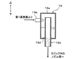
具体的には、本実施形態のエジェクタ式冷凍サイクル10bでは、図11に示すように、高段側絞り装置13として絞り開度が固定された固定絞りを採用し、低段側絞り装置16として温度式膨張弁を採用している。さらに、第1蒸発器15の冷媒出口側とエジェクタ18のノズル部18aの入口側との間に、サイクル内の余剰冷媒を蓄える貯液タンク(貯液部)19を配置している。
Specifically, in the
この貯液タンク19の詳細構成については、図12を用いて説明する。なお、図12における上下の各矢印は、貯液タンク19を車両に搭載した状態における上下の各方向を示している。
The detailed configuration of the
貯液タンク19は、上下方向に延びて両端部が閉塞された円筒状部材で形成された本体部19a、第1蒸発器15から流出した冷媒を本体部19a内へ流入させる冷媒流入ポート19b、本体部19a内から気液二相冷媒をエジェクタ18のノズル部18a側へ流出させる冷媒流出ポート19c等を有して構成されている。
The
冷媒流入ポート19bは、本体部19aの円筒状側面に接続されており本体部19aの円筒状側面の接線方向に延びる冷媒配管によって構成されている。冷媒流出ポート19cは、本体部19aの軸方向下側端面(底面)に接続されており、本体部19aの内外に亘って本体部19aと同軸上に延びる冷媒配管によって構成されている。
The
さらに、冷媒流出ポート19cの上端部は、冷媒流入ポート19bの接続部位よりも上方側まで延びている。また、冷媒流出ポート19cの下方側には、本体部19a内に貯留された液相冷媒を、冷媒流出ポート19c内へ流入させる液相冷媒導入穴19dが形成されている。
Furthermore, the upper end part of the refrigerant |
従って、サイクルを循環する循環冷媒流量が減少し、第1蒸発器15から気液二相冷媒が流出する運転条件では、冷媒流入ポート19bから本体部19a内へ流入した冷媒が本体部19aの円筒状内壁面に沿って旋回して流れ、この旋回流によって生じる遠心力の作用によって冷媒の気液が分離される。
Accordingly, under the operating conditions in which the flow rate of the circulating refrigerant circulating in the cycle decreases and the gas-liquid two-phase refrigerant flows out from the
そして、分離された液相冷媒は、重力の作用によって下方側へ落下し、余剰冷媒として本体部19a内に貯留される。一方、分離された気相冷媒は、冷媒流出ポート19cを介してノズル部18aの入口側へ流出する際に、液相冷媒導入穴19dから冷媒流出ポート19c内へ流入した液相冷媒と混合して気液二相冷媒となって流出する。
The separated liquid phase refrigerant falls downward due to the action of gravity, and is stored in the
また、サイクルを循環する循環冷媒流量が増加し、第1蒸発器15から気相冷媒が流出する運転条件では、冷媒流入ポート19bから流入した気相冷媒は気液分離されることなく、冷媒流出ポート19cを介してノズル部18aの入口側へ流出する。この際、冷媒流出ポート19cへ流入した気相冷媒は、液相冷媒導入穴19dから冷媒流出ポート19c内へ流入した液相冷媒と混合して気液二相冷媒となって流出する。
Also, under the operating conditions in which the flow rate of the circulating refrigerant circulating in the cycle increases and the gas phase refrigerant flows out from the
つまり、本実施形態の貯液タンク19は、第1蒸発器15から流出した冷媒を気液二相状態としてノズル部18aの入口側へ流出させる二相化手段を構成している。より具体的には、貯液タンク19は、本体部19aに貯液された液相冷媒と第1蒸発器15から流出した冷媒とを混合させてノズル部18aの入口側へ流出させている。
That is, the
その他のエジェクタ18およびエジェクタ式冷凍サイクル10bの構成および作動は、第1実施形態と同様である。従って、本実施形態のエジェクタ式冷凍サイクル10を作動させると、第1実施形態と同様に、車室内へ送風される室内用送風空気およびクールボックス内へ循環送風される庫内用送風空気を冷却することができる。
Other configurations and operations of the
ここで、エジェクタ18のノズル部18aへ気相冷媒を流入させる構成のエジェクタ式冷凍サイクルでは、混合部18eにて噴射冷媒と吸引冷媒とを混合させた混合冷媒の乾き度xも比較的高い値(例えば、乾き度xが0.8以上)となりやすい。
Here, in the ejector-type refrigeration cycle configured to flow the gas-phase refrigerant into the
このようなエジェクタ式冷凍サイクルでは、図25を用いて説明したように、凝縮遅れが生じて、ディフューザ部18gにおける冷媒昇圧性能を低下させてしまうことがある。また、図20、図21を用いて説明したように、ディフューザ部18gにおける冷媒昇圧性能が不安定になってしまうことがある。
In such an ejector-type refrigeration cycle, as described with reference to FIG. 25, a condensation delay may occur, and the refrigerant pressure increase performance in the
さらに、混合冷媒の乾き度xが上昇して、0.995以上の高乾き度の気液二相冷媒になってしまうと、図22、図23を用いて説明したように、本発明者らの検討によれば、エジェクタ18のディフューザ部18gが所望の冷媒昇圧性能を発揮できないばかりか、エジェクタ18の冷媒吸引口18dから吸引される吸引冷媒の流量が減少してしまうことがある。
Furthermore, when the dryness x of the mixed refrigerant increases to become a gas-liquid two-phase refrigerant having a high dryness of 0.995 or more, as described with reference to FIGS. According to the above examination, the
これに対して、本実施形態のエジェクタ式冷凍サイクル10bでは、二相化手段としての貯液タンク19を備えているので、エジェクタ18のノズル部18aへ確実に気液二相冷媒を流入させることができる。従って、凝縮遅れが生じてしまうことを確実に抑制できる。
On the other hand, since the
さらに、ノズル部18aへ気液二相冷媒を流入させて等エントロピ的に減圧させることで、冷媒噴射口18cから噴射される噴射冷媒も確実に気液二相冷媒のとなるので、混合冷媒の乾き度xが上昇してしまうことを抑制できる。従って、ディフューザ部18gにおける冷媒昇圧性能が不安定になってしまうことや、冷媒吸引口18dから吸引される吸引冷媒流量が低下してしまうことを抑制できる。
Furthermore, by causing the gas-liquid two-phase refrigerant to flow into the
これに加えて、噴射冷媒の乾き度xを低下させて、混合冷媒の二相音速αhを低下させることができるので、二相冷媒の流速が超音速状態から亜音速状態へ変化する際に生じる衝撃波を気体力学的に弱い衝撃波とすることができる。従って、ディフューザ部18gにおける冷媒昇圧性能が不安定になってしまうことを効果的に抑制できる。
In addition, since the dryness x of the injected refrigerant can be reduced to reduce the two-phase sonic speed αh of the mixed refrigerant, it occurs when the flow speed of the two-phase refrigerant changes from the supersonic state to the subsonic state. The shock wave can be a gas-weak shock wave. Therefore, it is possible to effectively suppress the refrigerant pressure increase performance in the
その結果、本実施形態のエジェクタ式冷凍サイクル10によれば、エジェクタ18のノズル部18aへ第1蒸発器15下流側冷媒を流入させるサイクル構成であっても、COPを充分に向上させることができる。
As a result, according to the
また、本実施形態では、二相化手段を貯液タンク19によって構成しているので、サイクル構成の複雑化を招くことなく、極めて簡素な構成で、エジェクタ18のノズル部18aへ確実に気液二相冷媒を流入させることができる。
Further, in this embodiment, since the two-phase unit is constituted by the
また、本実施形態のエジェクタ式冷凍サイクル10では、低段側絞り装置16として可変絞り機構である温度式膨張弁を採用し、第2蒸発器17から流出した冷媒が予め定めた基準範囲内となるようにしている。換言すると、本実施形態の低段側絞り装置16の絞り開度は、第2蒸発器17から流出した冷媒が予め定めた基準過熱度以下となるように調整される。
Further, in the ejector
従って、基準過熱度を適切に設定しておくことで、気液二相状態となっている噴射冷媒と基準過熱度以下の気相状態となっている吸引冷媒とを混合させた混合冷媒の乾き度xが上昇してしまうことを確実に抑制できる。さらに、第2蒸発器17から流出した冷媒が飽和気相冷媒あるは気液二相冷媒となるように、低段側絞り装置16の絞り開度を調整してもよい。
Therefore, by appropriately setting the reference superheat degree, the mixed refrigerant obtained by mixing the jet refrigerant that is in the gas-liquid two-phase state and the suction refrigerant that is in the gas phase state below the reference superheat degree is dried. It is possible to reliably suppress the degree x from increasing. Furthermore, the throttle opening degree of the low stage
また、本実施形態のエジェクタ18によれば、第1実施形態と同様に、ディフューザ部18gにおける冷媒昇圧性能を安定化させることができ、エジェクタ18におけるエジェクタ効率ηejを向上させることができる。その結果、本実施形態のエジェクタ式冷凍サイクル10bによれば、エジェクタ18を備えることによるCOP向上効果を充分に得ることができる。
Further, according to the
また、本実施形態のエジェクタ式冷凍サイクル10aに、第2、第3、第8、第9実施形態に開示されたエジェクタ18を適用してもよい。
Moreover, you may apply the
(第6実施形態)
本実施形態では、第5実施形態に対して、図13に示すように、エジェクタ式冷凍サイクルの構成を変更した例を説明する。
(Sixth embodiment)
In the present embodiment, an example in which the configuration of the ejector refrigeration cycle is changed as shown in FIG. 13 with respect to the fifth embodiment will be described.
具体的には、本実施形態のエジェクタ式冷凍サイクル10bでは、貯液タンク19内へ圧縮機11から吐出された気相冷媒を導く吐出冷媒通路20aを追加している。この吐出冷媒通路20aには、貯液タンク19内の冷媒圧力を上昇させないための絞り手段を設けておくことが望ましい。そこで、本実施形態では、吐出冷媒通路20aをキャピラリチューブで構成している。
Specifically, in the ejector
従って、本実施形態の二相化手段である貯液タンク19は、貯液タンク19に貯液された液相冷媒と圧縮機11から吐出された気相冷媒とを混合させてノズル部18aの入口側へ流出させるように構成されている。その他の構成および作動は第5実施形態と同様である。本実施形態のように二相化手段を構成しても、第5実施形態と同様の効果を得ることができる。
Therefore, the
また、本実施形態のエジェクタ式冷凍サイクル10aに、第2、第3、第8、第9実施形態に開示されたエジェクタ18を適用してもよい。
Moreover, you may apply the
(第7実施形態)
本実施形態では、第5実施形態に対して、図14に示すように、エジェクタ式冷凍サイクルの構成を変更した例を説明する。
(Seventh embodiment)
In the present embodiment, an example in which the configuration of the ejector refrigeration cycle is changed as shown in FIG. 14 with respect to the fifth embodiment will be described.
具体的には、本実施形態のエジェクタ式冷凍サイクル10bでは、貯液タンク19内へ放熱器12から流出した液相冷媒を導く凝縮冷媒通路20bを追加している。この凝縮冷媒通路20bには、貯液タンク19内の冷媒圧力を上昇させないための絞り手段を設けておくことが望ましい。そこで、本実施形態では、凝縮冷媒通路20bをキャピラリチューブで構成している。
Specifically, in the
従って、本実施形態の二相化手段である貯液タンク19は、放熱器12から流出した液相冷媒と第1蒸発器15から流出した気相冷媒とを混合させてノズル部18aの入口側へ流出させるように構成されている。その他の構成および作動は第5実施形態と同様である。本実施形態のように二相化手段を構成しても、第5実施形態と同様の効果を得ることができる。
Therefore, the
また、本実施形態のエジェクタ式冷凍サイクル10aに、第2、第3、第8、第9実施形態に開示されたエジェクタ18を適用してもよい。
Moreover, you may apply the
(第8実施形態)
本実施形態では、図15に示すように、第2実施形態のエジェクタ18に対して、第3実施形態と同様に、ノズル部18aの冷媒流れ上流側に設けられた筒状部18mの内部に冷媒流入口18lから流入した冷媒を旋回させる旋回空間18kを設けている。その他のエジェクタ18およびエジェクタ式冷凍サイクル10の構成および作動は、第2実施形態と同様である。
(Eighth embodiment)
In the present embodiment, as shown in FIG. 15, the
従って、本実施形態のエジェクタ式冷凍サイクル10を作動させると、第2実施形態と同様に、車室内へ送風される室内用送風空気およびクールボックス内へ循環送風される庫内用送風空気を冷却することができる。
Therefore, when the ejector
また、本実施形態のエジェクタ18では、第3実施形態と同様に、旋回空間18k内で冷媒を旋回させることによって、凝縮核の生成された気液二相冷媒をノズル部18aへ流入させることができるので、ノズル効率ηnozを向上させることができる。従って、ディフューザ部18gにおける冷媒昇圧性能の低下を抑制できる。
Further, in the
また、第2実施形態と同様に、ノズル部18aの冷媒噴射口18cから噴射される冷媒を自由膨張させるので、壁面摩擦が増加してしまうことを抑制できる。従って、ノズル部18aにおける冷媒のエネルギ損失を低減させて、エジェクタ18の冷媒昇圧性能の低下を抑制できる。
Moreover, since the refrigerant | coolant injected from the refrigerant |
さらに、第1実施形態と同様に、ディフューザ部18gにおける冷媒昇圧性能を安定化させることができ、エジェクタ18におけるエジェクタ効率ηejを向上させることができる。従って、本実施形態のエジェクタ式冷凍サイクル10では、エジェクタ18を備えることによるCOP向上効果を充分に得ることができる。
Further, similarly to the first embodiment, the refrigerant pressure-increasing performance in the
(第9実施形態)
第8実施形態では、エジェクタ18のノズル部18aとして、噴射部18jの入口部に形成される最小通路面積部の冷媒通路面積が固定された固定ノズルを採用した例を説明したが、本実施形態では、図16に示すように、最小通路面積部の冷媒通路面積を変更可能に構成された可変ノズルを採用した例を説明する。
(Ninth embodiment)
In the eighth embodiment, an example in which a fixed nozzle in which the refrigerant passage area of the minimum passage area portion formed at the inlet portion of the
具体的には、本実施形態のエジェクタ18は、ノズル部18aの冷媒通路面積を変化させる弁体としてのニードル弁18y、このニードル弁18yを変位させる駆動手段としてのステッピングモータ18xを有して構成されている。
Specifically, the
ニードル弁18yは、その中心軸がノズル部18aの中心軸と同軸上に配置された針状に形成されている。より具体的には、ニードル弁18yは、冷媒流れ下流側に向かって先細る形状に形成されており、最下流側の先細先端部がノズル部18aの冷媒噴射口18cよりも冷媒流れ下流側に向かって突出するように配置されている。つまり、本実施形態のノズル部18aは、いわゆるプラグノズルとして構成されている。
The
ステッピングモータ18xは、ノズル部18aの冷媒流入口18l側に配置されており、ニードル弁18yをノズル部18aの軸方向に変位させる。これにより、ノズル部18aの内周壁面とニードル弁18yの外周壁面との間に形成される断面円環状の冷媒通路の面積が変更される。なお、ステッピングモータ18xは、制御装置から出力される制御信号によってその作動が制御される。
The stepping
その他のエジェクタ18およびエジェクタ式冷凍サイクル10の構成および作動は、第8施形態と同様である。従って、本実施形態のエジェクタ式冷凍サイクル10およびエジェクタ18においても、第8実施形態と同様の効果を得ることができる。
Other configurations and operations of the
また、本実施形態のエジェクタ18によれば、ノズル部18aを可変ノズルとして構成しているので、エジェクタ18のノズル部18aへエジェクタ式冷凍サイクル10の負荷に応じた冷媒流量を流入させることができる。
Moreover, according to the
また、本実施形態のノズル部18aはプラグノズルとして構成されているので、噴射冷媒を冷媒噴射口18cからニードル弁18yの外表面に沿うように混合部18eへ噴射することができる。従って、ノズル部18aへ流入させる冷媒流量が変化しても、噴射冷媒を容易に自由膨張させることができ、冷媒と冷媒通路との壁面摩擦を低下させて、冷媒通路を流れる冷媒の有する運動エネルギの損失を抑制することができる。
Moreover, since the
また、本実施形態のニードル弁18yは、図16に示すように、旋回空間18k内を貫通するように配置されているので、旋回空間18kで旋回する冷媒とノズル部18aの内壁との摩擦によって凝縮核を生成しやすい。
Further, as shown in FIG. 16, the
なお、図16に示すノズル部18aでは、ニードル弁18yとして、冷媒流れ下流側に向かって先細る形状のものを採用しているが、図17に示す変形例のように、ディフューザ部18g側から、冷媒流れ上流側に向かって先細る形状のものを採用してもよい。この場合は、最上流側の先細先端部が噴射部18jよりも先細部18i側へ突出するように配置すればよい。
In addition, in the
(第10実施形態)
本実施形態では、第4実施形態に対して、エジェクタ式冷凍サイクル10aの構成を変更した例を説明する。具体的には、本実施形態のエジェクタ式冷凍サイクル10aでは、図18に示すように、高段側絞り装置13に代えて、第1減圧手段として高段側エジェクタ131を採用している。
(10th Embodiment)
This embodiment demonstrates the example which changed the structure of the ejector-
この高段側エジェクタ131の基本的構成は、上述したエジェクタ18と同様である。従って、高段側エジェクタ131もエジェクタ18と同様に、冷媒を減圧させる高段側ノズル部131a、並びに、第1蒸発器15から流出した冷媒を吸引する高段側冷媒吸引口131dおよび混合冷媒を昇圧させる高段側ディフューザ部(高段側昇圧部)131gが形成された高段側ボデー部131bを有して構成されている。
The basic configuration of the high-
ここで、本実施形態の高段側エジェクタ131の高段側ノズル部131aには、放熱器12にて凝縮した液相冷媒を流入させることができるので、高段側エジェクタ131では、高段側ノズル部131aに乾き度の高い気液二相冷媒が流入することによって高段側ディフューザ部131gが所望の昇圧性能を発揮できなくなってしまうことはない。
Here, since the liquid-phase refrigerant condensed by the
そこで、本実施形態では、高段側エジェクタ131として、上述したエジェクタ18と全く同様の構成のものではなく、高段側ノズル部131aに液相冷媒を流入させた際に、エジェクタ式冷凍サイクル10a全体として高いCOPを発揮できるように設定されたものを採用している。
Therefore, in the present embodiment, the high-
高段側エジェクタ131の高段側ディフューザ部131g出口側には、高段側エジェクタ131の高段側ディフューザ部131gから流出した冷媒の気液を分離する気液分離器21が接続されている。
A gas-
気液分離器21の液相冷媒流出口には、固定絞り22を介して、第1蒸発器15の冷媒流入口が接続され、第1蒸発器15の冷媒流出口には、高段側エジェクタ131の冷媒吸引口が接続されている。一方、気液分離器21の気相冷媒流出口には、エジェクタ18のノズル部18aの入口側が接続されている。その他の構成は第4実施形態と同様である。
A refrigerant inlet of the
従って、本実施形態のエジェクタ式冷凍サイクル10aを作動させると、放熱器12から流出した液相冷媒の流れが分岐部14にて分岐される。分岐部14にて分岐された一方の冷媒は、高段側エジェクタ131の高段側ノズル部131aへ流入して等エントロピ的に減圧されて噴射される。
Therefore, when the
そして、この噴射冷媒の吸引作用によって、第1蒸発器15から流出した冷媒が、高段側エジェクタ131の高段側冷媒吸引口131dから吸引される。高段側ノズル部131aから噴射された噴射冷媒と高段側冷媒吸引口131dから吸引された吸引冷媒との混合冷媒は、高段側ディフューザ部131gへ流入して昇圧される。
The refrigerant flowing out of the
高段側ディフューザ部131gから流出した冷媒は、気液分離器21へ流入して気液分離される。そして、気液分離器21にて分離された液相冷媒は、固定絞り22を介して第1蒸発器15へ流入する。一方、気液分離器21にて分離された気相冷媒は、エジェクタ18のノズル部18aへ流入する。その他の作動は、第4実施形態と同様である。
The refrigerant that has flowed out of the high stage
従って、本実施形態のエジェクタ式冷凍サイクル10aによれば、第4実施形態と同様の効果を得られるだけでなく、高段側エジェクタ131の昇圧作用によって圧縮機11の消費動力を低減でき、サイクル全体としてのCOPをより一層向上させることができる。
Therefore, according to the ejector
なお、第1減圧手段として高段側エジェクタ131を採用するエジェクタ式冷凍サイクル10aは、図18に示されるサイクル構成に限定されることなく、例えば、図19に示すように構成してもよい。
The ejector-
具体的には、図19に示すエジェクタ式冷凍サイクル10aでは、高段側エジェクタ131の高段側ディフューザ部131gの出口側に第1蒸発器15の冷媒入口側を接続し、さらに、分岐部(第1分岐部)14の他方の冷媒流出口に、さらに冷媒の流れを分岐する第2分岐部14aを接続している。
Specifically, in the ejector-
そして、第2分岐部14aの一方の冷媒流出口に、固定絞り132を介して第3蒸発器23の冷媒流入口を接続し、第3蒸発器23の冷媒流出口に高段側エジェクタ131の高段側冷媒吸引口131dを接続している。第3蒸発器23は、固定絞り132にて減圧された低圧冷媒と第3送風ファン23aから送風される送風空気とを熱交換させることによって、低圧冷媒を蒸発させて吸熱作用を発揮させる吸熱用熱交換器である。
Then, the refrigerant inlet of the third evaporator 23 is connected to one refrigerant outlet of the
また、第2分岐部14aの他方の冷媒流出口に、低段側絞り装置16を介して第2蒸発器17の冷媒流入口を接続している。その他の構成は第4実施形態と同様である。このようなサイクル構成としても、高段側エジェクタ131の昇圧作用によって、サイクル全体としてのCOPをより一層向上させることができる。
In addition, the refrigerant inlet of the
(他の実施形態)
本発明は上述の実施形態に限定されることなく、本発明の趣旨を逸脱しない範囲内で、以下のように種々変形可能である。
(Other embodiments)
The present invention is not limited to the above-described embodiment, and can be variously modified as follows without departing from the spirit of the present invention.
(1)上述の実施形態では、エジェクタ18を備えるエジェクタ式冷凍サイクル10、10a、10bを車両用冷凍サイクル装置に適用し、第1蒸発器15にて室内用送風空気を冷却し、第2蒸発器17にて庫内用送風空気を冷却するようにした例を説明したが、エジェクタ式冷凍サイクル10〜10bの適用はこれに限定されない。
(1) In the above-described embodiment, the
例えば、車両用冷凍サイクル装置に適用する場合は、第1蒸発器15にて車両前席側へ送風される前席用送風空気を冷却し、第2蒸発器17にて車両後席側へ送風される後席用送風空気を冷却するようにしてもよい。
For example, when applied to a vehicle refrigeration cycle apparatus, the front-seat air blown to the front seat side of the vehicle is cooled by the
また、例えば、冷蔵冷凍装置に適用する場合は、第1蒸発器15にて、食品・飲料水等を低温(具体的には、0℃〜10℃)で冷蔵保存する冷蔵室へ送風される冷蔵室用送風空気を冷却し、第2蒸発器17にて、食品等を極低温(具体的には、−20℃〜−10℃)で冷凍保存する冷凍室へ送風される冷凍室用送風空気を冷却するようにしてもよい。
Further, for example, when applied to a refrigeration refrigerator, the
(2)上述の実施形態では、エジェクタ18をエジェクタ式冷凍サイクル10〜10bに適用した例を説明したが、エジェクタ18の適用可能なサイクル構成は、これらに限定されない。
(2) In the above-described embodiment, the example in which the
例えば、エジェクタ式冷凍サイクル10〜10bにおいて、エジェクタ18のディフューザ部18gの出口側と圧縮機11の吸入口側との間に、ディフューザ部18gから流出した冷媒の気液を分離し、分離された気相冷媒を圧縮機11の吸入口側へ流出させるアキュムレータを配置してもよい。
For example, in the ejector refrigeration cycles 10 to 10b, the gas-liquid refrigerant flowing out from the
また、放熱器12の冷媒出口側に、放熱器12から流出した冷媒の気液を分離して、下流側へ液相冷媒を流出させる受益器を配置してもよい。また、放熱器12から流出した高温冷媒と圧縮機11へ吸入される低温冷媒とを熱交換させる内部熱交換器を配置してもよい。さらに、第2蒸発器17の冷媒出口側とエジェクタ18の冷媒吸引口18dとの間に冷媒圧送用の補助ポンプを設けてもよい。
Moreover, you may arrange | position the beneficiary device which isolate | separates the gas-liquid of the refrigerant | coolant which flowed out from the
(3)上述の実施形態では、高段側絞り装置13、低段側絞り装置16として、温度式膨張弁、固定絞り、高段側エジェクタを採用した例を説明したが、高段側絞り装置13、低段側絞り装置16として、絞り開度を変更可能に構成された弁体と、この弁体の絞り開度を変化させるステッピングモータからなる電動アクチュエータとを有して構成された電気式の可変絞り機構を採用してもよい。
(3) In the above-described embodiment, the example in which the temperature type expansion valve, the fixed throttle, and the high stage side ejector are employed as the high stage
また、上述の実施形態では、放熱器12として、圧縮機11吐出冷媒と外気とを熱交換させる熱交換部からなるものを採用した例を説明したが、放熱器12として、圧縮機11吐出冷媒と外気とを熱交換させて圧縮機11吐出冷媒を凝縮させる凝縮部、この凝縮部から流出した冷媒の気液を分離するモジュレータ部、およびモジュレータ部から流出した液相冷媒と外気とを熱交換させて液相冷媒を過冷却する過冷却部を有して構成される、いわゆるサブクール型の凝縮器を採用してもよい。
Moreover, although the above-mentioned embodiment demonstrated the example which employ | adopted what consists of the heat exchange part which heat-exchanges the
また、上述の実施形態では、エジェクタ18のボデー部18b等の構成部材を金属で形成した例を説明したが、それぞれの構成部材の機能を発揮可能であれば材質は限定されない。つまり、これらの構成部材を樹脂にて形成してもよい。
Moreover, although the above-mentioned embodiment demonstrated the example which formed structural members, such as the
(4)上述の実施形態では、ディフューザ部18gの入口部18hの冷媒通路面積を、ノズル部18acの冷媒噴射口18cの冷媒通路面積よりも小さく設定した例を説明したが、具体的には、冷媒噴射口18cの開口径を入口部18hの開口径よりも小さく設定すればよい。
(4) In the above-described embodiment, the example in which the refrigerant passage area of the
また、入口部18hの開口径を冷媒噴射口18cの開口径よりも大きく設定した場合は、入口部18hに冷媒通路内へ向かって突出する突起部を設けることによって、入口部18hの冷媒通路面積を、冷媒噴射口18cの冷媒通路面積よりも小さくすればよい。
Further, when the opening diameter of the
(5)上述の第9実施形態では、弁体(ニードル弁18y)によってノズル部18a内に形成される冷媒通路の最小通路面積部の冷媒通路面積を変更可能とした例を説明したが、弁体としてノズル部18a内に形成される冷媒通路からディフューザ部18gの内部へ亘って延びる円錐形状のものを採用し、ノズル部18aの最小通路面積部と同時にディフューザ部18gの冷媒通路面積を変更させる構成としてもよい。
(5) In the above-described ninth embodiment, the example in which the refrigerant passage area of the minimum passage area portion of the refrigerant passage formed in the
(6)上述の実施形態では、冷媒としてR134aを採用した例を説明したが、冷媒はこれに限定されない。例えば、R600a、R1234yf、R410A、R404A、R32、R1234yfxf、R407C等を採用することができる。または、これらの冷媒のうち複数種を混合させた混合冷媒等を採用してもよい。 (6) In the above-described embodiment, the example in which R134a is adopted as the refrigerant has been described, but the refrigerant is not limited to this. For example, R600a, R1234yf, R410A, R404A, R32, R1234yfxf, R407C, etc. can be employed. Or you may employ | adopt the mixed refrigerant | coolant etc. which mixed multiple types among these refrigerant | coolants.
(7)また、上記各実施形態に開示された手段は、実施可能な範囲で適宜組み合わせてもよい。例えば、第5〜第7実施形態で説明した二相化手段を第4実施形態で説明したエジェクタ式冷凍サイクル10aに適用してもよい。例えば、第10実施形態で説明したエジェクタ式冷凍サイクル10aのエジェクタ18として、第2、第3、第8、第9実施形態に開示したエジェクタ18を適用してもよい。
(7) The means disclosed in each of the above embodiments may be appropriately combined within a practicable range. For example, the biphasic means described in the fifth to seventh embodiments may be applied to the
(8)上述の実施形態では、放熱器12を冷媒と外気とを熱交換させる室外側熱交換器とし、第1、第2蒸発器15、17を送風空気を冷却する利用側熱交換器として用いているが、逆に、第1、第2蒸発器15、17を外気等の熱源から吸熱する室外側熱交換器として構成し、放熱器12を空気あるいは水等の被加熱流体を加熱する室内側熱交換器として構成するヒートポンプサイクルに本発明を適用してもよい。
(8) In the above-described embodiment, the
10、10a、10 エジェクタ式冷凍サイクル
15、17 第1、第2蒸発器
18 エジェクタ
18a ノズル部
18b ボデー部
18c 冷媒噴射口
18d 冷媒吸引口
18e 混合部
18g ディフューザ部
18h 入口部
10, 10a, 10
Claims (14)
前記圧縮機(11)から吐出された冷媒を放熱させる放熱器(12)と、
前記放熱器(12)下流側の冷媒を減圧させる第1減圧手段(13)および第2減圧手段(16)と、
前記第1減圧手段(13)にて減圧された冷媒を蒸発させる第1蒸発器(15)と、
前記第2減圧手段(16)にて減圧された冷媒を蒸発させる第2蒸発器(17)と、
前記第1蒸発器(15)下流側冷媒を減圧させるノズル部(18a)から噴射される高速度の噴射冷媒の吸引作用によって冷媒吸引口(18d)から前記第2蒸発器(17)下流側冷媒を吸引し、前記噴射冷媒と前記冷媒吸引口(18d)から吸引された吸引冷媒とを混合させて昇圧させる昇圧部(18g)を有するエジェクタ(18)とを備え、
さらに、前記第1蒸発器(15)から流出した冷媒を気液二相状態として前記ノズル部(18a)へ流入させる二相化手段(19)を備えることを特徴とするエジェクタ式冷凍サイクル。 A compressor (11) for compressing and discharging the refrigerant;
A radiator (12) for radiating the refrigerant discharged from the compressor (11);
A first decompression means (13) and a second decompression means (16) for decompressing the refrigerant on the downstream side of the radiator (12);
A first evaporator (15) for evaporating the refrigerant depressurized by the first depressurization means (13);
A second evaporator (17) for evaporating the refrigerant decompressed by the second decompression means (16);
The second evaporator (17) downstream refrigerant from the refrigerant suction port (18d) by the suction action of the high-speed jet refrigerant injected from the nozzle part (18a) for depressurizing the first refrigerant (15) downstream refrigerant. And an ejector (18) having a pressure increasing part (18g) for mixing and increasing the pressure of the injected refrigerant and the suction refrigerant sucked from the refrigerant suction port (18d),
The ejector-type refrigeration cycle further comprises a two-phase means (19) for causing the refrigerant flowing out from the first evaporator (15) to flow into the nozzle part (18a) in a gas-liquid two-phase state.
前記第2減圧手段(16)の絞り開度は、前記第2蒸発器(17)流出冷媒が気液二相冷媒あるいは予め定めた基準過熱度以下となるように調整されることを特徴とする請求項1ないし4のいずれか1つに記載のエジェクタ式冷凍サイクル。 The second pressure reducing means (16) is composed of a variable throttle mechanism configured to be able to change the throttle opening.
The throttle opening degree of the second decompression means (16) is adjusted so that the refrigerant flowing out of the second evaporator (17) is less than a gas-liquid two-phase refrigerant or a predetermined reference superheat degree. The ejector type refrigeration cycle according to any one of claims 1 to 4.
前記ボデー部(18b)の内部空間のうち、前記ノズル部(18a)の冷媒噴射口(18c)から前記昇圧部(18g)の入口部(18h)へ至る範囲には、前記噴射冷媒と前記吸引冷媒とを混合させる混合部(18e)が形成されており、
前記混合部(18e)における前記冷媒噴射口(18c)から前記入口部(18h)へ至る距離(La)は、前記入口部(18h)へ流入する冷媒の流速が二相音速以下となるように決定されていることを特徴とする請求項1ないし5のいずれか1つに記載のエジェクタ式冷凍サイクル。 The ejector (18) has a body part (18b) that forms the refrigerant suction port (18d) and the pressure increasing part (18g),
In the internal space of the body part (18b), the range of the refrigerant from the refrigerant injection port (18c) of the nozzle part (18a) to the inlet part (18h) of the pressure increasing part (18g) A mixing part (18e) for mixing the refrigerant is formed,
The distance (La) from the refrigerant injection port (18c) to the inlet part (18h) in the mixing part (18e) is such that the flow rate of the refrigerant flowing into the inlet part (18h) is equal to or lower than the two-phase sound speed. The ejector refrigeration cycle according to any one of claims 1 to 5, wherein the ejector refrigeration cycle is determined.
前記冷媒噴射口(18c)を含む前記ノズル部(18a)の軸方向垂直断面における、前記冷媒噴射口(18c)の開口断面積と前記吸引冷媒が流通する吸引通路(18f)の通路断面積の合計値を円に換算したときの直径をDaとしたときに、
La/Da≦1
となっていることを特徴とする請求項6に記載のエジェクタ式冷凍サイクル。 The distance from the refrigerant injection port (18c) in the mixing unit (18e) to the inlet unit (18h) is La,
The cross-sectional area of the opening of the refrigerant injection port (18c) and the cross-sectional area of the suction passage (18f) through which the suction refrigerant flows in the axially vertical cross section of the nozzle portion (18a) including the refrigerant injection port (18c). When the diameter when the total value is converted into a circle is Da,
La / Da ≦ 1
The ejector refrigeration cycle according to claim 6, wherein:
前記ボデー部(18b)の内部空間のうち、前記ノズル部(18a)の冷媒噴射口(18c)から前記昇圧部(18g)の入口部(18h)へ至る範囲には、前記噴射冷媒と前記吸引冷媒とを混合させる混合部(18e)が形成されており、
前記ノズル部(18a)内に形成される冷媒通路として、冷媒通路面積を徐々に縮小させる先細部(18i)、および前記先細部(18i)から前記冷媒噴射口(18c)へ冷媒を導く噴射部(18j)が設けられており、
前記ノズル部(18a)は、前記噴射部(18j)の軸方向断面における拡がり角度(θn)が、0°以上となっていることによって、前記混合部(18e)へ噴射される前記噴射冷媒を自由膨張させるように形成されていることを特徴とする請求項1ないし7のいずれか1つに記載のエジェクタ式冷凍サイクル。 The ejector (18) has a body part (18b) that forms the refrigerant suction port (18d) and the pressure increasing part (18g),
In the internal space of the body part (18b), the range of the refrigerant from the refrigerant injection port (18c) of the nozzle part (18a) to the inlet part (18h) of the pressure increasing part (18g) A mixing part (18e) for mixing the refrigerant is formed,
As the refrigerant passage formed in the nozzle portion (18a), a tapered portion (18i) that gradually reduces the refrigerant passage area, and an injection portion that guides the refrigerant from the tapered portion (18i) to the refrigerant injection port (18c). (18j) is provided,
The nozzle part (18a) is configured to allow the jet refrigerant to be jetted to the mixing part (18e) when the spread angle (θn) in the axial section of the jet part (18j) is 0 ° or more. 8. The ejector refrigeration cycle according to claim 1, wherein the ejector refrigeration cycle is formed so as to freely expand.
Lb/Db≦1
となっていることを特徴とする請求項10に記載のエジェクタ式冷凍サイクル。 When the axial length of the cylindrical portion of the mixing portion (18e) is Lb and the diameter of the cylindrical portion is Db,
Lb / Db ≦ 1
The ejector refrigeration cycle according to claim 10, wherein:
Priority Applications (2)
| Application Number | Priority Date | Filing Date | Title |
|---|---|---|---|
| JP2013127580A JP5962596B2 (en) | 2013-06-18 | 2013-06-18 | Ejector refrigeration cycle |
| PCT/JP2014/002784 WO2014203460A1 (en) | 2013-06-18 | 2014-05-27 | Ejector refrigeration cycle |
Applications Claiming Priority (1)
| Application Number | Priority Date | Filing Date | Title |
|---|---|---|---|
| JP2013127580A JP5962596B2 (en) | 2013-06-18 | 2013-06-18 | Ejector refrigeration cycle |
Publications (2)
| Publication Number | Publication Date |
|---|---|
| JP2015001365A JP2015001365A (en) | 2015-01-05 |
| JP5962596B2 true JP5962596B2 (en) | 2016-08-03 |
Family
ID=52104213
Family Applications (1)
| Application Number | Title | Priority Date | Filing Date |
|---|---|---|---|
| JP2013127580A Active JP5962596B2 (en) | 2013-06-18 | 2013-06-18 | Ejector refrigeration cycle |
Country Status (2)
| Country | Link |
|---|---|
| JP (1) | JP5962596B2 (en) |
| WO (1) | WO2014203460A1 (en) |
Families Citing this family (4)
| Publication number | Priority date | Publication date | Assignee | Title |
|---|---|---|---|---|
| JP6277869B2 (en) | 2014-05-30 | 2018-02-14 | 株式会社デンソー | Ejector refrigeration cycle |
| JP6287890B2 (en) | 2014-09-04 | 2018-03-07 | 株式会社デンソー | Liquid jet ejector and ejector refrigeration cycle |
| EP3246637B1 (en) * | 2015-01-16 | 2021-06-16 | Mitsubishi Electric Corporation | Refrigeration cycle device |
| JP6708161B2 (en) * | 2017-04-24 | 2020-06-10 | 株式会社デンソー | Ejector type refrigeration cycle |
Family Cites Families (7)
| Publication number | Priority date | Publication date | Assignee | Title |
|---|---|---|---|---|
| JP3931226B2 (en) * | 2002-03-12 | 2007-06-13 | 独立行政法人産業技術総合研究所 | Ejector type refrigeration apparatus and ejector used in the apparatus |
| JP2009133624A (en) * | 2005-03-14 | 2009-06-18 | Mitsubishi Electric Corp | Refrigerating/air-conditioning device |
| JP4604909B2 (en) * | 2005-08-08 | 2011-01-05 | 株式会社デンソー | Ejector type cycle |
| JP2009236330A (en) * | 2008-03-25 | 2009-10-15 | Calsonic Kansei Corp | Cooling system |
| WO2012074650A1 (en) * | 2010-11-30 | 2012-06-07 | Carrier Corporation | Ejector |
| JP5419901B2 (en) * | 2011-01-17 | 2014-02-19 | 三菱電機株式会社 | Refrigeration cycle apparatus, flow path switching apparatus, and flow path switching method |
| JP6102552B2 (en) * | 2012-11-16 | 2017-03-29 | 株式会社デンソー | Refrigeration cycle equipment |
-
2013
- 2013-06-18 JP JP2013127580A patent/JP5962596B2/en active Active
-
2014
- 2014-05-27 WO PCT/JP2014/002784 patent/WO2014203460A1/en active Application Filing
Also Published As
| Publication number | Publication date |
|---|---|
| WO2014203460A1 (en) | 2014-12-24 |
| JP2015001365A (en) | 2015-01-05 |
Similar Documents
| Publication | Publication Date | Title |
|---|---|---|
| JP6115344B2 (en) | Ejector | |
| JP6115345B2 (en) | Ejector | |
| JP6384374B2 (en) | Ejector refrigeration cycle | |
| JP5999050B2 (en) | Ejector refrigeration cycle and ejector | |
| JP6299495B2 (en) | Ejector refrigeration cycle | |
| JP6048339B2 (en) | Ejector | |
| JP6119489B2 (en) | Ejector | |
| JP6056596B2 (en) | Ejector | |
| JP2010116927A (en) | Ejector | |
| JP2018119542A (en) | Ejector | |
| JP5962596B2 (en) | Ejector refrigeration cycle | |
| JP5962571B2 (en) | Ejector | |
| WO2014108974A1 (en) | Ejector | |
| WO2014080596A1 (en) | Ejector | |
| WO2021261112A1 (en) | Ejector | |
| WO2019208428A1 (en) | Ejector-type refrigeration cycle | |
| JP4888050B2 (en) | Refrigeration cycle equipment | |
| JP6511873B2 (en) | Ejector and ejector-type refrigeration cycle | |
| WO2016185664A1 (en) | Ejector, and ejector-type refrigeration cycle | |
| JP6780567B2 (en) | Gas-liquid separator and refrigeration cycle equipment | |
| WO2018139417A1 (en) | Ejector | |
| WO2017187932A1 (en) | Decompression device and refrigeration cycle device | |
| JP2004324929A (en) | Ejector cycle |
Legal Events
| Date | Code | Title | Description |
|---|---|---|---|
| A621 | Written request for application examination |
Free format text: JAPANESE INTERMEDIATE CODE: A621 Effective date: 20150910 |
|
| TRDD | Decision of grant or rejection written | ||
| A01 | Written decision to grant a patent or to grant a registration (utility model) |
Free format text: JAPANESE INTERMEDIATE CODE: A01 Effective date: 20160531 |
|
| A61 | First payment of annual fees (during grant procedure) |
Free format text: JAPANESE INTERMEDIATE CODE: A61 Effective date: 20160613 |
|
| R151 | Written notification of patent or utility model registration |
Ref document number: 5962596 Country of ref document: JP Free format text: JAPANESE INTERMEDIATE CODE: R151 |
|
| R250 | Receipt of annual fees |
Free format text: JAPANESE INTERMEDIATE CODE: R250 |
|
| R250 | Receipt of annual fees |
Free format text: JAPANESE INTERMEDIATE CODE: R250 |
|
| R250 | Receipt of annual fees |
Free format text: JAPANESE INTERMEDIATE CODE: R250 |
|
| R250 | Receipt of annual fees |
Free format text: JAPANESE INTERMEDIATE CODE: R250 |
|
| R250 | Receipt of annual fees |
Free format text: JAPANESE INTERMEDIATE CODE: R250 |
|
| R250 | Receipt of annual fees |
Free format text: JAPANESE INTERMEDIATE CODE: R250 |