JP5950072B1 - Shock absorbing steering device - Google Patents
Shock absorbing steering device Download PDFInfo
- Publication number
- JP5950072B1 JP5950072B1 JP2016514197A JP2016514197A JP5950072B1 JP 5950072 B1 JP5950072 B1 JP 5950072B1 JP 2016514197 A JP2016514197 A JP 2016514197A JP 2016514197 A JP2016514197 A JP 2016514197A JP 5950072 B1 JP5950072 B1 JP 5950072B1
- Authority
- JP
- Japan
- Prior art keywords
- column
- absorbing member
- energy absorbing
- steering
- pair
- Prior art date
- Legal status (The legal status is an assumption and is not a legal conclusion. Google has not performed a legal analysis and makes no representation as to the accuracy of the status listed.)
- Active
Links
- 230000035939 shock Effects 0.000 title claims description 22
- 230000002093 peripheral effect Effects 0.000 claims abstract description 33
- 238000010521 absorption reaction Methods 0.000 claims description 57
- 229910001369 Brass Inorganic materials 0.000 claims description 8
- 239000010951 brass Substances 0.000 claims description 8
- 238000003825 pressing Methods 0.000 claims description 7
- 238000009434 installation Methods 0.000 claims description 5
- 230000007423 decrease Effects 0.000 claims description 4
- 230000001105 regulatory effect Effects 0.000 claims description 2
- 230000007246 mechanism Effects 0.000 description 16
- 239000002775 capsule Substances 0.000 description 14
- 238000006073 displacement reaction Methods 0.000 description 13
- 239000000463 material Substances 0.000 description 11
- 229910052751 metal Inorganic materials 0.000 description 8
- 239000002184 metal Substances 0.000 description 8
- 239000004033 plastic Substances 0.000 description 7
- 125000006850 spacer group Chemical group 0.000 description 7
- 229920003002 synthetic resin Polymers 0.000 description 7
- 239000000057 synthetic resin Substances 0.000 description 7
- 230000008878 coupling Effects 0.000 description 6
- 238000010168 coupling process Methods 0.000 description 6
- 238000005859 coupling reaction Methods 0.000 description 6
- 230000003247 decreasing effect Effects 0.000 description 4
- 229920001343 polytetrafluoroethylene Polymers 0.000 description 4
- 239000004810 polytetrafluoroethylene Substances 0.000 description 4
- 229920005989 resin Polymers 0.000 description 4
- 239000011347 resin Substances 0.000 description 4
- 229910000838 Al alloy Inorganic materials 0.000 description 3
- 229910052782 aluminium Inorganic materials 0.000 description 3
- XAGFODPZIPBFFR-UHFFFAOYSA-N aluminium Chemical compound [Al] XAGFODPZIPBFFR-UHFFFAOYSA-N 0.000 description 3
- 229920006324 polyoxymethylene Polymers 0.000 description 3
- -1 polytetrafluoroethylene Polymers 0.000 description 3
- 230000002265 prevention Effects 0.000 description 3
- 239000004677 Nylon Substances 0.000 description 2
- 229920006748 POM-GF25 Polymers 0.000 description 2
- 229930182556 Polyacetal Natural products 0.000 description 2
- 238000004512 die casting Methods 0.000 description 2
- 230000006872 improvement Effects 0.000 description 2
- 150000002739 metals Chemical class 0.000 description 2
- 238000000034 method Methods 0.000 description 2
- 229920001778 nylon Polymers 0.000 description 2
- 229920006122 polyamide resin Polymers 0.000 description 2
- 238000003466 welding Methods 0.000 description 2
- 229910000975 Carbon steel Inorganic materials 0.000 description 1
- CWYNVVGOOAEACU-UHFFFAOYSA-N Fe2+ Chemical compound [Fe+2] CWYNVVGOOAEACU-UHFFFAOYSA-N 0.000 description 1
- FYYHWMGAXLPEAU-UHFFFAOYSA-N Magnesium Chemical compound [Mg] FYYHWMGAXLPEAU-UHFFFAOYSA-N 0.000 description 1
- 229910000831 Steel Inorganic materials 0.000 description 1
- RTAQQCXQSZGOHL-UHFFFAOYSA-N Titanium Chemical compound [Ti] RTAQQCXQSZGOHL-UHFFFAOYSA-N 0.000 description 1
- 239000010953 base metal Substances 0.000 description 1
- 238000005452 bending Methods 0.000 description 1
- 239000010962 carbon steel Substances 0.000 description 1
- 230000008859 change Effects 0.000 description 1
- 238000006243 chemical reaction Methods 0.000 description 1
- 239000003638 chemical reducing agent Substances 0.000 description 1
- 239000011247 coating layer Substances 0.000 description 1
- 238000005520 cutting process Methods 0.000 description 1
- 230000000694 effects Effects 0.000 description 1
- 230000003028 elevating effect Effects 0.000 description 1
- 230000002708 enhancing effect Effects 0.000 description 1
- 238000005304 joining Methods 0.000 description 1
- 239000011777 magnesium Substances 0.000 description 1
- 229910052749 magnesium Inorganic materials 0.000 description 1
- 230000000116 mitigating effect Effects 0.000 description 1
- 230000004048 modification Effects 0.000 description 1
- 238000012986 modification Methods 0.000 description 1
- 229910000510 noble metal Inorganic materials 0.000 description 1
- 230000009467 reduction Effects 0.000 description 1
- 238000005096 rolling process Methods 0.000 description 1
- 239000010959 steel Substances 0.000 description 1
- 230000003746 surface roughness Effects 0.000 description 1
- 239000010936 titanium Substances 0.000 description 1
- 229910052719 titanium Inorganic materials 0.000 description 1
- XLYOFNOQVPJJNP-UHFFFAOYSA-N water Substances O XLYOFNOQVPJJNP-UHFFFAOYSA-N 0.000 description 1
Images


Classifications
-
- B—PERFORMING OPERATIONS; TRANSPORTING
- B62—LAND VEHICLES FOR TRAVELLING OTHERWISE THAN ON RAILS
- B62D—MOTOR VEHICLES; TRAILERS
- B62D1/00—Steering controls, i.e. means for initiating a change of direction of the vehicle
- B62D1/02—Steering controls, i.e. means for initiating a change of direction of the vehicle vehicle-mounted
- B62D1/16—Steering columns
- B62D1/18—Steering columns yieldable or adjustable, e.g. tiltable
- B62D1/19—Steering columns yieldable or adjustable, e.g. tiltable incorporating energy-absorbing arrangements, e.g. by being yieldable or collapsible
- B62D1/195—Yieldable supports for the steering column
-
- B—PERFORMING OPERATIONS; TRANSPORTING
- B62—LAND VEHICLES FOR TRAVELLING OTHERWISE THAN ON RAILS
- B62D—MOTOR VEHICLES; TRAILERS
- B62D1/00—Steering controls, i.e. means for initiating a change of direction of the vehicle
- B62D1/02—Steering controls, i.e. means for initiating a change of direction of the vehicle vehicle-mounted
- B62D1/16—Steering columns
- B62D1/18—Steering columns yieldable or adjustable, e.g. tiltable
- B62D1/19—Steering columns yieldable or adjustable, e.g. tiltable incorporating energy-absorbing arrangements, e.g. by being yieldable or collapsible
- B62D1/192—Yieldable or collapsible columns
Landscapes
- Engineering & Computer Science (AREA)
- Chemical & Material Sciences (AREA)
- Combustion & Propulsion (AREA)
- Transportation (AREA)
- Mechanical Engineering (AREA)
- Steering Controls (AREA)
- Vibration Dampers (AREA)
Abstract
エネルギ吸収部材(35a)は、インナコラム(14a)の外周面に固定され、前後方向に延びてアウタコラム(13a)のスリット(43)の内側に入り込んでいる。二次衝突時に締付杆(27a)がアウタコラム(13a)と共に前方へ変位することによって、エネルギ吸収部材(35a)は、上下方向から締付杆(27a)及びインナコラム(14a)に拘束されながら、締付杆(27a)に潰されて衝撃吸収荷重を発生する。The energy absorbing member (35a) is fixed to the outer peripheral surface of the inner column (14a), extends in the front-rear direction, and enters the inside of the slit (43) of the outer column (13a). When the fastening rod (27a) is displaced forward together with the outer column (13a) at the time of the secondary collision, the energy absorbing member (35a) is restrained by the fastening rod (27a) and the inner column (14a) from the vertical direction. However, it is crushed by the fastening rod (27a) to generate an impact absorbing load.
Description
この発明は、衝突事故の際に、運転者の身体からステアリングホイールに加わった衝撃エネルギを吸収しつつ、ステアリングホイールの前方への変位を可能とする、衝撃吸収式ステアリング装置の改良に関する。具体的には、衝突事故の際のエネルギ吸収特性を向上させる事により、運転者の保護充実を図れる構造の実現を図るものである。 The present invention relates to an improvement of an impact absorption type steering device that enables displacement of a steering wheel forward while absorbing impact energy applied to the steering wheel from a driver's body in a collision accident. Specifically, it is intended to realize a structure capable of enhancing the protection of the driver by improving the energy absorption characteristics in the event of a collision.
自動車用ステアリング装置は、図14に示す様に構成され、ステアリングホイール1の回転をステアリングギヤユニット2の入力軸3に伝達し、入力軸3の回転に伴って左右1対のタイロッド4、4を押し引きして、前車輪に舵角を付与する。ステアリングホイール1は、ステアリングシャフト5の後端部に支持固定されている。ステアリングシャフト5は、円筒状のステアリングコラム6を軸方向に挿通した状態で、このステアリングコラム6に回転自在に支持されている。又、ステアリングシャフト5の前端部は、自在継手7を介して中間シャフト8の後端部に接続されている。中間シャフト8の前端部は、別の自在継手9を介して、入力軸3に接続されている。
The automobile steering device is configured as shown in FIG. 14, and transmits the rotation of the steering wheel 1 to the input shaft 3 of the
上述の様な自動車用ステアリング装置は、衝突事故の際に、衝撃エネルギを吸収しつつ、ステアリングホイールを前方に変位させる構造である事が、運転者の保護の為には必要である。即ち、衝突事故の際には、自動車が他の自動車等にぶつかる一次衝突に続いて、運転者の身体がステアリングホイールに衝突する二次衝突が発生する。この二次衝突の際に、運転者の身体に加わる衝撃を緩和して、運転者の保護を図る為の技術が従来から知られ、且つ、広く実施されている。例えば特許文献1には、ステアリングホイールを支持したステアリングコラムを、車体に対して二次衝突に伴う前方への衝撃荷重により前方に脱落可能に支持すると共に、ステアリングコラムと共に前方に変位する部分と車体との間に、塑性変形する事で衝撃荷重を吸収するエネルギ吸収部材を設ける事が記載されている。 In order to protect the driver, it is necessary that the above-described automobile steering device has a structure that displaces the steering wheel forward while absorbing impact energy in the event of a collision. That is, in the case of a collision accident, a secondary collision in which the driver's body collides with the steering wheel occurs following a primary collision in which the automobile collides with another automobile or the like. 2. Description of the Related Art Conventionally, a technique for mitigating an impact applied to a driver's body during the secondary collision and protecting the driver has been known and widely implemented. For example, in Patent Document 1, a steering column that supports a steering wheel is supported so as to be able to drop forward due to a forward impact load due to a secondary collision with the vehicle body, and a portion that is displaced forward together with the steering column and the vehicle body The provision of an energy absorbing member that absorbs an impact load by plastic deformation is described.
図15〜18は、衝撃吸収機能を備えた自動車用ステアリング装置の具体的構造の1例を示している。この従前のステアリング装置は、ステアリングホイール1(図14参照)の上下位置を調節する為のチルト機構及び前後位置を調節する為のテレスコピック機構を備える。また、このステアリング装置は、ステアリングコラム6aと、支持ブラケット10と、ステアリングコラム6a側に設けた左右1対の被挟持壁部11、11と、車体側ブラケット12と、を備える。ステアリングコラム6aは、後側のアウタコラム13の前部と、前側のインナコラム14の後部と、を軸方向の相対変位を可能に嵌合させる事により、全長を伸縮可能に構成されている。ステアリングコラム6aの内径側には、ステアリングシャフト5aを、回転自在に支持している。ステアリングシャフト5aに関しても、アウタシャフトとインナシャフトとの組み合わせにより、全長を伸縮可能に構成されている。
FIGS. 15-18 has shown an example of the specific structure of the steering device for motor vehicles provided with the impact absorption function. This conventional steering device includes a tilt mechanism for adjusting the vertical position of the steering wheel 1 (see FIG. 14) and a telescopic mechanism for adjusting the front-back position. The steering apparatus includes a
ステアリングコラム6aの前端部には、電動モータ15(図14参照)や減速機等、電動式パワーステアリング装置の構成部材を設置する為のハウジング16が結合固定されている。ハウジング16は、上部に幅方向(車両への組み付け状態で、当該車両の幅方向)に設けた支持管17を挿通した図示しないボルトにより、車体の一部に、揺動変位を可能に支持する。ステアリングシャフト5aの後端部でステアリングコラム6aよりも後方に突出した部分に、ステアリングホイール1を固定する。又、ステアリングシャフト5aの前端部でステアリングコラム6aよりも前方に突出した部分は、自在継手7を介して中間シャフト8(図14参照)に連結する。
A
又、支持ブラケット10は車体側ブラケット12に対し、二次衝突に基づく衝撃荷重により前方への変位(離脱)を可能に結合支持している。支持ブラケット10は、それぞれが鋼板等の、十分な強度及び剛性を有する金属板製である、天板18と左右1対の側板19a、19bとを、溶接等により結合固定して成る。天板18の幅方向両端部を、支持ブラケット10を車体側ブラケット12に結合支持する為の結合板部20、20としている。両結合板部20、20の幅方向中央部には、図18に示す様な、それぞれが両結合板部20、20の後端縁に開口する切欠き21、21が形成される。両切欠き21、21には、カプセル22、22が装着されている。
Further, the
両カプセル22、22は、合成樹脂、アルミニウム系合金の如き軟質金属等、天板18を構成する金属板に対し滑り易い材料により造っている。この様な両カプセル22、22は、通常状態では両切欠き21、21から抜け出る事はないが、支持ブラケット10に前方に向いた大きな衝撃荷重が加わった場合には、両切欠き21、21との係合部(例えば、天板18と両カプセル22、22との間に掛け渡された止めピン)を裂断して、両切欠き21、21から後方に抜け出る。両カプセル22、22の中央部には、支持ブラケット10を車体側ブラケット12に結合支持する為のボルト或はスタッドを挿通する為の通孔23、23を設けている。支持ブラケット10を車体側ブラケット12に結合支持するには、両カプセル22、22の通孔23、23を下から上に挿通したボルトを、車体側ブラケット12に溶接等により支持固定したナット24、24に螺合し更に締め付ける。車体側ブラケット12は、予め車体側に固定されているので、ボルトの締め付けにより支持ブラケット10が車体に対し、前方に向いた大きな衝撃荷重が加わった場合にのみ前方に脱落可能に結合支持される。尚、車体側ブラケット12の下面に固定したスタッドを両カプセル22、22の通孔23、23を上から下に挿通し、スタッドの下端部にナットを螺合し更に締め付ける事により、支持ブラケット10を車体側ブラケット12に結合支持する事もできる。
Both
両側板19a、19bには、アウタコラム13を両側から挟む状態で1対の挟持板部25a、25bが設けられている。1対の挟持板部25a、25bの互いに整合する位置には、上下方向長孔26、26が形成されている。両上下方向長孔26、26は、支持管17の中心軸をその中心とする部分円弧形である。アウタコラム13は、両上下方向長孔26、26を挿通した締付杆27により、両側板19a、19b同士の間に支持されている。この為に、アウタコラム13の前部上方に、両被挟持壁部11、11を設け、これら両被挟持壁部11、11に、アウタコラム13の軸方向に長い前後方向長孔28、28(本発明の実施形態を示す図2、4参照)を形成している。アウタコラム13は支持ブラケット10に対して、両上下方向長孔26、26及び両前後方向長孔28、28を挿通した、締付杆27により支承している。従って、アウタコラム13は、この締付杆27が両上下方向長孔26、26内で変位できる範囲で、支持管17を挿通したボルトを中心として、上下方向に揺動変位可能であり、且つ、締付杆27が両前後方向長孔28、28内で変位できる範囲で、前後方向(軸方向)に変位可能である。
The both
締付杆27は、一端部(図16の右端部)に外向フランジ状の鍔部29を固設すると共に、他端部に、駆動側カム30と被駆動側カム31とから成るカム装置32を設けている。このうちの鍔部29と被駆動側カム31とが、特許請求の範囲に記載した1対の押圧部に相当する。そして、調節レバー33でこのうちの駆動側カム30を回転駆動させる事により、被駆動側カム31と鍔部29との距離を拡縮可能としている。ステアリングホイール1の位置を調節する際には、調節レバー33を下方に回動させる事により、被駆動側カム31と鍔部29との距離を拡げる。この状態で、締付杆27が両上下方向長孔26、26及び両前後方向長孔28、28内で変位できる範囲で、アウタコラム13を変位させる。そして、アウタコラム13内に回転自在に支持されたステアリングシャフト5aの後端部に支持固定された、ステアリングホイール1の位置を調節する。アウタコラム13と共に昇降する部分の重量は、締付杆27と、支持ブラケット10に設けた係止部34と、の間に設けた釣合ばね35により支承している。この為、ステアリングホイール1の位置の調節時にも、運転者が重量全部を支える必要はない。
The
そして、ステアリングホイール1の位置を調節した後、調節レバー33を上方に回動させる事により、被駆動側カム31と鍔部29との距離を縮める。この結果、両挟持板部25a、25bの内側面と両被挟持壁部11、11の外側面とが強く当接し(摩擦係合し)、ステアリングホイール1の上下位置が固定される。又、両被挟持壁部11、11が設けられたアウタコラム13の前端部の直径が縮まり、アウタコラム13の前端部内周面とインナコラム14の後端部外周面とが強く当接し(摩擦係合し)、ステアリングコラム6aが伸縮不能になる。この結果、ステアリングホイール1の前後位置が固定される。
Then, after adjusting the position of the steering wheel 1, the distance between the driven
上述の様な自動車用ステアリング装置は、衝突事故に伴う二次衝突の際に、両カプセル22、22を車体側ブラケット12の側に残したまま、支持ブラケット10を前方に変位させる。即ち、二次衝突に伴ってこの支持ブラケット10に、前方に向いた大きな衝撃荷重が、ステアリングホイール1から、ステアリングシャフト5a、アウタコラム13、締付杆27を介して加わる。そして、両カプセル22、22と両結合板部20、20との係合部が裂断し、両カプセル22、22を両切欠き21、21から抜け出させつつ、支持ブラケット10が前方に変位する。この結果、ステアリングホイール1も前方に変位し、このステアリングホイール1に衝突した運転者の身体に加わる衝撃を緩和できる。
The above-described automobile steering device displaces the
この様に、二次衝突に伴ってステアリングホイール1を前方に変位させる際に、運転者の身体からこのステアリングホイール1に加わった衝撃エネルギを吸収しつつ、このステアリングホイール1を前方に変位させる事が、運転者保護の面から好ましい。例えば、上述の図14〜18に示した構造でも、両被挟持壁部11、11の外側面と両挟持板部25a、25bの内側面との当接部に作用する摩擦力、並びに、アウタコラム13の前部内周面とインナコラム14の後部外周面との当接部に作用する摩擦力が、ステアリングホイール1を前方に変位させる事に対する抵抗となり、衝撃エネルギの吸収に寄与する。但し、摩擦力に基づくエネルギ吸収性能は不安定で、それだけでは運転者の保護充実を図る事は難しい。
In this way, when the steering wheel 1 is displaced forward with a secondary collision, the steering wheel 1 is displaced forward while absorbing the impact energy applied to the steering wheel 1 from the driver's body. Is preferable from the viewpoint of driver protection. For example, even in the structure shown in FIGS. 14 to 18 described above, the frictional force acting on the abutting portion between the outer side surfaces of the both sandwiched
そこで、例えば特許文献1に記載されている如く、図19〜20に示す様なエネルギ吸収部材36を、二次衝突時に前方に変位するステアリングコラム6bと車体37との間に設ける事が考えられる。塑性変形可能な線材を曲げ形成して成る、エネルギ吸収部材36は、ステアリングコラム6bの上面に固設した支持ピン38と、車体側に固定した保持ケース39と、の間に設置する。二次衝突に伴ってステアリングコラム6bが前方に変位すると、エネルギ吸収部材36が、図20の(A)→(B)に示す様に伸長する。この伸長に要するエネルギが、運転者の身体からステアリングホイールに加わった衝撃エネルギのうちから吸収され、この運転者の身体に加わる衝撃が緩和される。
Therefore, for example, as described in Patent Document 1, it is conceivable to provide an
上述の図19〜20に示した様な、エネルギ吸収部材36を使用した衝撃吸収構造を、前述の図14〜18に示した様な衝撃吸収式ステアリング装置に組み込んで、エネルギの吸収特性を向上させる事は可能である。しかしながら、設計の自由度を確保しつつ、低コストで、より優れた性能を得る為には、以下の点で、改良が望まれる。
先ず、二次衝突時にステアリングコラム6aを構成するアウタコラム13に加わる、揺動方向のモーメントを低減又は解消する事が望まれる。即ち、図19〜20に示した構造を、ステアリング装置に組み込んだ場合、チルト機構やテレスコピック機構等のステアリングホイールの位置調節装置の有無に拘らずエネルギ吸収部材36と締付杆27(図16参照)との設置位置が、アウタコラム13の中心軸に対し直角方向にずれる場合がある。そして、このずれが存在すると、二次衝突時に揺動方向のモーメントが発生する。即ち、二次衝突時にエネルギ吸収部材36は、アウタコラム13が前方に変位する事に対する抵抗として働く。この結果、アウタコラム13に、締付杆27を支点とし、エネルギ吸収部材36を入力部とするモーメントが加わる。この為、二次衝突の進行に伴って、アウタコラム13の前部外周面とインナコラム14の後部内周面との嵌合部の摩擦状態が不安定となり、この嵌合部でのエネルギ吸収性能が不安定になる。The shock absorbing structure using the
First, it is desired to reduce or eliminate the moment in the swing direction applied to the
この様なエネルギ吸収性能の不安定は、エネルギ吸収部材36と締付杆27とを、何れもステアリングコラム6a、6bの上下方向に関して同じ側に設置し、これら両部材36、27同士の間に存在するステアリングコラム6a、6bの中心軸に対する直角方向のずれを小さくすれば、低減又は解消できる。この様な場合には、図19〜20に示した様に、エネルギ吸収部材36を、ステアリングコラム6bと、ステアリングコラム6bの上側に設けられる車体37と、の間に設ける構造によっては、モーメントを小さくする事ができず、エネルギ吸収性能が不安定になる事を防止できない。しかも、図19〜20に示した構造では、支持ピン38及び保持ケース39が、エネルギ吸収部材36を設置する為の専用の部品として必要になり、又、部品が大型化してコストが嵩む事が避けられない。
Such instability in energy absorption performance is due to the fact that the
又、この様なエネルギ吸収性能の不安定を解決する構造としては、特許文献2〜4に記載される等により従来から知られている構造がある。例えば、アウタコラム13の中心軸に近いアウタコラム13の外周、若しくはアウタコラム13の近くにエネルギ吸収部材を設けるものが開示されている。特許文献2に記載される構造は、コラムの管上に軸方向に複数のリブを形成し、クランプ部材との間の摩擦力によって衝撃吸収するものである。しかしながら、当該構造では、クランプ力のばらつき、リブの高さ寸法のばらつき、クランプ部材やリブの面粗さのばらつきなどから衝撃吸収荷重のばらつきを抑制することが困難であった。
In addition, as a structure for solving such instability of energy absorption performance, there are structures conventionally known as described in
特許文献3に記載される構造は、アウタコラム13aのスリット43に、エネルギ吸収部材を格納し、二次衝突時の支持ブラケット10aの変位に伴う締付杆の変位を利用して、エネルギ吸収部材を塑性変形させて衝撃吸収するものである。又、特許文献4に記載される構造は、ステアリングコラムに固定された昇降ブラケット19の空間でステアリングコラムの軸心に平行に、エネルギ吸収部材を設け、二次衝突時の支持ブラケット17の変位に伴う締付杆の変位を利用して、エネルギ吸収部材を塑性変形させて衝撃吸収するものである。しかし、これらの構造では、エネルギ吸収部材が大型化してコストが嵩む事が避けられない。
The structure described in Patent Document 3 stores an energy absorbing member in the
特許文献5に記載される構造は、後側のインナコラムにストッパ部材を固定すると共に、前側のアウタコラムに固定したボルトに、ストッパ部材に設けた変位阻止用突部を対向させるものである。ボルトから変位阻止用突部に所定値以上の荷重が加わる場合に、変位阻止用突部を変形させて衝撃吸収を行う。又、特許文献6に記載される構造は、後側のインナコラムにウェブを設けると共に、前側のアウタコラムに締付ボルトを固定したものである。ウェブは、締付ボルトと衝突し、エネルギ吸収部材として機能する。これらの構造では、インナコラムが後側に配置され、アウタコラムが前側に配置される。一般的に、インナコラム及びアウタコラムのうち、ステアリングに近い側(後側)のものには、ステアリングロック装置を構成するロック部材が設けられる。特許文献5及び6に記載される構造において、後側のインナコラムにロック部材が設けられた場合、二次衝突に伴ってインナコラムが前側に移動する際にロック部材とアウタコラムが干渉しないように、衝撃吸収のストロークを短くする必要があるため、所望のエネルギ吸収の要求を満たせない可能性がある。したがって、インナコラムは前側に配置し、アウタコラムは後側に配置することが好ましい。 In the structure described in Patent Document 5, a stopper member is fixed to a rear inner column, and a displacement prevention protrusion provided on the stopper member is opposed to a bolt fixed to a front outer column. When a load of a predetermined value or more is applied from the bolt to the displacement prevention protrusion, the displacement prevention protrusion is deformed to absorb the shock. The structure described in Patent Document 6 is such that a web is provided on a rear inner column and a fastening bolt is fixed to a front outer column. The web collides with the fastening bolt and functions as an energy absorbing member. In these structures, the inner column is disposed on the rear side, and the outer column is disposed on the front side. Generally, a lock member constituting a steering lock device is provided on the inner column and the outer column on the side closer to the steering (rear side). In the structures described in Patent Documents 5 and 6, when a lock member is provided on the rear inner column, the lock member and the outer column do not interfere when the inner column moves forward due to a secondary collision. In addition, since it is necessary to shorten the shock absorption stroke, there is a possibility that a desired energy absorption requirement cannot be satisfied. Therefore, it is preferable that the inner column is disposed on the front side and the outer column is disposed on the rear side.
本発明は、上述の様な事情に鑑みて、限られたスペースの中で、低コストで、より優れた性能を得られる衝撃吸収式ステアリング装置の構造を実現すべく発明したものである。 The present invention has been invented in order to realize a structure of an impact absorption type steering apparatus that can obtain better performance at a low cost in a limited space in view of the circumstances as described above.
本発明の衝撃吸収式ステアリング装置は、
前後位置を規制された状態で前側に配置されたインナコラムと、
前記インナコラムの後部に外嵌され、前記インナコラムとの嵌合部である前部に軸方向に設けられたスリットによって前記前部の直径を拡縮可能としたアウタコラムと、
アウタシャフトとインナシャフトとを全長を収縮可能に組み合わせて成り、前記インナコラムと前記アウタコラムとから成るステアリングコラムの内径側に回転自在に支持され、後端部を前記アウタコラムの後端開口よりも後方に突出させたステアリングシャフトと、
前記ステアリングシャフトに支持されたステアリングホイールと、
前記アウタコラムの前部で前記スリットを左右両側から挟む位置に設けられた1対の被挟持壁部と、
前記1対の被挟持壁部の互いに整合する位置に形成された1対の前後方向長孔と、
左右1対の挟持板部及び前記1対の挟持板部を車体に対して支持する取付板部を有する支持ブラケットであって、前記取付板部が、二次衝突時に加わる衝撃荷重に基づいて前方への脱落を可能に、車体に対して支持される、支持ブラケットと、
前記1対の挟持板部の前記1対の前後方向長孔に整合する部分に形成された1対の上下方向長孔と、
前記1対の前後方向長孔と前記1対の上下方向長孔とを挿通する締付杆と、
前記締付杆の両端部に設けられた1対の押圧部の間隔を拡縮し、前記間隔の収縮時に前記アウタコラムの前記前部の前記直径を縮め、前記アウタコラムの前部内周面と前記インナコラムの後部外周面とを摩擦係合させる固定手段と、
二次衝突時に前記ステアリングホイールから前記アウタコラムに加えられた衝撃エネルギを吸収するエネルギ吸収部材と、
を備え、
前記エネルギ吸収部材は、前記インナコラムの外周面に固定され、前後方向に延びて前記アウタコラムの前記スリットの内側に入り込んでおり、
二次衝突時に前記締付杆が前記アウタコラムと共に前方へ変位することによって、前記エネルギ吸収部材は、上下方向から前記締付杆及び前記インナコラムに拘束されながら、前記締付杆に潰されて衝撃吸収荷重を発生する。The shock absorbing steering device of the present invention is
An inner column arranged on the front side with the front-rear position regulated,
An outer column that is externally fitted to the rear part of the inner column, and that allows the diameter of the front part to be expanded and contracted by a slit provided in the axial direction at the front part that is a fitting part with the inner column;
The outer shaft and the inner shaft are combined in such a manner that the entire length can be contracted, and is rotatably supported on the inner diameter side of the steering column including the inner column and the outer column, and the rear end portion is opened from the rear end opening of the outer column. And a steering shaft that protrudes backward,
A steering wheel supported by the steering shaft;
A pair of sandwiched wall portions provided at positions where the slit is sandwiched from the left and right sides at the front portion of the outer column;
A pair of longitudinal slots formed at positions of the pair of sandwiched wall portions aligned with each other;
A support bracket having a pair of left and right sandwiching plate portions and a mounting plate portion that supports the pair of sandwiching plate portions with respect to a vehicle body, wherein the mounting plate portion moves forward based on an impact load applied during a secondary collision. A support bracket that is supported against the vehicle body so that it can be dropped off,
A pair of vertical slots formed in a portion aligned with the pair of longitudinal slots in the pair of clamping plates;
A clamping rod for inserting the pair of longitudinal slots and the pair of vertical slots;
The distance between the pair of pressing portions provided at both ends of the fastening rod is expanded and contracted, the diameter of the front portion of the outer column is contracted when the interval is contracted, and the front inner peripheral surface of the outer column and the Fixing means for frictionally engaging the rear outer peripheral surface of the inner column;
An energy absorbing member that absorbs impact energy applied to the outer column from the steering wheel during a secondary collision;
With
The energy absorbing member is fixed to the outer peripheral surface of the inner column, extends in the front-rear direction, and enters the inside of the slit of the outer column,
When the clamping rod is displaced forward together with the outer column at the time of a secondary collision, the energy absorbing member is crushed by the clamping rod while being restrained by the clamping rod and the inner column from above and below. Generate shock absorbing load.
又、前記エネルギ吸収部材は、上面に切欠きが設けられてもよい。
又、前記切欠きは、前記エネルギ吸収部材の上面の左右方向中央に形成されてもよい。
又、前記切欠きの左右方向幅は、前後方向に向かうにしたがって変化してもよい。
又、前記切欠きの左右方向幅は、前側に向かうにしたがって小さくなってもよい。
又、前記インナコラムの外周面には、前記エネルギ吸収部材を取り付けるための取付孔が形成され、前記エネルギ吸収部材は、前記取付孔に係合するガイド部と、前記インナコラムの内面に引っ掛かり、前記エネルギ吸収部材の前記取付孔からの脱落を防止するフック部と、を有してもよい。
又、前記エネルギ吸収部材は、前記ガイド部及び前記フック部を一体に形成してもよい。
又、前記エネルギ吸収部材は、前記インナコラムの外周面に設置するために設置面がR形状であってもよい。
又、前記アウタコラムの前端には、その内側を前記エネルギ吸収部材が挿通するブリッジが設けられ、二次衝突に伴って前方へ変位する前記アウタコラムの前記ブリッジは、前記エネルギ吸収部材をガイドしながら変位してもよい。
又、前記支持ブラケットの前記取付板部が二次衝突時に加わる衝撃荷重に基づいて前方への脱落する際の荷重と、前記エネルギ吸収部材が前記締付杆に潰される際の荷重と、が重ならないように、前記エネルギ吸収部材と前記締付杆との間には前後方向にクリアランスが設けられてもよい。
前記エネルギ吸収部材は、黄銅からなってもよい。The energy absorbing member may be provided with a notch on the upper surface.
The notch may be formed at the center in the left-right direction of the upper surface of the energy absorbing member.
Further, the width in the left-right direction of the notch may change as it goes in the front-rear direction.
Moreover, the left-right direction width | variety of the said notch may become small as it goes to the front side.
In addition, a mounting hole for mounting the energy absorbing member is formed on the outer peripheral surface of the inner column, and the energy absorbing member is hooked on a guide portion that engages with the mounting hole, and an inner surface of the inner column, A hook portion for preventing the energy absorbing member from falling off the mounting hole.
The energy absorbing member may integrally form the guide portion and the hook portion.
In addition, since the energy absorbing member is installed on the outer peripheral surface of the inner column, the installation surface may be R-shaped.
Further, a bridge through which the energy absorbing member is inserted is provided at the front end of the outer column, and the bridge of the outer column that is displaced forward in accordance with a secondary collision guides the energy absorbing member. However, it may be displaced.
Further, the load when the mounting plate portion of the support bracket drops off forward based on the impact load applied at the time of the secondary collision and the load when the energy absorbing member is crushed by the clamping rod are heavy. In order to avoid this, a clearance may be provided in the front-rear direction between the energy absorbing member and the fastening rod.
The energy absorbing member may be made of brass.
上述の様に構成される本発明の衝撃吸収式ステアリング装置によれば、限られたスペースの中で、低コストで、より優れた性能を得られる。
先ず、エネルギ吸収部材は、アウタコラムのスリットの内側に入り込み、締付杆とインナコラムの間に配置されるように、インナコラムの外周面に固定される。これにより、アウタコラムの軸方向に関して互いに直列に配置できて、二次衝突時にアウタコラムに揺動方向のモーメントが加わるのを防止若しくは低減できる。そして、アウタコラムの前部とインナコラムの後部との嵌合部を摺動させながら、締付杆でエネルギ吸収部材を塑性変形させることで、二次衝突時の衝撃エネルギの吸収を安定して行える。この為、設計の自由度を阻害する事なく、衝撃吸収性能の向上を図れる。According to the shock absorbing type steering apparatus of the present invention configured as described above, more excellent performance can be obtained at a low cost in a limited space.
First, the energy absorbing member enters the inside of the outer column slit and is fixed to the outer peripheral surface of the inner column so as to be disposed between the fastening rod and the inner column. Thereby, it can arrange | position in series mutually regarding the axial direction of an outer column, and can prevent or reduce that the moment of a rocking | fluctuation direction is added to an outer column at the time of a secondary collision. And, while sliding the fitting part between the front part of the outer column and the rear part of the inner column, the energy absorbing member is plastically deformed by the clamping rod, so that the absorption of impact energy at the time of the secondary collision can be stabilized. Yes. For this reason, the impact absorption performance can be improved without impeding the degree of freedom of design.
又、二次衝突時の衝撃エネルギを吸収する為に、アウタコラムの前部とインナコラムの後部との嵌合部の摩擦抵抗だけでなく、エネルギ吸収部材の塑性変形も利用する為、衝撃エネルギを吸収する性能を安定させ易く、又、吸収性能のチューニングも容易に行える。更に、エネルギ吸収部材をインナコラムの取付孔にクリップ固定することで、エネルギ吸収部材を設置する為に複雑な固定方法を用いる必要はない。この為、エネルギ吸収部材を設ける事に伴うコスト上昇を抑えられる。 Also, in order to absorb the impact energy at the time of the secondary collision, not only the frictional resistance of the fitting portion between the front part of the outer column and the rear part of the inner column but also the plastic deformation of the energy absorbing member is used. It is easy to stabilize the performance of absorbing water and to easily tune the absorption performance. Further, by fixing the energy absorbing member to the mounting hole of the inner column, it is not necessary to use a complicated fixing method for installing the energy absorbing member. For this reason, the cost increase accompanying providing an energy absorption member can be suppressed.
本発明の実施形態の1例について、図1〜9により説明する。本例の衝撃吸収式ステアリング装置は、インナコラム14aと、アウタコラム13aと、ステアリングシャフト5bと、1対の被挟持壁部11a、11aと、それぞれが第一通孔である1対の前後方向長孔28、28と、支持ブラケット10aと、それぞれが第二通孔である1対の上下方向長孔26a、26bと、締付杆27aと、エネルギ吸収部材36aと、を備える。
An example of an embodiment of the present invention will be described with reference to FIGS. The shock absorbing steering device of the present example includes an
インナコラム14aは、前後位置を規制された状態、即ち、二次衝突時にも前方に変位しない様にされた状態で、アウタコラム13aよりも前側に配置されている。具体的には、インナコラム14aの前端部が、電動式パワーステアリング装置40を構成する減速機等の構成部品を収納したハウジング41の後端部に、結合固定されている。ハウジング41は、例えばアルミニウム合金のダイキャスト成形により造られており、後壁部にステアリングシャフト5bの前端部を挿通する為の通孔が形成されている。そして、この通孔の周縁部には、円筒壁部が後方に向け突出形成されている。インナコラム14aの前端部は、上記円筒壁部に締り嵌めで外嵌されると共に、前端縁が後壁部に突き当てられる等により、ハウジング41に対し結合固定されている。インナコラム14aは、全体が円管状で、外周面のうち中央部分の上面に、エネルギ吸収部材36aを取り付けるべく、軸方向に長い取付孔52を形成している。
The
アウタコラム13aは、例えばアルミニウム合金のダイキャスト成形により一体に造られている。そして、アウタコラム13aの前部はインナコラム14aの後部に外嵌される。そして、アウタコラム13a及びインナコラム14aは、伸縮可能なステアリングコラム6cを構成している。本例の場合には、アウタコラム13aの内周面とインナコラム14aの外周面とを当接させている。又、この状態で、インナコラム14aに対するアウタコラム13aの前後位置の調節及び固定を可能としている。この為に、アウタコラム13aのうち、インナコラム14aとの嵌合部である前部にスリット43を、軸方向に設けて、この前部の直径を弾性的に拡縮可能としている。アウタコラム13aは、直径を拡縮可能とした前部をインナコラム14aの後部に外嵌し、インナコラム14aに対する軸方向の変位に基づいて、前後位置の調節を可能としている。
The
ステアリングシャフト5bは、後半部を構成するアウタシャフト44の前半部内周面に形成した雌スプライン歯と、前半部を構成するインナシャフト45の後半部外周面に形成した雄スプライン歯と、をスプライン係合させる事により、全長を伸縮可能に組み合わせて成る。そして、雄スプライン歯と雌スプライン歯とのうちの少なくとも一方の歯の表面に、ポリアミド樹脂(ナイロン)、ポリ四フッ化エチレン樹脂(PTFE)、ポリアセタール樹脂等の、摩擦係数が低い合成樹脂製のコーティング層を形成している。従って、アウタシャフト44とインナシャフト45とは、トルクの伝達を可能に、且つ、軽い力で伸縮可能に組み合わされている。この様な、ステアリングシャフト5bは、ステアリングコラム6cの内径側に回転自在に支持されている。具体的には、アウタシャフト44の中間部後端寄り部分を、アウタコラム13aの後端部の内径側に、単列深溝型玉軸受のようなラジアル荷重及びアキシアル荷重を支承可能な転がり軸受により、回転のみ自在に支持している。従ってアウタシャフト44は、アウタコラム13aの軸方向移動に伴って移動し、ステアリングシャフト5bが伸縮する。
The steering
両被挟持壁部11a、11aは、アウタコラム13aの前部の上面でスリット43を左右両側から挟む位置に、アウタコラム13aと一体に設けられている。そして、両被挟持壁部11a、11aの互いに整合する位置に、両前後方向長孔28、28を、それぞれアウタコラム13aの軸方向に形成している。
Both sandwiched
支持ブラケット10aは、左右1対の挟持板部25c、25d及び取付板部46を有する。両挟持板部25c、25d及び取付板部46は、それぞれが炭素鋼板等の、十分な強度及び剛性を有する金属板にプレス加工を施して成るもので、互いに溶接等により接合固定して、支持ブラケット10aを構成している。両挟持板部25c、25dは、アウタコラム13aの上面に設けた両被挟持壁部11a、11aを、左右両側から挟持する。又、取付板部46は、両被挟持壁部11a、11aを介してアウタコラム13aを車体に対し支持すると共に、二次衝突時にアウタコラム13aが前方に変位する事を許容する。この為、前述の図10〜14に示した従前の構造と同様に、取付板部46の左右両端部にそれぞれ形成した1対の切欠き21a、21aにそれぞれカプセル22a、22aを、二次衝突時に加わる衝撃荷重に基づいて脱落を可能に設置している。
The
又、両上下方向長孔26a、26bは、ハウジング41の前上方部分に設けた支持管17aの中心軸をその中心とする部分円弧状であり、両挟持板部25c、25dのうちの、両前後方向長孔28、28の長さ方向の一部に整合する部分に形成している。そして、締付杆27aが、両前後方向長孔28、28と両上下方向長孔26a、26bとに挿通している。締付杆27aの中間部先端寄り部分(図2、4の右寄り部分)には、締付杆27aの中央寄りから順番に、テレスコスペーサ48、復位ばね65、チルトスペーサ47、多板プレート70、ワッシャ49と、スラスト軸受50と、が外嵌している。そして、締付杆27aの先端部に螺着したナット51により、これら各部材が締付杆27aから抜け出る事を防止している。又、ナット51は、必要箇所に螺着後、何れかの部分をかしめ変形する事により、緩み止めを図っている。
Further, both the vertically
一方、締付杆27aの中間部基端寄り部(図2、4の左寄り部分)には、締付杆27aの中央寄りから順番に、テレスコスペーサ48と、復位ばね65と、チルトスペーサ47aと、多板プレート70と、が外嵌している。更に、締付杆27aの基端部側には、駆動側カム30aと被駆動側カム31aとから成る、カム装置32aが設けられている。本例の場合には、被駆動側カム31aとナット51とが、特許請求の範囲に記載した1対の押圧部に相当する。カム装置32aは、調節レバー33aにより駆動側カム30aを回転駆動させて、被駆動側カム31aとナット51との距離を拡縮可能としている。被駆動側カム31aは、挟持板部25dの外側面側から上下方向長孔26bに、この上下方向長孔26bに沿う変位(昇降)を可能に、且つ、回転を阻止された状態で係合している。ステアリングホイール1の位置を調節する際には、調節レバー33aを下方に回動させる事により被駆動側カム31aとナット51との距離を拡げる。この距離が拡がる結果、両挟持板部25c、25dの内側面と、両被挟持壁部11a、11aを含む、アウタコラム13aの左右両側面と、の当接圧が、低下又は喪失する。同時に、アウタコラム13aの前部の直径が弾性的に拡がり、このアウタコラム13aの前部内周面とインナコラム14aの後部外周面との当接圧が低下する。
On the other hand, the
そこで、この状態で、締付杆27aが両上下方向長孔26a、26b及び両前後方向長孔28、28内で変位できる範囲で、アウタコラム13aを変位させる。そして、アウタコラム13a内に回転自在に支持された、アウタシャフト44の後端部に支持固定された、ステアリングホイール1の位置、即ち、前後方向位置と上下方向位置とのうちの少なくとも一方を調節する。この調節作業の間、アウタコラム13と共に昇降する部分の重量は、ハウジング41と、支持ブラケット10aを構成する取付板部46との間に設けた、それぞれが引っ張りばねである釣合ばね35aにより支承する。この為、ステアリングホイール1の位置の調節時にも、運転者が重量全部を支える必要はない。このステアリングホイール1を所望の位置に移動させた後、調節レバー33aを上方に回動させて、被駆動側カム31aとナット51との距離を縮める。この結果、両挟持板部25c、25dの内側面とアウタコラム13aの左右両側面との当接圧、並びに、このアウタコラム13aの前部内周面とインナコラム14aの後部外周面との当接圧が高くなって、アウタコラム13aの位置が、所望の位置に固定される。
Therefore, in this state, the
このときに、アウタコラム13aの前方端にブリッジ42を設けることにより、両挟持板部25c、25dの前端部が撓み過ぎないようにしている。即ち、スリット43は前端が開放した状態にあることで、スリット43の基点に近い両挟持板部25c、25dの後端側よりも、スリット43の基点から遠い前端部が撓み易くなる。そして、両前後方向長孔28、28の前端と後端では、両挟持板部25c、25dの反力が異なる。この結果、ステアリングホイール1の前後方向位置によって、調節レバー33aの操作力に差が生じる。この調節レバー33aの操作力に差を、スリット43の前端を閉じるブリッジ42を設ける事で小さくすることができる。
At this time, the
更に、本例の特徴部分である、エネルギ吸収部材36aは、アウタコラム13aのスリット43内で締付杆27aの軸方向中間部から、電動式パワーステアリング装置40のハウジング41の後端面に向かって延在している。エネルギ吸収部材36aは、例えば非鉄金属や、合成樹脂等からなり、所望の(衝撃エネルギ吸収の為に適切な)強度及び剛性を有する。非鉄金属としては、例えば軽金属、貴金属、ベースメタル、メタル等が挙げられ、具体的には黄銅やアルミニウム、マグネシウム、チタン等が挙げられる。合成樹脂としては、ポリアミド樹脂(ナイロン)、ポリ四フッ化エチレン樹脂(PTFE)、ポリアセタール樹脂(POM)等の、摩擦係数が低い合成樹脂が挙げられる。
Further, the
又、エネルギ吸収部材36aは、エネルギを吸収する際に塑性変形可能な吸収部55と、インナコラム14aの取付孔52に係合するガイド部54、フック部53と、を図8〜9に示す様に一体に形成している。すなわち、エネルギ吸収部材36aは、全体を一体に形成している。エネルギ吸収部材36aのガイド部54は、インナコラム14aの外周面のうち中央部分の上面に設けられた取付孔52に係合する。又、ガイド部54は、二次衝突のエネルギ吸収時に、インナコラム14aに対して円周方向及び軸方向に変形、脱落しないよう、コラム軸方向に長く形成している。又、フック部53は、インナコラム14aの取付孔52に係合した後、フック部53の先端がインナコラム14aの内面に引っ掛かり、エネルギ吸収部材36が取付孔52から脱落しないように構成されている。但し、脱落を防止できれば、フック部53の方向、形状を変更することもできる。このように、エネルギ吸収部材36aは、インナコラム14aに対して、通常時では勿論、二次衝突時であっても相対変位しないように拘束された状態で固定されている。又、図1及び図6に示すように、インナコラム14aの外周面のうち後側端部の上面には、エネルギ吸収部材36aと前後方向に対向するストッパ部57が設けられる。ストッパ部57は、エネルギ吸収部材36aと前後方向に当接し、又はエネルギ吸収部材36aと前後方向に僅かな距離を介して対向する。ストッパ部57によって、エネルギ吸収部材36aがインナコラム14aに対して前方に相対変位することが防止される。又、エネルギ吸収部材36aは、インナコラム14aの外周面に設置するために、設置面がR形状である。
The
又、エネルギ吸収部材36aは、その上面の吸収部55には切欠き56が形成されている。本例の場合には、切欠き56を設けることで吸収部55の幅を調整し、エネルギ吸収量を調整可能にしている。更に、切欠き56を、左右方向中央に配置することで、すなわち左右方向中央に関して対称に形成することで、吸収部55が締付杆27aに押し潰される際にエネルギ吸収部材36aが、円筒形状のインナコラム14aから脱落しないようにバランスを保つことか可能になる。切欠き56の左右方向幅寸法は、必要とするエネルギ吸収性能に応じて、前後方向に向かうにしたがって適宜変化させる事もできる。例えば、本例の切欠き56は、エネルギ吸収部材36aの上面の後端部から中央部付近まで設けられている。そして、切欠き56は、エネルギ吸収部材36aの後端部に設けられ、左右方向幅が一定である第1一定幅部56aと、第1一定幅部56aに接続し、前側に向かうにしたがって左右方向幅が小さくなる第1先細部56bと、第1先細部56bに接続し、左右方向幅が一定である第2一定幅部56cと、第2一定幅部56cに接続し、前側に向かうにしたがって左右方向幅が小さくなる第2先細部56dと、を有する。このように、切欠き56の左右方向幅寸法を、前側に向かうにしたがって小さくなるようにすれば、二次衝突の進行に伴って吸収する衝撃エネルギを大きくできて、衝撃吸収式ステアリング装置として、好ましい性能を得られる。
Further, the
なお、切欠き56の形状は、上述した形状に限定されず、所望のエネルギ吸収性能に応じて任意の形状を適用することができる。例えば、切欠き56は、図11に示すように、エネルギ吸収部材36aの後端部から前端部に亘って形成されても構わない。この例においても、切欠き56は、エネルギ吸収部材36aの上面の左右方向中央に配置され、すなわち左右方向中央に関して対称に形成される。また、この切欠き56の左右方向幅寸法は、前側に向かうにしたがって小さくなる。より具体的には、切欠き56は、エネルギ吸収部材36の後端部に設けられ、左右方向幅が一定である第1一定幅部56aと、第1一定幅部56aに接続し、前側に向かうにしたがって左右方向幅が小さくなる第1先細部56bと、第1先細部56bに接続してエネルギ吸収部材36の前端部まで延び、左右方向幅が一定である第2一定幅部56cと、を有する。切欠き56は、図11に示された形状を適用した場合であっても、図8に示された形状を適用した場合と同様の効果を奏することができる。
Note that the shape of the
上述の様な構成を有するエネルギ吸収部材36aは、前述した様にインナコラム14aの外周面に固定されて前後方向に延び、テレスコピック機構を構成するアウタコラム13aのスリット43の内側に入り込んでいる。スリット43を左右から挟む位置に両被挟持壁部11a、11aが配置され、両被挟持壁部11a、11aには両前後方向長孔28、28に挿通した締付杆27aが配置される。この状態で、図7及び図10に示すようにエネルギ吸収部材36aの上面の吸収部55は、締付杆27aの軸の底部よりも高い位置になるよう配置される。これにより、エネルギ吸収部材36aと締付杆27aとは所定のオーバーラップ量Aで上下方向において重なる。吸収部55の高さ寸法は、必要とするエネルギ吸収性能に応じて、適宜変化させる事もできる。例えば、吸収部55の高さ寸法を、高くすれば、二次衝突に伴って吸収する衝撃エネルギを大きくでき、低くすれば、二次衝突に伴って吸収する衝撃エネルギを小さくできる。又、吸収部55の高さ寸法を締付杆27aの軸の底部よりも低い位置にすることで、衝撃エネルギの吸収を行わないようにする事もできる。この特性を、エネルギ吸収部材36aの軸方向に関して、部分的に応用することで、例えば、カプセル22a、22aが両切欠き21、21から抜け出す際の荷重を考慮して、二次衝突に伴って吸収する衝撃エネルギが必要以上に高くならないように調整することもできる。
又、図10に示すように、エネルギ吸収部材36aと締付杆27aとの間には前後方向にクリアランスCが設けられる。このクリアランスCは、支持ブラケットの10aの取付板部46が二次衝突時に加わる衝撃荷重に基づいて前方への脱落する際の荷重(カプセル22aの離脱荷重)と、エネルギ吸収部材36aが締付杆27aに潰される際の荷重と、が重ならないように設定される。これにより、二次衝突初期に過大な荷重が運転者に付与されることが防止される。The
Further, as shown in FIG. 10, a clearance C is provided in the front-rear direction between the
前述の様な構成を有し、締付杆27aとインナコラム14aとの間に組み付けられたエネルギ吸収部材36aは、二次衝突の進行に伴って、吸収部55が塑性変形させられる。即ち、二次衝突に伴ってアウタコラム13aと共に締付杆27aが前方に変位するのに対して、インナコラム14a及びエネルギ吸収部材36aは、そのままの位置に止まる。従って、エネルギ吸収部材36aは、締付杆27aとインナコラム14aとの間に潜り込み、上下方向から締付杆27a及びインナコラム14aに拘束されながら、締付杆27aによって吸収部55が徐々に潰される。この際、エネルギ吸収部材36aの塑性変形に基づき、ステアリングホイール1からアウタシャフト44及びアウタコラム13aを介して締付杆27aに伝達された衝撃エネルギが吸収される。この場合に於いて、切欠き56はエネルギ吸収部材36aの左右方向中心部に配置され、インナコラム14aの外周面に設置するために設置面が半径RのR形状である為、円筒状のインナコラム14aから脱落する事はなく、吸収部55の塑性変形に基づくエネルギ吸収が安定して行われる。
In the
しかも、本例の構造の場合には、エネルギ吸収部材36aがインナコラム14aに固定され、前後方向に延びてテレスコピック機構を構成するアウタコラム13aのスリット43の内側に入り込んでいる。又、エネルギ吸収部材36aはフック部53、ガイド部54、吸収部55、切欠き56を一体に形成している。これにより本例の構造の場合には、エネルギ吸収部材36aを配置するために、特別な部品を設ける必要がなく、限られたスペースの中に配置でき、衝撃吸収性能の向上を図れる。更に、これら吸収部55の塑性変形に基づくエネルギ吸収と、その塑性変形の際に生じる摩擦力を小さくする事により、エネルギ吸収は安定して行われる。
In addition, in the case of the structure of this example, the
又、エネルギ吸収部材36aはテレスコピック機構を構成するアウタコラム13aのスリット43の内側に配置される。そこで、エネルギ吸収部材36aとアウタコラム13aの前方端に設けられたブリッジ42との干渉を避ける為に、エネルギ吸収部材36aはブリッジ42の内側(インナコラム14a側)に挿通するよう配置される。
The
これにより、二次衝突に伴って前方へ変位するアウタコラム13aのブリッジ42が、エネルギ吸収部材36aをガイドしながら変位することにより、エネルギ吸収部材36aが円筒状のインナコラム14aの上を円周方向に脱落する事はなくなる。これにより、吸収部55の塑性変形に基づくエネルギ吸収が安定して行われる。
As a result, the
又、二次衝突時に、エネルギ吸収部材36aは上下方向から締付杆27a及びインナコラム14aに拘束される。更に、エネルギ吸収部材36aは、フック部53及びガイド部54によって、インナコラム14aに対して相対移動不能に固定される。又、インナコラム14aのストッパ部57によって、エネルギ吸収部材36aがインナコラム14aに対して前方に相対変位することが防止される。このように、エネルギ吸収部材36の変位が抑制され、安定したエネルギ吸収を実現できる。
Further, at the time of the secondary collision, the
又、特許文献5及び6と異なり、インナコラム14aは前側に配置され、アウタコラム13aは後側に配置されるので、衝撃吸収のストロークを長くでき、所望のエネルギ吸収の要求を満足できる。
Unlike Patent Documents 5 and 6, since the
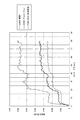
(実施例)
エネルギ吸収部材36aの材質がエネルギ吸収荷重に与える影響を調べるため、エネルギ吸収部材36aに締付杆27aを接触させて潰した長さ(ストローク量)と、吸収荷重と、の関係を、エネルギ吸収部材36aの材質を変更して解析した。(Example)
In order to investigate the influence of the material of the
解析に用いたエネルギ吸収部材36aは、図8及び図9に示したものと同様の構成を有し、各部の寸法は図12に示す通りである。また、エネルギ吸収部材36aと締付杆27aとの上下方向のオーバーラップ量A(図10参照)は、1mmであった。ここで、エネルギ吸収部材36aと締付杆27aとを互いに滑らかに接触させるために、締付杆27aはその中心より下側で、エネルギ吸収部材36aとオーバーラップする。また、エネルギ吸収部材36aの材質としては、日本工業規格 JIS K 6899−1:2006においてPOM−GF25で示される合成樹脂、日本工業規格 JIS H 4000 2014においてA5052で示されるアルミニウム、日本工業規格 JIS H 3100 2012においてC2600で示される黄銅の三種類を用いた。これら三種類の材料の特性は表1に示される。
The

図13に解析結果を示す。何れの材料においても、ストローク量が増えるにしたがって、すなわち切欠き56の左右方向幅が小さくなるにしたがって、吸収荷重が大きくなる傾向は一致する。吸収荷重は、黄銅が最も大きく、アルミニウムが次に大きく、合成樹脂が最も小さい。材料によって吸収荷重に差があるのは、引張り強さ及び伸び等に基づく歪みエネルギの差によるものと考えられる。POM−GF25は、引張り強さが小さいため歪みエネルギが小さいが、黄銅は、引張り強さが大きいため歪みエネルギが大きい。したがって、より大きな吸収荷重が必要な場合には、エネルギ吸収部材36aの材料として、黄銅を採用することが好ましい。また、エネルギ吸収部材36aの材料としては、黄銅と引張り強さや伸びが同等である他の材料を好適に用いることができる。
FIG. 13 shows the analysis result. In any material, the tendency that the absorption load increases as the stroke amount increases, that is, as the width in the left-right direction of the
上述した実施形態では、本発明を、ステアリングホイールの前後位置を調節する為のテレスコピック機構、及び、上下位置を調節する為のチルト機構の両方の機構を備えた構造に対して適用した場合について説明した。但し、本発明を適用する衝撃吸収式ステアリング装置に関しては、テレスコピック機構とチルト機構とのうちの何れか一方の機構のみを備えた構造で実施する事もできる。更には、テレスコピック機構、チルト機構の何れの機構も備えていない、即ち、ステアリングホイールの位置調節装置を備えていない構造で実施する事もできる。例えば、テレスコピック機構のみを備えた構造で実施する場合には、図示の実施形態から、挟持板部25c、25dに形成する通孔を、上下方向長孔26a、26bに代えて、締付杆27aを挿通可能なだけの、単なる円孔とする。又、チルト機構のみを備えた構造で実施する場合には、図示の実施形態から、両被挟持壁部11a、11aに形成する前後方向長孔28、28に代えて、締付杆27aを挿通可能なだけの、単なる円孔とする。更に、位置調節装置を備えない構造で実施する場合には、上下方向長孔26a、26b、前後方向長孔28、28を、何れも単なる円孔とする。この様な位置調節装置を備えない構造で実施する場合に、締付杆をボルトとし、1対の押圧部を、このボルトの頭部、及び、このボルトに螺合したナットとする事もできる。この場合、このナットが一方の押圧部でもあり、且つ、固定手段でもある。
In the above-described embodiments, the case where the present invention is applied to a structure including both a telescopic mechanism for adjusting the front and rear position of the steering wheel and a tilt mechanism for adjusting the vertical position is described. did. However, the shock absorption type steering apparatus to which the present invention is applied can be implemented with a structure including only one of a telescopic mechanism and a tilt mechanism. Furthermore, the present invention can be implemented with a structure that does not include any of the telescopic mechanism and the tilt mechanism, that is, does not include the steering wheel position adjusting device. For example, in the case of carrying out with a structure having only a telescopic mechanism, from the illustrated embodiment, the through holes formed in the
本出願は、2014年11月10日出願の日本特許出願2014−227837に基づくものであり、その内容はここに参照として取り込まれる。 This application is based on the JP Patent application 2014-227837 of an application on November 10, 2014, The content is taken in here as a reference.
1 ステアリングホイール
2 ステアリングギヤユニット
3 入力軸
4 タイロッド
5、5a、5b ステアリングシャフト
6、6a、6b、6c ステアリングコラム
7 自在継手
8 中間シャフト
9 自在継手
10、10a 支持ブラケット
11、11a 被挟持壁部
12 車体側ブラケット
13、13a アウタコラム
14、14a インナコラム
15 電動モータ
16 ハウジング
17、17a 支持管
18 天板
19a、19b 側板
20 結合板部
21、21a 切欠き
22、22a カプセル
23 通孔
25a、25b、25c、25d 挟持板部
26、26a、26b 上下方向長孔
27、27a 締付杆
28 前後方向長孔
29 鍔部
30、30a 駆動側カム
31、31a 被駆動側カム
32、32a カム装置
33、33a 調節レバー
34 係止部
35、35a 釣合ばね
36、36a エネルギ吸収部材
37 車体
38 支持ピン
39 保持ケース
40 電動式パワーステアリング装置
41 ハウジング
42 ブリッジ
43 スリット
44 アウタシャフト
45 インナシャフト
46 取付板部
47、47a チルトスペーサ
48 テレスコスペーサ
49 ワッシャ
50 スラスト軸受
51 ナット
52 取付孔
53 フック部
54 ガイド部
55 吸収部
56 切欠き
56a 第1一定幅部
56b 第1先細部
56c 第2一定幅部
56d 第2先細部
57 ストッパ部
60 スペーサー
65 復位ばね
70 多板プレートDESCRIPTION OF SYMBOLS 1 Steering wheel 2 Steering gear unit 3 Input shaft 4 Tie rod 5, 5a, 5b Steering shaft 6, 6a, 6b, 6c Steering column 7 Universal joint 8 Intermediate shaft 9 Universal joint 10, 10a Support bracket 11, 11a Clamping wall part 12 Car body side bracket 13, 13a Outer column 14, 14a Inner column 15 Electric motor 16 Housing 17, 17a Support pipe 18 Top plate 19a, 19b Side plate 20 Coupling plate part 21, 21a Notch 22, 22a Capsule 23 Through hole 25a, 25b, 25c, 25d Clamping plate portion 26, 26a, 26b Longitudinal direction long hole 27, 27a Clamping rod 28 Longitudinal direction long hole 29 Ling portion 30, 30a Drive side cam 31, 31a Driven side cam 32, 32a Cam device 33, 33a Adjustment lever 34 Locking portion 35, 35a Balance spring 36, 36a Energy absorbing member 37 Car body 38 Support pin 39 Holding case 40 Electric power steering device 41 Housing 42 Bridge 43 Slit 44 Outer shaft 45 Inner shaft 46 Mounting plate portion 47, 47a Tilt spacer 48 Telescopic spacer 49 Washer 50 Thrust bearing 51 Nut 52 Mounting hole 53 Hook part 54 Guide part 55 Absorbing part 56 Notch 56a First constant width part 56b First tapered part 56c Second constant width part 56d Second tapered part 57 Stopper part 60 Spacer 65 Reverse spring 70 Multi-plate
Claims (11)
前記インナコラムの後部に外嵌され、前記インナコラムとの嵌合部である前部に軸方向に設けられたスリットによって前記前部の直径を拡縮可能としたアウタコラムと、
アウタシャフトとインナシャフトとを全長を収縮可能に組み合わせて成り、前記インナコラムと前記アウタコラムとから成るステアリングコラムの内径側に回転自在に支持され、後端部を前記アウタコラムの後端開口よりも後方に突出させたステアリングシャフトと、
前記ステアリングシャフトに支持されたステアリングホイールと、
前記アウタコラムの前部で前記スリットを左右両側から挟む位置に設けられた1対の被挟持壁部と、
前記1対の被挟持壁部の互いに整合する位置に形成された1対の前後方向長孔と、
左右1対の挟持板部及び前記1対の挟持板部を車体に対して支持する取付板部を有する支持ブラケットであって、前記取付板部が、二次衝突時に加わる衝撃荷重に基づいて前方への脱落を可能に、車体に対して支持される、支持ブラケットと、
前記1対の挟持板部の前記1対の前後方向長孔に整合する部分に形成された1対の上下方向長孔と、
前記1対の前後方向長孔と前記1対の上下方向長孔とを挿通する締付杆と、
前記締付杆の両端部に設けられた1対の押圧部の間隔を拡縮し、前記間隔の収縮時に前記アウタコラムの前記前部の前記直径を縮め、前記アウタコラムの前部内周面と前記インナコラムの後部外周面とを摩擦係合させる固定手段と、
二次衝突時に前記ステアリングホイールから前記アウタコラムに加えられた衝撃エネルギを吸収するエネルギ吸収部材と、
を備えた衝撃吸収式ステアリング装置に於いて、
前記エネルギ吸収部材は、前記インナコラムの外周面に固定され、前後方向に延びて前記アウタコラムの前記スリットの内側に入り込んでおり、
二次衝突時に前記締付杆が前記アウタコラムと共に前方へ変位することによって、前記エネルギ吸収部材は、上下方向から前記締付杆及び前記インナコラムに拘束されながら、前記締付杆に潰されて衝撃吸収荷重を発生する、衝撃吸収式ステアリング装置。An inner column arranged on the front side with the front-rear position regulated,
An outer column that is externally fitted to the rear part of the inner column, and that allows the diameter of the front part to be expanded and contracted by a slit provided in the axial direction at the front part that is a fitting part with the inner column;
The outer shaft and the inner shaft are combined in such a manner that the entire length can be contracted, and is rotatably supported on the inner diameter side of the steering column including the inner column and the outer column, and the rear end portion is opened from the rear end opening of the outer column. And a steering shaft that protrudes backward,
A steering wheel supported by the steering shaft;
A pair of sandwiched wall portions provided at positions where the slit is sandwiched from the left and right sides at the front portion of the outer column;
A pair of longitudinal slots formed at positions of the pair of sandwiched wall portions aligned with each other;
A support bracket having a pair of left and right sandwiching plate portions and a mounting plate portion that supports the pair of sandwiching plate portions with respect to a vehicle body, wherein the mounting plate portion moves forward based on an impact load applied during a secondary collision. A support bracket that is supported against the vehicle body so that it can be dropped off,
A pair of vertical slots formed in a portion aligned with the pair of longitudinal slots in the pair of clamping plates;
A clamping rod for inserting the pair of longitudinal slots and the pair of vertical slots;
The distance between the pair of pressing portions provided at both ends of the fastening rod is expanded and contracted, the diameter of the front portion of the outer column is contracted when the interval is contracted, and the front inner peripheral surface of the outer column and the Fixing means for frictionally engaging the rear outer peripheral surface of the inner column;
An energy absorbing member that absorbs impact energy applied to the outer column from the steering wheel during a secondary collision;
In the shock absorption type steering device equipped with
The energy absorbing member is fixed to the outer peripheral surface of the inner column, extends in the front-rear direction, and enters the inside of the slit of the outer column,
When the clamping rod is displaced forward together with the outer column at the time of a secondary collision, the energy absorbing member is crushed by the clamping rod while being restrained by the clamping rod and the inner column from above and below. Shock absorbing steering device that generates shock absorbing load.
前記エネルギ吸収部材は、前記取付孔に係合するガイド部と、前記インナコラムの内面に引っ掛かり、前記エネルギ吸収部材の前記取付孔からの脱落を防止するフック部と、を有する、請求項1〜5の何れか1項に記載した衝撃吸収式ステアリング装置。A mounting hole for mounting the energy absorbing member is formed on the outer peripheral surface of the inner column,
The said energy absorption member has a guide part engaged with the said attachment hole, and a hook part which hooks on the inner surface of the said inner column, and prevents the fall of the said energy absorption member from the said attachment hole. 6. The shock absorbing steering device according to any one of 5 above.
二次衝突に伴って前方へ変位する前記アウタコラムの前記ブリッジは、前記エネルギ吸収部材をガイドしながら変位する、請求項1〜8の何れか1項に記載した衝撃吸収式ステアリング装置。At the front end of the outer column, a bridge through which the energy absorbing member is inserted is provided,
The shock absorbing steering apparatus according to any one of claims 1 to 8, wherein the bridge of the outer column that is displaced forward in accordance with a secondary collision is displaced while guiding the energy absorbing member.
Applications Claiming Priority (3)
| Application Number | Priority Date | Filing Date | Title |
|---|---|---|---|
| JP2014227837 | 2014-11-10 | ||
| JP2014227837 | 2014-11-10 | ||
| PCT/JP2015/081482 WO2016076266A1 (en) | 2014-11-10 | 2015-11-09 | Shock absorbing steering device |
Publications (2)
| Publication Number | Publication Date |
|---|---|
| JP5950072B1 true JP5950072B1 (en) | 2016-07-13 |
| JPWO2016076266A1 JPWO2016076266A1 (en) | 2017-04-27 |
Family
ID=55954351
Family Applications (1)
| Application Number | Title | Priority Date | Filing Date |
|---|---|---|---|
| JP2016514197A Active JP5950072B1 (en) | 2014-11-10 | 2015-11-09 | Shock absorbing steering device |
Country Status (5)
| Country | Link |
|---|---|
| US (1) | US9821833B2 (en) |
| EP (1) | EP3095671B1 (en) |
| JP (1) | JP5950072B1 (en) |
| CN (1) | CN107074267B (en) |
| WO (1) | WO2016076266A1 (en) |
Families Citing this family (8)
| Publication number | Priority date | Publication date | Assignee | Title |
|---|---|---|---|---|
| EP3225505B1 (en) * | 2015-01-14 | 2018-12-26 | NSK Ltd. | Steering device |
| DE102015216715A1 (en) * | 2015-09-01 | 2017-03-02 | Thyssenkrupp Ag | Adjustable steering column for motor vehicles with energy absorber for vehicle crash |
| JP6759746B2 (en) * | 2016-06-20 | 2020-09-23 | 日本精工株式会社 | Steering device |
| KR102350529B1 (en) * | 2017-09-27 | 2022-01-13 | 남양넥스모 주식회사 | Apparatus for suction impact of steering column |
| JP6976889B2 (en) * | 2018-03-16 | 2021-12-08 | 富士機工株式会社 | Steering column device |
| US11722035B2 (en) * | 2018-09-12 | 2023-08-08 | Nsk Ltd. | Electric motor with reverse input cutoff clutch |
| US11225281B2 (en) * | 2018-12-21 | 2022-01-18 | Steering Solutions Ip Holding Corporation | Steering column assembly |
| WO2021193449A1 (en) * | 2020-03-27 | 2021-09-30 | 株式会社山田製作所 | Steering device |
Citations (3)
| Publication number | Priority date | Publication date | Assignee | Title |
|---|---|---|---|---|
| JP2008280002A (en) * | 2007-05-14 | 2008-11-20 | Jtekt Corp | Impact absorbing steering device |
| JP2009208506A (en) * | 2008-02-29 | 2009-09-17 | Nsk Ltd | Impact-absorption type steering device |
| JP2011093444A (en) * | 2009-10-30 | 2011-05-12 | Nsk Ltd | Shock absorbing type steering device |
Family Cites Families (9)
| Publication number | Priority date | Publication date | Assignee | Title |
|---|---|---|---|---|
| JPH0723099B2 (en) | 1986-08-14 | 1995-03-15 | 日本精工株式会社 | Energy absorption type steering device |
| JPH0712215Y2 (en) * | 1988-06-17 | 1995-03-22 | 日本精工株式会社 | Shock absorption steering device |
| JPH0575057U (en) | 1992-03-13 | 1993-10-12 | 日本精工株式会社 | Shock absorption type steering column device |
| FR2747357B1 (en) | 1996-04-12 | 1998-07-10 | Ecia Equip Composants Ind Auto | SHOCK ENERGY ABSORPTION STEERING COLUMN ASSEMBLY, PARTICULARLY FOR MOTOR VEHICLE |
| JP2005075250A (en) * | 2003-09-03 | 2005-03-24 | Nsk Ltd | Shock absorbing type steering column device with telescopic mechanism |
| EP2439126B1 (en) * | 2010-08-06 | 2015-08-12 | NSK Ltd. | Shock-absorbing steering device |
| EP2738064B1 (en) * | 2012-03-06 | 2018-04-18 | NSK Ltd. | Impact absorbing steering device |
| CN203496979U (en) * | 2013-08-15 | 2014-03-26 | 上海汽车集团股份有限公司 | Steering pipe column with function of reducing harm to driver |
| DE102014000069A1 (en) | 2014-01-09 | 2015-07-09 | Thyssenkrupp Presta Ag | Crash system made of fiber composite material for energy absorption |
-
2015
- 2015-11-09 EP EP15859281.6A patent/EP3095671B1/en active Active
- 2015-11-09 CN CN201580060594.8A patent/CN107074267B/en active Active
- 2015-11-09 US US15/108,684 patent/US9821833B2/en active Active
- 2015-11-09 JP JP2016514197A patent/JP5950072B1/en active Active
- 2015-11-09 WO PCT/JP2015/081482 patent/WO2016076266A1/en active Application Filing
Patent Citations (3)
| Publication number | Priority date | Publication date | Assignee | Title |
|---|---|---|---|---|
| JP2008280002A (en) * | 2007-05-14 | 2008-11-20 | Jtekt Corp | Impact absorbing steering device |
| JP2009208506A (en) * | 2008-02-29 | 2009-09-17 | Nsk Ltd | Impact-absorption type steering device |
| JP2011093444A (en) * | 2009-10-30 | 2011-05-12 | Nsk Ltd | Shock absorbing type steering device |
Also Published As
| Publication number | Publication date |
|---|---|
| CN107074267B (en) | 2018-05-18 |
| US9821833B2 (en) | 2017-11-21 |
| EP3095671A1 (en) | 2016-11-23 |
| US20160347349A1 (en) | 2016-12-01 |
| CN107074267A (en) | 2017-08-18 |
| JPWO2016076266A1 (en) | 2017-04-27 |
| WO2016076266A1 (en) | 2016-05-19 |
| EP3095671B1 (en) | 2019-02-20 |
| EP3095671A4 (en) | 2017-10-25 |
Similar Documents
| Publication | Publication Date | Title |
|---|---|---|
| JP5950072B1 (en) | Shock absorbing steering device | |
| JP5293825B2 (en) | Shock absorbing steering device | |
| JP5293824B2 (en) | Shock absorbing steering device | |
| EP2722253B1 (en) | Steering device | |
| JP6028872B2 (en) | Steering device | |
| JP5327164B2 (en) | Shock absorbing steering device with electric power steering device | |
| US10093341B2 (en) | Steering device | |
| JPWO2011158787A1 (en) | Steering column support device | |
| JP5076673B2 (en) | Steering device | |
| JP5267528B2 (en) | Shock absorbing steering device | |
| JP5229279B2 (en) | Shock absorbing steering device | |
| JP6020186B2 (en) | Steering column support device | |
| JP2009120133A (en) | Steering device | |
| KR20190004442A (en) | Mounting unit for sub frame of vehicles | |
| JP2014136501A (en) | Steering column support device | |
| JP6409551B2 (en) | Vehicle steering device | |
| JP2016002771A (en) | Tilt-type steering device | |
| JP6098745B2 (en) | Steering device | |
| JP5796553B2 (en) | Tilt-type steering device | |
| JP6503864B2 (en) | Steering device | |
| JP5327203B2 (en) | Steering column support device | |
| JP2016120785A (en) | Electric power steering device | |
| JP2017222287A (en) | Steering device |
Legal Events
| Date | Code | Title | Description |
|---|---|---|---|
| AA64 | Notification of invalidation of claim of internal priority (with term) |
Free format text: JAPANESE INTERMEDIATE CODE: A241764 Effective date: 20160412 |
|
| A521 | Request for written amendment filed |
Free format text: JAPANESE INTERMEDIATE CODE: A523 Effective date: 20160422 |
|
| TRDD | Decision of grant or rejection written | ||
| A975 | Report on accelerated examination |
Free format text: JAPANESE INTERMEDIATE CODE: A971005 Effective date: 20160427 |
|
| A01 | Written decision to grant a patent or to grant a registration (utility model) |
Free format text: JAPANESE INTERMEDIATE CODE: A01 Effective date: 20160510 |
|
| A61 | First payment of annual fees (during grant procedure) |
Free format text: JAPANESE INTERMEDIATE CODE: A61 Effective date: 20160523 |
|
| R150 | Certificate of patent or registration of utility model |
Ref document number: 5950072 Country of ref document: JP Free format text: JAPANESE INTERMEDIATE CODE: R150 |
|
| R250 | Receipt of annual fees |
Free format text: JAPANESE INTERMEDIATE CODE: R250 |