JP5938099B2 - Base station, user equipment and method in them for assignment of control timing configuration in multiple cell communication network - Google Patents
Base station, user equipment and method in them for assignment of control timing configuration in multiple cell communication network Download PDFInfo
- Publication number
- JP5938099B2 JP5938099B2 JP2014524966A JP2014524966A JP5938099B2 JP 5938099 B2 JP5938099 B2 JP 5938099B2 JP 2014524966 A JP2014524966 A JP 2014524966A JP 2014524966 A JP2014524966 A JP 2014524966A JP 5938099 B2 JP5938099 B2 JP 5938099B2
- Authority
- JP
- Japan
- Prior art keywords
- downlink
- configuration number
- control timing
- timing
- configuration
- Prior art date
- Legal status (The legal status is an assumption and is not a legal conclusion. Google has not performed a legal analysis and makes no representation as to the accuracy of the status listed.)
- Active
Links
Images


Classifications
-
- H—ELECTRICITY
- H04—ELECTRIC COMMUNICATION TECHNIQUE
- H04L—TRANSMISSION OF DIGITAL INFORMATION, e.g. TELEGRAPHIC COMMUNICATION
- H04L5/00—Arrangements affording multiple use of the transmission path
- H04L5/14—Two-way operation using the same type of signal, i.e. duplex
-
- H—ELECTRICITY
- H04—ELECTRIC COMMUNICATION TECHNIQUE
- H04B—TRANSMISSION
- H04B7/00—Radio transmission systems, i.e. using radiation field
- H04B7/24—Radio transmission systems, i.e. using radiation field for communication between two or more posts
- H04B7/26—Radio transmission systems, i.e. using radiation field for communication between two or more posts at least one of which is mobile
- H04B7/2612—Arrangements for wireless medium access control, e.g. by allocating physical layer transmission capacity
-
- H—ELECTRICITY
- H04—ELECTRIC COMMUNICATION TECHNIQUE
- H04L—TRANSMISSION OF DIGITAL INFORMATION, e.g. TELEGRAPHIC COMMUNICATION
- H04L1/00—Arrangements for detecting or preventing errors in the information received
- H04L1/12—Arrangements for detecting or preventing errors in the information received by using return channel
- H04L1/16—Arrangements for detecting or preventing errors in the information received by using return channel in which the return channel carries supervisory signals, e.g. repetition request signals
- H04L1/18—Automatic repetition systems, e.g. Van Duuren systems
- H04L1/1829—Arrangements specially adapted for the receiver end
- H04L1/1861—Physical mapping arrangements
-
- H—ELECTRICITY
- H04—ELECTRIC COMMUNICATION TECHNIQUE
- H04J—MULTIPLEX COMMUNICATION
- H04J11/00—Orthogonal multiplex systems, e.g. using WALSH codes
-
- H—ELECTRICITY
- H04—ELECTRIC COMMUNICATION TECHNIQUE
- H04J—MULTIPLEX COMMUNICATION
- H04J11/00—Orthogonal multiplex systems, e.g. using WALSH codes
- H04J11/0023—Interference mitigation or co-ordination
-
- H—ELECTRICITY
- H04—ELECTRIC COMMUNICATION TECHNIQUE
- H04L—TRANSMISSION OF DIGITAL INFORMATION, e.g. TELEGRAPHIC COMMUNICATION
- H04L1/00—Arrangements for detecting or preventing errors in the information received
- H04L1/12—Arrangements for detecting or preventing errors in the information received by using return channel
- H04L1/16—Arrangements for detecting or preventing errors in the information received by using return channel in which the return channel carries supervisory signals, e.g. repetition request signals
- H04L1/18—Automatic repetition systems, e.g. Van Duuren systems
- H04L1/1812—Hybrid protocols; Hybrid automatic repeat request [HARQ]
-
- H—ELECTRICITY
- H04—ELECTRIC COMMUNICATION TECHNIQUE
- H04L—TRANSMISSION OF DIGITAL INFORMATION, e.g. TELEGRAPHIC COMMUNICATION
- H04L5/00—Arrangements affording multiple use of the transmission path
- H04L5/0001—Arrangements for dividing the transmission path
- H04L5/0003—Two-dimensional division
- H04L5/0005—Time-frequency
- H04L5/0007—Time-frequency the frequencies being orthogonal, e.g. OFDM(A) or DMT
- H04L5/001—Time-frequency the frequencies being orthogonal, e.g. OFDM(A) or DMT the frequencies being arranged in component carriers
-
- H—ELECTRICITY
- H04—ELECTRIC COMMUNICATION TECHNIQUE
- H04L—TRANSMISSION OF DIGITAL INFORMATION, e.g. TELEGRAPHIC COMMUNICATION
- H04L5/00—Arrangements affording multiple use of the transmission path
- H04L5/003—Arrangements for allocating sub-channels of the transmission path
- H04L5/0053—Allocation of signalling, i.e. of overhead other than pilot signals
- H04L5/0055—Physical resource allocation for ACK/NACK
-
- H—ELECTRICITY
- H04—ELECTRIC COMMUNICATION TECHNIQUE
- H04L—TRANSMISSION OF DIGITAL INFORMATION, e.g. TELEGRAPHIC COMMUNICATION
- H04L5/00—Arrangements affording multiple use of the transmission path
- H04L5/14—Two-way operation using the same type of signal, i.e. duplex
- H04L5/1469—Two-way operation using the same type of signal, i.e. duplex using time-sharing
-
- H—ELECTRICITY
- H04—ELECTRIC COMMUNICATION TECHNIQUE
- H04L—TRANSMISSION OF DIGITAL INFORMATION, e.g. TELEGRAPHIC COMMUNICATION
- H04L5/00—Arrangements affording multiple use of the transmission path
- H04L5/14—Two-way operation using the same type of signal, i.e. duplex
- H04L5/16—Half-duplex systems; Simplex/duplex switching; Transmission of break signals non-automatically inverting the direction of transmission
-
- H—ELECTRICITY
- H04—ELECTRIC COMMUNICATION TECHNIQUE
- H04W—WIRELESS COMMUNICATION NETWORKS
- H04W72/00—Local resource management
- H04W72/04—Wireless resource allocation
- H04W72/044—Wireless resource allocation based on the type of the allocated resource
- H04W72/0446—Resources in time domain, e.g. slots or frames
-
- H—ELECTRICITY
- H04—ELECTRIC COMMUNICATION TECHNIQUE
- H04W—WIRELESS COMMUNICATION NETWORKS
- H04W72/00—Local resource management
- H04W72/20—Control channels or signalling for resource management
- H04W72/21—Control channels or signalling for resource management in the uplink direction of a wireless link, i.e. towards the network
-
- H—ELECTRICITY
- H04—ELECTRIC COMMUNICATION TECHNIQUE
- H04W—WIRELESS COMMUNICATION NETWORKS
- H04W72/00—Local resource management
- H04W72/20—Control channels or signalling for resource management
- H04W72/23—Control channels or signalling for resource management in the downlink direction of a wireless link, i.e. towards a terminal
-
- H—ELECTRICITY
- H04—ELECTRIC COMMUNICATION TECHNIQUE
- H04W—WIRELESS COMMUNICATION NETWORKS
- H04W76/00—Connection management
- H04W76/20—Manipulation of established connections
- H04W76/27—Transitions between radio resource control [RRC] states
-
- H—ELECTRICITY
- H04—ELECTRIC COMMUNICATION TECHNIQUE
- H04W—WIRELESS COMMUNICATION NETWORKS
- H04W88/00—Devices specially adapted for wireless communication networks, e.g. terminals, base stations or access point devices
- H04W88/02—Terminal devices
-
- H—ELECTRICITY
- H04—ELECTRIC COMMUNICATION TECHNIQUE
- H04W—WIRELESS COMMUNICATION NETWORKS
- H04W88/00—Devices specially adapted for wireless communication networks, e.g. terminals, base stations or access point devices
- H04W88/08—Access point devices
Landscapes
- Engineering & Computer Science (AREA)
- Signal Processing (AREA)
- Computer Networks & Wireless Communication (AREA)
- Mobile Radio Communication Systems (AREA)
Description
例示的実施形態は、マルチプルセル通信ネットワークにおける、制御タイミングについての用の制御タイミングコンフィギュレーション番号の割当て及び実装のための基地局、ユーザ装置及びそれらにおける方法を対象とする。 Exemplary embodiments are directed to base stations, user equipment and methods thereof for assigning and implementing control timing configuration numbers for control timing in a multiple cell communication network.
LTEシステム
LTE(Long Term Evolution)は、下りリンク方向でOFDM(Orthogonal Frequency Division Multiplexing:直交周波数分割多重)を、上りリンク方向でDFT(Discrete Fourier Transform:離散フーリエ変換)拡散OFDMを用いる。したがって、基本的なLTE下りリンク物理リソースは、図1に示すような時間−周波数グリッドと考えることができ、この場合、各リソースエレメントは、1つのOFDMシンボル区間における1つのOFDMサブキャリアに対応する。時間領域では、図2に示すように、LTE下りリンク送信は、10msの無線フレームに分かれていて、個々の無線フレームが、Tサブフレーム=1msの長さの10個の同サイズのサブフレームで構成されうる。
The LTE system LTE (Long Term Evolution) uses OFDM (Orthogonal Frequency Division Multiplexing) in the downlink direction and DFT (Discrete Fourier Transform) spread OFDM in the uplink direction. Accordingly, the basic LTE downlink physical resource can be considered as a time-frequency grid as shown in FIG. 1, where each resource element corresponds to one OFDM subcarrier in one OFDM symbol period. . In the time domain, as shown in FIG. 2, the LTE downlink transmission is divided into 10 ms radio frames, and each radio frame is 10 subframes of the same size with a length of T subframe = 1 ms. Can be configured.
また、LTEにおけるリソース割当ては、典型的には、リソースブロックの観点で説明され、1つのリソースブロックは、時間領域における1スロット(0.5ms)、周波数領域における12のサブキャリアに対応する。リソースブロックには、周波数領域において、システム帯域幅の一方の端部から0で始まる番号が付けられている。 Also, resource allocation in LTE is typically described in terms of resource blocks, and one resource block corresponds to one slot (0.5 ms) in the time domain and 12 subcarriers in the frequency domain. Resource blocks are numbered starting with 0 from one end of the system bandwidth in the frequency domain.
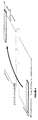
下りリンク送信は、動的にスケジューリングされ、すなわち、基地局は、現在の下りリンクサブフレームで、どのユーザ装置に対してデータが送信されるのか、及び、どのリソースブロック上でデータが送信されるのかについての制御情報を、各サブフレーム内で送信する。この制御シグナリングは、典型的には、各サブフレーム内の最初の1、2、3、または4番目のOFDMシンボルで送信される。図3に、制御のための3つのOFDMシンボルを有する下りリンクシステムを示す。動的なスケジューリング情報が、制御領域で送信されるPDCCH(Physical Downlink Control Channel:物理下りリンク制御チャネル)を介してユーザ装置へ伝達される。PDCCHの復号が成功した後、ユーザ装置は、LTE仕様で規定される所定のタイミングに従ってPDSCH(Physical Downlink Shared Channel:物理下りリンク共有チャネル)の受信またはPUSCH(Physical Uplink Shared Channel:物理上りリンク共有チャネル)の送信を行うことになっている。 Downlink transmissions are dynamically scheduled, ie, the base station transmits data to which user equipment and on which resource block the data is transmitted in the current downlink subframe. The control information about whether or not is transmitted in each subframe. This control signaling is typically transmitted in the first 1, 2, 3, or 4th OFDM symbol in each subframe. FIG. 3 shows a downlink system having three OFDM symbols for control. Dynamic scheduling information is transmitted to the user equipment via a PDCCH (Physical Downlink Control Channel) transmitted in the control region. After successful decoding of the PDCCH, the user equipment receives PDSCH (Physical Downlink Shared Channel) or PUSCH (Physical Uplink Shared Channel) according to a predetermined timing defined in LTE specifications. ) Is supposed to be sent.
LTEは、HARQ(Hybrid-Automatic Repeat Request:ハイブリッド自動再送要求)を使用しており、ユーザ装置は、サブフレーム内の下りリンクデータを受信した後、それを復号することを試行して、PUCCH(Physical Uplink Control CHannel:物理上りリンク制御チャネル)を介してACK(Acknowledge:肯定応答)を送信することで復号が成功したことを、あるいはNACK(Non-Acknowledgement:否定応答)を送信することで復号が成功しなかったことを、基地局へ報告する。復号の試行が失敗した場合、基地局は、誤りが生じたデータを再送信することができる。同様に、基地局は、PHICH(Physical Hybrid ARQ Indicator CHannel:物理ハイブリッドARQインジケータ・チャネル)を介してACKを送信することでPUSCHの復号が成功したことを、あるいはNACKを送信することで復号が成功しなかったことを、UEに知らせることができる。 LTE uses HARQ (Hybrid-Automatic Repeat Request), and after receiving the downlink data in the subframe, the user equipment tries to decode the downlink data, and PUCCH ( Decoding is successful by sending ACK (Acknowledge: Acknowledge) via Physical Uplink Control CHannel, or decoding by sending NACK (Non-Acknowledgement) Report to the base station that it was not successful. If the decoding attempt fails, the base station can retransmit the erroneous data. Similarly, the base station has successfully decoded PUSCH by transmitting ACK via PHICH (Physical Hybrid ARQ Indicator CHannel), or has successfully decoded by transmitting NACK. The UE can be notified of the failure.
ユーザ装置から基地局への上りリンク制御シグナリングは、(1)受信された下りリンクデータについてのHARQ確認応答と、(2)下りリンクのスケジューリング用の支援として用いられる、下りリンクのチャネル状態に関するユーザ装置の報告と、(3)モバイル・ユーザ装置が上りリンクのデータ送信用の上りリンクリソースを必要としていることを示すスケジューリング要求と、のうちの少なくとも1つを含んでいてもよい。 Uplink control signaling from the user equipment to the base station includes (1) HARQ confirmation response for received downlink data, and (2) user regarding downlink channel state used as support for downlink scheduling. It may include at least one of a device report and (3) a scheduling request indicating that the mobile user device needs an uplink resource for uplink data transmission.
モバイル・ユーザ装置にデータ送信用の上りリンクリソースがまだ割り当てられていない場合、チャネルステータス報告、HARQ確認応答、スケジューリング要求のようなL1/L2制御情報が、上りリンクリソースで、例えば、リリース8(Rel−8)PUCCH上の上りリンクL1/L2制御のために特に割り当てられたリソースブロックで、送信される。図4に示すように、これらの上りリンクリソースは、利用可能な送信帯域幅全体のうちの端部に位置している。個々のそのような上りリンクリソースは、上りリンクサブフレームの2つのスロットそれぞれの中に12個の「サブキャリア」(1つのリソースブロック)を含んでいる。周波数タイバーシチを可能にするため、これらの周波数リソースは、矢印で示すように、スロット境界線上で周波数ホッピングされる。すなわち、1つの「リソース」は、サブフレームの第1のスロットの範囲内のスペクトルの上部に12個のサブキャリアを含んでおり、かつ、サブフレームの第2のスロットの期間にスペクトルの下部に同サイズのリソースを含んでおり、逆もまた同様である。もっと多くのリソースが上りリンクL1/L2制御シグナリング用として必要である場合、例えば、多数のユーザをサポートしていて送信帯域幅全体が非常に広い場合、以前割り当てられたリソースブロックの隣に追加のリソースブロックを割り当てることができる。 If uplink resources for data transmission are not yet allocated to the mobile user equipment, L1 / L2 control information such as channel status report, HARQ confirmation response, scheduling request is uplink resources, for example, release 8 ( Rel-8) transmitted in resource blocks specifically allocated for uplink L1 / L2 control on PUCCH. As shown in FIG. 4, these uplink resources are located at the end of the entire available transmission bandwidth. Each such uplink resource includes 12 “subcarriers” (one resource block) in each of the two slots of the uplink subframe. In order to enable frequency diversity, these frequency resources are frequency hopped on slot boundaries as indicated by the arrows. That is, one “resource” contains 12 subcarriers at the top of the spectrum within the first slot of the subframe, and is at the bottom of the spectrum during the second slot of the subframe. It contains resources of the same size and vice versa. If more resources are needed for uplink L1 / L2 control signaling, e.g. when supporting a large number of users and the overall transmission bandwidth is very wide, additional resources are added next to the previously allocated resource block Resource blocks can be allocated.
キャリア・アグリゲーション
近年、LTEリリース10(Rel−10)標準規格が標準化され、20MHzを上回る帯域幅をサポートしている。LTEリリース10に関する1つの要求条件は、LTEリリース8との下位互換性を保証することである。これには、スペクトルの互換性も含まれうる。このことは、LTEリリース8のユーザ装置には、20MHzより広いLTEリリース10のキャリアが複数のLTEキャリアのように見えるということを意味するであろう。そのような個々のキャリアは、コンポーネントキャリア(CC)と称されうる。特に、LTEリリース10展開の初期には、多数の旧式のLTEユーザ装置に比べてLTEリリース10対応のユーザ装置は少数であろうと予測できる。したがって、旧式のユーザ装置にも広いキャリアの効率的な使用を保証すること、すなわち、旧式のユーザ装置が、広帯域LTEリリース10キャリアの全ての部分においてスケジューリングされうるようなキャリアを実現できることが有益であろう。これを得る直接的な方法は、キャリア・アグリゲーション(CA)によることであろう。CAとは、LTEリリース10のユーザ装置が複数のCCを受信でき、CCはリリース8のキャリアと同じ構造を有するか、または少なくとも、有する可能性を有することを意味する。図5にCAを示す。
Carrier Aggregation In recent years, the LTE Release 10 (Rel-10) standard has been standardized and supports bandwidths in excess of 20 MHz. One requirement for
アグリゲーションされるCCの数及び個別のCCの帯域幅は、上りリンクと下りリンクとで異なっていてもよい。対称のコンフィギュレーション(configuration)とは、下りリンクと上りリンクとでCCの数が同じである場合のことを言い、非対称のコンフィギュレーションとは、下りリンクと上りリンクとでCCの数が異なる場合のことを言う。注意すべきことは、セル内でコンフィギュレーションされるCCの数が、ユーザ装置から見たCCの数とは異なる場合があることである。ネットワークが、同じ数の上りリンクCC及び下りリンクCCでコンフィギュレーションされていても、ユーザ装置は、例えば、上りリンクCCより多くの下りリンクCCをサポートする場合がある。 The number of CCs to be aggregated and the bandwidth of individual CCs may be different between the uplink and the downlink. A symmetric configuration means a case where the number of CCs is the same between the downlink and the uplink, and an asymmetric configuration means a case where the number of CCs differs between the downlink and the uplink. Say that. It should be noted that the number of CCs configured in a cell may be different from the number of CCs seen from the user equipment. Even if the network is configured with the same number of uplink CCs and downlink CCs, the user equipment may support more downlink CCs than uplink CCs, for example.
最初のアクセスの間、LTEリリース10のユーザ装置は、LTEリリース8のユーザ装置と同様に動作する。ネットワークへの接続が成功すると、ユーザ装置は、自分の能力とネットワークとに依存して、上りリンクと下りリンクとについて追加のCCを用いてコンフィギュレーションされうる。RRC(Radio Resource Control:無線リソース制御)に基づいてコンフィギュレーションが行なわれる。RRCシグナリングの大量のシグナリングとやや遅い速度とに起因して、たとえ現時点で全てのCCが使用されていなくても、ユーザ装置が複数のCCを用いてコンフィギュレーションされうることが想定される。ユーザ装置が、複数のCC上でコンフィギュレーションされる場合、これは、ユーザ装置が、PDCCHとPDSCHとについて全ての下りリンクCCを監視する必要があるということを意味するであろう。これは、より広い受信機帯域幅、より高速のサンプリングレートなどを意味し、結果として電力消費量が増加する。
During initial access,
上記の諸問題を軽減させるため、LTEリリース10は、コンフィギュレーションに加えてCCの有効化(activation)をサポートする。ユーザ装置は、PDCCH及びPDSCHについて、コンフィギュレーションされて有効化されたCCだけを監視する。有効化は、RRCシグナリングよりも高速のMAC(Medium Access Control:媒体アクセス制御)制御エレメントに基づいて行なわれるため、有効化/無効化(de-activation)は、現在のデータレートの必要性を満たすのに必要なCCの数に従うことができる。複数のCCが、大きいデータ量の到着に応じて有効化され、データ送信用に使用され、必要ない場合に無効化される。下りリンクプライマリCC(DL PCC:Downlink (DL) Primary CC)という1つのCCだけを除いて全てのCCが無効化されてもよい。したがって、有効化によって、複数のCCをコンフィギュレーションするがそれらを有効化するのは必要な場合に限られる可能性がもたらされる。ほとんどの時間、ユーザ装置は、1つ若しくは非常に少ない数のCCを有効化させるであろうから、結果として、受信帯域幅及びバッテリの消費が減少する。
To alleviate the above problems,
CCのスケジューリングは、PDCCH上で下りリンク割当てを介して行われてうる。PDCCH上の制御情報は、DCI(Downlink Control Information:下りリンク制御情報)メッセージとしてフォーマットされうる。リリース8では、ユーザ装置は、1つの下りリンクCC及び1つの上りリンクCCだけを用いて動作しうる。下りリンク割当てと、上りリンクグラントと、対応する下りリンクCC及び上りリンクCCとの間の関連は、それ故に明確である。リリース10では、2つのモードのCAが区別されるべきである。第1のモードは、マルチプル・リリース8・CCの動作に非常に良く似ており、CC上で送信されるDCIメッセージ内に含まれる下りリンク割当てまたは上りリンクグラントは、下りリンクCC自体にとって有効か、あるいは(セル固有またはユーザ装置固有のリンクを介して)関連する上りリンクCCにとって有効かのいずれかである。第2の動作モードでは、DCIメッセージがCIF(Carrier Indicator Field:キャリア・インジケータ・フィールド)を用いて補強される。CIF付きの下りリンク割当てを含むDCIは、CIFによって示されるその下りリンクCCについて有効であり、CIF付きの上りリンクグラントを含むDCIは、示される上りリンクCCについて有効である。
CC scheduling may be performed via downlink assignment on the PDCCH. Control information on the PDCCH can be formatted as a DCI (Downlink Control Information) message. In
下りリンク割当て用のDCIメッセージは、特に、リソースブロック割当て、変調及び符号化方式関連パラメータ、HARQ冗長性バージョンなどを含んでいる。また、実際の下りリンク送信に関係するこれらのパラメータに加えて、下りリンク割当て用のほとんどのDCIフォーマットは、TPC(Transmit Power Control:送信電力制御)コマンド用のビットフィールドも含んでいる。HARQフィードバックを送信するのに用いられる、対応するPUCCHの上りリンク電力制御動作を制御するために、これらのTPCコマンドが用いられる。 The DCI message for downlink allocation includes, among other things, resource block allocation, modulation and coding scheme related parameters, HARQ redundancy version and the like. In addition to these parameters related to actual downlink transmission, most DCI formats for downlink assignment also include a bit field for a TPC (Transmit Power Control) command. These TPC commands are used to control the uplink power control operation of the corresponding PUCCH that is used to send HARQ feedback.
リリース10 LTEでは、PUCCHの送信が、1つの特定の上りリンクCC、すなわち上りリンクプライマリCC(UL PCC:Uplink (UL) Primary CC)上にマッピングされる。単一の下りリンクCC(すなわちDL PCC)と上りリンクCC(すなわちUL PCC)とを用いてコンフィギュレーションされるユーザ装置は、リリース8に従ってPUCCH上で動的なACK/NACKを操作している。下りリンク割当て用のPDCCHを送信するのに用いられる第1の制御チャネルエレメント(CCE:Control Channel Element)は、リリース8 PUCCH上で動的なACK/NACKリソースを決定する。1つの下りリンクCCだけがセル固有でUL PCCとリンクされていることから、異なる第1のCCEを用いて全てのPDCCHが送信されることになるためPUCCHのコリジョンは起こり得ない。
In
単一のセカンダリCC(SCC:Secondary CC)上で下りリンク割当てを受信するか、または複数のDL割当てを受信したことに応じて、CA PUCCHが用いられるべきである。下りリンクSCC割当てだけというのは典型的ではない。基地局内のスケジューラは、DL PCC上で単一の下りリンクCC割当てをスケジューリングすることを目指し、必要がない場合にはSCCを無効化することを試行すべきである。起こりうるシナリオは、基地局が、PCCを含む複数の下りリンクCC上でユーザ装置をスケジューリングすることである。ユーザ装置が、DL PCC割当てを除く全てのCCの割当てを逃してしまった場合には、ユーザ装置は、CA PUCCHの代わりにリリース8 PUCCHを用いるであろう。このエラーケースを検出するためには、基地局は、リリース8 PUCCHとCA PUCCHとの両方を監視する必要がある。
CA PUCCH should be used in response to receiving downlink assignments or receiving multiple DL assignments on a single secondary CC (SCC). Only downlink SCC allocation is not typical. The scheduler in the base station aims to schedule a single downlink CC assignment on the DL PCC and should try to disable the SCC if it is not needed. A possible scenario is that the base station schedules user equipment on multiple downlink CCs including PCC. If the user equipment misses all CC assignments except DL PCC assignment, the user equipment will use
リリース10 LTEでは、CA PUCCHフォーマットは、コンフィギュレーションされたCCの数に基づいている。CCのコンフィギュレーションは、RRCシグナリングに基づいている。新たなコンフィギュレーションの受信/適用が成功した後、確認メッセージが返信されて、RRCシグナリングが非常に安全に行われる。
In
時分割複信
LTEのようなセルラーシステムにおけるユーザ装置のようなノードとの間の送受信は、周波数領域または時間領域(あるいはその組み合わせ)において多重化することができる。図6の左側に示す周波数分割複信(FDD:Frequency Division Duplex)は、下りリンク送信と上りリンク送信が、十分に離れた、異なる周波数帯で行われることを意味する。図6の右側に示す時分割複信(TDD:Time Division Duplex)は、下りリンク送信と上りリンク送信が、重なり合わない、異なるタイムスロットで行われることを意味する。したがって、TDDは、対になっていないスペクトルで動作できるのに対して、FDDは、対になったスペクトルを必要とする。
Transmission and reception between nodes such as user equipment in a cellular system such as time division duplex LTE can be multiplexed in the frequency domain or time domain (or a combination thereof). Frequency division duplex (FDD) shown on the left side of FIG. 6 means that downlink transmission and uplink transmission are performed in different frequency bands that are sufficiently separated. Time division duplex (TDD) shown on the right side of FIG. 6 means that downlink transmission and uplink transmission are performed in different time slots that do not overlap. Thus, TDD can operate with unpaired spectra, whereas FDD requires paired spectra.
典型的には、通信システムにおいて送信される信号の構造は、フレーム構造の形で体系化される。例えば、LTEは、図7に示すように、1無線フレームごとに、長さ1msの10個の同サイズのサブフレームを用いる。 Typically, the structure of signals transmitted in a communication system is organized in the form of a frame structure. For example, as shown in FIG. 7, LTE uses 10 subframes of the same size having a length of 1 ms for each radio frame.
FDD動作(図7の上部)の場合、2つのキャリア周波数があり、1つは上りリンク送信用(fUL)でもう1つは下りリンク送信用(fDL)である。少なくともセルラー通信システム内のユーザ装置に関しては、FDDは、全二重か半二重かのいずれかでありうる。全二重の場合、ユーザ装置は、送信と受信を同時に行うことができるのに対して、半二重動作では、ユーザ装置は、送信と受信とを同時に行うことができない(ただし、基地局は、送受信を同時に行うことができ、例えば、或るユーザ装置から受信しながら同時に別のユーザ装置へ送信することができる)。LTEでは、半二重ユーザ装置は、所定のサブフレームで送信するよう明示的に指示された場合を除き、下りリンクで監視/受信を行っている。 For FDD operation (upper part of FIG. 7), there are two carrier frequencies, one for uplink transmission (f UL ) and the other for downlink transmission (f DL ). At least for the user equipment in the cellular communication system, the FDD can be either full duplex or half duplex. In the case of full-duplex, the user equipment can perform transmission and reception at the same time, whereas in half-duplex operation, the user equipment cannot perform transmission and reception at the same time (however, the base station , Transmission and reception can be performed simultaneously, for example, transmission from one user device to another user device can be performed simultaneously). In LTE, a half-duplex user apparatus performs monitoring / reception in the downlink except when explicitly instructed to transmit in a predetermined subframe.
TDD動作の場合(図7の下部)、単一のキャリア周波数だけしかない場合があり、上りリンク送信及び下りリンク送信は、典型的には、セルごとに時間で分離される。上りリンク送信と下りリンク送信とに同じキャリア周波数が用いられるため、基地局とモバイル・ユーザ装置とはいずれも、送信から受信へ切り替える必要があり、逆もまた同様である。どのようなTDDシステムにも、下りリンク送信及び上りリンク送信のいずれも行われない、十分大きなガードタイムの可能性を提供するという特徴がある。これは、上りリンク送信と下りリンク送信との間の干渉を避けるために必要とされる。LTEでは、このガードタイムは、特別なサブフレーム(サブフレーム1と、場合によってはサブフレーム6)によって提供されており、それらのサブフレームは、下りリンク部分である下りリンク・パイロット・タイムスロット(DwPTS:Downlink Pilot Time Slot)と、ガード期間(GP:guard period)と、上りリンク部分である上りリンク・パイロット・タイムスロット(UpPTS:Uplink Pilot Time Slot)という、3つの部分に分けられる。残りのサブフレームは、上りリンク送信と下りリンク送信とのいずれかに割り当てられている。
For TDD operation (bottom of FIG. 7), there may be only a single carrier frequency, and uplink and downlink transmissions are typically separated in time by cell. Since the same carrier frequency is used for uplink transmission and downlink transmission, both the base station and the mobile user equipment need to switch from transmission to reception and vice versa. Any TDD system is characterized by the possibility of a sufficiently large guard time in which neither downlink transmission nor uplink transmission takes place. This is required to avoid interference between uplink and downlink transmissions. In LTE, this guard time is provided by a special subframe (
本明細書で提示するいくつかの例示的実施形態の目的は、アグリゲーションされた全てのCC間に上りリンク−下りリンクコンフィギュレーションを割り当てる効率的な手段を提供することである。したがって、一部の例示的実施形態は、マルチプルセル通信ネットワークにおいてユーザ装置との間の制御タイミングをコンフィギュレーションするための、基地局における方法を対象としうる。本方法は、マルチプルセル通信ネットワークの複数のアグリゲーションされたセルについて、少なくとも1つのタイミングコンフィギュレーション番号を決定するステップを含む。アグリゲーションされた各セルは上りリンク−下りリンクコンフィギュレーション番号に関連付けられており、複数のアグリゲーションされたセルの少なくとも2つの上りリンク−下りリンクコンフィギュレーション番号は等しくない。複数のアグリゲーションされたセルはユーザ装置と関連付けられている。本方法は、少なくとも1つのタイミングコンフィギュレーション番号をユーザ装置に割り当てるステップを更に含む。 The purpose of some exemplary embodiments presented herein is to provide an efficient means of allocating uplink-downlink configurations among all aggregated CCs. Accordingly, some exemplary embodiments may be directed to a method at a base station for configuring control timing with user equipment in a multiple cell communication network. The method includes determining at least one timing configuration number for a plurality of aggregated cells of a multiple cell communication network. Each aggregated cell is associated with an uplink-downlink configuration number, and at least two uplink-downlink configuration numbers of multiple aggregated cells are not equal. A plurality of aggregated cells are associated with the user equipment. The method further includes assigning at least one timing configuration number to the user equipment.
一部の例示的実施形態は、マルチプルセル通信ネットワークにおいてユーザ装置との間の制御タイミングをコンフィギュレーションするための基地局を対象としうる。基地局は、マルチプルセル通信ネットワークの複数のアグリゲーションされたセルについて、少なくとも1つのタイミングコンフィギュレーション番号を決定する決定ユニットを備える。アグリゲーションされた各セルは上りリンク−下りリンクコンフィギュレーション番号に関連付けられている。複数のアグリゲーションされたセルの少なくとも2つの上りリンク−下りリンクコンフィギュレーション番号は等しくない。複数のアグリゲーションされたセルはユーザ装置と関連付けられている。基地局は、少なくとも1つのタイミングコンフィギュレーション番号をユーザ装置に割り当てる割当てユニットを更に備える。 Some exemplary embodiments may be directed to a base station for configuring control timing with user equipment in a multiple cell communication network. The base station comprises a determination unit for determining at least one timing configuration number for a plurality of aggregated cells of the multiple cell communication network. Each aggregated cell is associated with an uplink-downlink configuration number. At least two uplink-downlink configuration numbers of multiple aggregated cells are not equal. A plurality of aggregated cells are associated with the user equipment. The base station further comprises an assignment unit that assigns at least one timing configuration number to the user equipment.
一部の例示的実施形態は、マルチプルセル通信ネットワークにおいてユーザ装置についての制御タイミングをコンフィギュレーションするための、ユーザ装置における方法を対象としうる。本方法は、マルチプルセル通信ネットワークの複数のアグリゲーションされたセルについて、少なくとも1つのタイミングコンフィギュレーション番号を基地局から受信するステップを含む。アグリゲーションされた各セルは上りリンク−下りリンクコンフィギュレーション番号に関連付けられており、複数のアグリゲーションされたセルの少なくとも2つの上りリンク−下りリンクコンフィギュレーション番号は等しくない。複数のアグリゲーションされたセルはユーザ装置と関連付けられている。
本方法は、少なくとも1つのタイミングコンフィギュレーション番号に基づく制御タイミングを実装するステップを更に含む。
Some exemplary embodiments may be directed to a method at a user equipment for configuring control timing for the user equipment in a multiple cell communication network. The method includes receiving at least one timing configuration number from a base station for a plurality of aggregated cells of a multiple cell communication network. Each aggregated cell is associated with an uplink-downlink configuration number, and at least two uplink-downlink configuration numbers of multiple aggregated cells are not equal. A plurality of aggregated cells are associated with the user equipment.
The method further includes implementing control timing based on at least one timing configuration number.
一部の例示的実施形態は、マルチプルセル通信ネットワークにおいてユーザ装置についての制御タイミングをコンフィギュレーションするためのユーザ装置を対象としうる。ユーザ装置は、マルチプルセル通信ネットワークの複数のアグリゲーションされたセルについて、少なくとも1つのタイミングコンフィギュレーション番号を基地局から受信する決定ユニットを備え、アグリゲーションされた各セルは上りリンク−下りリンクコンフィギュレーション番号に関連付けられており、複数のアグリゲーションされたセルの少なくとも2つの上りリンク−下りリンクコンフィギュレーション番号は等しくない。複数のアグリゲーションされたセルはユーザ装置と関連付けられている。ユーザ装置は、少なくとも1つのタイミングコンフィギュレーション番号に基づく制御タイミングを実装する実装ユニットを更に備える。 Some exemplary embodiments may be directed to user equipment for configuring control timing for user equipment in a multiple cell communication network. The user equipment includes a determination unit that receives at least one timing configuration number from a base station for a plurality of aggregated cells of a multiple cell communication network, and each aggregated cell has an uplink-downlink configuration number. The at least two uplink-downlink configuration numbers of the associated and aggregated cells are not equal. A plurality of aggregated cells are associated with the user equipment. The user apparatus further includes an implementation unit that implements control timing based on at least one timing configuration number.
上記は、添付の図面に示されるような例示的実施形態についての下記のより具体的な説明から明らかになる。添付の図面では、類似する参照符号は、様々な図の全体にわたって同一の部分を指す。当該図面は必ずしも原寸に比例しておらず、その代わりに、例示的実施形態を図示する際に強調が加えられている。 The foregoing will become apparent from the following more specific description of exemplary embodiments as illustrated in the accompanying drawings. In the accompanying drawings, like reference characters refer to the same parts throughout the different views. The drawings are not necessarily to scale, emphasis instead being placed upon illustrating exemplary embodiments.
下記の説明では、例示的実施形態の十分な理解を提供するために、限定ではなく説明を目的として、具体的なコンポーネント、要素、技術等の特定の詳細が説明されている。しかし、例示的実施形態は、これらの特定の詳細から逸脱した他のやり方で実施することも可能である。その他の例では、例示的実施形態の説明を不明瞭にしないようにするため、周知の方法及び要素の詳細な説明は省略されている。 In the following description, for purposes of explanation and not limitation, specific details are set forth such as specific components, elements, techniques, etc., in order to provide a thorough understanding of the exemplary embodiments. However, the exemplary embodiments can be implemented in other ways that depart from these specific details. In other instances, detailed descriptions of well-known methods and elements are omitted so as not to obscure the description of the exemplary embodiments.
本明細書で提示される例示的実施形態の展開の一部として、最初に、問題を特定して議論する。TDDでは、上りリンク及び下りリンク送信用にそれぞれ割り当てられるリソースの量という点から、異なる下りリンク/上りリンクコンフィギュレーションによって、さまざまな非対称性を許容している。LTEでは、図8に示すように7つの異なるコンフィギュレーションがある。以下の「TDD HARQタイミング」という見出し以下の説明では、下りリンクサブフレームとは、下りリンクのサブフレームか、特別なサブフレームかのいずれかを意味しうることに留意されたい。 As part of the development of the exemplary embodiments presented herein, problems are first identified and discussed. TDD allows various asymmetries with different downlink / uplink configurations in terms of the amount of resources allocated for uplink and downlink transmission, respectively. In LTE, there are seven different configurations as shown in FIG. Note that in the description below the heading “TDD HARQ Timing” below, a downlink subframe may mean either a downlink subframe or a special subframe.
異なるセル間の下りリンク送信と上りリンク送信との間の著しい干渉を回避するには、隣接セルは、同じ下りリンク/上りリンクコンフィギュレーションを有するべきである。これが行われない場合、図9に示すように、1つのセル内の上りリンク送信が、隣接しているセル内の下りリンク送信と干渉する可能性があり、逆もまた同様である。したがって、下りリンク/上りリンクの非対称性は、典型的には、セル間で異なるものではないが、システム情報の一部としてシグナリングされて長時間にわたってそのまま固定される。 In order to avoid significant interference between downlink transmissions and uplink transmissions between different cells, neighboring cells should have the same downlink / uplink configuration. If this is not done, as shown in FIG. 9, uplink transmissions in one cell may interfere with downlink transmissions in neighboring cells, and vice versa. Therefore, the downlink / uplink asymmetry is typically not different between cells, but is signaled as part of the system information and fixed as it is for a long time.
本明細書で提供される説明は、以下のように構成されている。最初に、「既存のシステム−TDD HARQ制御タイミング」という見出し以下で、制御タイミングコンフィギュレーションのための現行のシステム及び方法の概要を提示する。その後、「既存のソリューションの問題点」という小見出し以下で、既存のシステムの限界について検討する。 The description provided in this specification is configured as follows. First, under the heading “Existing System—TDD HARQ Control Timing”, an overview of the current system and method for control timing configuration is presented. Then, under the subheading “Problems of existing solutions”, we will examine the limitations of existing systems.
その後、「サブフレームタイミングの互換性」という見出しのセクションで、例示的実施形態の基礎を提示する。ここでは(「既存のシステム−TDD HARQ制御タイミング」の中で説明される)複雑なコンフィギュレーションテーブルが、サブフレームタイミングの互換性階層構造(compatibility hierarchy)の使用と置き換えられうる。その後、「コンフィギュレーション割当て」という見出しのサブセクションで、サブフレームタイミングの互換性階層構造を利用した、制御タイミングコンフィギュレーション割当ての例を提供する。「効率的なストレージに基づくサブフレームタイミングの互換性の算出」というサブセクションの中で、サブフレームタイミングの互換性階層構造の順序付けられたリストに基づいた制御タイミングコンフィギュレーション割当ての例を提供する。 Then, the section heading “Subframe Timing Compatibility” presents the basis for an exemplary embodiment. Here, a complex configuration table (described in “Existing System—TDD HARQ Control Timing”) can be replaced with the use of a compatibility hierarchy of subframe timing. Then, in the subsection headed “Configuration Assignment”, an example of control timing configuration assignment utilizing the subframe timing compatibility hierarchy is provided. In the subsection “Calculating Subframe Timing Compatibility Based on Efficient Storage”, an example of control timing configuration allocation based on an ordered list of subframe timing compatibility hierarchy is provided.
その後、「半二重コンフィギュレーション割当ての例」というサブセクションの中で、半二重動作モードを利用したユーザ装置の制御タイミングコンフィギュレーション割当ての例を提供する。同様に、「全二重コンフィギュレーション割当ての例」というサブセクションの中で、全二重動作モードを利用したユーザ装置の制御タイミングコンフィギュレーション割当ての例を提供する。その後、「順方向下りリンクスケジューリング」という小見出し以下で、全二重動作モード及び半二重動作モードを有するユーザ装置に関する順方向下りリンクスケジューリングの例を提供する。 Thereafter, in the subsection “Example of Half Duplex Configuration Assignment”, an example of user equipment control timing configuration assignment utilizing the half duplex mode of operation is provided. Similarly, in the subsection “Example of Full Duplex Configuration Assignment”, an example of user equipment control timing configuration assignment using the full duplex mode of operation is provided. Then, below the subheading “forward downlink scheduling”, an example of forward downlink scheduling for a user equipment having a full-duplex operation mode and a half-duplex operation mode is provided.
最後に、「ノード構成の例」及び「ノードの動作の例」という小見出し以下で、ネットワークノード構成の例と、そのようなノードの例示的動作とを提示する。ノードの動作の例は、ノードの動作の一般化した説明を提供するものであって、既存のシステムに関係しない前述の各小見出しにおいて提供される全ての例を含みうるということは理解されるべきである。 Finally, below the subheadings “Example Node Configuration” and “Example Node Operation”, an example network node configuration and an exemplary operation of such a node are presented. It should be understood that examples of node behavior provide a general description of node behavior and may include all examples provided in each of the preceding subheadings not related to existing systems. It is.
既存のシステム−TDD HARQ制御タイミング
PUSCH及びPDSCHについてのHARQ ACK/NACK(A/N)フィードバックのタイミングと、PUSCHのグラントのタイミングは、各上りリンク−下りリンクコンフィギュレーションについての拡張テーブル及び手順の説明によって記述されうる。
Existing system-TDD HARQ control timing HARQ ACK / NACK (A / N) feedback timing for PUSCH and PDSCH, and PUSCH grant timing, description of extension table and procedure for each uplink-downlink configuration Can be described by:
TDD UL/DL(U/D)コンフィギュレーション1〜6及び通常のHARQ動作については、ユーザ装置は、上りリンクDCIフォーマットを有するPDCCHと、当該ユーザ装置を対象としたサブフレームnにおけるPHICH送信との少なくともいずれかの検出に応じて、PDCCH及びPHICH情報に従って、下記の表1に示すkを用いてサブフレームn+kにおける対応するPUSCH送信を調整することになっている。
For TDD UL / DL (U / D)
TDD U/Dコンフィギュレーション0及び通常のHARQ動作については、ユーザ装置は、上りリンクDCIフォーマットを有するPDCCHと、当該ユーザ装置を対象としたサブフレームnにおけるPHICH送信との少なくともいずれかを検出すると、上りリンクDCIフォーマットを有するPDCCHにおけるULインデックスの最上位ビット(MSB:Most Significant Bit)が1に設定されているか、またはPHICHがIPHICH=0に対応するリソースにおけるサブフレームn=0若しくは5で受信される場合に、表1に示すkを用いてサブフレームn+kにおける対応するPUSCH送信を調整することになっている。TDD U/Dコンフィギュレーション0及び通常のHARQ動作について、DCIフォーマット0/4におけるULインデックスの最下位ビット(LSB:Least Significant Bit)がサブフレームnにおいて1に設定されているか、またはPHICHがIPHICH=1に対応するリソースにおいてサブフレームn=0若しくは5で受信されるか、またはPHICHがサブフレームn=1若しくは6で受信される場合、ユーザ装置は、サブフレームn+7において対応するPUSCH送信を調整することになっている。TDD U/Dコンフィギュレーション0について、上りリンクDCIフォーマットを有するPDCCHにおけるULインデックスのMSBとLSBとがいずれもサブフレームnで送信される場合、ユーザ装置は、表1に示すkを用いてサブフレームn+kとn+7との両方における対応するPUSCH送信を調整することになっている。
For TDD U /
サブフレームnにおいて在圏セルcからスケジューリングされるPUSCH送信については、ユーザ装置は、サブフレームn+kPHICHにおいて在圏セルcの対応するPHICHリソースを決定することになっており、ここでkPHICHを、下記のTDDについての表2に示す。サブフレームのバンドリング(bundling)動作については、対応するPHICHリソースは、バンドルの中の最後のサブフレームに関連付けられる。 For PUSCH transmission scheduled from the serving cell c in subframe n, the user equipment is to determine the corresponding PHICH resource of the serving cell c in subframe n + k PHICH , where k PHICH is It shows in Table 2 about the following TDD. For subframe bundling operations, the corresponding PHICH resource is associated with the last subframe in the bundle.
また、ユーザ装置は、事前設定されたULサブフレームにおいてPDSCH復号A/N情報をフィードバックすることになっている。ユーザ装置は、対応するPDCCHの検出によって示されるPDSCH送信が存在するか、またはサブフレームn−kの範囲内に下りリンクSPSリリースを示すPDCCHが存在する場合、そのようなHARQ A/N応答をPUCCH上でULサブフレームにおいて送信することになっている。ここで、kは、下記の表3に示す関連付け集合K={k0,k1,... kM-1}の範囲内にある。 In addition, the user apparatus is supposed to feed back PDSCH decoding A / N information in a preset UL subframe. The user equipment shall send such a HARQ A / N response if there is a PDSCH transmission indicated by detection of the corresponding PDCCH or if there is a PDCCH indicating a downlink SPS release within the range of subframe nk. It is to be transmitted in the UL subframe on the PUCCH. Here, k is in the range of association set K = {k 0 , k 1 ,... K M−1 } shown in Table 3 below.
LTEリリース10では、全てのHARQ制御タイミングは、上記で論じたように、プライマリ・セル(Pセル)コンフィギュレーション番号に基づいて決定される。LTEリリース10におけるHARQ動作の決定は、全てのアグリゲーションされたTDDセルが同一のU/Dコンフィギュレーションを有する場合にのみ機能する。しかし、本明細書で提示する例示的実施形態を構築している際に、異なる複数のU/Dコンフィギュレーションのアグリゲーションのためにこの動作を直接的に拡張すること困難である、ということが発見された。
In
図10に示すコンフィギュレーション1のセルとコンフィギュレーションの2セルとをアグリゲーションするためのPDSCH A/Nフィードバック・タイミングの例について検討する。図10では、Uは上りリンクサブフレームを表し、Dは下りリンクサブフレームを表し、Sは上りリンクにも下りリンクにも用いられうる特別なサブフレームを表す。分かりやすくするために、本明細書で提供されている例ではSサブフレームを下りリンクサブフレームとして扱うことを理解されるべきである。
Consider an example of PDSCH A / N feedback timing for aggregating a
コンフィギュレーション2のセルがPセルである場合、コンフィギュレーション1のセカンダリ・セル(Sセル)のPDSCHについてのA/Nフィードバックは、Pセルのタイミング規則に基づいてフィードバックされうる。しかし、コンフィギュレーション1のセルがPセルである場合、コンフィギュレーション2のSセルにおけるサブフレーム3及び8については、A/Nフィードバック・タイミング規則が存在しないことになる。
When the cell of
図11に示すコンフィギュレーション1のセルとコンフィギュレーション2のセルとをアグリゲーションするためのPUSCHグラント及びA/Nフィードバック・タイミングの例について検討する。コンフィギュレーション1のセルがPセルである場合、コンフィギュレーション2のSセルについてのPUSCHグラント及びA/Nフィードバックは、Pセルのタイミング規則に基づいてフィードバックされうる。しかし、コンフィギュレーション2のセルがPセルである場合、コンフィギュレーション2にはそのようなULグラント・タイミングが存在しないため、コンフィギュレーション1のSセルにおいてサブフレーム3及び8に対してPUSCHをスケジューリングすることはできない。これら2つのサブフレームについてのA/Nフィードバック・タイミング規則を利用できないことにも留意されたい。
Consider an example of PUSCH grant and A / N feedback timing for aggregating the cell of
制御タイミングの問題は、上記で論じた例よりも深刻である場合がある。コンフィギュレーション1及びコンフィギュレーション3のセルをアグリゲーションする場合、HARQ制御タイミングは、どのコンフィギュレーションがPセルであるかに関わらず、機能しない。
The control timing problem may be more serious than the example discussed above. When the cells of
より具体的に、図12に示すPDSCH A/Nフィードバック・タイミングについて検討する。
・コンフィギュレーション1がPセルである場合、コンフィギュレーション3のSセルのサブフレーム7及び8についてのPDSCH A/Nをフィードバックすることができない。
・コンフィギュレーション3がPセルである場合、コンフィギュレーション1のSセルのサブフレーム4についてのPDSCH A/Nをフィードバックすることができない。
More specifically, the PDSCH A / N feedback timing shown in FIG. 12 will be examined.
When the
When the
更に、図13に示すPUSCHグラント及びA/Nフィードバック・タイミングについて検討する。
・コンフィギュレーション1がPセルである場合、コンフィギュレーション3のSセルにおけるサブフレーム4についてのPUSCHをスケジューリングすることができない。
・コンフィギュレーション3がPセルである場合、コンフィギュレーション1のSセルにおけるサブフレーム7及び8についてのPUSCHをスケジューリングすることができない。
Further, the PUSCH grant and A / N feedback timing shown in FIG. 13 will be considered.
When the
When
既存のシステムの問題点
下記は、本明細書で提示する実施形態を構築している際に認識された、既存のソリューションのいくつかの問題の例である。リリース10では、TDDセルのキャリア・アグリゲーションは、全てのアグリゲーションされたセルのU/Dコンフィギュレーションは同一である、という制約と共に仕様が定められる。LTEのリリース11では、TDDセルの、より柔軟なキャリア・アグリゲーションを可能にする必要がある。
Problems with Existing Systems The following are some examples of problems with existing solutions that were recognized when building the embodiments presented herein. In
上記で論じたように、隣接するセルのU/Dコンフィギュレーションは、深刻な干渉の問題を避けるために互換性を有している必要がある。しかし、隣接するセルが別のオペレータまたは別の無線システムによって運用される場合がある。したがって、これらの隣接するシステムと隣り合うLTE TDDセルは、特定の互換性のあるU/Dコンフィギュレーションを採用することが求められる。その結果として、図14に示すように、オペレータは、異なる周波数において異なるU/Dコンフィギュレーションを有する複数のTDDセルを有することになりうる。 As discussed above, the U / D configuration of adjacent cells needs to be compatible to avoid serious interference problems. However, adjacent cells may be operated by another operator or another radio system. Therefore, LTE TDD cells adjacent to these adjacent systems are required to adopt a specific compatible U / D configuration. As a result, as shown in FIG. 14, an operator may have multiple TDD cells with different U / D configurations at different frequencies.
そのようなアグリゲーションの事例に由来する別の厄介な問題は、公称のTDDユーザ装置は、(図14のサブフレーム7と8のような)特定のサブフレームにおいて送受信を同時に行うことが求められうるということである。そのようなFDDに似た動作は、TDDユーザ装置の既存の設計とは互換性がない。そのような全二重動作をリリース11で可能にすることによって、ユーザ装置に更なる複雑性及びコストを課すことになりうる。したがって、そのような競合している(conflicting)サブフレームの期間では、半二重動作の可能性について検討することも必要である。すなわち、そのような競合しているサブフレームの期間では、受信及び送信のいずれかを行うがその両方を行うことがないように指示されるべきである。
Another complication that stems from such an aggregation case is that the nominal TDD user equipment may be required to transmit and receive simultaneously in specific subframes (such as
上記で特定されたような諸問題を避けるためには、特定のアグリゲーション事例に基づいて、更なるHARQ制御タイミング規則の追加が行われてもよい。7つのTDDコンフィギュレーションについての既存のタイミング規則に加えて、
サブフレームタイミングの互換性
一部の例示的実施形態に従って、異なるTDD U/Dコンフィギュレーションを有する複数のアグリゲーション・シナリオに対するシステマティックなソリューションを可能にするために、サブフレームタイミングの互換性を設計して図15に示す。サブフレームタイミングの互換性は、ルックアップテーブル、リンク付きのリスト、または、通信デバイス内でのストレージに適した複数のデジタル表現として符号化されうる階層構造である。
Subframe Timing Compatibility In accordance with some exemplary embodiments, subframe timing compatibility can be designed to enable a systematic solution for multiple aggregation scenarios with different TDD U / D configurations. As shown in FIG. Subframe timing compatibility is a hierarchical structure that can be encoded as a lookup table, a linked list, or multiple digital representations suitable for storage within a communication device.
サブフレームタイミングの互換性階層構造は、下記の原理を用いて設計されうる。 The subframe timing compatibility hierarchy may be designed using the following principles.
(1)TDDコンフィギュレーションにおけるULサブフレームは、上向きの矢印で接続されうるTDDコンフィギュレーションにおいてもULサブフレームである。
例えば、コンフィギュレーション4では、サブフレーム2及び3がULサブフレームである。これら2つのサブフレームは、コンフィギュレーション4から上向きの矢印で接続されうるコンフィギュレーション3、1、6及び0でもULである。第2の例として、コンフィギュレーション2では、サブフレーム2及び7がULサブフレームである。これら2つのサブフレームは、コンフィギュレーション3では両方がULではなく、これは2つのコンフィギュレーションを接続する上向きの矢印がないためである。
(1) A UL subframe in a TDD configuration is also a UL subframe in a TDD configuration that can be connected by an upward arrow.
For example, in
(2)TDDコンフィギュレーションにおけるDLサブフレームは、下向きの矢印で接続されうるTDDコンフィギュレーションにおいてもDLサブフレームである。
例えば、コンフィギュレーション6では、サブフレーム0、1、5、6及び9がDLサブフレームである。これら5つのサブフレームは、コンフィギュレーション6から下向きの矢印で接続されうるコンフィギュレーション1、2、3、4及び5でもDLサブフレームである。第2の例として、サブフレーム7は、コンフィギュレーション3ではDLであるが、コンフィギュレーション2ではDLサブフレームではなく、これは2つのコンフィギュレーションを接続する下向きの矢印がないためである。
(2) A DL subframe in a TDD configuration is also a DL subframe in a TDD configuration that can be connected by a downward arrow.
For example, in
これらの設計属性を用いることによって、サブフレームタイミングの互換性階層構造は、以下の有用性をもたらしうる。 By using these design attributes, the compatibility hierarchy of subframe timing can provide the following usefulness.
(1)アグリゲーションされることになるTDDコンフィギュレーションの集合が与えられた場合、全ての所与のTDDコンフィギュレーションから上向きの矢印で接続されうるTDDコンフィギュレーションは、以下の2つの属性を有する。
・TDDコンフィギュレーションは、全ての所与のTDDコンフィギュレーションからの全てのULサブフレームの上位集合であるULサブフレームを含んでいる。
・TDDコンフィギュレーションは、全ての所与のTDDコンフィギュレーションにおいて利用可能なDLサブフレームを含んでいる。
(1) Given a set of TDD configurations to be aggregated, TDD configurations that can be connected with an upward arrow from all given TDD configurations have the following two attributes:
The TDD configuration includes a UL subframe that is a superset of all UL subframes from all given TDD configurations.
The TDD configuration includes DL subframes that are available in all given TDD configurations.
例1:
TDDコンフィギュレーション1及び2が与えられた場合、コンフィギュレーション1または2においてULである全てのサブフレームは、コンフィギュレーション1、6及び0においてもULサブフレームである。コンフィギュレーション1、6または0におけるDLサブフレームは、コンフィギュレーション1及び2においてもDLサブフレームである。
TDDコンフィギュレーション1及び3が与えられた場合、コンフィギュレーション1または3においてULである全てのサブフレームは、コンフィギュレーション6及び0においてもULである。コンフィギュレーション6または0におけるDLサブフレームは、コンフィギュレーション1、2、3、4、5及び6においてもDLサブフレームである。
TDDコンフィギュレーション2、3及び4が与えられた場合、3つのコンフィギュレーションのいずれかにおいてULである全てのサブフレームは、コンフィギュレーション6及び0においてもULである。コンフィギュレーション6または0におけるDLサブフレームは、コンフィギュレーション1、2、3、4、5及び6においてもDLサブフレームである。
TDDコンフィギュレーションの集合が与えられた場合、全ての所与のTDDコンフィギュレーションから下向きの矢印で接続されうるTDDコンフィギュレーションは、以下の2つの属性を有する。
・TDDコンフィギュレーションは、全ての所与のTDDコンフィギュレーションからの全てのDLサブフレームの上位集合であるDLサブフレームを含んでいる。
・TDDコンフィギュレーションは、全ての所与のTDDコンフィギュレーションにおいて利用可能なULサブフレームを含んでいる。
Example 1:
Given
Given
Given
Given a set of TDD configurations, a TDD configuration that can be connected with a down arrow from all given TDD configurations has the following two attributes:
The TDD configuration includes a DL subframe that is a superset of all DL subframes from all given TDD configurations.
The TDD configuration includes UL subframes that are available in all given TDD configurations.
例2:
TDDコンフィギュレーション1及び2が与えられた場合、コンフィギュレーション1または2においてDLである全てのサブフレームは、コンフィギュレーション2及び5においてもDLである。コンフィギュレーション2または5におけるULサブフレームは、コンフィギュレーション1、2、6及び0においてもULサブフレームである。
TDDコンフィギュレーション1及び3が与えられた場合、コンフィギュレーション1または3においてDLである全てのサブフレームは、コンフィギュレーション4及び5においてもDLである。コンフィギュレーション4または5におけるULサブフレームは、コンフィギュレーション0、3、4及び6においてもULサブフレームである。
TDDコンフィギュレーション2、3及び4が与えられた場合、3つのコンフィギュレーションのいずれかにおいてDLである全てのサブフレームは、コンフィギュレーション5においてもDLにおいてもある。コンフィギュレーション5におけるULサブフレームは、コンフィギュレーション0、1、2、3、4及び6においてもULサブフレームである。
Example 2:
Given
Given
Given
コンフィギュレーション割当て
リリース8のTDDでは、以下のサブフレームタイミングの2つの集合、すなわち(1)UL HARQ制御及びグラントサブフレームタイミングと、(2)DL HARQ A/Nサブフレームタイミングとは、同じパラメータに基づいて、すなわち在圏セルのU/Dコンフィギュレーション番号に基づいて、設定される。リリース10のTDD CAでは、全てのセルにわたる、両方のタイプのサブフレームタイミングは、同じパラメータに基づいて、すなわちPセルのU/Dコンフィギュレーション番号に基づいて、設定される。
In
異なるU/Dコンフィギュレーションを有するTDDセルのキャリア・アグリゲーションをサポートするために、ユーザ装置は、例示的実施形態の教示内容に従って、以下の2つの番号、すなわち(1)全てのアグリゲーションされるセル間でUL HARQ及びグラント・タイミングを設定するための、UL制御タイミングコンフィギュレーション番号と、(2)全てのアグリゲーションされるセル間でDL HARQタイミングを設定するための、DL HARQ制御タイミングコンフィギュレーション番号とを用いてコンフィギュレーションされてもよい。 In order to support carrier aggregation of TDD cells with different U / D configurations, the user equipment, in accordance with the teachings of the exemplary embodiment, has the following two numbers: (1) between all aggregated cells UL control timing configuration number for setting UL HARQ and grant timing in (2), and (2) DL HARQ control timing configuration number for setting DL HARQ timing between all aggregated cells. And may be configured.
UL制御タイミングコンフィギュレーション番号は、図15のサブフレームタイミングの互換性階層構造において、全てのアグリゲーションされるコンフィギュレーションから上向きの矢印によって接続されうるコンフィギュレーションのコンフィギュレーション番号に設定されてもよい。2つ以上のコンフィギュレーション番号を選択可能である場合、選択される設定は、サブフレームタイミングの互換性階層構造における最下位レベルのコンフィギュレーションであってもよい。選択される設定の結果として、PUSCHグラント及びA/NフィードバックのためのDLサブフレームが増えることがある。以下の例示的事例は、一部の例示的実施形態を説明する目的で提供するものである。 The UL control timing configuration number may be set to a configuration number of a configuration that can be connected by an upward arrow from all aggregated configurations in the subframe timing compatibility hierarchical structure of FIG. 15. If more than one configuration number can be selected, the selected setting may be the lowest level configuration in the compatibility hierarchy of subframe timings. As a result of the settings selected, there may be more DL subframes for PUSCH grants and A / N feedback. The following example cases are provided for the purpose of illustrating some example embodiments.
例示的事例1:
コンフィギュレーション1を有するセルとコンフィギュレーション2を有するセルとがアグリゲーションされる場合、UL制御タイミングコンフィギュレーション番号は、1、6または0に設定されうる。選択される設定は、1であってもよい。
Illustrative example 1:
When a
例示的事例2:
コンフィギュレーション1を有するセルとコンフィギュレーション3を有するセルとがアグリゲーションされる場合、UL制御タイミングコンフィギュレーション番号は、6または0に設定されうる。選択される設定は、2つのTDDセルのU/Dコンフィギュレーション番号とは異なっているが、6であってもよい。
Example case 2:
When a
このUL制御タイミングコンフィギュレーション番号の設定は、全てのCCにわたって同一のPUSCHグラント及びPHICHタイミングを保証するものであり、DLサブフレームは、Pセルのコンフィギュレーションに関わらず、これらのタイミングで利用可能である。すなわち、PUSCHグラントとPHICHサブフレームとは、決して、異なるCCにわたって競合しているU/D方向を有するサブフレーム内にはない。この設定は、更に、全てのアグリゲーションされたCCからの全てのULフレームが、CC内またはCC間のいずれかでスケジューリングされうることを保証する。 This UL control timing configuration number setting guarantees the same PUSCH grant and PHICH timing across all CCs, and DL subframes can be used at these timings regardless of the P cell configuration. is there. That is, the PUSCH grant and PHICH subframe are never in subframes with U / D directions competing across different CCs. This configuration further ensures that all UL frames from all aggregated CCs can be scheduled either within or between CCs.
DL HARQ制御タイミングコンフィギュレーション番号は、図15のサブフレームタイミングの互換性階層構造において、全てのアグリゲーションされるコンフィギュレーションから下向きの矢印によって接続されうるコンフィギュレーションのコンフィギュレーション番号に設定されてもよい。2つ以上のコンフィギュレーション番号を選択可能である場合、選択される設定は、サブフレームタイミングの互換性階層構造における最上位レベルのコンフィギュレーションの設定であってもよい。選択される設定の結果として、PDSCH A/NフィードバックのためのULサブフレームが増えることがある。以下の例示的事例は、一部の例示的実施形態を説明する目的で提供するものである。 The DL HARQ control timing configuration number may be set to a configuration number of a configuration that can be connected by a downward arrow from all aggregated configurations in the subframe timing compatibility hierarchical structure of FIG. If more than one configuration number can be selected, the selected setting may be the setting of the highest level configuration in the subframe timing compatibility hierarchy. As a result of the settings selected, there may be more UL subframes for PDSCH A / N feedback. The following example cases are provided for the purpose of illustrating some example embodiments.
例示的事例1:
コンフィギュレーション1を有するセルとコンフィギュレーション2を有するセルとがアグリゲーションされる場合、DL HARQ制御タイミングコンフィギュレーション番号は、2または5に設定されうる。選択される設定は、2であってもよい。
Illustrative example 1:
When a
例示的事例2:
コンフィギュレーション1を有するセルとコンフィギュレーション3を有するセルとがアグリゲーションされる場合、DL HARQ制御タイミングコンフィギュレーション番号は、4または5に設定されうる。選択される設定は、2つのTDDセルのU/Dコンフィギュレーション番号とは異なっているが、4であってもよい。
Example case 2:
When a
このDL HARQ制御タイミングコンフィギュレーション番号の設定は、全てのCCにわたって同一のPDSCH A/Nフィードバック・タイミングを保証するものであり、ULサブフレームは、Pセルのコンフィギュレーションに関わらず、これらのタイミングで利用可能である。 This DL HARQ control timing configuration number setting guarantees the same PDSCH A / N feedback timing across all CCs, and the UL subframe is at these timings regardless of the P cell configuration. Is available.
コンフィギュレーション1及び2のTDDセルのキャリア・アグリゲーション例:
コンフィギュレーション1のTDDセルとコンフィギュレーション2のTDDセルとのアグリゲーションをサポートするために、2つのHARQ制御タイミングコンフィギュレーション番号は、以下のように設定されうる。
・UL制御タイミングコンフィギュレーション番号は、1に設定されうる。
・DL HARQ制御タイミングコンフィギュレーション番号は、2に設定されうる。
これらのコンフィギュレーション番号の設定は、2つのTDDセルのうちのどちらがPセルとして機能しているのかに関わらず適用可能であることに注意されたい。
Example of carrier aggregation for TDD cells in
In order to support the aggregation of the
The UL control timing configuration number can be set to 1.
DL HARQ control timing configuration number may be set to 2.
Note that these configuration number settings are applicable regardless of which of the two TDD cells is functioning as a P cell.
図16は、Pセルとしてのコンフィギュレーション1のセルとSセルとしてのコンフィギュレーション2のセルとのアグリゲーションについての、PUSCHグラント及びA/Nフィードバック・タイミングを示している。図17は、Pセルとしてのコンフィギュレーション2のセルとSセルとしてのコンフィギュレーション1のセルとのアグリゲーションについての、PUSCHグラント及びA/Nフィードバック・タイミングを示している。この分析は、全てのULサブフレームが、(キャリア間スケジューリングがコンフィギュレーションされる場合には)Pセルからスケジューリングされうるか、または(キャリア間スケジューリングがコンフィギュレーションされない場合には)Sセル自体からスケジューリングされうることを示している。更に、全てのULサブフレームについてのA/Nフィードバック・タイミングが、明らかに割り当てられている。
FIG. 16 shows PUSCH grant and A / N feedback timing for aggregation between a cell of
図18は、コンフィギュレーション1のセルとコンフィギュレーション2のセルとのアグリゲーションについての、PDSCH A/Nフィードバック・タイミングを示している。この分析では、PセルとSセルとのどちらにおいても、全てのPDSCHについてのA/Nフィードバックが、Pセル上の適切なULサブフレームに明らかに割り当てられていることが確認できる。
FIG. 18 shows the PDSCH A / N feedback timing for the aggregation between the
コンフィギュレーション1及び3のTDDセルの例示的キャリア・アグリゲーション
コンフィギュレーション1のTDDセルとコンフィギュレーション3のTDDセルとのアグリゲーションをサポートするため、2つのHARQ制御タイミングコンフィギュレーション番号は、以下のように設定されうる。
・UL制御タイミングコンフィギュレーション番号は、6に設定されうる。
・DL HARQ制御タイミングコンフィギュレーション番号は、4に設定されうる。
これらのコンフィギュレーション番号の設定は、2つのTDDセルのうちのどちらがPセルとして機能しているのかに関わらず適用可能であることに注意されたい。
Exemplary Carrier Aggregation of
The UL control timing configuration number can be set to 6.
DL HARQ control timing configuration number can be set to 4.
Note that these configuration number settings are applicable regardless of which of the two TDD cells is functioning as a P cell.
図19は、Pセルとしてのコンフィギュレーション1のセルとSセルとしてのコンフィギュレーション3のセルとのアグリゲーションについての、PUSCHグラント及びA/Nフィードバック・タイミング(すなわち、上りリンクA/Nフィードバック・タイミングについて)を示している。図20は、Pセルとしてのコンフィギュレーション3のセルとSセルとしてのコンフィギュレーション1のセルとのアグリゲーションについての、PUSCHグラント及びA/Nフィードバック・タイミングを示している。この分析は、全てのULサブフレームが、(キャリア間スケジューリングがコンフィギュレーションされる場合には)Pセルからスケジューリングされうるか、あるいは(キャリア間スケジューリングがコンフィギュレーションされない場合には)Sセル自体からスケジューリングされうることを示している。更に、全てのULサブフレームについてのA/Nフィードバック・タイミングが、明らかに割り当てられている。
FIG. 19 shows PUSCH grant and A / N feedback timing (ie, uplink A / N feedback timing) for aggregation between a cell of
図21は、コンフィギュレーション1のセルとコンフィギュレーション3のセルとのアグリゲーションについての、PDSCH A/Nフィードバック・タイミングを示している。この分析では、PセルとSセルとのどちらにおいても、全てのPDSCHについてのA/Nフィードバックが、Pセル上の適切なULサブフレームに明らかに割り当てられていることを確認できる。
FIG. 21 shows the PDSCH A / N feedback timing for the aggregation of the
効率的なストレージに基づくサブフレームタイミングの互換性の算出
上記から分かるはずだが、一部の例示的実施形態によれば、異なるU/Dコンフィギュレーションを有するアグリゲーションされたTDDセルの所与の集合について、UL制御タイミングコンフィギュレーション番号及びDL HARQタイミングコンフィギュレーション番号は、例えば図15に示すような、サブフレームタイミングの互換性階層構造において符号化されたシステマティックな規則に基づいて設定されてもよい。そのように選択されたUL制御タイミングコンフィギュレーション番号及びDL HARQタイミングコンフィギュレーション番号は、アグリゲーションされたセルのU/Dコンフィギュレーション番号のうちのいずれとも異なっていてもよい。
Calculating Subframe Timing Compatibility Based on Efficient Storage As can be seen from the above, according to some exemplary embodiments, for a given set of aggregated TDD cells with different U / D configurations The UL control timing configuration number and the DL HARQ timing configuration number may be set based on systematic rules encoded in a subframe timing compatibility hierarchy as shown in FIG. 15, for example. The UL control timing configuration number and the DL HARQ timing configuration number so selected may be different from any of the U / D configuration numbers of the aggregated cells.
UL制御タイミングコンフィギュレーション番号は、図15のサブフレームタイミングの互換性階層構造において、全てのアグリゲーションされるコンフィギュレーションから上向きの矢印をによって接続されうるコンフィギュレーションのコンフィギュレーション番号に設定されてもよい。2つ以上のコンフィギュレーション番号を選択可能である場合、サブフレームの互換性階層構造における最下位レベルのコンフィギュレーションとなるように設定が選択されてもよい。この設定の結果として、PUSCHグラント及びA/NフィードバックのためのDLサブフレームが増加する。 The UL control timing configuration number may be set to a configuration number of a configuration that can be connected by an upward arrow from all aggregated configurations in the subframe timing compatibility hierarchical structure of FIG. 15. If more than one configuration number can be selected, the setting may be selected to be the lowest level configuration in the subframe compatibility hierarchy. As a result of this configuration, the DL subframe for PUSCH grant and A / N feedback increases.
DL HARQ制御タイミングコンフィギュレーション番号は、図15のサブフレームタイミングの互換性階層構造において、全てのアグリゲーションされるコンフィギュレーションから下向きの矢印によって接続されうるコンフィギュレーションのコンフィギュレーション番号に設定されてもよい。2つ以上のコンフィギュレーション番号を選択可能である場合、サブフレームタイミングの互換性階層構造における最上位レベルのコンフィギュレーションとなるように設定が選択されてもよい。この設定の結果として、PDSCH A/NフィードバックのためのULサブフレームが増加する。 The DL HARQ control timing configuration number may be set to a configuration number of a configuration that can be connected by a downward arrow from all aggregated configurations in the subframe timing compatibility hierarchical structure of FIG. If more than one configuration number can be selected, the setting may be selected to be the highest level configuration in the subframe timing compatibility hierarchy. As a result of this configuration, the UL subframe for PDSCH A / N feedback increases.
また、一部の例示的実施形態は、サブフレームタイミングの互換性階層構造の効率的なデジタル表現及びストレージの方法を対象としてもよい。また、一部の例示的実施形態は、UL制御タイミングコンフィギュレーション番号とDL HARQ制御タイミングコンフィギュレーション番号とを算出するための効率的な算出方法及び対応する装置を対象としてもよい。 Also, some exemplary embodiments may be directed to an efficient digital representation and storage method of a subframe timing compatibility hierarchy. Also, some exemplary embodiments may be directed to an efficient calculation method and corresponding apparatus for calculating the UL control timing configuration number and the DL HARQ control timing configuration number.
一部の例示的実施形態によれば、サブフレームタイミングの互換性階層構造は、集合のテーブルで表されてもよい。UL制御タイミングコンフィギュレーション番号及びDL HARQ制御タイミングコンフィギュレーション番号は、集合の共通部分の演算によって算出されてもよい。集合の共通部分の演算の後で2つ以上の制御タイミングコンフィギュレーション番号の候補が存在する場合、ネットワークノードは、少なくともシステム負荷とユーザ装置のアプリケーションのニーズとに基づいて、好適な制御タイミングコンフィギュレーション番号の設定を選択することができる。 According to some exemplary embodiments, the subframe timing compatibility hierarchy may be represented in a set table. The UL control timing configuration number and the DL HARQ control timing configuration number may be calculated by calculating the common part of the set. If there are two or more control timing configuration number candidates after the operation of the intersection of the set, the network node determines a suitable control timing configuration based on at least the system load and the user equipment application needs. Number settings can be selected.
UL制御タイミングコンフィギュレーションの候補集合とDL HARQ制御タイミングコンフィギュレーションの候補集合とが、LTEセルU/Dコンフィギュレーションのそれぞれについて記憶されてもよい。以下の表は、候補集合の特定の値の一例を示している。 A candidate set of UL control timing configurations and a candidate set of DL HARQ control timing configurations may be stored for each LTE cell U / D configuration. The following table shows an example of specific values of the candidate set.
一部の例示的実施形態によれば、アグリゲーションされることになるセルU/Dコンフィギュレーションの所与の集合について、UL制御タイミングコンフィギュレーション番号は、アグリゲーションされることになるセルU/Dコンフィギュレーションに対応する全てのUL制御タイミングコンフィギュレーション候補集合の共通部分からのコンフィギュレーション番号に設定されてもよい。以下では、一部の例示的実施形態を説明することを目的として、以下の例示的事例を提示する。 According to some exemplary embodiments, for a given set of cell U / D configurations that are to be aggregated, the UL control timing configuration number is the cell U / D configuration that is to be aggregated. May be set to the configuration number from the common part of all UL control timing configuration candidate sets corresponding to. In the following, the following exemplary cases are presented for the purpose of describing some exemplary embodiments.
例示的事例1:
コンフィギュレーション1を有するセルとコンフィギュレーション2を有するセルとがアグリゲーションされる場合、対応するUL制御タイミングコンフィギュレーションの候補集合は、{1,6,0}と{2,1,6,0}であろう。これらの集合全ての共通部分は、{1,6,0}と算出することができる。したがって、UL制御タイミングコンフィギュレーション番号は、1、6または0に設定することができる。
Illustrative example 1:
When a
例示的事例2:
コンフィギュレーション1を有するセルとコンフィギュレーション3を有するセルとがアグリゲーションされる場合、対応するUL制御タイミングコンフィギュレーションの候補集合は、{1,6,0}と{3,6,0}であろう。これらの集合全ての共通部分は、{6,0}と算出することができる。したがって、UL制御タイミングコンフィギュレーション番号は、6または0に設定することができる。
Example case 2:
If a cell with
例示的事例3:
コンフィギュレーション1を有するセルとコンフィギュレーション3を有するセルとコンフィギュレーション4を有するセルとがアグリゲーションされる場合、対応するUL制御タイミングコンフィギュレーションの候補集合は、{1,6,0}と{3,6,0}と{4,1,3,6,0}であろう。これらの集合全ての共通部分は、{6,0}と算出することができる。したがって、UL制御タイミングコンフィギュレーション番号は、6または0に設定することができる。
Example Case 3:
When a
一部の例示的実施形態によれば、アグリゲーションされることになるセルU/Dコンフィギュレーションの所与の集合について、DL HARQ制御タイミングコンフィギュレーション番号は、アグリゲーションされることになるセルU/Dコンフィギュレーションに対応する全てのDL HARQ制御タイミングコンフィギュレーション候補集合の共通部分からのコンフィギュレーション番号に設定されてもよい。以下では、一部の例示的実施形態を説明することを目的として、以下の例示的事例を提示する。 According to some exemplary embodiments, for a given set of cell U / D configurations that are to be aggregated, the DL HARQ control timing configuration number is the cell U / D configuration that is to be aggregated. May be set to a configuration number from a common part of all DL HARQ control timing configuration candidate sets corresponding to the application. In the following, the following exemplary cases are presented for the purpose of describing some exemplary embodiments.
例示的事例1:
コンフィギュレーション1を有するセルとコンフィギュレーション2を有するセルとがアグリゲーションされる場合、対応するDL HARQ制御タイミングコンフィギュレーションの候補集合は、{1,2,4,5}と{2,5}であろう。これらの集合全ての共通部分は、{2,5}と算出することができる。したがって、DL HARQ制御タイミングコンフィギュレーション番号は、2または5に設定することができる。
Illustrative example 1:
When a
例示的事例2:
コンフィギュレーション1を有するセルとコンフィギュレーション3を有するセルとがアグリゲーションされる場合、対応するDL HARQ制御タイミングコンフィギュレーションの候補集合は、{1,2,4,5}と{3,4,5}であろう。これらの集合全ての共通部分は、{4,5}と算出することができる。したがって、DL HARQ制御タイミングコンフィギュレーション番号は、4または5に設定することができる。
Example case 2:
When a
例示的事例3:
コンフィギュレーション1を有するセルとコンフィギュレーション3を有するセルとコンフィギュレーション4を有するセルとがアグリゲーションされる場合、対応するDL HARQ制御タイミングコンフィギュレーションの候補集合は、{1,2,4,5}と{3,4,5}と{4,5}であろう。これらの集合全ての共通部分は、{4,5}と算出することができる。したがって、DL HARQ制御タイミングコンフィギュレーション番号は、4または5に設定することができる。
Example Case 3:
When a
集合の共通部分の演算の後で2つ以上の制御タイミングコンフィギュレーション番号の候補が存在する場合、ネットワークノードまたはユーザ装置は、少なくともシステム負荷とユーザ装置のアプリケーションのニーズとに基づいて、好適な制御タイミングコンフィギュレーション番号の設定を選択してシグナリングすることができる。制御タイミングのシグナリングは、例えば、無線リソース制御(RRC)シグナリングによって行われうる。 If there are two or more control timing configuration number candidates after the operation of the intersection of the set, the network node or user equipment may select a suitable control based on at least the system load and the user equipment application needs. The setting of the timing configuration number can be selected and signaled. The control timing signaling may be performed by radio resource control (RRC) signaling, for example.
一部の例示的実施形態によれば、サブフレームタイミングの互換性階層構造は、順序集合のテーブルで表されうるということは理解されるべきである。UL制御タイミングコンフィギュレーション番号及びDL HARQ制御タイミングコンフィギュレーション番号は、集合内に番号の順序を保ったままで、集合の共通部分の演算によって算出されうる。選択される制御タイミングコンフィギュレーション番号は、集合の共通部分の演算の後の、最初または最後の番号であってもよい。 It should be understood that according to some exemplary embodiments, the subframe timing compatibility hierarchy may be represented in an ordered set table. The UL control timing configuration number and the DL HARQ control timing configuration number can be calculated by calculating the common part of the set while maintaining the order of the numbers in the set. The selected control timing configuration number may be the first or last number after the operation of the intersection of the set.
UL制御タイミングコンフィギュレーションの候補集合とDL HARQ制御タイミングコンフィギュレーションの候補集合とが、LTEセルU/Dコンフィギュレーションごとに記憶されてもよい。表4は、候補集合または順序集合の特定の値を示している。この表に示す各候補集合に含まれる候補コンフィギュレーション番号の順序が、ストレージ内に保存されてもよい。 A candidate set of UL control timing configurations and a candidate set of DL HARQ control timing configurations may be stored for each LTE cell U / D configuration. Table 4 shows specific values of the candidate set or ordered set. The order of candidate configuration numbers included in each candidate set shown in this table may be stored in the storage.
アグリゲーションされることになるセルU/Dコンフィギュレーションの所与の集合について、UL制御タイミングコンフィギュレーション番号は、アグリゲーションされることになるセルU/Dコンフィギュレーションに対応する全てのUL制御タイミングコンフィギュレーション候補集合の共通部分からのコンフィギュレーション番号に設定されてもよく、この場合、集合の共通部分の演算は、関係する集合に含まれる番号の順序付けを保存している。以下では、一部の例示的実施形態を説明することを目的として、以下の例示的事例を提示する。 For a given set of cell U / D configurations to be aggregated, the UL control timing configuration number is the number of all UL control timing configuration candidates corresponding to the cell U / D configuration to be aggregated. The configuration number from the common part of the set may be set, in which case the operation of the common part of the set preserves the ordering of the numbers contained in the related set. In the following, the following exemplary cases are presented for the purpose of describing some exemplary embodiments.
例1:
コンフィギュレーション1を有するセルとコンフィギュレーション2を有するセルとがアグリゲーションされる場合、対応するUL制御タイミングコンフィギュレーションの候補集合または順序集合は、{1,6,0}と{2,1,6,0}であろう。これらの集合全ての共通部分は、{1,6,0}と算出することができる。したがって、選択されるUL制御タイミングコンフィギュレーション番号は、1であってもよい。
Example 1:
When a
例2:
コンフィギュレーション1を有するセルとコンフィギュレーション3を有するセルとがアグリゲーションされる場合、対応するUL制御タイミングコンフィギュレーションの候補集合または順序集合は、{1,6,0}と{3,6,0}であろう。これらの集合全ての共通部分は、{6,0}と算出することができる。したがって、選択されるUL制御タイミングコンフィギュレーション番号は、6であってもよい。
Example 2:
When a
例3:
コンフィギュレーション1を有するセルとコンフィギュレーション3を有するセルとコンフィギュレーション4を有するセルとがアグリゲーションされる場合、対応するUL制御タイミングコンフィギュレーションの候補集合または順序集合は、{1,6,0}と{3,6,0}と{4,1,3,6,0}であろう。これらの集合全ての共通部分は、{6,0}と算出することができる。したがって、選択されるUL制御タイミングコンフィギュレーション番号は、6であってもよい。
Example 3:
When a
アグリゲーションされることになるセルU/Dコンフィギュレーションの所与の集合について、DL HARQ制御タイミングコンフィギュレーション番号は、アグリゲーションされることになるセルU/Dコンフィギュレーションに対応する全てのDL HARQ制御タイミングコンフィギュレーション候補集合の共通部分からのコンフィギュレーション番号に設定されてもよく、この場合、集合の共通部分の演算は、関係する集合に含まれる番号の順序付けを保存している。以下では、一部の例示的実施形態を説明することを目的として、以下の例示的事例を提示する。 For a given set of cell U / D configurations that are to be aggregated, the DL HARQ control timing configuration number is the number of all DL HARQ control timing configurations that correspond to the cell U / D configuration that is to be aggregated. May be set to the configuration number from the common part of the candidate set of sets, in which case the operation of the common part of the set preserves the ordering of the numbers contained in the related set. In the following, the following exemplary cases are presented for the purpose of describing some exemplary embodiments.
例1:
コンフィギュレーション1を有するセルとコンフィギュレーション2を有するセルとがアグリゲーションされる場合、対応するDL HARQ制御タイミングコンフィギュレーションの候補集合または順序集合は、{1,2,4,5}と{2,5}であろう。これらの集合全ての共通部分は、{2,5}と算出することができる。したがって、選択されるDL HARQ制御タイミングコンフィギュレーション番号は、2であってもよい。
Example 1:
When a
例2:
コンフィギュレーション1を有するセルとコンフィギュレーション3を有するセルとがアグリゲーションされる場合、対応するDL HARQ制御タイミングコンフィギュレーションの候補集合または順序集合は、{1,2,4,5}と{3,4,5}であろう。これらの集合全ての共通部分は、{4,5}と算出することができる。したがって、選択されるDL HARQ制御タイミングコンフィギュレーション番号は、4であってもよい。
Example 2:
When a
例3:
コンフィギュレーション1を有するセルとコンフィギュレーション3を有するセルとコンフィギュレーション4を有するセルとがアグリゲーションされる場合、対応するDL HARQ制御タイミングコンフィギュレーションの候補集合は、{1,2,4,5}と{3,4,5}と{4,5}であろう。これらの集合全ての共通部分は、{4,5}と算出することができる。したがって、選択されるDL HARQ制御タイミングコンフィギュレーション番号は、4であってもよい。
Example 3:
When a
半二重コンフィギュレーション割当ての例
半二重動作だけ可能なユーザ装置は、サブフレームにおいて送信または受信を行うことが可能であるが、両方の動作を行うことはできない。したがって、一部の例示的実施形態によれば、U/D方向が競合していないサブフレームは、同じサブフレーム時刻に送信されるPDCCHによってスケジューリングされうる(サブフレーム内スケジューリング)。
Example of half- duplex configuration assignment A user equipment capable of only half-duplex operation can transmit or receive in a subframe, but not both operations. Thus, according to some exemplary embodiments, subframes with no conflicting U / D direction may be scheduled by PDCCH transmitted at the same subframe time (intra-subframe scheduling).
CC間でU/D方向が競合しているサブフレームについては、半二重ユーザ装置は、スケジューリングされた方向を事前に通知される必要がある。LTEでは、順方向サブフレームULスケジューリングが既に用いられている。しかし、追加の順方向サブフレームDLスケジューリングPDCCHが必要となる可能性がある。 For subframes where the U / D direction is competing between CCs, the half-duplex user equipment needs to be informed in advance of the scheduled direction. In LTE, forward subframe UL scheduling is already used. However, additional forward subframe DL scheduling PDCCH may be required.
例示的実施形態によれば、順方向サブフレームDLスケジューリングPDCCHについて以下の機能が設計される。
・CC間スケジューリングがコンフィギュレーションされていない場合、個別のセルについて(CC内順方向サブフレームDLスケジューリングPDCCHと称される)追加の順方向サブフレームDLスケジューリングPDCCHが追加されてもよい。
・CC間スケジューリングがコンフィギュレーションされている場合、Pセルからの追加のCC間順方向サブフレームDLスケジューリングPDCCHが追加されてもよい。
・順方向スケジューリングタイミングは、同じ目標セルのULグラント・タイミングに基づいてもよい。また、その他の順方向スケジューリングタイミング方法が用いられてもよい。
・順方向サブフレームDLスケジューリングPDCCHは、柔軟性のあるキャリア・インジケータの教示に従って実装されうる。
According to an exemplary embodiment, the following functions are designed for forward subframe DL scheduling PDCCH:
If inter-CC scheduling is not configured, an additional forward subframe DL scheduling PDCCH (referred to as intra-CC forward subframe DL scheduling PDCCH) may be added for individual cells.
If inter-CC scheduling is configured, additional inter-CC forward subframe DL scheduling PDCCH from the P cell may be added.
-Forward scheduling timing may be based on UL grant timing of the same target cell. Other forward scheduling timing methods may also be used.
The forward subframe DL scheduling PDCCH may be implemented according to the flexible carrier indicator teachings.
コンフィギュレーション1及び2のTDDセルのキャリア・アグリゲーション例:
コンフィギュレーション1のTDDセルとコンフィギュレーション2のTDDセルとのアグリゲーションをサポートするために、2つのHARQ制御タイミングコンフィギュレーション番号は、以下のように設定されてもよい。
・UL制御タイミングコンフィギュレーション番号は、1に設定されてもよい。
・DL HARQ制御タイミングコンフィギュレーション番号は、2に設定されてもよい。
Example of carrier aggregation for TDD cells in
In order to support the aggregation of the
The UL control timing configuration number may be set to 1.
The DL HARQ control timing configuration number may be set to 2.
CC間でU/D方向が競合しているサブフレームについては、半二重ユーザ装置は、スケジューリングされた方向を事前に通知される必要がある。ULグラント・タイミングに基づく追加の順方向サブフレームDLスケジューリングPDCCHが、以下のように導入されてもよい。
・図22は、コンフィギュレーション1のセルがPセルで、かつ、CC間スケジューリングがコンフィギュレーションされる場合の、(コンフィギュレーション1のセルからの)2つの追加のCC間順方向サブフレームDLスケジューリングPDCCHを示している。
・図22は、コンフィギュレーション2のセルがPセルであるか、またはCC間スケジューリングがコンフィギュレーションされない場合の、(コンフィギュレーション2のセルからの)2つの追加のCC内順方向サブフレームDLスケジューリングPDCCHを示している。
For subframes where the U / D direction is competing between CCs, the half-duplex user equipment needs to be informed in advance of the scheduled direction. An additional forward subframe DL scheduling PDCCH based on UL grant timing may be introduced as follows.
FIG. 22 shows two additional inter-CC forward subframe DL scheduling PDCCHs (from
FIG. 22 shows two additional intra-CC forward subframe DL scheduling PDCCHs (from
コンフィギュレーション1及び3のTDDセルのキャリア・アグリゲーション例:
コンフィギュレーション1のTDDセルとコンフィギュレーション3のTDDセルとのアグリゲーションをサポートするために、2つのHARQ制御タイミングコンフィギュレーション番号は、以下のように設定されてもよい。
・UL制御タイミングコンフィギュレーション番号は、6に設定されてもよい。
・DL HARQ制御タイミングコンフィギュレーション番号は、4に設定されてもよい。
Example of carrier aggregation for TDD cells in
In order to support the aggregation of the
The UL control timing configuration number may be set to 6.
The DL HARQ control timing configuration number may be set to 4.
CC間でU/D方向が競合しているサブフレームについては、半二重ユーザ装置は、スケジューリングされた方向を事前に通知される必要がありうる。ULグラント・タイミングに基づく追加の順方向サブフレームDLスケジューリングPDCCHが、以下のように導入されてもよい。
・CC間スケジューリングがコンフィギュレーションされない場合、Pセル及びSセルからの3つのCC内順方向サブフレームDLスケジューリングPDCCHが、図23に示すように追加されてもよい。
・CC間スケジューリングがコンフィギュレーションされる場合、Pセルからの3つのCC間順方向サブフレームDLスケジューリングPDCCHが、図23に示すように追加されてもよい。
For subframes where the U / D direction is contending between CCs, the half-duplex user equipment may need to be informed in advance of the scheduled direction. An additional forward subframe DL scheduling PDCCH based on UL grant timing may be introduced as follows.
If inter-CC scheduling is not configured, three intra-CC forward subframe DL scheduling PDCCHs from P and S cells may be added as shown in FIG.
When inter-CC scheduling is configured, three inter-CC forward subframe DL scheduling PDCCHs from P cells may be added as shown in FIG.
全二重コンフィギュレーション割当ての例
全二重ユーザ装置は、U/D方向が競合している異なるCC間のサブフレーム内で、送信と受信とを同時に行うことができる。例示的実施形態の上記の教示によれば、キャリア間スケジューリングがコンフィギュレーションされない場合、全てのDLサブフレームは、CC内及びサブフレーム内でスケジューリングされうる。
Example of full- duplex configuration assignment A full-duplex user equipment can simultaneously transmit and receive in subframes between different CCs competing in the U / D direction. In accordance with the above teachings of exemplary embodiments, if inter-carrier scheduling is not configured, all DL subframes can be scheduled within CCs and subframes.
キャリア間スケジューリングがコンフィギュレーションされる場合には、方向が競合していないサブフレームにおいて、スケジューリングセル内のDLサブフレームは、他のセル上の同じサブフレーム時刻の他のDLサブフレームをスケジューリングするために、キャリア間DLスケジューリングPDCCHを搬送できる。また、方向が競合しているサブフレームにおいて、スケジューリングセルがDLサブフレームである場合には、当該サブフレームから、他のセル上の同じサブフレーム時刻の他のDLサブフレームをスケジューリングするためにPDCCHを送信することができる。加えて、方向が競合しているサブフレームにおいて、スケジューリングセルがULサブフレームである場合には、当該サブフレームから、他のセル上の同じサブフレーム時刻の他のDLサブフレームをスケジューリングするためにPDCCHを送信することはできない。 When inter-carrier scheduling is configured, in subframes with non-conflicting directions, DL subframes in the scheduling cell schedule other DL subframes at the same subframe time on other cells. In addition, the inter-carrier DL scheduling PDCCH can be carried. Also, if the scheduling cell is a DL subframe in a subframe whose direction is competing, PDCCH is used to schedule another DL subframe at the same subframe time on another cell from the subframe. Can be sent. In addition, if the scheduling cell is a UL subframe in a subframe whose direction is competing, in order to schedule another DL subframe at the same subframe time on another cell from the subframe. PDCCH cannot be transmitted.
したがって、一部の例示的実施形態によれば、スケジューリングセルからのCC間順方向サブフレームDLスケジューリングPDCCHが有効化されうる。一部の例示的実施形態によれば、半二重動作を対象とした例示的実施形態で設計されたCC間順方向サブフレームDLスケジューリングPDCCHが、特定のキャリア間スケジューリング・シナリオを有する全二重動作をサポートするために適用される。 Thus, according to some exemplary embodiments, inter-CC forward subframe DL scheduling PDCCH from a scheduling cell may be enabled. According to some exemplary embodiments, the inter-CC forward subframe DL scheduling PDCCH designed in the exemplary embodiment directed to half-duplex operation is full-duplex with a specific inter-carrier scheduling scenario. Applied to support operation.
コンフィギュレーション1及び2のTDDセルのキャリア・アグリゲーション例:
コンフィギュレーション1のTDDセルとコンフィギュレーション2のTDDセルとのアグリゲーションをサポートするために、2つのHARQ制御タイミングコンフィギュレーション番号は、以下のように設定されてもよい。
・UL制御タイミングコンフィギュレーション番号は、1に設定されてもよい。
・DL HARQ制御タイミングコンフィギュレーション番号は、2に設定されてもよい。
Example of carrier aggregation for TDD cells in
In order to support the aggregation of the
The UL control timing configuration number may be set to 1.
The DL HARQ control timing configuration number may be set to 2.
コンフィギュレーション2がPセルである場合、全てのDLサブフレームは、サブフレーム内、及びCC内またはCC間でスケジューリングされてもよい。
If
コンフィギュレーション1がPセルである場合、CC間スケジューリングがコンフィギュレーションされていないときは、全てのDLサブフレームは、CC内及びサブフレーム内でスケジューリングされうる。CC間スケジューリングがコンフィギュレーションされている場合、Sセル内の全てのDLサブフレームは、サブフレーム3及び8を除くサブフレーム内でCCスケジューリングされうる。これらの2つのサブフレームは、U/D方向が競合しているサブフレームであることに留意されたい。したがって、ここで半二重のソリューションを再利用できる。2つのサブフレームが、これらの2つのサブフレームのULグラント・タイミングに基づいて順方向サブフレームスケジューリングPDCCHによってスケジューリングされる。図24は、2つの追加のCC間順方向サブフレームDLスケジューリングPDCCHを示している。
If
コンフィギュレーション1及び3のTDDセルのキャリア・アグリゲーション例:
コンフィギュレーション1のTDDセルとコンフィギュレーション3のTDDセルとのアグリゲーションをサポートするために、2つのHARQ制御タイミングコンフィギュレーション番号は、以下のように設定されてもよい。
・UL制御タイミングコンフィギュレーション番号は、6に設定されてもよい。
・DL HARQ制御タイミングコンフィギュレーション番号は、4に設定されてもよい。
Example of carrier aggregation for TDD cells in
In order to support the aggregation of the
The UL control timing configuration number may be set to 6.
The DL HARQ control timing configuration number may be set to 4.
CC間スケジューリングがコンフィギュレーションされていない場合、全てのDLサブフレームは、CC内及びサブフレーム内でスケジューリングされうる。CC間スケジューリングがコンフィギュレーションされている場合、Sセル内の全てのDLサブフレームは、サブフレーム内でCCスケジューリングされうるが、ただし、コンフィギュレーション1がPセルである場合、コンフィギュレーション3におけるサブフレーム7及び8については、サブフレーム内でCC間スケジューリングすることができない。加えて、コンフィギュレーション3がPセルである場合、サブフレーム4についてはサブフレーム内でCC間スケジューリングすることができない。
If inter-CC scheduling is not configured, all DL subframes may be scheduled within CCs and subframes. If inter-CC scheduling is configured, all DL subframes in the S cell can be CC scheduled in the subframe, except that if
半二重スケジューリングを対象とした例示的実施形態からの半二重ソリューションを用いる場合、(コンフィギュレーション1がPセルである場合には)2つの、または(コンフィギュレーション3がPセルである場合には)1つの追加のCC間順方向サブフレームDLスケジューリングPDCCHが、対応するULグラント・タイミングに基づいて、図25に示すように用いられる。
When using a half-duplex solution from an exemplary embodiment directed to half-duplex scheduling, two (if
順方向下りリンクスケジューリングの例
半二重及び全二重割当てを対象とする例示的実施形態で導入される順方向サブフレームDLスケジューリングPDCCHは、新規の特徴であるため、既存のネットワークノードのハードウェア及びソフトウェアのアーキテクチャに組み入れるには複雑な実装を必要とする可能性がある。したがって、そのような新規の順方向サブフレームDLスケジューリングPDCCHに依存する必要性を減らすことには利点がある。
Forward Downlink Scheduling Example The forward subframe DL scheduling PDCCH introduced in the exemplary embodiment directed to half-duplex and full-duplex assignments is a novel feature, and thus the existing network node hardware And may require complex implementation to be incorporated into the software architecture. Therefore, there is an advantage in reducing the need to rely on such new forward subframe DL scheduling PDCCH.
一部の例示的実施形態によれば、以下の2つの演算規則が、アグリゲーションされるCC間で方向が競合しているサブフレームについてユーザ装置に実装されうる。 According to some exemplary embodiments, the following two rules of operation may be implemented in the user equipment for subframes whose direction is competing between the aggregated CCs.
全二重動作では、ユーザ装置は、(UL方向のCCで送信するためのグラントを事前にユーザ装置が与えられているとしても)DL方向のCCをスケジューリングする際に、PDCCHを監視してもよい。 In full-duplex operation, the user equipment may monitor the PDCCH when scheduling a CC in the DL direction (even if the user equipment has been granted a grant in advance to transmit on the CC in the UL direction). Good.
半二重動作では、ユーザ装置は、UL方向のいかなるCCにおいても送信するためのグラントを事前に与えられていない場合には、DL方向のCCをスケジューリングする際に、PDCCHを監視してもよい。 In half-duplex operation, the user equipment may monitor the PDCCH when scheduling a CC in the DL direction if it has not been given a grant to transmit on any CC in the UL direction in advance. .
ノード構成の例
図26は、上記で論じた一部の例示的実施形態を組み込みうる基地局103の一例を示す図である。図26に示すように、基地局103は、ネットワーク内で任意の形式の通信または制御信号をそれぞれ受信及び送信するように構成された受信ユニット302及び送信ユニット304を備えうる。受信ユニット302及び送信ユニット304は、単一の送受信ユニットとして備えられてもよいことを理解されるべきである。また、受信ユニット302及び送信ユニット304、または送受信ユニットは、当該技術分野で既知の任意の入力/出力通信ポートの形式であってもよいことを理解されるべきである。
Example Node Configuration FIG. 26 is a diagram illustrating an example of a
基地局103は、更に、受信ユニット302及び送信ユニット304と通信しうる少なくとも1つのメモリユニット308を備えうる。メモリユニット308は、受信または送信されたデータと、実行可能なプログラム命令との少なくともいずれかを記憶するように構成されうる。また、メモリユニット308は、タイミングの互換性階層構造と、制御タイミングコンフィギュレーションの候補集合または順序集合との少なくともいずれかを記憶するように構成されうる。メモリユニット308は、任意の適切なタイプのコンピュータ可読メモリであってもよいし、揮発性及び不揮発性の少なくともいずれかのタイプであってもよい。
The
基地局103は、更に、複数のアグリゲーションされるセルについて少なくとも1つのタイミングコンフィギュレーション番号を決定するように構成された決定ユニット308を備えている。基地局は、更に、上りリンク−下りリンクコンフィギュレーションをユーザ装置に割り当てるように構成された割当てユニット310を備えている。
The
決定ユニット308及び割当てユニット310の少なくともいずれかは、任意の適切なタイプの演算ユニット、例えば、マイクロプロセッサ、デジタルシグナルプロセッサ(DSP)、フィールド・プログラマブル・ゲート・アレイ(FPGA)、または特定用途向け集積回路(ASIC)であってもよい。決定ユニット及び割当てユニットの少なくともいずれかは、単一ユニットとして、または何個かのユニットとして備えられうることを理解されるべきである。
図27は、上記で論じた一部の例示的実施形態を組み込みうるユーザ装置101の一例を示す図である。図27に示すように、ユーザ装置101は、ネットワーク内で任意の形式の通信または制御信号をそれぞれ受信及び送信するように構成された受信ユニット401及び送信ユニット404を備えうる。受信ユニット401及び送信ユニット404は、単一の送受信ユニットとして備えられうることを理解されるべきである。また、受信ユニット401及び送信ユニット404、または送受信ユニットは、当該技術分野で既知のいずれかの入力/出力通信ポートの形であってもよいことを理解されるべきである。
FIG. 27 is a diagram illustrating an example of a
ユーザ装置101は、更に、受信ユニット401及び送信ユニット404と通信しうる少なくとも1つのメモリユニット408を備えうる。メモリユニット408は、受信または送信されたデータと、実行可能なプログラム命令との少なくともいずれかを記憶するように構成されうる。また、メモリユニット408は、タイミングの互換性階層構造と、HARQ制御タイミングコンフィギュレーションの候補集合または順序集合との少なくともいずれかを記憶するように構成されてもよい。メモリユニット408は、任意の適切なタイプのコンピュータ可読メモリであってもよいし、揮発性及び不揮発性の少なくともいずれかのタイプであってもよい。
The
ユーザ装置101は、更に、少なくとも1つのタイミングコンフィギュレーション番号に基づく制御タイミングを実装するように構成された実装ユニット408を備えうる。また、ユーザ装置101は、少なくとも1つのタイミングコンフィギュレーション番号を受信または決定するように構成されうる決定ユニット402を備えうる。実装ユニット408及び決定ユニット402の少なくともいずれかは、任意の適切なタイプの演算ユニット、例えばマイクロプロセッサ、デジタルシグナルプロセッサ(DSP)、フィールド・プログラマブル・ゲート・アレイ(FPGA)、または特定用途向け集積回路(ASIC)であってもよい。実装ユニット及び決定ユニットは、2つの別個のユニットとして設けられる必要はなく、単一ユニットとして、または何個かのユニットとして設けられうることを理解されるべきである。
The
ノードの動作の例
図28は、図26の基地局103によって行われうる例示的動作を示すフロー図である。
Example Node Operation FIG. 28 is a flow diagram illustrating exemplary operations that may be performed by the
例示的動作10:
基地局は、マルチプルキャリアネットワークの複数のアグリゲーションされたセルについて少なくとも1つのタイミングコンフィギュレーション番号を決定する(10)。アグリゲーションされた各セルは、上りリンク−下りリンクコンフィギュレーション番号に関連付けられる。複数のアグリゲーションされたセルの、少なくとも2つの上りリンク−下りリンクコンフィギュレーション番号は等しくない。複数のアグリゲーションされたセルは、ユーザ装置に関連付けられる。決定ユニット308は、当該決定(10)を実行するように構成される。
Exemplary action 10:
The base station determines at least one timing configuration number for a plurality of aggregated cells of the multiple carrier network (10). Each aggregated cell is associated with an uplink-downlink configuration number. At least two uplink-downlink configuration numbers of multiple aggregated cells are not equal. A plurality of aggregated cells are associated with the user equipment. The
一部の例示的実施形態によれば、少なくとも1つのタイミングコンフィギュレーション番号は、複数のアグリゲーションされたセルにわたって下りリンクHARQ A/Nタイミングを確立するための下りリンクHARQ制御タイミングコンフィギュレーションを示しうるか、または当該下りリンクHARQ制御タイミングコンフィギュレーションを決定するのに用いられうる。一部の例示的実施形態によれば、少なくとも1つのタイミングコンフィギュレーション番号は、複数のアグリゲーションされたセルにわたって上りリンクスケジューリンググラント及びA/Nタイミングの少なくともいずれかを確立するための上りリンク制御タイミングコンフィギュレーション番号を示しうるか、または当該上りリンク制御タイミングコンフィギュレーション番号を決定するのに用いられうる。 According to some exemplary embodiments, the at least one timing configuration number may indicate a downlink HARQ control timing configuration for establishing downlink HARQ A / N timing across a plurality of aggregated cells, Alternatively, it can be used to determine the downlink HARQ control timing configuration. According to some exemplary embodiments, the at least one timing configuration number is an uplink control timing configuration for establishing an uplink scheduling grant and / or A / N timing over a plurality of aggregated cells. May be used to determine the uplink control timing configuration number.
例示的動作11:
一部の例示的実施形態によれば、決定(10)は、更に、複数のアグリゲーションされたセルの上りリンク−下りリンクコンフィギュレーション番号に基づいて、少なくとも1つのタイミングコンフィギュレーション番号を決定すること(11)を含んでいてもよい。決定ユニット308は、当該決定(11)を実行するように構成される。
Exemplary action 11:
According to some exemplary embodiments, determining (10) further determines at least one timing configuration number based on uplink-downlink configuration numbers of the plurality of aggregated cells ( 11) may be included. The
一部の例示的実施形態では、少なくとも1つのタイミングコンフィギュレーション番号は、例えば、小見出し「コンフィギュレーション割当て」以下の例示的事例2に示すように、複数のアグリゲーションされたセルの上りリンク−下りリンクコンフィギュレーション番号のうちの1つと等しくなるように決定されてもよい。一部の例示的実施形態では、少なくとも1つのタイミングコンフィギュレーション番号は、例えば、小見出し「コンフィギュレーション割当て」以下の例示的事例1に示すように、複数のアグリゲーションされたセルのいずれの上りリンク−下りリンクコンフィギュレーション番号とも等しくないように決定されてもよい。少なくとも1つのタイミングコンフィギュレーション番号は、制御データが、ユーザ装置及びネットワークとの間で競合することなく送受信されるように決定されてもよい。
In some exemplary embodiments, the at least one timing configuration number may be an uplink-downlink configuration for multiple aggregated cells, eg, as shown in
例示的動作12:
一部の例示的実施形態によれば、決定(10)は、更に、例えば図15に示すように、サブフレームタイミングの互換性の順序付けに基づいて上りリンク−下りリンクコンフィギュレーションを決定すること(12)を含んでいてもよい。決定ユニット308は、当該決定(12)を実行しうる。
Exemplary action 12:
According to some exemplary embodiments, the determination (10) further determines an uplink-downlink configuration based on a subframe timing compatibility ordering, eg, as shown in FIG. 12) may be included. The
例示的動作14:
一部の例示的実施形態によれば、決定(12)は、更に、サブフレームタイミングの互換性の順序付けを、当該順序付けのうちの上位レベルにある上りリンク−下りリンクコンフィギュレーションが、当該順序付けのうちの下位レベルにある上りリンク−下りリンクコンフィギュレーションからの全ての上りリンクサブフレームの上位集合である上りリンクサブフレームを含むように、配列すること(14)を含んでいてもよい。決定ユニットは、当該配列(14)を実行するように構成されてもよい。
Exemplary action 14:
According to some exemplary embodiments, the determination (12) further includes subframe timing compatibility ordering, wherein an uplink-downlink configuration at a higher level of the ordering includes the ordering of the ordering. Arrangement (14) may be included to include an uplink subframe that is a superset of all uplink subframes from an uplink-downlink configuration at a lower level. The determination unit may be configured to perform the arrangement (14).
例示的動作16:
一部の例示的実施形態によれば、決定(12)は、更に、サブフレームタイミングの互換性の順序付けを、当該順序付けのうちの下位レベルにある上りリンク−下りリンクコンフィギュレーションが、当該順序付けのうちの上位レベルにある上りリンク−下りリンクコンフィギュレーションからの全ての下りリンクサブフレームの上位集合である下りリンクサブフレームを含むように、配列すること(16)を含んでいてもよい。決定ユニットは、当該配列(16)を実行するように構成されてもよい。
Exemplary action 16:
According to some exemplary embodiments, the determination (12) further includes subframe timing compatibility ordering, wherein an uplink-downlink configuration at a lower level of the ordering includes the ordering of the ordering. Arrangement (16) may be included to include a downlink subframe that is a superset of all downlink subframes from an uplink-downlink configuration at an upper level. The determination unit may be configured to perform the arrangement (16).
例示的動作18:
基地局103は、少なくとも1つのタイミングコンフィギュレーション番号をユーザ装置に割り当てる(18)。割当てユニット310は、当該割当て(18)を実行するように構成される。
Exemplary action 18:
The
例示的動作20:
一部の例示的実施形態によれば、割当て(18)は、更に、図22乃至図25で説明したように、競合しているサブフレームの存在下で、PDCCHに対して順方向サブフレーム下りリンクスケジューリングを割り当てること(20)を含んでいてもよい。割当てユニット310は、当該割当て(20)を実行するように構成されてもよい。
Exemplary action 20:
According to some exemplary embodiments, the assignment (18) is further forward subframe downstream with respect to the PDCCH in the presence of competing subframes as described in FIGS. Assigning link scheduling (20) may be included. The
例示的動作22:
一部の例示的実施形態によれば、割当て(18)は、更に、図22、図24及び図25で説明したように、競合しているサブフレームの存在下で、PDCCHに対してコンポーネントキャリア間順方向サブフレーム下りリンクスケジューリングを割り当てること(22)を含んでいてもよい。割当てユニット310は、当該割当て(22)を実行するように構成されてもよい。
Exemplary action 22:
According to some exemplary embodiments, the assignment (18) is also a component carrier for the PDCCH in the presence of competing subframes, as described in FIGS. Allocating inter-forward subframe downlink scheduling (22) may be included. The
例示的動作24:
一部の例示的実施形態によれば、本方法は、上りリンク方向でキャリアコンポーネントを送信するための事前のグラントをユーザ装置が与えられている場合、全二重動作モードにおいて、下りリンクサブフレームを有するスケジューリング・コンポーネントキャリア内のPDCCHを監視することによって、順方向サブフレーム下りリンクスケジューリングの使用を規制すること(24)を、更に含んでいてもよい。割当てユニット及び決定ユニットの少なくともいずれかが、当該規制(24)を実行してもよい。
Exemplary action 24:
According to some exemplary embodiments, the method includes a downlink subframe in full-duplex mode of operation if the user equipment is given a prior grant to transmit carrier components in the uplink direction. Further restricting the use of forward subframe downlink scheduling (24) by monitoring PDCCH in a scheduling component carrier having: At least one of the allocation unit and the determination unit may execute the regulation (24).
例示的動作26:
一部の例示的実施形態によれば、本方法は、上りリンク方向でキャリアコンポーネントを送信するための事前のグラントをユーザ装置が与えられていなかった場合、半二重動作モードにおいて、下りリンクサブフレームを有するスケジューリング・コンポーネントキャリア内のPDCCHを監視することによって、順方向サブフレーム下りリンクスケジューリングの使用を規制すること(26)を、更に含んでいてもよい。割当てユニット及び決定ユニットの少なくもいずれかが、当該規制(26)を実行してもよい。
Exemplary action 26:
According to some exemplary embodiments, the method includes a downlink sub-mode in a half-duplex mode of operation if the user equipment has not been given a prior grant to transmit carrier components in the uplink direction. Regulating the use of forward subframe downlink scheduling (26) by monitoring the PDCCH in a scheduling component carrier with frames may further be included. At least one of the allocation unit and the determination unit may execute the regulation (26).
例示的動作28:
一部の例示的実施形態によれば、本方法は、少なくとも1つのタイミングコンフィギュレーション番号をRRCシグナリングによってユーザ装置へ通信すること(28)も含んでいてもよい。決定ユニット及び送信ユニットの少なくともいずれかが、当該通信(28)を実行してもよい。
Exemplary action 28:
According to some exemplary embodiments, the method may also include communicating (28) at least one timing configuration number to the user equipment via RRC signaling. At least one of the determination unit and the transmission unit may execute the communication (28).
図29は、図27のユーザ装置101によって行われうる例示的動作を示すフロー図である。
FIG. 29 is a flow diagram illustrating exemplary operations that may be performed by the
例示的動作30:
ユーザ装置は、マルチプルキャリアネットワークの複数のアグリゲーションされたセルについて少なくとも1つのタイミングコンフィギュレーション番号を決定する(30)。ここで、アグリゲーションされた各セルは、上りリンク−下りリンクコンフィギュレーション番号に関連付けられており、また、複数のアグリゲーションされたセルの、少なくとも2つの上りリンク−下りリンクコンフィギュレーション番号は等しくない。複数のアグリゲーションされたセルは、ユーザ装置に関連付けられている。決定ユニット308は、当該決定(30)を行うように構成される。
Exemplary action 30:
The user equipment determines at least one timing configuration number for a plurality of aggregated cells of the multiple carrier network (30). Here, each aggregated cell is associated with an uplink-downlink configuration number, and at least two uplink-downlink configuration numbers of a plurality of aggregated cells are not equal. The plurality of aggregated cells are associated with the user equipment. The
一部の例示的実施形態によれば、少なくとも1つのタイミングコンフィギュレーション番号は、複数のアグリゲーションされたセルにわたって下りリンクHARQ A/Nタイミングを確立するためのHARQ制御タイミングコンフィギュレーションを示しうるか、または当該HARQ制御タイミングコンフィギュレーションを決定するのに用いられうる。一部の例示的実施形態によれば、少なくとも1つのタイミングコンフィギュレーション番号は、複数のアグリゲーションされたセルにわたって上りリンクスケジューリンググラント及びA/Nタイミングの少なくともいずれかを確立するための上りリンク制御タイミングコンフィギュレーション番号を示しうるか、または当該上りリンク制御タイミングコンフィギュレーション番号を決定するのに用いられうる。 According to some exemplary embodiments, the at least one timing configuration number may indicate a HARQ control timing configuration for establishing downlink HARQ A / N timing across a plurality of aggregated cells, or It can be used to determine the HARQ control timing configuration. According to some exemplary embodiments, the at least one timing configuration number is an uplink control timing configuration for establishing an uplink scheduling grant and / or A / N timing over a plurality of aggregated cells. May be used to determine the uplink control timing configuration number.
例示的動作31:
一部の例示的実施形態によれば、決定(30)は、更に、少なくとも1つのタイミングコンフィギュレーションを基地局から受信すること(31)を含んでいてもよい。少なくとも1つのタイミングコンフィギュレーション番号は、RRCシグナリングによって受信されうることを理解されるべきである。決定ユニット及び受信ユニットの少なくともいずれかは、当該受信(31)を実行するように構成されてもよい。
Exemplary operation 31:
According to some exemplary embodiments, the determination (30) may further include receiving (31) at least one timing configuration from the base station. It should be understood that at least one timing configuration number may be received by RRC signaling. At least one of the determination unit and the reception unit may be configured to perform the reception (31).
例示的動作32:
一部の例示的実施形態によれば、決定(30)は、更に、制御データがユーザ装置及びネットワークとの間で競合することなく送受信されるように、少なくとも1つのタイミングコンフィギュレーション番号を決定すること(32)を含んでいてもよい。決定ニットは、当該決定(32)を実行するように構成されてもよい。
Exemplary operation 32:
According to some exemplary embodiments, determining (30) further includes control data to be transmitted and received without conflict between the user equipment and the network, determining at least one timing configuration number (32) may be included. The decision knit may be configured to perform the decision (32).
例示的動作33:
ユーザ装置101は、少なくとも1つのタイミングコンフィギュレーション番号に基づく制御タイミングを実装する(33)。実装ユニット408は、当該実装動作を実行するように構成される。
Exemplary action 33:
The
一部の例示的実施形態では、少なくとも1つのタイミングコンフィギュレーション番号は、例えば、小見出し「コンフィギュレーション割当て」以下の例示的事例2に示すように、複数のアグリゲーションされたセルの上りリンク−下りリンクコンフィギュレーション番号のうちの1つと等しくなるように実装されてもよい。一部の例示的実施形態では、少なくとも1つのタイミングコンフィギュレーション番号は、例えば、小見出し「コンフィギュレーション割当て」以下の例示的事例1に示すように、複数のアグリゲーションされたセルのいずれの上りリンク−下りリンクコンフィギュレーション番号とも等しくないように実装されてもよい。
In some exemplary embodiments, the at least one timing configuration number may be an uplink-downlink configuration for multiple aggregated cells, eg, as shown in
例示的動作34:
一部の例示的実施形態によれば、実装(33)は、更に、競合しているサブフレームの存在下で、PDCCHに対して順方向サブフレーム下りリンクをスケジューリングすること(34)を含んでいてもよい。実装ユニット408は、当該スケジューリング(34)を実行するように構成されてもよい。
Exemplary operation 34:
According to some exemplary embodiments, the implementation (33) further includes scheduling (34) a forward subframe downlink for the PDCCH in the presence of competing subframes. May be.
例示的動作36:
一部の例示的実施形態によれば、実装(33)は、更に、競合しているサブフレームの存在下で、PDCCHに対してコンポーネントキャリア間順方向サブフレーム下りリンクをスケジューリングすること(36)を含んでいてもよい。実装ユニット408は、当該スケジューリング(36)を実行するように構成されてもよい。
Exemplary action 36:
According to some exemplary embodiments, implementation (33) further schedules inter-component carrier forward subframe downlink for PDCCH in the presence of competing subframes (36). May be included.
例示的動作37:
一部の例示的実施形態によれば、実装(33)は、更に、制御データがユーザ装置及びネットワークとの間で競合することなく送受信されるように、少なくとも1つのタイミングコンフィギュレーションに基づいて、当該制御データをスケジューリングすること(37)を含んでいてもよい。
Exemplary action 37:
According to some exemplary embodiments, mounting (33) is further such that the control data is transmitted and received without conflict between the user equipment and the network, based on at least one timing configuration, Scheduling the control data (37) may be included.
結論
本明細書で提供された例示的実施形態の説明は、例示する目的で提示されたものである。本説明は、網羅的であることも、開示されたまさにその形態に例示的実施形態を限定することも意図されておらず、修正や変形が、上記の教示に照らして可能であるか、または、提供された実施形態に対する各種の代替形態の実施から得られうる。本明細書で論じた例は、各種の例示的実施形態の原理と性質、及びその実用的な応用例を説明することによって、当業者が、例示的実施形態を各種の方法で、また、考えられる具体的に使用に適した各種の修正と共に、利用できるようにするために、選択及び記述されている。本明細書で説明された実施形態の特徴は、方法、装置、モジュール、システム及びコンピュータプログラムの全ての可能性のある組み合わせで組み合わされうる。本明細書で提示された例示的実施形態は、互いにいかなる組み合わせで実施されてもよいことを理解されるべきである。
CONCLUSION The description of the exemplary embodiments provided herein is presented for purposes of illustration. This description is not intended to be exhaustive or to limit the exemplary embodiments to the precise forms disclosed, and modifications and variations are possible in light of the above teachings, or Can be derived from the implementation of various alternatives to the provided embodiments. The examples discussed herein illustrate the principles and nature of various exemplary embodiments, and their practical applications, so that one of ordinary skill in the art will consider the exemplary embodiments in various ways. It has been selected and described in order to be available with various modifications specifically adapted for use. The features of the embodiments described herein may be combined in all possible combinations of methods, apparatus, modules, systems and computer programs. It should be understood that the exemplary embodiments presented herein may be implemented in any combination with each other.
「備える、含む(comprising)」という用語は、リストされるもの以外の要素またはステップの存在を必ずしも除外せず、また、要素の前にある「a」若しくは「an」という用語は、複数のそのような要素の存在を除外しないことに留意されたい。いかなる引用符号も請求項の範囲を限定せず、例示的実施形態が、少なくとも部分的にハードウェア及びソフトウェアの両方を用いて実装されてもよく、また、複数の「手段」、「ユニット」または「デバイス」が、同じハードウェアのアイテムによって表現されてもよいことにも留意されたい。 The term "comprising" does not necessarily exclude the presence of elements or steps other than those listed, and the term "a" or "an" preceding an element Note that the presence of such elements is not excluded. Any reference signs do not limit the scope of the claims, the exemplary embodiments may be implemented at least in part using both hardware and software, and a plurality of “means”, “units” or Note also that “devices” may be represented by items of the same hardware.
本明細書で用いる場合の「デバイス」という用語は、インターネット/イントラネットアクセス、ウェブブラウザ、オーガナイザ、カレンダ、カメラ(例えばビデオカメラ及びスチールカメラの少なくともいずれか)、録音器(例えば、マイクロホン)、及びGPS(全地球測位システム)受信機の少なくともいずれかの能力を有する無線電話器と、セルラー無線電話とデータ処理とを組み合わせうるPCS(パーソナルコミュニケーションシステム)ユーザ装置と、無線電話または無線通信システムを含みうるPDA(携帯情報端末)と、ラップトップと、通信能力を有するカメラ(例えばビデオカメラ及びスチールカメラの少なくともいずれか)と、パーソナルコンピュータ、ホームエンタテイメントシステム、TV等のような、送受信が可能なその他の任意の演算デバイスまたは通信デバイスと、を含むように広く解釈されるべきである。 As used herein, the term “device” refers to internet / intranet access, web browser, organizer, calendar, camera (eg, video camera and / or still camera), recorder (eg, microphone), and GPS. (Global Positioning System) A radiotelephone having at least one of the capabilities of a receiver, a PCS (personal communication system) user device that can combine a cellular radiotelephone and data processing, and a radiotelephone or radiocommunication system Transmission / reception such as PDA (Personal Digital Assistant), laptop, camera with communication capability (for example, video camera and / or still camera), personal computer, home entertainment system, TV, etc. Other and any computing device or communication device capable, should be interpreted broadly to include.
本説明は、主に、測定または記録ユニットとしてのユーザ装置に関して行なわれているが、「ユーザ装置」とは、DLで受信してULで送信することが可能な任意の無線デバイス、端末またはノードを(例えば、PDA、ラップトップ、モバイル、センサ、固定式中継器、移動式中継器、または、例えばフェムト基地局のような無線基地局をも)意味する非限定的な用語であることは、当業者には理解されるべきである。 This description is mainly given with respect to user equipment as a measurement or recording unit, but “user equipment” refers to any wireless device, terminal or node that can be received in DL and transmitted in UL Is a non-limiting term meaning (eg, PDA, laptop, mobile, sensor, fixed repeater, mobile repeater, or even a wireless base station such as a femto base station) It should be understood by those skilled in the art.
セルは、無線ノードに関連付けられており、ここで、例示的実施形態の説明において互いに置き換え可能に用いられる無線ノードまたは無線ネットワークノードまたはeノードBは、例えば、eノードB、マクロ/マイクロ/ピコ基地局、ホームeノードB、中継器、ビーコンデバイス、リピータなど、一般的な意味で、測定に用いられる無線信号を送信する任意のノードをも含んでいる。本明細書で無線ノードは、1つ以上の周波数または周波数帯で動作する無線ノードを含んでいてもよい。無線ノードは、CAが可能な無線ノードであってもよい。無線ノードは、シングルまたはマルチRATノードであってもよい。マルチRATノードには、同一位置に配置されたRATを有するノード、マルチスタンダード無線(MSR:multi-standard radio)をサポートしているノード、または混合型無線ノードが含まれていてもよい。 A cell is associated with a radio node, where a radio node or radio network node or eNodeB used interchangeably in the description of the exemplary embodiment is e.g. eNodeB, macro / micro / pico It includes any node that transmits a radio signal used for measurement in a general sense, such as a base station, a home eNodeB, a repeater, a beacon device, and a repeater. As used herein, a wireless node may include a wireless node that operates at one or more frequencies or frequency bands. The wireless node may be a wireless node capable of CA. The radio node may be a single or multi-RAT node. The multi-RAT node may include a node having a RAT arranged at the same position, a node supporting multi-standard radio (MSR), or a mixed radio node.
本明細書で説明された各種の例示的実施形態は、方法のステップまたはプロセスという一般的な文脈で説明されており、それは一態様では、ネットワーク環境にあるコンピュータによって実行される、例えばプログラムコードのようなコンピュータで実行可能な命令を含む、コンピュータ可読媒体において具体化される、コンピュータプログラムによって実装されてもよい。コンピュータ可読媒体には、ROM(Read Only Memory)、RAM(Random Access Memory)、CD、DVD等を含む取り外し可能及び取り外し不可能なストレージデバイスが含まれていてもよいが、それらに限定されない。一般に、プログラムモジュールは、具体的なタスクを実行するかまたは特定の抽象的なデータタイプを実装するルーチン、プログラム、オブジェクト、コンポーネント、データ構造等を含んでいてもよい。コンピュータで実行可能な命令、関連するデータ構造、及びプログラムモジュールは、本明細書で開示した方法のステップを実行するためのプログラムコードの代表例である。そのような実行可能な命令または関連するデータ構造の特定のシーケンスは、そのようなステップまたはプロセスで説明された機能を実装するための対応する動作の代表例である。 The various exemplary embodiments described herein are described in the general context of method steps or processes, which in one aspect are executed by a computer in a network environment, such as program code. It may be implemented by a computer program embodied in a computer readable medium containing such computer-executable instructions. Computer readable media may include, but are not limited to, removable and non-removable storage devices including ROM (Read Only Memory), RAM (Random Access Memory), CD, DVD, and the like. Generally, program modules may include routines, programs, objects, components, data structures, etc. that perform particular tasks or implement particular abstract data types. Computer-executable instructions, associated data structures, and program modules are representative examples of program code for executing steps of the methods disclosed herein. A particular sequence of such executable instructions or associated data structures is representative of the corresponding operations for implementing the functionality described in such steps or processes.
図面及び明細書では例示的実施形態を開示してきた。しかし、これらの実施形態に対しては、多くの変形及び修正を行うことが可能である。したがって、特定の用語が採用されてはいるが、それらは、一般的かつ記述的な意味でのみ用いられているのであって、限定を目的としておらず、実施形態の範囲は、以下の請求項によって規定される。 In the drawings and specification, there have been disclosed exemplary embodiments. However, many variations and modifications can be made to these embodiments. Thus, although specific terms have been employed, they are used in a generic and descriptive sense only and not for purposes of limitation, and the scope of the embodiments is defined by the following claims It is prescribed by.
Claims (48)
前記少なくとも1つの制御タイミングコンフィギュレーション番号は、マルチプルセル通信ネットワークにおいてユーザ装置(101)との間の制御タイミングをコンフィギュレーションするためのサブフレームタイミング設定を提供し、
前記方法は、
前記マルチプルセル通信ネットワークの複数のアグリゲーションされたセルについて、少なくとも1つの制御タイミングコンフィギュレーション番号を決定するステップ(10)であって、アグリゲーションされた各セルは時分割複信(TDD)上りリンク−下りリンクコンフィギュレーション番号に関連付けられており、前記複数のアグリゲーションされたセルの少なくとも2つのTDD上りリンク−下りリンクコンフィギュレーション番号は等しくなく、前記複数のアグリゲーションされたセルは前記ユーザ装置(101)と関連付けられており、前記少なくとも1つの制御タイミングコンフィギュレーション番号は、アグリゲーションされた各セルの前記TDD上りリンク−下りリンクコンフィギュレーション番号についての、サブフレームタイミングの互換性に基づいて決定される、前記決定するステップ(10)と、
前記少なくとも1つの制御タイミングコンフィギュレーション番号を前記ユーザ装置(101)に割り当てるステップ(18)と
を含むことを特徴とする方法。 A method at a base station (103) for determining at least one control timing configuration number comprising:
The at least one control timing configuration number provides a subframe timing setting for configuring control timing with a user equipment (101) in a multiple cell communication network;
The method
Determining at least one control timing configuration number for a plurality of aggregated cells of the multiple cell communication network, each aggregated cell being a time division duplex (TDD) uplink-downlink Associated with a link configuration number, at least two TDD uplink-downlink configuration numbers of the plurality of aggregated cells are not equal, and the plurality of aggregated cells are associated with the user equipment (101) is and, at least one control timing configuration number, the aggregation has been the TDD uplink of each cell - of the downlink configuration number, sub-frame It is determined based on compatibility timing, a step (10) to said determining,
And (18) assigning said at least one control timing configuration number to said user equipment (101).
ことを特徴とする請求項1に記載の方法。 The at least one control timing configuration number indicates a downlink HARQ control timing configuration for establishing downlink hybrid automatic repeat request (HARQ) A / N timing across the plurality of aggregated cells. The method of claim 1, characterized in that:
ことを特徴とする請求項1または2に記載の方法。 The at least one control timing configuration number is an uplink for establishing at least one of uplink scheduling grant timing and acknowledgment / negative acknowledgment (A / N) timing over the plurality of aggregated cells. The method according to claim 1 or 2, wherein a control timing configuration number is indicated.
ことを特徴とする請求項1から3のいずれか1項に記載の方法。 4. The method according to claim 1, wherein the at least one control timing configuration number is equal to one of the TDD uplink-downlink configuration numbers of the plurality of aggregated cells. 5. The method described in 1.
ことを特徴とする請求項1から3のいずれか1項に記載の方法。 4. The method according to claim 1, wherein the at least one control timing configuration number is not equal to any of the TDD uplink-downlink configuration numbers of the plurality of aggregated cells. 5. The method described.
ことを特徴とする請求項1から5のいずれか1項に記載の方法。 The at least one control timing configuration number is determined so that control data can be transmitted and received without contention between the user apparatus and the network. The method according to item.
ことを特徴とする請求項1から6のいずれか1項に記載の方法。 The determining step (10) includes determining the at least one control timing configuration number based on the TDD uplink-downlink configuration number of the plurality of aggregated cells. The method according to any one of claims 1 to 6, wherein:
ことを特徴とする請求項7に記載の方法。 8. The determining (10) of claim 7, wherein the determining (10) includes determining (12) the at least one control timing configuration number based on a subframe timing compatibility ordering. Method.
ことを特徴とする請求項8に記載の方法。 The determining step (12) includes the steps of: TDD uplink-downlink configuration at the higher level of the ordering is all uplinks from TDD uplink-downlink configuration at the lower level of the ordering. 9. The method of claim 8, further comprising the step (14) of arranging the ordering of subframe timing compatibility to include an uplink subframe that is a superset of link subframes.
ことを特徴とする請求項8または9に記載の方法。 The step of determining (12) includes: TDD uplink-downlink configuration at the lower level of the ordering is all downlink from TDD uplink-downlink configuration at the higher level of the ordering. The method according to claim 8 or 9, further comprising the step (16) of arranging the ordering of subframe timing compatibility to include downlink subframes that are supersets of link subframes. .
ことを特徴とする請求項1から10のいずれか1項に記載の方法。 11. The assigning step (18), comprising the step of communicating the at least one control timing configuration number to the user equipment by radio resource control (RRC) signaling. The method according to item.
ことを特徴とする請求項1から11のいずれか1項に記載の方法。 The assigning step (18) includes assigning a forward subframe downlink scheduling timing to a physical downlink control channel (PDCCH) in the presence of competing subframes. 12. A method according to any one of the preceding claims, characterized in that it is characterized in that
ことを特徴とする請求項1から12のいずれか1項に記載の方法。 The assigning step (18) comprises the step (22) of assigning inter-component carrier forward subframe downlink scheduling timing to a physical downlink control channel (PDCCH) in the presence of competing subframes. The method according to claim 1, comprising:
前記少なくとも1つの制御タイミングコンフィギュレーション番号は、マルチプルセル通信ネットワークにおいてユーザ装置(101)との間の制御タイミングをコンフィギュレーションするためのサブフレームタイミング設定を提供し、
前記基地局(103)は、
前記マルチプルセル通信ネットワークの複数のアグリゲーションされたセルについて、少なくとも1つの制御タイミングコンフィギュレーション番号を決定する決定ユニット(308)であって、アグリゲーションされた各セルは時分割複信(TDD)上りリンク−下りリンクコンフィギュレーション番号に関連付けられており、前記複数のアグリゲーションされたセルの少なくとも2つのTDD上りリンク−下りリンクコンフィギュレーション番号は等しくなく、前記複数のアグリゲーションされたセルは前記ユーザ装置(101)と関連付けられており、前記少なくとも1つの制御タイミングコンフィギュレーション番号は、アグリゲーションされた各セルの前記TDD上りリンク−下りリンクコンフィギュレーション番号についての、サブフレームタイミングの互換性に基づいて決定される、前記決定ユニット(308)と、
前記少なくとも1つの制御タイミングコンフィギュレーション番号を前記ユーザ装置(101)に割り当てる割当てユニット(310)と
を備えることを特徴とする基地局。 A base station (103) for determining at least one control timing configuration number comprising:
The at least one control timing configuration number provides a subframe timing setting for configuring control timing with a user equipment (101) in a multiple cell communication network;
The base station (103)
A decision unit (308) for determining at least one control timing configuration number for a plurality of aggregated cells of the multiple cell communication network, each aggregated cell being a time division duplex (TDD) uplink- Associated with a downlink configuration number, and at least two TDD uplink-downlink configuration numbers of the plurality of aggregated cells are not equal, and the plurality of aggregated cells are connected to the user equipment (101). The at least one control timing configuration number is associated with a subframe for the TDD uplink-downlink configuration number of each aggregated cell. Is determined based on compatibility beam timing, the determination unit and (308),
A base station comprising: an allocation unit (310) that allocates the at least one control timing configuration number to the user equipment (101).
ことを特徴とする請求項14に記載の基地局。 The at least one control timing configuration number indicates a downlink HARQ control timing configuration for establishing downlink hybrid automatic repeat request (HARQ) A / N timing across the plurality of aggregated cells. The base station according to claim 14, characterized in that:
ことを特徴とする請求項14または15に記載の基地局。 The at least one control timing configuration number is an uplink for establishing at least one of uplink scheduling grant timing and acknowledgment / negative acknowledgment (A / N) timing over the plurality of aggregated cells. The base station according to claim 14 or 15, wherein a control timing configuration number is indicated.
ことを特徴とする請求項14から16のいずれか1項に記載の基地局。 The at least one control timing configuration number is equal to one of the TDD uplink-downlink configuration numbers of the plurality of aggregated cells. Base station described in.
ことを特徴とする請求項14から16のいずれか1項に記載の基地局。 The at least one control timing configuration number is not equal to any of the TDD uplink-downlink configuration numbers of the plurality of aggregated cells. The listed base station.
ことを特徴とする請求項14から18のいずれか1項に記載の基地局。 The at least one control timing configuration number is determined so that control data can be transmitted and received without contention between the user equipment and the network. The base station described in the section.
ことを特徴とする請求項14から19のいずれか1項に記載の基地局。 The determination unit (308) determines the at least one control timing configuration number based on the TDD uplink-downlink configuration number of the plurality of aggregated cells. 20. The base station according to any one of 1 to 19.
ことを特徴とする請求項20に記載の基地局。 The base station according to claim 20, wherein the determination unit (308) determines the at least one control timing configuration number based on a subframe timing compatibility ordering.
ことを特徴とする請求項21に記載の基地局。 The TDD uplink-downlink configuration at the higher level of the ordering is an upper set of all uplink subframes from the TDD uplink-downlink configuration at the lower level of the ordering The base station of claim 21, wherein the ordering of subframe timing compatibility is arranged to include link subframes.
ことを特徴とする請求項21または22に記載の基地局。 The TDD uplink-downlink configuration at the lower level of the ordering is a superset of all downlink subframes from the TDD uplink-downlink configuration at the higher level of the ordering. The base station according to claim 21 or 22, wherein the ordering of subframe timing compatibility is arranged to include link subframes.
ことを特徴とする請求項14から23のいずれか1項に記載の基地局。 24. The allocation unit (310) communicates the at least one control timing configuration number to the user equipment by radio resource control (RRC) signaling. Base station.
ことを特徴とする請求項14から24のいずれか1項に記載の基地局。 The allocation unit (310) allocates forward subframe downlink scheduling timing to a physical downlink control channel (PDCCH) in the presence of competing subframes. 25. The base station according to any one of 24 to 24.
ことを特徴とする請求項14から25のいずれか1項に記載の基地局。 The allocation unit (310) allocates inter-component carrier forward subframe downlink scheduling timing to a physical downlink control channel (PDCCH) in the presence of competing subframes. The base station according to any one of claims 14 to 25.
前記少なくとも1つの制御タイミングコンフィギュレーション番号は、マルチプルセル通信ネットワークにおいてユーザ装置(101)についての制御タイミングをコンフィギュレーションするためのサブフレームタイミング設定を提供し、
前記方法は、
前記マルチプルセル通信ネットワークの複数のアグリゲーションされたセルについて、少なくとも1つの制御タイミングコンフィギュレーション番号を決定するステップ(30)であって、アグリゲーションされた各セルは時分割複信(TDD)上りリンク−下りリンクコンフィギュレーション番号に関連付けられており、前記複数のアグリゲーションされたセルの少なくとも2つのTDD上りリンク−下りリンクコンフィギュレーション番号は等しくなく、前記複数のアグリゲーションされたセルは前記ユーザ装置(101)と関連付けられており、前記少なくとも1つの制御タイミングコンフィギュレーション番号は、アグリゲーションされた各セルの前記TDD上りリンク−下りリンクコンフィギュレーション番号についての、サブフレームタイミングの互換性に基づいて決定される、前記決定するステップ(30)と、
前記少なくとも1つの制御タイミングコンフィギュレーション番号に基づく制御タイミングを実装するステップ(33)と、
を含むことを特徴とする方法。 A method in a user equipment (101) for determining at least one control timing configuration number comprising:
The at least one control timing configuration number provides a subframe timing setting for configuring control timing for a user equipment (101) in a multiple cell communication network;
The method
Determining at least one control timing configuration number for a plurality of aggregated cells of the multiple cell communication network, wherein each of the aggregated cells is time division duplex (TDD) uplink-downlink Associated with a link configuration number, at least two TDD uplink-downlink configuration numbers of the plurality of aggregated cells are not equal, and the plurality of aggregated cells are associated with the user equipment (101) is and, at least one control timing configuration number, the aggregation has been the TDD uplink of each cell - of the downlink configuration number, sub-frame Is determined based on compatibility timing, the step (30) to said determining,
Implementing control timing based on the at least one control timing configuration number (33);
A method comprising the steps of:
ことを特徴とする請求項27に記載の方法。 The at least one control timing configuration number indicates a downlink HARQ control timing configuration for establishing downlink hybrid automatic repeat request (HARQ) A / N timing across the plurality of aggregated cells. 28. A method according to claim 27, characterized.
ことを特徴とする請求項27または28に記載の方法。 The at least one control timing configuration number is an uplink for establishing at least one of uplink scheduling grant timing and acknowledgment / negative acknowledgment (A / N) timing over the plurality of aggregated cells. 29. A method according to claim 27 or 28, wherein the control timing configuration number is indicated.
ことを特徴とする請求項27から29のいずれか1項に記載の方法。 30. The one of claims 27 to 29, wherein the at least one control timing configuration number is equal to one of the TDD uplink-downlink configuration numbers of the plurality of aggregated cells. The method described in 1.
ことを特徴とする請求項27から29のいずれか1項に記載の方法。 30. The method of any one of claims 27 to 29, wherein the at least one control timing configuration number is not equal to any of the TDD uplink-downlink configuration numbers of the plurality of aggregated cells. The method described.
ことを特徴とする請求項27から31のいずれか1項に記載の方法。 The mounting step (33) schedules the control data based on the at least one control timing configuration number so that the control data can be transmitted and received without contention between the user equipment and the network. 32. Method according to any one of claims 27 to 31, characterized in that it comprises a step (37).
ことを特徴とする請求項27から32のいずれか1項に記載の方法。 33. The determination (30) according to any one of claims 27 to 32, wherein the determining (30) comprises receiving (31) the at least one control timing configuration number from a base station (103). the method of.
ことを特徴とする請求項33に記載の方法。 The method of claim 33, wherein the at least one control timing configuration number is received by radio resource control (RRC) signaling.
ことを特徴とする請求項27から34のいずれか1項に記載の方法。 The determining step (30) includes the step (32) of determining the at least one control timing configuration number so that control data can be transmitted and received without contention between the user equipment and the network. 35. A method according to any one of claims 27 to 34, characterized in that
ことを特徴とする請求項27から35のいずれか1項に記載の方法。 The implementing step (33) includes scheduling (34) a forward subframe downlink scheduling timing for a physical downlink control channel (PDCCH) in the presence of competing subframes. 36. A method according to any one of claims 27 to 35.
ことを特徴とする請求項27から36のいずれか1項に記載の方法。 The step of implementing (33) scheduling the inter-component carrier forward subframe downlink scheduling timing for the physical downlink control channel (PDCCH) in the presence of competing subframes (36). 37. A method according to any one of claims 27 to 36, comprising:
前記少なくとも1つの制御タイミングコンフィギュレーション番号は、マルチプルセル通信ネットワークにおいてユーザ装置(101)についての制御タイミングをコンフィギュレーションするためのサブフレームタイミング設定を提供し、
前記ユーザ装置(101)は、
前記マルチプルセル通信ネットワークの複数のアグリゲーションされたセルについて、少なくとも1つの制御タイミングコンフィギュレーション番号を決定する決定ユニット(402)であって、アグリゲーションされた各セルは時分割複信(TDD)上りリンク−下りリンクコンフィギュレーション番号に関連付けられており、前記複数のアグリゲーションされたセルの少なくとも2つのTDD上りリンク−下りリンクコンフィギュレーション番号は等しくなく、前記複数のアグリゲーションされたセルは前記ユーザ装置(101)と関連付けられており、前記少なくとも1つの制御タイミングコンフィギュレーション番号は、アグリゲーションされた各セルの前記TDD上りリンク−下りリンクコンフィギュレーション番号についての、サブフレームタイミングの互換性に基づいて決定される、前記決定ユニット(402)と、
前記少なくとも1つの制御タイミングコンフィギュレーション番号に基づく制御タイミングを実装する実装ユニット(408)と、
を備えることを特徴とするユーザ装置。 A user equipment (101) for determining at least one control timing configuration number,
The at least one control timing configuration number provides a subframe timing setting for configuring control timing for a user equipment (101) in a multiple cell communication network;
The user device (101)
A determination unit (402) for determining at least one control timing configuration number for a plurality of aggregated cells of the multiple cell communication network, each aggregated cell being a time division duplex (TDD) uplink- Associated with a downlink configuration number, and at least two TDD uplink-downlink configuration numbers of the plurality of aggregated cells are not equal, and the plurality of aggregated cells are connected to the user equipment (101). The at least one control timing configuration number is associated with a subframe for the TDD uplink-downlink configuration number of each aggregated cell. Is determined based on compatibility beam timing, the determination unit (402),
An implementation unit (408) for implementing control timing based on the at least one control timing configuration number;
A user apparatus comprising:
ことを特徴とする請求項38に記載のユーザ装置。 The at least one control timing configuration number indicates a downlink HARQ control timing configuration for establishing downlink hybrid automatic repeat request (HARQ) A / N timing across the plurality of aggregated cells. 40. A user equipment according to claim 38, characterized in that:
ことを特徴とする請求項38または39に記載のユーザ装置。 The at least one control timing configuration number is an uplink for establishing at least one of uplink scheduling grant timing and acknowledgment / negative acknowledgment (A / N) timing over the plurality of aggregated cells. The user equipment according to claim 38 or 39, wherein a control timing configuration number is indicated.
ことを特徴とする請求項38から40のいずれか1項に記載のユーザ装置。 41. The one of claims 38 to 40, wherein the at least one control timing configuration number is equal to one of the TDD uplink-downlink configuration numbers of the plurality of aggregated cells. A user device according to 1.
ことを特徴とする請求項38から40のいずれか1項に記載のユーザ装置。 41. The method of any one of claims 38 to 40, wherein the at least one control timing configuration number is not equal to any of the TDD uplink-downlink configuration numbers of the plurality of aggregated cells. The user device described.
ことを特徴とする請求項38から42のいずれか1項に記載のユーザ装置。 The mounting unit (408) schedules the control data based on the at least one control timing configuration number so that the control data can be transmitted and received without contention between the user equipment and the network. 43. The user device according to any one of claims 38 to 42, wherein:
ことを特徴とする請求項38から43のいずれか1項に記載のユーザ装置。 44. User equipment according to any one of claims 38 to 43, wherein the decision unit (402) receives the at least one control timing configuration number from a base station (103).
ことを特徴とする請求項44に記載のユーザ装置。 The user equipment according to claim 44, wherein the at least one control timing configuration number is received by radio resource control (RRC) signaling.
ことを特徴とする請求項38から45のいずれか1項に記載のユーザ装置。 The implementation unit (408) implements the at least one control timing configuration number so that control data can be transmitted and received without contention between the user equipment and the network. 46. The user device according to any one of 38 to 45.
ことを特徴とする請求項38から46のいずれか1項に記載のユーザ装置。 The implementation unit (408) schedules forward subframe downlink scheduling timing for a physical downlink control channel (PDCCH) in the presence of competing subframes. The user device according to any one of 38 to 46.
ことを特徴とする請求項38から47のいずれか1項に記載のユーザ装置。 The mounting unit (408) schedules inter-component carrier forward subframe downlink scheduling timing for a physical downlink control channel (PDCCH) in the presence of competing subframes. The user device according to any one of claims 38 to 47.
Applications Claiming Priority (5)
| Application Number | Priority Date | Filing Date | Title |
|---|---|---|---|
| US201161522698P | 2011-08-12 | 2011-08-12 | |
| US61/522,698 | 2011-08-12 | ||
| US201161524859P | 2011-08-18 | 2011-08-18 | |
| US61/524,859 | 2011-08-18 | ||
| PCT/SE2012/050093 WO2013025143A1 (en) | 2011-08-12 | 2012-01-31 | Base station, user equipment and methods therein for control timing configuration assignment in a multiple cell communications network |
Publications (3)
| Publication Number | Publication Date |
|---|---|
| JP2014522197A JP2014522197A (en) | 2014-08-28 |
| JP2014522197A5 JP2014522197A5 (en) | 2015-02-26 |
| JP5938099B2 true JP5938099B2 (en) | 2016-06-22 |
Family
ID=45757759
Family Applications (1)
| Application Number | Title | Priority Date | Filing Date |
|---|---|---|---|
| JP2014524966A Active JP5938099B2 (en) | 2011-08-12 | 2012-01-31 | Base station, user equipment and method in them for assignment of control timing configuration in multiple cell communication network |
Country Status (10)
| Country | Link |
|---|---|
| US (4) | US9295055B2 (en) |
| EP (2) | EP2742756B1 (en) |
| JP (1) | JP5938099B2 (en) |
| KR (1) | KR101875253B1 (en) |
| CN (3) | CN107707339B (en) |
| AR (2) | AR087500A1 (en) |
| BR (1) | BR112014003316B1 (en) |
| DK (1) | DK2742756T3 (en) |
| ES (2) | ES2529998T3 (en) |
| WO (2) | WO2013025143A1 (en) |
Families Citing this family (28)
| Publication number | Priority date | Publication date | Assignee | Title |
|---|---|---|---|---|
| EP3313016B1 (en) * | 2011-03-24 | 2019-02-20 | LG Electronics Inc. | Method for transmitting/receiving signal and device therefor |
| US9515808B2 (en) * | 2011-07-26 | 2016-12-06 | Qualcomm Incorporated | Transmission of control information in a wireless network with carrier aggregation |
| JP5938099B2 (en) | 2011-08-12 | 2016-06-22 | テレフオンアクチーボラゲット エルエム エリクソン(パブル) | Base station, user equipment and method in them for assignment of control timing configuration in multiple cell communication network |
| KR20130075620A (en) * | 2011-12-27 | 2013-07-05 | 주식회사 팬택 | Method and apparatus for providing PCSCH / PHICH scheduling timing in interband TCD transmission scheme |
| WO2013122397A1 (en) | 2012-02-14 | 2013-08-22 | Samsung Electronics Co., Ltd. | Method and apparatus for transmitting uplink and downlink data in tdd system |
| EP2826168B1 (en) * | 2012-03-16 | 2021-06-16 | Samsung Electronics Co., Ltd. | Method and system for handling ue behavior in inter-band carrier aggregation with cell specific tdd configuration |
| WO2013169166A1 (en) | 2012-05-10 | 2013-11-14 | Telefonaktiebolaget L M Ericsson (Publ) | Method and apparatus for hybrid automatic repeat request signaling |
| AU2013260233B2 (en) | 2012-05-10 | 2017-04-27 | Telefonaktiebolaget L M Ericsson (Publ) | Method and apparatus for hybrid automatic repeat request signaling for carrier aggregation |
| US9300395B2 (en) * | 2012-07-05 | 2016-03-29 | Telefonaktiebolaget L M Ericsson (Publ) | Method and apparatus for carrier aggregation |
| US8811332B2 (en) | 2012-10-31 | 2014-08-19 | Sharp Laboratories Of America, Inc. | Systems and methods for carrier aggregation |
| US20140152459A1 (en) * | 2012-12-04 | 2014-06-05 | Schlumberger Technology Corporation | Wellsite System and Method for Multiple Carrier Frequency, Half Duplex Cable Telemetry |
| JP6180732B2 (en) * | 2012-12-17 | 2017-08-16 | 株式会社Nttドコモ | User terminal, radio base station, and radio communication method |
| KR102197967B1 (en) * | 2013-01-09 | 2021-01-04 | 엘지전자 주식회사 | Method and apparatus for transmitting receipt confirmation reply in wireless communication system |
| CN105075374B (en) * | 2013-03-22 | 2018-07-03 | 夏普株式会社 | Terminal installation, base station apparatus, integrated circuit and wireless communications method |
| JP6693741B2 (en) * | 2013-04-04 | 2020-05-13 | シャープ株式会社 | Terminal device, communication method, and integrated circuit |
| US10237020B2 (en) | 2013-07-19 | 2019-03-19 | Sharp Kabushiki Kaisha | Systems and methods for carrier aggregation |
| US9559817B2 (en) * | 2013-07-19 | 2017-01-31 | Sharp Kabushiki Kaisha | Systems and methods for carrier aggregation |
| EP3664340B1 (en) | 2013-08-23 | 2025-04-30 | Telefonaktiebolaget LM Ericsson (publ) | A user equipment and method for downlink scheduling and hybrid automatic repeat request timing |
| DK3036856T3 (en) | 2013-08-23 | 2019-11-04 | Ericsson Telefon Ab L M | Node and method for uplink scheduling and for hybrid auto-repeat request timing |
| WO2015104738A1 (en) * | 2014-01-08 | 2015-07-16 | Nec Corporation | A signalling method |
| US9577814B2 (en) * | 2014-02-07 | 2017-02-21 | Samsung Electronics Co., Ltd. | Method and apparatus for allocating resources in carrier aggregation system |
| EP3150016B1 (en) * | 2014-05-28 | 2023-04-05 | Nec Corporation | A method for operating a wireless network, a wireless network and a base station |
| KR101989897B1 (en) * | 2014-09-01 | 2019-09-30 | 엘지전자 주식회사 | Signal transmitting and receiving method in wireless communication system supporting carrier aggregation and apparatus therefor |
| US10237030B2 (en) | 2014-11-03 | 2019-03-19 | Qualcomm Incorporated | Communicating hybrid automatic repeat/request (HARQ) feedback in wireless communications |
| US10367633B2 (en) * | 2015-04-15 | 2019-07-30 | Nokia Technologies Oy | Wireless communication |
| CN115720371A (en) * | 2018-01-19 | 2023-02-28 | 联想(北京)有限公司 | Uplink Control Information Retransmission |
| RU2749018C1 (en) * | 2018-02-28 | 2021-06-03 | Телефонактиеболагет Лм Эрикссон (Пабл) | Supporting information for selecting special cell (spcell) |
| WO2020237425A1 (en) * | 2019-05-24 | 2020-12-03 | Qualcomm Incorporated | Scheduling for improved throughput in enhanced machine-type communication |
Family Cites Families (38)
| Publication number | Priority date | Publication date | Assignee | Title |
|---|---|---|---|---|
| US5991279A (en) * | 1995-12-07 | 1999-11-23 | Vistar Telecommunications Inc. | Wireless packet data distributed communications system |
| KR100251779B1 (en) * | 1997-07-25 | 2000-04-15 | 윤종용 | Interface device between PD network and ATM network |
| US7599327B2 (en) * | 2004-06-24 | 2009-10-06 | Motorola, Inc. | Method and apparatus for accessing a wireless communication system |
| CN101189816A (en) * | 2005-03-30 | 2008-05-28 | 摩托罗拉公司 | Method and apparatus for reducing round-trip delay and overhead in a communication system |
| US9357564B2 (en) * | 2007-06-19 | 2016-05-31 | Texas Instruments Incorporated | Signaling of random access preamble parameters in wireless networks |
| US9510360B2 (en) | 2007-10-06 | 2016-11-29 | Alcatel-Lucent Usa Inc. | Method and apparatus for a coordinated scheduling method to avoid multiplexing of control and data for power limited users in the LTE reverse link |
| CN101466071B (en) * | 2007-12-17 | 2010-11-10 | 华为技术有限公司 | A method and device for allocating time-frequency resources |
| EP2266362A4 (en) * | 2008-03-24 | 2012-06-20 | Zte Usa Inc | DYNAMIC ADJUSTMENT AND DOWNLINK / UPLINK ALLOCATION PROPORTION SIGNALING IN LTE / TDD SYSTEMS |
| EP2306661B1 (en) * | 2008-07-30 | 2015-02-25 | LG Electronics Inc. | Relay station in radio communication system and operating method for the relay station |
| CN103997792B (en) | 2008-08-11 | 2018-01-30 | 太阳专利信托公司 | Communication device, control information decoding method and transmission method, and integrated circuit |
| US9584216B2 (en) * | 2008-10-31 | 2017-02-28 | Nokia Technologies Oy | Dynamic allocation of subframe scheduling for time divison duplex operation in a packet-based wireless communication system |
| US8526419B2 (en) * | 2009-01-05 | 2013-09-03 | Qualcomm Incorporated | Provision of inter-frequency subframe configuration in wireless communication |
| US8073393B2 (en) * | 2009-02-05 | 2011-12-06 | Qualcomm Incorporated | Methods and systems for least squares block channel estimation |
| WO2010133031A1 (en) * | 2009-05-21 | 2010-11-25 | 华为技术有限公司 | Method, device and system for allocating an ack channel under carrier aggregation |
| EP2437244A4 (en) * | 2009-05-26 | 2015-12-30 | Panasonic Ip Man Co Ltd | Information presentation device |
| TWI486018B (en) * | 2009-10-23 | 2015-05-21 | Ind Tech Res Inst | Transmission method for wireless relay system and relay station using the same |
| TWI624187B (en) * | 2009-11-19 | 2018-05-11 | 內數位專利控股公司 | Component carrier activation/deactivation in multi-carrier systems |
| EP2514131B1 (en) * | 2009-12-14 | 2021-11-10 | Telefonaktiebolaget LM Ericsson (publ) | Method and arrangement for reconfiguring mapping of carrier indicator field to component carrier |
| US8233911B2 (en) * | 2009-12-16 | 2012-07-31 | Nokia Corporation | Method and apparatus for estimating a position of a node in a communications network |
| CN102104897B (en) * | 2009-12-17 | 2014-04-09 | 电信科学技术研究院 | Method and equipment for prohibiting measurement report |
| US20110176461A1 (en) * | 2009-12-23 | 2011-07-21 | Telefonakatiebolaget Lm Ericsson (Publ) | Determining configuration of subframes in a radio communications system |
| KR101750371B1 (en) | 2009-12-24 | 2017-07-03 | 삼성전자 주식회사 | Method and apparatus defining transmission and reception time of physical channels supporting cross carrier scheduling in TDD cellular communication systems |
| KR101710607B1 (en) * | 2010-01-20 | 2017-02-27 | 삼성전자주식회사 | Method and apparatus for surpporting handover of user equipment in mobile system |
| KR101740445B1 (en) * | 2010-04-22 | 2017-05-26 | 엘지전자 주식회사 | Method for transmitting control channel to relay node in wireless communication system and apparatus thereof |
| PH12013500300A1 (en) * | 2010-08-16 | 2016-02-24 | Nokia Solutions & Networks Oy | Channel selection for carrier aggregation |
| US8699386B2 (en) * | 2010-08-18 | 2014-04-15 | Qualcomm Incorporated | H-ARQ timing and backhaul subframe configuration for TDD relay in LTE-A |
| EP2658154B1 (en) * | 2010-12-23 | 2018-12-12 | LG Electronics Inc. | Method for reporting channel status information in a multi-cell cooperative wireless communication system, and device for same |
| JP5895008B2 (en) * | 2011-03-18 | 2016-03-30 | エルジー エレクトロニクス インコーポレイティド | Method and apparatus for transmitting control information in wireless communication system |
| WO2012128558A2 (en) * | 2011-03-21 | 2012-09-27 | 엘지전자 주식회사 | Method and device for executing harq in tdd-based wireless communication system |
| CN107147480B (en) * | 2011-04-22 | 2021-02-02 | 北京三星通信技术研究有限公司 | Method and device for supporting synchronous HARQ transmission of PUSCH |
| EP2707970A4 (en) | 2011-04-29 | 2015-08-12 | Intel Corp | SYSTEM AND METHOD FOR MANAGING WIRELESS COMMUNICATIONS WITH MULTIPLE TRANSMISSION POINTS |
| WO2012161510A2 (en) * | 2011-05-23 | 2012-11-29 | 엘지전자 주식회사 | Method and apparatus for transmitting control information in a wireless communication system |
| KR101961807B1 (en) * | 2011-05-31 | 2019-07-18 | 삼성전자 주식회사 | Method and apparatus for defining transmit/receive timing and resource allocation of physical channels supporting carrier aggregation in tdd cellular communication systems |
| US20130003664A1 (en) | 2011-06-28 | 2013-01-03 | Telefonaktiebolaget Lm Ericsson (Publ) | Scheduling of a User Equipment in a Radio Communication System |
| US9160513B2 (en) * | 2011-07-28 | 2015-10-13 | Qualcomm Incorporated | Method and apparatus for signaling control data of aggregated carriers |
| CN102916789B (en) | 2011-08-05 | 2016-01-13 | 财团法人工业技术研究院 | Time division duplex wireless communication system and hybrid automatic repeat request acknowledgement reporting method |
| US9363820B2 (en) * | 2011-08-11 | 2016-06-07 | Industrial Technology Research Institute | Method of uplink control information transmission |
| JP5938099B2 (en) | 2011-08-12 | 2016-06-22 | テレフオンアクチーボラゲット エルエム エリクソン(パブル) | Base station, user equipment and method in them for assignment of control timing configuration in multiple cell communication network |
-
2012
- 2012-01-31 JP JP2014524966A patent/JP5938099B2/en active Active
- 2012-01-31 BR BR112014003316-1A patent/BR112014003316B1/en active IP Right Grant
- 2012-01-31 CN CN201710824230.3A patent/CN107707339B/en active Active
- 2012-01-31 CN CN201280039309.0A patent/CN103782639B/en active Active
- 2012-01-31 DK DK12705917.8T patent/DK2742756T3/en active
- 2012-01-31 KR KR1020147003695A patent/KR101875253B1/en active Active
- 2012-01-31 ES ES12705917.8T patent/ES2529998T3/en active Active
- 2012-01-31 US US13/510,201 patent/US9295055B2/en active Active
- 2012-01-31 EP EP12705917.8A patent/EP2742756B1/en active Active
- 2012-01-31 WO PCT/SE2012/050093 patent/WO2013025143A1/en not_active Ceased
- 2012-05-31 WO PCT/SE2012/050583 patent/WO2013025150A1/en not_active Ceased
- 2012-05-31 ES ES12737361.1T patent/ES2534414T3/en active Active
- 2012-05-31 CN CN201280037862.0A patent/CN103782638B/en not_active Expired - Fee Related
- 2012-05-31 EP EP12737361.1A patent/EP2742757B1/en not_active Not-in-force
- 2012-05-31 US US13/521,151 patent/US9084256B2/en active Active
- 2012-08-09 AR ARP120102917A patent/AR087500A1/en active IP Right Grant
- 2012-08-09 AR ARP120102916A patent/AR087499A1/en active IP Right Grant
-
2016
- 2016-03-17 US US15/073,315 patent/US11070346B2/en active Active
-
2021
- 2021-07-01 US US17/365,493 patent/US20210328753A1/en not_active Abandoned
Also Published As
| Publication number | Publication date |
|---|---|
| US11070346B2 (en) | 2021-07-20 |
| CN103782638A (en) | 2014-05-07 |
| CN103782639A (en) | 2014-05-07 |
| KR20140054047A (en) | 2014-05-08 |
| WO2013025143A1 (en) | 2013-02-21 |
| AR087499A1 (en) | 2014-03-26 |
| BR112014003316B1 (en) | 2022-10-18 |
| ES2529998T3 (en) | 2015-02-25 |
| US20210328753A1 (en) | 2021-10-21 |
| ES2534414T3 (en) | 2015-04-22 |
| KR101875253B1 (en) | 2018-07-05 |
| CN107707339B (en) | 2021-11-26 |
| US20130136108A1 (en) | 2013-05-30 |
| JP2014522197A (en) | 2014-08-28 |
| EP2742756B1 (en) | 2014-12-10 |
| DK2742756T3 (en) | 2015-03-09 |
| CN103782638B (en) | 2017-12-29 |
| US9084256B2 (en) | 2015-07-14 |
| CN107707339A (en) | 2018-02-16 |
| EP2742757A1 (en) | 2014-06-18 |
| US20130136109A1 (en) | 2013-05-30 |
| EP2742756A1 (en) | 2014-06-18 |
| WO2013025150A1 (en) | 2013-02-21 |
| CN103782639B (en) | 2018-02-02 |
| US9295055B2 (en) | 2016-03-22 |
| BR112014003316A2 (en) | 2017-03-01 |
| US20160198520A1 (en) | 2016-07-07 |
| EP2742757B1 (en) | 2015-01-14 |
| AR087500A1 (en) | 2014-03-26 |
Similar Documents
| Publication | Publication Date | Title |
|---|---|---|
| JP5938099B2 (en) | Base station, user equipment and method in them for assignment of control timing configuration in multiple cell communication network | |
| US10271319B2 (en) | Physical uplink control channel (PUCCH) resource allocation (RA) for a hybrid automatic retransmission re-quest-acknowledge (HARQ-ACK) transmission | |
| US20210266114A1 (en) | Node and method for downlink scheduling and hybrid automatic repeat request timing | |
| US9973320B2 (en) | Method and apparatus for transmitting channel state information in wireless communication system | |
| HK1192991A (en) | Base station, user equipment and methods therein for control timing configuration assignment in a multiple cell communications network | |
| HK1192991B (en) | Base station, user equipment and methods therein for control timing configuration assignment in a multiple cell communications network |
Legal Events
| Date | Code | Title | Description |
|---|---|---|---|
| A529 | Written submission of copy of amendment under article 34 pct |
Free format text: JAPANESE INTERMEDIATE CODE: A529 Effective date: 20140225 |
|
| A521 | Request for written amendment filed |
Free format text: JAPANESE INTERMEDIATE CODE: A523 Effective date: 20141226 |
|
| A621 | Written request for application examination |
Free format text: JAPANESE INTERMEDIATE CODE: A621 Effective date: 20141226 |
|
| A977 | Report on retrieval |
Free format text: JAPANESE INTERMEDIATE CODE: A971007 Effective date: 20151130 |
|
| A131 | Notification of reasons for refusal |
Free format text: JAPANESE INTERMEDIATE CODE: A131 Effective date: 20151204 |
|
| A601 | Written request for extension of time |
Free format text: JAPANESE INTERMEDIATE CODE: A601 Effective date: 20160304 |
|
| A521 | Request for written amendment filed |
Free format text: JAPANESE INTERMEDIATE CODE: A523 Effective date: 20160404 |
|
| TRDD | Decision of grant or rejection written | ||
| A01 | Written decision to grant a patent or to grant a registration (utility model) |
Free format text: JAPANESE INTERMEDIATE CODE: A01 Effective date: 20160506 |
|
| A61 | First payment of annual fees (during grant procedure) |
Free format text: JAPANESE INTERMEDIATE CODE: A61 Effective date: 20160513 |
|
| R150 | Certificate of patent or registration of utility model |
Ref document number: 5938099 Country of ref document: JP Free format text: JAPANESE INTERMEDIATE CODE: R150 |
|
| R250 | Receipt of annual fees |
Free format text: JAPANESE INTERMEDIATE CODE: R250 |
|
| R250 | Receipt of annual fees |
Free format text: JAPANESE INTERMEDIATE CODE: R250 |
|
| R250 | Receipt of annual fees |
Free format text: JAPANESE INTERMEDIATE CODE: R250 |
|
| R250 | Receipt of annual fees |
Free format text: JAPANESE INTERMEDIATE CODE: R250 |
|
| R250 | Receipt of annual fees |
Free format text: JAPANESE INTERMEDIATE CODE: R250 |
|
| R250 | Receipt of annual fees |
Free format text: JAPANESE INTERMEDIATE CODE: R250 |
|
| R250 | Receipt of annual fees |
Free format text: JAPANESE INTERMEDIATE CODE: R250 |