JP5915688B2 - Pump, tube unit - Google Patents
Pump, tube unit Download PDFInfo
- Publication number
- JP5915688B2 JP5915688B2 JP2014076780A JP2014076780A JP5915688B2 JP 5915688 B2 JP5915688 B2 JP 5915688B2 JP 2014076780 A JP2014076780 A JP 2014076780A JP 2014076780 A JP2014076780 A JP 2014076780A JP 5915688 B2 JP5915688 B2 JP 5915688B2
- Authority
- JP
- Japan
- Prior art keywords
- tube
- unit
- fingers
- cam
- control unit
- Prior art date
- Legal status (The legal status is an assumption and is not a legal conclusion. Google has not performed a legal analysis and makes no representation as to the accuracy of the status listed.)
- Expired - Fee Related
Links
- 238000004891 communication Methods 0.000 claims description 5
- 238000003825 pressing Methods 0.000 description 36
- 239000007788 liquid Substances 0.000 description 29
- 238000001514 detection method Methods 0.000 description 22
- 230000005540 biological transmission Effects 0.000 description 17
- 239000000126 substance Substances 0.000 description 15
- 239000012530 fluid Substances 0.000 description 11
- 238000012856 packing Methods 0.000 description 5
- 230000001105 regulatory effect Effects 0.000 description 5
- 238000007789 sealing Methods 0.000 description 5
- 238000003780 insertion Methods 0.000 description 4
- 230000037431 insertion Effects 0.000 description 4
- 238000000034 method Methods 0.000 description 4
- 230000002572 peristaltic effect Effects 0.000 description 4
- 230000006866 deterioration Effects 0.000 description 3
- 230000002093 peripheral effect Effects 0.000 description 3
- 230000006378 damage Effects 0.000 description 2
- 230000007423 decrease Effects 0.000 description 2
- 230000007547 defect Effects 0.000 description 2
- 238000005304 joining Methods 0.000 description 2
- 238000004519 manufacturing process Methods 0.000 description 2
- HBBGRARXTFLTSG-UHFFFAOYSA-N Lithium ion Chemical compound [Li+] HBBGRARXTFLTSG-UHFFFAOYSA-N 0.000 description 1
- FAPWRFPIFSIZLT-UHFFFAOYSA-M Sodium chloride Chemical compound [Na+].[Cl-] FAPWRFPIFSIZLT-UHFFFAOYSA-M 0.000 description 1
- WCHSQACWYIQTKL-XPWFQUROSA-N [[(2r,3s,4r,5r)-5-(6-aminopurin-9-yl)-3,4-dihydroxyoxolan-2-yl]methoxy-hydroxyphosphoryl] [(2r,3r,4r,5r)-2-(6-aminopurin-9-yl)-4-hydroxy-5-(hydroxymethyl)oxolan-3-yl] hydrogen phosphate Chemical compound C1=NC2=C(N)N=CN=C2N1[C@@H]1O[C@H](CO)[C@@H](O)[C@H]1OP(O)(=O)OP(O)(=O)OC[C@H]([C@@H](O)[C@H]1O)O[C@H]1N1C(N=CN=C2N)=C2N=C1 WCHSQACWYIQTKL-XPWFQUROSA-N 0.000 description 1
- 230000033228 biological regulation Effects 0.000 description 1
- 230000000903 blocking effect Effects 0.000 description 1
- 238000011161 development Methods 0.000 description 1
- 238000012377 drug delivery Methods 0.000 description 1
- 238000000605 extraction Methods 0.000 description 1
- 239000003205 fragrance Substances 0.000 description 1
- 239000007789 gas Substances 0.000 description 1
- 239000000976 ink Substances 0.000 description 1
- 229910001416 lithium ion Inorganic materials 0.000 description 1
- 239000002547 new drug Substances 0.000 description 1
- 239000003921 oil Substances 0.000 description 1
- 239000011148 porous material Substances 0.000 description 1
- 238000005096 rolling process Methods 0.000 description 1
- 239000003566 sealing material Substances 0.000 description 1
- 239000011780 sodium chloride Substances 0.000 description 1
- 230000001629 suppression Effects 0.000 description 1
- 239000012780 transparent material Substances 0.000 description 1
- XLYOFNOQVPJJNP-UHFFFAOYSA-N water Substances O XLYOFNOQVPJJNP-UHFFFAOYSA-N 0.000 description 1
- 238000003466 welding Methods 0.000 description 1
Images


Landscapes
- Reciprocating Pumps (AREA)
Description
本発明は、チューブユニット、制御ユニット、及びこれらを装着して構成されるマイクロポンプに関する。 The present invention relates to a tube unit, a control unit, and a micro pump configured by mounting them.
液体を低速で輸送する装置として蠕動駆動方式のポンプがある。蠕動駆動方式のポンプとしては、ステップモータを駆動源とし、複数のローラを備えたロータを回転させ、ロータが複数のローラを転動させながら柔軟なチューブに沿って回転して液体の吸い込み及び吐出をする構造が知られている(例えば、特許文献1)。 There is a peristaltic pump as a device for transporting liquid at low speed. As a peristaltic drive pump, a step motor is used as a drive source, a rotor having a plurality of rollers is rotated, and the rotor rotates along a flexible tube while rolling the plurality of rollers to suck and discharge liquid. The structure which performs is known (for example, patent document 1).
このようなポンプは、チューブとチューブを圧閉するロータとを備えるポンプモジュールと、ステップモータと出力ギヤ機構を有するモータモジュールとが積み重ねて組立てられ、ロータの回転軸には連結要素としてのギヤが設けられ、出力ギヤ機構には動力取り出し機構としてのピニオンが設けられ、ポンプモジュールとモータモジュールとを積み重ねて結合するとき、ピニオンとギヤとを噛合させて、ステップモータの回転駆動力がロータに伝達される構成である。 Such a pump is assembled by stacking a pump module including a tube and a rotor for closing the tube, a motor module having a step motor and an output gear mechanism, and a gear as a connecting element is provided on the rotating shaft of the rotor. The output gear mechanism is provided with a pinion as a power take-off mechanism. When the pump module and the motor module are stacked and coupled, the pinion and the gear are engaged with each other, and the rotational driving force of the step motor is transmitted to the rotor. It is the composition which is done.
このような特許文献1の蠕動駆動方式のポンプは、製造後、チューブが常時ローラにより圧閉されているため、製造(組立)してから使用するまでの期間が長い場合、チューブが劣化し、液体の吐出精度を確保できなくなるという課題がある。
In such a peristaltic drive pump of
また、ポンプモジュールとモータモジュールとを積み重ねて装着するとき、ピニオンとギヤを噛合させる構造のため、互いの歯部の位相がずれている場合には、ピニオンとギヤとが重なり合い破壊されてしまうことが考えられる。 In addition, when the pump module and the motor module are stacked and mounted, the pinion and the gear are engaged with each other, so if the tooth portions are out of phase, the pinion and the gear may overlap and be destroyed. Can be considered.
本発明は、上述の課題の少なくとも一部を解決するためになされたものであり、以下の形態または適用例として実現することが可能である。 SUMMARY An advantage of some aspects of the invention is to solve at least a part of the problems described above, and the invention can be implemented as the following forms or application examples.
[適用例1]本適用例に係るマイクロポンプは、一部が円弧形状に配設され弾性を有するチューブと、前記チューブの円弧形状の円弧中心方向から放射状に配設される複数のフィンガーと、前記チューブと前記複数のフィンガーとを保持する案内枠と、を有するチューブユニットと、前記複数のフィンガーを前記チューブの流入側から流出側に順次押圧するカムと、前記カムに回転力を与える駆動部と、前記駆動部の駆動制御を行う制御回路部と、前記カムと前記駆動部と前記制御回路部を保持する機枠と、を有する制御ユニットと、前記チューブの流入口部が連通するリザーバと、前記制御回路部に電力を供給する電源と、が備えられ、前記チューブユニットが、前記制御ユニットに対して前記カムの回転面に略水平方向に着脱可能に装着されていることを特徴とする。 [Application Example 1] A micropump according to this application example includes a tube that is partly arranged in an arc shape and has elasticity, and a plurality of fingers that are arranged radially from the arc center direction of the arc shape of the tube, A tube unit having a guide frame that holds the tube and the plurality of fingers; a cam that sequentially presses the plurality of fingers from the inflow side to the outflow side of the tube; and a drive unit that applies a rotational force to the cam. A control circuit unit that performs drive control of the drive unit, a control unit that includes the cam, the drive unit, and a machine frame that holds the control circuit unit, and a reservoir that communicates with the inlet portion of the tube; A power supply for supplying power to the control circuit unit, and the tube unit is detachably mounted on the rotation surface of the cam in a substantially horizontal direction with respect to the control unit. It is characterized in that is.
チューブは圧閉状態を長期間継続すると、チューブの復元力が劣化して吐出精度が低下することが考えられる。しかし、本適用例によれば、チューブユニットは、チューブを圧閉する複数のフィンガーを押圧するカムを有する制御ユニットから分離可能であることから、チューブユニット単体の状態ではチューブは開放された状態が維持される。そのため、チューブの継続的な圧閉による復元力の劣化に伴う吐出精度の低下を防止し、所望の吐出精度を維持することができる。 If the tube is kept in the pressure-closed state for a long time, it is considered that the restoring force of the tube deteriorates and the discharge accuracy decreases. However, according to this application example, the tube unit can be separated from the control unit having a cam that presses a plurality of fingers that press-close the tube. Maintained. For this reason, it is possible to prevent the discharge accuracy from being lowered due to the deterioration of the restoring force due to the continuous pressure closing of the tube, and to maintain the desired discharge accuracy.
また、チューブの圧閉と開放を長時間繰り返すことによりチューブの復元力が劣化することが考えられ、このような場合チューブ交換が必要となるが、一定時間使用後、チューブをチューブユニットとして容易に交換することができる。 In addition, it is conceivable that the restoring force of the tube may deteriorate due to repeated capping and releasing of the tube for a long time.In such a case, it is necessary to replace the tube. Can be exchanged.
また、カムと駆動部とは制御ユニットとして構成されているため、チューブユニットと制御ユニットを装着する際、前述した従来技術の構成のようなピニオンとギヤとを噛合させて結合することが必要ないため、噛合させる過程における破壊はない。 In addition, since the cam and the drive unit are configured as a control unit, when the tube unit and the control unit are mounted, it is not necessary to mesh and couple the pinion and the gear as in the configuration of the prior art described above. Therefore, there is no destruction in the process of meshing.
また、チューブユニットを制御ユニットに対して水平方向に装着すれば、複数のフィンガーをチューブ押圧可能な状態にすることができる。従って、従来技術のようにモータモジュールとポンプモジュールとの間に連結機構を必要とせず、構造を簡素化でき、組立性を向上させることができる。さらに、薄型化を実現できる。 Moreover, if a tube unit is mounted | worn with respect to a control unit in a horizontal direction, a several finger can be made into the state which can press a tube. Therefore, unlike the prior art, no connection mechanism is required between the motor module and the pump module, the structure can be simplified, and the assemblability can be improved. Furthermore, it is possible to reduce the thickness.
また、チューブユニットは、カムと駆動部と制御回路部を含む制御ユニットに対してはるかに低コストとすることができる。そこで、薬液等に直接接触するチューブを含むチューブユニットを使い捨て使用とし、制御ユニットを繰り返し使用すれば、ランニングコストを低減することができる。 Also, the tube unit can be made much cheaper than a control unit including a cam, a drive unit, and a control circuit unit. Therefore, if a tube unit including a tube that is in direct contact with a chemical solution is disposable and the control unit is used repeatedly, the running cost can be reduced.
[適用例2]上記適用例に係るマイクロポンプは、前記チューブユニットが、前記機枠に設けられる空間の内部に装着されていることが好ましい。 Application Example 2 In the micropump according to the application example, it is preferable that the tube unit is mounted in a space provided in the machine casing.
このような構成によれば、制御ユニットを構成する機枠がケースの機能を有し、チューブユニットと制御ユニットを収容するケースが不要となり、構造を簡素化でき、薄型化を可能にする。 According to such a configuration, the machine frame constituting the control unit has the function of a case, and the case for housing the tube unit and the control unit is not required, the structure can be simplified and the thickness can be reduced.
[適用例3]上記適用例に係るマイクロポンプは、前記チューブユニットを前記制御ユニットに装着する際、前記チューブの円弧形状の円弧中心と前記カムの回転中心とを略一致させる案内部が、前記チューブユニット及び前記制御ユニットに設けられていることが好ましい。 [Application Example 3] In the micropump according to the application example, when the tube unit is attached to the control unit, the guide unit that substantially matches the arc center of the arc shape of the tube and the rotation center of the cam is provided. It is preferable that it is provided in the tube unit and the control unit.
本適用例のマイクロポンプは、カムの回転により複数のフィンガーを押圧してチューブを圧閉する構成である。従って、チューブの円弧形状の円弧中心とカムの回転中心とを略一致させることが必要である。 The micropump of this application example is configured to press-close a tube by pressing a plurality of fingers by rotation of a cam. Accordingly, it is necessary to make the arc center of the arc shape of the tube substantially coincide with the rotation center of the cam.
このことから、チューブユニットを制御ユニットに装着する際、双方に案内部を設けることにより、チューブの円弧形状の中心とカムの回転中心とを一致させることができ、専用の位置規制部材を設けなくても、複数のフィンガーの全てがチューブ圧閉を確実に行うことができる。 Therefore, when the tube unit is mounted on the control unit, the center of the arcuate shape of the tube and the rotation center of the cam can be matched by providing the guide portions on both sides, and no dedicated position restricting member is provided. However, all of the plurality of fingers can reliably perform tube pressure closing.
[適用例4]上記適用例に係るマイクロポンプは、前記チューブユニットを前記制御ユニットに装着する際、前記チューブの円弧形状の円弧中心と前記カムの回転中心とを略一致したことを検出する検出器が、前記チューブユニットと前記制御ユニットの間に設けられていることが好ましい。 Application Example 4 The micropump according to the application example described above detects that the arc center of the arc shape of the tube substantially coincides with the rotation center of the cam when the tube unit is attached to the control unit. It is preferable that a vessel is provided between the tube unit and the control unit.
このような構成にすれば、チューブの円弧形状の円弧中心とカムの回転中心とを一致したことを検出器により検出した場合に駆動部の駆動を可能にすることにより、複数のフィンガーの全てが同じ圧閉量を有する状態の場合に駆動されることから、流体を所望の単位時間当りの流動量で吐出することができる。 With such a configuration, when the detector detects that the arc center of the arc shape of the tube coincides with the rotation center of the cam, the drive unit can be driven, so that all of the plurality of fingers are Since it is driven in the case of the state having the same pressure closing amount, the fluid can be discharged at a desired flow rate per unit time.
[適用例5]上記適用例に係るマイクロポンプは、前記チューブユニットを前記制御ユニットに固定するための蓋部材を有し、前記蓋部材と前記チューブユニットとの間に、前記チューブの円弧形状の円弧中心と前記カムの回転中心とを略一致させる方向に前記チューブユニットを前記制御ユニットに付勢する弾性部材が備えられていることが好ましい。 Application Example 5 The micropump according to the application example includes a lid member for fixing the tube unit to the control unit, and an arc shape of the tube is provided between the lid member and the tube unit. It is preferable that an elastic member that urges the tube unit toward the control unit in a direction in which the arc center and the rotation center of the cam substantially coincide is provided.
チューブユニットを制御ユニットに蓋部材を用いて固定する場合、構成部品の寸法ばらつきにより、チューブユニットと制御ユニットとの間に水平方向の隙間が発生し、チューブをフィンガーにより圧閉できなくなることが考えられる。 When fixing the tube unit to the control unit using a lid member, it is possible that a horizontal gap will occur between the tube unit and the control unit due to dimensional variations in the components, making it impossible to close the tube with fingers. It is done.
そこで、弾性部材によりチューブユニットを制御ユニットの方向に付勢することにより、先述した制御ユニットの案内部にチューブユニットの案内部を確実に当接させて、チューブの円弧形状の円弧中心とカムの回転中心とを一致させ、複数のフィンガーの一つ一つがチューブを確実に圧閉することができる。 Therefore, by urging the tube unit in the direction of the control unit by the elastic member, the guide unit of the tube unit is securely brought into contact with the guide unit of the control unit described above, and the arc center of the arc shape of the tube and the cam The center of rotation coincides with each other, and each of the plurality of fingers can surely close the tube.
[適用例6]上記適用例に係るマイクロポンプは、前記弾性部材の付勢力が、前記複数のフィンガーのチューブ押圧力よりも大きいことが好ましい。 Application Example 6 In the micropump according to the application example described above, it is preferable that the biasing force of the elastic member is larger than the tube pressing force of the plurality of fingers.
このようにすれば、フィンガーがチューブを押圧する際に、フィンガーの押圧力によりチューブユニット(つまり、チューブ)がフィンガーから遠ざかる方向に移動しないので、確実にチューブを圧閉することができる。 In this way, when the finger presses the tube, the tube unit (that is, the tube) does not move away from the finger due to the pressing force of the finger, so that the tube can be reliably closed.
[適用例7]上記適用例に係るマイクロポンプは、前記機枠及び前記案内枠の一部または全部が透明であることが望ましい。 Application Example 7 In the micropump according to the application example described above, it is preferable that part or all of the machine frame and the guide frame are transparent.
機枠及び案内枠を透明にすることにより、内部の構成部品または各構成部品の係合関係、駆動状態を視認することができる。このことから正常な状態であるか、どこに不具合があるか等を検出することができる。さらに、リザーバ内の液量を視認することができる。なお、透明にする範囲は、視認したい部分の範囲としてもよい。 By making the machine frame and the guide frame transparent, it is possible to visually recognize the internal component parts or the engagement relationship and driving state of each component part. From this, it is possible to detect whether it is in a normal state or where there is a defect. Furthermore, the amount of liquid in the reservoir can be visually confirmed. In addition, the range to be transparent may be a range of a portion to be visually recognized.
[適用例8]上記適用例に係るマイクロポンプは、前記電源が、前記チューブユニットに収容されていることが好ましい。
電源としてはマイクロポンプの小型化を実現するために、例えば、小型ボタン型電池またはシート型電池等を採用することが好ましい。
Application Example 8 In the micropump according to the application example, it is preferable that the power source is accommodated in the tube unit.
As a power source, it is preferable to employ, for example, a small button type battery or a sheet type battery in order to realize miniaturization of the micropump.
使用する薬液を変更する場合、または使用したチューブを交換する場合に、チューブユニットとしてチューブと共に電池を交換すれば、使用期間途中で電池容量が不足することを防止することができる。 When the chemical solution to be used is changed or when the used tube is replaced, if the battery is replaced with the tube as a tube unit, it is possible to prevent the battery capacity from being insufficient during the period of use.
[適用例9]上記適用例に係るマイクロポンプは、前記電源が、前記チューブユニットに着脱可能に装着されていることが望ましい。 Application Example 9 In the micropump according to the application example, it is preferable that the power source is detachably attached to the tube unit.
電源として小型電池を用いる場合に、使用期間途中で電池容量が不足することが予想される。そこで、電池を単独で容易に交換できる構成とすれば長時間にわたってマイクロポンプを継続使用することができる。 When a small battery is used as a power source, it is expected that the battery capacity will be insufficient during the period of use. Therefore, if the battery can be easily replaced by itself, the micropump can be used continuously for a long time.
[適用例10]上記適用例に係るマイクロポンプは、前記リザーバが、前記チューブに対して着脱可能に装着されていることが好ましい。 Application Example 10 In the micropump according to the application example described above, it is preferable that the reservoir is detachably attached to the tube.
マイクロポンプ使用時にリザーバの収容薬液が不足することが考えられる。そこで、リザーバをチューブと着脱可能な構造にすることで、薬液が少なくなったリザーバを取り外し、薬液が収容されたリザーバをチューブに接続し、長時間にわたってマイクロポンプを使用することができる。 It is conceivable that the chemical solution stored in the reservoir is insufficient when the micropump is used. Therefore, by making the reservoir attachable to and detachable from the tube, it is possible to remove the reservoir in which the chemical solution is reduced, connect the reservoir containing the chemical solution to the tube, and use the micropump for a long time.
[適用例11]上記適用例に係るマイクロポンプは、前記リザーバが、前記チューブユニットに収容されていることが好ましい。 Application Example 11 In the micropump according to the application example, it is preferable that the reservoir is accommodated in the tube unit.
このようにすれば、リザーバ内の液体が無くなった時点でチューブを含むチューブユニットを交換すれば、チューブの圧閉、開放を長時間繰り返すことで発生することが考えられるチューブの劣化前に、チューブをチューブユニットとして交換することができ、マイクロポンプの信頼性を高めることができる。 In this way, if the tube unit including the tube is replaced when the liquid in the reservoir is exhausted, the tube can be removed before it deteriorates, which can be caused by repeated tube closing and opening for a long time. As a tube unit, the reliability of the micropump can be improved.
[適用例12]上記適用例に係るマイクロポンプは、前記リザーバと前記電源とが、前記チューブユニットに収容されていることが好ましい。 Application Example 12 In the micropump according to the application example, it is preferable that the reservoir and the power source are accommodated in the tube unit.
チューブユニットは、制御ユニットの機枠内に装着される。従って、リザーバと電源とを共にチューブユニットの内部に備えることは、これらが制御ユニット内に収容されていることになる。 The tube unit is mounted in the machine frame of the control unit. Therefore, providing both the reservoir and the power source inside the tube unit means that they are accommodated in the control unit.
このようにすれば、マイクロポンプに必要な実質機能が機枠内に収容されることになり小型化できると共に、機枠から突設する部品がないので取り扱いが容易になる他、生体内に装着して使用する場合に好適である。 In this way, the essential functions required for the micropump can be housed in the machine frame, which can be miniaturized, and since there are no parts protruding from the machine frame, it is easy to handle and mounted in the living body. It is suitable for use.
また、リザーバの交換時、またはチューブの交換時に合わせて電池の交換をチューブユニットとしてできることから、信頼性をより一層高めることができる。 In addition, since the battery can be replaced as a tube unit in accordance with the replacement of the reservoir or the replacement of the tube, the reliability can be further improved.
さらに、電池をマイクロポンプの外部に備える場合には、接続のための長いリードや電池ケースが必要になるが、本適用例によれば、それは必要なくなるという利点もある。 Furthermore, when the battery is provided outside the micropump, a long lead for connection and a battery case are required, but according to this application example, there is an advantage that it is not necessary.
[適用例13]上記適用例に係るマイクロポンプは、前記リザーバが、内部に流体を注入、または封止するためのポートを備えていることが望ましい。
ここで、ポートとしては、例えば、セプタム等を採用することができる。
Application Example 13 In the micropump according to the application example described above, it is desirable that the reservoir includes a port for injecting or sealing a fluid therein.
Here, for example, a septum or the like can be adopted as the port.
リザーバにセプタムを設けることにより、リザーバをチューブに接続した状態で、リザーバへの流体の注入を容易に行うことができる。 By providing a septum in the reservoir, fluid can be easily injected into the reservoir while the reservoir is connected to the tube.
[適用例14]上記適用例に係るマイクロポンプは、前記リザーバが前記チューブユニットに収容され、前記ポートは、前記案内枠に設けられる開口部に密着保持され、且つ、前記案内枠の外側から前記ポートの流入口部が覗くように配設されていることが望ましい。 Application Example 14 In the micropump according to the application example described above, the reservoir is accommodated in the tube unit, the port is held in close contact with an opening provided in the guide frame, and the outside of the guide frame is It is desirable that the inlet portion of the port is arranged so that it can be viewed.
このような構成によれば、チューブユニットの状態でリザーバに流体の追加注入を容易に行うことができる。また、チューブユニットを制御ユニットに装着した状態でも流体の追加注入を容易に行うことができる。さらに、マイクロポンプを使用している状態においても流体の注入を容易に行うことができる。 According to such a configuration, it is possible to easily inject additional fluid into the reservoir in the state of the tube unit. Further, even when the tube unit is mounted on the control unit, additional fluid can be easily injected. Furthermore, fluid can be easily injected even when the micropump is used.
なお、ポートをチューブ案内枠に密着固定することにより、ポートとチューブ案内枠との間からチューブユニット内部への流体の進入を防止することができる。 In addition, by tightly fixing the port to the tube guide frame, it is possible to prevent fluid from entering the tube unit from between the port and the tube guide frame.
[適用例15]上記適用例に係るマイクロポンプは、前記リザーバと前記チューブの連通部に、気泡の通過を遮断するためのエアベントフィルタが備えられていることが望ましい。 Application Example 15 In the micropump according to the application example described above, it is preferable that an air vent filter for blocking passage of bubbles is provided in a communication portion between the reservoir and the tube.
リザーバに収容される流体中には空気が溶け込んでいることがあり、時間経過と共に溶け込んでいる空気が集合して気泡となることが考えられる。液体が薬液であって生体内に吐出する場合に、気泡も含んで注入すると看過できない影響がでることがある。 It is conceivable that air is dissolved in the fluid stored in the reservoir, and that the dissolved air gathers over time to form bubbles. When the liquid is a chemical solution and is discharged into the living body, it may have an influence that cannot be overlooked if it is injected including bubbles.
そこで、リザーバとチューブの連通部に液体は通過し、気泡の通過は遮断するためのエアベントフィルタを設けることにより、気泡が生体内に浸入することを抑制することができ、安全性を高めることができる。 Therefore, by providing an air vent filter that allows the liquid to pass through the communication part of the reservoir and the tube and blocks the passage of the bubbles, it is possible to prevent the bubbles from entering the living body, thereby improving safety. it can.
[適用例16]上記適用例に係るマイクロポンプは、前記電源が、前記制御ユニットに収容されていることが好ましい。 Application Example 16 In the micropump according to the application example, it is preferable that the power source is accommodated in the control unit.
このような構成では、電源を制御ユニットに収容することにより、制御回路部と電源との接続を容易に行うことができる。 In such a configuration, the control circuit unit and the power source can be easily connected by accommodating the power source in the control unit.
また、チューブユニットが装着される範囲以外に電源を配設することで、チューブユニット内に電源を装着する構成に比べ電源を厚くできるので、容量の大きい電源を採用することができる。 Moreover, since the power source can be made thicker than the configuration in which the power source is mounted in the tube unit by disposing the power source outside the range where the tube unit is mounted, a power source having a large capacity can be employed.
さらに、チューブユニットの空きスペースが増えるので、その分、リザーバの液体容量を増やすことができる。 Furthermore, since the empty space of the tube unit increases, the liquid capacity of the reservoir can be increased accordingly.
[適用例17]上記適用例に係るマイクロポンプは、前記電源が、前記制御ユニットに対して着脱可能であることが望ましい。 Application Example 17 In the micropump according to the application example described above, it is preferable that the power source is detachable from the control unit.
このようにすれば、チューブユニットを制御ユニットに装着した状態でも、電源の交換をすることができる。 In this way, the power supply can be replaced even when the tube unit is mounted on the control unit.
[適用例18]本適用例に係る制御ユニットは、一部が円弧形状に配設され弾性を有するチューブと、前記チューブの円弧形状の円弧中心方向から放射状に配設される複数のフィンガーと、前記チューブと前記複数のフィンガーとを保持する案内枠と、を有するチューブユニットに対して着脱可能であって、前記複数のフィンガーを前記チューブの流入側から流出側に順次押圧するカムと、前記カムに回転力を与える駆動部と、前記駆動部の駆動制御を行う制御回路部と、前記カムと前記駆動部と前記制御回路部を保持する機枠と、を有していることを特徴とする。 [Application Example 18] A control unit according to this application example includes a tube having a part thereof arranged in an arc shape and having elasticity, and a plurality of fingers arranged radially from the arc center direction of the arc shape of the tube, A cam that is detachable from a tube unit having a guide frame that holds the tube and the plurality of fingers, and that sequentially presses the plurality of fingers from the inflow side to the outflow side of the tube; and the cam A drive unit that applies a rotational force to the drive unit, a control circuit unit that performs drive control of the drive unit, and a machine frame that holds the cam, the drive unit, and the control circuit unit. .
本適用例の構成によれば、制御ユニットは駆動部、カム、制御回路部等の駆動に関る要素を含んで構成されている。従って、制御ユニットとして駆動確認を行うことができる。また、駆動に係る各要素間の連結機構が不要であり、チューブユニットをスライド装着することで即使用状態にすることができる。 According to the configuration of this application example, the control unit is configured to include elements related to driving such as a driving unit, a cam, and a control circuit unit. Therefore, it is possible to confirm driving as a control unit. Moreover, the connection mechanism between each element which concerns on a drive is unnecessary, and it can be immediately made into a use state by carrying out slide mounting | wearing of the tube unit.
[適用例19]上記適用例に係る制御ユニットは、前記制御回路部に電力を供給する電源が着脱可能に装着されていることが望ましい。 Application Example 19 In the control unit according to the application example, it is preferable that a power supply for supplying power to the control circuit unit is detachably mounted.
このような構成では、電源を制御ユニットに収容することにより、制御回路部と電源との接続を容易に行うことができる。 In such a configuration, the control circuit unit and the power source can be easily connected by accommodating the power source in the control unit.
また、このようにすれば、制御ユニットの状態、またはチューブユニットを制御ユニットに装着した状態でも、電源の交換を行うことができる。 In this way, the power supply can be exchanged even in the state of the control unit or in the state where the tube unit is attached to the control unit.
[適用例20]本適用例に係るチューブユニットは、カムと、前記カムに回転力を与える駆動部と、前記駆動部の駆動制御を行う制御回路部と、前記カムと前記駆動部と前記制御回路部とを保持する機枠とを有する制御ユニットに対して着脱可能であって、前記カムの回転中心と円弧形状の中心が略一致するよう配設されるチューブと、前記カムの回転中心方向から放射状に配設される複数のフィンガーと、前記チューブと前記複数のフィンガーとを保持する案内枠と、を有していることを特徴とする。 Application Example 20 A tube unit according to this application example includes a cam, a drive unit that applies a rotational force to the cam, a control circuit unit that performs drive control of the drive unit, the cam, the drive unit, and the control. A tube that can be attached to and detached from a control unit having a machine frame that holds the circuit unit, and is arranged such that the center of rotation of the cam and the center of the arc shape substantially coincide with each other, and the direction of rotation center of the cam A plurality of fingers arranged radially, and a guide frame for holding the tube and the plurality of fingers.
本適用例によれば、チューブユニットの状態では、チューブは開放された状態が維持されるため、チューブ圧閉状態で保持することに伴う復元力の劣化による吐出精度の低下を防止することができる。 According to this application example, in the state of the tube unit, since the tube is maintained in an open state, it is possible to prevent a decrease in discharge accuracy due to deterioration in restoring force accompanying holding in the tube pressure closed state. .
また、チューブユニットは、カム、駆動部、制御回路部などの高コストの要素を含む制御ユニットに対してはるかに低コストとすることができる。従って、薬液に直接接触するチューブを含むチューブユニットを使い捨て使用とすれば、ランニングコストを低減することができる。 Also, the tube unit can be much cheaper than a control unit that includes high-cost elements such as cams, drive units, and control circuit units. Therefore, if the tube unit including the tube that is in direct contact with the chemical solution is disposable, the running cost can be reduced.
[適用例21]上記適用例に係るチューブユニットは、前記案内枠が、前記チューブが挿着されるチューブ案内溝と連通するフィンガー案内孔を有し、前記複数のフィンガーの一つ一つが前記フィンガー案内孔に挿着される軸部と、前記フィンガー案内孔の直径より大きく前記チューブに当接する鍔状のチューブ押圧部と、を有していることが好ましい。 Application Example 21 In the tube unit according to the application example, the guide frame has a finger guide hole communicating with a tube guide groove into which the tube is inserted, and each of the plurality of fingers is the finger. It is preferable to have a shaft portion that is inserted into the guide hole and a bowl-shaped tube pressing portion that is larger than the diameter of the finger guide hole and contacts the tube.
このようにすれば、チューブユニット単体の状態において、チューブ押圧部が、チューブを圧閉する機能と、フィンガーの進退の位置決め機能を有し、フィンガー案内孔からフィンガーが抜け落ちることを防止することができる。 In this way, in the state of the tube unit alone, the tube pressing portion has a function of pressing and closing the tube and a positioning function of the advance and retreat of the fingers, and can prevent the fingers from falling out of the finger guide holes. .
[適用例22]上記適用例に係るチューブユニットは、前記チューブの流入口部に連通するリザーバが収容されていることが好ましい。 Application Example 22 In the tube unit according to the application example described above, it is preferable that a reservoir communicating with the inlet portion of the tube is accommodated.
チューブユニットの内部にリザーバを収容することにより、リザーバを含むチューブユニットの取り扱いが容易になる。また、チューブユニット内部でリザーバとチューブとを接続するため、チューブを短くすることができる。 By housing the reservoir inside the tube unit, the tube unit including the reservoir can be easily handled. Further, since the reservoir and the tube are connected inside the tube unit, the tube can be shortened.
[適用例23]上記適用例に係るチューブユニットは、前記制御回路部に電力を供給する電源が収容されていることが好ましい。 Application Example 23 It is preferable that the tube unit according to the application example described above accommodates a power source that supplies power to the control circuit unit.
電源としては、チューブユニットの小型化を実現するために、例えば、小型ボタン型電池または薄型シート型電池が採用される。 As the power source, for example, a small button type battery or a thin sheet type battery is adopted in order to realize downsizing of the tube unit.
使用する薬液を変更する場合、または長期間使用してチューブを交換する場合に、チューブユニットとしてチューブと共に電池を交換することができ、使用期間途中で電池容量が不足することを防止することができる。 When changing the chemical solution to be used, or when replacing the tube over a long period of time, the battery can be replaced with the tube as a tube unit, and it is possible to prevent the battery capacity from becoming insufficient during the period of use. .
[適用例24]上記適用例に係るチューブユニットは、前記チューブの流入口部に連通するリザーバと、前記制御回路部に電力を供給する電源と、が収容されていることが望ましい。 Application Example 24 In the tube unit according to the application example, it is preferable that a reservoir communicating with the inlet portion of the tube and a power source for supplying power to the control circuit unit are accommodated.
このような構成によれば、リザーバの交換時、またはチューブの交換時に合わせて電池の交換をチューブユニットとしてできることから、信頼性をより一層高めることができる。 According to such a configuration, since the battery can be replaced as a tube unit in accordance with the replacement of the reservoir or the replacement of the tube, the reliability can be further enhanced.
以下、本発明の実施形態を図面に基づいて説明する。
図1〜図7は実施形態1のマイクロポンプを示し、図8は実施形態2、図9は実施形態3、図10は実施形態4、図11は実施形態5を示している。
なお、以下の説明で参照する図は、図示の便宜上、部材ないし部分の縦横の縮尺は実際のものとは異なる模式図である。
(実施形態1)
Hereinafter, embodiments of the present invention will be described with reference to the drawings.
1 to 7 show the micropump of the first embodiment, FIG. 8 shows the second embodiment, FIG. 9 shows the third embodiment, FIG. 10 shows the fourth embodiment, and FIG. 11 shows the fifth embodiment.
Note that the drawings referred to in the following description are schematic views in which the vertical and horizontal scales of members or portions are different from actual ones for convenience of illustration.
(Embodiment 1)
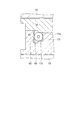
図1は、実施形態1に係るマイクロポンプを示す概観平面図、図2は概観正面図である。図1、図2において、マイクロポンプ10は、チューブユニット11を制御ユニット12の図示左側側面の開口部から空間110内にスライド挿入して装着し、蓋部材としての固定枠13により制御ユニット12に固定螺子90により固定されて一体に構成されている。
FIG. 1 is a schematic plan view showing the micropump according to the first embodiment, and FIG. 2 is a schematic front view. 1 and 2, the
チューブユニット11は、一部が円弧形状に配設される弾性を有するチューブ50と、チューブ50を保持する案内枠としての第1チューブ案内枠17と第2チューブ案内枠18と、チューブ50の流入口部52が連通し液体を収容するリザーバ14と、複数のフィンガー40〜46と、から構成されている。なお、以降、流体を薬液等の液体として表し説明する。
The
制御ユニット12は、カム20と、カム20に回転力を与える駆動部としてのモータと伝達機構と、モータの駆動制御を行う制御回路部(共に図示を省略する)と、を有して構成されている。
The
カム20、モータ、伝達機構、フィンガー40〜46、制御回路部は機枠としての第1機枠15と第2機枠16とによって形成される空間100の内部に保持されている。
The
また、チューブ50の一端は流出口部53であって、固定枠13を貫通して外部に突設され、リザーバ14から液体を外部に吐出する。
One end of the
リザーバ14の一部には、リザーバ14の内部に液体を注入、または封止するためのポートとしてのセプタム95が設けられている。セプタム95は、固定枠13の内部に突設されている。
A part of the
続いて、チューブユニット11、制御ユニット12、及び固定枠13の構成と、組立方法について説明する。
図3は、マイクロポンプの分解平面図、図4は分解正面図である。なお、図3,4において、(a)は固定枠13、(b)はチューブユニット11、(c)は制御ユニット12を示している。
Then, the structure of the
3 is an exploded plan view of the micropump, and FIG. 4 is an exploded front view. 3 and 4, (a) shows the fixed
図3、図4に示すように、制御ユニット12には、第1機枠15と第2機枠16とによって空間100,110が構成されている。空間100にはカム20と、モータ、伝達機構、制御回路部(図示を省略)が配設され、一方に開口部を有する空間110はチューブユニット11が装着される空間である。
As shown in FIGS. 3 and 4, in the
フィンガー40〜46は、案内枠としての第1チューブ案内枠17と第2チューブ案内枠18によって形成されるフィンガー案内孔85(フィンガー40〜46の一つ一つに対応して設けられる)に挿着されている。フィンガー40〜46は、一方の端部が空間110方向に突設され、他方の端部がチューブ50に当接する方向に突設され、チューブユニット11が制御ユニット12に装着されたときにチューブ50を圧閉可能な状態となる。
The
チューブユニット11は、チューブ50とリザーバ14とが連通部材により連結され、第1チューブ案内枠17と第2チューブ案内枠18とで保持された状態で、制御ユニット12の空間110に、図示左側から装着される。
The
なお、カム20は、回転中心Pを軸として回転する。チューブユニット11は、カム20の回転平面に対して平行に制御ユニット12に装着される。
The
また、チューブユニット11の固定枠13側近傍には、外周面に沿ってパッキン97が嵌着されており、チューブユニット11が制御ユニット12に挿着された状態で、空間110が密閉される。
Further, a packing 97 is fitted in the vicinity of the fixed
また、チューブユニット11は、凹形状の壁面18aが制御ユニット12の円弧状に突設された壁面15aに当接するまで制御ユニット12に押し込まれる。壁面15a,18aは互いにカム20の回転中心Pと同心円で形成されている。
Further, the
ここで、壁面15aと壁面18aが当接した状態で、チューブユニット11の制御ユニット側端部18c,18dは、制御ユニット12の内側側壁15b,15cとの間に隙間ができるよう寸法設定されている(図5も参照する)。
Here, in a state where the
この隙間は、壁面15aと壁面18aを確実に当接させ、チューブ50の円弧形状部分(フィンガー40〜46で押圧される範囲)の円弧中心P’をカム20の回転中心Pと一致させるために設けられている。
This gap ensures that the
チューブユニット11を制御ユニット12に挿着した後、固定枠13をチューブユニット11の尾部方向(空間110の開口部側)から装着する。具体的には、固定枠13に開設された貫通孔13d,13eに固定螺子90を挿入して、制御ユニット12の第1機枠15に設けられる螺子孔(図示せず)に螺着固定する。
After the
チューブ50の流出口部53と、リザーバ14に設けられるセプタム95とは、チューブユニット11から突設され、固定枠13を固定したときに、チューブ50をチューブ挿通孔13a、セプタム95をセプタム挿通孔13bに挿通して、流出口部53は固定枠13の外に突設、延在される。
An
第1チューブ案内枠17の固定枠13側側面には突起部96が形成されている。この突起部96は、チューブユニット11を制御ユニット12から抜き取る際に用いられる。突起部96は、固定枠13に穿設された凹部13c内に収容される。
A
続いて、上述したように組み立てられたマイクロポンプ10の各要素の構成、及び作用について図面を参照して説明する。
Next, the configuration and operation of each element of the
図5〜図7は、本実施形態に係るマイクロポンプを示し、図5は平面図、図6(a)は図5のA−P−A’切断面を示す断面図、(b)は(a)のF−F切断面を示す断面図、図7はチューブ保持構造を示す部分断面図である。まず、図5,6を参照して駆動部の構成について説明する。なお、図5は、第2機枠16及び第2チューブ案内枠18を透視して表している。
5 to 7 show the micropump according to the present embodiment, FIG. 5 is a plan view, FIG. 6A is a cross-sectional view taken along the line A-P-A 'in FIG. 5, and FIG. Sectional drawing which shows the FF cut surface of a), FIG. 7: is a fragmentary sectional view which shows a tube holding structure. First, the configuration of the drive unit will be described with reference to FIGS. FIG. 5 is a perspective view of the
駆動部は、モータとしてステップモータ70を備え、ステップモータ70の回転を伝達機構(モータ歯車71、第1伝達車72、第2伝達車73から構成される)を介してカム駆動歯車74まで伝達する。
The drive unit includes a
ステップモータ70は、モータ支持枠19により保持され、第1機枠15に固定螺子93によって固定されている。ステップモータ70はモータ歯車71を有する。
The
第1伝達車72、第2伝達車73は、第1機枠15と第2機枠16によって回転可能に軸支されている。
The
第1伝達車72は、伝達歯車72aがピニオン72bに軸止された状態で、第1機枠15に設けられる軸受115と、第2機枠16に設けられる軸受112によって軸支されている。
The
第2伝達車73は、伝達歯車73aがピニオン73bに軸止された状態で、第1機枠15に設けられる軸受113と、第2機枠16に設けられる軸受113によって軸支されている。
The
また、カム駆動歯車74は、カム軸75にカム20と共に軸止されてカム駆動車80を構成し、第1機枠15に設けられる軸受114と、第2機枠16に設けられる軸受114によって軸支されている。モータ歯車71からカム駆動歯車74までの間は、減速駆動となるように各歯車の歯数比が設定されると共に、カム20の所定の回転速度と回転トルクとを設定している。
The
ステップモータ70、第1伝達車72、第2伝達車73、カム駆動車80は、第1機枠15と第2機枠16とで構成される空間100に配設される。第1機枠15と第2機枠16の互いの接合面は密接される。
The
第1機枠15と第2機枠16の接合構造としては、図5に示すような固定螺子91を用いて固定する構造、互いの接合面を溶着または接着する構造等を採用できる。
As a joining structure of the
また、制御ユニット12には、制御回路部30が備えられており、図示しない回路基板に設けられる回路パターンを介してステップモータ70に接続され、ステップモータ70を所定の回転速度で回転する。
Further, the
カム20は、外周方向に凹凸を有し、最外周部にフィンガー押圧面21a〜21dが形成されている。フィンガー押圧面21a〜21dは、回転中心Pから等距離の同心円上に形成される。
The
また、フィンガー押圧面21aとフィンガー押圧面21b、フィンガー押圧面21bとフィンガー押圧面21c、フィンガー押圧面21cとフィンガー押圧面21d、及びフィンガー押圧面21dとフィンガー押圧面21a、の周方向ピッチと外形形状は等しく形成されている。
Moreover, the circumferential pitch and outer shape of the
フィンガー押圧面21a〜21dは、フィンガー押圧斜面22と回転中心Pを中心とする同心円上の円弧部23と連続して形成されている。この円弧部23は、フィンガー40〜46を押圧しない位置に設けられる。
The finger
また、フィンガー押圧面21a,21b,21c,21dの端部と円弧部23とは、回転中心Pから延長した直線部24で結ばれている。
Further, the end portions of the finger
次に、チューブユニット11の構成について図5、図6を参照して説明する。チューブ50はカム20に対向する一部が円弧形状を有しており、第1チューブ案内枠17に形成されるチューブ案内溝17cに装着されている。
Next, the structure of the
チューブ50の円弧形状の円弧中心P’(図3、参照)は、装着された状態でカム20の回転中心Pと一致している。チューブ50の一端はリザーバ14に連通し、他端は固定枠13のチューブ挿通孔13aを通って延在される流出口部53である。
The arc-shaped arc center P ′ (see FIG. 3) of the
フィンガー40〜46は、第1チューブ案内枠17と第2チューブ案内枠18によって形成されるフィンガー案内孔85に挿着されている。フィンガー案内孔85は、フィンガー40〜46の一つ一つに対応して設けられており、カム20の回転中心P(つまり、チューブ50の円弧中心P’と一致)から等間隔で放射状に延設されている。
The
なお、フィンガー40〜46は同じ形状で形成されているのでフィンガー43を例示して説明する。
Since the
フィンガー案内孔85は図6(b)に示すように、第1チューブ案内枠17形成された略U字形状の溝15hの図示上方の開口部を第2チューブ案内枠18で封止することにより構成される。フィンガー案内孔85は、チューブ案内溝17cから壁面18aまで貫通している。
As shown in FIG. 6B, the
フィンガー43は、図6(a)に示すように、円柱状の軸部43aと、軸部43aの一方の端部に設けられる鍔形状のチューブ押圧部43cと、他方の端部が半球状に丸められたカム当接部43bと、から構成されている。
As shown in FIG. 6A, the
チューブ押圧部43cの直径は、フィンガー案内孔85の直径よりも大きく設定され、フィンガー43の軸方向の移動を規制し、チューブユニット11から脱落することはない。
フィンガー43は、軸部43aを溝15hに開口部方向から装着した後、第2チューブ案内枠18を上方より第1チューブ案内枠17に装着することで、断面方向の位置が規制される。
The diameter of the
After the
チューブ50は、ほぼ全体をチューブ案内溝17c内に装着することで平面位置が規制されると共に、チューブ案内溝17cの側壁の一部にチューブ保持部としての突起部を形成して上方への浮き上がりを規制する。
The
図7は、チューブ保持構造を示す部分断面図である。なお、図7は、フィンガー40〜46の互いに隣り合うフィンガーの間の突起部のうちフィンガー45とフィンガー46の間の突起部を例示して説明する(図5も参照する)。
FIG. 7 is a partial cross-sectional view showing the tube holding structure. In addition, FIG. 7 illustrates and demonstrates the protrusion part between the
チューブ案内溝17cには、フィンガー45とフィンガー46との間にフィンガー45,46の進退を妨げない幅の突起部としてのチューブ案内側壁17fが設けられ、チューブ案内側壁17fの上部にチューブ50の上方一部にせり出すような突起部17eが形成されている。
The
このように、各フィンガーの間にチューブ案内側壁17fと突起部17eを設けることで、フィンガー40〜46が配設される範囲において、チューブの平面方向の位置規制と浮き上がりの抑制を行う。
Thus, by providing the tube
なお、本実施形態では、図5に示すようにチューブ50の流出口部53に近い位置、及び流入口部52に近い位置にも突起部17eと同様な機能を有する突起部17hが設けられている。
In the present embodiment, as shown in FIG. 5, a
チューブ50及びリザーバ14とフィンガー40〜46を第1チューブ案内枠17に装着した状態で、第1チューブ案内枠17と第2チューブ案内枠18とを、互いの接合面を密接させ、固定螺子92を用いて固定することで、チューブユニット11が構成される。
In a state where the
なお、チューブ50の流出口部53の近傍は、第1チューブ案内枠17と第2チューブ案内枠18とを固定した状態で、パッキンまたは接着等を用いてチューブ案内溝17cとチューブ50との間を密閉する。このようにすることで、チューブユニット11内が密閉構造となる。
The vicinity of the
また、チューブユニット11の固定枠13近傍の外周には、パッキン97が嵌着されており、チューブユニット11を制御ユニット12に挿着した状態で、内部を密閉空間とし、マイクロポンプ10を防水構造及び防塵構造としている。
なお、マイクロポンプ10が非防水構造でよい場合には、パッキン97は不要である。
Further, a packing 97 is fitted on the outer periphery of the
In addition, when the
また、チューブ案内溝17cのうち、少なくともフィンガー40〜46がチューブ50を押圧する平面範囲には、フィンガー40〜46が進行する方向にチューブ案内溝17cに沿った凹部により形成されたチューブ規制壁17dが形成されている。
In addition, in the
この凹部内には、弾性部材60が設けられている。つまり、弾性部材60は、チューブ規制壁17dとチューブ50との間に設けられる。弾性部材60は、チューブ50がフィンガー40〜46によって必要以上の押圧力で圧閉される際のダンパーとなりチューブ50が劣化しないように設けられている。なお、弾性部材60は、チューブ圧閉に耐える弾性力を有している。また、チューブ50との摩擦係数を小さくしておくことがより好ましい。
An
また、チューブ50の流入口部52とリザーバ14との接合部には互いの連通部材としてのエアベントフィルタ65が備えられている。エアベントフィルタ65の内部には、親液性を有し微細な孔が形成されるフィルタが備えられている。このフィルタは、液体は通過し、気泡の通過を遮断する。
In addition, an
なお、本実施形態では、エアベントフィルタをリザーバ14とチューブ50との連結部材とし、リザーバ14とチューブ50の分離、挿着を行うことができる。
In this embodiment, the air vent filter is a connecting member between the
フィルタに形成される孔は0.1〜1μmの範囲であって、液体を通過させ、リザーバ14内に発生する0.1μm以上または1μm以上の気泡のチューブ50への浸入を抑制する。
The pores formed in the filter are in the range of 0.1 to 1 μm and allow liquid to pass therethrough and suppress the intrusion of bubbles of 0.1 μm or more or 1 μm or more generated in the
なお、第1チューブ案内枠17の元部(固定枠13側)の側面及び裏面には突起部17b、先端部の側面及び裏面には突起部17nが形成され、第2チューブ案内枠18の元部及び先端部の外側表面にも同様な突起部18b,18eが形成されている。
In addition,
第1チューブ案内枠17と第2チューブ案内枠18を接合した状態で、突起部17b,18bが連続したリング状の突起部となり、突起部17n,18eとが連続したリング状の突起部となる。
In a state where the first
チューブユニット11は、制御ユニット12にスライド挿着される。この際、突起部17b,17n,18b,18eを設けることで、制御ユニット12とチューブユニット11の位置精度を高めると共に、挿着時または抜き取り時の抵抗を減じている。
The
なお、チューブユニット11の尾部(固定枠13側)には、溝96aを有する突起部96が形成されている。この突起部96は、制御ユニット12からチューブユニット11を溝96aを抓まんで抜き取るときに用いられる。
A
続いて、本実施形態による液体の輸送、吐出に係る作用について図5を参照して説明する。図5に示す状態では、カム20は、ステップモータ70からの回転力により伝達機構を介して回転され(図示、矢印R方向)、カム20のフィンガー押圧面21dでフィンガー44を押圧しチューブ50を圧閉している。
Next, the operation related to the transport and discharge of the liquid according to the present embodiment will be described with reference to FIG. In the state shown in FIG. 5, the
フィンガー45もフィンガー押圧面21dとフィンガー押圧斜面22との接合部に当接しており、チューブ50を圧閉している。また、フィンガー46はフィンガー押圧斜面22上でチューブ50を押圧しているが、フィンガー44の押圧量より小さく、チューブ50を完全には圧閉していない。
The
フィンガー41〜43は、カム20の円弧部23の範囲にあり、押圧しない初期位置にある。また、フィンガー40はカム20のフィンガー押圧斜面22に当接しているが、この位置では、まだチューブ50を圧閉していない。
The
この位置から、さらにカム20を矢印R方向に回転すると、カム20のフィンガー押圧面21dによって、フィンガー45,46の順で押圧してチューブ50を圧閉していく。フィンガー44はフィンガー押圧面21dから解除されチューブ50は開放される。チューブ50の液体流動部51には、フィンガーから圧閉が開放される位置、または、まだ圧閉されていない位置に液体が流入してくる。
When the
カム20をステップモータ70によりさらに回転すると、フィンガー押圧斜面22が、フィンガー40,41,42,43の順に液体の流入側から流出側に順次押圧していき、フィンガー押圧面21cに達したときにチューブ50を圧閉する。
When the
このような動作を繰り返すことにより、液体を流入口部52側から流出口部53側に向けて流動し、流出口部53から吐出する。
By repeating such an operation, the liquid flows from the
この際、カム20のフィンガー押圧面のいずれかには、フィンガー40〜46のうちの2本が当接し、次のフィンガーを押圧する位置に移動するときには、フィンガー40〜46のうちの1本を押圧する。このように、フィンガーを2本押圧する状態と、一本を押圧する状態と、を繰り返すことにより、少なくとも1本のフィンガーがチューブ50を常時圧閉している状態を形成する。このようなフィンガー40〜46の運動によるマイクロポンプの構造は蠕動駆動方式と呼ばれる。
At this time, any one of the finger pressing surfaces of the
従って、本実施形態によれば、チューブユニット11が、チューブ50を圧閉するフィンガー40〜46を押圧するカム20を含む制御ユニット12から分離可能であることから、チューブユニット11単体の状態ではチューブ50は開放された状態が維持される。そのため、チューブ50の継続的な圧閉による復元力の劣化に伴う吐出精度の低下を防止し、所望の吐出精度を維持することができる。
Therefore, according to the present embodiment, since the
また、チューブ50の圧閉と開放を長時間繰り返すことによりチューブ50の復元力が劣化することが考えられ、このような場合チューブ交換が必要となるが、一定時間使用後、チューブ50をチューブユニットとして容易に交換することができる。
In addition, it is considered that the restoring force of the
また、カム20とステップモータ70と伝達機構とを制御ユニット12として構成しているため、チューブユニット11を制御ユニット12を装着する際、前述した従来技術のようなピニオンとギヤとを噛合させて結合することが必要ないため、噛合させる過程における破壊はない。
Further, since the
また、チューブユニット11を制御ユニット12に対して水平方向に装着すれば、フィンガー40〜46をチューブ押圧可能な状態にすることができる。従って、従来技術のようにモータモジュールとポンプモジュールとの間に連結機構を必要とせず、構造を簡素化でき、組立性を向上させることができ、さらに、薄型化を実現できる。
Moreover, if the
また、チューブユニット11は、カム20とステップモータ70と伝達機構と制御回路部30を含む制御ユニット12に対してはるかに低コストとすることができる。そこで、薬液等に直接接触するチューブ50を含むチューブユニット11を使い捨て使用とし、制御ユニット12を繰り返し使用すれば、ランニングコストを低減することができる。
Moreover, the
また、チューブ50の内径及び外径は寸法ばらつきが考えられる。これらの寸法ばらつきは吐出精度に影響する。そこで、チューブ50と、チューブ50の寸法に適合する長さのフィンガー40〜46を1セットとしてチューブユニット化することで、吐出精度を向上させることができる。
In addition, the inner diameter and the outer diameter of the
また、チューブユニット11を、制御ユニット12に設けられる空間110の内部に装着することから、制御ユニット12を構成する第1機枠15と第2機枠16とがケースの機能を有し、チューブユニット11と制御ユニット12とを収容するためのケースが不要となり、構造を簡素化できる。
Further, since the
また、チューブユニット11を制御ユニット12に対して水平方向に挿着する構造のため、従来技術のような積み重ね構造よりも薄型化することができる。
Further, since the
また、本実施形態のマイクロポンプ10は、カム20の回転によりフィンガー40〜46を押圧してチューブ50を圧閉する構成である。従って、チューブ50の円弧形状の円弧中心P’とカムの回転中心Pとを一致させることが必要である。
Further, the
そこで、チューブユニット11を制御ユニット12に装着する際、双方に案内部(壁面18aと壁面15a)を設け互いに当接することにより、チューブ50の円弧形状の円弧中心P’とカムの回転中心Pとを略一致させることができ、専用の位置規制部材を設けなくても、フィンガー40〜46の全てがチューブ圧閉を確実に行うことができる。
Therefore, when the
なお、本実施形態では、第1機枠15、第2機枠16、第1チューブ案内枠17、第2チューブ案内枠18のうちの一つまたは全部、あるいは、第1機枠15、第2機枠16、第1チューブ案内枠17、第2チューブ案内枠18の一部または全体が透明材料で形成されている。
In the present embodiment, one or all of the
このようにすることにより、内部の構成部品または各構成部品の係合関係や駆動状態を視認することができ、正常な状態であるか、どこに不具合があるか等を検出することができる。なお、透明にする範囲は、少なくとも視認したい部分の範囲とすればよい。 By doing in this way, it is possible to visually recognize the internal component parts or the engagement relationship and drive state of each component part, and it is possible to detect whether it is in a normal state or where there is a defect. In addition, what is necessary is just to let the range made transparent at least the range of the part to view visually.
また、リザーバ14の上部方向または下部方向から視認できるようにすれば、収容する液体量を観察することができる。リザーバ14を透明容器とすればなおよい。
Further, if the
また、リザーバ14をチューブユニット11に収容することで、リザーバ14内の液体が無くなった時点でチューブ50を含むチューブユニット11を交換すれば、チューブ50の劣化前に交換することができることから、マイクロポンプの信頼性を高めることができる。
In addition, by storing the
また、リザーバ14とチューブ50との間には、エアベントフィルタ65を連結部材として備え、互いに着脱可能な構成としている。従って、薬液が少なくなったリザーバ14を取り外し、薬液が収容されたリザーバ14をチューブ50に接続し、長時間にわたってマイクロポンプを使用することができる。
Further, an
また、リザーバ14とチューブ50との間にエアベントフィルタ65を設けることにより、液体中に含まれる気泡のチューブ50内への通過を遮断し、液体が薬液であって生体内に吐出する場合に、生体内に気泡が注入されることを防止することができ、安全性を高める。
Further, by providing an
また、リザーバ14が、内部に液体を流入、且つ封止するためのポートとしてのセプタム95を備えている。リザーバ14にセプタム95を設けることにより、チューブ50をリザーバ14に接続した状態で、リザーバ14に液体の注入を容易に行うことができる。
In addition, the
さらに、セプタム95を、第1チューブ案内枠17の外部に突設し、固定枠13の外側からセプタム95の流入口部が覗くように配設することにより、チューブユニット11の状態、または制御ユニット12に装着した状態で、リザーバ14に液体の注入を容易に行うことができる。
Further, the
さらに、マイクロポンプ10を使用している状態においても液体の追加注入を容易に行うことができる。
(実施形態2)
Further, even when the
(Embodiment 2)
続いて、実施形態2について図面を参照して説明する。実施形態2は、チューブユニット11を制御ユニット12に付勢する弾性部材を設けていることに特徴を有する。従って、実施形態1との相違個所を中心に説明する。
Next, Embodiment 2 will be described with reference to the drawings. The second embodiment is characterized in that an elastic member that biases the
図8は、実施形態2に係るマイクロポンプの一部を示し、(a)は部分平面図、(b)は(a)のE−E切断面を示す断面図である。図8(a)において、チューブユニット11と固定枠13の間には、弾性部材としての板バネ99が備えられている。
8A and 8B show a part of the micropump according to the second embodiment, where FIG. 8A is a partial plan view, and FIG. 8B is a cross-sectional view showing the EE cut surface of FIG. In FIG. 8A, a
板バネ99は、固定枠13のチューブユニット11側に設けられた凹形状の板バネ固定部13fに固定される。板バネ99の力点は中心線J上にあって、チューブユニット11をカム20の回転中心Pに向かって付勢している。
The
そのことによって、チューブユニット11の壁面18aと制御ユニット12の壁面15aとが、中心線J上で当接される。
As a result, the
板バネ99の固定は、図8(b)に示すように、固定枠13の板バネ固定部13fに突設された案内軸13gを熱溶着等の固定手段を用いて行われる。なお、板バネ99は、固定枠13を固定した状態で脱落しなければよいので必ずしも固定しなくてもよい。
As shown in FIG. 8B, the
チューブユニット11を制御ユニット12に固定枠13により固定する場合、チューブユニット11、制御ユニット12、固定枠13等の構成部品の寸法ばらつきにより、チューブユニット11と制御ユニット12との間に水平方向(平面方向)の隙間が発生し、チューブ50をフィンガー40〜46により圧閉できなくなることが考えられる。
When the
そこで、板バネ99によりチューブユニット11を制御ユニット12の方向に付勢することにより、互いの壁面15a,18aを当接させて、チューブ50の円弧形状の円弧中心P’とカム20の回転中心Pとを一致させ、フィンガー40〜46の全てがチューブ50を確実に圧閉させることができる。
Therefore, by urging the
また、板バネ99の付勢力は、フィンガー40〜46のチューブ押圧力よりも大きくなるよう設定される。
Further, the urging force of the
このようにすれば、フィンガー40〜46がチューブ50を圧閉する際に、チューブユニット11(つまり、チューブ50)がフィンガー40〜46から遠ざかる方向に移動しないので、確実にチューブを圧閉することができる。
In this way, when the
なお、本実施形態では、弾性部材として板バネ99を例示したが、板バネに限らず、コイルバネ、厚さ方向に弾性を有する平板でもよく、また、これらを複数用いる構造としてもよい。
(実施形態3)
In the present embodiment, the
(Embodiment 3)
続いて、実施形態3に係るマイクロポンプについて図面を参照して説明する。実施形態3は、電源がチューブユニットに収容されていることを特徴としている。従って、実施形態1との相違個所を中心に説明する。 Next, a micro pump according to Embodiment 3 will be described with reference to the drawings. Embodiment 3 is characterized in that the power source is accommodated in the tube unit. Therefore, the description will focus on the differences from the first embodiment.
図9は実施形態3に係るマイクロポンプの一部を示し、(a)は部分平面図、(b)は(a)のG−G切断面を示す断面図である。図9(a),(b)において、電源としての小型ボタン型電池120(以降、単に電池120と表す)は、チューブユニット11の内部に収容されている。
9A and 9B show a part of the micropump according to the third embodiment, where FIG. 9A is a partial plan view, and FIG. 9B is a cross-sectional view showing a GG cut surface of FIG. 9A and 9B, a small button type battery 120 (hereinafter simply referred to as a battery 120) as a power source is accommodated in the
電池120はリザーバ14と共に、第1チューブ案内枠17に形成される凹部内に装着されて、上部を第2チューブ案内枠18によって封鎖される。ここで、電池120の図示下方面をマイナス極、上面及び側面をプラス極とするとき、下方面はマイナス端子121に接続され、側面がプラス端子122に接続される。
The
マイナス端子121及びプラス端子122は、図示しないリードによって第1チューブ案内枠17の端部に植立される接続端子123,124に接続されている。
The
接続端子123,124は、第1チューブ案内枠17から突設されて、制御ユニット12の内部にまで延在されている。制御ユニット12には、接続端子123,124に電気的に独立して接続する接続端子(図示せず)が設けられ、これら接続端子は制御回路部30(図5、参照)に接続される。
The
チューブユニット11を制御ユニット12に装着した状態で、電池120から制御回路部30に電力が供給され、マイクロポンプ10が駆動可能な状態となる。
With the
なお、電池120をチューブユニット11の内部に収容し、リザーバ14をチューブユニットの外部に備える構造としてもよい。
The
使用する薬液を変更する場合、または使用したチューブ50を交換する場合に、チューブユニット11としてチューブ50と共に電池120を交換することで、使用途中で電池容量が不足することを防止することができる。
When the chemical solution to be used is changed or when the used
また、電池120は、チューブユニット11に対して着脱可能である。図9に示す構成では、第1チューブ案内枠17と第2チューブ案内枠18とを接合する固定螺子92(図5、参照)を外して、電池120を着脱する例を示している。
Further, the
ここで、電池120の着脱構造としては、第2チューブ案内枠18に電池蓋を設ける構造としてもよく、また、電池120をチューブユニット11の尾部(固定枠13側)からスライド挿入する構造として、固定枠13を外して電池120の着脱をする構造としてもよい。
Here, as a structure for attaching and detaching the
なお、本実施形態では、電池として小型ボタン型電池を例示したが、他にシート電池、リチウムイオン電池等の二次電池を採用することができる。これらの電池を用いる場合はリザーバと重ねて配設することができ、電池をチューブユニット内に収容する構成としても、リザーバの容量を大きくできるという利点がある。
(実施形態4)
In the present embodiment, a small button type battery is exemplified as the battery, but other secondary batteries such as a sheet battery and a lithium ion battery can be adopted. When these batteries are used, they can be disposed so as to overlap with the reservoir, and even when the battery is accommodated in the tube unit, there is an advantage that the capacity of the reservoir can be increased.
(Embodiment 4)
続いて、実施形態4に係るマイクロポンプについて図面を参照して説明する。実施形態4は、チューブユニットが制御ユニットに対して正確な位置に挿着されているかを検出する接続端子と検出端子とからなる検出器を備えていることに特徴を有する。従って、実施形態1との相違個所を中心に説明する。 Next, a micro pump according to Embodiment 4 will be described with reference to the drawings. The fourth embodiment is characterized in that a detector including a connection terminal and a detection terminal for detecting whether the tube unit is inserted in an accurate position with respect to the control unit is provided. Therefore, the description will focus on the differences from the first embodiment.
図10は、実施形態4に係るマイクロポンプの一部を示し、(a)は部分平面図、(b)は(a)のH−H切断面を示す断面図である。図10(a),(b)において、チューブユニット11に形成される壁面18aの両側の半島状端部に、第1接続端子66と第2接続端子67とが植立されている。
10A and 10B show a part of the micropump according to the fourth embodiment, where FIG. 10A is a partial plan view, and FIG. 10B is a cross-sectional view showing the HH cut surface of FIG. 10A and 10B, the
第1接続端子66と第2接続端子67とは、一方の端部が接続リード94によって電気的に接続されている。また、他方の端部は制御ユニット12の内部まで入り込むように制御ユニット側端部18c,18dから突設されている。
One end of the
制御ユニット12(第1機枠15)には、略U字バネ形状の第1検出端子68、第2検出端子69とが備えられている。第1検出端子68、第2検出端子69とは同じ形状のため、第2検出端子を例示して説明する。
The control unit 12 (first machine casing 15) includes a first detection terminal 68 and a
第2検出端子69は、第1機枠15に設けられる凹部内に撓められて装着される。ここで第2検出端子69の腕部69a,69bは、凹部内の対向する側壁を押圧する。
The
従って、腕部69aは、凹部内の側壁15gによって位置規制される。側壁15gの位置は、カム20の回転中心P位置に対して正確に位置規制されている。また、第1接続端子66と第2接続端子67の先端部位置も、カム20の回転中心P位置に対して正確に位置規制されている。
Therefore, the position of the
チューブユニット11の円弧状の壁面18aと制御ユニットの円弧状の壁面15aとが当接する位置までチューブユニット11を制御ユニット12に装着したとき、第2接続端子67が第2検出端子69に電気的に接続される。同時に第1接続端子66も第1検出端子68に電気的に接続される。
When the
第2検出端子69にはリード64が接続され、リード64は制御回路部30の検出端子A(図示せず)に接続されている。一方、第1検出端子68にはリード63が接続され、リード63は制御回路部30の検出端子B(図示せず)に接続されている。
A lead 64 is connected to the
ここで、第2接続端子67と第2検出端子69、及び第1接続端子66と第1検出端子68の両方が、電気的に接続されたことを検出端子Aと検出端子Bで検出したとき、チューブユニット11の壁面18aと制御ユニットの壁面15aとが当接したと判定する。
Here, when the detection terminal A and the detection terminal B detect that both the
このような状態のとき、チューブ50の円弧形状の円弧中心P’とカム20の回転中心Pとが一致していると判定し、制御回路部30によりステップモータ70(図示せず)を駆動可能な状態にする。
In such a state, it is determined that the arc center P ′ of the arc shape of the
また、第2接続端子67と第2検出端子69、及び第1接続端子66と第1検出端子68の両方が、電気的に接続されていない場合には、チューブユニット11と制御ユニット12とが、所定の位置に装着されていない状態と判定し、チューブユニット11の制御ユニット12への装着をやり直す。
When both the
なお、本実施形態では検出器として接点方式を例示したが、光検出や磁気検出構造を採用することができる。 In this embodiment, the contact method is exemplified as the detector, but a light detection or magnetic detection structure can be adopted.
このような構成にすれば、チューブ50の円弧形状の円弧中心P’とカム20の回転中心Pとを一致したことを検出した場合にステップモータ70を駆動することにより、設定通りのチューブ50の圧閉と開放ができるため、液体を所望の単位時間当り流動量で輸送することができる。
(実施形態5)
With such a configuration, when it is detected that the arc center P ′ of the arc shape of the
(Embodiment 5)
続いて、実施形態5に係るマイクロポンプについて図面を参照して説明する。実施形態5は、電源としての電池が制御ユニットに収容されていることを特徴としている。従って、実施形態1との相違個所を中心に説明する。 Next, a micro pump according to Embodiment 5 will be described with reference to the drawings. Embodiment 5 is characterized in that a battery as a power source is accommodated in a control unit. Therefore, the description will focus on the differences from the first embodiment.
図11は、実施形態5に係るマイクロポンプの一部を示し、(a)は平面図、(b)は(a)のI−I切断面を示す断面図である。図11において、電源としての小型ボタン型電池120(以降、単に電池120と表す)は制御ユニット12に収容されている。
11A and 11B show a part of the micropump according to the fifth embodiment. FIG. 11A is a plan view, and FIG. 11B is a cross-sectional view taken along the line II of FIG. In FIG. 11, a small button type battery 120 (hereinafter simply referred to as a battery 120) as a power source is accommodated in the
電池120は、第1機枠15に形成される凹部内に装着されて、上部を電池蓋130によって封鎖、固定される。ここで、電池120の図示下方面をマイナス極、上面及び側面をプラス極とするとき、下方面はマイナス端子121に接続され、側面がプラス端子122に接続される。
The
マイナス端子121及びプラス端子122は、図示しないリードによって制御回路部30の電源端子(図示せず)に接続される。
The
電池蓋130は、電池120の外周を取り巻くように突設される電池案内部131と、鍔部134を有している。電池案内部131の外周部には螺子132が形成されており、第2機枠16の螺子部に螺合することにより、電池120を固定する。
The
電池蓋130には溝133が形成され、この溝にコイン等を差し込んで回転することで、電池蓋130の開閉を行う。
A
電池蓋130を螺合する際、鍔部134と第2機枠16との接合部は密接される。鍔部134と第2機枠16の間にシール材としてのパッキンを用いれば一層密閉性を向上させることができる。
When the
なお、電池蓋130の固定構造としては、第2機枠16に圧入する構造としてもよい。また、電池蓋130をバヨネット構造としてもよい。また、第1機枠15と第2機枠16の側面に開口部を設け、この開口部から電池120を挿入して、固定枠13と同様な固定枠固定構造にて固定する構造としてもよい。
The structure for fixing the
このように電池120を制御ユニット12に収容することにより、チューブユニット11を制御ユニット12に装着した状態、または、制御ユニット12単体の状態で電池交換を行うことができる。
By storing the
電池120を制御ユニット12に収容することにより、制御回路部30と電池との接続を、実施形態3(図9、参照)のような接続端子123,124を用いることなく行うことができ、構造を簡素化できる。
By accommodating the
また、制御ユニット12のチューブユニット11が装着される範囲以外の空間に電池120を配設することで、チューブユニット11内に電池120を装着する構成に比べ電池120を厚くできるので、容量の大きい電池を採用することができる。
Further, by disposing the
さらに、チューブユニット11の空きスペースが増えるので、その分、リザーバ14の液体容量を増やすことができる。
Furthermore, since the empty space of the
以上、前述した実施形態1〜実施形態5によるマイクロポンプ10は、小型化、薄型化が可能で、微量流量を安定して連続的に流動することができるため、生体内または生体表面に装着し、新薬の開発やドラッグデリバリなどの医療用に好適である。また、様々な機械装置において、装置内、または装置外に搭載し、水や食塩水、薬液、油類、芳香液、インク、気体等の流体の輸送に利用することができる。さらに、マイクロポンプ単独で、流体の流動、供給に利用することができる。
As described above, the
10…マイクロポンプ、11…チューブユニット、12…制御ユニット、13…固定枠、14…リザーバ、15…第1機枠、16…第2機枠、17…第1チューブ案内枠、18…第2チューブ案内枠、20…カム、30…制御回路部、40〜46…フィンガー、50…チューブ、70…ステップモータ、120…電池。
DESCRIPTION OF
Claims (7)
前記チューブの円弧形状の円弧中心方向から放射状に配設される複数のフィンガーと、
前記チューブが挿着されるチューブ案内溝が形成された案内枠と、
前記複数のフィンガーの間に設けられ、前記複数のフィンガーが配設される方向における前記チューブの位置規制を行うチューブ案内壁と、
前記複数のフィンガーを前記チューブの流入側から流出側に順次押圧するカムと、
前記カムに回転力を与える駆動部と、
前記駆動部の駆動制御を行う制御回路部と、
前記チューブの流入口部が連通するリザーバと、
前記制御回路部に電力を供給する電源と、を備え、
前記チューブと前記複数のフィンガーと前記案内枠とを少なくとも有するチューブユニットと、前記カムと前記駆動部と前記制御回路部とを少なくとも有する制御ユニットとが着脱可能に構成され、
前記電源が、前記チューブユニットに収容されていることを特徴とするポンプ。 A tube partially elastic in an arc shape, and
A plurality of fingers arranged radially from the arc center direction of the arc shape of the tube;
A guide frame in which a tube guide groove into which the tube is inserted is formed;
A tube guide wall that is provided between the plurality of fingers and regulates the position of the tube in a direction in which the plurality of fingers are disposed;
A cam that sequentially presses the plurality of fingers from the inflow side to the outflow side of the tube;
A drive unit for applying a rotational force to the cam;
A control circuit unit for controlling the driving of the driving unit;
A reservoir in communication with the inlet portion of the tube;
A power supply for supplying power to the control circuit unit,
A tube unit having at least the tube, the plurality of fingers, and the guide frame, and a control unit having at least the cam, the drive unit, and the control circuit unit are configured to be detachable .
The pump, wherein the power source is accommodated in the tube unit.
前記チューブ案内壁は前記複数のフィンガーのそれぞれの間に設けられていることを特徴とするポンプ。 The pump according to claim 1 , wherein
The pump characterized in that the tube guide wall is provided between each of the plurality of fingers.
前記案内枠が前記チューブ案内溝によって前記チューブを保持するとともに、前記複数のフィンガーを保持することを特徴とするポンプ。 The pump according to claim 1 , wherein
The pump, wherein the guide frame holds the tube by the tube guide groove and holds the plurality of fingers.
前記チューブ案内壁は前記複数のフィンガーを保持する前記案内枠に形成された突起部であることを特徴とするポンプ。 The pump according to any one of claims 1 to 3 ,
The pump characterized in that the tube guide wall is a protrusion formed on the guide frame for holding the plurality of fingers.
前記リザーバが、前記チューブユニットに収容されていることを特徴とするポンプ。 The pump according to any one of claims 1 to 4 ,
The pump, wherein the reservoir is accommodated in the tube unit.
一部が円弧形状に配設され弾性を有するチューブと、
前記チューブの円弧形状の円弧中心方向から放射状に配設された複数のフィンガーと、
前記チューブが挿着されるチューブ案内溝が形成された案内枠と、
前記複数のフィンガーの間に設けられ、前記複数のフィンガーが配設される方向における前記チューブの位置規制を行うチューブ案内壁と、を有し、
前記制御回路部に電力を供給する電源が収容されていることを特徴とするチューブユニット。 It is configured to be detachable from a control unit having a cam, a drive unit that applies a rotational force to the cam, and a control circuit unit that performs drive control of the drive unit,
A tube partially elastic in an arc shape, and
A plurality of fingers arranged radially from the arc center direction of the arc shape of the tube;
A guide frame in which a tube guide groove into which the tube is inserted is formed;
A tube guide wall that is provided between the plurality of fingers and regulates the position of the tube in a direction in which the plurality of fingers are disposed;
A tube unit comprising a power supply for supplying power to the control circuit unit.
前記チューブの流入口部に連通するリザーバが収容されていることを特徴とするチューブユニット。 The tube unit according to claim 6 ,
A tube unit containing a reservoir communicating with an inlet portion of the tube.
Priority Applications (1)
| Application Number | Priority Date | Filing Date | Title |
|---|---|---|---|
| JP2014076780A JP5915688B2 (en) | 2014-04-03 | 2014-04-03 | Pump, tube unit |
Applications Claiming Priority (1)
| Application Number | Priority Date | Filing Date | Title |
|---|---|---|---|
| JP2014076780A JP5915688B2 (en) | 2014-04-03 | 2014-04-03 | Pump, tube unit |
Related Parent Applications (1)
| Application Number | Title | Priority Date | Filing Date |
|---|---|---|---|
| JP2013112662A Division JP5601400B2 (en) | 2013-05-29 | 2013-05-29 | Pump and tube unit |
Publications (2)
| Publication Number | Publication Date |
|---|---|
| JP2014122641A JP2014122641A (en) | 2014-07-03 |
| JP5915688B2 true JP5915688B2 (en) | 2016-05-11 |
Family
ID=51403293
Family Applications (1)
| Application Number | Title | Priority Date | Filing Date |
|---|---|---|---|
| JP2014076780A Expired - Fee Related JP5915688B2 (en) | 2014-04-03 | 2014-04-03 | Pump, tube unit |
Country Status (1)
| Country | Link |
|---|---|
| JP (1) | JP5915688B2 (en) |
Family Cites Families (3)
| Publication number | Priority date | Publication date | Assignee | Title |
|---|---|---|---|---|
| JP2005351131A (en) * | 2004-06-09 | 2005-12-22 | Seiko Epson Corp | Fluid transport device |
| JP3702901B1 (en) * | 2005-01-26 | 2005-10-05 | セイコーエプソン株式会社 | Fluid transport device and fluid transporter |
| JP4952492B2 (en) * | 2006-12-07 | 2012-06-13 | セイコーエプソン株式会社 | Micro pump, control unit |
-
2014
- 2014-04-03 JP JP2014076780A patent/JP5915688B2/en not_active Expired - Fee Related
Also Published As
| Publication number | Publication date |
|---|---|
| JP2014122641A (en) | 2014-07-03 |
Similar Documents
| Publication | Publication Date | Title |
|---|---|---|
| JP5282508B2 (en) | Control unit, tube unit, micro pump | |
| JP5298699B2 (en) | Control unit, tube unit, micro pump | |
| JP5195368B2 (en) | Tube unit, control unit, micro pump | |
| CN107847672B (en) | Dosing solution device and dosing solution unit | |
| KR102619178B1 (en) | Apparatus for Infusing medical liquid | |
| US9138524B2 (en) | Sensing system for detecting a substance in a dialysate | |
| CN103945877B (en) | Sensing system for detecting a substance in a dialysate | |
| JP2018512183A5 (en) | ||
| JP2015167709A (en) | liquid transport device and pump unit | |
| JP2009216080A (en) | Tube unit, control unit, and micropump | |
| CN104721903A (en) | Liquid Transport Apparatus | |
| JP5915688B2 (en) | Pump, tube unit | |
| JP5601400B2 (en) | Pump and tube unit | |
| US7950908B2 (en) | Fluid transporting device of a peristalic type with tube and push pin arrangement | |
| JP5915687B2 (en) | Pump, tube unit | |
| JP5601403B2 (en) | Pump and control unit | |
| JP3702901B1 (en) | Fluid transport device and fluid transporter | |
| JP5098677B2 (en) | Micro pump, pump module, drive module | |
| JP2010133318A (en) | Tube unit, control unit, and micropump | |
| JP2021165734A (en) | Exhalation collecting device and exhalation collecting apparatus | |
| KR20250154231A (en) | Drug injection apparatus | |
| JP5987317B2 (en) | Liquid transport device | |
| HK1145650A (en) | Medicine administration device |
Legal Events
| Date | Code | Title | Description |
|---|---|---|---|
| A521 | Written amendment |
Free format text: JAPANESE INTERMEDIATE CODE: A523 Effective date: 20140428 |
|
| A621 | Written request for application examination |
Free format text: JAPANESE INTERMEDIATE CODE: A621 Effective date: 20140428 |
|
| RD04 | Notification of resignation of power of attorney |
Free format text: JAPANESE INTERMEDIATE CODE: A7424 Effective date: 20150109 |
|
| A977 | Report on retrieval |
Free format text: JAPANESE INTERMEDIATE CODE: A971007 Effective date: 20150218 |
|
| A131 | Notification of reasons for refusal |
Free format text: JAPANESE INTERMEDIATE CODE: A131 Effective date: 20150303 |
|
| A521 | Written amendment |
Free format text: JAPANESE INTERMEDIATE CODE: A523 Effective date: 20150415 |
|
| A02 | Decision of refusal |
Free format text: JAPANESE INTERMEDIATE CODE: A02 Effective date: 20151006 |
|
| A521 | Written amendment |
Free format text: JAPANESE INTERMEDIATE CODE: A523 Effective date: 20151228 |
|
| A911 | Transfer of reconsideration by examiner before appeal (zenchi) |
Free format text: JAPANESE INTERMEDIATE CODE: A911 Effective date: 20160112 |
|
| TRDD | Decision of grant or rejection written | ||
| A01 | Written decision to grant a patent or to grant a registration (utility model) |
Free format text: JAPANESE INTERMEDIATE CODE: A01 Effective date: 20160308 |
|
| A61 | First payment of annual fees (during grant procedure) |
Free format text: JAPANESE INTERMEDIATE CODE: A61 Effective date: 20160321 |
|
| R150 | Certificate of patent or registration of utility model |
Ref document number: 5915688 Country of ref document: JP Free format text: JAPANESE INTERMEDIATE CODE: R150 |
|
| LAPS | Cancellation because of no payment of annual fees |