JP5911547B1 - Control device for internal combustion engine - Google Patents
Control device for internal combustion engine Download PDFInfo
- Publication number
- JP5911547B1 JP5911547B1 JP2014213378A JP2014213378A JP5911547B1 JP 5911547 B1 JP5911547 B1 JP 5911547B1 JP 2014213378 A JP2014213378 A JP 2014213378A JP 2014213378 A JP2014213378 A JP 2014213378A JP 5911547 B1 JP5911547 B1 JP 5911547B1
- Authority
- JP
- Japan
- Prior art keywords
- ignition
- energization
- timing
- internal combustion
- combustion engine
- Prior art date
- Legal status (The legal status is an assumption and is not a legal conclusion. Google has not performed a legal analysis and makes no representation as to the accuracy of the status listed.)
- Expired - Fee Related
Links
- 238000002485 combustion reaction Methods 0.000 title claims abstract description 74
- 230000009849 deactivation Effects 0.000 claims abstract description 41
- 230000000415 inactivating effect Effects 0.000 claims description 2
- 238000007599 discharging Methods 0.000 claims 1
- 239000000446 fuel Substances 0.000 description 19
- 239000000203 mixture Substances 0.000 description 9
- 238000000034 method Methods 0.000 description 8
- 230000015556 catabolic process Effects 0.000 description 6
- 230000006835 compression Effects 0.000 description 5
- 238000007906 compression Methods 0.000 description 5
- 238000010586 diagram Methods 0.000 description 3
- 238000001514 detection method Methods 0.000 description 2
- 230000006866 deterioration Effects 0.000 description 2
- 238000002347 injection Methods 0.000 description 2
- 239000007924 injection Substances 0.000 description 2
- 238000012545 processing Methods 0.000 description 2
- 239000003990 capacitor Substances 0.000 description 1
- 239000003054 catalyst Substances 0.000 description 1
- 238000007796 conventional method Methods 0.000 description 1
- 230000007423 decrease Effects 0.000 description 1
- 230000003111 delayed effect Effects 0.000 description 1
- 239000000428 dust Substances 0.000 description 1
- 238000002474 experimental method Methods 0.000 description 1
- 238000012423 maintenance Methods 0.000 description 1
- 230000010349 pulsation Effects 0.000 description 1
- 230000000284 resting effect Effects 0.000 description 1
- 230000002459 sustained effect Effects 0.000 description 1
Images


Classifications
-
- F—MECHANICAL ENGINEERING; LIGHTING; HEATING; WEAPONS; BLASTING
- F02—COMBUSTION ENGINES; HOT-GAS OR COMBUSTION-PRODUCT ENGINE PLANTS
- F02D—CONTROLLING COMBUSTION ENGINES
- F02D13/00—Controlling the engine output power by varying inlet or exhaust valve operating characteristics, e.g. timing
- F02D13/02—Controlling the engine output power by varying inlet or exhaust valve operating characteristics, e.g. timing during engine operation
- F02D13/06—Cutting-out cylinders
-
- F—MECHANICAL ENGINEERING; LIGHTING; HEATING; WEAPONS; BLASTING
- F01—MACHINES OR ENGINES IN GENERAL; ENGINE PLANTS IN GENERAL; STEAM ENGINES
- F01L—CYCLICALLY OPERATING VALVES FOR MACHINES OR ENGINES
- F01L13/00—Modifications of valve-gear to facilitate reversing, braking, starting, changing compression ratio, or other specific operations
- F01L13/0005—Deactivating valves
-
- F—MECHANICAL ENGINEERING; LIGHTING; HEATING; WEAPONS; BLASTING
- F02—COMBUSTION ENGINES; HOT-GAS OR COMBUSTION-PRODUCT ENGINE PLANTS
- F02D—CONTROLLING COMBUSTION ENGINES
- F02D37/00—Non-electrical conjoint control of two or more functions of engines, not otherwise provided for
- F02D37/02—Non-electrical conjoint control of two or more functions of engines, not otherwise provided for one of the functions being ignition
-
- F—MECHANICAL ENGINEERING; LIGHTING; HEATING; WEAPONS; BLASTING
- F02—COMBUSTION ENGINES; HOT-GAS OR COMBUSTION-PRODUCT ENGINE PLANTS
- F02D—CONTROLLING COMBUSTION ENGINES
- F02D41/00—Electrical control of supply of combustible mixture or its constituents
- F02D41/008—Controlling each cylinder individually
- F02D41/0087—Selective cylinder activation, i.e. partial cylinder operation
-
- F—MECHANICAL ENGINEERING; LIGHTING; HEATING; WEAPONS; BLASTING
- F02—COMBUSTION ENGINES; HOT-GAS OR COMBUSTION-PRODUCT ENGINE PLANTS
- F02P—IGNITION, OTHER THAN COMPRESSION IGNITION, FOR INTERNAL-COMBUSTION ENGINES; TESTING OF IGNITION TIMING IN COMPRESSION-IGNITION ENGINES
- F02P5/00—Advancing or retarding ignition; Control therefor
- F02P5/04—Advancing or retarding ignition; Control therefor automatically, as a function of the working conditions of the engine or vehicle or of the atmospheric conditions
- F02P5/045—Advancing or retarding ignition; Control therefor automatically, as a function of the working conditions of the engine or vehicle or of the atmospheric conditions combined with electronic control of other engine functions, e.g. fuel injection
-
- F—MECHANICAL ENGINEERING; LIGHTING; HEATING; WEAPONS; BLASTING
- F02—COMBUSTION ENGINES; HOT-GAS OR COMBUSTION-PRODUCT ENGINE PLANTS
- F02P—IGNITION, OTHER THAN COMPRESSION IGNITION, FOR INTERNAL-COMBUSTION ENGINES; TESTING OF IGNITION TIMING IN COMPRESSION-IGNITION ENGINES
- F02P5/00—Advancing or retarding ignition; Control therefor
- F02P5/04—Advancing or retarding ignition; Control therefor automatically, as a function of the working conditions of the engine or vehicle or of the atmospheric conditions
- F02P5/145—Advancing or retarding ignition; Control therefor automatically, as a function of the working conditions of the engine or vehicle or of the atmospheric conditions using electrical means
- F02P5/15—Digital data processing
- F02P5/1502—Digital data processing using one central computing unit
-
- F—MECHANICAL ENGINEERING; LIGHTING; HEATING; WEAPONS; BLASTING
- F01—MACHINES OR ENGINES IN GENERAL; ENGINE PLANTS IN GENERAL; STEAM ENGINES
- F01L—CYCLICALLY OPERATING VALVES FOR MACHINES OR ENGINES
- F01L1/00—Valve-gear or valve arrangements, e.g. lift-valve gear
- F01L1/02—Valve drive
- F01L1/04—Valve drive by means of cams, camshafts, cam discs, eccentrics or the like
- F01L1/047—Camshafts
- F01L1/053—Camshafts overhead type
- F01L2001/0537—Double overhead camshafts [DOHC]
-
- F—MECHANICAL ENGINEERING; LIGHTING; HEATING; WEAPONS; BLASTING
- F01—MACHINES OR ENGINES IN GENERAL; ENGINE PLANTS IN GENERAL; STEAM ENGINES
- F01L—CYCLICALLY OPERATING VALVES FOR MACHINES OR ENGINES
- F01L13/00—Modifications of valve-gear to facilitate reversing, braking, starting, changing compression ratio, or other specific operations
- F01L13/0005—Deactivating valves
- F01L2013/001—Deactivating cylinders
-
- F—MECHANICAL ENGINEERING; LIGHTING; HEATING; WEAPONS; BLASTING
- F02—COMBUSTION ENGINES; HOT-GAS OR COMBUSTION-PRODUCT ENGINE PLANTS
- F02D—CONTROLLING COMBUSTION ENGINES
- F02D41/00—Electrical control of supply of combustible mixture or its constituents
- F02D41/0002—Controlling intake air
- F02D2041/001—Controlling intake air for engines with variable valve actuation
- F02D2041/0012—Controlling intake air for engines with variable valve actuation with selective deactivation of cylinders
-
- F—MECHANICAL ENGINEERING; LIGHTING; HEATING; WEAPONS; BLASTING
- F02—COMBUSTION ENGINES; HOT-GAS OR COMBUSTION-PRODUCT ENGINE PLANTS
- F02D—CONTROLLING COMBUSTION ENGINES
- F02D41/00—Electrical control of supply of combustible mixture or its constituents
- F02D41/02—Circuit arrangements for generating control signals
- F02D41/14—Introducing closed-loop corrections
- F02D41/1438—Introducing closed-loop corrections using means for determining characteristics of the combustion gases; Sensors therefor
- F02D41/1444—Introducing closed-loop corrections using means for determining characteristics of the combustion gases; Sensors therefor characterised by the characteristics of the combustion gases
- F02D41/1454—Introducing closed-loop corrections using means for determining characteristics of the combustion gases; Sensors therefor characterised by the characteristics of the combustion gases the characteristics being an oxygen content or concentration or the air-fuel ratio
-
- F—MECHANICAL ENGINEERING; LIGHTING; HEATING; WEAPONS; BLASTING
- F02—COMBUSTION ENGINES; HOT-GAS OR COMBUSTION-PRODUCT ENGINE PLANTS
- F02D—CONTROLLING COMBUSTION ENGINES
- F02D41/00—Electrical control of supply of combustible mixture or its constituents
- F02D41/02—Circuit arrangements for generating control signals
- F02D41/18—Circuit arrangements for generating control signals by measuring intake air flow
-
- Y—GENERAL TAGGING OF NEW TECHNOLOGICAL DEVELOPMENTS; GENERAL TAGGING OF CROSS-SECTIONAL TECHNOLOGIES SPANNING OVER SEVERAL SECTIONS OF THE IPC; TECHNICAL SUBJECTS COVERED BY FORMER USPC CROSS-REFERENCE ART COLLECTIONS [XRACs] AND DIGESTS
- Y02—TECHNOLOGIES OR APPLICATIONS FOR MITIGATION OR ADAPTATION AGAINST CLIMATE CHANGE
- Y02T—CLIMATE CHANGE MITIGATION TECHNOLOGIES RELATED TO TRANSPORTATION
- Y02T10/00—Road transport of goods or passengers
- Y02T10/10—Internal combustion engine [ICE] based vehicles
- Y02T10/12—Improving ICE efficiencies
-
- Y—GENERAL TAGGING OF NEW TECHNOLOGICAL DEVELOPMENTS; GENERAL TAGGING OF CROSS-SECTIONAL TECHNOLOGIES SPANNING OVER SEVERAL SECTIONS OF THE IPC; TECHNICAL SUBJECTS COVERED BY FORMER USPC CROSS-REFERENCE ART COLLECTIONS [XRACs] AND DIGESTS
- Y02—TECHNOLOGIES OR APPLICATIONS FOR MITIGATION OR ADAPTATION AGAINST CLIMATE CHANGE
- Y02T—CLIMATE CHANGE MITIGATION TECHNOLOGIES RELATED TO TRANSPORTATION
- Y02T10/00—Road transport of goods or passengers
- Y02T10/10—Internal combustion engine [ICE] based vehicles
- Y02T10/40—Engine management systems
Landscapes
- Engineering & Computer Science (AREA)
- Mechanical Engineering (AREA)
- General Engineering & Computer Science (AREA)
- Chemical & Material Sciences (AREA)
- Combustion & Propulsion (AREA)
- Theoretical Computer Science (AREA)
- Signal Processing (AREA)
- Ignition Installations For Internal Combustion Engines (AREA)
- Output Control And Ontrol Of Special Type Engine (AREA)
- Electrical Control Of Ignition Timing (AREA)
Abstract
【課題】吸気バルブおよび排気バルブが作動状態か非作動状態かを点火放電時間により精度良く判定することができる内燃機関の制御装置を提供する。【解決手段】気筒休止制御装置101は、気筒休止が要求されていない場合には点火時期を基準として第1の点火制御手段104により第1の点火制御を実施し、且つ気筒休止制御手段101から気筒休止が要求されている場合には通電時間を基準として第2の点火制御手段105により第2の点火制御を実施する。点火コイル19からのイオン電流出力信号に基づいて放電時間算出手段106により放電時間を算出する。【選択図】図1A control device for an internal combustion engine that can accurately determine whether an intake valve and an exhaust valve are in an operating state or an inoperative state based on an ignition discharge time. A cylinder deactivation control device 101 performs a first ignition control by a first ignition control means 104 on the basis of an ignition timing when a cylinder deactivation is not requested, and the cylinder deactivation control means 101 When cylinder deactivation is required, the second ignition control means 105 performs the second ignition control based on the energization time. Based on the ion current output signal from the ignition coil 19, the discharge time calculation means 106 calculates the discharge time. [Selection] Figure 1
Description
本発明は、内燃機関の少なくとも一つの気筒を運転または休止させる気筒休止制御手段を備えた内燃機関の制御装置に関する。 The present invention relates to a control device for an internal combustion engine provided with cylinder deactivation control means for operating or deactivating at least one cylinder of the internal combustion engine.
従来から、内燃機関において燃費性能を向上させるために、内燃機関の運転状態に応じて吸気バルブおよび排気バルブを非作動状態(バルブリフト量=0)とすることで複数気筒の一部の気筒の運転を休止させて、残りの気筒を高負荷状態(スロットル開度大)で運転することでポンプ損失を低減させる気筒休止システムを備えたものが知られている。 Conventionally, in order to improve fuel efficiency in an internal combustion engine, the intake valves and exhaust valves are inactivated (valve lift amount = 0) in accordance with the operating state of the internal combustion engine, so that some of the cylinders There is known a cylinder equipped with a cylinder deactivation system that reduces the pump loss by deactivating the remaining cylinders and operating the remaining cylinders in a high load state (large throttle opening).
気筒休止システムを備えた内燃機関においては、バルブが作動状態もしくは非作動状態であるかの判定結果に応じて各種制御(燃料制御、空気量制御、トルク制御など)を実行するため、バルブ状態を精度良く判定する必要がある。 In an internal combustion engine equipped with a cylinder deactivation system, in order to execute various controls (fuel control, air amount control, torque control, etc.) according to the determination result of whether the valve is in an operating state or a non-operating state, It is necessary to judge with high accuracy.
バルブ状態を判定する技術として、エアフローセンサの出力に基づいて各気筒の吸気行程に対応する吸気脈動の有無でバルブ状態を判定するもの(例えば、特許文献1参照)や、排気空燃比に基づいてバルブ状態を判定するもの(例えば、特許文献2参照)が提案されている。 As a technique for determining the valve state, the valve state is determined based on the presence or absence of intake pulsation corresponding to the intake stroke of each cylinder based on the output of the air flow sensor (see, for example, Patent Document 1), or based on the exhaust air / fuel ratio. A device for determining a valve state (see, for example, Patent Document 2) has been proposed.
ところが、従来のこれらの技術では、吸気バルブもしくは排気バルブの片方が故障した場合に、もう一方のバルブ状態を判定できなかった。 However, these conventional techniques cannot determine the state of the other valve when one of the intake valve or the exhaust valve fails.
本発明は、上述のような課題を解決するためになされたものであり、バルブ状態を精度良く判定することができる内燃機関の制御装置を提供することを目的とする。 The present invention has been made to solve the above-described problems, and an object of the present invention is to provide a control device for an internal combustion engine that can accurately determine a valve state.
本発明に係る内燃機関の制御装置は、内燃機関の少なくとも一つの気筒を運転または休止させる気筒休止制御手段と、気筒休止制御手段からの要求に基づいて、内燃機関に配設された吸気バルブおよび排気バルブの少なくともどちらか一方を作動もしくは非作動させるバルブ作動手段と、予め設定される点火時期と通電時間に基づいて内燃機関に配設された点火コイルに通電し、内燃機関の燃焼室に配設された点火プラグを点火放電させる点火制御手段と、点火放電の継続時間である点火放電時間を算出する点火放電時間算出手段と、点火放電時間算出手段により検出された点火放電時間に基づいて吸気バルブおよび排気バルブの少なくともどちらか一方の作動状態を判定するバルブ状態判定手段とを備え、点火制御手段は、気筒休止制御手段から気筒休止が要求されていない場合には点火時期を基準として点火プラグの点火放電を行う第1の点火制御手段と気筒休止制御手段から気筒休止が要求された場合には通電時間を基準として点火プラグの点火放電行う第2の点火制御手段を有する。 A control device for an internal combustion engine according to the present invention includes a cylinder deactivation control unit that operates or deactivates at least one cylinder of the internal combustion engine, an intake valve disposed in the internal combustion engine based on a request from the cylinder deactivation control unit, and A valve operating means for operating or inactivating at least one of the exhaust valves and an ignition coil disposed in the internal combustion engine based on a preset ignition timing and energization time are energized and arranged in the combustion chamber of the internal combustion engine. Ignition control means for igniting an installed spark plug, ignition discharge time calculation means for calculating an ignition discharge time that is the duration of ignition discharge, and intake air based on the ignition discharge time detected by the ignition discharge time calculation means Valve state determination means for determining the operating state of at least one of the valve and the exhaust valve, and the ignition control means is a cylinder deactivation control unit. When the cylinder deactivation is not requested from the first ignition control means for performing ignition discharge of the spark plug with reference to the ignition timing and when the cylinder deactivation control means has requested cylinder deactivation, the ignition is performed based on the energization time. Second ignition control means for performing ignition discharge of the plug is provided.
本発明によれば、バルブ状態判定用に点火制御を最適にすることで、バルブ状態を精度良く判定できる内燃機関の制御装置を得ることができる。 According to the present invention, it is possible to obtain a control device for an internal combustion engine that can accurately determine the valve state by optimizing the ignition control for determining the valve state.
本願の発明者等は、バルブが作動状態と非作動状態とで燃焼室の圧力や流動に差があることに着目し、この差が燃焼室に配設された点火プラグによる点火放電の状態に関係することを実験により見出し、点火放電の状態に関係するパラメータを用いてバルブ状態を判定する技術を提案している。 The inventors of the present application have noted that there is a difference in the pressure and flow of the combustion chamber between the operating state and the non-operating state, and this difference is the state of ignition discharge by the ignition plug disposed in the combustion chamber. It has been found through experiments that a relationship is found, and a technique for determining a valve state using parameters related to the state of ignition discharge is proposed.
しかしながら、点火プラグによる点火放電の状態に関係するパラメータを用いてバルブ状態を判定する技術においては、点火プラグの点火コイルへの通電方法(点火制御)を適切に行わなければならない。通常、混合気の着火のために行われる点火制御では、内燃機関の出力性能および燃焼効率を最適とするために点火時期を基準に点火コイルへの通電が行われる。このため、内燃機関の運転状態(例えば、回転速度)が変化するような場合に点火コイルの通電時間、つまり、点火プラグへ与えられるエネルギが変化してしまうため、点火放電の状態も変化しバルブ状態を精度良く判定できないという課題がある。また、通常の点火制御では圧縮TDC(Top Dead Center、上死点)近傍の圧力の高い状態で確実に混合気に着火するための通電時間が設定されているが、この通電時間をそのままバルブ状態判定のための点火に用いた場合、点火コイルおよび点火プラグが劣化するといった問題を有する。 However, in the technology for determining the valve state using a parameter related to the state of ignition discharge by the spark plug, a method of energizing the ignition coil of the spark plug (ignition control) must be appropriately performed. Normally, in the ignition control performed for ignition of the air-fuel mixture, the ignition coil is energized based on the ignition timing in order to optimize the output performance and combustion efficiency of the internal combustion engine. For this reason, when the operating state (for example, rotational speed) of the internal combustion engine changes, the energization time of the ignition coil, that is, the energy applied to the ignition plug changes, so the ignition discharge state also changes and the valve There is a problem that the state cannot be accurately determined. In normal ignition control, the energization time is set to ensure that the air-fuel mixture is ignited at a high pressure near the compression TDC (Top Dead Center). When used for ignition for determination, there is a problem that the ignition coil and the spark plug deteriorate.
実施の形態1.
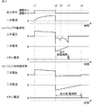
まず、本願の発明者等は、前記課題の解決手段を検討し、気筒休止システムを備えた内燃機関において、バルブが作動状態と非作動状態とで燃焼室の圧力や流動に差があることに着目し、この差が燃焼室に配設された点火プラグによる点火放電の状態である点火放電時間に関係することを実験により得た(図6参照)。
First, the inventors of the present application have studied the means for solving the above problems, and in an internal combustion engine equipped with a cylinder deactivation system, there is a difference in the pressure and flow of the combustion chamber between the operating state and the non-operating state. Paying attention, it was experimentally obtained that this difference is related to the ignition discharge time which is the state of ignition discharge by the ignition plug disposed in the combustion chamber (see FIG. 6).
図6(a)〜(c)において、実線がバルブ作動状態であり、破線がバルブ休止状態である。図6(a)はバルブ作動状態と非作動状態におけるバルブリフト量を示しており、図6(b)はバルブ作動状態と非作動状態における燃焼室の圧力を示しており、図6(c)はバルブ作動状態と非作動状態における各クランク角での点火に対する点火放電時間を示している。 In FIGS. 6A to 6C, the solid line is the valve operating state, and the broken line is the valve resting state. FIG. 6A shows the valve lift amount in the valve operating state and the non-operating state, and FIG. 6B shows the pressure in the combustion chamber in the valve operating state and the non-operating state. Indicates the ignition discharge time for ignition at each crank angle in the valve operating state and the non-operating state.
まず、バルブ作動状態では、吸気や排気による流動が発生する。これにより点火プラグ電極間の点火放電が流される。流された分、点火放電経路が長くなり、点火放電維持電圧も高くなる。一方、バルブ非作動状態では、常にバルブリフト量がゼロであるため(図6(a)参照)、吸気や排気による流動が発生しない。これにより点火プラグ電極間の点火放電が流されない。流されない分、点火放電経路が短くなり、点火放電維持電圧もバルブ作動状態に比べて低くなる。 First, in the valve operating state, flow due to intake or exhaust occurs. As a result, an ignition discharge flows between the spark plug electrodes. The flow of the ignition discharge becomes longer and the ignition discharge sustaining voltage becomes higher. On the other hand, in the valve non-operating state, the valve lift amount is always zero (see FIG. 6A), so that no flow due to intake or exhaust occurs. Thereby, the ignition discharge between the spark plug electrodes does not flow. Since the current is not flown, the ignition discharge path is shortened, and the ignition discharge sustaining voltage is also lower than that in the valve operating state.
点火プラグに与えられるエネルギが同じである場合、点火放電維持電圧が高いほど消費されるエネルギも大きいため、与えられたエネルギが失われるまでの点火放電時間は短くなる。つまり、バルブ作動状態では、バルブ非作動状態に比べて点火放電時間が短くなる(図6(c)参照)。 When the energy applied to the spark plug is the same, the higher the ignition discharge maintenance voltage is, the more energy is consumed. Therefore, the ignition discharge time until the applied energy is lost becomes shorter. That is, the ignition discharge time is shorter in the valve operating state than in the valve non-operating state (see FIG. 6C).
また、バルブ作動状態では、圧縮TDCで燃焼室の圧力が最大となり、排気TDCでは燃焼室の圧力は略大気圧となる。一方、バルブ非作動状態では、圧縮TDCと排気TDCとで燃焼室の圧力は略同じであり、かつ、燃焼室内の気体がピストンリングとシリンダライナの隙間等から抜けるため、バルブ作動状態における燃焼室の圧力に比べて低くなる(図6(b)参照)。 In the valve operating state, the pressure in the combustion chamber becomes maximum at the compression TDC, and the pressure in the combustion chamber becomes substantially atmospheric pressure at the exhaust TDC. On the other hand, in the valve non-operating state, the pressure in the combustion chamber is substantially the same between the compression TDC and the exhaust TDC, and the gas in the combustion chamber escapes from the gap between the piston ring and the cylinder liner. (See FIG. 6B).
点火プラグによる絶縁破壊電圧は、パッシェンの法則で知られている様に圧力に依存するため、燃焼室の圧力が高いほど絶縁破壊電圧も高くなる。点火プラグに与えられるエネルギが同じである場合、絶縁破壊電圧が高いほど消費されるエネルギも大きいため、与えられたエネルギが失われるまでの点火放電時間は短くなる。このため、バルブ作動状態では、圧縮TDC近傍で点火放電時間が短い傾向となり、バルブ非作動状態では圧縮TDCおよび排気TDCで点火放電時間が短い傾向となる(図6(c)参照)。 Since the breakdown voltage due to the spark plug depends on the pressure as known from Paschen's law, the breakdown voltage increases as the pressure in the combustion chamber increases. When the energy applied to the spark plug is the same, the higher the dielectric breakdown voltage, the greater the energy consumed, so the ignition discharge time until the applied energy is lost becomes shorter. For this reason, the ignition discharge time tends to be short in the vicinity of the compression TDC in the valve operating state, and the ignition discharge time tends to be short in the compression TDC and exhaust TDC in the valve non-operation state (see FIG. 6C).
以上の特性を用いて、点火放電時間によってバルブ状態を判定することができる。 Using the above characteristics, the valve state can be determined based on the ignition discharge time.
以下、図に基づいて、本発明の実施の形態1について詳細に説明する。図1は本発明の実施の形態1に係る内燃機関を概略的に示す構成図と本発明の実施の形態1による内燃機関の制御装置の構成を示すブロック図である。
Hereinafter,
図1において、内燃機関100における気筒1の燃焼室2には、吸気バルブ3と排気バルブ4とピストン5、更に、燃焼室2内を臨むようにして、点火プラグ6とインジェクタ7とが備えられている。
In FIG. 1, a
吸気バルブ3および排気バルブ4は吸気バルブ可変動弁装置23および排気バルブ可変動弁装置24によってそれぞれ駆動され、吸気バルブ可変動弁装置23および排気バルブ可変動弁装置24は吸気バルブ3および排気バルブ4のリフト量や作動角等のバルブ特性をそれぞれ変更する。本発明の実施の形態1においては、吸気バルブ3および排気バルブ4は、気筒休止制御手段101からの要求に基づいてバルブ作動手段102により吸気バルブ3および排気バルブ4の少なくともどちらか一方のバルブを作動もしくは非作動(リフト量=0)とする。
The
ピストン5はコネクティングロッド15によってクランク軸14に連結されている。このクランク軸14の回転角(クランク角)を検出するため気筒1内にクランク角センサ13が備えられている。
The
また、吸気通路8に設けられた電子制御スロットル9により、燃焼室2に供給する吸入空気量が調整される。電子制御スロットル9は、スロットルバルブ9aと、これを駆動するモータ9b、スロットルバルブ9aの開度を検出するスロットル開度センサ9cとから構成されている。
An intake air amount supplied to the
エンジン制御ユニット(以下、ECUと称す)10は、アクセルペダル11の操作量を検出するアクセルポジションセンサ12の出力信号を取得して、モータ9bに制御信号を送り、スロットル開度センサ9cからのスロットルバルブ開度信号に基づいて、スロットルバルブ9aを適切な開度に制御する。
An engine control unit (hereinafter referred to as ECU) 10 acquires an output signal of an
また、ECU10は、アクセルポジションセンサ12、クランク角センサ13、エアフローセンサ16、空燃比センサ21、のほか、各種センサ類(図示せず)からの出力信号を取得して、点火時期や燃料噴射量などを決定する。そして、それらの各決定値に基づいて、インジェクタ7を駆動して燃料を燃焼室2に噴射供給し、点火制御手段103により点火プラグ6に接続された点火コイル19を駆動することで点火プラグ6のプラグギャップから火花を放電させる。
The
本発明の実施の形態1においては、気筒休止制御手段101は、内燃機関の少なくとも一つの気筒を運転または休止させるものであって、気筒休止制御手段101から気筒休止が要求されていない場合には第1の点火制御手段104により第1の点火制御を実施し、且つ気筒休止制御手段101から気筒休止が要求されている場合は第2の点火制御手段105により第2の点火制御を実施する。また本発明の実施の形態1においては、点火コイル19はイオン電流検出機能を備えており、ECU10は、第2の点火制御手段105による点火が実施されている場合に、点火コイル19からのイオン電流出力信号に基づいて放電時間算出手段106により放電時間を算出する。即ち、気筒休止と通常運転で点火制御方法を切換える。詳細については後述するが、点火放電時間に基づいてバルブ状態検出を行う場合、点火コイルの通電エネルギが等しくなるように通電開始時期および通電終了時期を算出する。
In the first embodiment of the present invention, the cylinder deactivation control means 101 operates or deactivates at least one cylinder of the internal combustion engine, and when the cylinder deactivation control means 101 does not request cylinder deactivation. The first
さらに、ECU10は、バルブ状態判定手段107により、算出された放電時間に基づいてバルブが作動状態か非作動状態かを判定し、判定結果を気筒休止制御手段101へ出力する。
Further, the
エアクリーナ17によって塵やごみが除去された吸入空気は、エアフローセンサ16で流量が計測された後、電子制御スロットル9を通過してサージタンク18へと導かれ、更に、サージタンク18から吸気バルブ3を通って燃焼室2に導入される。燃焼室2内に導入された吸入空気とインジェクタ7から噴射された燃料とが混ざりあって混合気が形成され、点火プラグ6の火花放電によって混合気が着火されて燃焼する。なお、本発明の実施の形態1においては、一部の気筒は気筒休止要求に基づいて燃料噴射を停止するため、燃焼は発生せず火花放電のみが発生する状態となる。
The intake air from which dust and dirt have been removed by the
混合気の燃焼圧力はピストン5に伝えられてピストン5を往復運動させる。ピストン5の往復運動はコネクティングロッド15を介してクランク軸14に伝えられ、ここで回転運動に変換されて、内燃機関100の出力として取り出される。燃焼後の混合気は排気ガスとなり、排気バルブ4を通って排気通路20へ排出される。排気通路20の集合部には排気中の空燃比を検出する空燃比センサ21が備えられている。また、排気通路20の集合部より下流側には、排気中の有害成分を浄化するための三元触媒器22が備えられている。
The combustion pressure of the air-fuel mixture is transmitted to the
次に、本発明の実施の形態1に係る内燃機関の制御装置、特に、バルブ状態判定の具体的な動作について図5のタイミングチャートを用いて説明する。図5の「(a)バルブ作動状態」はバルブ作動状態における点火放電挙動を示しており、図5の「(b)バルブ非作動状態」はバルブ非作動状態における点火放電挙動を示している。横軸は時間を示す。 Next, a specific operation of the control apparatus for an internal combustion engine according to the first embodiment of the present invention, in particular, the valve state determination will be described with reference to the timing chart of FIG. “(A) Valve operation state” in FIG. 5 shows the ignition discharge behavior in the valve operation state, and “(b) Valve non-operation state” in FIG. 5 shows the ignition discharge behavior in the valve non-operation state. The horizontal axis indicates time.
まず、ECU10内の第2の点火制御手段105は、吸気バルブ状態判定および排気バルブ状態判定のために点火コイル19に対して少なくとも各1回は点火指示信号を発生させる。点火指示信号が通電オフから通電オンの状態になると(t1)、点火コイル19の一次コイルに一次電流が流れることで点火コイル19はエネルギの蓄積を開始し、点火指示信号が通電オンから通電オフの状態になると(t2)、二次コイルに高電圧(二次電圧)が生成される(t2以降)。この二次電圧は、点火プラグ6の第一の電極へと伝えられ、第一の電極と第二の電極の間に絶縁破壊が発生し、点火放電電流が流れ始め、蓄積したエネルギの分だけ点火放電が持続される。
First, the second ignition control means 105 in the
前述したようにバルブ作動状態では、吸気や排気による流動により点火プラグ電極間の点火放電が流された分、点火放電経路が長くなり、図5の「(a)バルブ作動状態」に示すように、二次電圧(点火放電維持電圧)が負の方向に高くなる(t2〜t3)。点火放電経路が長くなり過ぎると途切れることがあるが(t3)、再度絶縁破壊が発生し、二次電圧(点火放電維持電圧)が負の方向に高くなることもある(t3〜t4)。 As described above, in the valve operating state, the ignition discharge path becomes longer by the amount of ignition discharge between the spark plug electrodes caused by the flow caused by intake or exhaust, as shown in “(a) Valve operating state” in FIG. The secondary voltage (ignition discharge sustaining voltage) increases in the negative direction (t2 to t3). If the ignition discharge path becomes too long, it may be interrupted (t3), but dielectric breakdown will occur again, and the secondary voltage (ignition discharge sustaining voltage) may increase in the negative direction (t3 to t4).
蓄積したエネルギが少なくなり、点火放電電流が点火放電を維持できるレベルを下回ると点火放電が終了する(t4)。その際、残留エネルギで再び絶縁破壊を発生させようとするができず、点火コイル19の二次コイルのインダクタンスや二次コイル側の浮遊容量やコンデンサによるLC共振ノイズ(容量電流)が発生する。このLC共振ノイズはイオン電流に流れるため、正方向の電流のみが放電終了時の電流として検出される。なお、LC共振ノイズの発生幅は数十〜数百[μsec]程度である。通電オフ(t2)からLC共振ノイズが検出されるタイミング(t4)までの時間がバルブ作動状態における点火放電時間となる。
When the accumulated energy decreases and the ignition discharge current falls below a level at which the ignition discharge can be maintained, the ignition discharge ends (t4). At that time, it is not possible to cause dielectric breakdown again due to the residual energy, and inductance of the secondary coil of the
一方、バルブ非作動状態では常にバルブリフト量がゼロであり、吸気や排気による流動が発生せず点火放電もほとんど流されないため、点火放電経路も長くならず、図5の「(b)バルブ非作動状態」に示すように、点火放電維持電圧はバルブ作動状態のように負の方向に高くならない(t2〜t5)。そのため、バルブ作動状態の放電終了タイミング(t4)より後のタイミング(t5)でLC共振ノイズが検出される。通電オフ(t2)からLC共振ノイズが検出されるタイミング(t5)までの時間がバルブ非作動状態における点火放電時間となる。 On the other hand, the valve lift amount is always zero in the non-operating state of the valve, the flow due to intake or exhaust does not occur, and the ignition discharge hardly flows. Therefore, the ignition discharge path is not lengthened. As shown in the “operating state”, the ignition discharge maintaining voltage does not increase in the negative direction as in the valve operating state (t2 to t5). Therefore, LC resonance noise is detected at a timing (t5) after the discharge end timing (t4) in the bulb operating state. The time from energization OFF (t2) to the timing (t5) at which LC resonance noise is detected is the ignition discharge time in the valve non-operating state.
つまり、バルブ作動状態における点火放電時間(t4−t2)よりもバルブ非作動状態における点火放電時間(t5−t2)が長くなることを用いて、バルブ状態を判定することができる。 That is, the valve state can be determined using the fact that the ignition discharge time (t5-t2) in the valve non-operation state is longer than the ignition discharge time (t4-t2) in the valve operation state.
次に、図2のフローチャートを用いて、本発明の実施の形態1による内燃機関の制御装置の具体的な処理について説明する。なお、この処理は所定の時間毎に繰り返し実行される。 Next, specific processing of the control device for an internal combustion engine according to the first embodiment of the present invention will be described using the flowchart of FIG. This process is repeatedly executed every predetermined time.
図2において、先ず、ステップS201では、前述した気筒休止制御手段101から気筒休止の要求があるか否かを判定する。気筒休止の要求がある(ステップS201でYes)場合はステップS202に進み、気筒休止の要求がない(ステップS201でNo)場合はステップS205に進む。以降では先ず、ステップS201でNoの場合の以降の処理について説明する。 In FIG. 2, first, in step S201, it is determined whether or not there is a request for cylinder deactivation from the cylinder deactivation control means 101 described above. If there is a request for cylinder deactivation (Yes in step S201), the process proceeds to step S202. If there is no request for cylinder deactivation (No in step S201), the process proceeds to step S205. Hereinafter, first, the subsequent processing in the case of No in step S201 will be described.
ステップS201でNoの場合、つまり、気筒休止要求がなく全ての気筒を運転(燃焼)させる場合、ステップS205にて第1の点火制御手段104による第1の点火制御が実行される。前述したように、通常、混合気の着火のために行われる点火制御では、内燃機関の出力性能および燃焼効率を最適とするために点火時期を基準に点火コイルへの通電が行われる。 In the case of No in step S201, that is, when there is no cylinder deactivation request and all cylinders are operated (combusted), the first ignition control by the first ignition control means 104 is executed in step S205. As described above, in the ignition control that is normally performed for the ignition of the air-fuel mixture, the ignition coil is energized based on the ignition timing in order to optimize the output performance and combustion efficiency of the internal combustion engine.
ここで、第1の点火制御手段104の動作について、図3のタイミングチャートを用いて説明する。図3(a)は、t0〜t2の間で内燃機関の運転条件の変化がない場合を示しており、図3(b)は基準となる回転速度を算出するタイミング(t0)よりも実際に通電を行うタイミング(t1〜t2)の方が内燃機関の回転速度が遅くなった場合を示しており、図3(c)は基準となる回転速度を算出するタイミング(t0)よりも実際に通電を行うタイミング(t1〜t2)のほうが内燃機関の回転速度が速くなった場合を示している。横軸は時間を示す。 Here, the operation of the first ignition control means 104 will be described using the timing chart of FIG. FIG. 3 (a) shows a case where there is no change in the operating condition of the internal combustion engine between t0 and t2, and FIG. 3 (b) is actually more than the timing (t0) for calculating the reference rotational speed. The timing of energization (t1 to t2) shows the case where the rotational speed of the internal combustion engine is slower, and FIG. 3 (c) is actually energized than the timing (t0) for calculating the reference rotational speed. The timing (t1 to t2) at which the operation is performed shows a case where the rotational speed of the internal combustion engine becomes faster. The horizontal axis indicates time.
第1の点火制御手段104では、t0のタイミングにおいて、点火時期CAigaおよび通電時間Tdwlaを取得し、また予め定められた所定のクランク角度区間(回転角度)CA0に対する経過時間T0を用いてクランク角速度CA0/T0を算出する。便宜上、図3(a)〜(c)においてはクランク角度区間CA0における経過時間T0の表示を併記している。これらの値を用いて、同タイミングにて、次式(1)に基づいて点火コイル19への通電開始時期CAonを算出する。なお、通電終了時期CAoffは点火時期CAigと同じである。
In the first
CAon=CAiga+Tdwla×(CA0/T0) ・・・(1) CAon = CAiga + Tdwla × (CA0 / T0) (1)
第1の点火制御手段104によると、通電終了時期CAoffは点火時期CAigaと等しいため、予め定められた所定のタイミングで混合気に着火することができ、出力性能および燃焼効率を最適とすることができる。一方、運転条件が変化するような場合には、実際の通電時間(t2−t1)と要求された通電時間Tdwlaとは異なる。 According to the first ignition control means 104, the energization end timing CAoff is equal to the ignition timing CAiga. Therefore, the air-fuel mixture can be ignited at a predetermined timing, and the output performance and the combustion efficiency can be optimized. it can. On the other hand, when the operating condition changes, the actual energization time (t2-t1) and the requested energization time Tdwla are different.
図3(b)では、基準となる回転速度を算出したタイミングt0よりも実際に点火コイル19への通電を行ったタイミングt1〜t2での回転速度が遅くなったため、即ち前述の式(1)におけるクランク角速度CA0/T0が小さくなるので通電開始時期CAonが早くなり、実際の通電時間(t2−t1)が要求された通電時間Tdwlaよりも長くなっている。
In FIG. 3B, the rotational speed at the timings t1 to t2 at which the
図3(c)では、基準となる回転速度を算出したタイミングt0よりも実際に点火コイル19への通電を行ったタイミングt1〜t2での回転速度が速くなったため、即ち前述の式(1)におけるクランク角速度CA0/T0が大きくなるので通電開始時期CAonが遅くなり、実際の通電時間(t2−t1)が要求された通電時間Tdwlaよりも短くなっている。
In FIG. 3C, the rotational speed at the timings t1 to t2 at which the
このように、気筒休止が要求されているか否かで点火制御手段を切換えることができるため、それぞれの運転状態における点火の目的に応じて点火制御を実施することが可能である。 Thus, since the ignition control means can be switched depending on whether or not cylinder deactivation is required, it is possible to perform ignition control according to the purpose of ignition in each operating state.
また、気筒休止が要求されていない場合に点火時期を基準に点火コイルへの通電を行うことで、点火時期と通電終了時期が等しくなるため、所定のタイミングで確実に混合気に着火することができる。 In addition, when the cylinder deactivation is not required, by energizing the ignition coil based on the ignition timing, the ignition timing and the energization end timing become equal, so that the air-fuel mixture can be reliably ignited at a predetermined timing. it can.
図2に戻って、ステップS201でYesの場合、つまり、気筒休止が要求されて一部気筒の運転を休止させる場合、休止される気筒に対してステップS202にて第2の点火制御手段105による第2の点火制御が実行される。前述したように、バルブ状態判定用の点火制御では、点火プラグ6へ与えられるエネルギ、つまり、通電時間が等しくなるように点火コイル19への通電が行われる。
Returning to FIG. 2, in the case of Yes in step S <b> 201, that is, when the operation of some cylinders is stopped due to the request for cylinder deactivation, the second
ここで、第2の点火制御手段105による第2の点火制御の動作について、図4のタイミングチャートを用いて説明する。図4(a)は、t0〜t2の間で内燃機関の運転条件の変化がない場合を示しており、図4(b)は基準となる回転速度を算出するタイミング(t0)よりも実際に通電を行うタイミング(t1〜t2)のほうが内燃機関の回転速度が遅くなった場合を示しており、図4(c)は基準となる回転速度を算出するタイミング(t0)よりも実際に通電を行うタイミング(t1〜t2)のほうが内燃機関の回転速度が速くなった場合を示している。横軸は時間を示す。 Here, the operation of the second ignition control by the second ignition control means 105 will be described using the timing chart of FIG. FIG. 4A shows a case where there is no change in the operating condition of the internal combustion engine between t0 and t2, and FIG. 4B is actually more than the timing (t0) for calculating the reference rotational speed. The timing of energization (t1 to t2) shows a case in which the rotational speed of the internal combustion engine becomes slower. FIG. 4C shows the actual energization than the timing (t0) for calculating the reference rotational speed. The timing (t1-t2) to perform shows the case where the rotational speed of an internal combustion engine became quick. The horizontal axis indicates time.
第2の点火制御手段105では、t0のタイミングにおいて、点火時期CAigbおよび通電時間Tdwlbを取得し、また予め定められた所定のクランク角度区間(回転角度)CA0に対する経過時間T0を用いてクランク角速度CA0/T0を算出する。便宜上、図4(a)〜(c)においてはクランク角度区間CA0における経過時間T0の表示を併記している。これら値を用いて、同タイミングにて、前述した式(1)に基づいて点火コイル19への通電開始時期CAonを算出する。なお、通電開始時期CAonから通電時間Tdwlb経過後を通電終了時期CAoffとする。
In the second
第2の点火制御手段105によると、図4(b)および図4(c)のように回転速度が変化するような場合にも、前述の図3(b)、図3(c)と同様に、通電開始時期CAonは変化するが、実際の通電時間(t2−t1)は要求された通電時間Tdwlbと等しいため、点火プラグに与えるエネルギが等しくなり、点火放電時間によりバルブ状態を精度良く判定することができる。一方、通電終了時期CAoffは点火時期CAigbと異なる。 According to the second ignition control means 105, even when the rotational speed changes as shown in FIGS. 4B and 4C, the same as in FIGS. 3B and 3C described above. Although the energization start timing CAon changes, the actual energization time (t2-t1) is equal to the requested energization time Tdwlb, so the energy applied to the spark plug is equal, and the valve state is accurately determined by the ignition discharge time. can do. On the other hand, the energization end timing CAoff is different from the ignition timing CAig b .
ここで、第2の点火制御手段105にて設定される通電時間Tdwlbは、前述した第1の点火制御手段104にて設定される通電時間Tdwlaよりも短く設定する。これにより、点火コイルおよび点火プラグへ与えられるエネルギが減少し、点火コイルおよび点火プラグの劣化を抑制することができる。 Here, the energization time Tdwlb set by the second ignition control means 105 is set shorter than the energization time Tdwla set by the first ignition control means 104 described above. Thereby, the energy given to an ignition coil and a spark plug reduces, and deterioration of an ignition coil and a spark plug can be suppressed.
また、予め設定される回転速度の変化幅に基づいて、点火時期CAigbと通電終了時期CAoffが予め定められた所定の範囲内となるように通電時間を設定する。例えば、回転速度の変化幅が200[r/min]とした場合、点火時期CAigbと通電終了時期CAoffとの差を3[degCA]以内とするためには、通電時間Tdwlbを2.5[msec]以下に設定すれば良い。これにより、通電時間を基準として点火を行う場合においても予め定められた所定のタイミングで点火を行うことができるため、前述した点火放電時間特性に基づいてバルブ状態を精度良く判定することができる。 Further, the energization time is set so that the ignition timing CAigb and the energization end timing CAoff are within a predetermined range based on the change width of the preset rotation speed. For example, when the change speed of the rotation speed is 200 [r / min], in order to set the difference between the ignition timing CAigb and the energization end timing CAoff within 3 [degCA], the energization time Tdwlb is set to 2.5 [msec]. The following should be set. As a result, even when ignition is performed based on the energization time, ignition can be performed at a predetermined timing, so that the valve state can be accurately determined based on the ignition discharge time characteristics described above.
図2に戻って、ステップS203では、前述したように通電終了時期からLC共振ノイズが検出されるタイミングまでの時間を点火放電時間として算出する。 Returning to FIG. 2, in step S203, as described above, the time from the end of energization to the timing at which the LC resonance noise is detected is calculated as the ignition discharge time.
ステップS204では、ステップS203で算出された点火放電時間に基づいてバルブが作動しているか否かを判定して処理を終了する。 In step S204, it is determined whether the valve is operating based on the ignition discharge time calculated in step S203, and the process ends.
このように、気筒休止が要求されている場合に通電時間を基準に点火コイルへの通電を行うことで、内燃機関の運転状態によらず点火コイルの通電時間、つまり、点火プラグへ与えられるエネルギが等しくなるため、バルブの作動状態のみが点火放電時間に影響し、バルブ状態を精度良く判定することができる。 In this way, when the cylinder deactivation is requested, by energizing the ignition coil based on the energization time, the energization time of the ignition coil, that is, the energy given to the ignition plug, regardless of the operating state of the internal combustion engine. Therefore, only the operating state of the valve affects the ignition discharge time, and the valve state can be accurately determined.
また、バルブ状態判定用の点火を行う場合に通電時間を短く設定することで、点火コイルおよび点火プラグへ与えられるエネルギが減少し、点火コイルおよび点火プラグの劣化および摩耗を抑制することができる。 In addition, by setting the energization time short when performing ignition for determining the valve state, energy applied to the ignition coil and the spark plug is reduced, and deterioration and wear of the ignition coil and the spark plug can be suppressed.
更に、通電時間を基準に点火コイルへの通電を行う場合に、予め設定した内燃機関の運転状態の変化幅に基づいて、点火時期と通電終了時期が所定の範囲内となるように通電時間を設定することで、所定のタイミングで点火を行うことができ、バルブ状態を精度良く判定することができる。 Further, when energizing the ignition coil based on the energization time, the energization time is set so that the ignition timing and the energization end timing are within a predetermined range based on a preset change range of the operating state of the internal combustion engine. By setting, ignition can be performed at a predetermined timing, and the valve state can be accurately determined.
以上により、本発明の実施の形態1による内燃機関の制御装置によれば、気筒休止が要求されている場合に、気筒休止を行う一部気筒に対して通電時間を基準として点火コイルへの通電を行う。これにより、点火放電時間によりバルブ状態を精度良く判定することができる。 As described above, according to the control apparatus for an internal combustion engine according to the first embodiment of the present invention, when cylinder deactivation is requested, energization to the ignition coil is performed based on the energization time for some cylinders that perform cylinder deactivation. I do. As a result, the valve state can be accurately determined from the ignition discharge time.
本発明は、その発明の範囲内において、実施の形態を適宜、変更、省略することが可能である。 In the present invention, the embodiments can be appropriately changed or omitted within the scope of the invention.
1 気筒、2 燃焼室、3 吸気バルブ、4 排気バルブ、6 点火プラグ、19 点火コイル、100 内燃機関、101 気筒休止制御手段、 102 バルブ作動手段、103 点火制御手段、104 第1の点火制御手段、105 第2の点火制御手段、106 放電時間算出手段、107 バルブ状態判定手段。 1 cylinder, 2 combustion chamber, 3 intake valve, 4 exhaust valve, 6 spark plug, 19 ignition coil, 100 internal combustion engine, 101 cylinder deactivation control means, 102 valve actuation means, 103 ignition control means, 104 first ignition control means , 105 second ignition control means, 106 discharge time calculation means, 107 valve state determination means.
Claims (5)
前記気筒休止制御手段からの要求に基づいて、内燃機関に配設された吸気バルブおよび排気バルブの少なくともどちらか一方を作動もしくは非作動させるバルブ作動手段と、
予め設定される点火時期と通電時間に基づいて前記内燃機関に配設された点火コイルに通電し、前記内燃機関の燃焼室に配設された点火プラグを点火放電させる点火制御手段と、
前記点火放電の継続時間である点火放電時間を算出する点火放電時間算出手段と、
前記点火放電時間算出手段により検出された点火放電時間に基づいて前記吸気バルブおよび排気バルブの少なくともどちらか一方の作動状態を判定するバルブ状態判定手段と、
を備え、
前記点火制御手段は、前記気筒休止制御手段から気筒休止が要求されていない場合には前記点火時期を基準として前記点火プラグの点火放電を行う第1の点火制御手段と前記気筒休止制御手段から気筒休止が要求された場合には前記通電時間を基準として前記点火プラグの点火放電行う第2の点火制御手段を有することを特徴とする内燃機関の制御装置。 Cylinder deactivation control means for operating or deactivating at least one cylinder of the internal combustion engine;
Based on a request from the cylinder deactivation control means, valve operating means for operating or inactivating at least one of an intake valve and an exhaust valve disposed in the internal combustion engine;
Ignition control means for energizing an ignition coil disposed in the internal combustion engine based on a preset ignition timing and energization time and igniting and discharging a spark plug disposed in a combustion chamber of the internal combustion engine;
Ignition discharge time calculating means for calculating an ignition discharge time which is a duration of the ignition discharge;
Valve state determining means for determining an operating state of at least one of the intake valve and the exhaust valve based on the ignition discharge time detected by the ignition discharge time calculating means;
With
When the cylinder deactivation control unit does not request cylinder deactivation, the ignition control unit includes a first ignition control unit that performs ignition discharge of the ignition plug with reference to the ignition timing, and a cylinder deactivation control unit 2. A control apparatus for an internal combustion engine, comprising: second ignition control means for performing ignition discharge of the spark plug with reference to the energization time when a stop is requested.
Priority Applications (4)
| Application Number | Priority Date | Filing Date | Title |
|---|---|---|---|
| JP2014213378A JP5911547B1 (en) | 2014-10-20 | 2014-10-20 | Control device for internal combustion engine |
| US14/640,481 US10280848B2 (en) | 2014-10-20 | 2015-03-06 | Internal combustion engine control apparatus |
| DE102015205014.9A DE102015205014B4 (en) | 2014-10-20 | 2015-03-19 | Internal combustion engine control device |
| CN201510347173.5A CN106194448B (en) | 2014-10-20 | 2015-06-19 | The control device of internal combustion engine |
Applications Claiming Priority (1)
| Application Number | Priority Date | Filing Date | Title |
|---|---|---|---|
| JP2014213378A JP5911547B1 (en) | 2014-10-20 | 2014-10-20 | Control device for internal combustion engine |
Publications (2)
| Publication Number | Publication Date |
|---|---|
| JP5911547B1 true JP5911547B1 (en) | 2016-04-27 |
| JP2016079920A JP2016079920A (en) | 2016-05-16 |
Family
ID=55638176
Family Applications (1)
| Application Number | Title | Priority Date | Filing Date |
|---|---|---|---|
| JP2014213378A Expired - Fee Related JP5911547B1 (en) | 2014-10-20 | 2014-10-20 | Control device for internal combustion engine |
Country Status (4)
| Country | Link |
|---|---|
| US (1) | US10280848B2 (en) |
| JP (1) | JP5911547B1 (en) |
| CN (1) | CN106194448B (en) |
| DE (1) | DE102015205014B4 (en) |
Families Citing this family (5)
| Publication number | Priority date | Publication date | Assignee | Title |
|---|---|---|---|---|
| US10167787B1 (en) * | 2018-01-18 | 2019-01-01 | Ford Global Technologies, Llc | Systems and methods for preventing spark plug fouling in a variable displacement engine |
| JP7107081B2 (en) * | 2018-08-07 | 2022-07-27 | トヨタ自動車株式会社 | Control device for internal combustion engine |
| JP2020051374A (en) * | 2018-09-28 | 2020-04-02 | 本田技研工業株式会社 | Cylinder deactivation switching device |
| JP7468247B2 (en) * | 2020-08-21 | 2024-04-16 | 株式会社デンソー | Ignition device for internal combustion engines |
| CN115030852B (en) * | 2021-09-27 | 2023-12-12 | 长城汽车股份有限公司 | Engine control method and device and vehicle |
Family Cites Families (19)
| Publication number | Priority date | Publication date | Assignee | Title |
|---|---|---|---|---|
| JPS61294167A (en) * | 1985-06-24 | 1986-12-24 | Nippon Denso Co Ltd | Ignitor for internal-combustion engine |
| DE19963638A1 (en) * | 1999-12-29 | 2001-07-12 | Bosch Gmbh Robert | Monitoring function of cylinder cut-off for multicylinder internal combustion engines involves comparing signals representing engine air flow, assessing discrepancy as functional fault |
| WO2003064837A1 (en) * | 2002-01-31 | 2003-08-07 | Mazda Motor Corporation | Control device for spark-ignition engine |
| US6922628B2 (en) * | 2003-11-26 | 2005-07-26 | Visteon Global Technologies, Inc. | IC engine diagnostic system using the peak and integration ionization current signals |
| US7072758B2 (en) * | 2004-03-19 | 2006-07-04 | Ford Global Technologies, Llc | Method of torque control for an engine with valves that may be deactivated |
| US7194993B2 (en) * | 2004-03-19 | 2007-03-27 | Ford Global Technologies, Llc | Starting an engine with valves that may be deactivated |
| DE102004014369A1 (en) * | 2004-03-24 | 2005-10-13 | Robert Bosch Gmbh | Method for controlling an internal combustion engine |
| WO2007140132A2 (en) * | 2006-05-25 | 2007-12-06 | Gm Global Technology Operations, Inc. | Controlling transition between hcci and si combustion |
| JP4654994B2 (en) * | 2006-07-11 | 2011-03-23 | マツダ株式会社 | Diagnostic device for intake flow control valve |
| JP4492710B2 (en) * | 2008-02-08 | 2010-06-30 | トヨタ自動車株式会社 | Control device and control method for internal combustion engine |
| JP4792478B2 (en) * | 2008-02-28 | 2011-10-12 | トヨタ自動車株式会社 | Control device for internal combustion engine |
| JP2009270492A (en) | 2008-05-08 | 2009-11-19 | Denso Corp | Failure diagnosis device of cylinder deactivation system |
| JP5384413B2 (en) * | 2010-03-31 | 2014-01-08 | 本田技研工業株式会社 | Internal combustion engine with valve deactivation mechanism |
| JP5556589B2 (en) | 2010-10-27 | 2014-07-23 | トヨタ自動車株式会社 | Fault detection device for valve stop mechanism |
| JP5728926B2 (en) * | 2010-12-16 | 2015-06-03 | いすゞ自動車株式会社 | Engine control device |
| DE102012210303B4 (en) * | 2012-06-19 | 2014-05-15 | Ford Global Technologies, Llc | A spark-ignited multi-cylinder internal combustion engine with partial shutdown and method for operating such an internal combustion engine |
| US9145822B2 (en) * | 2012-07-16 | 2015-09-29 | Ford Global Technologies, Llc | Method and device for controlling a four-stroke internal combustion engine |
| US9567928B2 (en) * | 2012-08-07 | 2017-02-14 | GM Global Technology Operations LLC | System and method for controlling a variable valve actuation system to reduce delay associated with reactivating a cylinder |
| JP5837127B2 (en) * | 2014-04-21 | 2015-12-24 | 三菱電機株式会社 | Control device for internal combustion engine with cylinder deactivation mechanism |
-
2014
- 2014-10-20 JP JP2014213378A patent/JP5911547B1/en not_active Expired - Fee Related
-
2015
- 2015-03-06 US US14/640,481 patent/US10280848B2/en active Active
- 2015-03-19 DE DE102015205014.9A patent/DE102015205014B4/en not_active Expired - Fee Related
- 2015-06-19 CN CN201510347173.5A patent/CN106194448B/en not_active Expired - Fee Related
Also Published As
| Publication number | Publication date |
|---|---|
| CN106194448A (en) | 2016-12-07 |
| CN106194448B (en) | 2019-06-14 |
| DE102015205014B4 (en) | 2020-09-03 |
| DE102015205014A1 (en) | 2016-04-21 |
| US20160108824A1 (en) | 2016-04-21 |
| JP2016079920A (en) | 2016-05-16 |
| US10280848B2 (en) | 2019-05-07 |
Similar Documents
| Publication | Publication Date | Title |
|---|---|---|
| JP5911547B1 (en) | Control device for internal combustion engine | |
| US9341134B2 (en) | Control apparatus for internal combustion engine | |
| JP5837127B2 (en) | Control device for internal combustion engine with cylinder deactivation mechanism | |
| JP4980807B2 (en) | Control device for internal combustion engine | |
| US9624862B2 (en) | Control apparatus for internal combustion engine | |
| US11067052B2 (en) | Device for controlling internal combustion engine and method for controlling internal combustion engine | |
| JP5950708B2 (en) | Control device for spark ignition internal combustion engine | |
| JP6187709B2 (en) | Control device for internal combustion engine | |
| CN102301115B (en) | Device and method for operating an internal combustion engine | |
| JP6411951B2 (en) | Control device for internal combustion engine | |
| JP2013231372A (en) | Internal combustion engine control device | |
| KR20160024079A (en) | Control apparatus and method for variable cylinder de-activation engine | |
| JP5896839B2 (en) | Control device for internal combustion engine | |
| CN104204476B (en) | Method and apparatus for determining the cetane number of a fuel | |
| JP6748743B2 (en) | Fuel injection control device and fuel injection control method | |
| JP6384097B2 (en) | Ignition device | |
| JP5911342B2 (en) | Combustion state determination device for internal combustion engine | |
| JP2018031308A (en) | Internal combustion engine control device | |
| JP2017002855A (en) | Internal combustion engine control device | |
| JP2016050531A (en) | Control device of internal combustion engine | |
| JP6168307B2 (en) | Control device for laser ignition engine | |
| JP2015222035A (en) | Fuel injection valve control unit | |
| JP6161456B2 (en) | Control device for spark ignition internal combustion engine | |
| JPS63208647A (en) | Combustion control device for diesel engine | |
| JP2018080675A (en) | Fuel injection control device for internal combustion engine |
Legal Events
| Date | Code | Title | Description |
|---|---|---|---|
| A02 | Decision of refusal |
Free format text: JAPANESE INTERMEDIATE CODE: A02 Effective date: 20151104 |
|
| A521 | Request for written amendment filed |
Free format text: JAPANESE INTERMEDIATE CODE: A523 Effective date: 20160128 |
|
| A911 | Transfer to examiner for re-examination before appeal (zenchi) |
Free format text: JAPANESE INTERMEDIATE CODE: A911 Effective date: 20160212 |
|
| TRDD | Decision of grant or rejection written | ||
| A01 | Written decision to grant a patent or to grant a registration (utility model) |
Free format text: JAPANESE INTERMEDIATE CODE: A01 Effective date: 20160322 |
|
| A61 | First payment of annual fees (during grant procedure) |
Free format text: JAPANESE INTERMEDIATE CODE: A61 Effective date: 20160329 |
|
| R151 | Written notification of patent or utility model registration |
Ref document number: 5911547 Country of ref document: JP Free format text: JAPANESE INTERMEDIATE CODE: R151 |
|
| R250 | Receipt of annual fees |
Free format text: JAPANESE INTERMEDIATE CODE: R250 |
|
| R250 | Receipt of annual fees |
Free format text: JAPANESE INTERMEDIATE CODE: R250 |
|
| R250 | Receipt of annual fees |
Free format text: JAPANESE INTERMEDIATE CODE: R250 |
|
| R250 | Receipt of annual fees |
Free format text: JAPANESE INTERMEDIATE CODE: R250 |
|
| LAPS | Cancellation because of no payment of annual fees |