JP5897852B2 - Method and apparatus for correcting ink film thickness distribution - Google Patents
Method and apparatus for correcting ink film thickness distribution Download PDFInfo
- Publication number
- JP5897852B2 JP5897852B2 JP2011198381A JP2011198381A JP5897852B2 JP 5897852 B2 JP5897852 B2 JP 5897852B2 JP 2011198381 A JP2011198381 A JP 2011198381A JP 2011198381 A JP2011198381 A JP 2011198381A JP 5897852 B2 JP5897852 B2 JP 5897852B2
- Authority
- JP
- Japan
- Prior art keywords
- ink
- roller
- printing
- opening amount
- roller group
- Prior art date
- Legal status (The legal status is an assumption and is not a legal conclusion. Google has not performed a legal analysis and makes no representation as to the accuracy of the status listed.)
- Active
Links
- 238000000034 method Methods 0.000 title claims description 33
- 238000007639 printing Methods 0.000 claims description 278
- 238000011144 upstream manufacturing Methods 0.000 claims description 56
- 238000012937 correction Methods 0.000 claims description 36
- 238000001739 density measurement Methods 0.000 claims description 16
- 230000008878 coupling Effects 0.000 claims description 3
- 238000010168 coupling process Methods 0.000 claims description 3
- 238000005859 coupling reaction Methods 0.000 claims description 3
- 230000015654 memory Effects 0.000 description 144
- 238000004140 cleaning Methods 0.000 description 31
- 238000012545 processing Methods 0.000 description 18
- 239000007788 liquid Substances 0.000 description 13
- 238000005259 measurement Methods 0.000 description 10
- 239000000463 material Substances 0.000 description 8
- 230000008569 process Effects 0.000 description 8
- 230000002093 peripheral effect Effects 0.000 description 6
- 230000004044 response Effects 0.000 description 5
- 238000005406 washing Methods 0.000 description 5
- 238000006243 chemical reaction Methods 0.000 description 4
- 238000001514 detection method Methods 0.000 description 4
- 238000010586 diagram Methods 0.000 description 4
- 238000012360 testing method Methods 0.000 description 4
- 238000012790 confirmation Methods 0.000 description 3
- 238000009434 installation Methods 0.000 description 3
- FBOUIAKEJMZPQG-AWNIVKPZSA-N (1E)-1-(2,4-dichlorophenyl)-4,4-dimethyl-2-(1,2,4-triazol-1-yl)pent-1-en-3-ol Chemical compound C1=NC=NN1/C(C(O)C(C)(C)C)=C/C1=CC=C(Cl)C=C1Cl FBOUIAKEJMZPQG-AWNIVKPZSA-N 0.000 description 2
- 230000008859 change Effects 0.000 description 2
- 230000007246 mechanism Effects 0.000 description 2
- 239000007787 solid Substances 0.000 description 2
- WBMKMLWMIQUJDP-STHHAXOLSA-N (4R,4aS,7aR,12bS)-4a,9-dihydroxy-3-prop-2-ynyl-2,4,5,6,7a,13-hexahydro-1H-4,12-methanobenzofuro[3,2-e]isoquinolin-7-one hydrochloride Chemical compound Cl.Oc1ccc2C[C@H]3N(CC#C)CC[C@@]45[C@@H](Oc1c24)C(=O)CC[C@@]35O WBMKMLWMIQUJDP-STHHAXOLSA-N 0.000 description 1
- KNMAVSAGTYIFJF-UHFFFAOYSA-N 1-[2-[(2-hydroxy-3-phenoxypropyl)amino]ethylamino]-3-phenoxypropan-2-ol;dihydrochloride Chemical compound Cl.Cl.C=1C=CC=CC=1OCC(O)CNCCNCC(O)COC1=CC=CC=C1 KNMAVSAGTYIFJF-UHFFFAOYSA-N 0.000 description 1
- 239000003086 colorant Substances 0.000 description 1
- 239000000284 extract Substances 0.000 description 1
- 238000013100 final test Methods 0.000 description 1
- 239000010893 paper waste Substances 0.000 description 1
- 230000037452 priming Effects 0.000 description 1
- 238000011084 recovery Methods 0.000 description 1
- 230000009467 reduction Effects 0.000 description 1
- 238000007790 scraping Methods 0.000 description 1
- 238000002834 transmittance Methods 0.000 description 1
Images


Classifications
-
- B—PERFORMING OPERATIONS; TRANSPORTING
- B41—PRINTING; LINING MACHINES; TYPEWRITERS; STAMPS
- B41F—PRINTING MACHINES OR PRESSES
- B41F31/00—Inking arrangements or devices
- B41F31/02—Ducts, containers, supply or metering devices
- B41F31/04—Ducts, containers, supply or metering devices with duct-blades or like metering devices
- B41F31/045—Remote control of the duct keys
-
- B—PERFORMING OPERATIONS; TRANSPORTING
- B41—PRINTING; LINING MACHINES; TYPEWRITERS; STAMPS
- B41F—PRINTING MACHINES OR PRESSES
- B41F31/00—Inking arrangements or devices
- B41F31/30—Arrangements for tripping, lifting, adjusting, or removing inking rollers; Supports, bearings, or forks therefor
- B41F31/301—Devices for tripping and adjusting form rollers
-
- B—PERFORMING OPERATIONS; TRANSPORTING
- B41—PRINTING; LINING MACHINES; TYPEWRITERS; STAMPS
- B41F—PRINTING MACHINES OR PRESSES
- B41F33/00—Indicating, counting, warning, control or safety devices
- B41F33/0036—Devices for scanning or checking the printed matter for quality control
- B41F33/0045—Devices for scanning or checking the printed matter for quality control for automatically regulating the ink supply
-
- B—PERFORMING OPERATIONS; TRANSPORTING
- B41—PRINTING; LINING MACHINES; TYPEWRITERS; STAMPS
- B41F—PRINTING MACHINES OR PRESSES
- B41F33/00—Indicating, counting, warning, control or safety devices
- B41F33/04—Tripping devices or stop-motions
- B41F33/10—Tripping devices or stop-motions for starting or stopping operation of damping or inking units
-
- B—PERFORMING OPERATIONS; TRANSPORTING
- B41—PRINTING; LINING MACHINES; TYPEWRITERS; STAMPS
- B41P—INDEXING SCHEME RELATING TO PRINTING, LINING MACHINES, TYPEWRITERS, AND TO STAMPS
- B41P2233/00—Arrangements for the operation of printing presses
- B41P2233/10—Starting-up the machine
- B41P2233/11—Pre-inking
Landscapes
- Engineering & Computer Science (AREA)
- Quality & Reliability (AREA)
- Inking, Control Or Cleaning Of Printing Machines (AREA)
Description
この発明は、インキ供給装置におけるインキローラ群に形成されているインキ膜厚分布を補正するインキ膜厚分布の補正方法および装置に関するものである。 The present invention relates to an ink film thickness distribution correction method and apparatus for correcting an ink film thickness distribution formed on an ink roller group in an ink supply apparatus.
図32に輪転印刷機における各色の印刷ユニット内のインカー(インキ供給装置)の要部を示す。同図において、1はインキツボ、2はインキツボ1に蓄えられたインキ、3はインキツボローラ、4(4−1〜4−n)はインキツボローラ3の軸方向に複数並設して設けられたインキツボキー、5はインキ呼び出しローラ、6はインキローラ群、7は刷版、8は刷版7が装着された版胴であり、刷版7には絵柄が焼き付けられている。
FIG. 32 shows an essential part of an inker (ink supply device) in each color printing unit in a rotary printing press. In the figure, 1 is an ink fountain, 2 is ink stored in the
このインキ供給装置は、インキツボキー4−1〜4−nの開度調整によってインキツボ1内のインキ2をインキツボローラ3に供給し、このインキツボローラ3に供給されたインキをインキ呼び出しローラ5の呼び出し動作によりインキローラ群6を介して刷版7へ供給する。この刷版7に供給されたインキが図示されていないゴム胴を介して印刷用紙に印刷される。なお、インキローラ群6のインキの流動経路の末端には、刷版7に接するインキ着ローラ6−1〜6−4が設けられている。
This ink supply device supplies the
図33にこの印刷機によって印刷された印刷物を示す。印刷物9には、絵柄領域9−1を除く余白部に、帯状のカラーバー9−2が印刷される。カラーバー9−2は、一般の4色刷りの場合、墨(スミ)、シアン(アイ)、マゼンタ(アカ)、イエロー(キ)の濃度測定用のパッチ(網点面積率100%のベタパッチ)9a1,9a2,9a3,9a4を含む領域S1〜Snから構成される。領域S1〜Snは、印刷機における各色の印刷ユニットにおけるインキツボキー4−1〜4−nのキーゾーンに対応している。
FIG. 33 shows a printed matter printed by this printing machine. On the printed
〔色合わせ〕
各色の印刷ユニットに対しては基準の濃度値が予め設定されている。すなわち、スミ,アイ,アカ,キの各色に対して基準の濃度値が予め設定されており、印刷物9の印刷に際しては、各色の濃度値をこの基準濃度値に一致させるような色合わせ作業が行われる。この色合わせ作業は、印刷物9に印刷されたカラーバー9−2における各色の濃度測定用のパッチ9a(9a1,9a2,9a3,9a4)の濃度に基づいて、試刷り中や本刷り中に、不図示のインキ供給量制御装置によって行われる。
[Color matching]
A reference density value is set in advance for each color printing unit. That is, reference density values are set in advance for each of the colors Sumi, Eye, Red, and Ki, and when the printed
例えば、印刷物9における領域S1を代表して説明すると、試刷りや本刷りによって得られた印刷物9の各色の濃度測定用のパッチ9aの濃度値を測定し、この測定した各色の濃度値と予め設定されている各色の基準濃度値との濃度差を求め、この求めた各色の濃度差より各色の印刷ユニットにおけるインキツボキー4−1の開き量の補正量(領域S1へのインキ供給量の補正量)を求め、この求めた補正量をフィードバック量として各色の印刷ユニットにおけるインキツボキー4−1の開き量を調整する。
For example, the region S1 in the printed
同様にして、領域S2〜Snについても、各色の印刷ユニットにおけるインキツボキー4−2〜4−nの開き量の補正量(領域S2〜Snへのインキ供給量の補正量)を求め、この求めた補正量をフィードバック量として各色の印刷ユニットにおけるインキツボキー4−2〜4−nの開き量を調整する。そして、このインキツボキー4−1〜4−nの開き量を調整した状態で、直ぐに印刷を再開し、各色の濃度値が基準の濃度値となるまで同様動作を繰り返す。 Similarly, also for the areas S2 to Sn, the correction amount of the ink fountain key 4-2 to 4-n opening amount in each color printing unit (correction amount of the ink supply amount to the areas S2 to Sn) was obtained and obtained. The opening amount of the ink fountain keys 4-2 to 4-n in each color printing unit is adjusted using the correction amount as a feedback amount. Then, in a state where the opening amount of the ink fountain keys 4-1 to 4-n is adjusted, printing is immediately resumed, and the same operation is repeated until the density value of each color becomes the reference density value.
しかしながら、このようなインキ供給量の調整方法では、試刷り中や本刷り中に印刷物の濃度が高くなりすぎた場合、インキツボキーの開き量を閉じるだけではインキ供給装置内の過剰なインキがなかなか減らず、多くの損紙が発生し、印刷資材が無駄になると共に、時間がかかり、稼働率が低下する、という問題があった。 However, with such a method of adjusting the ink supply amount, if the density of the printed material becomes too high during the trial printing or the main printing, the excess ink in the ink supply device is easily reduced by simply closing the ink fountain key opening amount. However, there was a problem that a lot of waste paper was generated, the printing material was wasted, it took time, and the operating rate was lowered.
このため、試刷り中や本刷り中のインキ供給装置内のインキ膜厚分布の補正を効率よく行うことを目的として、特許文献1に示された「インキ膜厚補正方法」や特許文献2に示された「インキ膜厚制御方法」が提案されている。
For this reason, in order to efficiently correct the ink film thickness distribution in the ink supply device during the trial printing and the main printing, the “ink film thickness correcting method” disclosed in
〔特許文献1(刷り減らし+プレインキング2)〕
特許文献1に示されたインキ膜厚補正方法では、試刷り中や本刷り中にインキ供給装置内のインキ膜厚分布を補正する場合、インキ呼び出しローラ5の呼び出し動作を停止し、そのままの状態で一定枚数の印刷(白紙印刷)を行い、これによってインキ供給装置内のインキを減らし(刷り減らし)、インキローラ群6に上流から下流になるにしたがって薄くなる印刷中に必要とされる最低限のインキ膜厚分布Ma(図34(a)参照)、すなわち刷版7の絵柄のない部分に対応するインキ膜厚分布Maを残し、この後、その残されたインキ膜厚分布Maに修正されたインキ膜厚分布Mb(図34(b)参照)を重畳するようにする(プレインキング2)。
[Patent Document 1 (reducing printing + pre-inking 2)]
In the ink film thickness correction method disclosed in
〔特許文献2(プレインキング(−)=壺返し+プレインキング1)〕
特許文献2に示されたインキ膜厚制御方法では、試刷り中や本刷り中にインキ供給装置内のインキ膜厚分布を補正する場合、全てのインキツボキー4−1〜4−nの開き量をゼロに設定し、その状態でインキ呼び出しローラ5の呼び出し動作を一定回数行い、インキ供給装置内に残っているインキを全てインキツボ1に戻し(壺返し)、この後、インキローラ群6に印刷中に必要される最低限のインキ膜厚分布Ma(図34(a)参照))を形成し(プレインキング1の第1ステップ)、この形成されたインキ膜厚分布Maに修正されたインキ膜厚分布Mb(図34(b)参照)を重畳するようにする(プレインキング1の第2ステップ)。
[Patent Document 2 (Pre-inking (−) = Turning + Pre-inking 1)]
In the ink film thickness control method disclosed in
しかしながら、特許文献1に示されたインキ膜厚の制御方法(刷り減らし+プレインキング2)では、インキローラ群6上にインキ膜厚分布Maを残す際、白紙印刷を行うため、紙が無駄になるという問題があった。
However, in the ink film thickness control method (print reduction + preinking 2) disclosed in
また、特許文献2に示されたインキ膜厚の制御方法(プレインキング(−)=壺返し+プレインキング1)では、インキローラ群6上の全てのインキをインキツボ1に戻し、ゼロから修正したインキ膜厚分布(Ma+Mb)を形成するため、時間がかかるという問題があった。また、この方法では、乳化したインキ(湿し水と練り合わされたインキ)をインキツボ1に戻すため、印刷障害が発生し、印刷資材が無駄になるという問題もあった。
Further, in the ink film thickness control method (pre-inking (−) = reversing + pre-inking 1) disclosed in
本発明は、このような課題を解決するためになされたもので、その目的とするところは、試刷り中や本刷り中に、白紙印刷を行うことなく、また壺返しを行うことなく、短時間で、インキローラ群に形成されているインキ膜厚分布を補正することが可能なインキ膜厚分布の形成方法および装置を提供することにある。 The present invention has been made in order to solve such problems. The object of the present invention is to perform short printing without performing blank paper printing or turning over during trial printing or main printing. An object of the present invention is to provide an ink film thickness distribution forming method and apparatus capable of correcting the ink film thickness distribution formed on the ink roller group over time.
このような目的を達成するために、本発明に係るインキ膜厚分布の補正方法は、試刷り中又は本刷り中に、インキローラ群のインキの流動経路の末端に位置するインキ着ローラを脱とするとともに、インキ呼び出しローラの呼び出し動作を停止し、インキローラ群を複数のローラ小群に分割するローラ群分割ステップと、ローラ群分割ステップによって分割された複数のローラ小群のうちの一部のローラ小群内のインキを除去するインキ除去ステップとを備えることを特徴とする(請求項1)。 In order to achieve such an object, the ink film thickness distribution correcting method according to the present invention removes the ink forming roller located at the end of the ink flow path of the ink roller group during the trial printing or the main printing. And a roller group dividing step for stopping the ink calling roller calling operation and dividing the ink roller group into a plurality of roller subgroups, and a part of the plurality of roller subgroups divided by the roller group dividing step. And an ink removing step for removing ink in the roller subgroup.
この発明によれば、試刷り中又は本刷り中、インキ着ローラが脱とされた状態で、またインキ呼び出しローラの呼び出し動作が停止された状態で、インキローラ群が複数のローラ小群に分割される。そして、この分割された複数のローラ小群のうちの一部のローラ小群内のインキが除去される。本発明では、インキローラ群を複数のローラ小群に分割するが、その数は2以上であればその数は幾つあってもよい。また、本発明では、分割された複数のローラ小群のうちの一部のローラ小群内のインキを除去するが、一部のローラ小群であればその数は複数であってもよい。 According to the present invention, the ink roller group is divided into a plurality of small roller groups while the ink application roller is removed during the trial printing or the main printing, and the calling operation of the ink calling roller is stopped. Is done. Then, ink in a part of the plurality of divided roller small groups is removed. In the present invention, the ink roller group is divided into a plurality of small roller groups, but the number may be any number as long as the number is two or more. Further, in the present invention, the ink in a part of the plurality of divided roller subgroups is removed, but the number may be plural as long as it is a part of the subgroups of rollers.
例えば、本発明において、2つのローラ小群に分割可能な構成とした場合、上流側のローラ小群と下流側のローラ小群とに分割される。そして、この分割されたローラ小群のうちの一部のローラ小群として、例えば上流側のローラ小群内のインキが除去される。この場合、上流側のローラ小群内のインキは、インキ呼び出しローラの呼び出し動作が停止されているので、壺返しすることはできない。また、上流側のローラ小群が下流側のローラ小群から切り離されているので、白紙印刷によって除去することもできない。そこで、本発明では、壺返しや白紙印刷ではなく、インキ洗浄装置を用いたり、ブレードで掻き取るなどして、上流側のローラ小群内のインキを除去するものとする。 For example, in the present invention, when it is configured to be divided into two roller subgroups, it is divided into an upstream roller subgroup and a downstream roller subgroup. For example, the ink in the upstream roller small group is removed as a part of the divided roller small groups. In this case, the ink in the upstream roller subgroup cannot be turned back because the calling operation of the ink calling roller is stopped. Further, since the upstream roller subgroup is separated from the downstream roller subgroup, it cannot be removed by blank printing. Therefore, in the present invention, ink in the upstream small group of rollers is removed by using an ink cleaning device or scraping with a blade, instead of turning over or printing on blank paper.
本発明は、さらに、インキ除去ステップによって一部のローラ小群内のインキが除去された後、分割されている複数のローラ小群を連結して1つのインキローラ群に戻すローラ群連結ステップと、ローラ群連結ステップによって1つに戻されたインキローラ群を任意の回転回数駆動させるインキローラ群駆動ステップとを設けたことを特徴とする(請求項2)。 The present invention further includes a roller group connecting step of connecting a plurality of divided roller small groups and returning them to one ink roller group after ink in some of the roller small groups is removed by the ink removing step. And an ink roller group driving step for driving the ink roller group returned to one by the roller group connecting step an arbitrary number of rotations (Claim 2).
例えば、本発明において、2つのローラ小群に分割可能な構成とした場合、上流側のローラ小群内のインキを除去した後、このインキが除去された上流側のローラ小群と下流側のローラ小群とを連結して、1つのインキローラ群に戻す。この場合、インキ着ローラが脱とされているので、下流側のローラ小群内には、試し刷り中または本刷り中のインキが残されている。ここで、1つに戻されたインキローラ群を任意の回転回数駆動させると、下流側のローラ小群内に残されているインキが上流側のローラ小群との間で均され、インキローラ群に薄くて平坦なインキ膜厚分布(基本インキ膜厚分布)が形成される。 For example, in the present invention, when it is configured to be divided into two roller subgroups, after the ink in the upstream roller subgroup is removed, the upstream roller subgroup from which the ink has been removed and the downstream roller subgroup are removed. The small roller group is connected and returned to one ink roller group. In this case, since the ink application roller is removed, the ink during the trial printing or the main printing remains in the small roller group on the downstream side. Here, when the ink roller group returned to one is driven an arbitrary number of rotations, the ink remaining in the downstream roller subgroup is leveled with the upstream roller subgroup, and the ink roller A thin and flat ink film thickness distribution (basic ink film thickness distribution) is formed in the group.
本発明は、さらに、印刷機により印刷された印刷用紙の各インキツボキーに対応する範囲に印刷された各濃度測定用のパッチの濃度値を測定する濃度値測定ステップと、測定された各濃度測定用のパッチの濃度値と予め設定されている基準濃度値との差および各インキツボキーに対応する範囲の刷版の絵柄面積率に基づいて各インキツボキーの予備呼び出し時の開き量を求める予備呼出時開量演算ステップと、各インキツボキーの開き量を予備呼び出し時の開き量に設定する予備呼出時開量設定ステップと、インキローラ群駆動ステップによってインキローラ群が任意の回転回数駆動された後、当該インキローラ群を複数のローラ小群に再分割するローラ群再分割ステップと、ローラ群再分割ステップによってインキローラ群が複数のローラ小群に再分割された状態で、かつ予備呼出時開量設定ステップによって各インキツボキーの開き量が予備呼び出し時の開き量に設定された状態で、インキ呼び出しローラの呼び出し動作を所定回数行い、再分割された複数のローラ小群の上流側のローラ小群に予備呼び出し時のインキ膜厚分布を形成する予備呼出ステップとを設けたことを特徴とする(請求項3)。 The present invention further includes a density value measuring step for measuring a density value of each density measurement patch printed in a range corresponding to each ink fountain key of a printing paper printed by a printing machine, and each measured density measurement The amount of opening when each ink fountain key is pre-called based on the difference between the density value of the patch and the preset reference density value and the pattern area ratio of the printing plate in the range corresponding to each ink fountain key After the ink roller group is driven an arbitrary number of rotations by the calculation step, the preliminary call opening amount setting step for setting the opening amount of each ink fountain key to the opening amount at the time of preliminary calling, and the ink roller group driving step, the ink roller A roller group subdivision step for subdividing the group into a plurality of roller subgroups, and a plurality of ink roller groups by the roller group subdivision step The ink call roller call operation is performed a predetermined number of times with the ink fountain key opening amount set at the preliminary call opening amount in the preliminary call opening amount setting step. A preliminary calling step for forming an ink film thickness distribution at the time of preliminary calling is provided in a roller small group upstream of the plurality of roller small groups.
例えば、本発明において、2つのローラ小群に分割可能な構成とした場合、上流側のローラ小群と下流側のローラ小群とに再分割し、各インキツボキーの開き量を予備呼び出し時の開き量に設定した状態で、インキ呼び出しローラの呼び出し動作を所定回数行うことによって、再分割された上流側のローラ小群に予備呼び出し時のインキ膜厚分布を形成する。これにより、下流側のローラ小群には基本インキ膜厚分布が形成された状態とされ、上流側のローラ小群には予備呼び出し時のインキ膜厚分布が形成された状態となる。 For example, in the present invention, when it is configured to be divided into two roller subgroups, it is subdivided into an upstream roller subgroup and a downstream roller subgroup, and the opening amount of each ink fountain key is opened at the time of preliminary call. In the state set to the amount, the ink call roller call operation is performed a predetermined number of times, thereby forming the ink film thickness distribution at the time of preliminary call in the sub-group of upstream divided rollers. Accordingly, the basic ink film thickness distribution is formed in the downstream roller small group, and the ink film thickness distribution at the time of preliminary call is formed in the upstream roller small group.
本発明は、さらに、測定された各濃度測定用のパッチの濃度値と予め設定されている基準濃度値との差および各インキツボキーに対応する範囲の刷版の絵柄面積率に基づいて各インキツボキーの予備呼び出し後の印刷時の開き量を求める印刷時開量演算ステップと、各インキツボキーの開き量を予備呼び出し後の印刷時の開き量に設定する印刷時開量設定ステップと、予備呼出ステップによって上流側のローラ小群に予備呼び出し時のインキ膜厚分布が形成された後、再分割された複数のローラ小群を再連結して1つのインキローラ群に戻すローラ群再連結ステップと、ローラ群再連結ステップによって再分割されたローラ小群が1つのインキローラ群に戻された状態で、かつ印刷時開量設定ステップによって各インキツボキーの開き量が予備呼び出し後の印刷時の開き量に設定された状態で、インキ着ローラを着とし、刷版を使用しての印刷を再開する印刷再開ステップとを設けたことを特徴とする(請求項4)。 The present invention further includes the difference between the measured density value of each density measurement patch and a preset reference density value and the pattern area ratio of the printing plate in the range corresponding to each ink fountain key. An upstream opening calculation step for obtaining an opening amount at the time of printing after the preliminary call, an opening amount setting step at the time of setting each ink fountain key opening amount to an opening amount at the time of printing after the preliminary calling, and a preliminary calling step. A roller group reconnecting step in which a plurality of sub-roller subgroups are reconnected and returned to one ink roller group after the ink film thickness distribution at the time of preliminary call is formed on the roller subgroup on the side, and the roller group In the state where the small roller group re-divided by the reconnection step is returned to one ink roller group, the opening amount of each ink fountain key is preliminarily determined by the opening amount setting step during printing. A printing resuming step is provided in which the ink application roller is attached and the printing using the printing plate is resumed in a state in which the opening amount at the time of printing after the call is set (claim 4). .
例えば、本発明において、2つのローラ小群に分割可能な構成とした場合、上流側のローラ小群に予備呼び出し時のインキ膜厚分布を形成した後、この予備呼び出し時のインキ膜厚分布が形成された上流側のローラ小群と基本インキ膜厚分布が形成されている下流側のローラ小群とを再連結して、1つのインキローラ群に戻す。そして、この1つのインキローラ群に戻した状態で、各インキツボキーの開き量を予備呼び出し後の印刷時の開き量に設定した状態で、インキ着ローラを着として、刷版を使用しての印刷を再開する。 For example, in the present invention, when the structure can be divided into two roller subgroups, the ink film thickness distribution at the time of preliminary call is formed after the ink film thickness distribution at the time of preliminary call is formed on the upstream roller subgroup. The formed upstream roller subgroup and the downstream roller subgroup in which the basic ink film thickness distribution is formed are reconnected and returned to one ink roller group. Then, with the ink fountain key opening amount set to the opening amount at the time of printing after the preliminary call with the ink roller group returned to the one ink roller group, printing using the printing plate with the ink application roller attached To resume.
この場合、刷版を使用しての印刷時のインキ膜厚分布(最終的な試刷り時又は本刷り時のインキ膜厚分布)は、印刷中(試刷り中又は本刷り中)に、つまり、インキローラ群の末端からインキが消費される状態で作成される。この際、下流側のローラ小群内のインキ膜厚分布が通常の印刷中より薄くなっているため、通常の印刷時よりも速くインキが上流側から下流側に流れ、インキローラ群に補正されたインキ膜厚分布が速やかに形成されるものとなる。 In this case, the ink film thickness distribution at the time of printing using the printing plate (ink film thickness distribution at the time of final test printing or main printing) is during printing (during the trial printing or main printing), that is, The ink roller group is created in a state where the ink is consumed. At this time, since the ink film thickness distribution in the small roller group on the downstream side is thinner than during normal printing, the ink flows from the upstream side to the downstream side faster than during normal printing, and is corrected to the ink roller group. The ink film thickness distribution is quickly formed.
なお、本発明は、上述したインキ膜厚分布の補正方法を適用した装置としても構成することが可能である。本願の請求項5〜8の発明は、請求項1〜4のインキ膜厚分布の補正方法に係る発明を装置としたものである。
The present invention can also be configured as an apparatus to which the above-described ink film thickness distribution correction method is applied. The inventions according to
本発明によれば、試刷り中又は本刷り中に、インキローラ群のインキ流動経路の末端に位置するインキ着ローラを脱とするとともに、インキ呼び出しローラの呼び出し動作を停止し、インキローラ群を複数のローラ小群に分割し、この分割された複数のローラ小群のうちの一部のローラ小群内のインキを除去するようにしたので、インキ洗浄装置を用いたり、ブレードで掻き取るなどして、一部のローラ小群内のインキを除去するようにして、試刷り中や本刷り中に、白紙印刷を行うことなく、また壺返しを行うことなく、短時間で、インキローラ群に形成されているインキ膜厚分布を補正することが可能となる。 According to the present invention, during the trial printing or the main printing, the ink application roller located at the end of the ink flow path of the ink roller group is removed and the calling operation of the ink calling roller is stopped, and the ink roller group is Since the ink is divided into a plurality of small roller groups and the ink in some of the divided small roller groups is removed, an ink washing device is used or a blade is scraped off. Ink roller groups can be removed in a short time without performing blank paper printing or turning over during trial printing or main printing so as to remove the ink in some roller small groups. It is possible to correct the ink film thickness distribution formed on the ink.
以下、本発明の実施の形態を図面に基づいて詳細に説明する。図1は本発明に係るインキ膜厚分布の補正方法の実施に用いるインキ供給量制御装置の一実施の形態を示すブロック図である。 Hereinafter, embodiments of the present invention will be described in detail with reference to the drawings. FIG. 1 is a block diagram showing an embodiment of an ink supply amount control apparatus used for implementing an ink film thickness distribution correcting method according to the present invention.
このインキ供給量制御装置100は、CPU10、RAM11、ROM12、入力装置13、表示器14、出力装置(プリンタ等)15、プリセット開始スイッチ16、試刷り開始スイッチ17、濃度測定スイッチ18、濃度修正スイッチ19、印刷開始スイッチ20、印刷機の原動モータ21、原動モータドライバ22、原動モータ用ロータリーエンコーダ23、D/A変換器24、印刷機の原点位置検出器25、印刷機の回転回数カウント用カウンタ26、インキ呼び出し装置27を備えている。
The ink supply
また、ローラ群分割・連結用エアシリンダ28、ローラ群分割・連結用エアシリンダ用バルブ29、洗浄液供給装置30、ドクタ着脱用エアシリンダ31、ドクタ着脱用エアシリンダ用バルブ32、給紙装置33、印刷ユニット34、インキ着ローラ着脱用エアシリンダ35、インキ着ローラ着脱用エアシリンダ用バルブ36、試刷り枚数設定器37、インキ洗浄時の回転回数設定器38、インキ均し時の回転回数設定器39、予備呼び出し動作時の回転回数設定器40、印刷速度設定器41、メモリ42を備えている。
Also, the roller group dividing / connecting
また、測色計43、測色計移動用モータ44、測色計移動用モータ用ロータリーエンコーダ45、測色計移動用モータドライバ46、測色計の現在位置検出用カウンタ47、A/D変換器48、測色計原点位置検出器49、入出力インターフェイス(I/O,I/F)50−1〜50−14を備えている。
Also, the
図2はこのインキ供給量制御装置100によって制御される各印刷ユニット内のインキ供給装置の要部を示す図である。同図において、図32と同一符号は図32を参照して説明した構成要素と同一或いは同等構成要素を示し、その説明は省略する。このインキ供給装置において、インキローラ群6は同図に点線で示すラインL1を境として、上流側のローラ小群6Aと下流側のローラ小群6Bとに分割可能とされている。
FIG. 2 is a view showing a main part of the ink supply device in each printing unit controlled by the ink supply
具体的には、上流側のローラ小群6Aのインキ流動経路の最下端に位置するローラ6A1を、このローラ6A1の周面に対接するローラ6A2の軸心を回動中心として揺動する揺動アーム51の一端部に軸支させ、この揺動アーム51の他端部にローラ群分割・連結用エアシリンダ28を連結して設けている。
Specifically, the roller 6A1 positioned at the lowermost end of the ink flow path of the
この構造において、ローラ群分割・連結用エアシリンダ28を伸長動作させると(図3参照)、揺動アーム51がローラ6A2の軸心を回動中心として矢印A方向へ揺動し、この揺動に伴ってローラ6A1がローラ6A2上を転動しながら下流側のローラ小群6Bのインキ流動経路の最上端に位置するローラ6B1から離れる。これにより、インキローラ群6が上流側のローラ小群6Aと下流側のローラ小群6Bとに分割される。
In this structure, when the roller group dividing / connecting
この状態からローラ群分割・連結用エアシリンダ28を縮退動作させると、揺動アーム51がローラ6A2の軸心を回動中心として矢印B方向へ揺動し、ローラ6A1がローラ6A2上を転動しながら下流側のローラ小群6Bの最上端のローラ6B1の周面に対接する(図2参照)。これにより、上流側のローラ小群6Aと下流側のローラ小群6Bとが連結され、1つのインキローラ群6に戻される。
When the roller group dividing /
また、インキローラ群6に対しては、上流側のローラ小群6Aの上流側から洗浄液を噴射する洗浄液供給装置30と、上流側のローラ小群6Aのローラ6A2の周面に接して洗浄液を回収するドクタ52とが設けられている。ドクタ52に対してはドクタ着脱用エアシリンダ31が設けられている。洗浄液を回収する場合には、ドクタ着脱用エアシリンダ31を伸長動作させて、ドクタ52をローラ6A2の周面に対接させる。ドクタ着脱用エアシリンダ31を縮退動作させると、ドクタ52がローラ6A2の周面から離れる。
The
このインキ供給量制御装置100において、CPU10は、インターフェイス50−1〜50−14を介して与えられる各種入力情報を得て、RAM11やメモリ42にアクセスしながら、ROM12に格納されたプログラムに従って動作する。
In the ink supply
原動モータ用ロータリーエンコーダ23は、印刷機の原動モータ21の所定回転角毎に回転パルスを発生して、原動モータドライバ22に出力する。印刷機の原点位置検出器25は、印刷機の1回転毎の原点位置を検出し、原点位置検出信号を発生して印刷機の回転回数カウント用カウンタ26に出力する。
The drive
インキ呼び出し装置27はインキ呼び出しローラ5に対して設けられている。インキ呼び出し装置27をオンとすると、インキ呼び出しローラ5の呼び出し動作が開始され、インキ呼び出し装置27をオフとすると、インキ呼び出しローラ5の呼び出し動作が停止される。インキ着ローラ着脱用エアシリンダ35はインキ着ローラ6−1〜6−4に対して設けられている。インキ着ローラ着脱用エアシリンダ35を伸長動作させると、インキ着ローラ6−1〜6−4が着状態(刷版7に接した状態)となり、インキ着ローラ着脱用エアシリンダ35を縮退動作させると、インキ着ローラ6−1〜6−4が脱状態(刷版7から離れた状態)となる。
The
図4および図5にメモリ42の内容を分割して示す。メモリ42にはメモリM1〜M21が設けられる。メモリM1には試刷り枚数Pxが記憶される。メモリM2にはインキ洗浄時の印刷機の回転回数N1が記憶される。メモリM3にはインキ均し時の印刷機の回転回数N2が記憶される。メモリM4には予備呼び出し動作時の印刷機の回転回数N3が記憶される。メモリM5には印刷速度Vpが記憶される。メモリM6にはカウント値Nが記憶される。メモリM7には各インキツボキーに対応する範囲の絵柄面積率が記憶される。メモリM8にはインキツボキーの総数nが記憶される。メモリM9には絵柄面積率とインキツボキーの開き量との関係を示す絵柄面積率−インキツボキー開き量変換テーブルが記憶される。メモリM10には各インキツボキーの開き量が記憶される。メモリM11にはインキツボローラの回転量が記憶される。メモリM12には印刷機の回転回数カウント用カウンタのカウント値が記憶される。
4 and 5 show the contents of the
メモリM13には測色計の現在位置検出用カウンタのカウント値が記憶される。メモリM14には測色計の現在位置が記憶される。メモリM15には、測色計によって測定すべき試刷りサンプルの各パッチの位置が記憶される。メモリM16には測色計からの色データが記憶される。メモリM17には試刷りサンプルの各パッチの濃度値が記憶される。メモリM18には、基準濃度値が記憶される。メモリM19には試刷りサンプルの各パッチの濃度値と基準濃度値との差(測定濃度差)が記憶される。メモリM20には予備呼び出し時の各インキツボキーの開き量が記憶される。メモリM21には各インキツボキーの修正した開き量(予備呼出し後の印刷時の開き量)が記憶される。 The memory M13 stores the count value of the current position detection counter of the colorimeter. The memory M14 stores the current position of the colorimeter. The memory M15 stores the position of each patch of the trial printing sample to be measured by the colorimeter. The memory M16 stores color data from the colorimeter. The memory M17 stores the density value of each patch of the trial printing sample. A reference density value is stored in the memory M18. The memory M19 stores a difference (measured density difference) between the density value of each patch of the test printing sample and the reference density value. The memory M20 stores the opening amount of each ink fountain key at the time of preliminary call. The memory M21 stores a corrected opening amount of each ink fountain key (opening amount at the time of printing after the preliminary call).
測色計43は、図6に示すように、支柱53−1,53−2間に設けられたボールネジ(送りねじ)53−3に取り付けられている。ボールネジ53−3は測色計移動用モータ44によって正/逆回転する。このボールネジ53−3の正/逆回転により、ボールネジ53−3に案内されながら、測色計43が支柱53−1,53−2間を移動する。測色計43のヘッド部43−1は測定台53−4の測定対象が置かれる面53−4aに向けられている。
As shown in FIG. 6, the
なお、図1において、200はインキ供給装置におけるインキツボローラ3を駆動するインキツボローラ制御装置、300−1〜300−nはインキ供給装置におけるインキツボキー4−1〜4−nの開き量を制御するインキツボキー制御装置である。インキツボローラ制御装置200およびインキツボキー制御装置300−1〜300−nは各色のインキ供給装置毎に設けられているが、この実施の形態では説明を簡単とするためにインキ供給装置は1つとする。すなわち、1つのインキ供給装置を代表して、その動作を説明する。
In FIG. 1,
〔インキ供給量制御装置の概略的な動作〕
インキ供給量制御装置100の詳細な動作の説明に入る前に、理解を容易とするために、その概略的な動作について説明しておく。
[Schematic operation of ink supply control device]
Before the description of the detailed operation of the ink supply
(1)試刷りを開始する。
(2)所定枚数の試刷り後、給紙を停止すると共に、インキ着ローラ6−1〜6−4を脱とし、刷版7を用いての印刷(試刷り)を停止する。この場合、インキローラ群6には、図7(a)に示すように、刷版7の絵柄に応じたインキ膜厚分布Mcが残される。すなわち、試刷り中のインキ膜厚分布Mcが残される。
(1) Start trial printing.
(2) After the predetermined number of trial printings, the paper feeding is stopped and the ink application rollers 6-1 to 6-4 are removed, and the printing (trial printing) using the
(3)試刷りによって印刷された印刷物(試刷りサンプル)の各インキツボキー4−1〜4−nに対応する範囲に印刷された各濃度測定用のパッチの濃度値を測定する。
(4)測定された各濃度値測定用のパッチの濃度値と基準濃度値との差および各インキツボキー4−1〜4−nに対応する範囲の絵柄面積率から各インキツボキー4−1〜4−nの予備呼び出し時の開き量および修正した開き量(予備呼び出し後の印刷時の開き量)を求める。
(3) The density value of each patch for density measurement printed in the range corresponding to each ink fountain key 4-1 to 4-n of the printed matter (trial print sample) printed by trial printing is measured.
(4) Each ink fountain key 4-1 to 4- is calculated from the difference between the measured density value of each patch for measuring the density value and the reference density value and the pattern area ratio in the range corresponding to each ink fountain key 4-1 to 4-n. The opening amount at the time of preliminary call of n and the corrected opening amount (opening amount at the time of printing after the preliminary call) are obtained.
(5)各インキツボキー4−1〜4−nの開き量を(4)で求めた予備呼び出し時の開き量に設定する。
(6)印刷機停止状態で、インキ呼び出しローラ5の呼び出し動作を停止し、インキローラ群6を上流側のローラ小群6Aと下流側のローラ小群6Bとに分割する。これにより、インキローラ群6のインキ膜厚分布Mcは、図7(b)に示すように、上流側のローラ小群6Aのインキ膜厚分布McAと下流側のローラ小群6Bのインキ膜厚分布McBとに分かれる。
(5) The opening amount of each ink fountain key 4-1 to 4-n is set to the opening amount at the time of preliminary call obtained in (4).
(6) When the printing press is stopped, the calling operation of the
(7)印刷機の回転速度を8000rphに増速し、洗浄液供給装置30とドクタ52とによって構成されるインキ洗浄装置をオンにし、その状態で印刷機を一定回転(インキ洗浄時の回転回数N1)させ、上流側のローラ小群6A内のインキを洗浄する。これにより、図7(c)に示されるように、上流側のローラ小群6Aのインキ膜厚分布McAがほゞ零となる。この時、下流側のローラ小群6Bのインキ膜厚分布は、インキ洗浄時の回転回数N1により均されて、平坦なインキ膜厚分布McB’となる。
(7) The rotational speed of the printing press is increased to 8000 rph, the ink cleaning device constituted by the cleaning
(8)上流側のローラ小群6Aと下流側のローラ小群6Bとを連結し、1つのインキローラ群6に戻し(図7(d))、印刷機を一定回転(インキ均し時の回転回数N2)させる。これにより、下流側のローラ小群6Bに残されているインキ膜厚分布McB’が上流側のローラ小群6Aとの間で均され、インキローラ群6に薄くて平坦なインキ膜厚分布(基本インキ膜厚分布)Md(図7(e))が形成される。
(8) The upstream roller
(9)インキローラ群6を上流側のローラ小群6Aと下流側のローラ小群6Bとに再分割する。これにより、インキローラ群6のインキ膜厚分布Mdは、図7(f)に示すように、上流側のローラ小群6Aの基本インキ膜厚分布MdAと下流側のローラ小群6Bの基本インキ膜厚分布MdBとに分かれる。
(9) The
(10)インキツボキー4−1〜4−nの開き量の予備呼び出し時の開き量への設定が完了していることを確認後、インキ呼び出しローラ5の呼び出し動作をオンにして印刷機を一定回転(予備呼び出し動作時の回転回数N3)させ、上流側のインキローラ小群6Aに予備呼び出し時のインキ膜厚分布MeAを形成する(図7(g))。
(10) After confirming that the opening amount of the ink fountain keys 4-1 to 4-n is set to the opening amount at the time of preliminary calling, the calling operation of the
(11)各インキツボキー4−1〜4−nの開き量を(4)で求めた修正した開き量(予備呼び出し後の印刷時の開き量)に設定する。
(12)上流側のローラ小群6Aと下流側のローラ小群6Bとを再連結させ1つのインキローラ群6に戻す(図7(h))。
(13)インキ着ローラ6−1〜6−4を着とし、給紙を開始して、印刷(再試刷り)を開始する。
(11) The opening amount of each ink fountain key 4-1 to 4-n is set to the corrected opening amount obtained in (4) (opening amount at the time of printing after preliminary call).
(12) The
(13) The ink applying rollers 6-1 to 6-4 are attached, the paper feeding is started, and the printing (retrial printing) is started.
この場合、刷版7を使用しての印刷時のインキ膜厚分布(最終的な再試刷り時のインキ膜厚分布)は、印刷中(再試刷り中)に、つまり、インキローラ群6の末端からインキが消費される状態で作成される。この際、下流側のローラ小群6B内のインキ膜厚分布MdBが通常の印刷中より薄くなっているため、通常の印刷時よりも速くインキが上流側から下流側に流れ、インキローラ群6に補正されたインキ膜厚分布Mf(図7(i))が速やかに形成されるものとなる。
In this case, the ink film thickness distribution during printing using the printing plate 7 (ink film thickness distribution during final reprinting) is during printing (during reprinting), that is, at the end of the
なお、図7(e)に示した状態から直ぐに補正されたインキ膜厚分布Mfを形成しようとした場合、インキローラ群6の末端からインキが消費されていない状態で、補正されたインキ量が供給されることになる。この場合、下流側が厚いインキ膜厚分布になってしまい、印刷物の濃度が高くなり、濃度を下げるために多くの印刷物を印刷しなければならない。これに対して、図7(f)〜図7(h)の工程を設けることによって、下流側が厚いインキ膜厚分布になってしまうことが避けられ、逆に下流側を薄いインキ膜厚分布として、補正された膜厚分布Mfを速やかに得ることができるようになる。
When the corrected ink film thickness distribution Mf is to be formed immediately from the state shown in FIG. 7E, the corrected ink amount is not consumed from the end of the
〔インキ供給量制御装置の詳細な動作〕
〔データの入力〕
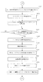
オペレータは、試刷りを開始するにあたって、試刷り枚数Pxを入力する(図8:ステップS101)。また、インキ洗浄時の回転回数N1、インキ均し時の回転回数N2、予備呼び出し動作時の回転回数N3、印刷速度Vpを入力する(ステップS103、S105、S107、S109)。
[Detailed operation of the ink supply control device]
[Input data]
When starting the trial printing, the operator inputs the number of trial printings Px (FIG. 8: Step S101). Further, the number of rotations N1 at the time of ink washing, the number of rotations N2 at the time of ink leveling, the number of rotations N3 at the time of preliminary call operation, and the printing speed Vp are input (steps S103, S105, S107, S109).
なお、この場合、試刷り枚数Pxの入力は試刷り枚数設定器37より行い、インキ洗浄時の回転回数N1の入力はインキ洗浄時の回転回数設定器38より行い、インキ均し時の回転回数N2の入力はインキ均し時の回転回数設定器39より行い、予備呼び出し動作時の回転回数N3の入力は予備呼び出し動作時の回転回数設定器40より行い、印刷速度Vpの入力は印刷速度設定器41より行う。
In this case, the trial printing number Px is inputted from the trial printing
CPU10は、試刷り枚数設定器37より入力された試刷り枚数PxをメモリM1に格納し(ステップS102)、インキ洗浄時の回転回数設定器38より入力されたインキ洗浄時の回転回数N1をメモリM2に格納し(ステップS104)、インキ均し時の回転回数設定器39より入力されたインキ均し時の回転回数N2をメモリM3に格納し(ステップS106)、予備呼び出し動作時の回転回数設定器40より入力された予備呼び出し動作時の回転回数N3をメモリM4に格納し(ステップS108)、印刷速度設定器41より入力された印刷速度VpをメモリM5に格納する(ステップS110)。
The
また、CPU10は、入力装置13より入力された刷版7のインキツボキー4−1〜4−nに対応する範囲の絵柄面積率をメモリM7に格納する。なお、この実施の形態において、刷版7のインキツボキー4−1〜4−nに対応する範囲の絵柄面積率の測定には、本出願人による特許文献3や特許文献4に示されているような「絵柄面積率測定装置」を用い、この「絵柄面積率測定装置」を用いて測定した絵柄面積率を可搬型のメモリに書き込み、この絵柄面積率が書き込まれた可搬型のメモリを入力装置13にセットすることによって、刷版7のインキツボキー4−1〜4−nに対応する範囲の絵柄面積率の入力を行う。なお、CPU10と「絵柄面積率測定装置」とをオンラインで結び、「絵柄面積率測定装置」から直接、刷版7のインキツボキー4−1〜4−nに対応する範囲の絵柄面積率を取り込むようにしてもよい。
Further, the
CPU10は、入力装置13に可搬型のメモリがセットされると、すなわちインキツボキー4−1〜4−nに対応する範囲の絵柄面積率が入力されると(図9:ステップS111のYES)、メモリM6内のカウント値NをN=1として上書きし(ステップS112)、メモリM6からカウント値Nを読み出し(ステップS113)、N番目のインキツボキーに対応する範囲の絵柄面積率を可搬型のメモリから読み出して、メモリM7のN番目のインキツボキー用のアドレス位置に記憶させる(ステップS114)。
When the portable memory is set in the
そして、メモリM6内のカウント値Nを読み出し(ステップS115)、そのカウント値Nに1を加算してメモリM6に上書きし(ステップS116)、メモリM8からインキツボキーの総数nを読み出し(ステップS117)、カウント値Nがインキツボキーの総数nを超えるまで(ステップS118のYES)、ステップS113〜S118の処理動作を繰り返す。これにより、インキツボキー4−1〜4−nに対応する刷版7の各領域毎の絵柄面積率が可搬型のメモリから読み出され、メモリM7に格納されて行く。
Then, the count value N in the memory M6 is read (step S115), 1 is added to the count value N and overwritten in the memory M6 (step S116), and the total number n of ink fountain keys is read from the memory M8 (step S117). Until the count value N exceeds the total number n of ink fountain keys (YES in step S118), the processing operations in steps S113 to S118 are repeated. As a result, the pattern area ratio for each area of the
〔インキツボキーの開き量のセット〕
次に、オペレータは、プリセット開始スイッチ16をオンとする。プリセット開始スイッチ16がオンとされると(ステップS119のYES)、CPU10は、メモリM6内のカウント値NをN=1として上書きし(図10:ステップS120)、メモリM6からカウント値Nを読み出し(ステップS121)、メモリM7のN番目のインキツボキー用のアドレス位置より、N番目のインキツボキーに対応する範囲の絵柄面積率を読み出す(ステップS122)。
[Set the opening of the ink fountain key]
Next, the operator turns on the
そして、メモリM9内の絵柄面積率−インキツボキー開き量変換テーブルを読み出し(ステップS123)、この絵柄面積率−インキツボキー開き量変換テーブルを用いて、N番目のインキツボキーに対応する範囲の絵柄面積率より、N番目のインキツボキーの開き量を求め、この求めたN番目のインキツボキーの開き量をメモリM10のN番目のインキツボキー用のアドレス位置に記憶させると共に(ステップS124)、N番目のインキツボキー制御装置300に送信する(ステップS125)。
Then, the pattern area ratio-ink fountain key opening amount conversion table in the memory M9 is read (step S123), and using this pattern area ratio-ink fountain key opening amount conversion table, the pattern area ratio in the range corresponding to the Nth ink fountain key is The opening amount of the Nth ink fountain key is obtained, and the obtained opening amount of the Nth ink fountain key is stored in the address position for the Nth ink fountain key in the memory M10 (step S124) and transmitted to the Nth ink fountain
そして、N番目のインキツボキー制御装置300からN番目のインキツボキーの開き量の受信完了信号が送信されてきたことを確認し(ステップS126のYES)、メモリM6内のカウント値Nを読み出し(ステップS127)、そのカウント値Nに1を加算してメモリM6に上書きし(ステップS128)、メモリM8からインキツボキーの総数nを読み出し(ステップS129)、カウント値Nがインキツボキーの総数nを超えるまで(ステップS130のYES)、ステップS121〜S130の処理動作を繰り返す。 Then, it is confirmed that the reception completion signal for the opening amount of the Nth ink fountain key has been transmitted from the Nth ink fountain key control device 300 (YES in step S126), and the count value N in the memory M6 is read (step S127). Then, 1 is added to the count value N and overwritten in the memory M6 (step S128), the total number n of ink fountain keys is read from the memory M8 (step S129), and the count value N exceeds the total number n of ink fountain keys (in step S130). YES), the processing operation of steps S121 to S130 is repeated.
これにより、刷版7のインキツボキー4−1〜4−nに対応する範囲の絵柄面積率に対応するインキツボキー4−1〜4−nの開き量が求められ、メモリM10に記憶されて行くと共に、インキツボキー制御装置300−1〜300−nに送信されて行く。
Thereby, the opening amount of the ink fountain keys 4-1 to 4-n corresponding to the pattern area ratio in the range corresponding to the ink fountain keys 4-1 to 4-n of the
〔インキツボキーの開き量の設定が完了していることの確認〕
そして、CPU10は、メモリM6内のカウント値NをN=1として上書きし(図11:ステップS131)、メモリM6からカウント値Nを読み出し(ステップS132)、N番目のインキツボキー制御装置300からのインキツボキーの開き量の設定完了信号の有無を確認する(ステップS133)。
[Confirmation that the ink fountain key opening amount setting is complete]
Then, the
N番目のインキツボキー制御装置300からインキツボキーの開き量の設定完了信号が送信されてきたことを確認すると(ステップS133のYES)、メモリM6内のカウント値Nを読み出し(ステップS134)、そのカウント値Nに1を加算してメモリM6に上書きし(ステップS135)、メモリM8からインキツボキーの総数nを読み出し(ステップS136)、カウント値Nがインキツボキーの総数nを超えるまで(ステップS137のYES)、ステップS132〜S137の処理動作を繰り返す。 When it is confirmed that the ink fountain key opening amount setting completion signal has been transmitted from the Nth ink fountain key control device 300 (YES in step S133), the count value N in the memory M6 is read (step S134). 1 is overwritten to the memory M6 (step S135), the total number n of ink fountain keys is read from the memory M8 (step S136), and the count value N exceeds the total number n of ink fountain keys (YES in step S137), step S132. The processing operation of S137 is repeated.
そして、カウント値Nがインキツボキーの総数nを超えると(ステップS137のYES)、CPU10は、インキツボキーの開き量の設定が完了していると判断し、全てのインキツボキー制御装置300(300−1〜300−n)に、全インキツボキーの開き量設定完了信号を送信する(ステップS138)。
When the count value N exceeds the total number n of ink fountain keys (YES in step S137), the
〔試刷り〕
次に、オペレータは、試刷り開始スイッチ17をオンとする。試刷り開始スイッチ17がオンとされると(ステップS139のYES)、CPU10は、試刷りの処理を開始する。
[Prototype]
Next, the operator turns on the trial
この試刷りの処理において、CPU10は、メモリM11に格納されているインキツボローラの回転量を読み出し(図12:ステップS140)、その読み出したインキツボローラの回転量をインキツボローラ制御装置200に送信する(ステップS141)。そして、インキツボローラ制御装置200からのインキツボローラの回転量受信完了信号を受けて(ステップS142のYES)、インキ呼び出し装置27に動作信号を出力し(ステップS143)、インキ呼び出しローラ5の呼び出し動作を開始させる。
In the trial printing process, the
また、CPU10は、メモリM5より印刷速度Vpを読み出し(ステップS144)、原動モータドライバ22にD/A変換器24を介して回転指令を出力し(ステップS145)、印刷機の速度を印刷速度Vpとする。また、給紙装置33に給紙指令を出力し(ステップS146)、印刷機への給紙を開始する。また、印刷ユニット34に印刷指令を出力するとともに(ステップS147)、インキ着ローラ着脱用エアシリンダ用バルブ36に着信号を出力し(ステップS148)、インキ着ローラ6−1〜6−4を着とし、刷版7を用いての印刷(試刷り)を開始させる。
Further, the
CPU10は、この試刷りを印刷機の回転回数がメモリM1中の試刷り枚数Pxに達するまで続ける。すなわち、CPU10は、インキ着ローラ着脱用エアシリンダ用バルブ36に着信号を出力した後(ステップS148)、印刷機の回転回数カウント用カウンタ26にリセット信号およびイネーブル信号を出力し(ステップS149)、印刷機の回転回数カウント用カウンタ26へのリセット信号の出力を停止させて(図13:ステップS150)、印刷機の回転回数カウント用カウンタ26の零からのカウント動作を開始させる。そして、印刷機の回転回数カウント用カウンタ26のカウント値を読み出してメモリM12に記憶し(ステップS151)、メモリM1中の試刷り枚数Pxを読み出し(ステップS152)、印刷機の回転回数カウント用カウンタ26のカウント値が試刷り枚数Pxに達するまで(ステップS153のYES)、ステップS151〜S153の処理動作を繰り返す。
The
そして、CPU10は、印刷機の回転回数カウント用カウンタ26のカウント値が試刷り枚数Pxに達した時点で(ステップS153のYES)、給紙装置33に給紙停止指令を出力し、給紙を停止させる(ステップS154)。また、インキ着ローラ着脱用エアシリンダ用バルブ36に脱信号を出力し(ステップS155)、インキ着ローラ6−1〜6−4を脱とする。また、印刷ユニット34に印刷停止指令を出力すると共に(ステップS156)、原動モータドライバ22に停止指令を出力し(ステップS157)、印刷機を停止させる。
Then, when the count value of the
この場合、インキローラ群6には、図7(a)に示すように、刷版7の絵柄に応じたインキ膜厚分布Mcが残される。すなわち、試刷り中のインキ膜厚分布Mcが残される。
In this case, the ink film thickness distribution Mc corresponding to the pattern of the
〔濃度測定〕
オペレータは、刷り上がった印刷物の中から1枚を抜き取り、測定台53−4(図6)上に試刷りサンプル9としてセットする。このセット状態において、試刷りサンプル9のカラーバー9−2は、測色計43のヘッド部43−1の下面に位置する。
[Concentration measurement]
The operator extracts one piece from the printed material that has been printed, and sets it as a
この状態で、オペレータは、濃度測定スイッチ18をオンとする。濃度測定スイッチ18がオンとされると(図14:ステップS158のYES)、CPU10は、濃度の測定処理を開始する。図15〜図17に濃度の測定処理のフローチャートを示す。
In this state, the operator turns on the
〔色データの採取〕
この濃度測定の処理において、CPU10は、測色計移動用モータドライバ46に正転信号を出力して、測色計移動用モータ44を正転させる(ステップS159)。この測色計移動用モータ44の正転により、ボールネジ53−3が正転し、このボールネジ53−3に案内されて測色計43が支柱53−1に接する原点位置から支柱53−2方向へ向けて移動する。
[Collecting color data]
In this density measurement process, the
CPU10は、メモリM6内のカウント値NをN=1として上書きし(ステップS160)、測色計の現在位置検出用カウンタ47のカウント値を読み出してメモリM13に記憶し(ステップS161)、この読み出したカウント値より測色計43の現在位置を演算してメモリM14に記憶し(ステップS162)、メモリM6内のカウント値Nを読み出し(ステップS163)、メモリM15中の測定すべき試刷りサンプルのN番目のパッチの位置を読み出し(ステップS164)、測色計43の現在位置がその読み出したN番目のパッチの位置に達したときに(ステップS165のYES)、測色計43に測定指令信号を出力し(ステップS166)、その位置に位置する試刷りサンプル9のパッチ9aの色データをA/D変換器48を介して測色計43により採取し、採取した色データをメモリM16のN番目のインキツボキー用のアドレス位置に記憶させる(図16:ステップS167,S168)。
The
そして、メモリM6からカウント値Nを読み出し(ステップS169)、そのカウント値Nに1を加算してメモリM6に上書きし(ステップS170)、メモリM8からインキツボキーの総数nを読み出し(ステップS171)、カウント値Nがインキツボキーの総数nを超えるまで(ステップS172のYES)、ステップS161〜S172の処理動作を繰り返す。これにより、メモリM15に記憶されているN番目のパッチの位置に達する毎に、その位置に位置する試刷りサンプル9のパッチ9aの色データが測色計43により採取され、採取した色データがメモリM16に格納されて行く。
Then, the count value N is read from the memory M6 (step S169), 1 is added to the count value N and overwritten in the memory M6 (step S170), and the total number n of ink fountain keys is read from the memory M8 (step S171). Until the value N exceeds the total number n of ink fountain keys (YES in step S172), the processing operations in steps S161 to S172 are repeated. Thus, every time the position of the Nth patch stored in the memory M15 is reached, the color data of the patch 9a of the
CPU10は、試刷りサンプル9からの色データの採取を完了すると(ステップS172のYES)、測色計移動用モータ44の正転を停止させる(ステップS173)。そして、測色計移動用モータ46を逆転させ(ステップS174)、測色計原点位置検出器49の出力がONとなって(ステップS175のYES)、測色計43が原点位置に復帰した後、測色計移動用モータの逆転を停止させる(ステップS176)。
When completing the collection of the color data from the trial printing sample 9 (YES in step S172), the
〔濃度差の算出〕
次に、CPU10は、メモリM6内のカウント値NをN=1として上書きし(図17:ステップS178)、メモリM6からカウント値Nを読み出し(ステップS179)、メモリM16のN番目のインキツボキー用のアドレス位置よりN番目のインキツボキーに対応する色データを読み出し(ステップS180)、この読み出した色データより試刷りサンプル9のN番目のインキツボキーに対応するパッチの濃度値を算出し、メモリM17のN番目のインキツボキー用のアドレス位置に記憶させる(ステップS181)。
[Calculation of density difference]
Next, the
そして、メモリM18から基準濃度値を読み出し(ステップS182)、N番目のインキツボキーに対応するパッチの濃度値より基準濃度値を減算し、これを試刷りサンプル9のN番目のインキツボキーに対応するパッチの測定濃度差としてメモリM19のN番目のインキツボキー用のアドレス位置に記憶させると共に(ステップS183)、その測定濃度を表示器14に表示する(ステップS184)。
Then, the reference density value is read from the memory M18 (step S182), the reference density value is subtracted from the density value of the patch corresponding to the Nth ink fountain key, and this is subtracted from the patch of the patch corresponding to the Nth ink fountain key of the
そして、メモリM6内のカウント値Nを読み出し(ステップS185)、そのカウント値Nに1を加算してメモリM6に上書きし(ステップS186)、メモリM8からインキツボキーの総数nを読み出し(ステップS187)、カウント値Nがインキツボキーの総数nを超えるまで(ステップS188のYES)、ステップS179〜S188の処理動作を繰り返す。これにより、試刷りサンプル9のインキツボキー4−1〜4−nに対応する各パッチの測定濃度差がメモリM19に記憶されて行く。
Then, the count value N in the memory M6 is read (step S185), 1 is added to the count value N and overwritten in the memory M6 (step S186), and the total number n of ink fountain keys is read from the memory M8 (step S187). Until the count value N exceeds the total number n of ink fountain keys (YES in step S188), the processing operations in steps S179 to S188 are repeated. As a result, the measured density difference of each patch corresponding to the ink fountain keys 4-1 to 4-n of the
なお、本実施の形態では、測色計43として分光計を使用しており、濃度計で各色のベタパッチを測定する時に用いるフィルタの各波長の透過率を分光計からの各波長の出力値に掛け、それらを合計することによって各色の濃度値を求めるようにしている。
In the present embodiment, a spectrometer is used as the
〔濃度の修正〕
次に、オペレータは、濃度修正スイッチ19をオンとする。濃度修正スイッチ19がオンとされると(図14:ステップS189のYES)、CPU10は、濃度の修正処理を開始する。図18〜図26に濃度の修正処理のフローチャートを示す。
[Density correction]
Next, the operator turns on the
〔インキツボキーの予備呼び出し時の開き量および修正した開き量(予備呼出し後の印刷時の開き量)の算出〕
CPU10は、濃度修正スイッチ19がオンとされると(ステップS189のYES)、メモリM6内のカウント値NをN=1として上書きし(図18:ステップS190)、メモリM6からカウント値Nを読み出し(ステップS191)、メモリM19から試刷りサンプル9のN番目のインキツボキーに対応するパッチの測定濃度差をΔDNとして読み出し(ステップS192)、メモリM7からN番目のインキツボキーに対応する範囲の絵柄面積率をSNとして読み出し(ステップS193)、下記(1)式を用いて、N番目のインキツボキーの予備呼び出し時の開き量θN’を算出し、メモリM20のN番目のインキツボキー用のアドレス位置に記憶させる(ステップS194)。また、下記(2)式を用いて、N番目のインキツボキーの修正した開き量(予備呼出し後の印刷時の開き量)θN”を算出し、メモリM21のN番目のインキツボキー用のアドレス位置に記憶させる(ステップS195)。
[Calculation of opening amount when ink fountain key is pre-called and corrected opening amount (opening amount when printing after pre-calling)]
When the
θN’=α・ΔDN・SN・β ・・・・(1)
θN”=SN−α・ΔDN・SN ・・・・(2)
θ N '= α · ΔD N · S N · β (1)
θ N ″ = S N −α · ΔD N · S N ... (2)
なお、上記(1)式および(2)式において、αは予め定められた補正係数である。また、上記(1)において、βはインキツローラ3の現在の回転量をインキツボローラ3の基準の回転量で除して得られる補正係数である。
In the above equations (1) and (2), α is a predetermined correction coefficient. In the above (1), β is a correction coefficient obtained by dividing the current rotation amount of the
〔インキツボキーの予備呼び出し時の開き量への設定〕
そして、CPU10は、N番目のインキツボキー制御装置300にN番目のインキツボキーの予備呼び出し時の開き量θN’を送信し(ステップS196)、N番目のインキツボキー制御装置300からのN番目のインキツボキーの開き量受信完了信号を受けて(ステップS197のYES)、メモリM6からカウント値Nを読み出し(ステップS198)、そのカウント値Nに1を加算してメモリM6に上書きし(ステップS199)、メモリM8からインキツボキーの総数nを読み出し(ステップS200)、カウント値Nがインキツボキーの総数nを超えるまで(ステップS201のYES)、ステップS191〜S201の処理動作を繰り返す。
[Set to the opening amount when the ink fountain key is pre-called]
Then, the
これにより、メモリM20にインキツボキー4−1〜4−nの予備呼び出し時の開き量θ1’〜θn’が記憶され、メモリM21にインキツボキー4−1〜4−nの修正した開き量(予備呼出し後の印刷時の開き量)θ1”〜θn”が記憶され、インキツボキー制御装置300−1〜300−nに予備呼び出し時の開き量θ1’〜θn’が送信されて行く。 As a result, the opening amounts θ1 ′ to θn ′ at the time of preliminary calling of the ink fountain keys 4-1 to 4-n are stored in the memory M20, and the corrected opening amounts of the ink fountain keys 4-1 to 4-n (after the preliminary calling) are stored in the memory M21. The opening amounts θ1 ″ to θn ″ during printing are stored, and the opening amounts θ1 ′ to θn ′ at the time of preliminary call are transmitted to the ink fountain key control devices 300-1 to 300-n.
〔インキローラ群の分割〕
次に、CPU10は、インキ呼び出し装置27に動作停止信号を出力し(図19:ステップS202)、インキ呼び出しローラ5の呼び出し動作を停止させる。そして、ローラ群分割・連結用エアシリンダ用バルブ29に分割信号を出力し(ステップS203)、インキローラ群6を上流側のローラ小群6Aと下流側のローラ小群6Bとに分割させる(図3参照)。
[Division of ink roller group]
Next, the
これにより、インキローラ群6のインキ膜厚分布Mcは、図7(b)に示すように、上流側のローラ小群6Aのインキ膜厚分布McAと下流側のローラ小群6Bのインキ膜厚分布McBとに分かれる。
Accordingly, the ink film thickness distribution Mc of the
〔上流側のローラ小群内のインキの洗浄〕
次に、CPU10は、原動モータドライバ22にD/A変換器24を介して8000rphの回転指令を出力する(ステップS204)。これにより、印刷機が回転し始め、その速度が8000rphまで上昇する。そして、CPU10は、洗浄液供給装置30に洗浄液供給指令を出力し(ステップ205)、ドクタ着脱用エアシリンダ用バルブ32に着信号を出力する(ステップS206)。これにより、洗浄液供給装置30から洗浄液が噴射され、ドクタ52がローラ6A2の周面に対接し、上流側のローラ小群6A内のインキの洗浄が開始される。
[Ink cleaning in the upstream small roller group]
Next, the
CPU10は、この上流側のローラ小群6A内のインキの洗浄を、印刷機の回転回数がメモリM2中のインキ洗浄時の回転回数N1に達するまで続ける。すなわち、CPU10は、ドクタ着脱用エアシリンダ用バルブ32に着信号を出力した後(ステップS206)、印刷機の回転回数カウント用カウンタ26にリセット信号およびイネーブル信号を出力し(ステップS207)、印刷機の回転回数カウント用カウンタ26へのリセット信号の出力を停止させて(ステップS208)、印刷機の回転回数カウント用カウンタ26の零からのカウント動作を開始させる。そして、印刷機の回転回数カウント用カウンタ26のカウント値を読み出してメモリM12に記憶し(ステップS209)、メモリM2中のインキ洗浄時の回転回数N1を読み出し(ステップS210)、印刷機の回転回数カウント用カウンタ26のカウント値がインキ洗浄時の回転回数N1に達するまで(ステップS211のYES)、ステップS209〜S211の処理動作を繰り返す。
The
そして、印刷機の回転回数カウント用カウンタ26のカウント値がインキ洗浄時の回転回数N1に達した時点で(ステップS211のYES)、洗浄液供給装置30へ洗浄液供給停止指令を出力し(図20:ステップS212)、ドクタ着脱用エアシリンダ用バルブ32に脱信号を出力し(ステップS213)、上流側のローラ小群6A内のインキの洗浄を完了させる。
Then, when the count value of the
これにより、図7(c)に示されるように、上流側のローラ小群6Aのインキ膜厚分布McAがほゞ零となる。この時、下流側のローラ小群6Bのインキ膜厚分布は、インキ洗浄時の回転回数N1により均されて、平坦なインキ膜厚分布McB’となる。
Thereby, as shown in FIG. 7C, the ink film thickness distribution McA of the
〔インキローラ群の連結〕
次に、CPU10は、ローラ群分割・連結用エアシリンダ用バルブ29に連結信号を出力し(ステップS214)、上流側のローラ小群6Aと下流側のローラ小群6Bとを連結し(図2参照)、1つのインキローラ群6に戻す(図7(d))。
[Ink roller group connection]
Next, the
そして、印刷機の回転回数カウント用カウンタ26にリセット信号およびイネーブル信号を出力し(ステップS215)、印刷機の回転回数カウント用カウンタ26へのリセット信号の出力を停止させて(ステップS216)、印刷機の回転回数カウント用カウンタ26の零からのカウント動作を開始させる。そして、印刷機の回転回数カウント用カウンタ26のカウント値を読み出してメモリM12に記憶し(ステップS217)、メモリM3中のインキ均し時の回転回数N2を読み出し(ステップS218)、印刷機の回転回数カウント用カウンタ26のカウント値がインキ均し時の回転回数N2に達するまで(ステップS219のYES)、ステップS217〜S219の処理動作を繰り返す。
Then, a reset signal and an enable signal are output to the counter for counting the number of rotations of the printing press (step S215), and the output of the reset signal to the counter for counting the number of rotations of the printing press is stopped (step S216). The
これにより、下流側のローラ小群6Bに残されているインキ膜厚分布McB’が上流側のローラ小群6Aとの間で均され、インキローラ群6に薄くて平坦なインキ膜厚分布(基本インキ膜厚分布)Md(図7(e))が形成される。
Thereby, the ink film thickness distribution McB ′ remaining in the downstream roller
〔インキローラ群の再分割〕
CPU10は、回転回数カウント用カウンタ26のカウント値がインキ均し時の回転回数N2に達すると(ステップS219のYES)、ローラ群分割・連結用エアシリンダ用バルブ29に分割信号を出力し(図21:ステップS220)、インキローラ群6を上流側のローラ小群6Aと下流側のローラ小群6Bとに再分割させる(図3参照)。これにより、インキローラ群6のインキ膜厚分布Mdは、図7(f)に示すように、上流側のローラ小群6Aの基本インキ膜厚分布MdAと下流側のローラ小群6Bの基本インキ膜厚分布MdBとに分かれる。
[Subdivision of ink roller group]
When the count value of the
〔インキツボキーの開き量の設定が完了していることの確認〕
次に、CPU10は、メモリM6内のカウント値NをN=1として上書きし(ステップS221)、メモリM6からカウント値Nを読み出し(ステップS222)、N番目のインキツボキー制御装置300からのインキツボキーの開き量の設定完了信号の有無を確認する(ステップS223)。
[Confirmation that the ink fountain key opening amount setting is complete]
Next, the
N番目のインキツボキー制御装置300からインキツボキーの開き量の設定完了信号が送信されてきたことを確認すると(ステップS223のYES)、メモリM6内のカウント値Nを読み出し(ステップS224)、そのカウント値Nに1を加算してメモリM6に上書きし(ステップS225)、メモリM8からインキツボキーの総数nを読み出し(ステップS226)、カウント値Nがインキツボキーの総数nを超えるまで(ステップS227のYES)、ステップS222〜S227の処理動作を繰り返す。 When it is confirmed that the ink fountain key opening amount setting completion signal has been transmitted from the Nth ink fountain key control device 300 (YES in step S223), the count value N in the memory M6 is read (step S224). 1 is overwritten in the memory M6 (step S225), the total number n of ink fountain keys is read from the memory M8 (step S226), and the count value N exceeds the total number n of ink fountain keys (YES in step S227), step S222. The processing operation of S227 is repeated.
そして、カウント値Nがインキツボキーの総数nを超えると(ステップS227のYES)、CPU10は、インキツボキーの開き量の設定が完了していると判断し、全てのインキツボキー制御装置300(300−1〜300−n)に、全インキツボキーの開き量設定完了信号を送信する(ステップS228)。
When the count value N exceeds the total number n of ink fountain keys (YES in step S227), the
〔予備呼び出し〕
CPU10は、全てのインキツボキー制御装置300に全インキツボキーの開き量設定完了信号を送信した後(ステップS228)、メモリM11に格納されているインキツボローラの回転量を読み出し(ステップS229)、その読み出したインキツボローラの回転量をインキツボローラ制御装置200に送信する(図22:ステップS230)。そして、インキツボローラ制御装置200からのインキツボローラの回転量受信完了信号を受けて(ステップS231のYES)、インキ呼び出し装置27に動作信号を出力し(ステップS232)、インキ呼び出しローラ5の呼び出し動作を開始させる。CPU10は、このインキ呼び出しローラ5の呼び出し動作を、印刷機の回転回数がメモリM4中の予備呼び出し動作時の回転回数N3に達するまで続ける(ステップS233〜S237)。
[Preliminary call]
The
すなわち、印刷機の回転回数カウント用カウンタ26にリセット信号およびイネーブル信号を出力し(ステップS233)、印刷機の回転回数カウント用カウンタ26へのリセット信号の出力を停止させて(ステップS234)、印刷機の回転回数カウント用カウンタ26の零からのカウント動作を開始させる。そして、印刷機の回転回数カウント用カウンタ26のカウント値を読み出してメモリM12に記憶し(ステップS235)、メモリM4中の予備呼び出し動作時の回転回数N3を読み出し(ステップS236)、印刷機の回転回数カウント用カウンタ26のカウント値が予備呼び出し動作時の回転回数N3に達するまで(ステップS237のYES)、ステップS235〜S237の処理動作を繰り返す。
That is, a reset signal and an enable signal are output to the counter for counting the number of rotations of the printing press (step S233), and the output of the reset signal to the counter for counting the number of rotations of the printing press is stopped (step S234). The
これにより、上流側のインキローラ小群6Aに予備呼び出し時のインキ膜厚分布MeAが形成される(図7(g))。
As a result, an ink film thickness distribution MeA at the time of preliminary calling is formed in the upstream ink roller
この予備呼び出しでは、上記(1)式に従って、絵柄面積率の小さいところ(インキツボキーの開き量の小さいところ)では、同じ濃度差でもインキ供給量の変化が小さくなり、絵柄面積率の大きいところ(インキツボキーの開き量の大きいところ)では、同じ濃度差でもインキ供給量の変化が大きくなる。これにより、各インキツボキーに対応する範囲の絵柄面積率の大小に拘わらず、そこへのインキの供給量を適切な値とし、予備呼出し後、すぐに正常な印刷物を印刷することが可能となる。 In this preliminary call, according to the above equation (1), when the pattern area ratio is small (where the ink fountain key opening amount is small), the change in the ink supply amount is small even with the same density difference, and the pattern area ratio is large (ink fountain key). Where the opening amount of the ink is large), the change in the ink supply amount becomes large even with the same density difference. Thus, regardless of the size of the pattern area ratio in the range corresponding to each ink fountain key, it is possible to set the ink supply amount to an appropriate value and print a normal printed matter immediately after the preliminary call.
また、この実施の形態では、上記の(1)式で示されているように、予備呼出し時のインキツボキーの開き量θN’(N=1〜n)の算出に際し、インキツボローラの回転量による補正係数βも用いている。これにより、インキツボキーの予備呼出し時の開き量θN’(N=1〜n)をさらに正確とし、より早く正常な印刷物を得ることが可能となる。 Further, in this embodiment, as shown in the above equation (1), the rotation amount of the ink fountain roller is calculated when calculating the opening amount θ N ′ (N = 1 to n) of the ink fountain key at the time of preliminary call. The correction coefficient β is also used. As a result, the opening amount θ N ′ (N = 1 to n) when the ink fountain key is preliminarily called can be made more accurate, and a normal printed matter can be obtained more quickly.
なお、この実施の形態では、予備呼出し時のインキツボキーの開き量θN’の算出に際し、インキツボローラの回転量による補正係数βを用いるようにしたが、必ずしもこの補正係数βは用いなくてもよい。 In this embodiment, the correction coefficient β based on the rotation amount of the ink fountain roller is used in calculating the ink fountain key opening amount θ N ′ at the time of the preliminary call. However, the correction coefficient β is not necessarily used. Good.
〔インキツボキーの修正した開き量(予備呼出し後の印刷時の開き量)への設定〕
CPU10は、印刷機の回転回数カウント用カウンタ26のカウント値が予備呼び出し動作時の回転回数N3に達すると(ステップS237のYES)、メモリM6内のカウント値NをN=1として上書きし(図23:ステップS238)、メモリM6からカウント値Nを読み出し(ステップS239)、メモリM21よりN番目のインキツボキーの修正した開き量θN”を読み出して(ステップS240)、N番目のインキツボキー制御装置300に送信する(ステップS241)。
[Set to the corrected opening of the ink fountain key (opening at the time of printing after preliminary call)]
When the count value of the
そして、N番目のインキツボキー制御装置300からのN番目のインキツボキーの開き量受信完了信号を受けて(ステップS242のYES)、メモリM6からカウント値Nを読み出し(ステップS243)、そのカウント値Nに1を加算してメモリM6に上書きし(ステップS244)、メモリM8からインキツボキーの総数nを読み出し(ステップS245)、カウント値Nがインキツボキーの総数nを超えるまで(ステップS246のYES)、ステップS239〜S246の処理動作を繰り返す。これにより、インキツボキー制御装置300−1〜300−nに修正した開き量θ1”〜θn”が送信されて行く。 Then, in response to the N-th ink fountain key opening amount reception completion signal from the N-th ink fountain key control device 300 (YES in step S242), the count value N is read from the memory M6 (step S243). Are added to the memory M6 (step S244), the total number n of ink fountain keys is read from the memory M8 (step S245), and the count value N exceeds the total number n of ink fountain keys (YES in step S246), steps S239 to S246. Repeat the processing operation. As a result, the corrected opening amounts θ1 ″ to θn ″ are transmitted to the ink fountain key control devices 300-1 to 300-n.
〔インキツボキーの開き量の設定が完了していることの確認〕
次に、CPU10は、メモリM6内のカウント値NをN=1として上書きし(図24:ステップS247)、メモリM6からカウント値Nを読み出し(ステップS248)、N番目のインキツボキー制御装置300からのインキツボキーの開き量の設定完了信号の有無を確認する(ステップS249)。
[Confirmation that the ink fountain key opening amount setting is complete]
Next, the
N番目のインキツボキー制御装置300からインキツボキーの開き量の設定完了信号が送信されてきたことを確認すると(ステップS249のYES)、メモリM6内のカウント値Nを読み出し(ステップS250)、そのカウント値Nに1を加算してメモリM6に上書きし(ステップS251)、メモリM8からインキツボキーの総数nを読み出し(ステップS252)、カウント値Nがインキツボキーの総数nを超えるまで(ステップS253のYES)、ステップS248〜S253の処理動作を繰り返す。 When it is confirmed that the ink fountain key opening amount setting completion signal has been transmitted from the Nth ink fountain key control device 300 (YES in step S249), the count value N in the memory M6 is read (step S250). 1 is overwritten in the memory M6 (step S251), the total number n of ink fountain keys is read from the memory M8 (step S252), and the count value N exceeds the total number n of ink fountain keys (YES in step S253), step S248. The processing operation of S253 is repeated.
そして、CPU10は、カウント値Nがインキツボキーの総数nを超えると(ステップS253のYES)、インキツボキーの開き量の設定が完了していると判断し、全てのインキツボキー制御装置300(300−1〜300−n)に、全インキツボキーの開き量設定完了信号を送信する(ステップS254)。
When the count value N exceeds the total number n of ink fountain keys (YES in step S253), the
〔インキローラ群の再連結〕
CPU10は、全てのインキツボキー制御装置300に全インキツボキーの開き量設定完了信号を送信した後(ステップS254)、ローラ群分割・連結用エアシリンダ用バルブ29に連結信号を出力し(図25:ステップS255)、上流側のローラ小群6Aと下流側のローラ小群6Bとを再連結し(図3参照)、1つのインキローラ群6に戻す(図7(h))。
[Reconnection of ink rollers]
The
〔再試刷り〕
そして、CPU10は、メモリM11に格納されているインキツボローラの回転量を読み出し(ステップS256)、その読み出したインキツボローラの回転量をインキツボローラ制御装置200に送信し(ステップS257)、インキツボローラ制御装置200からのインキツボローラの回転量受信完了信号を受けて(ステップS258のYES)、インキ呼び出し装置27に動作信号を出力し(ステップS259)、インキ呼び出しローラ5の呼び出し動作を開始させる。
[Reprint]
The
また、CPU10は、メモリM5より印刷速度Vpを読み出し(ステップS260)、原動モータドライバ22にD/A変換器24を介して回転指令を出力し(ステップS261)、印刷機の速度を印刷速度Vpとする。また、給紙装置33に給紙指令を出力し(ステップS262)、印刷機への給紙を開始する。また、印刷ユニット34に印刷指令を出力するとともに(ステップS263)、インキ着ローラ着脱用エアシリンダ用バルブ36に着信号を出力し(ステップS264)、インキ着ローラ6−1〜6−4を着とし、刷版7を用いての印刷(再試刷り)を開始させる。
Further, the
この場合、刷版7を使用しての印刷時のインキ膜厚分布(最終的な再試刷り時のインキ膜厚分布)は、印刷中(再試刷り中)に、つまり、インキローラ群6の末端からインキが消費される状態で作成される。この際、下流側のローラ小群6B内のインキ膜厚分布MdBが通常の印刷中より薄くなっているため、通常の印刷時よりも速くインキが上流側から下流側に流れ、インキローラ群6に補正されたインキ膜厚分布Mf(図7(i))が速やかに形成されるものとなる。
In this case, the ink film thickness distribution during printing using the printing plate 7 (ink film thickness distribution during final reprinting) is during printing (during reprinting), that is, at the end of the
CPU10は、この再試刷りを印刷機の回転回数がメモリM1中の試刷り枚数Pxに達するまで続ける(ステップS265〜S269)。そして、印刷機の回転回数カウント用カウンタ26のカウント値が試刷り枚数Pxに達した時点で(ステップS269のYES)、給紙装置33に給紙停止指令を出力し、給紙を停止させる(ステップS270)。また、インキ着ローラ着脱用エアシリンダ用バルブ36に脱信号を出力し(ステップS271)、インキ着ローラ6−1〜6−4を脱とする。また、印刷ユニット34に印刷停止指令を出力すると共に(ステップS272)、原動モータドライバ22に停止指令を出力し(ステップS273)、印刷機を停止させる。
The
〔本刷り〕
オペレータは、刷り上がった印刷物の濃度に問題がなければ、印刷開始スイッチ20をオンとする。なお、刷り上がった印刷物の濃度に問題があれば、上述した濃度測定(ステップS159〜S188)、濃度の修正(ステップS190〜S255)、再試刷り(S256〜S273)を繰り返す。
[Print]
If there is no problem in the density of the printed matter that has been printed, the operator turns on the
CPU10は、印刷開始スイッチ20がオンとされると(図14:ステップS274のYES)、メモリM11に格納されているインキツボローラの回転量を読み出し(ステップS275)、その読み出したインキツボローラの回転量をインキツボローラ制御装置200に送信する(ステップS276)。そして、インキツボローラ制御装置200からのインキツボローラの回転量受信完了信号を受けて(ステップS277のYES)、インキ呼び出し装置27に動作信号を出力し(ステップS278)、インキ呼び出しローラ5の呼び出し動作を開始させる。
When the
また、CPU10は、メモリM5より印刷速度Vpを読み出し(ステップS279)、原動モータドライバ22にD/A変換器24を介して回転指令を出力し(ステップS280)、印刷機の速度を印刷速度Vpとする。また、給紙装置33に給紙指令を出力し(ステップS281)、印刷機への給紙を開始する。また、印刷ユニット34に印刷指令を出力するとともに(ステップS282)、インキ着ローラ着脱用エアシリンダ用バルブ36に着信号を出力し(ステップS283)、インキ着ローラ6−1〜6−4を着とし、刷版7を用いての印刷(本刷り)を開始させる。これにより、再試刷りによって満足できる印刷物が得られた状態で、本刷りが行われる。
Further, the
〔インキツボローラ制御装置〕
図27にインキツボローラ制御装置200の内部構成の概略を示す。インキツボローラ制御装置200は、CPU201、RAM202、ROM203、インキツボローラ駆動用モータ204、インキツボローラ駆動用モータドライバ205、インキツボローラ駆動用モータ用ロータリーエンコーダ206、入出力インターフェイス(I/O,I/F)207,208、メモリ209,210を備えており、インターフェイス207を介してインキ供給量制御装置100と接続されている。メモリ209には受信したインキツボローラの回転量が記憶される。メモリ210には目標とするインキツボローラの送り量が記憶される。
[Ink fountain roller control device]
FIG. 27 shows an outline of the internal configuration of the ink fountain
CPU201は、インキ供給量制御装置100よりインキツボローラの回転量が送られてくると(図28:ステップS301のYES)、その受信した回転量をメモリ209に記憶する(ステップS302)。また、インキ供給量制御装置100に、インキツボローラの回転量受信完了信号を送信する(ステップS303)。また、受信したインキツボローラの回転量を目標とするインキツボローラの送り量(目標回転量)としてメモリ210に記憶する(ステップS304)。そして、メモリ210から目標回転量を読み出し(ステップS305)、インキツボローラ駆動用モータドライバ205へ送り、インキツボローラ駆動用モータ204の回転量を目標回転量に合わせ込む(ステップS306)。
When the rotation amount of the ink fountain roller is sent from the ink supply amount control device 100 (FIG. 28: YES in step S301), the
〔インキツボキー制御装置〕
図29にインキツボキー制御装置300(300−1〜300−n)の内部構成の概略を示す。インキツボキー制御装置300は、CPU301、RAM302、ROM303、インキツボキー駆動用モータ304、インキツボキー駆動用モータドライバ305、インキツボキー駆動用モータ用ロータリーエンコーダ306、カウンタ307、入出力インターフェイス(I/O,I/F)308,309、メモリ310〜313を備えており、インターフェイス308を介してインキ供給量制御装置100と接続されている。メモリ310には受信したインキツボキーの開き量が記憶される。メモリ311には目標とするインキツボキーの開き量が記憶される。メモリ312にはカウンタ307のカウント値が記憶される。メモリ313には現在のインキツボキーの開き量が記憶される。
[Ink fountain key control device]
FIG. 29 shows an outline of the internal configuration of the ink fountain key control device 300 (300-1 to 300-n). The ink fountain
CPU301は、インキ供給量制御装置100よりインキツボキーの開き量が送られてくると(図30:ステップS401のYES)、その受信した開き量をメモリ310に記憶するとともに(ステップS402)、インキ供給量制御装置100にインキツボキーの開き量受信完了信号を送信する(ステップS403)。また、受信したインキツボキーの開き量を目標とする開き量としてメモリ311に記憶する(ステップS404)。
When the ink fountain key opening amount is sent from the ink supply amount control device 100 (FIG. 30: YES in step S401), the
そして、カウンタ307のカウント値を読み取ってメモリ312に記憶し(ステップS405)、この読み取ったカウンタ307のカウント値より現在のインキツボキーの開き量を求めてメモリ313に記憶し(ステップS406)、メモリ311から目標とするインキツボキーの開き量を読み出し(ステップS407)、現在のインキツボキーの開き量が目標とする開き量と同じであれば(ステップS408のYES)、直ちにステップS417(図31)へ進み、インキ供給量制御装置100へインキツボキーの開き量の設定完了信号を出力する。
The count value of the
現在のインキツボキーの開き量が目標とする開き量と同じでない場合には(ステップS408のNO)、現在のインキツボキーの開き量が目標とする開き量と同じになるまでインキツボキー駆動用モータ304を駆動した後(図31:ステップS409〜S416)、インキ供給量制御装置100へインキツボキーの開き量の設定完了信号を出力する(ステップS417)。
If the current ink fountain key opening amount is not the same as the target opening amount (NO in step S408), the ink fountain
すなわち、現在のインキツボキーの開き量が目標とする開き量よりも小さい場合には(ステップS409のYES)、インキツボキー駆動用モータドライバ305に正転指令を送り(ステップS410)、カウンタ307よりカウント値を読み出して(ステップS412)、そのカウント値より現在のインキツボキーの開き量を演算し(ステップS413)、メモリ311から目標とするインキツボキーの開き量を読み出し(ステップS414)、現在のインキツボキーの開き量が目標とするインキツボキーの開き量と一致するまで(ステップS415のYES)、ステップS412〜S415の処理動作を繰り返す。
That is, if the current ink fountain key opening amount is smaller than the target opening amount (YES in step S409), a forward rotation command is sent to the ink fountain key driving motor driver 305 (step S410), and the count value is obtained from the
また、現在のインキツボキーの開き量が目標とする開き量よりも大きい場合には(ステップS409のNO)、インキツボキー駆動用モータドライバ305に逆転指令を送り(ステップS411)、カウンタ307よりカウント値を読み出して(ステップS412)、そのカウント値より現在のインキツボキーの開き量を演算し(ステップS413)、メモリ311から目標とするインキツボキーの開き量を読み出し(ステップS414)、現在のインキツボキーの開き量が目標とするインキツボキーの開き量と一致するまで(ステップS415のYES)、ステップS412〜S415の処理動作を繰り返す。
If the current ink fountain key opening amount is larger than the target opening amount (NO in step S409), a reverse rotation command is sent to the ink fountain key driving motor driver 305 (step S411), and the count value is read from the
そして、ステップS415において現在のインキツボキーの開き量が目標とするインキツボキーの開き量と一致すれば(ステップS415のYES)、インキツボキー駆動用モータドライバ305に停止指令を出力し(ステップS416)、インキ供給量制御装置100へインキツボキーの開き量の設定完了信号を出力する(ステップS417)。 If the current ink fountain key opening amount matches the target ink fountain key opening amount in step S415 (YES in step S415), a stop command is output to the ink fountain key driving motor driver 305 (step S416), and the ink supply amount A setting completion signal for the ink fountain key opening amount is output to the control device 100 (step S417).
インキ供給量制御装置100へインキツボキーの開き量の設定完了信号を出力すると(ステップS417)、CPU301は、インキ供給量制御装置100からの全インキツボキーの開き量設定完了信号を受信した時点で(ステップS418のYES)、インキ供給量制御装置100へのインキツボキーの開き量の設定完了信号の出力を停止する(ステップS419)。
When the ink fountain key opening amount setting completion signal is output to the ink supply amount control device 100 (step S417), the
なお、上述した実施の形態では、ステップS194(図18)において、前記(1)式で示したように、各インキツボキーの予備呼出し時の開き量θN’の算出に際して各インキツボキーに対応する範囲の絵柄面積率SNを用いるようにしたが、各インキツボキーに対応する範囲の絵柄面積率SNに代えて、各インキツボキーに対応する範囲の絵柄面積を用いるようにしてもよく、各インキツボキーの現在の開き量を用いるようにしてもよい。 In the above-described embodiment, in step S194 (FIG. 18), as shown by the equation (1), when the opening amount θ N ′ for each ink fountain key is calculated, the range corresponding to each ink fountain key is calculated. Although the pattern area ratio S N is used, the pattern area ratio SN corresponding to each ink fountain key may be used instead of the pattern area ratio S N corresponding to each ink fountain key. The opening amount may be used.
また、ステップS196(図18)において、前記(2)式で示しように、各インキツボキーの修正した開き量(予備呼出し後の印刷時の開き量)θN”の算出に際して各インキツボキーに対応する範囲の絵柄面積率SNを用いるようにしたが、各インキツボキーに対応する範囲の絵柄面積率SNに代えて、各インキツボキーに対応する範囲の絵柄面積を用いるようにしてもよく、各インキツボキーの現在の開き量を用いるようにしてもよい。 In step S196 (FIG. 18), as indicated by the above equation (2), the range corresponding to each ink fountain key when calculating the corrected opening amount of each ink fountain key (opening amount at the time of printing after preliminary call) θ N ″ image area rate has been to use a S N, in place of the image area ratio S N of a range corresponding to each ink fountain key, may be used, the image area of the range corresponding to each ink fountain key, the current of each ink fountain key You may make it use the opening amount of.
例えば、各インキツボキーの現在の開き量を用いる場合には、インキツボキーの現在の開き量をθNとし、下記(3)式を用いて、各インキツボキーの予備呼出し時の開き量θN’を求めるようにし、下記(4)式を用いて、各インキツボキーの修正した開き量(予備呼出し後の印刷時の開き量)θN”を求めるようにする。 For example, when the current opening amount of each ink fountain key is used, the current opening amount of the ink fountain key is set as θ N, and the opening amount θ N ′ at the time of preliminary calling of each ink fountain key is obtained using the following equation (3). Then, the corrected opening amount of each ink fountain key (opening amount at the time of printing after preliminary call) θ N ″ is obtained using the following equation (4).
θN’=α・ΔDN・θN・β ・・・・(3)
θN”=θN−α・ΔDN・θN ・・・・(4)
θ N '= α · ΔD N · θ N · β (3)
θ N ″ = θ N −α · ΔD N · θ N ... (4)
また、上述した実施の形態では、上流側のローラ小群6Aに対して洗浄液供給装置27とドクタ41とによって構成されるインキ洗浄装置を設けるようにしたが、ブレードで掻き取るなどして、上流側のローラ小群6A内のインキを除去するようにしてもよい。
Further, in the above-described embodiment, the ink cleaning device constituted by the cleaning
また、上述した実施の形態では、インキローラ群6を上流側のローラ小群6Aと下流側のローラ小群6Bとに2分割するようにしたが、3分割したり、4分割したりするなど、さらに多くのローラ小群に分割するようにしてもよい。また、その場合、分割されたローラ小群のうちの一部のローラ小群内のインキを除去するようにするが、一部のローラ小群であればその数は複数であってもよい。
In the above-described embodiment, the
また、上述した実施の形態では、揺動アーム51を用いてインキローラ群6を分割・連結するようにしたが、インキローラ群6を分割・連結する機構は揺動アームを用いた機構に限られるものでないことは言うまでもない。
In the above-described embodiment, the
また、上述した実施の形態では、試刷り中にインキローラ群6のインキ膜厚分布を補正する場合について説明したが、本刷り中であっても同様にして、インキローラ群6のインキ膜厚分布を補正することが可能である。
In the above-described embodiment, the case where the ink film thickness distribution of the
本発明のインキ膜厚分布の補正方法および装置は、試刷り中又は本刷り中に、インキ供給装置におけるインキローラ群のインキ膜厚分布を補正するインキ膜厚部分の補正方法および装置として、輪転印刷機など各種の印刷機に適用することが可能である。 The ink film thickness distribution correction method and apparatus according to the present invention is a rotary film rotation portion correction method and apparatus that corrects the ink film thickness distribution of the ink roller group in the ink supply apparatus during trial printing or actual printing. The present invention can be applied to various printing machines such as a printing machine.
1…インキツボ、2…インキ、3…インキツボローラ、4(4−1〜4−n)…インキツボキー、5…インキ呼び出しローラ、6…インキローラ群、6−1〜6−4…インキ着ローラ、6A…上流側のローラ小群、6B…下流側のローラ小群、6A1,6A2,6B1…ローラ、7…刷版、8…版胴、10…CPU、11…RAM、12…ROM、13…入力装置、14…表示器、15…出力装置(プリンタ等)、16…プリセット開始スイッチ、17…試刷り開始スイッチ、18…濃度測定スイッチ、19…濃度修正スイッチ、20…印刷開始スイッチ、21…印刷機の原動モータ、22…原動モータドライバ、23…原動モータ用ロータリーエンコーダ、24…D/A変換器、25…印刷機の原点位置検出器、26…印刷機の回転回数カウント用カウンタ、27…インキ呼び出し装置、28…ローラ群分割・連結用エアシリンダ、29…ローラ群分割・連結用エアシリンダ用バルブ、30…洗浄液供給装置、31…ドクタ着脱用エアシリンダ、32…ドクタ着脱用エアシリンダ用バルブ、33…給紙装置、34…印刷ユニット、35…インキ着ローラ着脱用エアシリンダ、36…インキ着ローラ着脱用エアシリンダ用バルブ、37…試刷り枚数設定器、38…インキ洗浄時の回転回数設定器、39…インキ均し時の回転回数設定器、40…予備呼び出し動作時の回転回数設定器、41…印刷速度設定器、42…メモリ、43…測色計、44…測色計移動用モータ、45…測色計移動用モータ用ロータリーエンコーダ、46…測色計移動用モータドライバ、47…測色計の現在位置検出用カウンタ、48…A/D変換器、49…測色計原点位置検出器、50−1〜50−14…入出力インターフェイス(I/O,I/F)、51…揺動アーム、52…ドクタ、M1〜M21…メモリ、100…インキ供給量制御装置、200…インキツボローラ制御装置、201…CPU、202…RAM、203…ROM、204…インキツボローラ駆動用モータ、205…インキツボローラ駆動用モータドライバ、206…インキツボローラ駆動用モータ用ロータリーエンコーダ、207,208…入出力インターフェイス(I/O,I/F)、209,210…メモリ、300(300−1〜300−n)…インキツボキー制御装置、301…CPU、302…RAM、303…ROM、304…インキツボキー駆動用モータ、305…インキツボキー駆動用モータドライバ、306…インキツボキー駆動用モータ用ロータリーエンコーダ、307…カウンタ、308,309…入出力インターフェイス(I/O,I/F)、310〜313…メモリ。
DESCRIPTION OF
Claims (8)
試刷り中又は本刷り中に、前記インキローラ群のインキの流動経路の末端に位置するインキ着ローラを脱とするとともに、前記インキ呼び出しローラの呼び出し動作を停止し、前記インキローラ群を複数のローラ小群に分割するローラ群分割ステップと、
前記ローラ群分割ステップによって分割された複数のローラ小群のうちの一部のローラ小群内のインキを除去するインキ除去ステップと
を備えることを特徴とするインキ膜厚分布の補正方法。 A plurality of ink fountain keys are provided, and the amount of ink supplied to the ink fountain roller from within the ink fountain is adjusted by adjusting the opening amount of these ink fountain keys. In the ink film thickness distribution correction method for correcting the ink film thickness distribution of the ink roller group in the ink supply device to be supplied to the printing plate via a trial printing or the actual printing,
During the trial printing or the main printing, the ink adhering roller located at the end of the ink flow path of the ink roller group is removed, and the calling operation of the ink calling roller is stopped, and the ink roller group is divided into a plurality of ink roller groups. A roller group dividing step for dividing the roller into small groups;
An ink film thickness distribution correcting method comprising: an ink removing step of removing ink in a part of the plurality of roller subgroups divided by the roller group dividing step.
前記インキ除去ステップによって前記一部のローラ小群内のインキが除去された後、前記分割されている複数のローラ小群を連結して1つのインキローラ群に戻すローラ群連結ステップと、
前記ローラ群連結ステップによって1つに戻された前記インキローラ群を任意の回転回数駆動させるインキローラ群駆動ステップと
を備えることを特徴とするインキ膜厚分布の補正方法。 In the ink film thickness distribution correction method according to claim 1,
A roller group connecting step of connecting the plurality of divided roller small groups and returning them to one ink roller group after ink in the partial roller small groups is removed by the ink removing step;
An ink film thickness distribution correction method comprising: an ink roller group driving step of driving the ink roller group returned to one by the roller group connecting step an arbitrary number of rotations.
印刷機により印刷された印刷用紙の前記各インキツボキーに対応する範囲に印刷された各濃度測定用のパッチの濃度値を測定する濃度値測定ステップと、
前記測定された各濃度測定用のパッチの濃度値と予め設定されている基準濃度値との差および前記各インキツボキーに対応する範囲の前記刷版の絵柄面積率に基づいて前記各インキツボキーの予備呼び出し時の開き量を求める予備呼出時開量演算ステップと、
前記各インキツボキーの開き量を前記予備呼び出し時の開き量に設定する予備呼出時開量設定ステップと、
前記インキローラ群駆動ステップによって前記インキローラ群が任意の回転回数駆動された後、当該インキローラ群を複数のローラ小群に再分割するローラ群再分割ステップと、
前記ローラ群再分割ステップによって前記インキローラ群が複数のローラ小群に再分割された状態で、かつ前記予備呼出時開量設定ステップによって前記各インキツボキーの開き量が前記予備呼び出し時の開き量に設定された状態で、前記インキ呼び出しローラの呼び出し動作を所定回数行い、前記再分割された複数のローラ小群の上流側のローラ小群に予備呼び出し時のインキ膜厚分布を形成する予備呼出ステップと
を備えることを特徴とするインキ膜厚分布の補正方法。 In the correction method of the ink film thickness distribution according to claim 2,
A density value measuring step for measuring a density value of each density measurement patch printed in a range corresponding to each ink fountain key of the printing paper printed by a printing machine ;
Preliminary call of each ink fountain key based on the difference between the measured density value of each density measurement patch and a preset reference density value and the pattern area ratio of the printing plate in the range corresponding to each ink fountain key Opening amount calculation step at the time of preliminary call to obtain the opening amount of time,
Preliminary call opening amount setting step for setting the opening amount of each ink fountain key to the opening amount at the time of preliminary calling;
A roller group re-dividing step for re-dividing the ink roller group into a plurality of roller sub-groups after the ink roller group is driven an arbitrary number of rotations by the ink roller group driving step;
The ink roller group is subdivided into a plurality of roller subgroups by the roller group subdivision step, and the opening amount of each ink fountain key is changed to the opening amount at the preliminary calling by the preliminary call opening amount setting step. A pre-calling step of performing the ink-calling roller calling operation a predetermined number of times in a set state, and forming an ink film thickness distribution at the time of pre-calling in the roller sub-group upstream of the plurality of sub-groups of the subdivided rollers A method for correcting an ink film thickness distribution, comprising:
前記測定された各濃度測定用のパッチの濃度値と予め設定されている基準濃度値との差および前記各インキツボキーに対応する範囲の前記刷版の絵柄面積率に基づいて前記各インキツボキーの予備呼び出し後の印刷時の開き量を求める印刷時開量演算ステップと、
前記各インキツボキーの開き量を前記予備呼び出し後の印刷時の開き量に設定する印刷時開量設定ステップと、
前記予備呼出ステップによって前記上流側のローラ小群に前記予備呼び出し時のインキ膜厚分布が形成された後、前記再分割された複数のローラ小群を再連結して1つのインキローラ群に戻すローラ群再連結ステップと、
前記ローラ群再連結ステップによって前記再分割されたローラ小群が1つのインキローラ群に戻された状態で、かつ前記印刷時開量設定ステップによって前記各インキツボキーの開き量が前記予備呼び出し後の印刷時の開き量に設定された状態で、前記インキ着ローラを着とし、前記刷版を使用しての印刷を再開する印刷再開ステップと
を備えることを特徴とするインキ膜厚分布の補正方法。 In the correction method of the ink film thickness distribution according to claim 3,
Preliminary call of each ink fountain key based on the difference between the measured density value of each density measurement patch and a preset reference density value and the pattern area ratio of the printing plate in the range corresponding to each ink fountain key A step of calculating the opening amount during printing to obtain the opening amount during subsequent printing;
An opening amount setting step during printing for setting the opening amount of each ink fountain key to the opening amount during printing after the preliminary call;
After the preliminary call step, the ink film thickness distribution at the time of the preliminary call is formed on the upstream roller small group, and then the plurality of subdivided roller small groups are reconnected and returned to one ink roller group. A roller group reconnection step;
In the state where the sub-group of rollers subdivided by the roller group reconnecting step is returned to one ink roller group, the opening amount of each ink fountain key is printed after the preliminary call by the opening amount setting step at the time of printing. And a printing resumption step of resuming printing using the printing plate with the ink application roller set in a state where the opening amount is set to a time opening amount.
前記インキローラ群のインキの流動経路の末端に位置するインキ着ローラを脱とするとともに、前記インキ呼び出しローラの呼び出し動作を停止させ、前記インキローラ群を複数のローラ小群に分割するローラ群分割手段と、
試刷り中又は本刷り中に、前記ローラ群分割手段が行う前記インキ着ローラを脱とするタイミング、前記インキ呼び出しローラの呼び出し動作を停止するタイミング、前記インキローラ群を複数のローラ小群に分割するタイミングを制御する制御手段と、
前記ローラ群分割手段によって分割された複数のローラ小群のうちの一部のローラ小群内のインキを除去するインキ除去手段と
を備えることを特徴とするインキ膜厚分布の補正装置。 A plurality of ink fountain keys are provided, and the amount of ink supplied to the ink fountain roller from within the ink fountain is adjusted by adjusting the opening amount of these ink fountain keys. In the ink film thickness distribution correction device that corrects the ink film thickness distribution in the ink roller group in the ink supply device to be supplied to the printing plate through the trial printing or the actual printing ,
With the ink form rollers located at the end of the flow path of the ink before Symbol ink roller group to detach, the call operation of said ink ductor roller is stopped, the roller group for dividing the ink roller group into a plurality of roller subgroup Dividing means;
During the trial printing or the actual printing, the timing at which the roller for dividing the ink application roller is removed, the timing at which the calling operation of the ink calling roller is stopped, and the ink roller group is divided into a plurality of small roller groups. Control means for controlling the timing to perform;
An ink film thickness distribution correction apparatus comprising: an ink removing unit that removes ink in a part of the plurality of roller subgroups divided by the roller group dividing unit.
前記インキ除去手段によって前記一部のローラ小群内のインキが除去された後、前記分割されている複数のローラ小群を連結して1つのインキローラ群に戻すローラ群連結手段と、
前記ローラ群連結手段によって1つに戻された前記インキローラ群を任意の回転回数駆動させるインキローラ群駆動手段と
を備えることを特徴とするインキ膜厚分布の補正装置。 In the ink film thickness distribution correction apparatus according to claim 5,
A roller group connecting means for connecting the plurality of divided roller small groups and returning them to one ink roller group after the ink in the partial roller small groups is removed by the ink removing means;
An ink film thickness distribution correcting device comprising: an ink roller group driving unit that drives the ink roller group returned to one by the roller group coupling unit an arbitrary number of rotations.
印刷機により印刷された印刷用紙の前記各インキツボキーに対応する範囲に印刷された各濃度測定用のパッチの濃度値を測定する濃度値測定手段と、
前記測定された各濃度測定用のパッチの濃度値と予め設定されている基準濃度値との差および前記各インキツボキーに対応する範囲の前記刷版の絵柄面積率に基づいて前記各インキツボキーの予備呼び出し時の開き量を求める予備呼出時開量演算手段と、
前記各インキツボキーの開き量を前記予備呼び出し時の開き量に設定する予備呼出時開量設定手段と、
前記インキローラ群駆動手段によって前記インキローラ群が任意の回転回数駆動された後、当該インキローラ群を複数のローラ小群に再分割するローラ群再分割手段と、
前記ローラ群再分割手段によって前記インキローラ群が複数のローラ小群に再分割された状態で、かつ前記予備呼出時開量設定手段によって前記各インキツボキーの開き量が前記予備呼び出し時の開き量に設定された状態で、前記インキ呼び出しローラの呼び出し動作を所定回数行い、前記再分割された複数のローラ小群の上流側のローラ小群に予備呼び出し時のインキ膜厚分布を形成する予備呼出手段と
を備えることを特徴とするインキ膜厚分布の補正装置。 In the ink film thickness distribution correcting apparatus according to claim 6,
Density value measuring means for measuring the density value of each density measurement patch printed in a range corresponding to each ink fountain key of the printing paper printed by a printing machine ;
Preliminary call of each ink fountain key based on the difference between the measured density value of each density measurement patch and a preset reference density value and the pattern area ratio of the printing plate in the range corresponding to each ink fountain key A preliminary call opening amount calculation means for obtaining an opening amount of time,
Preliminary call opening amount setting means for setting the opening amount of each ink fountain key to the opening amount at the time of preliminary calling;
Roller group re-dividing means for re-dividing the ink roller group into a plurality of roller sub-groups after the ink roller group is driven by the ink roller group driving means at an arbitrary number of rotations;
The ink roller group is subdivided into a plurality of roller subgroups by the roller group subdividing means, and the opening amount of each ink fountain key is changed to the opening amount at the time of preliminary calling by the preliminary call opening amount setting means. Preliminary calling means for performing the calling operation of the ink calling roller a predetermined number of times in a set state, and forming an ink film thickness distribution at the time of preliminary calling in the roller subgroup upstream of the plurality of subdivided roller subgroups An apparatus for correcting an ink film thickness distribution, comprising:
前記測定された各濃度測定用のパッチの濃度値と予め設定されている基準濃度値との差および前記各インキツボキーに対応する範囲の前記刷版の絵柄面積率に基づいて前記各インキツボキーの予備呼び出し後の印刷時の開き量を求める印刷時開量演算手段と、
前記各インキツボキーの開き量を前記予備呼び出し後の印刷時の開き量に設定する印刷時開量設定手段と、
前記予備呼出手段によって前記上流側のローラ小群に前記予備呼び出し時のインキ膜厚分布が形成された後、前記再分割された複数のローラ小群を再連結して1つのインキローラ群に戻すローラ群再連結手段と、
前記ローラ群再連結手段によって前記再分割されたローラ小群が1つのインキローラ群に戻された状態で、かつ前記印刷時開量設定手段によって前記各インキツボキーの開き量が前記予備呼び出し後の印刷時の開き量に設定された状態で、前記インキ着ローラを着とし、前記刷版を使用しての印刷を再開する印刷再開手段と
を備えることを特徴とするインキ膜厚分布の補正装置。 In the ink film thickness distribution correcting apparatus according to claim 7,
Preliminary call of each ink fountain key based on the difference between the measured density value of each density measurement patch and a preset reference density value and the pattern area ratio of the printing plate in the range corresponding to each ink fountain key An opening amount calculation means for calculating an opening amount at the time of subsequent printing;
An opening amount setting means at the time of printing for setting the opening amount of each ink fountain key to the opening amount at the time of printing after the preliminary call;
After the ink film thickness distribution at the time of preliminary calling is formed on the upstream roller small group by the preliminary calling means, the plurality of subdivided roller small groups are reconnected and returned to one ink roller group. Roller group reconnection means;
In the state where the sub-group of rollers subdivided by the roller group reconnecting means is returned to one ink roller group, the opening amount of each ink fountain key is printed after the preliminary call by the opening amount setting means during printing. An ink film thickness distribution correcting apparatus comprising: a printing restarting unit configured to wear the ink applying roller and restart printing using the printing plate in a state in which the opening amount is set.
Priority Applications (4)
| Application Number | Priority Date | Filing Date | Title |
|---|---|---|---|
| JP2011198381A JP5897852B2 (en) | 2011-09-12 | 2011-09-12 | Method and apparatus for correcting ink film thickness distribution |
| EP12181521.1A EP2567817B1 (en) | 2011-09-12 | 2012-08-23 | Ink film thickness distribution correction method and apparatus |
| US13/600,169 US8919251B2 (en) | 2011-09-12 | 2012-08-30 | Ink film thickness distribution correction method and apparatus |
| CN201210337104.2A CN102991120B (en) | 2011-09-12 | 2012-09-12 | Ink film thickness distribution correction method and apparatus |
Applications Claiming Priority (1)
| Application Number | Priority Date | Filing Date | Title |
|---|---|---|---|
| JP2011198381A JP5897852B2 (en) | 2011-09-12 | 2011-09-12 | Method and apparatus for correcting ink film thickness distribution |
Publications (3)
| Publication Number | Publication Date |
|---|---|
| JP2013059878A JP2013059878A (en) | 2013-04-04 |
| JP2013059878A5 JP2013059878A5 (en) | 2014-10-16 |
| JP5897852B2 true JP5897852B2 (en) | 2016-04-06 |
Family
ID=47221091
Family Applications (1)
| Application Number | Title | Priority Date | Filing Date |
|---|---|---|---|
| JP2011198381A Active JP5897852B2 (en) | 2011-09-12 | 2011-09-12 | Method and apparatus for correcting ink film thickness distribution |
Country Status (4)
| Country | Link |
|---|---|
| US (1) | US8919251B2 (en) |
| EP (1) | EP2567817B1 (en) |
| JP (1) | JP5897852B2 (en) |
| CN (1) | CN102991120B (en) |
Cited By (1)
| Publication number | Priority date | Publication date | Assignee | Title |
|---|---|---|---|---|
| JP2014094525A (en) * | 2012-11-12 | 2014-05-22 | Komori Corp | Correction method of ink film thickness distribution and device of the same |
Families Citing this family (7)
| Publication number | Priority date | Publication date | Assignee | Title |
|---|---|---|---|---|
| JP5897853B2 (en) * | 2011-09-12 | 2016-04-06 | 株式会社小森コーポレーション | Method and apparatus for forming ink film thickness distribution |
| JP6114503B2 (en) | 2012-04-26 | 2017-04-12 | 株式会社小森コーポレーション | Ink supply method and ink supply apparatus |
| JP6093152B2 (en) | 2012-11-12 | 2017-03-08 | 株式会社小森コーポレーション | Ink supply method and ink supply apparatus |
| JP6335488B2 (en) * | 2013-11-22 | 2018-05-30 | 株式会社小森コーポレーション | Ink supply method and ink supply apparatus |
| WO2015076364A1 (en) * | 2013-11-22 | 2015-05-28 | 株式会社小森コーポレーション | Ink supply method and ink supply device |
| JP6240481B2 (en) * | 2013-11-22 | 2017-11-29 | 株式会社小森コーポレーション | Ink supply method and ink supply apparatus |
| CN113601992A (en) * | 2021-07-23 | 2021-11-05 | 漳州市三和兴业包装纸品有限公司 | Digital printing grouping coloring and ink saving printing method |
Family Cites Families (19)
| Publication number | Priority date | Publication date | Assignee | Title |
|---|---|---|---|---|
| US3701316A (en) * | 1970-05-18 | 1972-10-31 | Harris Intertype Corp | Ink and dampener form roll interruption for cleaning purposes |
| JPS5851154A (en) * | 1981-09-22 | 1983-03-25 | Mitsubishi Heavy Ind Ltd | Ink supply device |
| JPS58201010A (en) | 1982-05-19 | 1983-11-22 | Komori Printing Mach Co Ltd | Method for calibrating pattern signal |
| JPS58201008A (en) | 1982-05-19 | 1983-11-22 | Komori Printing Mach Co Ltd | Device for measuring area of pattern of printing board |
| DE3338143C2 (en) * | 1983-10-20 | 1986-12-18 | M.A.N.- Roland Druckmaschinen AG, 6050 Offenbach | Process for generating an ink layer thickness corresponding to the printed image in the inking unit of a printing machine |
| DE3629081C1 (en) * | 1986-08-27 | 1988-03-24 | Roland Man Druckmasch | Convertible inking unit of a sheet-fed rotary printing press |
| DE9212582U1 (en) * | 1992-09-18 | 1992-11-26 | Heidelberger Druckmaschinen Ag, 6900 Heidelberg | Device for washing an inking unit on printing machines |
| JPH1016193A (en) | 1996-06-27 | 1998-01-20 | Komori Corp | Method of controlling ink film thickness |
| DE19708435C2 (en) * | 1997-03-01 | 2001-05-10 | Heidelberger Druckmasch Ag | Process for cleaning an inking unit of a printing press |
| JPH11188844A (en) | 1997-12-26 | 1999-07-13 | Komori Corp | Method and device for controlling ink film thickness in printer |
| JPH11348238A (en) * | 1998-06-04 | 1999-12-21 | Mitsubishi Heavy Ind Ltd | Ink supply device |
| JP4197379B2 (en) | 1999-09-07 | 2008-12-17 | 株式会社小森コーポレーション | Ink supply amount adjustment method and apparatus for multicolor printing machine |
| JP2001322250A (en) * | 2000-05-17 | 2001-11-20 | Komori Corp | Printer and method for controlling printer |
| DE10209861B4 (en) * | 2002-03-06 | 2012-10-04 | manroland sheetfed GmbH | Method and apparatus for ink supply control |
| JP4040968B2 (en) | 2002-12-26 | 2008-01-30 | 株式会社小森コーポレーション | Ink supply amount control method and apparatus for printing press |
| JP2006137096A (en) | 2004-11-12 | 2006-06-01 | Komori Corp | Method and equipment for regulating ink supply of printing press |
| JP2007030348A (en) * | 2005-07-27 | 2007-02-08 | Komori Corp | Method/device for adjusting ink supply to printing machine |
| JP5513808B2 (en) | 2009-08-10 | 2014-06-04 | 株式会社小森コーポレーション | Method and apparatus for adjusting ink supply amount of printing press |
| JP5897853B2 (en) * | 2011-09-12 | 2016-04-06 | 株式会社小森コーポレーション | Method and apparatus for forming ink film thickness distribution |
-
2011
- 2011-09-12 JP JP2011198381A patent/JP5897852B2/en active Active
-
2012
- 2012-08-23 EP EP12181521.1A patent/EP2567817B1/en active Active
- 2012-08-30 US US13/600,169 patent/US8919251B2/en active Active
- 2012-09-12 CN CN201210337104.2A patent/CN102991120B/en active Active
Cited By (1)
| Publication number | Priority date | Publication date | Assignee | Title |
|---|---|---|---|---|
| JP2014094525A (en) * | 2012-11-12 | 2014-05-22 | Komori Corp | Correction method of ink film thickness distribution and device of the same |
Also Published As
| Publication number | Publication date |
|---|---|
| US20130061768A1 (en) | 2013-03-14 |
| EP2567817A2 (en) | 2013-03-13 |
| CN102991120B (en) | 2014-12-31 |
| US8919251B2 (en) | 2014-12-30 |
| EP2567817A3 (en) | 2014-11-26 |
| JP2013059878A (en) | 2013-04-04 |
| EP2567817B1 (en) | 2017-05-10 |
| CN102991120A (en) | 2013-03-27 |
Similar Documents
| Publication | Publication Date | Title |
|---|---|---|
| JP5897852B2 (en) | Method and apparatus for correcting ink film thickness distribution | |
| JP6220117B2 (en) | Control device and control method for printing press | |
| JP5897853B2 (en) | Method and apparatus for forming ink film thickness distribution | |
| EP1747885A2 (en) | Ink supply amount adjustment method and apparatus for printing press | |
| JP6093151B2 (en) | Method and apparatus for correcting ink film thickness distribution | |
| JP6114503B2 (en) | Ink supply method and ink supply apparatus | |
| JP6093152B2 (en) | Ink supply method and ink supply apparatus | |
| CN100393512C (en) | Ink supply amount adjustment method and apparatus for printing press | |
| JP6335488B2 (en) | Ink supply method and ink supply apparatus | |
| JP6240481B2 (en) | Ink supply method and ink supply apparatus | |
| EP1950037A2 (en) | Switch-Over Processing Method And apparatus | |
| JP6148128B2 (en) | Ink supply amount adjusting apparatus and method | |
| JP6174467B2 (en) | Ink supply method and ink supply apparatus | |
| WO2015076364A1 (en) | Ink supply method and ink supply device | |
| JP6236516B2 (en) | Ink supply method and ink supply apparatus | |
| JP2015100972A (en) | Ink supplying method and ink supplying apparatus | |
| JP2015054401A (en) | Ink supply amount adjusting device and method | |
| JP6383286B2 (en) | Electronic circuit printing method and apparatus | |
| CN101391507A (en) | Cylinder throw-on/off apparatus and cylinder throw-on/off method for printing press |
Legal Events
| Date | Code | Title | Description |
|---|---|---|---|
| A521 | Written amendment |
Free format text: JAPANESE INTERMEDIATE CODE: A523 Effective date: 20140901 |
|
| A621 | Written request for application examination |
Free format text: JAPANESE INTERMEDIATE CODE: A621 Effective date: 20140901 |
|
| A977 | Report on retrieval |
Free format text: JAPANESE INTERMEDIATE CODE: A971007 Effective date: 20150729 |
|
| A131 | Notification of reasons for refusal |
Free format text: JAPANESE INTERMEDIATE CODE: A132 Effective date: 20150804 |
|
| A521 | Written amendment |
Free format text: JAPANESE INTERMEDIATE CODE: A523 Effective date: 20150916 |
|
| TRDD | Decision of grant or rejection written | ||
| A01 | Written decision to grant a patent or to grant a registration (utility model) |
Free format text: JAPANESE INTERMEDIATE CODE: A01 Effective date: 20160216 |
|
| A61 | First payment of annual fees (during grant procedure) |
Free format text: JAPANESE INTERMEDIATE CODE: A61 Effective date: 20160303 |
|
| R150 | Certificate of patent or registration of utility model |
Ref document number: 5897852 Country of ref document: JP Free format text: JAPANESE INTERMEDIATE CODE: R150 |