JP5896096B1 - Power generation equipment and power generation control device - Google Patents
Power generation equipment and power generation control device Download PDFInfo
- Publication number
- JP5896096B1 JP5896096B1 JP2015562227A JP2015562227A JP5896096B1 JP 5896096 B1 JP5896096 B1 JP 5896096B1 JP 2015562227 A JP2015562227 A JP 2015562227A JP 2015562227 A JP2015562227 A JP 2015562227A JP 5896096 B1 JP5896096 B1 JP 5896096B1
- Authority
- JP
- Japan
- Prior art keywords
- power
- power generation
- storage battery
- value
- facility
- Prior art date
- Legal status (The legal status is an assumption and is not a legal conclusion. Google has not performed a legal analysis and makes no representation as to the accuracy of the status listed.)
- Active
Links
- 238000010248 power generation Methods 0.000 title claims abstract description 248
- 230000008859 change Effects 0.000 claims abstract description 24
- 230000001629 suppression Effects 0.000 claims description 26
- 230000006870 function Effects 0.000 description 14
- 230000005540 biological transmission Effects 0.000 description 8
- 238000010586 diagram Methods 0.000 description 8
- 230000015654 memory Effects 0.000 description 7
- 238000007599 discharging Methods 0.000 description 5
- 238000000034 method Methods 0.000 description 5
- 230000008569 process Effects 0.000 description 5
- HBBGRARXTFLTSG-UHFFFAOYSA-N Lithium ion Chemical compound [Li+] HBBGRARXTFLTSG-UHFFFAOYSA-N 0.000 description 3
- 229910001416 lithium ion Inorganic materials 0.000 description 3
- BNOODXBBXFZASF-UHFFFAOYSA-N [Na].[S] Chemical compound [Na].[S] BNOODXBBXFZASF-UHFFFAOYSA-N 0.000 description 2
- 230000003750 conditioning effect Effects 0.000 description 2
- 238000001514 detection method Methods 0.000 description 2
- 238000012544 monitoring process Methods 0.000 description 2
- 230000007613 environmental effect Effects 0.000 description 1
- 238000009434 installation Methods 0.000 description 1
- 238000005259 measurement Methods 0.000 description 1
- 229910052987 metal hydride Inorganic materials 0.000 description 1
- 238000012806 monitoring device Methods 0.000 description 1
- 229910052759 nickel Inorganic materials 0.000 description 1
- PXHVJJICTQNCMI-UHFFFAOYSA-N nickel Substances [Ni] PXHVJJICTQNCMI-UHFFFAOYSA-N 0.000 description 1
- -1 nickel metal hydride Chemical class 0.000 description 1
- 230000005855 radiation Effects 0.000 description 1
- 230000009467 reduction Effects 0.000 description 1
- 230000004044 response Effects 0.000 description 1
- 230000000087 stabilizing effect Effects 0.000 description 1
Images


Classifications
-
- H—ELECTRICITY
- H02—GENERATION; CONVERSION OR DISTRIBUTION OF ELECTRIC POWER
- H02J—CIRCUIT ARRANGEMENTS OR SYSTEMS FOR SUPPLYING OR DISTRIBUTING ELECTRIC POWER; SYSTEMS FOR STORING ELECTRIC ENERGY
- H02J3/00—Circuit arrangements for AC mains or AC distribution networks
- H02J3/28—Arrangements for balancing of the load in a network by storage of energy
- H02J3/32—Arrangements for balancing of the load in a network by storage of energy using batteries with converting means
-
- H—ELECTRICITY
- H02—GENERATION; CONVERSION OR DISTRIBUTION OF ELECTRIC POWER
- H02J—CIRCUIT ARRANGEMENTS OR SYSTEMS FOR SUPPLYING OR DISTRIBUTING ELECTRIC POWER; SYSTEMS FOR STORING ELECTRIC ENERGY
- H02J3/00—Circuit arrangements for AC mains or AC distribution networks
- H02J3/38—Arrangements for parallely feeding a single network by two or more generators, converters or transformers
- H02J3/381—Dispersed generators
-
- H—ELECTRICITY
- H02—GENERATION; CONVERSION OR DISTRIBUTION OF ELECTRIC POWER
- H02J—CIRCUIT ARRANGEMENTS OR SYSTEMS FOR SUPPLYING OR DISTRIBUTING ELECTRIC POWER; SYSTEMS FOR STORING ELECTRIC ENERGY
- H02J7/00—Circuit arrangements for charging or depolarising batteries or for supplying loads from batteries
- H02J7/34—Parallel operation in networks using both storage and other DC sources, e.g. providing buffering
- H02J7/35—Parallel operation in networks using both storage and other DC sources, e.g. providing buffering with light sensitive cells
-
- H—ELECTRICITY
- H02—GENERATION; CONVERSION OR DISTRIBUTION OF ELECTRIC POWER
- H02J—CIRCUIT ARRANGEMENTS OR SYSTEMS FOR SUPPLYING OR DISTRIBUTING ELECTRIC POWER; SYSTEMS FOR STORING ELECTRIC ENERGY
- H02J2300/00—Systems for supplying or distributing electric power characterised by decentralized, dispersed, or local generation
- H02J2300/20—The dispersed energy generation being of renewable origin
- H02J2300/22—The renewable source being solar energy
- H02J2300/24—The renewable source being solar energy of photovoltaic origin
-
- H—ELECTRICITY
- H02—GENERATION; CONVERSION OR DISTRIBUTION OF ELECTRIC POWER
- H02J—CIRCUIT ARRANGEMENTS OR SYSTEMS FOR SUPPLYING OR DISTRIBUTING ELECTRIC POWER; SYSTEMS FOR STORING ELECTRIC ENERGY
- H02J2300/00—Systems for supplying or distributing electric power characterised by decentralized, dispersed, or local generation
- H02J2300/20—The dispersed energy generation being of renewable origin
- H02J2300/28—The renewable source being wind energy
-
- Y—GENERAL TAGGING OF NEW TECHNOLOGICAL DEVELOPMENTS; GENERAL TAGGING OF CROSS-SECTIONAL TECHNOLOGIES SPANNING OVER SEVERAL SECTIONS OF THE IPC; TECHNICAL SUBJECTS COVERED BY FORMER USPC CROSS-REFERENCE ART COLLECTIONS [XRACs] AND DIGESTS
- Y02—TECHNOLOGIES OR APPLICATIONS FOR MITIGATION OR ADAPTATION AGAINST CLIMATE CHANGE
- Y02E—REDUCTION OF GREENHOUSE GAS [GHG] EMISSIONS, RELATED TO ENERGY GENERATION, TRANSMISSION OR DISTRIBUTION
- Y02E10/00—Energy generation through renewable energy sources
- Y02E10/50—Photovoltaic [PV] energy
- Y02E10/56—Power conversion systems, e.g. maximum power point trackers
-
- Y—GENERAL TAGGING OF NEW TECHNOLOGICAL DEVELOPMENTS; GENERAL TAGGING OF CROSS-SECTIONAL TECHNOLOGIES SPANNING OVER SEVERAL SECTIONS OF THE IPC; TECHNICAL SUBJECTS COVERED BY FORMER USPC CROSS-REFERENCE ART COLLECTIONS [XRACs] AND DIGESTS
- Y02—TECHNOLOGIES OR APPLICATIONS FOR MITIGATION OR ADAPTATION AGAINST CLIMATE CHANGE
- Y02E—REDUCTION OF GREENHOUSE GAS [GHG] EMISSIONS, RELATED TO ENERGY GENERATION, TRANSMISSION OR DISTRIBUTION
- Y02E10/00—Energy generation through renewable energy sources
- Y02E10/70—Wind energy
- Y02E10/76—Power conversion electric or electronic aspects
-
- Y—GENERAL TAGGING OF NEW TECHNOLOGICAL DEVELOPMENTS; GENERAL TAGGING OF CROSS-SECTIONAL TECHNOLOGIES SPANNING OVER SEVERAL SECTIONS OF THE IPC; TECHNICAL SUBJECTS COVERED BY FORMER USPC CROSS-REFERENCE ART COLLECTIONS [XRACs] AND DIGESTS
- Y02—TECHNOLOGIES OR APPLICATIONS FOR MITIGATION OR ADAPTATION AGAINST CLIMATE CHANGE
- Y02P—CLIMATE CHANGE MITIGATION TECHNOLOGIES IN THE PRODUCTION OR PROCESSING OF GOODS
- Y02P90/00—Enabling technologies with a potential contribution to greenhouse gas [GHG] emissions mitigation
- Y02P90/50—Energy storage in industry with an added climate change mitigation effect
Landscapes
- Engineering & Computer Science (AREA)
- Power Engineering (AREA)
- Supply And Distribution Of Alternating Current (AREA)
- Charge And Discharge Circuits For Batteries Or The Like (AREA)
Abstract
発電設備10は、発電システム30と蓄電池システム40と設備内電線21とを備える。発電設備10は、電力系統に供給される電力の1制御周期あたりの変化が、発電設備10の定格出力の規定割合以内に収まるように、発電システム30が設備内電線21に供給する電力の一部を蓄電池システム40に充電させる。発電制御装置1は、発電システム30が設備内電線21に供給する電力の現在値から蓄電池システム40が充電する電力の現在値を減じた値に、前記定格出力の前記規定割合に応じた電力値と、蓄電池システム40の1制御周期あたりの充電電力の最大値とを加えた発電許容電力値を算出する。また、発電制御装置1は、次制御周期において、発電装置10から供給される電力が前記発電許容電力値よりも大きい場合に、発電システム30が設備内電線21に供給する電力を前記発電許容電力値以下に抑制する。The power generation facility 10 includes a power generation system 30, a storage battery system 40, and an in-facility electric wire 21. The power generation facility 10 is a unit of electric power that the power generation system 30 supplies to the in-facility electric wire 21 so that the change per one control cycle of the power supplied to the power system is within a specified ratio of the rated output of the power generation facility 10. The storage battery system 40 is charged. The power generation control device 1 sets the power value corresponding to the specified ratio of the rated output to a value obtained by subtracting the current value of the power charged by the storage battery system 40 from the current value of the power supplied from the power generation system 30 to the in-facility electric wire 21. And a power generation allowable power value obtained by adding the maximum value of the charging power per control cycle of the storage battery system 40. Further, the power generation control device 1 uses the power generation allowable power to supply the power supplied from the power generation system 30 to the in-facility electric wire 21 when the power supplied from the power generation device 10 is larger than the power generation allowable power value in the next control cycle. Suppress below the value.
Description
この発明は、発電システムと、蓄電池システムと、発電システムと蓄電池システムと電力系統とを接続する設備内電線とを備える発電設備、および発電設備に設けられる発電制御装置に関する。 The present invention relates to a power generation system including a power generation system, a storage battery system, an in-facility electric wire connecting the power generation system, the storage battery system, and a power system, and a power generation control device provided in the power generation facility.
電力系統は、発電設備と負荷設備とを送配電設備によって接続することで構築されている。電力系統には、複数の大規模発電所と多数の工場や商業施設及び家庭とを接続する大規模なシステムから、特定の施設内で構築される小規模なシステムまで様々な規模のものが存在する。 The electric power system is constructed by connecting power generation equipment and load equipment by power transmission and distribution equipment. There are various types of power systems ranging from large-scale systems that connect multiple large-scale power plants to many factories, commercial facilities, and homes, to small-scale systems built within specific facilities. To do.
発電設備の1つとして、太陽光や風力等の自然エネルギーを利用した発電システムを備えるものがある。自然エネルギーを利用した発電システムは、昨今のエネルギー問題或いは環境問題に対する意識の高まりをうけて広く導入されつつある。しかし、自然エネルギーを利用した発電システムには、季節や天候等の自然的要因によって発電電力が左右されやすいために安定した電力供給を行えないという短所がある。この短所を補うために、発電システムと蓄電池システムと組み合わせた発電設備が考えられている。 One of the power generation facilities includes a power generation system that uses natural energy such as sunlight and wind power. Power generation systems using natural energy are being widely introduced in response to the recent increase in awareness of energy problems and environmental problems. However, a power generation system using natural energy has a disadvantage in that stable power supply cannot be performed because generated power is easily influenced by natural factors such as season and weather. In order to compensate for this shortcoming, power generation facilities combined with a power generation system and a storage battery system have been considered.
蓄電池システムは、発電設備が電力系統に供給する電力を安定させるための1つの手段として用いられる。かつては、大量の電力の貯蔵は困難であるとされていたが、リチウムイオン電池やナトリウム硫黄電池のような大容量の蓄電池が実用化されたことによって、大量の電力の貯蔵が可能になった。このような蓄電池を備えた蓄電池システムを発電システムに接続することにより、電力の需要に対して供給が過剰なときには、過剰な電力を蓄電池に充電し、電力の需要に対して供給が不足するときには、蓄電池からの放電により電力の不足を補填する運用が可能である。自然エネルギーを利用した発電システムに蓄電池システムを組み合わせることで、季節や天候等によって変動する発電電力を蓄電池の充放電により平準化させて、電力系統に安定した電力供給を行うことが可能になる。 The storage battery system is used as one means for stabilizing the power supplied from the power generation facility to the power system. In the past, it was considered difficult to store large amounts of power, but the storage of large amounts of power has become possible due to the practical use of large-capacity storage batteries such as lithium-ion batteries and sodium-sulfur batteries. . By connecting a storage battery system including such a storage battery to the power generation system, when the supply is excessive with respect to the power demand, the storage battery is charged with excess power and when the supply is insufficient with respect to the power demand. Therefore, it is possible to make up for the shortage of power by discharging from the storage battery. Combining a storage battery system with a power generation system that uses natural energy makes it possible to level the generated power that fluctuates depending on the season and weather, etc., by charging and discharging the storage battery, and to supply power stably to the power system.
なお、出願人は、本発明に関連するものとして、以下に記載する文献を認識している。特許文献1には、太陽光発電システムと蓄電池システムとが接続され、太陽光発電の発電電力の変動を蓄電池の充放電制御で抑制する構成が開示されている。 In addition, the applicant has recognized the literature described below as a thing relevant to this invention. Patent Document 1 discloses a configuration in which a photovoltaic power generation system and a storage battery system are connected, and fluctuations in power generated by photovoltaic power generation are suppressed by charge / discharge control of the storage battery.
ところで、発電設備には、電力系統に安定した電力供給を行うために、発電設備の定格出力(発電設備が電力系統に供給可能な最大電力)に対する電力系統に供給される電力の電力変化率(以下、系統供給電力変化率という。)を、±n%/分の範囲内に制御することが要求されている。蓄電池システムの定格出力(蓄電池システムが充放電可能な最大電力)が発電システムの定格出力(発電システムが供給可能な最大電力)よりも大きければ、発電システムから設備内電線に供給される電力が急激に増大しても、急激に増大した電力を蓄電池システムに充電させることで、系統供給電力変化率を±n%/分の範囲内に制御することができる。そのため、電力系統に供給される電力の急激な変化を抑制できる。 By the way, in order to stably supply power to the power system, the power generation facility has a power change rate of power supplied to the power system relative to the rated output of the power generation facility (maximum power that the power generation facility can supply to the power system) ( Hereinafter, it is required to control the rate of change in system power supply within a range of ± n% / min. If the rated output of the storage battery system (maximum power that can be charged / discharged by the storage battery system) is greater than the rated output of the power generation system (maximum power that can be supplied by the power generation system), the power supplied from the power generation system to the power line in the facility Even if the power supply increases, the power supply rate of change can be controlled within a range of ± n% / min by charging the storage battery system with the rapidly increased power. Therefore, a rapid change in the power supplied to the power system can be suppressed.
しかし、そのためには発電システムと同等の定格出力を有する蓄電池システムを用意する必要があり、蓄電池システムの定格出力が発電システムの定格出力よりも低い場合には、蓄電池システムの充電能力が足りずに系統供給電力変化率を守れない場合がある。コスト低減の観点から、発電システムよりも低い定格出力の蓄電池システムを備える発電設備において、系統供給電力変化率を規定の範囲内に制御して、電力系統に安定した電力供給を行えることが望まれる。 However, for this purpose, it is necessary to prepare a storage battery system having a rated output equivalent to that of the power generation system. If the rated output of the storage battery system is lower than the rated output of the power generation system, the charging capacity of the storage battery system is insufficient. The rate of change in grid power supply may not be observed. From the viewpoint of cost reduction, it is desirable that power generation facilities equipped with a storage battery system with a rated output lower than that of the power generation system can control the rate of change in the grid supply power within a specified range and stably supply power to the power grid. .
本発明は、上述のような課題を解決するためになされたもので、発電システムよりも低い定格出力の蓄電池システムを備える発電設備において、急峻な発電電力の増大があっても、電力系統に安定した電力供給を行うことができる発電設備および発電制御装置を提供することを目的とする。 The present invention has been made to solve the above-described problems. In a power generation facility having a storage battery system with a rated output lower than that of the power generation system, the power system is stable even if there is a sharp increase in generated power. It is an object of the present invention to provide a power generation facility and a power generation control device that can supply power.
上記の目的を達成するため、本発明に係る発電設備は以下のように構成される。発電設備は電力系統に接続され、発電システムと、蓄電池システムと、設備内電線と、発電制御装置とを備える。 In order to achieve the above object, the power generation facility according to the present invention is configured as follows. The power generation facility is connected to the power system, and includes a power generation system, a storage battery system, an electric wire in the facility, and a power generation control device.
発電システムは、天候によって発電電力が変動する発電装置を有する。発電システムは、例えば太陽光発電システムや風力発電システムである。蓄電池システムは、蓄電池を有する。蓄電池は単一の蓄電池セルで構成されていてもよいし、複数の蓄電池セルの集合体として構成されていてもよい。蓄電池の種類としては、リチウムイオン電池やナトリウム硫黄電池やニッケル水素電池等の大容量の蓄電池が好ましい。設備内電線は、発電システムと蓄電池システムと電力系統とを接続する。なお、蓄電池システムの定格出力は、発電システムの定格出力よりも小さい。 The power generation system includes a power generation device in which generated power varies depending on the weather. The power generation system is, for example, a solar power generation system or a wind power generation system. The storage battery system has a storage battery. A storage battery may be comprised by the single storage battery cell, and may be comprised as the aggregate | assembly of several storage battery cells. As the type of storage battery, a large-capacity storage battery such as a lithium ion battery, a sodium sulfur battery, or a nickel metal hydride battery is preferable. The electric wire in the facility connects the power generation system, the storage battery system, and the power system. Note that the rated output of the storage battery system is smaller than the rated output of the power generation system.
発電設備は、電力系統に供給される電力の1制御周期あたりの変化が、定格出力の規定割合以内に収まるように、発電システムが設備内電線に供給する電力の一部を蓄電池システムに充電させる。制御周期は、例えば数ミリ秒〜数十ミリ秒に設定される。 The power generation facility charges the storage battery system with a part of the power that the power generation system supplies to the power line in the facility so that the change per control cycle of the power supplied to the power system falls within the specified ratio of the rated output. . The control period is set to, for example, several milliseconds to several tens of milliseconds.
発電制御装置は、発電許容電力値算出手段と、出力抑制手段とを有する。発電許容電力値算出手段は、発電システムが設備内電線に供給する電力の現在値から蓄電池システムが充電する電力の現在値を減じた値に、発電設備の定格出力の規定割合に応じた電力値と、蓄電池システムの1制御周期あたりの充電電力の最大値とを加えた発電許容電力値を算出する。 The power generation control device includes a power generation allowable power value calculation unit and an output suppression unit. The power generation allowable power value calculation means calculates the power value according to the specified ratio of the rated output of the power generation facility to a value obtained by subtracting the current value of the power charged by the storage battery system from the current value of the power supplied by the power generation system to the power line in the facility. And a power generation allowable power value obtained by adding the maximum value of the charging power per control cycle of the storage battery system.
出力抑制手段は、次制御周期において、発電装置から供給される電力が発電許容電力値よりも大きい場合に、発電システムが設備内電線に供給する電力を発電許容電力値以下に抑制する。 In the next control cycle, the output suppression means suppresses the power supplied from the power generation system to the in-facility power line below the power generation allowable power value when the power supplied from the power generation device is larger than the power generation allowable power value.
本発明によれば、発電制御装置は、制御周期毎に、次制御周期における最適な発電許容電力値を算出できる。そして、次制御周期において、発電装置から供給される電力が発電許容電力値よりも大きい場合に、発電システムが設備内電線に供給する電力を発電許容電力値以下に抑制する。制御周期毎に次制御周期における最適な発電許容電力値が算出されるため、蓄電池システムの定格出力が発電システムの定格出力より低い発電設備において、急峻な発電電力の変化があった場合にも、電力系統に供給される電力の1制御周期あたりの変化を発電設備の定格出力の規定割合以内に収めることができる。すなわち、蓄電池システムの能力が低い、コストが低い発電設備において、電力系統に安定した電力供給を行うことができる。 According to the present invention, the power generation control device can calculate the optimum power generation allowable power value in the next control cycle for each control cycle. Then, in the next control cycle, when the power supplied from the power generation device is larger than the power generation allowable power value, the power supplied from the power generation system to the in-facility electric wires is suppressed to be equal to or lower than the power generation allowable power value. Since the optimum power generation allowable power value in the next control cycle is calculated for each control cycle, even when there is a steep change in the generated power in the power generation facility where the rated output of the storage battery system is lower than the rated output of the power generation system, The change per control cycle of the electric power supplied to the electric power system can be kept within the specified ratio of the rated output of the power generation equipment. That is, it is possible to stably supply power to the power system in a power generation facility with low capacity and low cost of the storage battery system.
以下、図面を参照して本発明の実施の形態について詳細に説明する。尚、各図において共通する要素には、同一の符号を付して重複する説明を省略する。 Hereinafter, embodiments of the present invention will be described in detail with reference to the drawings. In addition, the same code | symbol is attached | subjected to the element which is common in each figure, and the overlapping description is abbreviate | omitted.
実施の形態1.
[実施の形態1のシステム構成]
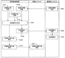
図1は、本発明の実施の形態1に係るシステム構成を説明するための概念構成図である。図1に示す発電設備10は、電力系統の送電設備20に接続する。電力系統には、送電設備20の他、送電設備20に接続された他の発電設備(図示省略)、送電設備20に接続された負荷設備(図示省略)が含まれる。Embodiment 1 FIG.
[System Configuration of Embodiment 1]
FIG. 1 is a conceptual configuration diagram for explaining a system configuration according to Embodiment 1 of the present invention. The
また、発電設備10は、天候によって発電電力が変動する発電システム30と、蓄電池を有する蓄電池システム40と、発電システム30と蓄電池システム40と電力系統とを接続する設備内電線21を備える。なお、発電設備10において、蓄電池システム40の定格出力(蓄電池システム40が充放電可能な最大電力)は、発電システム30の定格出力(発電システム30が供給可能な最大電力)よりも小さい。
Further, the
さらに、発電設備10は、統括制御装置50を備える。統括制御装置50は、コンピュータネットワーク22を介して発電システム30および蓄電池システム40と接続する。発電設備10と電力系統との連系点には電力計25が設けられる。電力計25は、信号線により統括制御装置50に接続する。
Furthermore, the
(発電システム)
図1に示す発電システム30は、太陽光発電(PV)システムである。なお、発電システム30は、風力発電システム等であってもよい。発電システム30は、太陽光発電装置31、太陽光発電用のパワーコンディショニングシステム(以下、PV−PCS)32、電力計33を備える。太陽光発電装置31は、複数のPVモジュール311、複数のPVモジュール311が接続する接続箱312、複数の接続箱312が接続する集電箱313を備える。集電箱313はPV−PCS32に接続する。複数のPVモジュール311で発電された電力は、集電箱313を介してPV−PCS32に供給される。(Power generation system)
The
PV−PCS32は、太陽光発電装置31から供給される直流電力を交流電力に変換する機能を備える。また、PV−PCS32は、電流センサと電圧センサとを備え、これらのセンサの出力値を参照して電力の調整を実施する。PV−PCS32は設備内電線21に接続する。電力計33は、信号線により統括制御装置50に接続する。発電システム30は、コンピュータネットワーク22を介して蓄電池システム40、統括制御装置50に接続する。
The PV-
電力計33は、発電システム30から設備内電線21に供給される供給電力を常時検出する。ただし、本実施の形態でいう常時検出とは、センサから絶え間のない連続した信号を取り込む動作だけでなく、所定の短い周期でセンサの信号を取り込む動作を含む概念である。電力計33で検出された供給電力値は統括制御装置50に入力される。
The
(蓄電池システム)
蓄電池システム40は、蓄電池装置41、蓄電池用のパワーコンディショニングシステム(以下、蓄電池用PCS)42を備える。図1に示す蓄電池システム40は、1つの蓄電池用PCS42に対して1つの蓄電池装置41が接続されているが、これは単なる一例である。一般に、1つの蓄電池用PCS42に対して複数の蓄電池装置41が並列に接続される。蓄電池装置41の並列数は蓄電池用PCS42の仕様に基づいて定められる。蓄電池システム40は、コンピュータネットワーク22を介して発電システム30、統括制御装置50に接続する。(Storage battery system)
The
蓄電池装置41は、蓄電池モジュール411、及び蓄電池監視装置(以下、BMU:Battery Management Unit)412を備える。蓄電池モジュール411は、複数のセルが直列に接続されたモジュールである。各セルはリチウムイオン電池(LiB)である。蓄電池モジュール411は、コンタクタ及びヒューズを介して送電線により蓄電池用PCS42に接続する。また、蓄電池モジュール411は、信号線によりBMU412に接続する。BMU412は、コンピュータネットワーク22を介して統括制御装置50に接続する。
The
BMU412は、蓄電池モジュール411の状態を監視する。具体的には、BMU412は、蓄電池モジュール411の状態量を計測する手段として電流センサ、電圧センサ、及び温度センサを備える。電流センサによって蓄電池モジュール411に流れる電流が計測される。電圧センサによって各セルの電圧が計測される。そして、温度センサによって蓄電池モジュール411の温度が計測される。BMU412による蓄電池モジュール411の監視は常時行われる。ただし、本実施の形態でいう常時監視とは、センサから絶え間のない連続した信号を取り込む動作だけでなく、所定の短い周期でセンサの信号を取り込む動作を含む概念である。BMU412は、各センサによる計測で得られた情報を含む蓄電池情報を統括制御装置50に送信する。
The
蓄電池用PCS42は、変圧器を介して送電線により設備内電線21に接続される。蓄電池用PCS42は、発電システム30が出力した交流電力を直流電力に変換して蓄電池モジュール411に充電する充電機能と、蓄電池モジュール411の直流電力を交流電力に変換して電力系統に放電する放電機能とを備える。蓄電池モジュール411への充電電力量、及び蓄電池モジュール411からの放電電力量は、蓄電池用PCS42によって調整される。蓄電池用PCS42による充放電電力量の調整は、統括制御装置50から供給される充放電指令に従って行われる。充放電指令は、蓄電池用PCS42に充放電させる有効電力と無効電力に関する要求を含む。蓄電池用PCS42は電流センサと電圧センサとを備え、蓄電池用PCS42はこれらのセンサの出力値を参照して充放電電力量の調整を実施する。
The
(統括制御装置)
統括制御装置50は、コンピュータネットワーク22を介して発電システム30、蓄電池システム40に接続する。統括制御装置50は、電力系統と発電設備10との間の電力需給を制御する。例えば、統括制御装置50は、後述する充放電指令部60や発電許容電力値算出部61を備える。(General control device)
The
電力計25は、発電設備10から電力系統に供給される合成電力を常時検出する。合成電力は、発電システム30が供給する電力と蓄電池システム40の充放電電力とを合算した電力である。ただし、本実施の形態でいう常時検出とは、センサから絶え間のない連続した信号を取り込む動作だけでなく、所定の短い周期でセンサの信号を取り込む動作を含む概念である。電力計25で検出された合成電力値は統括制御装置50に入力される。
The
[実施の形態1の特徴的構成]
図2は、本発明の実施の形態1に係るシステムのブロック図である。本発明に係る発電制御装置1は、統括制御装置50と発電システム30の一部を含みうる概念である。[Characteristic Configuration of Embodiment 1]
FIG. 2 is a block diagram of a system according to Embodiment 1 of the present invention. The power generation control device 1 according to the present invention is a concept that may include a part of the
統括制御装置50を示すブロック内には、発電制御装置1が備える種々の機能のうちの一部がブロックで表されている。同様に、発電システム30を示すブロック内には、発電制御装置1が備える種々の機能のうちの一部がブロックで表わされている。
In the block indicating the
(充放電指令部)
発電制御装置1は、充放電指令機能を有し、その機能は充放電指令部60が受け持つ。発電制御装置1は、電力計25から合成電力値を受信し、電力計33から供給電力値を受信し、蓄電池システム40(BMU412)から蓄電池情報を受信する。充放電指令部60は、合成電力値と供給電力値と蓄電池情報とに基づいて充放電指令を決定し、充放電指令を蓄電池システム40に送信する。(Charge / discharge command section)
The power generation control device 1 has a charge / discharge command function, and the charge /
図3は、太陽光発電システムによる時刻毎の発電電力の変動について説明するための図である。太陽光発電システムの出力は日射量によって変動する。典型的なのが、晴天時に雲が流れている場合で、雲の影が太陽光パネルの上を通過する過程で、出力が短時間で激しく変動する。太陽光発電の出力変動を打ち消すように蓄電池システム40に充放電させることで、急峻な変動を平準化する必要がある。
FIG. 3 is a diagram for explaining the fluctuation of the generated power for each time by the solar power generation system. The output of the solar power generation system varies depending on the amount of solar radiation. A typical case is when a cloud is flowing in fine weather, and the output fluctuates rapidly in a short time as the shadow of the cloud passes over the solar panel. It is necessary to level the steep fluctuations by charging / discharging the
図3に示す例では、破線301に示す太陽光発電システムの出力を相殺するように、蓄電池システム40に充放電させることで、実線302のように出力変動が緩和される。充放電指令部60は、太陽光発電の急峻な出力変動を、蓄電池システム40の充放電制御により平準化させるように充放電指令を決定する。
In the example illustrated in FIG. 3, the output fluctuation is reduced as indicated by the
具体的には、発電設備10には、電力系統に安定した電力供給を行うために、発電設備10の定格出力(発電設備10が電力系統に供給可能な最大電力)に対する電力系統に供給される電力の変化率(以下、系統供給電力変化率という。)を、±n%/分の範囲内に制御することが要求されている。そのため、充放電指令部60は、電力系統に供給される電力の1制御周期あたりの変化が、発電設備の定格出力の規定割合以内に収まるように、蓄電池システム40に対する充放電指令を決定する。例えば、発電システム30が設備内電線21に供給する電力が増大する制御周期においては、充放電指令部60は、発電システム30が設備内電線21に供給する電力の一部を蓄電池システム40に充電させる充放電指令を決定する。なお、制御周期は数ミリ秒〜数十ミリ秒に設定される。一例として、制御周期が20ミリ秒の場合、上記規定割合は、n%の3000分の1である。
Specifically, the
(発電許容電力値算出部)
図4は、制御周期毎の発電システム30の出力と、発電許容電力値の算出について説明するための図である。実線71は、制御周期毎の発電システム30の出力を示す。点72は、現制御周期におけるサイト出力(発電設備10が電力系統に供給する電力)である。点74は、次制御周期におけるサイト出力である。また、点72は、現制御周期におけるサイト出力上限許容値であり、点73は、現制御周期におけるサイト出力下限許容値である。サイト出力上限許容値は、系統供給電力変化率の最大値(+n%/分)に対応する値である。サイト出力下限許容値は、系統供給電力変化率の最小値(−n%/分)に対応する値である。また、図4に示す(A)〜(E)は以下のように定義される。
(A)は、現制御周期において、発電システム30が設備内電線21に供給する電力の現在値であり、電力計33により検出される。
(B)は、蓄電池システム40が充電する電力の現在値であり、充放電指令部60により算出される充放電指令に含まれる。
(C)は、発電設備10の定格出力の規定割合に応じた電力値である。規定割合は、系統供給電力変化率の最大値と制御周期に応じて予め設定された固定値である。
(D)は、蓄電池システム40の1制御周期あたりの充電電力の最大値であり、蓄電池用PCS42の定格出力として予め設定された固定値である。
(E)は、次制御周期における発電許容電力値であり、次制御周期における発電許容電力値は、上記(A)〜(E)を用いて次式(1)で表わされる。
(E)=(A)−(B)+(C)+(D) ・・・(1)(Power generation allowable power value calculation unit)
FIG. 4 is a diagram for explaining the output of the
(A) is the current value of the electric power supplied from the
(B) is the current value of the power charged by the
(C) is a power value according to a specified ratio of the rated output of the
(D) is the maximum value of the charging power per control cycle of the
(E) is a power generation allowable power value in the next control cycle, and the power generation allowable power value in the next control cycle is expressed by the following equation (1) using the above (A) to (E).
(E) = (A)-(B) + (C) + (D) (1)
発電制御装置1は、発電許容電力値算出機能を有し、その機能は発電許容電力値算出部61が受け持つ。発電許容電力値算出部61は、式(1)を用いて、次制御周期における発電許容電力値を算出する。算出された発電許容電力値は、出力抑制部62に送信される。
The power generation control device 1 has a power generation allowable power value calculation function, and the power generation allowable power
(出力抑制部)
発電制御装置1は、出力抑制機能を有し、その機能は出力抑制部62が受け持つ。出力抑制部62は、制御周期毎に、太陽光発電装置31からPV−PCS32に供給される発電電力が発電許容電力値よりも大きいかを判定する。太陽光発電装置31からPV−PCS32に供給される発電電力は、PV−PCS32内の電流センサと電圧センサの出力値から算出される。判定に用いられる発電許容電力値は、出力抑制部62の処理が実行される1つ前の制御周期において発電許容電力値算出部61により算出された値である。(Output suppression unit)
The power generation control device 1 has an output suppression function, and the
太陽光発電装置31からPV−PCS32に供給される発電電力が発電許容電力値以下である場合には、急激に増大した電力を蓄電池システム40に充電させることで、系統供給電力変化率を±n%/分以内に制御することが可能である。一方、太陽光発電装置31からPV−PCS32に供給される発電電力が発電許容電力値よりも大きい場合には、蓄電池システム40の充電能力不足のため、急激に増大した電力を蓄電池システム40に充電させるだけでは、系統供給電力変化率を±n%/分以内に制御することができない。
When the generated power supplied from the solar
図5は、本発明の実施の形態1における出力抑制制御について説明するための図である。次制御周期において、太陽光発電装置31からPV−PCS32に供給される発電電力が発電許容電力値よりも大きい場合には、破線75で示すような発電システム30の出力を回避するため、出力抑制部62は、発電システム30が設備内電線21に供給する電力を発電許容電力値以下に抑制する出力抑制制御を実行する(矢印76)。具体的には、出力抑制部62は、PV−PCS32に対して、PV−PCS32が設備内電線21に供給する電力を発電許容電力値以下に抑制させる制御を実行する。
FIG. 5 is a diagram for describing output suppression control according to Embodiment 1 of the present invention. In the next control cycle, when the generated power supplied from the photovoltaic
(フローチャート)
図6は、発電制御装置1の充放電指令部60および発電許容電力値算出部61の処理について説明するためのフローチャートである。図6に示す制御ルーチンは制御周期毎に実行される。(flowchart)
FIG. 6 is a flowchart for explaining the processing of the charge /
電力計33は、発電システム30から設備内電線21に供給される供給電力を常時検出する。統括制御装置50は、電力計33により検出された供給電力値を制御周期毎に取得する(ステップS101)。
The
電力計25は、発電設備10から電力系統に供給される合成電力を常時検出する。統括制御装置50は、電力計25により検出された合成電力値を制御周期毎に取得する(ステップS102)。
The
蓄電池システム40は、蓄電池情報を統括制御装置50に送信する(ステップS301)。蓄電池情報には、蓄電池モジュール411に流れる電流、各セルの電圧、蓄電池モジュール411の温度が含まれる。統括制御装置50は、蓄電池システム40から送信された蓄電池情報を制御周期毎に受信する(ステップS103)。
The
ステップS101〜S103の処理後、充放電指令部60は充放電指令を決定する(ステップS104)。具体的には、充放電指令部60は、ステップS101において取得した供給電力と、ステップS102において取得した合成電力と、ステップS103において取得した蓄電池情報とに基づいて、系統供給電力変化率が±n%/分の変動範囲内に収まるように充放電指令を決定する。例えば、発電システム30が設備内電線21に供給する電力が増大する制御周期においては、発電システム30が設備内電線21に供給する電力の一部を蓄電池システム40に充電させる充放電指令が決定される。
After the processes in steps S101 to S103, the charge /
ステップS104の処理後、充放電指令部60は、充放電指令を蓄電池システム40に送信する(ステップS105)。蓄電池システム40は、統括制御装置50から送信された充放電指令を受信する(ステップS302)。蓄電池用PCS42は、受信した充放電指令に従って充放電操作を実行する(ステップS303)
After the process of step S104, the charge /
ステップS104の処理後、発電許容電力値算出部61は、現制御周期においてステップS101、S103、S104で得られた値と、上述した式(1)を用いて、次制御周期における発電許容電力値を算出する(ステップS106)。
After the process of step S104, the power generation allowable power
ステップS106の処理後、統括制御装置50は、発電許容電力値を発電システム30に送信する(ステップS107)。発電システム30は、統括制御装置50から送信された発電許容電力値を受信する(ステップS201)。
After the process of step S106, the
図7は、発電制御装置1の出力抑制部62の処理について説明するためのフローチャートである。図7に示す制御ルーチンは制御周期毎に実行される。ここでは、図6に示す制御ルーチンが実行された制御周期の次の制御周期における処理について説明する。
FIG. 7 is a flowchart for explaining processing of the
出力抑制部62は、太陽光発電装置31からPV−PCS32に供給される発電電力を取得する(ステップS210)。また、出力抑制部62は、図7に示す制御ルーチンが実行される1つ前の制御周期において図6のステップS201において受信した発電許容電力値を、出力抑制部62に設定する。
The
ステップS210およびS211の処理後、出力抑制部62は、太陽光発電装置31からPV−PCS32に供給される発電電力が発電許容電力値よりも大きいかを判定する(ステップS212)。
After the processing of steps S210 and S211, the
太陽光発電装置31からPV−PCS32に供給される発電電力が発電許容電力値よりも大きい場合には、出力抑制部62は、発電システム30が設備内電線21に供給する電力を発電許容電力値以下に抑制する(ステップS213)。
When the generated power supplied from the solar
一方、太陽光発電装置31からPV−PCS32に供給される発電電力が発電許容電力値以下である場合には、出力抑制部62は、出力を抑制する制御を実行しない(ステップS214)。
On the other hand, when the generated power supplied from the solar
以上説明したように、本実施形態のシステムによれば、発電制御装置1は、制御周期毎に、次制御周期における最適な発電許容電力値を算出できる。そして、次制御周期において、太陽光発電装置31から供給される電力が発電許容電力値よりも大きい場合に、発電システム30が設備内電線21に供給する電力を発電許容電力値以下に抑制する。制御周期毎に次制御周期における最適な発電許容電力値が算出されるため、蓄電池システム40の定格出力が発電システム30の定格出力より低い発電設備10において、急峻な発電電力の変化(1制御周期で上述した(C)+(D)を超える電力変化)があった場合にも、電力系統に供給される電力の1制御周期あたりの変化を発電設備10の定格出力の規定割合以内に収めることができる。すなわち、蓄電池システム40の能力が低い、コストが低い発電設備10において、電力系統に安定した電力供給を行うことができる。
As described above, according to the system of the present embodiment, the power generation control device 1 can calculate the optimum power generation allowable power value in the next control cycle for each control cycle. And in the next control period, when the electric power supplied from the solar
また、本発明によれば、制御周期毎に最適な発電許容電力値が算出されるため、各制御周期において出力抑制を必要最低限とすることができる。そのため、出力抑制スケジュールが予め定められている場合に比して、不必要な発電電力の抑制が少なく、発電効率を高めることが可能である。 Further, according to the present invention, since an optimum power generation allowable power value is calculated for each control cycle, output suppression can be minimized in each control cycle. Therefore, compared with the case where an output suppression schedule is determined in advance, unnecessary generation power is suppressed less, and power generation efficiency can be increased.
尚、実施の形態1において、符号60〜62に示す各部は、発電制御装置1が有する機能を示す。図8は、発電制御装置1のハードウェア構成を示す図である。発電制御装置1は、ハードウェア資源として、各種情報を入出力する入出力インタフェース(図示省略)、各種情報および各種プログラムを記憶するメモリ201、メモリ201に記憶された各種情報および各種プログラムに基づいて演算処理を実行可能なプロセッサ200を含む回路を備える。発電制御装置1は、メモリ201に記憶されたプログラムをプロセッサ200によって実行することにより各部60〜62が有する各機能を実現する。発電制御装置1は、複数のプロセッサ200を備えても良い。発電制御装置1は、複数のメモリ201を備えても良い。発電制御装置1は、複数の入出力インタフェースを備えても良い。即ち、複数のプロセッサ200と複数のメモリ201と複数の入出力インタフェースが連携して各部60〜62が有する各機能を実現しても良い。また、各部60〜62が有する各機能の一部又は全部は、回路によって構成されてもよい。
In the first embodiment, each part indicated by
なお、図2に示すように、発電制御装置1は、統括制御装置50と発電システム30とがコンピュータネットワーク22で接続されて構成されてもよい。この場合、統括制御装置50、発電システム30がそれぞれプロセッサ、メモリ、入出力インタフェースを有する。
As shown in FIG. 2, the power generation control device 1 may be configured by connecting the
1 発電制御装置
10 発電設備
20 電力系統の送電設備
21 設備内電線
22 コンピュータネットワーク
25 電力計
30 発電システム
31 太陽光発電装置
32 PV−PCS
33 電力計
40 蓄電池システム
41 蓄電池装置
42 蓄電池用PCS
50 統括制御装置
60 充放電指令部
61 発電許容電力値算出部
62 出力抑制部
200 プロセッサ
201 メモリ
311 PVモジュール
312 接続箱
313 集電箱
411 蓄電池モジュール
412 BMUDESCRIPTION OF SYMBOLS 1 Power
33
50
Claims (4)
蓄電池を有する蓄電池システムと、
前記発電システムと蓄電池システムと電力系統とを接続する設備内電線とを備え、
前記電力系統に供給される電力の1制御周期あたりの変化が、定格出力の規定割合以内に収まるように、前記発電システムが前記設備内電線に供給する電力の一部を前記蓄電池システムに充電させる発電設備であって、
前記発電システムが前記設備内電線に供給する電力の現在値から前記蓄電池システムが充電する電力の現在値を減じた値に、前記定格出力の前記規定割合に応じた電力値と、前記蓄電池システムの前記1制御周期あたりの充電電力の最大値とを加えた発電許容電力値を算出する発電許容電力値算出手段と、
次制御周期において、前記発電装置から供給される電力が前記発電許容電力値よりも大きい場合に、前記発電システムが前記設備内電線に供給する電力を前記発電許容電力値以下に抑制する出力抑制手段と、を有する発電制御装置を備えること、
を特徴とする発電設備。A power generation system having a power generation device whose generated power fluctuates depending on the weather;
A storage battery system having a storage battery;
An electric wire in the facility for connecting the power generation system, the storage battery system, and the power system;
The storage battery system is charged with a part of the power that the power generation system supplies to the in-facility wires so that the change per control cycle of the power supplied to the power system falls within a specified ratio of the rated output. Power generation equipment,
A value obtained by subtracting a current value of power charged by the storage battery system from a current value of power supplied to the electric wire in the facility by the power generation system, a power value corresponding to the specified ratio of the rated output, and the storage battery system A power generation allowable power value calculating means for calculating a power generation allowable power value obtained by adding the maximum value of the charging power per control cycle;
In the next control cycle, when the power supplied from the power generation device is larger than the power generation allowable power value, the output suppression means that suppresses the power supplied to the electric wire in the facility by the power generation system below the power generation allowable power value. A power generation control device having
Power generation equipment characterized by
を特徴とする請求項1記載の発電設備。The rated output of the storage battery system is smaller than the rated output of the power generation system,
The power generation facility according to claim 1.
蓄電池を有する蓄電池システムと、
前記発電システムと蓄電池システムと電力系統とを接続する設備内電線とを備え、
前記電力系統に供給される電力の1制御周期あたりの変化が、定格出力の規定割合以内に収まるように、前記発電システムが供給する電力の一部を前記蓄電池システムに充電させる発電設備に設けられる発電制御装置であって、
前記発電システムが前記設備内電線に供給する電力の現在値から前記蓄電池システムが充電する電力の現在値を減じた値に、前記定格出力の前記規定割合に応じた電力値と、前記蓄電池システムの前記1制御周期あたりの充電電力の最大値とを加えた発電許容電力値を算出する発電許容電力値算出手段と、
次制御周期において、前記発電装置から供給される電力が前記発電許容電力値よりも大きい場合に、前記発電システムが前記設備内電線に供給する電力を前記発電許容電力値以下に抑制する出力抑制手段と、
を備えることを特徴とする発電制御装置。A power generation system having a power generation device whose generated power fluctuates depending on the weather;
A storage battery system having a storage battery;
An electric wire in the facility for connecting the power generation system, the storage battery system, and the power system;
Provided in a power generation facility that charges the storage battery system with a part of the power supplied by the power generation system so that the change per control cycle of the power supplied to the power system falls within a specified ratio of the rated output. A power generation control device,
A value obtained by subtracting a current value of power charged by the storage battery system from a current value of power supplied to the electric wire in the facility by the power generation system, a power value corresponding to the specified ratio of the rated output, and the storage battery system A power generation allowable power value calculating means for calculating a power generation allowable power value obtained by adding the maximum value of the charging power per control cycle;
In the next control cycle, when the power supplied from the power generation device is larger than the power generation allowable power value, the output suppression means that suppresses the power supplied to the electric wire in the facility by the power generation system below the power generation allowable power value. When,
A power generation control device comprising:
を特徴とする請求項3記載の発電制御装置。The rated output of the storage battery system is smaller than the rated output of the power generation system,
The power generation control device according to claim 3.
Applications Claiming Priority (1)
| Application Number | Priority Date | Filing Date | Title |
|---|---|---|---|
| PCT/JP2015/074845 WO2017037868A1 (en) | 2015-09-01 | 2015-09-01 | Power generation facility and power generation control device |
Publications (2)
| Publication Number | Publication Date |
|---|---|
| JP5896096B1 true JP5896096B1 (en) | 2016-03-30 |
| JPWO2017037868A1 JPWO2017037868A1 (en) | 2017-09-07 |
Family
ID=55628598
Family Applications (1)
| Application Number | Title | Priority Date | Filing Date |
|---|---|---|---|
| JP2015562227A Active JP5896096B1 (en) | 2015-09-01 | 2015-09-01 | Power generation equipment and power generation control device |
Country Status (4)
| Country | Link |
|---|---|
| US (1) | US10476272B2 (en) |
| JP (1) | JP5896096B1 (en) |
| CN (1) | CN108028546B (en) |
| WO (1) | WO2017037868A1 (en) |
Families Citing this family (14)
| Publication number | Priority date | Publication date | Assignee | Title |
|---|---|---|---|---|
| US10541451B2 (en) | 2012-10-18 | 2020-01-21 | Ambri Inc. | Electrochemical energy storage devices |
| US11721841B2 (en) | 2012-10-18 | 2023-08-08 | Ambri Inc. | Electrochemical energy storage devices |
| WO2015058010A1 (en) | 2013-10-16 | 2015-04-23 | Ambri Inc. | Seals for high temperature reactive material devices |
| US11387497B2 (en) | 2012-10-18 | 2022-07-12 | Ambri Inc. | Electrochemical energy storage devices |
| US11211641B2 (en) | 2012-10-18 | 2021-12-28 | Ambri Inc. | Electrochemical energy storage devices |
| US12142735B1 (en) | 2013-11-01 | 2024-11-12 | Ambri, Inc. | Thermal management of liquid metal batteries |
| US10181800B1 (en) * | 2015-03-02 | 2019-01-15 | Ambri Inc. | Power conversion systems for energy storage devices |
| WO2016141354A2 (en) | 2015-03-05 | 2016-09-09 | Ambri Inc. | Ceramic materials and seals for high temperature reactive material devices |
| WO2017149618A1 (en) * | 2016-02-29 | 2017-09-08 | 日本電気株式会社 | Control device, power generation control device, control method, system, and program |
| US11929466B2 (en) | 2016-09-07 | 2024-03-12 | Ambri Inc. | Electrochemical energy storage devices |
| JP7201613B2 (en) | 2017-04-07 | 2023-01-10 | アンブリ・インコーポレイテッド | Molten salt battery with solid metal cathode |
| JP2022513918A (en) | 2018-12-17 | 2022-02-09 | アンブリ・インコーポレイテッド | High temperature energy storage system and method |
| JP7411909B2 (en) * | 2020-02-28 | 2024-01-12 | パナソニックIpマネジメント株式会社 | Power management system, power management method, and program |
| JP2024164545A (en) * | 2023-05-15 | 2024-11-27 | 株式会社日立製作所 | Power management system and power control system |
Citations (6)
| Publication number | Priority date | Publication date | Assignee | Title |
|---|---|---|---|---|
| JP2006174694A (en) * | 2004-12-17 | 2006-06-29 | General Electric Co <Ge> | Control method and control system of wind turbine generator |
| WO2011122681A1 (en) * | 2010-03-30 | 2011-10-06 | 三洋電機株式会社 | System-stabilizing system, power supply system, method for controlling central management device, and program for central management device |
| JP2013176234A (en) * | 2012-02-27 | 2013-09-05 | Hitachi Ltd | Stand-alone power supply system |
| JP2013179737A (en) * | 2012-02-28 | 2013-09-09 | Mitsubishi Heavy Ind Ltd | Output smoothing device, output smoothing method, and program |
| WO2014071459A1 (en) * | 2012-11-09 | 2014-05-15 | Mpower Projects Pty Ltd | Grid stability control system and method |
| JP2014200120A (en) * | 2011-08-12 | 2014-10-23 | シャープ株式会社 | Hybrid independent power generation system |
Family Cites Families (7)
| Publication number | Priority date | Publication date | Assignee | Title |
|---|---|---|---|---|
| JP2002204531A (en) * | 2000-10-31 | 2002-07-19 | Canon Inc | Ac-interconnecting device and control method thereof |
| JP4213941B2 (en) * | 2002-10-11 | 2009-01-28 | シャープ株式会社 | Output control method for a plurality of distributed power supplies and distributed power management system |
| US8237301B2 (en) * | 2008-01-31 | 2012-08-07 | General Electric Company | Power generation stabilization control systems and methods |
| JP5372724B2 (en) * | 2009-12-21 | 2013-12-18 | 株式会社日立製作所 | Power generation system using natural energy |
| KR20120132300A (en) * | 2011-02-10 | 2012-12-05 | 미츠비시 쥬고교 가부시키가이샤 | Wind power generating equipment and control method thereof |
| JP2012249476A (en) * | 2011-05-30 | 2012-12-13 | Panasonic Corp | Power supply system |
| JP2017117003A (en) | 2015-12-21 | 2017-06-29 | 株式会社リコー | Control device and start-up control method |
-
2015
- 2015-09-01 WO PCT/JP2015/074845 patent/WO2017037868A1/en active Application Filing
- 2015-09-01 JP JP2015562227A patent/JP5896096B1/en active Active
- 2015-09-01 CN CN201580082780.1A patent/CN108028546B/en active Active
- 2015-09-01 US US15/741,316 patent/US10476272B2/en active Active
Patent Citations (6)
| Publication number | Priority date | Publication date | Assignee | Title |
|---|---|---|---|---|
| JP2006174694A (en) * | 2004-12-17 | 2006-06-29 | General Electric Co <Ge> | Control method and control system of wind turbine generator |
| WO2011122681A1 (en) * | 2010-03-30 | 2011-10-06 | 三洋電機株式会社 | System-stabilizing system, power supply system, method for controlling central management device, and program for central management device |
| JP2014200120A (en) * | 2011-08-12 | 2014-10-23 | シャープ株式会社 | Hybrid independent power generation system |
| JP2013176234A (en) * | 2012-02-27 | 2013-09-05 | Hitachi Ltd | Stand-alone power supply system |
| JP2013179737A (en) * | 2012-02-28 | 2013-09-09 | Mitsubishi Heavy Ind Ltd | Output smoothing device, output smoothing method, and program |
| WO2014071459A1 (en) * | 2012-11-09 | 2014-05-15 | Mpower Projects Pty Ltd | Grid stability control system and method |
Also Published As
| Publication number | Publication date |
|---|---|
| CN108028546A (en) | 2018-05-11 |
| US10476272B2 (en) | 2019-11-12 |
| WO2017037868A1 (en) | 2017-03-09 |
| US20180191162A1 (en) | 2018-07-05 |
| JPWO2017037868A1 (en) | 2017-09-07 |
| CN108028546B (en) | 2020-09-08 |
Similar Documents
| Publication | Publication Date | Title |
|---|---|---|
| JP5896096B1 (en) | Power generation equipment and power generation control device | |
| JP6304392B2 (en) | Charge / discharge management device | |
| JP6384482B2 (en) | Battery system | |
| JP5520365B2 (en) | System stabilization system, power supply system, centralized management device control method, and centralized management device program | |
| JP6327356B2 (en) | Battery system | |
| CN107078514B (en) | Battery system | |
| JP6249022B2 (en) | Battery system | |
| JP2014124063A (en) | Storage battery state of charge management device | |
| JP6481694B2 (en) | Battery capacity measuring device | |
| JP6288096B2 (en) | Battery system | |
| WO2015040723A1 (en) | Storage battery system | |
| WO2016063351A1 (en) | Charge/discharge management device | |
| JP6174844B2 (en) | Power supply control device | |
| JP6895145B2 (en) | Power control device and its control method | |
| JP6922800B2 (en) | Storage battery system and its charge / discharge loss arithmetic unit | |
| JP2020018082A (en) | Power control system |
Legal Events
| Date | Code | Title | Description |
|---|---|---|---|
| A621 | Written request for application examination |
Free format text: JAPANESE INTERMEDIATE CODE: A621 Effective date: 20151222 |
|
| A871 | Explanation of circumstances concerning accelerated examination |
Free format text: JAPANESE INTERMEDIATE CODE: A871 Effective date: 20151222 |
|
| TRDD | Decision of grant or rejection written | ||
| A975 | Report on accelerated examination |
Free format text: JAPANESE INTERMEDIATE CODE: A971005 Effective date: 20160127 |
|
| A01 | Written decision to grant a patent or to grant a registration (utility model) |
Free format text: JAPANESE INTERMEDIATE CODE: A01 Effective date: 20160202 |
|
| A61 | First payment of annual fees (during grant procedure) |
Free format text: JAPANESE INTERMEDIATE CODE: A61 Effective date: 20160215 |
|
| R150 | Certificate of patent or registration of utility model |
Ref document number: 5896096 Country of ref document: JP Free format text: JAPANESE INTERMEDIATE CODE: R150 |
|
| R250 | Receipt of annual fees |
Free format text: JAPANESE INTERMEDIATE CODE: R250 |
|
| R250 | Receipt of annual fees |
Free format text: JAPANESE INTERMEDIATE CODE: R250 |
|
| R250 | Receipt of annual fees |
Free format text: JAPANESE INTERMEDIATE CODE: R250 |
|
| R250 | Receipt of annual fees |
Free format text: JAPANESE INTERMEDIATE CODE: R250 |
|
| R250 | Receipt of annual fees |
Free format text: JAPANESE INTERMEDIATE CODE: R250 |
|
| R250 | Receipt of annual fees |
Free format text: JAPANESE INTERMEDIATE CODE: R250 |
|
| R250 | Receipt of annual fees |
Free format text: JAPANESE INTERMEDIATE CODE: R250 |