JP5893756B2 - Hybrid ion source, mass spectrometer and ion mobility device - Google Patents
Hybrid ion source, mass spectrometer and ion mobility device Download PDFInfo
- Publication number
- JP5893756B2 JP5893756B2 JP2014550104A JP2014550104A JP5893756B2 JP 5893756 B2 JP5893756 B2 JP 5893756B2 JP 2014550104 A JP2014550104 A JP 2014550104A JP 2014550104 A JP2014550104 A JP 2014550104A JP 5893756 B2 JP5893756 B2 JP 5893756B2
- Authority
- JP
- Japan
- Prior art keywords
- ion source
- hybrid
- electrode
- ions
- esi
- Prior art date
- Legal status (The legal status is an assumption and is not a legal conclusion. Google has not performed a legal analysis and makes no representation as to the accuracy of the status listed.)
- Active
Links
Images


Classifications
-
- H—ELECTRICITY
- H01—ELECTRIC ELEMENTS
- H01J—ELECTRIC DISCHARGE TUBES OR DISCHARGE LAMPS
- H01J49/00—Particle spectrometers or separator tubes
- H01J49/02—Details
- H01J49/10—Ion sources; Ion guns
- H01J49/107—Arrangements for using several ion sources
-
- G—PHYSICS
- G01—MEASURING; TESTING
- G01N—INVESTIGATING OR ANALYSING MATERIALS BY DETERMINING THEIR CHEMICAL OR PHYSICAL PROPERTIES
- G01N27/00—Investigating or analysing materials by the use of electric, electrochemical, or magnetic means
- G01N27/62—Investigating or analysing materials by the use of electric, electrochemical, or magnetic means by investigating the ionisation of gases, e.g. aerosols; by investigating electric discharges, e.g. emission of cathode
- G01N27/622—Ion mobility spectrometry
- G01N27/623—Ion mobility spectrometry combined with mass spectrometry
-
- H—ELECTRICITY
- H01—ELECTRIC ELEMENTS
- H01J—ELECTRIC DISCHARGE TUBES OR DISCHARGE LAMPS
- H01J49/00—Particle spectrometers or separator tubes
- H01J49/02—Details
- H01J49/10—Ion sources; Ion guns
- H01J49/16—Ion sources; Ion guns using surface ionisation, e.g. field-, thermionic- or photo-emission
- H01J49/165—Electrospray ionisation
-
- H—ELECTRICITY
- H01—ELECTRIC ELEMENTS
- H01J—ELECTRIC DISCHARGE TUBES OR DISCHARGE LAMPS
- H01J49/00—Particle spectrometers or separator tubes
- H01J49/02—Details
- H01J49/10—Ion sources; Ion guns
- H01J49/16—Ion sources; Ion guns using surface ionisation, e.g. field-, thermionic- or photo-emission
- H01J49/168—Ion sources; Ion guns using surface ionisation, e.g. field-, thermionic- or photo-emission field ionisation, e.g. corona discharge
Landscapes
- Physics & Mathematics (AREA)
- Chemical & Material Sciences (AREA)
- Engineering & Computer Science (AREA)
- Plasma & Fusion (AREA)
- Analytical Chemistry (AREA)
- Life Sciences & Earth Sciences (AREA)
- Health & Medical Sciences (AREA)
- Spectroscopy & Molecular Physics (AREA)
- Electrochemistry (AREA)
- Chemical Kinetics & Catalysis (AREA)
- Biochemistry (AREA)
- General Health & Medical Sciences (AREA)
- General Physics & Mathematics (AREA)
- Immunology (AREA)
- Pathology (AREA)
- Molecular Biology (AREA)
- Other Investigation Or Analysis Of Materials By Electrical Means (AREA)
- Electron Tubes For Measurement (AREA)
Description
本発明は、イオン化方式を異にする複数種類のイオン源を搭載するハイブリッドイオン源と、当該イオン源を搭載する質量分析計及びイオンモビリティ装置に関する。 The present invention relates to a hybrid ion source equipped with a plurality of types of ion sources having different ionization methods, a mass spectrometer equipped with the ion source, and an ion mobility apparatus.
大気圧イオン化質量分析計は、大気圧下で生成したイオンを真空系に導入してイオンの質量を分析する。大気圧イオン化法には、エレクトロスプレー法(以下「ESI法」という。)、大気圧化学イオン化法(以下「APCI法」という。)等がある。 An atmospheric pressure ionization mass spectrometer introduces ions generated under atmospheric pressure into a vacuum system and analyzes the mass of the ions. The atmospheric pressure ionization method includes an electrospray method (hereinafter referred to as “ESI method”), an atmospheric pressure chemical ionization method (hereinafter referred to as “APCI method”), and the like.
ESI法は、高電圧を印加したキャピラリーに試料溶液を流して噴霧することにより帯電液滴を生成し、この帯電液滴が蒸発と分裂を繰り返すことによりイオンを生成する方式である。ESI法は、高分子量試料や高極性試料などに対応可能なイオン化法である。なお、ESI法では、一般に、加熱したガスなどを大量に噴霧して液滴の蒸発・気化を促進させる方式が併用される。 The ESI method is a method in which charged liquid droplets are generated by flowing and spraying a sample solution through a capillary to which a high voltage is applied, and ions are generated by repeating evaporation and splitting of the charged liquid droplets. The ESI method is an ionization method that can be applied to a high molecular weight sample, a high polarity sample, and the like. In the ESI method, generally, a method of spraying a large amount of heated gas or the like to promote evaporation and vaporization of droplets is used in combination.
APCI法は、試料溶液を加熱気化した溶媒分子をコロナ放電によりイオン化する方式である。この方式の場合、コロナ放電により生成された一次イオンと試料分子の間で電荷の移動が生じ、試料分子がイオン化される。APCI法は、ESI法に比べて分子量の小さい低分子量試料や極性が小さい低極性試料にも適用できる。 The APCI method is a method in which solvent molecules obtained by heating and vaporizing a sample solution are ionized by corona discharge. In this method, charge transfer occurs between primary ions generated by corona discharge and sample molecules, and the sample molecules are ionized. The APCI method can be applied to a low molecular weight sample having a small molecular weight and a low polarity sample having a small polarity compared to the ESI method.
APCI法の性能向上を図る技術として、特許文献1や特許文献2に記載の技術がある。この技術では、試料溶液を気化した試料ガスをコロナ放電領域に導入する方向と生成されたイオンの進行方向とが逆向きとなる。このため、コロナ放電で生成した一次イオンと雰囲気中に存在する阻害因子の反応効率が低下する。その結果、ノイズイオンの発生を抑制することができる。さらに、一次イオンと試料分子の反応効率が向上するため、生成イオンの検出強度も増加する。
As techniques for improving the performance of the APCI method, there are techniques described in
このように試料や原理を異にするイオン化方式(例えばESI法とAPCI法)を1つのイオン源において実現できれば、測定対象とする物質の範囲やイオン源の応用範囲を拡大することが可能となる。本明細書では、複数種類のイオン化方式に対応するイオン源をハイブリッドイオン源と呼ぶ。 Thus, if ionization methods (for example, ESI method and APCI method) with different samples and principles can be realized in one ion source, the range of substances to be measured and the application range of the ion source can be expanded. . In this specification, an ion source corresponding to a plurality of types of ionization methods is referred to as a hybrid ion source.
特許文献1は、APCI法のイオン源を開示する。しかし、特許文献1には、APCI法とESI法の併用についての記載は認められない。
特許文献2も特許文献1と同様、APCI法によるイオン源を開示する。しかし、APCI法とESI法との併用についての記載はない。特許文献2には、試料導入管の上流部において試料溶液を加熱気化し、イオン化部分に導入する技術が開示されている。なお、ESI法は、溶液からイオンを生成する方式であり、試料ガスを供給してもイオンを生成することはできない。このため、試料溶液の供給を前提とするESI法とAPCI法の組み合わせは不可能である。
Similarly to
特許文献3には、ESI法によるイオン化とAPCI法によるイオン化を1つのイオン源で実行するための方式が提案されている。特許文献3では、ESI法による静電噴霧部とAPCI法による針電極とが同じ空間内に配置され、ESI法によるイオン化とAPCI法によるイオン化が同時に実行される。しかし、この手法では、静電噴霧部に印加する高電圧と針電極に印加する高電圧が互いの電界に悪影響を与え、互いのイオン強度を低下させる問題がある。
特許文献4も、ESI法による静電噴霧部とAPCI法による針電極を同じ空間内に配置し、ESI法によるイオン化とAPCI法によるイオン化を同時に実行する技術を開示する。ただし、特許文献4は、静電噴霧部と針電極の間にシールド電極を配置し、他方の電界からの影響を抑制する技術を開示する。シールド電極により、チャンバ内の空間は物理的に2つの領域(ESI領域とAPCI領域)に分離される。このため、静電噴霧部からの噴霧によりESI領域に供給された試料ガスは、シールド電極を越えてAPCI領域に導入され難くい。このため、特許文献4に記載の技術では、APCI法により生成されるイオン強度の低下が懸念される。
このように、ESI法とAPCI法の両方に対応するイオン源が提案されてはいるものの、これら従来の手法では、ESI法とAPCI法を同時に実行しても低いイオン強度しか得ることができない。このため、高い感度を必要とする分析用途では、単独のイオン化モードの使用が一般的である。 As described above, although ion sources corresponding to both the ESI method and the APCI method have been proposed, these conventional methods can obtain only a low ion intensity even when the ESI method and the APCI method are executed simultaneously. For this reason, the use of a single ionization mode is common in analytical applications that require high sensitivity.
そこで、本発明は、複数のイオン化方式を同時に実行しても高感度かつ高ロバスト性が実現されるハイブリッドイオン源を提供する。 Therefore, the present invention provides a hybrid ion source that realizes high sensitivity and high robustness even when a plurality of ionization methods are executed simultaneously.
上記課題を解決するために、本発明に係るハイブリッドイオン源は、チャンバと、試料溶液を噴霧してイオン化する第1のイオン源と、第1のイオン源から噴霧された液滴及び/又はガス成分をイオン化する第2のイオン源と、第1のイオン源により生成された第1のイオンと第2のイオン源により生成された第2のイオンを導入する第1の電極と、第1のイオンが生成される第1の空間領域から第2のイオンが生成される第2のイオン源内の第2の空間領域の方向に気流を発生する排気手段を有する。 In order to solve the above-described problems, a hybrid ion source according to the present invention includes a chamber, a first ion source that ionizes a sample solution by spraying, and droplets and / or gas sprayed from the first ion source. A second ion source that ionizes components; a first electrode that introduces a first ion generated by the first ion source and a second ion generated by the second ion source; Exhaust means for generating an air flow in the direction of the second space region in the second ion source in which the second ions are generated from the first space region in which the ions are generated.
本発明によれば、複数種類のイオン化方式を同時に実行して試料をイオン化しても、各イオン化方式に対応するイオンの分析感度とロバスト性が共に高いハイブリッドイオン源を実現できる。前述した以外の課題、構成及び効果は、以下の実施形態の説明により明らかにされる。 According to the present invention, even if a sample is ionized by simultaneously executing a plurality of types of ionization methods, a hybrid ion source having both high analytical sensitivity and robustness of ions corresponding to each ionization method can be realized. Problems, configurations, and effects other than those described above will become apparent from the following description of embodiments.
以下、図面に基づいて、本発明の実施の形態を説明する。なお、本発明の実施の態様は、後述する実施例に限定されるものではなく、その技術思想の範囲において、種々の変形が可能である。 Hereinafter, embodiments of the present invention will be described with reference to the drawings. The embodiment of the present invention is not limited to the examples described later, and various modifications are possible within the scope of the technical idea.
(実施例1)
本実施例では、ESIイオン源とAPCIイオン源を搭載するハイブリッドイオン源について説明する。本実施例では、以下に示す(a)〜(c)を特徴とするハイブリッドイオン源について説明する
(a)ESIイオン源とAPCIイオン源が互いに直交する位置関係に配置される。
(b)APCIイオン源とイオンの取り出し口となる第1細孔電極が互いに対向する位置関係に配置される。
(c)ESIイオン化領域からコロナ放電領域の方向へ気流を発生させる排気ポンプがAPCIイオン源に配置される。Example 1
In this embodiment, a hybrid ion source equipped with an ESI ion source and an APCI ion source will be described. In this embodiment, a hybrid ion source characterized by the following (a) to (c) will be described. (A) An ESI ion source and an APCI ion source are arranged in a positional relationship orthogonal to each other.
(B) The APCI ion source and the first pore electrode serving as the ion outlet are disposed in a positional relationship facing each other.
(C) An exhaust pump that generates an air flow from the ESI ionization region to the corona discharge region is disposed in the APCI ion source.
図1に、本実施例に係るハイブリッドイオン源1の構成例を示す。本実施例に係るハイブリッドイオン源1は、ESIイオン源2とAPCIイオン源3を有している。
In FIG. 1, the structural example of the
本実施例の場合、ESIイオン源2は、ESIイオン化室24(チャンバ)の天井面に、その吹き出し方向が鉛直下方を向くように配置される。APCIイオン源3は、ESIイオン化室24(チャンバ)の側壁に対して垂直方向に配置される。すなわち、ESIイオン源2のイオン吹き出し方向とAPCIイオン源3のイオン吹き出し方向とが互いに直交するように配置される。
In the case of the present embodiment, the
APCIイオン源3の吹き出し口と、イオンの取り出し口(質量分析/検出部などへのイオンを導入口)となる第1細孔電極11の開口部12は、互いに対向する位置に配置される。第1細孔電極11の先端である開口部12は、APCIイオン源3の開口部から円錐状に放出されるイオン軌道の見込み角内又はその近傍範囲に配置される。この配置により、APCIイオンを効率よく開口部12から第1細孔電極11内に導入することができる。
The
ESIイオン源2のキャピラリー4には、試料溶液5を流した状態で、電源6から高電圧が印加されている。このため、キャピラリー4の先端からは試料溶液5が静電噴霧される。静電噴霧された試料溶液5の一部は蒸発と分裂を繰り返し、ESIイオン7となる。キャピラリー4に印加する高電圧の値は、数kV程度(絶対値)が一般的である。なお、正イオンを生成する場合、キャピラリー4には、+数kVの電圧が印加される。負イオンを生成する場合、キャピラリー4には、−数kVの電圧が印加される。
A high voltage is applied from the
一般に、キャピラリー4の内径は1mm以下に設定される。試料溶液5の流量は、キャピラリー4の内径に依存する。一般には、試料溶液5の流量は、nL/分オーダーからmL/分オーダー程度の範囲に設定される。
Generally, the inner diameter of the
本実施例の場合、キャピラリー4の外周を囲むように噴霧管8が配置され、キャピラリー4と噴霧管8の間に噴霧ガス9が導入される。噴霧ガス9の導入により、キャピラリー4から噴霧された試料溶液5の気化が促進される。噴霧ガス9には、一般に窒素などの不活性ガスが使用される。一般には、噴霧ガス9の流量は、0.1L/分から10L/分程度の範囲に設定される。ただし、キャピラリー4の内径が非常に小さい場合や試料溶液5の流量が非常に小さい場合には、噴霧管8の設置や噴霧ガス9の導入は必ずしも必要でない。
In the case of the present embodiment, the
ESIイオン源2により生成したESIイオン7(黒丸マーク)は、例えば矢印10の軌道を通り、第1細孔電極11の開口部12に導入される。なお、第1細孔電極11には、電源13から最大数百V程度(絶対値)の電圧が印加される。正イオンが生成される場合、第1細孔電極11にはプラスの電圧が印加され、負イオンが生成される場合、第1細孔電極11にはマイナスの電圧が印加される。なお、生成されたイオンを第1細孔電極11の側に引き付けられるように電源6と電源13の電圧が設定される。
ESI ions 7 (black circle marks) generated by the
前述したように、キャピラリー4の先端から試料溶液5が噴霧されることによりESIイオン7が生成されるが、試料溶液5の一部はイオン化せず、液滴14(黒三角マーク)の状態に留まる。液滴14の中には、帯電しているものもあるが、イオンなどに比べ粒径が大きいため、キャピラリー4と第1細孔電極11間の電界の影響を受けにくく、排気ポンプ27により形成された気流26の影響を受けやすい。例えば液滴14は、矢印15の軌道を通る。液滴14の一部は移動の過程で気化し、試料ガス16(白三角マーク)となる。
As described above, ESI ions 7 are generated by spraying the
試料ガス16は、対向電極18に形成された開口部28を通じ、APCIイオン源3の内部に導入される。APCIイオン源3は中空の筐体を有し、第1の端部側に対向電極18が取り付けられている。前記筐体の第2の端部側(第1の端部側とは反対側)には排気用の開口が形成されている。
The
APCIイオン源3の筐体内部には、針電極17が取り付けられている。対向電極18は、この針電極17と一対の電極である。筐体内のうち針電極17の先端と対向電極18の間の空間にコロナ放電領域19が形成される。
A
針電極17は、金属製で先端が鋭利に尖っているものが望ましい。例えばタングステン等の放電や摩耗に強い材質を利用することが望ましい。この種の材質の利用により、針電極17の高寿命化や耐久性の向上を実現することができる。
The
コロナ放電領域19では、コロナ放電により試料ガス16内の溶媒分子がイオン化される。すなわち、一次イオンが生成される。溶媒分子は、試料溶液5に使用した溶媒に依存する。溶媒には、有機溶媒、水、これらの混合物などが用いられる。なお、酸などの添加物が混合した溶媒を用いることもある。
In the
コロナ放電を発生させるため、針電極17には電源20より数kV程度(絶対値)の高電圧が印加される。一方、対向電極18には電源21より最大数kV程度(絶対値)の電圧が印加される。正イオンを生成する場合、針電極17には+数kVの電圧が印加され、負イオンを生成する場合、針電極17には−数kVの電圧が印加される。
In order to generate corona discharge, a high voltage of about several kV (absolute value) is applied to the
対向電極18にも、針電極17と同様の電圧が印加される。すなわち、正イオンを生成する場合、対向電極18にはプラスの電圧が印加され、負イオンを生成する場合、マイナスの電圧が印加される。
A voltage similar to that of the
コロナ放電により一次イオンが生成すると、生成された一次イオンと試料ガス16内の試料分子との間で電荷の移動が発生し、試料イオン(APCIイオン)が生成される。生成されたAPCIイオンは、例えば矢印22に示す軌道を通り、第1細孔電極11の開口部12に導入される。このAPCIイオンの移動は、気流26に逆らった移動となる。
When primary ions are generated by corona discharge, charge transfer occurs between the generated primary ions and sample molecules in the
ESIイオン化領域23を形成するESIイオン化室24からコロナ放電領域19を形成するコロナ放電室25の方向への気流26は、排気ポンプ27により発生される。なお、排気ポンプ27の吸気口は、配管29及び30を通じ、APCIイオン源3の筐体の第2の端部側に形成された開口部に接続されている。
An
排気ポンプ27の排気量は、最大数十L/分程度であり、配管29及び30の途中に配置した流量調節機構31により調節される。流量調節機構31には、フローコントローラ、バルブなどを使用する。もっとも、排気ポンプ27に流量調節機能がある場合、排気ポンプ27の排気量自体が最適流量である場合などでは、流量調節機構31は必須でない。
The exhaust amount of the
本実施例の場合、ESIイオン化領域23とコロナ放電領域19とは、対向電極18により2つの領域に区切られている。ここで、対向電極18の電位は電源21から印加される電位に設定されている。よって、ESIイオン源2のキャピラリー4に印加される電圧とAPCIイオン源3の針電極17に印加される電圧が他方の電界から受ける影響を互いに軽減することができる。
In this embodiment, the
この結果、ESIイオン源2とAPCIイオン源3のそれぞれにおいて生成されるイオンの強度低下を防ぐことができる。また、ESIイオン化領域23からコロナ放電領域19の方向に気流26が発生しているので、コロナ放電領域19への試料ガス16の導入効率を高めることができる。また、コロナ放電領域19に導入される試料ガス16の量が増加することにより、APCIイオンの発生強度の向上も期待できる。
As a result, it is possible to prevent a decrease in the intensity of ions generated in each of the
さらに、本実施例の場合、試料溶液5から気化した試料ガス16の導入方向とAPCIイオンの進行方向(矢印22)とが逆向きとなる。よって、コロナ放電で生成した一次イオンと雰囲気中に存在する阻害因子との反応効率を低下させることができ、ノイズイオンの発生を抑止し、かつ、一次イオンと試料分子の反応効率を向上させることができる。この結果、APCIイオンの検出強度をさらに向上することができる。
Furthermore, in the case of the present embodiment, the introduction direction of the
また、本実施例では、気流26によりコロナ放電領域19の不純物を除去できるため、長時間安定したイオン化を実現できる。すなわち、ロバスト性を向上させることができる。
Further, in this embodiment, since the impurities in the
また、本実施例の場合、ESIイオン源2とAPCIイオン源3が直交位置に配置されるため、気化が不充分な液滴14などの直進成分がコロナ放電領域19に導入される事態を効果的に抑制することができる。
Further, in the case of the present embodiment, since the
また、APCIイオン源3の対向位置に第1細孔電極11が配置されるため、APCIイオンの第1細孔電極11に対する導入効率を高めることができる。
In addition, since the
(実施例2)
本実施例では、実施例1に記載の装置構成を前提とし、ESIイオンの第1細孔電極11への導入効率を向上させるための電圧条件を提供する。(Example 2)
In the present embodiment, on the premise of the apparatus configuration described in the first embodiment, a voltage condition for improving the introduction efficiency of ESI ions into the
図2に、本実施例に係るハイブリッドイオン源1の概略構成を示す。図2には図1との対応部分に同一符号を付して示す。本実施例におけるハイブリッドイオン源1の基本的な構造は実施例1と同じである。ただし、図2においては、APCIイオン源3に接続する排気ポンプ27等の表記を省略している。以下では、実施例1との相違点についてのみ説明する。
FIG. 2 shows a schematic configuration of the
以下の説明では、ESIイオン源2のキャピラリー4に対して印加する電圧値をV1とし、第1細孔電極11に印加する電圧値をV2とし、対向電極18に印加する電圧値をV3とし、針電極17に印加する電圧値をV4とする。また、キャピラリー4と第1細孔電極11の距離をL1とし、キャピラリー4と対向電極18の距離をL2とする。
In the following description, the voltage value applied to the
このとき、キャピラリー4と第1細孔電極11との間に発生される電界の強度(電界強度)E1と、キャピラリー4と対向電極18との間に形成される電界の強度(電界強度)E2の概算値は、それぞれ式1と式2により算出することができる。
E1=|V1−V2|/L1 …(式1)
E2=|V1−V3|/L2 …(式2)At this time, the strength of the electric field (electric field strength) E1 generated between the capillary 4 and the
E1 = | V1-V2 | / L1 (Formula 1)
E2 = | V1-V3 | / L2 (Formula 2)
本実施例では、電界強度E1及びE2が式3の関係を満たすように設定する。すなわち、キャピラリー4と第1細孔電極11の間の電界強度E1が、キャピラリー4と対向電極18の電界強度E2よりも強くなるように設定する。
E1>E2 …(式3)In this embodiment, the electric field strengths E1 and E2 are set so as to satisfy the relationship of
E1> E2 (Formula 3)
式3の条件を満たすことにより、ESIイオン源2によって生成されたESIイオン7は、電界強度がより強い第1細孔電極11の方向に、例えば矢印10で示す軌道を通って進み易くなる。すなわち、対向電極18の方向よりも第1細孔電極11の方向に進み易くなる。このため、ESIイオンの検出強度が増加する。
By satisfying the condition of
また、APCIイオン源3の対向電極18に印加する電圧値V3を、ESIイオン7の電荷と反発する電圧に設定しても良い。例えばESIイオン7が正イオンならば、対向電極18にプラスの電圧値を印加し、ESIイオン7が負イオンならば対向電極18にマイナスの電圧値を印加しても良い。この場合、ESIイオン7と対向電極18との間には反発力が生じ、ESIイオン7は第1細孔電極11の方向に偏向され易くなる。結果的に、第一細孔電極11に対するESIイオン7の導入効率をさらに向上させることができる。
Alternatively, the voltage value V3 applied to the
以上説明したように、本実施例によれば、実施例1とほぼ同様の構成のハイブリッドイオン源で発生されるESIイオン7の発生強度を効率的に高めることができる。 As described above, according to the present embodiment, the generation intensity of the ESI ions 7 generated by the hybrid ion source having substantially the same configuration as that of the first embodiment can be efficiently increased.
(実施例3)
本実施例では、ESIイオン源2とAPCIイオン源3が互いに対向する位置に配置され、APCIイオン源3と第1細孔電極11とが互いに直交する位置に配置されるハイブリッドイオン源について説明する。この実施例は、ESIイオン化領域23からコロナ放電領域19の方向への気流を増やし、APCIイオンの発生強度を増加させることを目的とする。(Example 3)
In the present embodiment, a hybrid ion source in which the
図3に、本実施例に係るハイブリッドイオン源1の概略構成例を示す。図3には図1との対応部分に同一符号を付して示す。図3に示すように、本実施例に係るハイブリッドイオン源1の基本的な構造は実施例1と同じである。以下では、実施例1との相違点についてのみ説明する。
FIG. 3 shows a schematic configuration example of the
図3に示すように、本実施例に係るハイブリッドイオン源1では、APCIイオン源3がESIイオン源2のほぼ鉛直直下に配置される。第1細孔電極11は、図1の場合と同様、水平方向に延設するように配置される。このため、第1細孔電極11は、ESIイオン源2とAPCIイオン源3の両方に直交する位置関係になる。
As shown in FIG. 3, in the
なお、第1細孔電極11の先端に位置する開口部12は、APCIイオン源3の開口部から円錐状に放出されるイオン軌道の見込み角内又はその近傍範囲に配置される。
The
本実施例の場合、ESIイオン源2から噴霧された試料溶液5のうちイオン化しなかった液滴14に作用する重力と気流の方向とが一致する。このため、APCIイオン源3のコロナ放電領域19に対する試料ガス16の導入効率を高めることができる。結果的に、APCIイオンの発生強度を増やすことができる。
In the case of the present embodiment, the gravity acting on the droplet 14 that has not been ionized in the
なお、本実施例の場合、APCIイオンの出力方向と第1細孔電極11の開口部12とが対向しないため、開口部12に対してAPCIイオンが効率的に導入されるように配置や印加電圧を最適化することが望ましい。例えばAPCIイオン源3と開口部12の距離を近づけることが望ましい。
In the case of the present embodiment, since the output direction of APCI ions and the
本実施例の場合にも、実施例2で説明した電界強度条件を満たすように、各電源の電圧を設定することにより、ESIイオンの検出強度を向上させることができる。 Also in the case of the present embodiment, the detection intensity of ESI ions can be improved by setting the voltage of each power supply so as to satisfy the electric field strength condition described in the second embodiment.
(実施例4)
本実施例では、ESIイオン源、APCIイオン源及び第1細孔電極のいずれもが、互いに直交する位置関係に配置されるハイブリッドイオン源について説明する。Example 4
In this embodiment, a hybrid ion source in which all of the ESI ion source, the APCI ion source, and the first pore electrode are arranged in a positional relationship orthogonal to each other will be described.
図4に、本実施例に係るハイブリッドイオン源1の概略構成例を示す。図4には図1との対応部分に同一符号を付して示す。図4に示すように、本実施例に係るハイブリッドイオン源1の基本的な構造は実施例1と同じである。以下では、実施例1との相違点についてのみ説明する。
FIG. 4 shows a schematic configuration example of the
図4では、第1細孔電極11が紙面に対して垂直方向に取り付けられている点で異なっている。図4では、第1細孔電極11の先端部のみが表されている。この構造の場合、気化が不充分な液滴14などの直進成分がコロナ放電領域19に導入される可能性を抑制することができる。この場合も、試料ガス16を気流と共にAPCIイオン源3に効率的に導入できるため、APCIイオンの発生強度を向上させることができる。また、本実施例の場合にも、実施例2で説明した電界強度条件を満たすように、各電源の電圧を設定することにより、ESIイオンの検出強度を向上させることができる。
FIG. 4 is different in that the
(実施例5)
本実施例では、APCIイオン源がESIイオン化室(チャンバ)の側面に対して斜め下方から取り付けられている構造のハイブリッドイオン源について説明する。(Example 5)
In this embodiment, a hybrid ion source having a structure in which an APCI ion source is attached obliquely from below to a side surface of an ESI ionization chamber (chamber) will be described.
図5に、本実施例に係るハイブリッドイオン源1の概略構成例を示す。図5には図1との対応部分に同一符号を付して示す。図5に示すように、本実施例に係るハイブリッドイオン源1の基本的な構造は実施例1と同じである。以下では、実施例1との相違点についてのみ説明する。
FIG. 5 shows a schematic configuration example of the
APCIイオン源3は、第1細孔電極11が取り付けられた側面とは反対側の側壁に、その軸線が図中斜め下方に傾斜するように取り付けられている。すなわち、APCIイオン源3は、針電極17の先端方向が斜め上方を向くように取り付けられている。このため、APCIイオン源3の軸線方向とESIイオン源2の軸線方向のなす角は鈍角を形成する。
The
前述したように、ESIイオン源2から噴霧された試料溶液5の一部は、気化が不十分なまま液滴14として残る。この液滴14は主に直進する。このため、実施例3(図3)の取付構造よりも、液滴14の直進成分がコロナ放電領域19に導入される可能性を低くできる。
As described above, a part of the
また、試料ガス16は、鉛直方向下向きに噴霧された試料溶液5が気化することで生成される。このため、APCIイオン源3の導入口が斜め上方に向く取り付け構造は、試料ガス16のコロナ放電領域19への導入に効率的である。また、APCIイオン源3の軸線方向と第1細孔電極11の軸線方向がなす角は、実施例3(図3)の場合よりも大きくなる(90°よりも大きくなる)。このため、実施例3の場合よりも、第1細孔電極11に対するAPCIイオンの導入効率を高めることができる。
The
この場合にも、実施例1と基本的に同様の効果を得ることができる。また、本実施例の場合にも、実施例2で説明した電界強度条件を満たすように、各電源の電圧を設定することにより、ESIイオンの検出強度を向上させることができる。 Also in this case, basically the same effect as in the first embodiment can be obtained. Also in the case of this embodiment, the detection intensity of ESI ions can be improved by setting the voltage of each power supply so as to satisfy the electric field strength condition described in the second embodiment.
(実施例6)
本実施例では、実施例1とほぼ同様の装置構成を有するハイブリッドイオン源に対し、APCIイオン源の筺体と針電極の両方に加熱機構を追加したハイブリッドイオン源について説明する。(Example 6)
In this embodiment, a hybrid ion source will be described in which a heating mechanism is added to both the APCI ion source housing and the needle electrode in contrast to the hybrid ion source having the same apparatus configuration as that of the first embodiment.
図6に、本実施例に係るハイブリッドイオン源1の概略構成を示す。図6には図1との対応部分に同一符号を付して示す。本実施例におけるハイブリッドイオン源1の基本的な構造は実施例1と同じである。以下では、実施例1との相違点についてのみ説明する。
FIG. 6 shows a schematic configuration of the
図6では、APCIイオン源3の筺体部を加熱する加熱部32と針電極17を加熱する加熱部33が追加されている。
In FIG. 6, a
本実施例の構造は、試料溶液5に酸などの腐食性の高い成分が混合している場合などに特に有効である。試料溶液5から気化した試料ガス16は、気流26に乗ってAPCIイオン源3に導入され、その一部が筺体内部や針電極17の表面に付着する。しかし、本実施例では、筺体や針電極17が加熱されているので、試料ガス16は仮に付着したとしても再び気化され、気流と共にAPCIイオン源3の後端側から外部に排気される。このため、APCIイオン源3の筺体内側や針電極17の表面を清浄な状態に保つことができる。結果的に、針電極17などの寿命を延ばし耐久性や安定性を向上することができる。
The structure of this embodiment is particularly effective when the
なお、本実施例では、加熱部32及び33の両方を用いているが、どちらか一方の加熱部だけを用いても良い。加熱部32及び33には、ヒートブロックやヒータ線のように筺体や針電極17に直接接触した状態で加熱する方式、ランプや赤外線による加熱のように筺体や針電極17を非接触な状態で加熱する方式等、様々な加熱方式を用いることができる。
In the present embodiment, both the
勿論、本実施例も、実施例1の基本的な効果を得ることができる。また、本実施例の加熱方式は、実施例1〜5で説明したハイブリッドイオン源1と組み合わせて使用しても良い。
Of course, this embodiment can also obtain the basic effects of the first embodiment. Moreover, you may use the heating system of a present Example in combination with the
(実施例7)
本実施例では、実施例1とほぼ同様の装置構成を有するハイブリッドイオン源に対し、ESIイオン化領域を加熱する加熱機構を追加したハイブリッドイオン源について説明する。(Example 7)
In the present embodiment, a hybrid ion source in which a heating mechanism for heating the ESI ionization region is added to the hybrid ion source having an apparatus configuration substantially similar to that of the first embodiment will be described.
図7に、本実施例に係るハイブリッドイオン源1の概略構成を示す。図7には図1との対応部分に同一符号を付して示す。本実施例におけるハイブリッドイオン源1の基本的な構造は実施例1と同じである。以下では、実施例1との相違点についてのみ説明する。
FIG. 7 shows a schematic configuration of the
図7では、ESIイオン化領域23を加熱するための加熱部34が、ESIイオン源2の先端部付近に取り付けられている。図7は、特にキャピラリー4の出口付近を中心に加熱するための構造例を示している。本実施例の加熱部34は筒型の形状を有している。
In FIG. 7, a
本実施例の場合、加熱部34によりESIイオン化領域23を加熱できるので、試料溶液5の気化が促進され、ESIイオンの発生強度が向上する。また、ESIイオン化領域23を加熱することで液滴14の気化も促進される。その結果、試料ガス16の生成効率が向上し、APCIイオンの発生強度も向上する。
In the case of the present embodiment, since the
なお、加熱部34には、ヒートブロックによる加熱方式、ランプや赤外線による加熱方式等、様々な加熱方式を用いることができる。本実施例も、実施例1の基本的な効果を得ることができる。また、本実施例の加熱方式は、実施例1〜6で説明したハイブリッドイオン源1と組み合わせて使用しても良い。
Note that various heating methods such as a heating method using a heat block and a heating method using a lamp or infrared rays can be used for the
(実施例8)
本実施例では、実施例1とほぼ同様の装置構成を有するハイブリッドイオン源に対し、ESIイオン源の対向位置に加熱機構を配置したハイブリッドイオン源について説明する。(Example 8)
In the present embodiment, a hybrid ion source in which a heating mechanism is disposed at a position opposite to the ESI ion source with respect to a hybrid ion source having substantially the same apparatus configuration as that of the first embodiment will be described.
図8に、本実施例に係るハイブリッドイオン源1の概略構成を示す。図8には図1との対応部分に同一符号を付して示す。本実施例におけるハイブリッドイオン源1の基本的な構造は実施例1と同じである。以下では、実施例1との相違点についてのみ説明する。
FIG. 8 shows a schematic configuration of the
図8では、ESIイオン化領域23を加熱するための加熱部35が、ESIイオン源2の直下であって、APCIイオン源3と第1細孔電極11の取り付け位置よりも下の位置に配置されている。加熱部35は例えば加熱プレートで構成される。加熱部35は、液滴14の広がり範囲やESIイオン化領域23の広がり範囲を想定して十分な面積を有している。
In FIG. 8, the
この配置構成により、ESIイオン化領域23は下方側から全体的に加熱され、試料溶液5の気化の促進によりESIイオンの発生強度を向上させることができる。また、液滴14の気化も促進され、試料ガス16の生成を促進することができる。
With this arrangement, the
なお、キャピラリー4から噴霧された液滴14などの一部は、例えば矢印15に示す軌道を通り、そのまま加熱部35に衝突する。この衝突により液滴14などは小さく分裂すると共に、加熱部35により効率的に加熱されるため、気化が一段と促進される。結果的に、ESIイオン化室24内における試料ガス16の発生量を増加させることができる。
Note that a part of the droplet 14 or the like sprayed from the capillary 4 passes through the trajectory indicated by the
発生された試料ガス16は、ESIイオン化室24内に形成された気流に沿って流れ(例えば矢印36に示す軌道を通り)、APCIイオン源3に導入される。このように、本実施例の場合には、試料溶液5のイオン化や液滴14のガス化を促進することができる。また、液滴14のまま加熱部35に衝突した液滴もガス化できるため、APCIイオンの発生強度を高めることができる。
The generated
また、液滴14のガス化により、液滴14の付着によるESIイオン化室24内の汚染を低減でき、質量分析等への影響を低減することができる。
Further, the gasification of the droplets 14 can reduce contamination in the
なお、加熱部35には、ヒートブロックによる加熱方式、ランプや赤外線による加熱方式等、様々な加熱方式を用いることができる。勿論、本実施例の場合も、実施例1の基本的な効果を得ることができる。また、本実施例の加熱方式は、実施例1〜7で説明したハイブリッドイオン源1と組み合わせて使用しても良い。
Various heating methods such as a heating method using a heat block and a heating method using a lamp or infrared ray can be used for the
(実施例9)
本実施例では、実施例1とほぼ同様の装置構成を有するハイブリッドイオン源に対し、ESIイオン化領域に加熱ガスを導入してイオン化やガス化を促進する加熱ガス管を配置するハイブリッドイオン源について説明する。Example 9
In the present embodiment, a hybrid ion source in which a heated gas tube that introduces a heating gas into the ESI ionization region and promotes ionization and gasification is arranged with respect to a hybrid ion source having an apparatus configuration substantially similar to that of the first embodiment. To do.
図9に、本実施例に係るハイブリッドイオン源1の概略構成を示す。図9には図1との対応部分に同一符号を付して示す。本実施例におけるハイブリッドイオン源1の基本的な構造は実施例1と同じである。以下では、実施例1との相違点についてのみ説明する。
FIG. 9 shows a schematic configuration of the
図9では、ESIイオン化領域23を加熱するための加熱ガス管37が、ESIイオン源2の外周を囲むように配置されている。なお、図9のように、加熱ガス管37とキャピラリー4の先端との間にESIイオン化領域23の一部を含んでいる場合もある。加熱ガス管37には、不図示の加熱ガス源より導入された加熱ガス38が流れている。
In FIG. 9, a
加熱ガス38によりESIイオン化領域23が加熱されるので、キャピラリー4から噴霧された試料溶液5の気化が一段と促進され、ESIイオンの発生強度が向上する。また、気化の促進により試料ガス16の生成効率も向上される。これにより、APCIイオンの発生強度も向上する。
Since the
加熱ガス38は、窒素などの不活性ガスを使用するのが一般的であり、温度は最大800℃程度まで加熱する場合もある。加熱ガス38は、最大数十L/分程度の流量で使用する。
As the
また、本実施例では、第1細孔電極11の外側に電極39を配置し、電極39と第1細孔電極11の隙間にガス40を流す。ガス40は、第1細孔電極11の入口付近から噴き出し、イオン導入方向とは逆向きの気流を生成する。この気流により、イオン以外が第1細孔電極11に導入されないようにする。すなわち、ノイズが低減される。
In this embodiment, the
ガス40も、一般的には、窒素などの不活性ガスを使用する。なお、ガス40は、最大数L/分程度の流量で使用する。なお、加熱ガス38とガス40に関しては、どちらか一方の使用だけでも良い。
As the
電極39には、一般に、最大1kV程度(絶対値)の電圧を印加する。なお、ESIイオンとして正イオンを生成する場合、プラスの電圧を電極39に印加する。また、ESIイオンとして負イオンを生成する場合、マイナスの電圧を電極39に印加する。
In general, a voltage of about 1 kV (absolute value) at maximum is applied to the
本実施例も、実施例1の基本的な効果を得ることができる。また、本実施例の加熱方式は、実施例1〜8で説明したハイブリッドイオン源1と組み合わせて使用しても良い。
This embodiment can also obtain the basic effects of the first embodiment. Moreover, you may use the heating system of a present Example in combination with the
(実施例10)
本実施例では、実施例9とほぼ同様の構成のハイブリッドイオン源に対し、ESIイオン化室を直接排気する排気ポンプを配置する。(Example 10)
In the present embodiment, an exhaust pump that directly exhausts the ESI ionization chamber is arranged for a hybrid ion source having a configuration substantially similar to that of the ninth embodiment.
まず、実施例1〜実施例9で説明したハイブリッドイオン源1を使用して、7塩化ダイオキシン(HpCDD)をAPCIイオン化した結果を図10に示す。図10の横軸はガス流速を示し、縦軸は相対信号強度を示す。図10は、APCIイオン源3の中の気流26による対向電極18の開口部28付近のガス流速を変化させた時のHpCDDイオン(m/z406)の強度変化を表している。図10では、ガス流速が2〜10m/s程度の条件が最適であることが分かる。
First, FIG. 10 shows the results of APCI ionization of 7 chloride dioxin (HpCDD) using the
一方、ESIイオン源2は、前述した通り、最大数十L/分程度にも及ぶ様々なガスを導入することにより、イオン強度の向上を図るのが一般的である。前述したように、実施例1〜9に係るハイブリッドイオン源1には、APCIイオン源3の奥位置に排気口が形成され、排気ポンプ27に接続されている。このため、ESIイオン化室24が密閉に近い構造の場合、排気ポンプ27により形成された気流26の影響により、ESIイオン化室24に導入されたガスは全てAPCIイオン源3の方向に流れる。
On the other hand, as described above, the
図10は、対向電極18の開口部28が直径2mmの場合に得られる結果である。図10の場合、最適値は、流量に換算すると、0.5〜2L/分程度であり、ESIイオン源2の最大ガス流量(数十L/分)とは一桁あまり異なっている。このため、ESIイオン源2におけるガス流量をそのままに、APCIイオン源3を併用すると、APCIイオンの発生強度が低下してしまう。
FIG. 10 shows the result obtained when the
この課題を解決するため、本実施例では、図11に示す構造のハイブリッドイオン源1を提供する。
図11の基本的な構造は図9と同様である。従って、図11には図9との対応部分に同一符号を付して示している。以下では、実施例10では実施例9との相違点のみを説明する。本実施例における新規な構成は、ESIイオン化室24を直接排気する排気ポンプ41である。In order to solve this problem, the present embodiment provides a
The basic structure of FIG. 11 is the same as that of FIG. Accordingly, in FIG. 11, the same reference numerals are given to the portions corresponding to FIG. 9. Hereinafter, only differences from the ninth embodiment will be described in the tenth embodiment. A novel configuration in this embodiment is an
排気ポンプ41の排気量は、最大数十L/分程度である。ESIイオン化室24から排気するガスの流量は、ESIイオン化室24と排気ポンプ41を接続する配管42及び43の間に配置した流量調節機構44により調節する。流量調節機構44には、フローコントローラやバルブなどを用いることができる。なお、排気ポンプ41に流量調節機能がある場合や排気ポンプ41の排気量自体が最適流量である場合には、流量調節機構44は必須ではない。
The maximum exhaust amount of the
本実施例の場合、ESIイオン化室24を排気ポンプ41により排気するため、APCIイオン源3に過剰な量のガスが流れるのを防ぎ、APCIイオン源3に流れるガスの流速を最適値に保つことができる。
In this embodiment, the
この結果、本実施例では、実施例9の基本的な効果に加え、ESIイオンの発生強度とAPCIイオンの発生強度を両立することができるハイブリッドイオン源を得ることができる。なお、本実施例は、実施例1〜8で説明したハイブリッドイオン源1と組み合わせて使用しても良い。
As a result, in this embodiment, in addition to the basic effects of the ninth embodiment, a hybrid ion source that can achieve both the generation intensity of ESI ions and the generation intensity of APCI ions can be obtained. In addition, you may use a present Example in combination with the
(実施例11)
本実施例では、実施例9とほぼ同様の構成のハイブリッドイオン源に対し、対向電極の開口部の直径を最適化してAPCIイオン源に導入される試料ガスの流速条件を最適化したハイブリッドイオン源について説明する。(Example 11)
In the present embodiment, a hybrid ion source in which the diameter of the opening of the counter electrode is optimized and the flow rate condition of the sample gas introduced into the APCI ion source is optimized with respect to the hybrid ion source having substantially the same configuration as in the ninth embodiment. Will be described.
本実施例におけるハイブリッドイオン源1は、基本的な構造は図9に示す構造と同じである。以下では、図9を参照し、実施例9との相違点についてのみを説明する。
The basic structure of the
本実施例も実施例10と同様、図10で説明した最適流速条件の維持を目的とする。ただし、本実施例では、開口部28の直径が比較的大きい対向電極18を使用する。
Similar to the tenth embodiment, this embodiment also aims to maintain the optimum flow velocity condition described in FIG. However, in this embodiment, the
以下では、図10の結果から換算した最適流量条件(0.5〜2L/分程度)を基準に、仮に、ESIイオン源2に導入する様々なガス流量の合計が最適流量条件の10倍となった場合を例に説明する。
Below, based on the optimum flow rate condition (about 0.5 to 2 L / min) converted from the results of FIG. 10, the total of various gas flow rates introduced into the
図10は、対向電極18の開口部28の直径が2mmの条件の結果なので、ガス流量が10倍になった時に同じ流速条件にするためには、流速=流量/断面積の関係から、開口部28の直径が6.3mm程度の対向電極18を使用すれば良いことが分かる。
FIG. 10 shows the result of the condition that the diameter of the
本実施例は一例に過ぎないので、ESIイオン源2に導入する様々なガス流量の合計の値に、対向電極18の開口部28の最適直径は依存する。
Since this embodiment is only an example, the optimum diameter of the
本実施例のように、対向電極18に形成された開口部28の直径を最適化することにより、実施例9の基本的な効果に加え、ESIイオンの発生強度とAPCIイオンの発生強度を両立することができるハイブリッドイオン源を得ることができる。また、本実施例の対向電極18は、実施例1〜8及び10で説明したハイブリッドイオン源1と組み合わせて使用しても良い。
By optimizing the diameter of the
(実施例12)
本実施例では、実施例9とほぼ同様の構成のハイブリッドイオン源に対し、対向電極の開口部の数を増やすことによりAPCIイオン源に導入される試料ガスの流速条件を最適化するハイブリッドイオン源について説明する。(Example 12)
In the present embodiment, a hybrid ion source that optimizes the flow rate condition of the sample gas introduced into the APCI ion source by increasing the number of openings of the counter electrode with respect to the hybrid ion source having substantially the same configuration as that of the ninth embodiment. Will be described.
図12に、本実施例に係るハイブリッドイオン源1の概略構成を示す。本実施例におけるハイブリッドイオン源1は、基本的な構造は図9に示す構造と同じである。従って、図12には図9との対応部分に同一符号を付して示す。以下では、実施例9との相違点のみを説明する。
FIG. 12 shows a schematic configuration of the
本実施例も、前述した実施例10の場合と同様、図10で説明した最適流速条件の維持を目的とする。ただし、本実施例では、図13A及び図13Bに示すような開口部28を複数有する対向電極18を使用する。
Similar to the case of the tenth embodiment described above, this embodiment also aims to maintain the optimum flow velocity condition described in FIG. However, in this embodiment, the
本実施例の場合、円板形状の対向電極18には、その中心に位置する1つの開口部28と、同一半径上に等間隔に配列された8個の開口部28とが形成されている。なお、本実施例の場合、開口部28の孔径はいずれも同じであるものとする。
In the case of the present embodiment, the disk-shaped
もっとも、重要なのは開口部28の数、孔径、配置ではなく、対向電極18に形成された開口部28の総断面積である。すなわち、対向電極18に形成された総断面積は、APCIイオン源3への最適な流速条件を維持するように設定する。なお、総断面積が流速条件を満たせば良いので、例えば対向電極18には孔径の異なる複数の開口部28が形成されても良い。
However, what is important is not the number, hole diameter, or arrangement of the
本実施例によれば、実施例9の基本的な効果に加え、ESIイオンの発生強度とAPCIイオンの発生強度を両立することができるハイブリッドイオン源を得ることができる。また、本実施例の対向電極18は、実施例1〜8、10及び11で説明したハイブリッドイオン源1と組み合わせて使用しても良い。
According to the present embodiment, in addition to the basic effects of the ninth embodiment, a hybrid ion source that can achieve both the generation intensity of ESI ions and the generation intensity of APCI ions can be obtained. Further, the
(実施例13)
本実施例では、実施例9とほぼ同様の構成のハイブリッドイオン源に対し、複数の開口部を網目状に配置したメッシュ構造の対向電極を適用し、APCIイオン源に導入される試料ガスの流速条件を最適化するハイブリッドイオン源について説明する。(Example 13)
In the present embodiment, a counter electrode having a mesh structure in which a plurality of openings are arranged in a mesh shape is applied to a hybrid ion source having substantially the same configuration as that of the ninth embodiment, and the flow rate of the sample gas introduced into the APCI ion source A hybrid ion source that optimizes the conditions will be described.
図14に、本実施例に係るハイブリッドイオン源1の概略構成を示す。本実施例におけるハイブリッドイオン源1の基本的な構造は図9に示す構造と同じである。従って、図14には図9との対応部分に同一符号を付して示す。以下では、実施例9との相違点のみを説明する。
FIG. 14 shows a schematic configuration of the
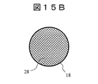
本実施例も、前述した実施例10の場合と同様、図10で説明した最適流速条件の維持を目的とする。ただし、本実施例では、図15A及び図15Bに示すように、複数の開口部を網目状に配置したメッシュ構造の対向電極18を使用する。本実施例の場合、対向電極18のほぼ全面が開口部として使用される。形成される開口部28の総断面積は、対向電極18を構成する線径の太さに依存する。一般に、線径が太いほど総断面積は小さくなる。
Similar to the case of the tenth embodiment described above, this embodiment also aims to maintain the optimum flow velocity condition described in FIG. However, in this embodiment, as shown in FIGS. 15A and 15B, a
なお、対向電極18の総断面積は、APCIイオン源3への最適な流速条件を維持するように設定する。本実施例によれば、実施例9の基本的な効果に加え、ESIイオンの発生強度とAPCIイオンの発生強度を両立することができるハイブリッドイオン源を得ることができる。また、本実施例の対向電極18は、実施例1〜8、10及び11で説明したハイブリッドイオン源1と組み合わせて使用しても良い。
The total cross-sectional area of the
(実施例14)
本実施例では、実施例1に係るハイブリッドイオン源にあって、APCIイオン源3を複数配置する場合について説明する。(Example 14)
In the present embodiment, a case where a plurality of
図16に、本実施例に係るハイブリッドイオン源1の概略構成を示す。図16には図9との対応部分に同一符号を付して示す。ただし、図16は、ESIイオン源2と対向する底面側から上方を見上げる方向についてのハイブリッドイオン源1の断面構造を示している。なお、加熱ガス管37は図示していない。
FIG. 16 shows a schematic configuration of the
図16は、ESIイオン源2と対向する底面側から上方を見上げる方向の断面図であるため、キャピラリー4と噴霧管8の先端部は同心円形状として表されている。また、ESIイオン化室24の断面形状も、キャピラー4と同心円形状として表されている。
FIG. 16 is a cross-sectional view in the direction of looking up from the bottom side facing the
図16の場合、3つのAPCIイオン源3がESIイオン化室24の円周に沿って配置されている。図16では、1つのAPCIイオン源3にだけ配管29及び30を介して排気ポンプ27が接続されているが、残る2つのAPCIイオン源3も同じ構成を有している。
In the case of FIG. 16, three
本実施例の場合、ESIイオン化室24に取り付けられたAPCIイオン源3の数が複数となるため、個々のAPCIイオン源3に導入される試料ガス16の量(流速)を実施例9の場合よりも減らすことができる。この結果、個々のAPCIイオン源3における試料ガス16の流速条件を最適な状態に維持することができる。
In the case of the present embodiment, since the number of
また、各APCIイオン源3におけるAPCIイオンの発生強度も増加するため、他の実施例以上に多くのAPCIイオンをESIイオン化室24内に供給することができる。
In addition, since the generation intensity of APCI ions in each
なお、取り付け上の制約はあるが、各APCIイオン源3は、その開口部から円錐状に放出されるイオン軌道の見込み角又はその近傍範囲に第1細孔電極11のイオン導入口が位置するように配置される。
Although there are restrictions on the mounting, each
本実施例によれば、実施例9の基本的な効果に加え、ESIイオンの発生強度とAPCIイオンの発生強度を両立することができるハイブリッドイオン源を得ることができる。また、本実施例の対向電極18は、実施例1〜8、10〜13で説明したハイブリッドイオン源1と組み合わせて使用しても良い。
According to the present embodiment, in addition to the basic effects of the ninth embodiment, a hybrid ion source that can achieve both the generation intensity of ESI ions and the generation intensity of APCI ions can be obtained. Moreover, you may use the
(実施例15)
本実施例では、実施例1とほぼ同様の構成のハイブリッドイオン源において、各電極に電圧を印加する電源として印加電圧を高速に切り替え可能な電源を使用し、電源の切り替えタイミングに合わせてESIイオン化領域からコロナ放電領域への排気流量などを変化させる機能を追加したハイブリッドイオン源について説明する。(Example 15)
In this embodiment, in a hybrid ion source having a configuration substantially similar to that of the first embodiment, a power source capable of switching the applied voltage at high speed is used as a power source for applying a voltage to each electrode, and ESI ionization is performed in accordance with the power source switching timing. A hybrid ion source having a function of changing the exhaust flow rate from the region to the corona discharge region will be described.
図17に、本実施例に係るハイブリッドイオン源1の概略構成を示す。本実施例におけるハイブリッドイオン源1の基本的な構造は図1と同じである。従って、図17には図1との対応部分に同一符号を付して示し、相違点についてのみ説明する。
FIG. 17 shows a schematic configuration of the
本実施例の場合、電源6、電源13、電源20、電源21は、印加電圧を高速に切り替えることができる機能を有している。なお、電源6はキャピラリー4に電圧を印加し、電源13は第1細孔電極11に電圧を印加し、電源20は針電極17に電圧を印加し、電源21は対向電極18に電圧を印加する。これら電源等の電圧の切替制御は、不図示の制御部45が実行する。
In the case of the present embodiment, the
図18に、制御部45の機能構成と、各機能部と制御対象との接続関係を示す。制御部45は、電圧制御部46とガス流量制御部47とで構成される。電圧制御部46は、電源6、電源13、電源20、電源21による印加電圧を制御する。ガス流量制御部47は、排気ポンプ27と流量調節機構31の動作を制御する。
FIG. 18 illustrates a functional configuration of the
前述したように、ESIイオン源2とAPCIイオン源3は、いずれも正イオンと負イオンを生成することができる。ただし、各電極類に印加する電圧条件は、生成するイオンの極性に応じて異なっている。基本的に、正イオンを生成する場合にはプラスの電圧が各電極類に印加され、負イオンを生成する場合にはマイナスの電圧が各電極類に印加される。もっとも、電圧の印加条件は、これに限らない。
As described above, both the
従って、連続的に流れてくる試料溶液5を正負両方のイオン化モードでイオン化したい場合、各電源を高速に切り替える必要がある。
Therefore, when it is desired to ionize the
また、前述した実施例に係るハイブリッドイオン源1では、ESIイオン化領域23からコロナ放電領域19の方向への気流26が存在する状態でAPCIイオンを生成しているが、生成するイオンが正イオンか負イオンかに応じて最適流速条件が異なる場合が考えられる。つまり、正イオンと負イオンに応じ、流速を切り替える場合が考えられる。
Further, in the
そこで、制御部45は、各電源の切り替えタイミングに合わせて、排気ポンプ27と流量調節機構31の動きを制御し、最適な流速条件が満たされるようにする。この結果、正負のモード切り替えによるイオン強度の低下を防ぐことができる。
Therefore, the
なお、図9、図11、図12、図14、図16に示すような電極39を有する場合は、この電極に印加する電圧も切り替え制御する必要がある。さらに、他の電極類を有する場合やイオンを分析する質量分析計などの内部の電極類なども当然のように、印加電圧を切り替え制御する必要がある。このため、図18では、これらの電源類をまとめて電源48として図示している。
In the case where the
また、図11に示すようにESIイオン化室24を排気ポンプ41で直接排気する場合や流量調節機構44を設ける場合には、排気ポンプ41や流量調節機構44も同時に制御しても良い。
As shown in FIG. 11, when the
本実施例によれば、実施例1の基本的な効果に加え、イオン化モードの切り替えに応じた印加電圧や流速条件の最適化を実現することができる。なお、本実施例の装置構成は、前述した実施例1〜14と組み合わせて使用することが可能である。
According to the present embodiment, in addition to the basic effects of the first embodiment, it is possible to realize optimization of the applied voltage and flow rate conditions according to switching of the ionization mode. In addition, the apparatus configuration of the present embodiment can be used in combination with the above-described
(実施例16)
本実施例では、実施例1とほぼ同様の構成のハイブリッドイオン源に対し、APCIイオン源に有機溶媒を導入する配管を追加したハイブリッドイオン源について説明する。(Example 16)
In this embodiment, a hybrid ion source will be described in which a pipe for introducing an organic solvent into the APCI ion source is added to the hybrid ion source having substantially the same configuration as that of the first embodiment.
図19に、本実施例に係るハイブリッドイオン源1の概略構成を示す。本実施例におけるハイブリッドイオン源1の基本的な構造は図1に示す構造と同じである。従って、図19には図1との対応部分に同一符号を付して示す。以下では、実施例1との相違点のみを説明する。
FIG. 19 shows a schematic configuration of the
本実施例では、APCIイオン源3の内部に形成されるコロナ放電領域19に向けて配管51を取り付ける構成を採用する。配管51の外周には加熱部49が配置されており、この加熱部49により配管51に導入された有機溶媒50は加熱され気化される。気化された有機溶媒50は、ガスとしてコロナ放電領域19に導入される。
In the present embodiment, a configuration in which the
このような構造を採用する理由は、有機溶媒と水などを混合した試料溶液5をESIイオン源2に導入する場合があるためである。水を含んだ有機溶媒を使用した場合、APCIイオン源3における一次イオンの生成効率が低下する場合がある。そこで、本実施例では、図19に示すように、配管51を通じて有機溶媒50から生成したガスをAPCIイオン源3の中に直接導入する。これにより、コロナ放電領域19における有機溶媒の濃度を高め(水などの濃度を低下させ)、一次イオンを多量に生成できるようにする。この結果、APCIイオンの生成効率を向上することができる。
The reason why such a structure is adopted is that a
なお、加熱部49には、ヒートブロックのように配管51に直接接触した状態で加熱する方式、ランプや赤外線による加熱のように配管51に非接触な状態で加熱する方式など、様々な方式を用いることができる。
The
本実施例によれば、前述したように試料溶液5として有機溶媒と水などの混合液を使用する場合にも、APCIイオンの生成効率の高いハイブリッドイオン源1を提供することができる。なお、本実施例の構成は、前述した実施例1〜15の構成と組み合わせて使用することができる。
According to the present embodiment, as described above, the
(実施例17)
本実施例では、実施例1に係るハイブリッドイオン源を使用した質量分析計について説明する。(Example 17)
In this example, a mass spectrometer using the hybrid ion source according to Example 1 will be described.
図20に、本実施例に係る質量分析計の構成例を示す。図20に示す質量分析計のうちハイブリッドイオン源1の構成は図1と同様である。従って、図20には図1との対応部分に同一符号を付して示している。以下では、実施例1との差異点についてのみ説明する。
FIG. 20 shows a configuration example of the mass spectrometer according to the present embodiment. The configuration of the
本実施例における質量分析計は、第1細孔電極11の一端側に質量分析/検出部52を結合した構成を有している。このため、質量分析/検出部52には、ハイブリッドイオン源1で生成されたESIイオン7とAPCIイオンの両方が同時に導入される。質量分析/検出部52は、導入されたイオンの分離・解離などの工程を経て詳細な質量や構造を解析する。この結果、一度の測定により、高精度かつ短時間にて質量分析を実行することができる。なお、解析処理は不図示のデータ処理部(計算機)で実行される。
The mass spectrometer in the present embodiment has a configuration in which a mass spectrometer /
因みに、質量分析には、四重極質量分析方式、イオントラップ方式、飛行型質量分析方式など様々な方式を用いることができる。なお、これらの方式を組み合わせて使用することもできる。 Incidentally, various methods such as a quadrupole mass analysis method, an ion trap method, and a flight mass analysis method can be used for mass analysis. These methods can be used in combination.
本実施例では、実施例1に係るハイブリッドイオン源1を使用したが、実施例2〜16に係るハイブリッドイオン源1と質量分析/検出部52を組み合わせて質量分析計を構成しても良い。
In this embodiment, the
(実施例18)
本実施例では、実施例1に係るハイブリッドイオン源を使用して構成したイオンモビリティ装置について説明する。(Example 18)
In the present embodiment, an ion mobility apparatus configured using the hybrid ion source according to the first embodiment will be described.
図21に、本実施例に係るイオンモビリティ装置の構成例を示す。図21に示すイオンモビリティ装置のうちハイブリッドイオン源1の構成は図1と同様である。従って、図21には図1との対応部分に同一符号を付して示している。以下では、実施例1との差異点についてのみ説明する。
FIG. 21 shows a configuration example of the ion mobility device according to the present embodiment. The configuration of the
本実施例におけるイオンモビリティ装置は、第1細孔電極11の一端側にイオンモビリティ部53を結合した構成を有している。このため、イオンモビリティ部53には、ハイブリッドイオン源1で生成されたESIイオン7とAPCIイオンの両方が同時に導入される。イオンモビリティ部53は、導入されたイオンの構造の違いによる移動度の違いに基づいてイオンを分離し解析する。
The ion mobility apparatus in the present embodiment has a configuration in which an
イオンモビリティ部53には、ドリフトチューブ方式、平行平板方式など様々な方式を用いることができる。また、これらの方式を組み合わせて使用することもできる。なお、本実施例におけるイオンモビリティ部53を前述した質量分析/検出部52と組み合わせて使用することもできる。
Various systems such as a drift tube system and a parallel plate system can be used for the
本実施例では、実施例1に係るハイブリッドイオン源1を使用したが、実施例2〜16に係るハイブリッドイオン源1とイオンモビリティ部53を組み合わせてイオンモビリティ装置を構成しても良い。
In the present embodiment, the
(実施例19)
本実施例では、ハイブリッドイオン源を構成する他の構成例を説明する。前述の実施例では、ESIイオン源2とAPCIイオン源3を有するハイブリッドイオン源について説明したが、本実施例では、主に溶液試料などをイオン化する第1のイオン源と、主に気体などのガス試料をイオン化する第2のイオン源とで構成されるハイブリッドイオン源について説明する。(Example 19)
In the present embodiment, another configuration example constituting the hybrid ion source will be described. In the above-described embodiment, the hybrid ion source having the
図22に、本実施例に係るハイブリッドイオン源1の概略構成を示す。なお、本実施例におけるハイブリッドイオン源1の基本的な構成は図1に示す配置構造とほぼ同じである。従って、図22には図1との対応部分に同一符号を付して示す。以下では、実施例1との相違点についてのみ説明する。
FIG. 22 shows a schematic configuration of the
本実施例では、主に溶液試料などをイオン化する第1のイオン源54と、主に気体などのガス試料をイオン化する第2のイオン源55とをチャンバに取り付けた構造を有している。本実施例の場合も、第1のイオン源54はチャンバの天井面に取り付けられ、第2のイオン源55は第1細孔電極11と対向するようにチャンバの側壁面に取り付けられている。
This embodiment has a structure in which a
第1のイオン源54には、ESIイオン源2を使用することも可能であるが、例えばサーモスプレーイオン化(TSP)、ソニックスプレーイオン化(SSI)、コールドスプレーイオン化(CSI)、レーザースプレーイオン化(LSI)、脱離エレクトロスプレーイオン化(DESI)など、様々なイオン化方式を使用することができる。
The
第2のイオン源55には、APCIイオン源3を使用することも可能であるが、例えば大気圧光イオン化(APPI)、誘電体バリア放電イオン化(DBD)など、様々なイオン化方式を使用することができる。
The
なお、前述した第1のイオン源54や第2のイオン源55に適用可能なイオン化方式はあくまでも一例であり、その他の多種多様なイオン化方式も使用することができる。
The ionization method applicable to the
本実施例では、第1のイオン源54によってイオンが生成される第1のイオン化領域56と、第2のイオン源55によってイオンが生成される第2のイオン化領域57は、開口部58を有する電極59により物理的に区切られている。
In this embodiment, the
また、本実施例の場合も、主にガス試料をイオン化する第2のイオン源55に排気ポンプ27を接続し、第1のイオン化領域56から第2のイオン化領域57の方向に気流26を生成する構造を採用する。これにより、第1のイオン化領域56で生成された試料ガス16などを効率良く第2のイオン化領域57に導入することができる。この結果、第2のイオン源55において生成されるイオンの強度を向上させることができる。
Also in the present embodiment, the
また、本実施例の場合、電極59の電位は、電源21から印加される電位に設定されている。このため、第1のイオン源54に発生する電界の第2のイオン化領域57への影響だけでなく、第2のイオン源55に発生する電界の第1のイオン化領域56への影響も抑制することができる。結果的に、第1のイオン源54と第2のイオン源55は、互いに他方のイオン源で発生されるイオンの強度低下を防ぐことができる。
In the present embodiment, the potential of the
なお、第1のイオン源54で生成されたイオン60は、例えば矢印61に示す軌道を通り、第1細孔電極11の開口部12に導入される。また、第2のイオン源55で生成されたイオンは、例えば矢印62に示す軌道を通り、第1細孔電極11の開口部12に導入される。
In addition, the
本実施例に係る装置構成は、前述した実施例1〜18における装置構成と組み合わせて使用することも可能である。
The apparatus configuration according to the present embodiment can also be used in combination with the apparatus configurations according to the above-described
(他の実施例)
本発明は上述した実施例に限定されるものでなく、様々な変形を含んでいる。例えば、上述した実施例は、本発明を分かりやすく説明するために詳細に説明したものであり、必ずしも説明した全ての構成を備える構成に限定されない。また、ある実施例の一部を、他の実施例の構成に置き換えることが可能である。また、ある実施例の構成に、他の実施例の構成を加えることも可能である。また、各実施例の構成の一部について、他の構成を追加、削除又は置換することも可能である。なお、本明細書中で説明している排気手段としてのポンプについては、気流を発生させるものであればよく、ポンプの他にファン等を用いることができることは明らかである。(Other examples)
The present invention is not limited to the above-described embodiments, and includes various modifications. For example, the above-described embodiments have been described in detail for easy understanding of the present invention, and are not necessarily limited to the configurations including all the configurations described. Moreover, it is possible to replace a part of a certain Example with the structure of another Example. Moreover, it is also possible to add the structure of another Example to the structure of a certain Example. Moreover, it is also possible to add, delete, or replace another configuration for a part of the configuration of each embodiment. In addition, about the pump as an exhaust means currently demonstrated in this specification, what is necessary is just to generate an airflow, and it is clear that a fan etc. can be used besides a pump.
また、制御線や情報線は、説明上必要と考えられるものを示すものであり、製品上必要な全ての制御線や情報線を表すものでない。実際にはほとんど全ての構成が相互に接続されていると考えて良い。 Control lines and information lines indicate what is considered necessary for the description, and do not represent all control lines and information lines necessary for the product. In practice, it can be considered that almost all components are connected to each other.
1…イオン源
2…ESIイオン源
3…APCIイオン源
4…キャピラリー
5…試料溶液
6…電源
7…ESIイオン
8…噴霧管
9…噴霧ガス
11…第1細孔電極
12…開口部
13…電源
14…液滴
16…試料ガス
17…針電極
18…対向電極
19…コロナ放電領域
20…電源
21…電源
23…ESIイオン化領域
24…ESIイオン化室
25…コロナ放電室
26…気流
27…排気ポンプ
28…開口部
29…配管
30…配管
31…流量調節機構
32…加熱部
33…加熱部
34…加熱部
35…加熱部
37…加熱ガス管
38…加熱ガス
39…電極
40…ガス
41…排気ポンプ
42…配管
43…配管
44…流量調節機構
45…制御部
46…電圧制御部
47…ガス流量制御部
48…電源
49…加熱部
50…有機溶媒
51…配管
52…質量分析/検出計
53…イオンモビリティ部
54…第1のイオン源
55…第2のイオン源
56…第1のイオン化領域
57…第2のイオン化領域
58…開口部
59…電極
60…イオンDESCRIPTION OF
Claims (14)
試料溶液を前記チャンバ内に噴霧してイオン化する第1のイオン源と、
前記第1のイオン源から噴霧された液滴やガス成分を前記チャンバから導入してイオン化する第2のイオン源と、
前記第1のイオン源により生成された第1のイオンと前記第2のイオン源により生成された第2のイオンを前記チャンバ内から導入する第1の電極と、
前記第1のイオンが生成される前記チャンバ内の第1の空間領域から前記第2のイオンが生成される前記第2のイオン源内の第2の空間領域の方向に気流を発生する排気手段と
を有するハイブリッドイオン源。 A chamber;
A first ion source that sprays and ionizes a sample solution into the chamber ;
A second ion source for introducing and ionizing droplets and gas components sprayed from the first ion source from the chamber ;
A first electrode for introducing a first ion generated by the first ion source and a second ion generated by the second ion source from within the chamber ;
Exhaust means for generating an air flow in a direction from the first space region in the chamber in which the first ions are generated to the second space region in the second ion source in which the second ions are generated; A hybrid ion source.
前記第1のイオン源は、前記試料溶液を噴霧するキャピラリー電極を有し、
前記第2のイオン源は、針電極と、前記針電極と対向した位置にある対向電極とを有し、
前記対向電極と前記キャピラリー電極との間の電界強度が、前記第1の電極と前記キャピラリー電極との間の電界強度よりも小さい
ことを特徴とするハイブリッドイオン源。 The hybrid ion source of claim 1,
The first ion source has a capillary electrode for spraying the sample solution,
The second ion source has a needle electrode and a counter electrode at a position facing the needle electrode,
The hybrid ion source, wherein an electric field strength between the counter electrode and the capillary electrode is smaller than an electric field strength between the first electrode and the capillary electrode.
前記第1の空間領域を加熱する加熱部を有する
ことを特徴とするハイブリッドイオン源。 The hybrid ion source of claim 1,
A hybrid ion source comprising a heating section for heating the first space region.
前記第2の空間領域を加熱する加熱部を有する
ことを特徴とするハイブリッドイオン源。 The hybrid ion source of claim 1,
A hybrid ion source comprising a heating section for heating the second space region.
前記第2のイオン源は、針電極と、前記針電極と対向した位置にある対向電極と、前記針電極を加熱する加熱部とを有する
ことを特徴とするハイブリッドイオン源。 The hybrid ion source of claim 1,
The second ion source includes a needle electrode, a counter electrode at a position facing the needle electrode, and a heating unit that heats the needle electrode.
前記第1のイオン源は、前記試料溶液を噴霧するキャピラリー電極を有し、
前記キャピラリー電極と対向する位置に配置され、少なくとも前記キャピラリー電極から噴霧された液滴を加熱する加熱部を有する
ことを特徴とするハイブリッドイオン源。 The hybrid ion source of claim 1,
The first ion source has a capillary electrode for spraying the sample solution,
A hybrid ion source comprising: a heating unit that is disposed at a position facing the capillary electrode and that heats at least droplets sprayed from the capillary electrode.
前記チャンバに接続され、チャンバ内を排気する第2の排気手段を有する
ことを特徴とするハイブリッドイオン源。 The hybrid ion source of claim 1,
A hybrid ion source comprising: a second exhaust unit connected to the chamber and exhausting the inside of the chamber.
前記対向電極は、複数の開口部を有する
ことを特徴とするハイブリッドイオン源。 The hybrid ion source according to claim 5,
The counter electrode has a plurality of openings. A hybrid ion source, wherein:
前記第2のイオン源を複数有する
ことを特徴とするハイブリッドイオン源。 The hybrid ion source of claim 1,
A hybrid ion source comprising a plurality of the second ion sources.
前記第1のイオン源は、前記試料溶液を噴霧するキャピラリー電極を有し、さらに、
前記キャピラリー電極に電圧を印加する第1の電源及び/又は前記第2のイオン源内の針電極に電圧を印加する第2の電源と、
前記第1及び第2の電源のうち少なくとも一方における印加電圧を切り替えるタイミングに同期して、前記排気手段の排気流量値を切り替え制御する制御部とを有する
ことを特徴とするハイブリッドイオン源。 The hybrid ion source of claim 1,
The first ion source has a capillary electrode for spraying the sample solution, and
A first power source for applying a voltage to the capillary electrode and / or a second power source for applying a voltage to a needle electrode in the second ion source;
A hybrid ion source comprising: a control unit that switches and controls an exhaust flow value of the exhaust means in synchronization with a timing of switching an applied voltage in at least one of the first and second power supplies.
前記第2の空間領域に溶媒を導入する配管を有する
ことを特徴とするハイブリッドイオン源。 The hybrid ion source of claim 1,
A hybrid ion source comprising a pipe for introducing a solvent into the second space region.
前記第1のイオン源はESIイオン源であり、
前記第2のイオン源はAPCIイオン源である
ことを特徴とするハイブリッドイオン源。 The hybrid ion source of claim 1,
The first ion source is an ESI ion source;
The hybrid ion source, wherein the second ion source is an APCI ion source.
前記第1の電極よりイオンを導入する質量分析/検出部と
を有する質量分析装置。 A hybrid ion source according to claim 1;
A mass spectrometer having a mass spectrometer / detector for introducing ions from the first electrode.
前記第1の電極よりイオンを導入するイオンモビリティ部と
を有するイオンモビリティ装置。 A hybrid ion source according to claim 1;
An ion mobility device comprising: an ion mobility unit that introduces ions from the first electrode.
Priority Applications (1)
| Application Number | Priority Date | Filing Date | Title |
|---|---|---|---|
| JP2014550104A JP5893756B2 (en) | 2012-11-29 | 2013-11-07 | Hybrid ion source, mass spectrometer and ion mobility device |
Applications Claiming Priority (4)
| Application Number | Priority Date | Filing Date | Title |
|---|---|---|---|
| JP2012261212 | 2012-11-29 | ||
| JP2012261212 | 2012-11-29 | ||
| JP2014550104A JP5893756B2 (en) | 2012-11-29 | 2013-11-07 | Hybrid ion source, mass spectrometer and ion mobility device |
| PCT/JP2013/080111 WO2014084015A1 (en) | 2012-11-29 | 2013-11-07 | Hybrid ion source, mass spectrometer, and ion mobility device |
Publications (2)
| Publication Number | Publication Date |
|---|---|
| JP5893756B2 true JP5893756B2 (en) | 2016-03-23 |
| JPWO2014084015A1 JPWO2014084015A1 (en) | 2017-01-05 |
Family
ID=50827661
Family Applications (1)
| Application Number | Title | Priority Date | Filing Date |
|---|---|---|---|
| JP2014550104A Active JP5893756B2 (en) | 2012-11-29 | 2013-11-07 | Hybrid ion source, mass spectrometer and ion mobility device |
Country Status (4)
| Country | Link |
|---|---|
| US (1) | US9852897B2 (en) |
| EP (1) | EP2927930B8 (en) |
| JP (1) | JP5893756B2 (en) |
| WO (1) | WO2014084015A1 (en) |
Families Citing this family (17)
| Publication number | Priority date | Publication date | Assignee | Title |
|---|---|---|---|---|
| DE102013218930A1 (en) * | 2013-09-20 | 2015-04-16 | Lubrisense Gmbh | Multiple oil emission meter for engines |
| JP6666011B2 (en) * | 2015-07-23 | 2020-03-13 | 国立研究開発法人産業技術総合研究所 | Apparatus and method for producing metal nanoparticle dispersion, method for producing metal nanoparticle carrier, metal nanoparticle, metal nanoparticle dispersion, metal nanoparticle carrier |
| WO2017103743A1 (en) * | 2015-12-18 | 2017-06-22 | Dh Technologies Development Pte. Ltd. | System for minimizing electrical discharge during esi operation |
| CN105632872B (en) * | 2016-03-11 | 2017-09-05 | 北京理工大学 | A kind of ion mobility spectrometry apparatus based on corona discharge |
| JP6926544B2 (en) * | 2016-08-05 | 2021-08-25 | 株式会社リコー | Cleaning air creation device and measurement system |
| WO2018078693A1 (en) * | 2016-10-24 | 2018-05-03 | 株式会社島津製作所 | Mass spectrometry device and ion detection device |
| WO2018100612A1 (en) * | 2016-11-29 | 2018-06-07 | 株式会社島津製作所 | Ionizer and mass spectrometer |
| US20190019662A1 (en) * | 2017-07-14 | 2019-01-17 | Purdue Research Foundation | Electrophoretic mass spectrometry probes and systems and uses thereof |
| CN108364848A (en) * | 2017-12-31 | 2018-08-03 | 宁波大学 | Portable ion source and its working method |
| CN109187711B (en) * | 2018-09-19 | 2024-01-19 | 东华理工大学 | Enclosed electrospray extraction ionization source device |
| EP3998624A4 (en) * | 2019-07-10 | 2023-03-29 | Hitachi High-Tech Corporation | MASS SPECTROMETER |
| EP4113578A4 (en) * | 2020-02-25 | 2024-03-20 | Biochromato, Inc. | IONIZATION DEVICE, MASS SPECTROSCOPY SYSTEM AND IONIZATION METHOD |
| FI20206161A1 (en) | 2020-11-17 | 2022-05-18 | Karsa Oy | Unbiased ion identification by multiple ions |
| JP7657089B2 (en) * | 2021-04-05 | 2025-04-04 | 株式会社日立ハイテク | Mass spectrometer and control method thereof |
| DE102021204046A1 (en) | 2021-04-22 | 2022-10-27 | Carl Zeiss Smt Gmbh | Device for the spectrometric analysis of a gas and lithography system |
| US11621155B2 (en) * | 2021-07-29 | 2023-04-04 | Bayspec, Inc. | Multi-modal ionization for mass spectrometry |
| CN118136489B (en) * | 2024-05-07 | 2024-07-19 | 上海奥浦迈生物科技股份有限公司 | Mixed gas device of acid gas and inert gas and application thereof |
Citations (1)
| Publication number | Priority date | Publication date | Assignee | Title |
|---|---|---|---|---|
| WO2007032088A1 (en) * | 2005-09-16 | 2007-03-22 | Shimadzu Corporation | Mass analyzer |
Family Cites Families (15)
| Publication number | Priority date | Publication date | Assignee | Title |
|---|---|---|---|---|
| JP3274302B2 (en) * | 1994-11-28 | 2002-04-15 | 株式会社日立製作所 | Mass spectrometer |
| US6960761B2 (en) * | 1997-06-02 | 2005-11-01 | Advanced Research & Technology Institute | Instrument for separating ions in time as functions of preselected ion mobility and ion mass |
| DE60044892D1 (en) * | 1999-09-20 | 2010-10-14 | Hitachi Ltd | Ion source, mass spectrometer, mass spectrometry and monitoring system |
| JP4416259B2 (en) * | 2000-03-24 | 2010-02-17 | キヤノンアネルバ株式会社 | Mass spectrometer |
| JP3660279B2 (en) * | 2001-07-23 | 2005-06-15 | 株式会社日立製作所 | Sample ionizer and mass spectrometer |
| US7078681B2 (en) * | 2002-09-18 | 2006-07-18 | Agilent Technologies, Inc. | Multimode ionization source |
| JP3787549B2 (en) * | 2002-10-25 | 2006-06-21 | 株式会社日立ハイテクノロジーズ | Mass spectrometer and mass spectrometry method |
| JP4337584B2 (en) * | 2004-03-10 | 2009-09-30 | 株式会社日立製作所 | Mass spectrometer and ion source |
| ITMI20041523A1 (en) * | 2004-07-27 | 2004-10-27 | Getters Spa | IONIC MOBILITY SPECTROMETER INCLUDING A DISCHARGE IONIZING ELEMENT IN CROWN |
| US7034291B1 (en) * | 2004-10-22 | 2006-04-25 | Agilent Technologies, Inc. | Multimode ionization mode separator |
| US20060255261A1 (en) * | 2005-04-04 | 2006-11-16 | Craig Whitehouse | Atmospheric pressure ion source for mass spectrometry |
| US20070023677A1 (en) | 2005-06-29 | 2007-02-01 | Perkins Patrick D | Multimode ionization source and method for screening molecules |
| US7411186B2 (en) * | 2005-12-20 | 2008-08-12 | Agilent Technologies, Inc. | Multimode ion source with improved ionization |
| CN202172060U (en) * | 2008-05-30 | 2012-03-21 | 珀金埃尔默健康科学股份有限公司 | Apparatus used for ionization chemical species |
| US8759757B2 (en) * | 2010-10-29 | 2014-06-24 | Thermo Finnigan Llc | Interchangeable ion source for electrospray and atmospheric pressure chemical ionization |
-
2013
- 2013-11-07 US US14/442,199 patent/US9852897B2/en active Active
- 2013-11-07 JP JP2014550104A patent/JP5893756B2/en active Active
- 2013-11-07 EP EP13858963.5A patent/EP2927930B8/en active Active
- 2013-11-07 WO PCT/JP2013/080111 patent/WO2014084015A1/en not_active Ceased
Patent Citations (1)
| Publication number | Priority date | Publication date | Assignee | Title |
|---|---|---|---|---|
| WO2007032088A1 (en) * | 2005-09-16 | 2007-03-22 | Shimadzu Corporation | Mass analyzer |
Also Published As
| Publication number | Publication date |
|---|---|
| EP2927930B8 (en) | 2019-08-21 |
| JPWO2014084015A1 (en) | 2017-01-05 |
| WO2014084015A1 (en) | 2014-06-05 |
| US9852897B2 (en) | 2017-12-26 |
| EP2927930B1 (en) | 2019-07-17 |
| EP2927930A1 (en) | 2015-10-07 |
| EP2927930A4 (en) | 2016-07-20 |
| US20160300703A1 (en) | 2016-10-13 |
Similar Documents
| Publication | Publication Date | Title |
|---|---|---|
| JP5893756B2 (en) | Hybrid ion source, mass spectrometer and ion mobility device | |
| CN103597574B (en) | By high velocity fog and the synergistic atmospheric pressure ionizationion of target | |
| JP3079055B2 (en) | Electrospray, atmospheric pressure chemical ionization mass spectrometer and ion source | |
| Ebeling et al. | Corona discharge in charge reduction electrospray mass spectrometry | |
| JP5106616B2 (en) | Multimode ionization source, method of generating ions using the same, and multimode ionization mass spectrometer | |
| JP6320933B2 (en) | Impact ion generator and separator | |
| US7002146B2 (en) | Ion sampling for APPI mass spectrometry | |
| US10546740B2 (en) | Mass spectrometry device and ion detection device | |
| CN100517555C (en) | Multimode ionization mode separator | |
| US6462336B1 (en) | Ion source for a mass analyzer and method of providing a source of ions for analysis | |
| EP2793248A2 (en) | Multimode ionization device | |
| CN104040680B (en) | Quality analysis apparatus | |
| CN103959428B (en) | For applying the system and method for heavy curtain air-flow in a mass spectrometer | |
| US10684256B2 (en) | Analysis device provided with ion mobility separation part | |
| JP2011113832A (en) | Mass spectrometer | |
| CN112750679B (en) | Mass spectrometry system and method | |
| JP4839276B2 (en) | Liquid chromatograph mass spectrometer | |
| JP2002056801A (en) | Ion source and mass spectrometer using the same | |
| JP2000227417A (en) | Mass spectrometry method and apparatus | |
| JP2003331777A (en) | Mass spectrometer | |
| HK1193497B (en) | Atmospheric pressure ion source by interacting high velocity spray with a target |
Legal Events
| Date | Code | Title | Description |
|---|---|---|---|
| A131 | Notification of reasons for refusal |
Free format text: JAPANESE INTERMEDIATE CODE: A131 Effective date: 20151215 |
|
| A521 | Request for written amendment filed |
Free format text: JAPANESE INTERMEDIATE CODE: A523 Effective date: 20160112 |
|
| TRDD | Decision of grant or rejection written | ||
| A01 | Written decision to grant a patent or to grant a registration (utility model) |
Free format text: JAPANESE INTERMEDIATE CODE: A01 Effective date: 20160209 |
|
| A61 | First payment of annual fees (during grant procedure) |
Free format text: JAPANESE INTERMEDIATE CODE: A61 Effective date: 20160224 |
|
| R150 | Certificate of patent or registration of utility model |
Ref document number: 5893756 Country of ref document: JP Free format text: JAPANESE INTERMEDIATE CODE: R150 |
|
| S531 | Written request for registration of change of domicile |
Free format text: JAPANESE INTERMEDIATE CODE: R313531 |
|
| S533 | Written request for registration of change of name |
Free format text: JAPANESE INTERMEDIATE CODE: R313533 |
|
| R350 | Written notification of registration of transfer |
Free format text: JAPANESE INTERMEDIATE CODE: R350 |