JP5872828B2 - Light emitting module and phosphor - Google Patents
Light emitting module and phosphor Download PDFInfo
- Publication number
- JP5872828B2 JP5872828B2 JP2011213411A JP2011213411A JP5872828B2 JP 5872828 B2 JP5872828 B2 JP 5872828B2 JP 2011213411 A JP2011213411 A JP 2011213411A JP 2011213411 A JP2011213411 A JP 2011213411A JP 5872828 B2 JP5872828 B2 JP 5872828B2
- Authority
- JP
- Japan
- Prior art keywords
- light
- light emitting
- phosphor
- emitting module
- blue
- Prior art date
- Legal status (The legal status is an assumption and is not a legal conclusion. Google has not performed a legal analysis and makes no representation as to the accuracy of the status listed.)
- Expired - Fee Related
Links
Images


Classifications
-
- H—ELECTRICITY
- H10—SEMICONDUCTOR DEVICES; ELECTRIC SOLID-STATE DEVICES NOT OTHERWISE PROVIDED FOR
- H10H—INORGANIC LIGHT-EMITTING SEMICONDUCTOR DEVICES HAVING POTENTIAL BARRIERS
- H10H20/00—Individual inorganic light-emitting semiconductor devices having potential barriers, e.g. light-emitting diodes [LED]
- H10H20/80—Constructional details
- H10H20/85—Packages
- H10H20/851—Wavelength conversion means
- H10H20/8511—Wavelength conversion means characterised by their material, e.g. binder
- H10H20/8512—Wavelength conversion materials
-
- C—CHEMISTRY; METALLURGY
- C09—DYES; PAINTS; POLISHES; NATURAL RESINS; ADHESIVES; COMPOSITIONS NOT OTHERWISE PROVIDED FOR; APPLICATIONS OF MATERIALS NOT OTHERWISE PROVIDED FOR
- C09K—MATERIALS FOR MISCELLANEOUS APPLICATIONS, NOT PROVIDED FOR ELSEWHERE
- C09K11/00—Luminescent, e.g. electroluminescent, chemiluminescent materials
- C09K11/08—Luminescent, e.g. electroluminescent, chemiluminescent materials containing inorganic luminescent materials
- C09K11/77—Luminescent, e.g. electroluminescent, chemiluminescent materials containing inorganic luminescent materials containing rare earth metals
- C09K11/7728—Luminescent, e.g. electroluminescent, chemiluminescent materials containing inorganic luminescent materials containing rare earth metals containing europium
- C09K11/7737—Phosphates
- C09K11/7738—Phosphates with alkaline earth metals
- C09K11/7739—Phosphates with alkaline earth metals with halogens
-
- H—ELECTRICITY
- H10—SEMICONDUCTOR DEVICES; ELECTRIC SOLID-STATE DEVICES NOT OTHERWISE PROVIDED FOR
- H10H—INORGANIC LIGHT-EMITTING SEMICONDUCTOR DEVICES HAVING POTENTIAL BARRIERS
- H10H20/00—Individual inorganic light-emitting semiconductor devices having potential barriers, e.g. light-emitting diodes [LED]
- H10H20/80—Constructional details
- H10H20/81—Bodies
- H10H20/822—Materials of the light-emitting regions
- H10H20/824—Materials of the light-emitting regions comprising only Group III-V materials, e.g. GaP
- H10H20/825—Materials of the light-emitting regions comprising only Group III-V materials, e.g. GaP containing nitrogen, e.g. GaN
-
- H—ELECTRICITY
- H10—SEMICONDUCTOR DEVICES; ELECTRIC SOLID-STATE DEVICES NOT OTHERWISE PROVIDED FOR
- H10H—INORGANIC LIGHT-EMITTING SEMICONDUCTOR DEVICES HAVING POTENTIAL BARRIERS
- H10H20/00—Individual inorganic light-emitting semiconductor devices having potential barriers, e.g. light-emitting diodes [LED]
- H10H20/80—Constructional details
- H10H20/85—Packages
- H10H20/851—Wavelength conversion means
- H10H20/8511—Wavelength conversion means characterised by their material, e.g. binder
- H10H20/8512—Wavelength conversion materials
- H10H20/8513—Wavelength conversion materials having two or more wavelength conversion materials
-
- H—ELECTRICITY
- H10—SEMICONDUCTOR DEVICES; ELECTRIC SOLID-STATE DEVICES NOT OTHERWISE PROVIDED FOR
- H10H—INORGANIC LIGHT-EMITTING SEMICONDUCTOR DEVICES HAVING POTENTIAL BARRIERS
- H10H20/00—Individual inorganic light-emitting semiconductor devices having potential barriers, e.g. light-emitting diodes [LED]
- H10H20/80—Constructional details
- H10H20/85—Packages
- H10H20/851—Wavelength conversion means
- H10H20/8514—Wavelength conversion means characterised by their shape, e.g. plate or foil
-
- H—ELECTRICITY
- H10—SEMICONDUCTOR DEVICES; ELECTRIC SOLID-STATE DEVICES NOT OTHERWISE PROVIDED FOR
- H10H—INORGANIC LIGHT-EMITTING SEMICONDUCTOR DEVICES HAVING POTENTIAL BARRIERS
- H10H20/00—Individual inorganic light-emitting semiconductor devices having potential barriers, e.g. light-emitting diodes [LED]
- H10H20/80—Constructional details
- H10H20/85—Packages
- H10H20/851—Wavelength conversion means
- H10H20/8515—Wavelength conversion means not being in contact with the bodies
Landscapes
- Chemical & Material Sciences (AREA)
- Inorganic Chemistry (AREA)
- Engineering & Computer Science (AREA)
- Materials Engineering (AREA)
- Organic Chemistry (AREA)
- Luminescent Compositions (AREA)
- Led Device Packages (AREA)
Description
本発明は、青色発光する蛍光体およびそれを用いた発光モジュールに関する。 The present invention relates to a phosphor emitting blue light and a light emitting module using the same.
従来、照明用の灯具としては蛍光灯や電球が多く用いられてきた。近年、このような灯具の代替として、消費電力や寿命の観点から発光ダイオード(以下、適宜「LED」と称する。)を用いた発光装置が種々開発されている。 Conventionally, fluorescent lamps and light bulbs have been often used as lighting fixtures. In recent years, various light-emitting devices using light-emitting diodes (hereinafter referred to as “LEDs” as appropriate) have been developed as alternatives to such lamps from the viewpoint of power consumption and lifetime.
このような発光装置として、近紫外線を発する半導体発光素子と、青色蛍光体および黄色蛍光体とを組み合わせて白色光を実現する技術が考案されている。例えば、350〜415nmの光を発生する第1の発光体と、第1の発光体からの光の照射によって可視光を発生する第2の発光体とを有する発光装置において、第2の発光体が、一般式EuaCabM5−a−b(PO4)cXd(MはEu及びCa以外の金属元素を表し、XはPO4以外の一価のアニオン基を表す。)の化学組成を有する発光装置が知られている(特許文献1参照)。 As such a light-emitting device, a technology has been devised that realizes white light by combining a semiconductor light-emitting element that emits near-ultraviolet light, a blue phosphor, and a yellow phosphor. For example, in a light-emitting device that includes a first light emitter that generates light of 350 to 415 nm and a second light emitter that generates visible light by irradiation of light from the first light emitter, the second light emitter but the general formula Eu a Ca b M 5-a -b (PO 4) c X d (M represents a metal element other than Eu and Ca, X represents. an anionic group of monovalent non-PO 4) of A light emitting device having a chemical composition is known (see Patent Document 1).
ところで、近年、照明用の灯具として自動車のヘッドランプにLEDを採用する技術が開発されている。また、ヘッドランプでは、コストの低減からLEDの数を減らすことが求められており、LED1個あたりの出力が増大する傾向にある。そのため、このような高出力のLEDと組み合わせる蛍光体の開発が重要となる。 By the way, in recent years, a technology has been developed in which LEDs are used in automobile headlamps as lighting fixtures. Further, in the headlamp, it is required to reduce the number of LEDs for cost reduction, and the output per LED tends to increase. Therefore, it is important to develop a phosphor combined with such a high-power LED.
しかしながら、このような高出力のLEDと蛍光体とを組み合わせた発光装置は、蛍光体を劣化させ、発光強度の低下を招く可能性があり、蛍光体の更なる改善が求められている。 However, such a light-emitting device that combines a high-power LED and a phosphor may deteriorate the phosphor and reduce the light emission intensity, and further improvement of the phosphor is required.
本発明はこうした状況に鑑みてなされたものであり、その目的とするところは、発光モジュールの発光強度の低下を抑制する技術を提供することにある。 This invention is made | formed in view of such a condition, The place made into the objective is to provide the technique which suppresses the fall of the emitted light intensity of a light emitting module.
上記課題を解決するために、本発明のある態様の発光モジュールは、紫外線又は短波長可視光を発する発光素子と、紫外線又は短波長可視光により励起され、可視光を発光する青色蛍光体と、を備える。青色蛍光体は、一般式が(M1 1−x−y,M2 x,M3 y)5(M4O4)3X(ここで、M1,M2,M3は2価のアルカリ土類金属として、Mg,Ca,Sr,Ba及びEuからなる群より選ばれる少なくとも1種の元素、M4はP,Si,Vからなる群より選ばれる少なくとも1種の元素、Xは少なくとも1種のハロゲン元素を示す。)で表され、好ましくは、一般式が(Ca1−x−y,Srx,Euy)5(PO4)3Cl(ここで、x、yは、0.10<x<0.60、0.002<y<0.060、0.02<y/(x+y)<0.17を満たす範囲である)で表されているとよい。 In order to solve the above problems, a light emitting module according to an aspect of the present invention includes a light emitting element that emits ultraviolet light or short wavelength visible light, a blue phosphor that is excited by ultraviolet light or short wavelength visible light, and emits visible light, Is provided. Blue phosphor general formula (M 1 1-x-y , M 2 x, M 3 y) 5 (M 4 O 4) 3 X ( wherein, M 1, M 2, M 3 is a divalent As the alkaline earth metal, at least one element selected from the group consisting of Mg, Ca, Sr, Ba and Eu, M 4 is at least one element selected from the group consisting of P, Si and V, and X is at least 1 type of halogen element.), Preferably the general formula is (Ca 1-xy , Sr x , Eu y ) 5 (PO 4 ) 3 Cl (where x and y are 0 .10 <x <0.60, 0.002 <y <0.060, and 0.02 <y / (x + y) <0.17).
この態様によると、紫外線又は短波長可視光に対する青色蛍光体の耐光性が向上し、発光モジュールの発光強度の低下が抑制される。 According to this aspect, the light resistance of the blue phosphor with respect to ultraviolet rays or short-wavelength visible light is improved, and a decrease in the light emission intensity of the light emitting module is suppressed.
発光素子は、400mW以上の光出力が可能に構成されていてもよい。これにより、光出力の高い発光素子を用いた発光モジュールであっても長寿命を実現できる。 The light emitting element may be configured to be capable of outputting light of 400 mW or more. Thereby, even a light emitting module using a light emitting element with high light output can realize a long life.
発光素子は、350〜420nmの波長域にピーク波長を有する紫外線又は短波長可視光を発してもよい。これにより、発光スペクトルの異なる複数種の蛍光体を用いて白色光を実現できる。 The light emitting element may emit ultraviolet light or short wavelength visible light having a peak wavelength in a wavelength range of 350 to 420 nm. Thereby, white light is realizable using the multiple types of fluorescent substance from which an emission spectrum differs.
紫外線又は短波長可視光により励起され、青色蛍光体が発する可視光と混色することで白色を実現する可視光を発する黄色蛍光体を更に備えてもよい。これにより、発光素子の光を直接用いずに青色光と黄色光との混色で白色光を実現できる。また、長期にわたる使用における青色光の出力の低下が抑制されるため、黄色光と混色して実現される白色光の経年による色ズレが小さくなる。 You may further provide the yellow fluorescent substance which emits the visible light which is excited by an ultraviolet-ray or short wavelength visible light, and implement | achieves white by mixing with the visible light which a blue fluorescent substance emits. Accordingly, white light can be realized by mixing blue light and yellow light without directly using light from the light emitting element. In addition, since a decrease in the output of blue light over a long period of use is suppressed, color misregistration due to aging of white light realized by mixing with yellow light is reduced.
本発明の別の態様は、蛍光体である。この蛍光体は、一般式が(Ca1−x−y,Srx,Euy)5(PO4)3Cl(ここで、x、yは、0.10<x<0.60、0.002<y<0.060、0.02<y/(x+y)<0.17を満たす範囲である)で表されている。 Another embodiment of the present invention is a phosphor. This phosphor has a general formula of (Ca 1-xy , Sr x , Eu y ) 5 (PO 4 ) 3 Cl (where x and y are 0.10 <x <0.60, 0. 002 <y <0.060 and 0.02 <y / (x + y) <0.17).
この態様によると、耐光性の向上した青色蛍光体が実現できる。 According to this aspect, a blue phosphor with improved light resistance can be realized.
なお、以上の構成要素の任意の組合せ、本発明の表現を方法、装置、システム、などの間で変換したものもまた、本発明の態様として有効である。 It should be noted that any combination of the above-described constituent elements and a representation obtained by converting the expression of the present invention between a method, an apparatus, a system, and the like are also effective as an aspect of the present invention.
本発明によれば、発光モジュールの発光強度の低下を抑制できる。 ADVANTAGE OF THE INVENTION According to this invention, the fall of the emitted light intensity of a light emitting module can be suppressed.
以下、図面を参照しながら、本発明を実施するための形態について詳細に説明する。なお、図面の説明において同一の要素には同一の符号を付し、重複する説明を適宜省略する。 Hereinafter, embodiments for carrying out the present invention will be described in detail with reference to the drawings. In the description of the drawings, the same elements are denoted by the same reference numerals, and repeated descriptions are omitted as appropriate.
<青色発光蛍光体>
はじめに、耐光性を向上させた青色発光蛍光体(以下、「青色発光体」と称する。)の組成について詳述する。本実施の形態に係る青色蛍光体は、一般式が(Ca1−x−y,Srx,Euy)5(PO4)3Cl(ここで、x、yは、0.10<x<0.60、0.002<y<0.060、0.02<y/(x+y)<0.17を満たす範囲である)で表されている。
<Blue light emitting phosphor>
First, the composition of a blue light emitting phosphor having improved light resistance (hereinafter referred to as “blue light emitter”) will be described in detail. The blue phosphor according to the present embodiment has a general formula of (Ca 1-xy , Sr x , Eu y ) 5 (PO 4 ) 3 Cl (where x and y are 0.10 <x < 0.60, 0.002 <y <0.060, and 0.02 <y / (x + y) <0.17).
青色蛍光体は、一般式が(M1 1−x−y,M2 x,M3 y)5(M4O4)3Xで表され、M1,M2,M3は、2価のアルカリ土類金属としてMg,Ca,Sr,Ba及びEuを含んでおり、15%以下ならMg,Baを、3%以下なら1価のアルカリ金属であるNa,K,Rb,Csと3価の金属であるSc,Y,Laを含んでいても良い。また、M4は5%以下ならSi,Vを含んでいてもよい。 Blue phosphor general formula (M 1 1-x-y , M 2 x, M 3 y) is represented by 5 (M 4 O 4) 3 X, M 1, M 2, M 3 is a divalent Mg, Ca, Sr, Ba and Eu are included as alkaline earth metals of the above, and if 15% or less, Mg, Ba, and if 3% or less, monovalent alkali metals Na, K, Rb, Cs and trivalent It may contain Sc, Y, La which is a metal. Further, if M 4 is 5% or less, Si and V may be included.
また、青色蛍光体は、好ましくは、一般式が(Ca1−x−y,Srx,Euy)5(PO4)3Clで表され、SrとEuの含有量x+yに対するEuの含有量yの比率が所定の範囲の値となっている。また、上記一般式で表される青色蛍光体は、励起スペクトルのピーク波長が350〜420nmの範囲にあるとよく、その中でも、励起スペクトルのピーク波長が390〜410nmの範囲にあることが好ましい。 The blue phosphor is preferably represented by the general formula (Ca 1-xy , Sr x , Eu y ) 5 (PO 4 ) 3 Cl, and the content of Eu relative to the content x + y of Sr and Eu. The ratio of y is a value within a predetermined range. The blue phosphor represented by the above general formula may have an excitation spectrum peak wavelength in the range of 350 to 420 nm, and among them, the excitation spectrum peak wavelength is preferably in the range of 390 to 410 nm.
また、青色蛍光体は、その発光色が430〜480nmにピーク波長を有するように組成が定められているとよい。このような青色蛍光体は、近紫外又は短波長可視光を効率的に吸収し、ドミナント波長が440〜470nmの光を放射する。 The composition of the blue phosphor is preferably determined so that the emission color has a peak wavelength at 430 to 480 nm. Such a blue phosphor efficiently absorbs near ultraviolet or short wavelength visible light and emits light having a dominant wavelength of 440 to 470 nm.
また、青色蛍光体は、紫外線や短波長可視光を発する半導体発光素子と組み合わせて発光モジュールとすることができる。例えば、紫外線発光素子と、青色および黄色蛍光体とを組み合わせて白色発光モジュールとすることができる。また、紫外線発光素子と、青色、赤色および緑色蛍光体とを組み合わせて白色発光モジュールとすることもできる。更には、所望の色度や演色性を実現するために、他の蛍光体を用いることも可能である。本実施の形態に係る青色蛍光体以外の蛍光体としては、特に限定されないが、公知公用の蛍光体も適宜使用できる。 The blue phosphor can be combined with a semiconductor light emitting element that emits ultraviolet light or short wavelength visible light to form a light emitting module. For example, a white light emitting module can be formed by combining an ultraviolet light emitting element and blue and yellow phosphors. Also, a white light emitting module can be formed by combining an ultraviolet light emitting element and blue, red and green phosphors. Furthermore, in order to realize desired chromaticity and color rendering properties, other phosphors can be used. Although it does not specifically limit as fluorescent substance other than the blue fluorescent substance which concerns on this Embodiment, A well-known and publicly used fluorescent substance can also be used suitably.
<黄色発光蛍光体>
本実施の形態に係る黄色発光蛍光体(以下、「黄色発光体」と称する。)として好適な一例として、一般式がM1O2・aM2O・bM3X2:M4 c(但し、M1はSi、Ge、Ti、Zr及びSnからなる群より選ばれる少なくとも1種の元素、M2はMg、Ca、Sr、Ba及びZnからなる群より選ばれる少なくとも1種の元素、M3はMg、Ca、Sr、Ba及びZnからなる群より選ばれる少なくとも1種の元素、Xは少なくとも1種のハロゲン元素、M4は希土類元素及びMnからなる群より選ばれるEu2+を必須とする少なくとも1種の元素を示す。aは0.1≦a≦1.3、bは0.1≦b≦0.25の範囲である。)で表される黄色蛍光体が挙げられる。また、この黄色蛍光体は、紫外線又は短波長可視光により励起され、青色蛍光体が発する可視光と混色することで白色を実現する可視光を発する。より具体的には、黄色蛍光体は、560〜600nmの波長域にピーク波長を有する可視光を発する。
<Yellow-emitting phosphor>
As an example suitable as a yellow light emitting phosphor according to the present embodiment (hereinafter referred to as “yellow light emitter”), the general formula is M 1 O 2 .aM 2 O.bM 3 X 2 : M 4 c (however, , M 1 is at least one element selected from the group consisting of Si, Ge, Ti, Zr and Sn, M 2 is at least one element selected from the group consisting of Mg, Ca, Sr, Ba and Zn, M 3 is at least one element selected from the group consisting of Mg, Ca, Sr, Ba and Zn, X is at least one halogen element, and M 4 is essential Eu 2+ selected from the group consisting of rare earth elements and Mn. At least one kind of element, a is in the range of 0.1 ≦ a ≦ 1.3, and b is in the range of 0.1 ≦ b ≦ 0.25. The yellow phosphor is excited by ultraviolet rays or short-wavelength visible light, and emits visible light that realizes white by mixing with visible light emitted by the blue phosphor. More specifically, the yellow phosphor emits visible light having a peak wavelength in a wavelength range of 560 to 600 nm.
<発光素子>
本実施の形態に係る青色蛍光体を備える発光モジュールに用いられる半導体発光素子としては、350〜420nmの波長域にピーク波長を有する紫外線又は短波長可視光を発するものがよい。例えば、紫外線を発光する半導体発光素子として一般的なInGaN/GaN系のものが好ましい。InGaN/GaN系の半導体発光素子は、In量が多くなるほど発光ピーク波長が長くなり、In量が減るほど発光ピーク波長が短くなる。よって、InGaN/GaN系の半導体発光素子を発光モジュールに適用するためには、その発光ピーク波長が350〜420nmになるように、Inの量を適宜調整すればよい。
<Light emitting element>
As a semiconductor light-emitting device used for a light-emitting module including the blue phosphor according to the present embodiment, one that emits ultraviolet light or short-wavelength visible light having a peak wavelength in a wavelength region of 350 to 420 nm is preferable. For example, a general InGaN / GaN-based semiconductor light emitting element that emits ultraviolet light is preferable. In an InGaN / GaN-based semiconductor light emitting device, the emission peak wavelength becomes longer as the In amount increases, and the emission peak wavelength becomes shorter as the In amount decreases. Therefore, in order to apply the InGaN / GaN-based semiconductor light emitting device to the light emitting module, the amount of In may be adjusted as appropriate so that the emission peak wavelength is 350 to 420 nm.
本実施の形態に係る発光モジュールは、上述の半導体発光素子と、本実施の形態に係る青色蛍光を含む蛍光体とから構成されるものである。より具体的には、半導体発光素子上に蛍光体の層を設ける構成が挙げられる。その場合、半導体発光素子上に設ける蛍光体層は、少なくとも1種以上の蛍光体を単層又は複数層に積層配置してもよいし、複数の蛍光体を単一の層内に混合して配置してもよい。半導体発光素子上に蛍光体層を設ける形態としては、半導体発光素子の表面を被覆するコーティング部材に蛍光体を混合する形態、モールド部材に蛍光体を混合する形態、あるいはモールド部材に被せる被覆体に蛍光体を混合する形態、更には半導体発光素子ランプの投光側前方に蛍光体を混合した透光可能なプレートを配置する形態等が挙げられる。 The light emitting module according to the present embodiment includes the above-described semiconductor light emitting element and the phosphor containing blue fluorescence according to the present embodiment. More specifically, a configuration in which a phosphor layer is provided on a semiconductor light emitting device can be given. In that case, the phosphor layer provided on the semiconductor light emitting element may be arranged by laminating at least one kind of phosphors in a single layer or a plurality of layers, or by mixing a plurality of phosphors in a single layer. You may arrange. As a form of providing the phosphor layer on the semiconductor light emitting element, a form in which the phosphor is mixed with a coating member that covers the surface of the semiconductor light emitting element, a form in which the phosphor is mixed with the mold member, or a covering that covers the mold member The form which mixes a fluorescent substance, Furthermore, the form which arrange | positions the translucent plate which mixed the fluorescent substance in front of the light projection side of a semiconductor light-emitting device lamp, etc. are mentioned.
また、半導体発光素子上のモールド部材に、前述の蛍光体の少なくとも1種以上が添加されていてもよい。更に、前述の蛍光体の少なくとも1種以上からなる蛍光体層を、発光モジュールの外側に設けてもよい。発光モジュールの外側に設ける形態としては、発光モジュールのモールド部材の外側表面に蛍光体を層状に塗布する形態、あるいは蛍光体をゴム、樹脂、エラストマー等に分散させた成形体(例えば、キャップ状)を作製し、これを半導体発光素子に被覆する形態、又は前記成形体を平板状に加工し、これを半導体発光素子の前方に配置する形態等が挙げられる。 In addition, at least one of the aforementioned phosphors may be added to the mold member on the semiconductor light emitting device. Furthermore, you may provide the fluorescent substance layer which consists of at least 1 sort (s) or more of the above-mentioned fluorescent substance on the outer side of a light emitting module. As a form provided on the outside of the light emitting module, a form in which the phosphor is applied in layers on the outer surface of the mold member of the light emitting module, or a molded body in which the phosphor is dispersed in rubber, resin, elastomer or the like (for example, cap shape) The form which coats this to a semiconductor light emitting element, or the form which processes the above-mentioned fabrication object in the shape of a plate, and arranges this in front of a semiconductor light emitting element, etc. are mentioned.
以下に本実施の形態を実施例によって更に具体的に説明する。以下の各実施例および各比較例に係る蛍光体は、一般式(Ca1−x−y,Srx,Euy)5(PO4)3Clで表される。 Hereinafter, the present embodiment will be described more specifically with reference to examples. Phosphor according to Examples and Comparative Examples below, the general formula (Ca 1-x-y, Sr x, Eu y) represented by 5 (PO 4) 3 Cl.
(実施例1)
実施例1に係る青色蛍光体は、一般式(Ca1−x−y,Srx,Euy)5(PO4)3Clにおいて、x=0.35、y=0.040である。はじめに、原料としてCa2P2O7、CaCO3、SrCO3、Eu2O3、およびNH4Clを用い、これらの原料をモル比がCa2P2O7:CaCO3:SrCO3:Eu2O3:NH4Cl=1.50:0.05:1.75:0.10:1.00となるよう秤量し、秤量した各原料をアルミナ乳鉢に入れ粉砕混合し、原料混合物を得る。この原料混合物をアルミナ坩堝に入れ、2〜5%のH2を含むN2雰囲気中で、温度1000℃で5時間焼成し、焼成物を得る。この焼成物を温純水で丹念に洗浄し、余剰の塩化物を洗い流すことにより青色蛍光体を得ることができる。
Example 1
Blue phosphor according to the first embodiment, the general formula (Ca 1-x-y, Sr x, Eu y) 5 (PO 4) in 3 Cl, x = 0.35, a y = 0.040. First, Ca 2 P 2 O 7 , CaCO 3 , SrCO 3 , Eu 2 O 3 , and NH 4 Cl are used as raw materials, and these raw materials have a molar ratio of Ca 2 P 2 O 7 : CaCO 3 : SrCO 3 : Eu. Weigh so that 2 O 3 : NH 4 Cl = 1.50: 0.05: 1.75: 0.10: 1.00, put each weighed raw material in an alumina mortar and pulverize and mix to obtain a raw material mixture . This raw material mixture is put into an alumina crucible and fired at a temperature of 1000 ° C. for 5 hours in an N 2 atmosphere containing 2 to 5% of H 2 to obtain a fired product. A blue phosphor can be obtained by carefully washing the fired product with warm pure water and washing away excess chloride.
(実施例2)
実施例2に係る青色蛍光体は、一般式(Ca1−x−y,Srx,Euy)5(PO4)3Clにおいて、x=0.20、y=0.016である。はじめに、原料としてCaCO3、SrCO3、NH4H2PO4、Eu2O3、およびCaCl2を用い、これらの原料をモル比がCaCO3:SrCO3:NH4H2PO4:Eu2O3:CaCl2=3.42:1.00:3.00:0.04:0.50となるよう秤量した。その後は、実施例1と同じ方法で青色蛍光体を合成した。
(Example 2)
Blue phosphor according to the second embodiment, the general formula (Ca 1-x-y, Sr x, Eu y) 5 (PO 4) in 3 Cl, x = 0.20, a y = 0.016. First, CaCO 3 , SrCO 3 , NH 4 H 2 PO 4 , Eu 2 O 3 , and CaCl 2 are used as raw materials, and these raw materials have a molar ratio of CaCO 3 : SrCO 3 : NH 4 H 2 PO 4 : Eu 2. O 3: CaCl 2 = 3.42: 1.00: 3.00: 0.04: were weighed so as to be 0.50. Thereafter, a blue phosphor was synthesized by the same method as in Example 1.
(実施例3)
実施例3に係る青色蛍光体は、一般式(Ca1−x−y,Srx,Euy)5(PO4)3Clにおいて、x=0.20、y=0.040である。はじめに、原料としてCaCO3、SrCO3、NH4H2PO4、Eu2O3、およびNH4Clを用い、これらの原料をモル比がCaCO3:SrCO3:NH4H2PO4:Eu2O3:NH4Cl=3.80:1.00:3.00:0.10:1.00となるよう秤量した。その後は、実施例1と同じ方法で青色蛍光体を合成した。
(Example 3)
Blue phosphor according to the third embodiment, the general formula (Ca 1-x-y, Sr x, Eu y) 5 (PO 4) in 3 Cl, x = 0.20, a y = 0.040. First, CaCO 3 , SrCO 3 , NH 4 H 2 PO 4 , Eu 2 O 3 , and NH 4 Cl are used as raw materials, and these raw materials have a molar ratio of CaCO 3 : SrCO 3 : NH 4 H 2 PO 4 : Eu. It was weighed so that 2 O 3 : NH 4 Cl = 3.80: 1.00: 3.00: 0.10: 1.00. Thereafter, a blue phosphor was synthesized by the same method as in Example 1.
(実施例4)
実施例4に係る青色蛍光体は、一般式(Ca1−x−y,Srx,Euy)5(PO4)3Clにおいて、x=0.25、y=0.040である。はじめに、原料としてCaHPO4、CaCO3、SrCO3、Eu2O3、およびCaCl2を用い、これらの原料をモル比がCaHPO4:CaCO3:SrCO3:Eu2O3:CaCl2=3.00:0.05:1.75:0.10:0.50となるよう秤量した。その後は、実施例1と同じ方法で青色蛍光体を合成した。
Example 4
Blue phosphor according to Example 4, the general formula (Ca 1-x-y, Sr x, Eu y) 5 (PO 4) in 3 Cl, x = 0.25, a y = 0.040. First, CaHPO 4 , CaCO 3 , SrCO 3 , Eu 2 O 3 , and CaCl 2 are used as raw materials, and the molar ratio of these raw materials is CaHPO 4 : CaCO 3 : SrCO 3 : Eu 2 O 3 : CaCl 2 = 3. It weighed so that it might become 00: 0.05: 1.75: 0.10: 0.50. Thereafter, a blue phosphor was synthesized by the same method as in Example 1.
(実施例5)
実施例5に係る青色蛍光体は、一般式(Ca1−x−y,Srx,Euy)5(PO4)3Clにおいて、x=0.20、y=0.008である。はじめに、原料としてCaHPO4、CaCO3、SrCO3、Eu2O3、NH4H2PO4、およびNH4Clを用い、これらの原料をモル比がCaHPO4:CaCO3:SrCO3:Eu2O3:NH4H2PO4:NH4Cl=3.00:0.96:1.00:0.02:0.01:1.00となるよう秤量した。その後は、実施例1と同じ方法で青色蛍光体を合成した。
(Example 5)
Blue phosphor according to Example 5, the general formula (Ca 1-x-y, Sr x, Eu y) 5 (PO 4) in 3 Cl, x = 0.20, a y = 0.008. First, CaHPO 4 , CaCO 3 , SrCO 3 , Eu 2 O 3 , NH 4 H 2 PO 4 , and NH 4 Cl are used as raw materials, and the molar ratio of these raw materials is CaHPO 4 : CaCO 3 : SrCO 3 : Eu 2. O 3: NH 4 H 2 PO 4: NH 4 Cl = 3.00: 0.96: 1.00: 0.02: 0.01: were weighed so as to be 1.00. Thereafter, a blue phosphor was synthesized by the same method as in Example 1.
(実施例6)
実施例6に係る青色蛍光体は、一般式(Ca1−x−y,Srx,Euy)5(PO4)3Clにおいて、x=0.20、y=0.020である。はじめに、原料としてCa2P2O7、CaCO3、SrCO3、Eu2O3、およびNH4Clを用い、これらの原料をモル比がCa2P2O7:CaCO3:SrCO3:Eu2O3:NH4Cl=1.50:0.86:1.00:0.07:1.00となるよう秤量した。その後は、実施例1と同じ方法で青色蛍光体を合成した。
(Example 6)
Blue phosphor according to Example 6, the general formula (Ca 1-x-y, Sr x, Eu y) 5 (PO 4) in 3 Cl, x = 0.20, a y = 0.020. First, Ca 2 P 2 O 7 , CaCO 3 , SrCO 3 , Eu 2 O 3 , and NH 4 Cl are used as raw materials, and these raw materials have a molar ratio of Ca 2 P 2 O 7 : CaCO 3 : SrCO 3 : Eu. It was weighed so that 2 O 3 : NH 4 Cl = 1.50: 0.86: 1.00: 0.07: 1.00. Thereafter, a blue phosphor was synthesized by the same method as in Example 1.
(比較例1)
比較例1に係る青色蛍光体は、一般式(Ca1−x−y,Mgx,Euy)5(PO4)3Clで表され、Srは添加されていない。はじめに、原料としてCaHPO4、CaCO3、MgCO3、Eu2O3、およびCaCl2を用い、これらの原料をモル比がCaHPO4:CaCO3:MgCO3:Eu2O3:CaCl2=3.00:1.17:0.50:0.04:0.50となるよう秤量した。その後は、実施例1と同じ方法で青色蛍光体を合成した。
(Comparative Example 1)
Blue phosphor according to Comparative Example 1 has the general formula (Ca 1-x-y, Mg x, Eu y) is represented by 5 (PO 4) 3 Cl, Sr has not been added. First, CaHPO 4 , CaCO 3 , MgCO 3 , Eu 2 O 3 , and CaCl 2 are used as raw materials, and the molar ratio of these raw materials is CaHPO 4 : CaCO 3 : MgCO 3 : Eu 2 O 3 : CaCl 2 = 3. .00: 1.17: 0.50: 0.04: 0.50. Thereafter, a blue phosphor was synthesized by the same method as in Example 1.
(比較例2)
比較例2に係る青色蛍光体は、一般式(Ca1−x−y,Srx,Euy)5(PO4)3Clにおいて、x=0.04、y=0.002である。はじめに、原料としてCaHPO4、CaCO3、SrCO3、Eu2O3、およびNH4Clを用い、これらの原料をモル比がCaHPO4:CaCO3:SrCO3:Eu2O3:NH4Cl=3.00:1.79:0.20:0.005:1.00となるよう秤量した。その後は、実施例1と同じ方法で青色蛍光体を合成した。
(Comparative Example 2)
Blue phosphor according to Comparative Example 2, the general formula (Ca 1-x-y, Sr x, Eu y) 5 (PO 4) in 3 Cl, x = 0.04, a y = 0.002. First, CaHPO 4 , CaCO 3 , SrCO 3 , Eu 2 O 3 , and NH 4 Cl are used as raw materials, and these raw materials have a molar ratio of CaHPO 4 : CaCO 3 : SrCO 3 : Eu 2 O 3 : NH 4 Cl = Weighed out to be 3.00: 1.79: 0.20: 0.005: 1.00. Thereafter, a blue phosphor was synthesized by the same method as in Example 1.
(比較例3)
比較例3に係る青色蛍光体は、一般式(Ca1−x−y,Srx,Euy)5(PO4)3Clにおいて、x=0.60、y=0.040である。はじめに、原料としてCaHPO4、SrCO3、Eu2O3、NH4H2PO4、およびNH4Clを用い、これらの原料をモル比がCaHPO4:SrCO3:Eu2O3:NH4H2PO4:NH4Cl=1.80:3.00:0.10:1.20:1.00となるよう秤量した。その後は、実施例1と同じ方法で青色蛍光体を合成した。
(Comparative Example 3)
Blue phosphor according to Comparative Example 3, the general formula (Ca 1-x-y, Sr x, Eu y) 5 (PO 4) in 3 Cl, x = 0.60, a y = 0.040. First, CaHPO 4 , SrCO 3 , Eu 2 O 3 , NH 4 H 2 PO 4 , and NH 4 Cl are used as raw materials, and these raw materials have a molar ratio of CaHPO 4 : SrCO 3 : Eu 2 O 3 : NH 4 H. 2 PO 4 : NH 4 Cl = 1.80: 3.00: 0.10: 1.20: 1.00 Thereafter, a blue phosphor was synthesized by the same method as in Example 1.
(参考例)
参考例に係る青色蛍光体は、一般式(Ca1−x−y,Srx,Euy)5(PO4)3Clにおいて、x=0.35、y=0.060である。はじめに、原料としてCaHPO4、SrCO3、Eu2O3、NH4H2PO4、およびNH4Clを用い、これらの原料をモル比がCaHPO4:SrCO3:Eu2O3:NH4H2PO4:NH4Cl=2.95:1.75:0.15:0.05:1.00となるよう秤量した。その後は、実施例1と同じ方法で青色蛍光体を合成した。
( Reference example )
Blue phosphor according to the reference example, the general formula (Ca 1-x-y, Sr x, Eu y) 5 (PO 4) in 3 Cl, x = 0.35, a y = 0.060. First, CaHPO 4 , SrCO 3 , Eu 2 O 3 , NH 4 H 2 PO 4 , and NH 4 Cl are used as raw materials, and these raw materials have a molar ratio of CaHPO 4 : SrCO 3 : Eu 2 O 3 : NH 4 H. 2 PO 4 : NH 4 Cl = 2.95: 1.75: 0.15: 0.05: 1.00 Thereafter, a blue phosphor was synthesized by the same method as in Example 1.
(比較例4)
比較例4に係る青色蛍光体は、一般式(Ca1−x−y,Srx,Euy)5(PO4)3Clにおいて、x=0.10、y=0.016である。はじめに、原料としてCa2P2O7、CaCO3、SrCO3、Eu2O3、およびNH4Clを用い、これらの原料をモル比がCa2P2O7:CaCO3:SrCO3:Eu2O3:NH4Cl=1.50:1.87:0.50:0.04:1.00となるよう秤量した。その後は、実施例1と同じ方法で青色蛍光体を合成した。
(Comparative Example 4)
Blue phosphor according to Comparative Example 4, the general formula (Ca 1-x-y, Sr x, Eu y) 5 (PO 4) in 3 Cl, x = 0.10, a y = 0.016. First, Ca 2 P 2 O 7 , CaCO 3 , SrCO 3 , Eu 2 O 3 , and NH 4 Cl are used as raw materials, and these raw materials have a molar ratio of Ca 2 P 2 O 7 : CaCO 3 : SrCO 3 : Eu. 2 O 3 : NH 4 Cl = 1.50: 1.87: 0.50: 0.04: 1.00 Thereafter, a blue phosphor was synthesized by the same method as in Example 1.
<組成決定方法>
各蛍光体の組成は以下の手順により決定した。
(1)XRD(粉末X線回折)により単相であることを確認した後に、ICP(Inductively Coupled Plasma)発光分光分析法にてサンプルの組成を分析した。
(2)同一サンプルをEPMA(電子線マイクロアナライザ)を用い、粒子1粒の半定量により組成分析した結果がICP発光分光分析法で得られた値と一致したため、全てのサンプルについてEPMAを用い、粒子一粒で組成分析を行った。
<Composition determination method>
The composition of each phosphor was determined by the following procedure.
(1) After confirming a single phase by XRD (powder X-ray diffraction), the composition of the sample was analyzed by ICP (Inductively Coupled Plasma) emission spectroscopy.
(2) The same sample was analyzed using EPMA (electron beam microanalyzer), and the result of composition analysis by semi-quantitative analysis of one particle coincided with the value obtained by ICP emission spectroscopy, so EPMA was used for all samples. Composition analysis was performed on one particle.
<耐光性評価方法>
上述の蛍光体と半導体発光素子とを備えた発光モジュールを蛍光体毎に作製し、耐光性評価を行った。図1は、実施の形態に係る発光モジュールの概略断面図である。図1に示す発光モジュール10は、マウント部材12と、半導体発光素子14と、枠部材16と、蛍光部材18と、を備える。半導体発光素子14は、マウント部材12により固定されている。半導体発光素子14の上方には、半導体発光素子14を覆う蛍光部材18が設けられている。また、枠部材16は、マウント部材12上に固定され、半導体発光素子14の側方の周囲を囲んでいる。
<Light resistance evaluation method>
A light emitting module including the phosphor and the semiconductor light emitting element described above was manufactured for each phosphor, and light resistance was evaluated. FIG. 1 is a schematic cross-sectional view of a light emitting module according to an embodiment. The
発光素子には、紫外線又は短波長可視光を発光するLEDやLD等を用いることができる。本実施例に係る半導体発光素子14としては、近紫外線又は短波長可視光を発するLED(nUV−LED:ピーク波長405nm)を用いている。マウント部材12は、例えば銀ペースト等の導電性接着剤又は金錫共晶はんだ等である。
As the light-emitting element, an LED or an LD that emits ultraviolet light or short-wavelength visible light can be used. As the semiconductor
蛍光部材18は、前述の各蛍光体が分散されたバインダー部材によってシート状に形成されている。バインダー部材としては、例えば、シリコーン樹脂やフッ素樹脂等を用いることができる。特に、本実施例に係る発光モジュールは、励起光源として紫外線又は短波長可視光を用いることから、耐紫外線性能に優れたシリコーン樹脂等のバインダー部材が好ましい。
The
本実施例に係る蛍光部材18は、シート厚みが120μmであり、分散されている蛍光体の濃度は30vol%である。
The
次に、前述のように構成された発光モジュール10を約1W/mm2で発光するように1A程度の投入電流で駆動する。この状態で、各蛍光体を含む発光モジュールにおける初期の発光強度と1000h点灯後の発光強度を測定した。
Next, the
ここで、1000h後の発光強度=初期発光強度×(1000h後の耐光維持率)とした。また、今回の評価では、発光モジュールの1000h後の発光強度が0.70以上のものを合格レベルとしている。なお、合格レベルの根拠は、日本工業標準調査会標準部発行“照明用白色LED装置性能要求事項”“TSC8153”に基づいている。 Here, the light emission intensity after 1000 hours = initial light emission intensity × (light resistance maintenance rate after 1000 hours). Moreover, in this evaluation, the thing whose light emission intensity after 1000 h of a light emitting module is 0.70 or more is made into the pass level. The grounds for the acceptance level are based on “White LED device performance requirements for lighting” “TSC8153” issued by the Japanese Industrial Standards Committee Standards Department.
各実施例および各比較例に係る蛍光体をそれぞれ備えた発光モジュールでの耐光性評価結果を表1に示す。また、図2は、実施例1に係る発光モジュールの初期の発光スペクトルと1000h発光後の発光スペクトルを比較した図である。図3は、比較例1に係る発光モジュールの初期の発光スペクトルと1000h発光後の発光スペクトルを比較した図である。 Table 1 shows the light resistance evaluation results of the light emitting modules each provided with the phosphor according to each example and each comparative example. FIG. 2 is a diagram comparing the initial emission spectrum of the light emitting module according to Example 1 and the emission spectrum after 1000 h emission. FIG. 3 is a diagram comparing the initial emission spectrum of the light emitting module according to Comparative Example 1 and the emission spectrum after 1000 h emission.
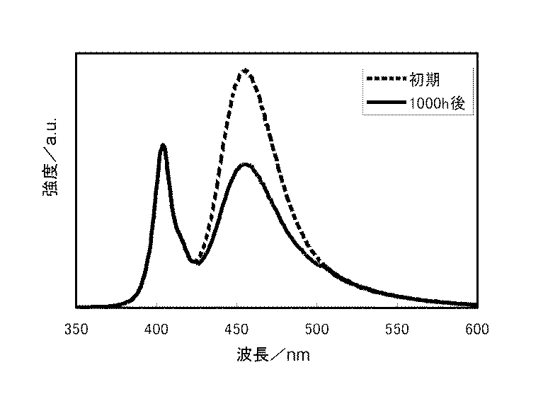
表1に示すように、実施例1に係る発光モジュールにおいて、耐光維持率(1000h点灯時)95%を達成している。また、その他の各実施例に係る発光モジュールにおいても、耐光維持率70%以上を達成している。このように、高出力の近紫外LEDを備えた発光モジュールにおいて経時での発光強度の低下が少ない青色蛍光体が実現できた。 As shown in Table 1, the light-emitting module according to Example 1 achieved a light resistance maintenance rate (during 1000 h lighting) of 95%. In addition, in the light emitting modules according to the other embodiments, the light resistance maintenance ratio of 70% or more is achieved. Thus, in the light emitting module provided with the high-power near-ultraviolet LED, a blue phosphor with little decrease in light emission intensity with time could be realized.
一方、比較例3においては、xの値が0.60とSrの含有量が多く、初期の発光強度が低い。また、比較例1、比較例4においては、いずれもxの値が0.10以下とSrの含有量が少なく、1000h後の発光強度の低下が大きく、UV耐光性が低い。そのため、一般式が(Ca1−x−y,Srx,Euy)5(PO4)3Clで表されている各実施例に係る蛍光体は、Srの含有量と相関のあるxの値が0.10<x<0.60の範囲である。 On the other hand, in Comparative Example 3, the value of x is 0.60, the Sr content is large, and the initial emission intensity is low. In Comparative Examples 1 and 4, the value of x is 0.10 or less and the Sr content is small, the emission intensity after 1000 hours is greatly reduced, and the UV light resistance is low. For this reason, the phosphors according to the examples whose general formulas are represented by (Ca 1-xy , Sr x , Eu y ) 5 (PO 4 ) 3 Cl have a correlation with the content of Sr. The value is in the range of 0.10 <x <0.60.
また、比較例2においては、yの値が0.002とEuの含有量が少なく、初期の発光強度が低い。また、参考例においては、yの値が0.060とEuの含有量が多く、初期の発光強度は高いものの、耐光維持率が70%未満である。そのため、一般式が(Ca1−x−y,Srx,Euy)5(PO4)3Clで表されている各実施例に係る蛍光体は、Euの含有量と相関のあるyの値が0.002<y<0.060の範囲である。 In Comparative Example 2, the value of y is 0.002 and the content of Eu is small, and the initial emission intensity is low. In the reference example , the value of y is 0.060 and the content of Eu is large and the initial light emission intensity is high, but the light resistance maintenance ratio is less than 70%. For this reason, the phosphors according to the examples whose general formula is represented by (Ca 1-xy , Sr x , Eu y ) 5 (PO 4 ) 3 Cl have a y value that correlates with the Eu content. The value is in the range of 0.002 <y <0.060.
また、各実施例に係る発光モジュールは、初期発光強度も高く、耐光維持率を70%以上である。各実施例の蛍光体において、SrとEuの合計含有量に対するEuの含有量の割合と相関のあるy/(x+y)の値は、0.020<y/(x+y)<0.17の範囲であり、より好ましくは、0.029≦y/(x+y)≦0.167の範囲である。 Moreover, the light emitting module according to each example has a high initial light emission intensity and a light resistance maintenance rate of 70% or more. In the phosphor of each example, the value of y / (x + y) correlated with the ratio of the Eu content to the total content of Sr and Eu is in the range of 0.020 <y / (x + y) <0.17. More preferably, the range is 0.029 ≦ y / (x + y) ≦ 0.167.
このように、一般式が(Ca1−x−y,Srx,Euy)5(PO4)3Cl(ここで、x、yは、0.10<x<0.60、0.002<y<0.060、0.02<y/(x+y)<0.17を満たす範囲である)で表されている青色蛍光体は、耐光性が向上している。また、このような青色蛍光体を含む、実施例に係る発光モジュールは、紫外線又は短波長可視光に対する青色蛍光体の耐光性が向上しているため、長期使用における発光強度の低下が抑制される。 Thus, the general formula is (Ca 1-xy , Sr x , Eu y ) 5 (PO 4 ) 3 Cl (where x and y are 0.10 <x <0.60, 0.002 The blue phosphor represented by <y <0.060 and 0.02 <y / (x + y) <0.17) has improved light resistance. Moreover, since the light resistance of the blue fluorescent substance with respect to an ultraviolet-ray or short wavelength visible light is improving the light emitting module which concerns on an Example containing such a blue fluorescent substance, the fall of the emitted light intensity in a long-term use is suppressed. .
特に、400mW以上の光出力が可能な発光素子を備える発光モジュールの蛍光体として好適である。より好ましくは、600mW以上の光出力が可能な発光素子、更により好ましくは、800mW以上の光出力が可能な発光素子と組み合わせることで、耐光性のより顕著な効果が現れる。このように、光出力の高い発光素子を用いた発光モジュールであっても長寿命を実現できる。 In particular, it is suitable as a phosphor of a light emitting module including a light emitting element capable of outputting light of 400 mW or more. More preferably, by combining with a light emitting element capable of light output of 600 mW or more, and even more preferably, a light emitting element capable of light output of 800 mW or more, a more remarkable effect of light resistance appears. Thus, even a light emitting module using a light emitting element with high light output can achieve a long life.
発光素子は、350〜420nmの波長域にピーク波長を有する紫外線又は短波長可視光を発しているものが好ましい。これにより、発光スペクトルの異なる複数種の蛍光体、例えば、各実施例に係る青色蛍光体と前述の黄色蛍光体を用いて白色光を実現できる。また、発光素子の光を直接用いずに青色光と黄色光との混色で白色光を実現できる。また、長期にわたる使用における青色光の出力の低下が抑制されるため、黄色光と混色して実現される白色光の経年による色ズレが小さくなる。 The light emitting element preferably emits ultraviolet light or short wavelength visible light having a peak wavelength in a wavelength range of 350 to 420 nm. Thereby, white light is realizable using several types of fluorescent substance from which an emission spectrum differs, for example, the blue fluorescent substance which concerns on each Example, and the above-mentioned yellow fluorescent substance. Also, white light can be realized by mixing blue light and yellow light without directly using light from the light emitting element. In addition, since a decrease in the output of blue light over a long period of use is suppressed, color misregistration due to aging of white light realized by mixing with yellow light is reduced.
以上、本発明を実施の形態や実施例をもとに説明した。この実施の形態は例示であり、それらの各構成要素や各処理プロセスの組合せにいろいろな変形例が可能なこと、またそうした変形例も本発明の範囲にあることは当業者に理解されるところである。 The present invention has been described based on the embodiments and examples. This embodiment is an exemplification, and it will be understood by those skilled in the art that various modifications can be made to combinations of the respective constituent elements and processing processes, and such modifications are also within the scope of the present invention. is there.
本発明の発光モジュールは種々の灯具、例えば照明用灯具、ディスプレイ用バックライト、車両用灯具等に利用することができる。 The light emitting module of the present invention can be used for various lamps, for example, lighting lamps, display backlights, vehicle lamps and the like.
10 発光モジュール、 12 マウント部材、 14 半導体発光素子、 16 枠部材、 18 蛍光部材。
DESCRIPTION OF
Claims (5)
前記紫外線又は短波長可視光により励起され、可視光を発光する青色蛍光体と、を備え、
前記青色蛍光体は、一般式が(Ca1−x−y,Srx,Euy)5(PO4)3Cl(ここで、x、yは、0.10<x<0.60、0.002<y<0.060、0.038≦y/(x+y)<0.17を満たす範囲である)で表されていることを特徴とする発光モジュール。 A light emitting element emitting ultraviolet light or short wavelength visible light;
A blue phosphor that is excited by the ultraviolet light or short-wavelength visible light and emits visible light,
The blue phosphor has a general formula of (Ca 1-xy , Sr x , Eu y ) 5 (PO 4 ) 3 Cl (where x and y are 0.10 <x <0.60, 0 .002 <y <0.060 and 0.038 ≦ y / (x + y) <0.17).
Priority Applications (4)
| Application Number | Priority Date | Filing Date | Title |
|---|---|---|---|
| JP2011213411A JP5872828B2 (en) | 2011-09-28 | 2011-09-28 | Light emitting module and phosphor |
| US13/611,922 US8497625B2 (en) | 2011-09-28 | 2012-09-12 | Light emitting module and phosphor |
| CN201210370133.9A CN103035822B (en) | 2011-09-28 | 2012-09-27 | Luminescence component and fluorophor |
| EP12186305.4A EP2574653B1 (en) | 2011-09-28 | 2012-09-27 | Light emitting module and phosphor |
Applications Claiming Priority (1)
| Application Number | Priority Date | Filing Date | Title |
|---|---|---|---|
| JP2011213411A JP5872828B2 (en) | 2011-09-28 | 2011-09-28 | Light emitting module and phosphor |
Publications (2)
| Publication Number | Publication Date |
|---|---|
| JP2013072041A JP2013072041A (en) | 2013-04-22 |
| JP5872828B2 true JP5872828B2 (en) | 2016-03-01 |
Family
ID=47325795
Family Applications (1)
| Application Number | Title | Priority Date | Filing Date |
|---|---|---|---|
| JP2011213411A Expired - Fee Related JP5872828B2 (en) | 2011-09-28 | 2011-09-28 | Light emitting module and phosphor |
Country Status (4)
| Country | Link |
|---|---|
| US (1) | US8497625B2 (en) |
| EP (1) | EP2574653B1 (en) |
| JP (1) | JP5872828B2 (en) |
| CN (1) | CN103035822B (en) |
Families Citing this family (8)
| Publication number | Priority date | Publication date | Assignee | Title |
|---|---|---|---|---|
| JP2013162020A (en) | 2012-02-07 | 2013-08-19 | Seiko Epson Corp | Wavelength conversion element, light source device, and projector |
| JP2013162021A (en) * | 2012-02-07 | 2013-08-19 | Seiko Epson Corp | Wavelength conversion element, light source device, and projector |
| JP6195117B2 (en) * | 2013-12-03 | 2017-09-13 | パナソニックIpマネジメント株式会社 | Acid chloride phosphor, light emitting device, lighting device, and vehicle |
| JP2019016632A (en) * | 2017-07-04 | 2019-01-31 | 日亜化学工業株式会社 | Light-emitting device |
| WO2019106864A1 (en) * | 2017-11-28 | 2019-06-06 | 京セラ株式会社 | Light-emitting device and illumination device |
| EP3758077A4 (en) * | 2018-02-23 | 2021-11-24 | Kyocera Corporation | LIGHT EMITTING DEVICE AND LIGHTING DEVICE |
| CN110630976A (en) * | 2018-06-22 | 2019-12-31 | 株式会社小糸制作所 | Lighting module |
| JP7174238B2 (en) * | 2018-11-29 | 2022-11-17 | 日亜化学工業株式会社 | Halophosphate phosphor and light-emitting device |
Family Cites Families (12)
| Publication number | Priority date | Publication date | Assignee | Title |
|---|---|---|---|---|
| US4038204A (en) * | 1968-05-03 | 1977-07-26 | Westinghouse Electric Corporation | Alkaline-earth metal halophosphate luminescent composition activated by divalent europium and method of preparing same |
| JP2001172623A (en) * | 1999-12-20 | 2001-06-26 | Toshiba Corp | Phosphor and fluorescent lamp using the same |
| DE10009916A1 (en) * | 2000-03-01 | 2001-09-13 | Philips Corp Intellectual Pty | Plasma screen comprises a phosphor layer containing an europium-activated phosphor and a UV-C light-emitting phosphor |
| CN1253526C (en) * | 2003-08-05 | 2006-04-26 | 北京大学 | Three components of white luminescent powder exeitated by visual purple and its preparing method |
| JP4389513B2 (en) * | 2003-08-08 | 2009-12-24 | 三菱化学株式会社 | Light emitting device, lighting device, and image display device |
| US7573072B2 (en) * | 2004-03-10 | 2009-08-11 | Lumination Llc | Phosphor and blends thereof for use in LEDs |
| US7391060B2 (en) * | 2004-04-27 | 2008-06-24 | Matsushita Electric Industrial Co., Ltd. | Phosphor composition and method for producing the same, and light-emitting device using the same |
| JP4890017B2 (en) * | 2005-01-26 | 2012-03-07 | 株式会社小糸製作所 | Blue light emitting phosphor and light emitting module using the same |
| US7857992B2 (en) * | 2005-03-14 | 2010-12-28 | Kabushiki Kaisha Toshiba | White light-emitting lamp, backlight using same, display and illuminating device |
| JP4965840B2 (en) * | 2005-09-29 | 2012-07-04 | 株式会社東芝 | Manufacturing method of white light emitting LED lamp, manufacturing method of backlight using the same, and manufacturing method of liquid crystal display device |
| WO2009005035A1 (en) * | 2007-06-29 | 2009-01-08 | Mitsubishi Chemical Corporation | Phosphor, method for producing phosphor, phosphor-containing composition, and light-emitting device |
| JP2009057455A (en) * | 2007-08-31 | 2009-03-19 | Tottori Univ | Phosphor |
-
2011
- 2011-09-28 JP JP2011213411A patent/JP5872828B2/en not_active Expired - Fee Related
-
2012
- 2012-09-12 US US13/611,922 patent/US8497625B2/en not_active Expired - Fee Related
- 2012-09-27 EP EP12186305.4A patent/EP2574653B1/en not_active Not-in-force
- 2012-09-27 CN CN201210370133.9A patent/CN103035822B/en not_active Expired - Fee Related
Also Published As
| Publication number | Publication date |
|---|---|
| EP2574653A2 (en) | 2013-04-03 |
| US8497625B2 (en) | 2013-07-30 |
| US20130076234A1 (en) | 2013-03-28 |
| CN103035822A (en) | 2013-04-10 |
| EP2574653A3 (en) | 2014-08-06 |
| CN103035822B (en) | 2015-08-26 |
| JP2013072041A (en) | 2013-04-22 |
| EP2574653B1 (en) | 2018-09-19 |
Similar Documents
| Publication | Publication Date | Title |
|---|---|---|
| JP5872828B2 (en) | Light emitting module and phosphor | |
| TWI415923B (en) | Lighting system containing radiation source and fluorescent material | |
| US8979318B2 (en) | Light source with a low color temperature | |
| CN1898357A (en) | Phosphor and light emitting device using the same | |
| JP6223988B2 (en) | Phosphor, light emitting device and lighting device | |
| US10340426B2 (en) | Phosphor and illumination device utilizing the same | |
| WO2012165032A1 (en) | Light-emitting device | |
| JP2008195779A (en) | Light emitting device | |
| AU2015284080B2 (en) | Oxyfluoride phosphor compositions and lighting apparatus thereof | |
| CN1233046C (en) | A method for producing a white light emitting diode light source | |
| JP2013144794A (en) | Oxynitride-based phosphor and light-emitting device using the same | |
| JP5527445B2 (en) | LIGHT EMITTING ELEMENT, LIGHTING DEVICE USING SAME, AND IMAGE DISPLAY DEVICE | |
| JP6640753B2 (en) | Phosphor composition and lighting fixture comprising the same | |
| JP2013089769A (en) | Light emitting module | |
| JP4890017B2 (en) | Blue light emitting phosphor and light emitting module using the same | |
| JP5273108B2 (en) | LIGHT EMITTING ELEMENT, LIGHTING DEVICE USING SAME, AND IMAGE DISPLAY DEVICE | |
| JP4732888B2 (en) | Red light emitting phosphor and light emitting module using the same | |
| TWI609945B (en) | Phosphor, illuminating device and illuminating device | |
| KR102092676B1 (en) | Light emitting device | |
| TWI572694B (en) | Yellow-emitting phosphor and light-emitting device package using the same | |
| JP2015154048A (en) | Light-emitting device, and lighting apparatus and image display apparatus using the same |
Legal Events
| Date | Code | Title | Description |
|---|---|---|---|
| A621 | Written request for application examination |
Free format text: JAPANESE INTERMEDIATE CODE: A621 Effective date: 20140806 |
|
| A977 | Report on retrieval |
Free format text: JAPANESE INTERMEDIATE CODE: A971007 Effective date: 20150519 |
|
| A131 | Notification of reasons for refusal |
Free format text: JAPANESE INTERMEDIATE CODE: A131 Effective date: 20150609 |
|
| A521 | Request for written amendment filed |
Free format text: JAPANESE INTERMEDIATE CODE: A523 Effective date: 20150804 |
|
| A02 | Decision of refusal |
Free format text: JAPANESE INTERMEDIATE CODE: A02 Effective date: 20150908 |
|
| A521 | Request for written amendment filed |
Free format text: JAPANESE INTERMEDIATE CODE: A523 Effective date: 20151203 |
|
| A911 | Transfer to examiner for re-examination before appeal (zenchi) |
Free format text: JAPANESE INTERMEDIATE CODE: A911 Effective date: 20151211 |
|
| TRDD | Decision of grant or rejection written | ||
| A01 | Written decision to grant a patent or to grant a registration (utility model) |
Free format text: JAPANESE INTERMEDIATE CODE: A01 Effective date: 20160112 |
|
| A61 | First payment of annual fees (during grant procedure) |
Free format text: JAPANESE INTERMEDIATE CODE: A61 Effective date: 20160114 |
|
| R150 | Certificate of patent or registration of utility model |
Ref document number: 5872828 Country of ref document: JP Free format text: JAPANESE INTERMEDIATE CODE: R150 |
|
| LAPS | Cancellation because of no payment of annual fees |