JP5832737B2 - Ultrasonic diagnostic apparatus and ultrasonic image processing apparatus - Google Patents
Ultrasonic diagnostic apparatus and ultrasonic image processing apparatus Download PDFInfo
- Publication number
- JP5832737B2 JP5832737B2 JP2010245266A JP2010245266A JP5832737B2 JP 5832737 B2 JP5832737 B2 JP 5832737B2 JP 2010245266 A JP2010245266 A JP 2010245266A JP 2010245266 A JP2010245266 A JP 2010245266A JP 5832737 B2 JP5832737 B2 JP 5832737B2
- Authority
- JP
- Japan
- Prior art keywords
- image
- ultrasonic
- unit
- luminance
- luminance value
- Prior art date
- Legal status (The legal status is an assumption and is not a legal conclusion. Google has not performed a legal analysis and makes no representation as to the accuracy of the status listed.)
- Active
Links
- 238000000354 decomposition reaction Methods 0.000 claims description 29
- 230000015572 biosynthetic process Effects 0.000 claims description 26
- 238000003786 synthesis reaction Methods 0.000 claims description 26
- 238000004364 calculation method Methods 0.000 claims description 18
- 210000004204 blood vessel Anatomy 0.000 claims description 14
- 239000000523 sample Substances 0.000 claims description 14
- 238000002604 ultrasonography Methods 0.000 claims description 13
- 239000002131 composite material Substances 0.000 claims description 7
- 230000004069 differentiation Effects 0.000 claims description 6
- 230000002194 synthesizing effect Effects 0.000 claims description 6
- 230000002792 vascular Effects 0.000 description 31
- 239000000203 mixture Substances 0.000 description 25
- 230000001629 suppression Effects 0.000 description 24
- 230000004048 modification Effects 0.000 description 22
- 238000012986 modification Methods 0.000 description 22
- 210000001519 tissue Anatomy 0.000 description 18
- 238000000034 method Methods 0.000 description 17
- 238000010586 diagram Methods 0.000 description 10
- 230000005540 biological transmission Effects 0.000 description 8
- 238000001514 detection method Methods 0.000 description 8
- 230000008569 process Effects 0.000 description 6
- 230000001965 increasing effect Effects 0.000 description 5
- 230000007423 decrease Effects 0.000 description 3
- 238000003672 processing method Methods 0.000 description 3
- 230000017531 blood circulation Effects 0.000 description 2
- 230000008859 change Effects 0.000 description 2
- 238000009792 diffusion process Methods 0.000 description 2
- 230000000694 effects Effects 0.000 description 2
- 230000006872 improvement Effects 0.000 description 2
- 230000009466 transformation Effects 0.000 description 2
- 210000000988 bone and bone Anatomy 0.000 description 1
- 239000002872 contrast media Substances 0.000 description 1
- 230000003111 delayed effect Effects 0.000 description 1
- 239000006185 dispersion Substances 0.000 description 1
- 230000002708 enhancing effect Effects 0.000 description 1
- 239000000284 extract Substances 0.000 description 1
- 238000009499 grossing Methods 0.000 description 1
- 239000004973 liquid crystal related substance Substances 0.000 description 1
- 239000011159 matrix material Substances 0.000 description 1
- 210000003205 muscle Anatomy 0.000 description 1
- 238000001308 synthesis method Methods 0.000 description 1
Images


Classifications
-
- A—HUMAN NECESSITIES
- A61—MEDICAL OR VETERINARY SCIENCE; HYGIENE
- A61B—DIAGNOSIS; SURGERY; IDENTIFICATION
- A61B8/00—Diagnosis using ultrasonic, sonic or infrasonic waves
- A61B8/08—Clinical applications
- A61B8/0891—Clinical applications for diagnosis of blood vessels
-
- A—HUMAN NECESSITIES
- A61—MEDICAL OR VETERINARY SCIENCE; HYGIENE
- A61B—DIAGNOSIS; SURGERY; IDENTIFICATION
- A61B8/00—Diagnosis using ultrasonic, sonic or infrasonic waves
- A61B8/48—Diagnostic techniques
- A61B8/488—Diagnostic techniques involving Doppler signals
-
- G—PHYSICS
- G06—COMPUTING; CALCULATING OR COUNTING
- G06T—IMAGE DATA PROCESSING OR GENERATION, IN GENERAL
- G06T5/00—Image enhancement or restoration
- G06T5/20—Image enhancement or restoration using local operators
-
- G—PHYSICS
- G06—COMPUTING; CALCULATING OR COUNTING
- G06T—IMAGE DATA PROCESSING OR GENERATION, IN GENERAL
- G06T5/00—Image enhancement or restoration
- G06T5/70—Denoising; Smoothing
-
- G—PHYSICS
- G06—COMPUTING; CALCULATING OR COUNTING
- G06T—IMAGE DATA PROCESSING OR GENERATION, IN GENERAL
- G06T2207/00—Indexing scheme for image analysis or image enhancement
- G06T2207/10—Image acquisition modality
- G06T2207/10132—Ultrasound image
-
- G—PHYSICS
- G06—COMPUTING; CALCULATING OR COUNTING
- G06T—IMAGE DATA PROCESSING OR GENERATION, IN GENERAL
- G06T2207/00—Indexing scheme for image analysis or image enhancement
- G06T2207/20—Special algorithmic details
- G06T2207/20172—Image enhancement details
- G06T2207/20192—Edge enhancement; Edge preservation
-
- G—PHYSICS
- G06—COMPUTING; CALCULATING OR COUNTING
- G06T—IMAGE DATA PROCESSING OR GENERATION, IN GENERAL
- G06T2207/00—Indexing scheme for image analysis or image enhancement
- G06T2207/30—Subject of image; Context of image processing
- G06T2207/30004—Biomedical image processing
- G06T2207/30101—Blood vessel; Artery; Vein; Vascular
Landscapes
- Health & Medical Sciences (AREA)
- Life Sciences & Earth Sciences (AREA)
- Engineering & Computer Science (AREA)
- Physics & Mathematics (AREA)
- Heart & Thoracic Surgery (AREA)
- Surgery (AREA)
- Pathology (AREA)
- Radiology & Medical Imaging (AREA)
- Biophysics (AREA)
- Biomedical Technology (AREA)
- Theoretical Computer Science (AREA)
- Medical Informatics (AREA)
- Molecular Biology (AREA)
- Nuclear Medicine, Radiotherapy & Molecular Imaging (AREA)
- Animal Behavior & Ethology (AREA)
- General Health & Medical Sciences (AREA)
- Public Health (AREA)
- Veterinary Medicine (AREA)
- General Physics & Mathematics (AREA)
- Vascular Medicine (AREA)
- Ultra Sonic Daignosis Equipment (AREA)
- Image Processing (AREA)
Description
本発明の実施形態は、超音波診断装置及び超音波画像処理装置に関する。 Embodiments described herein relate generally to an ultrasonic diagnostic apparatus and an ultrasonic image processing apparatus.
超音波診断装置は、超音波プローブに内蔵された振動子から被検体に超音波を送波し、被検体により反射された超音波を振動子を介して受波し、受波された超音波に応じたエコー信号に基づいて超音波画像を発生している。超音波画像は、被検体組織に関する情報以外に、各種のノイズや超音波の干渉によるスペックルを含んでいる。ノイズやスペックルは、超音波画像の画質を劣化させている。 The ultrasonic diagnostic apparatus transmits an ultrasonic wave from a transducer built in an ultrasonic probe to a subject, receives an ultrasonic wave reflected by the subject through the transducer, and receives the received ultrasonic wave. An ultrasonic image is generated based on an echo signal corresponding to the signal. The ultrasonic image includes speckles due to interference of various noises and ultrasonic waves in addition to information on the subject tissue. Noise and speckle deteriorate the image quality of the ultrasonic image.
ノイズやスペックルを低減し被検体組織に関する情報を強調するために、超音波画像の各画素のエッジ情報を算出し、算出されたエッジ情報に応じたフィルタを画素に適用する方法がある。このフィルタは、具体的には、エッジ方向に平滑化し、エッジ方向の垂直方向に鮮鋭化している。このフィルタを利用した画像処理方法は、例えば、血管画像の画質向上に利用されている。 In order to reduce noise and speckles and emphasize information related to a subject tissue, there is a method of calculating edge information of each pixel of an ultrasonic image and applying a filter corresponding to the calculated edge information to the pixel. Specifically, this filter is smoothed in the edge direction and sharpened in the vertical direction of the edge direction. An image processing method using this filter is used to improve the image quality of blood vessel images, for example.
血管に関する超音波画像の観察のためには、血管壁内膜領域は全体的に強調され、内膜方向に平滑化され、血管壁内膜領域の近傍に位置する実質領域は強調されないことが望ましい。上記の画像処理方法により、血管壁内膜領域がエッジとして検出されるが、輝度変化の大きい実質領域もエッジとして検出されてしまう。そのため、血管壁内膜領域が強調されると、実質領域も強調されてしまう。このように上記の画像処理方法を適用することにより、血管壁内膜領域の表示を最適化しようとすると、血管壁内膜領域近傍の実質領域が明るくなり過ぎてしまう場合がある。 For observation of ultrasound images related to blood vessels, it is desirable that the vascular wall intima region is entirely emphasized, smoothed in the intima direction, and the substantial region located in the vicinity of the vascular wall intima region is not emphasized . By the above image processing method, the vascular wall intima region is detected as an edge, but a substantial region having a large luminance change is also detected as an edge. Therefore, when the vascular wall intima region is emphasized, the substantial region is also emphasized. By applying the above-described image processing method as described above, when trying to optimize the display of the vascular wall intimal region, the substantial region near the vascular wall intimal region may become too bright.
目的は、超音波画像の画質の向上を可能とする超音波診断装置及び超音波画像処理装置を提供することにある。 An object is to provide an ultrasonic diagnostic apparatus and an ultrasonic image processing apparatus capable of improving the image quality of an ultrasonic image.
本実施形態に係る超音波診断装置は、超音波を被検体に向けて送波し、前記被検体により反射された超音波を受波し、前記受波された超音波に応じたエコー信号を発生する超音波プローブと、前記発生されたエコー信号に基づいて前記被検体に関する超音波画像を発生する発生部と、前記発生された超音波画像に含まれる複数の画素の各々について輝度値の空間微分に基づいて前記画素のエッジ情報を算出する算出部と、前記算出されたエッジ情報に応じたフィルタ特性を有するフィルタを前記超音波画像に施し、前記超音波画像からフィルタ画像を発生するフィルタ処理部と、前記発生されたフィルタ画像に含まれる複数の画素の各々について輝度値を前記エッジ情報に応じて上昇し、前記フィルタ画像から強調画像を発生する強調部と、前記発生された強調画像の輝度値に応じた合成比率に従って前記強調画像と前記超音波画像との合成画像を発生する合成部と、を具備する。 The ultrasonic diagnostic apparatus according to the present embodiment transmits an ultrasonic wave toward a subject, receives an ultrasonic wave reflected by the subject, and receives an echo signal corresponding to the received ultrasonic wave. A brightness value space for each of a plurality of pixels included in the generated ultrasound image, an ultrasound probe that is generated, a generation unit that generates an ultrasound image related to the subject based on the generated echo signal, and A filter unit that calculates edge information of the pixel based on the differentiation, and a filter process that generates a filter image from the ultrasonic image by applying a filter having a filter characteristic corresponding to the calculated edge information to the ultrasonic image And an emphasis unit that raises a luminance value for each of a plurality of pixels included in the generated filter image according to the edge information, and generates an emphasized image from the filter image; Comprising a combining unit for generating a composite image of the said enhanced image according to the synthesis ratio corresponding to the luminance value of the serial generation has been enhanced image wherein the ultrasound image.
以下、図面を参照しながら本実施形態に係わる超音波診断装置及び超音波画像処理装置を説明する。 Hereinafter, an ultrasonic diagnostic apparatus and an ultrasonic image processing apparatus according to the present embodiment will be described with reference to the drawings.
図1は、本実施形態に係る超音波診断装置1の構成を示す図を示している。図1に示すように超音波診断装置1は、超音波プローブ10、送信部20、受信部30、Bモード処理部40、カラードプラ処理部50、画像発生部60、画像処理部70、記憶部80、及び表示部90を備えている。
FIG. 1 shows a diagram illustrating a configuration of an ultrasonic
超音波プローブ10は、複数の振動子を有している。超音波プローブ10は、送信部20からの駆動信号を受けて被検体に向けて超音波を送波する。被検体に送波された超音波は、体内組織の音響インピーダンスの不連続面で次々と反射される。反射された超音波は、超音波プローブ10に受波される。超音波プローブ10は、受波された超音波の強度に応じた電気信号(エコー信号)を発生する。エコー信号の振幅は、反射された不連続面における音響インピーダンスの差に依存する。また、移動している血流や心臓壁等の移動体の表面で超音波が反射された場合、エコー信号は、ドプラ効果により移動体の超音波送信方向の速度成分に依存した周波数偏移を受ける。
The
送信部20は、超音波プローブ10を介して被検体に超音波を繰り返し送信する。より詳細には、送信部20は、超音波の送信用に図示しないレートパルス発生回路、送信遅延回路、及び駆動パルス発生回路等を有している。レートパルス発生回路は、所定のレート周波数frHz(周期;1/fr秒)で、レートパルスをチャンネル毎に繰り返し発生する。遅延回路は、チャンネル毎に超音波をビーム状に集束させ且つ送信指向性を決定するのに必要な遅延時間を各レートパルスに与える。駆動パルス発生回路は、各遅延されたレートパルスに基づくタイミングで、超音波プローブ10に駆動パルスを印加する。
The
受信部30は、超音波プローブ10を介して被検体からの超音波を繰り返し受信する。より詳細には、受信部30は、超音波の受信用に図示しないアンプ回路、A/D変換器、受信遅延回路、及び加算器等を有している。アンプ回路は、超音波プローブ10からのエコー信号をチャンネル毎に増幅する。A/D変換器は、増幅されたエコー信号をチャンネル毎にアナログ信号からデジタル信号に変換する。受信遅延回路は、デジタル信号に変換されたエコー信号に対し、チャンネル毎にビーム状に集束させ且つ受信指向性を決定するのに必要な遅延時間を与える。加算器は、遅延時間が与えられた各エコー信号を加算する。加算処理により、受信ビームに対応する受信信号が発生される。このようにして受信部30は、複数の受信ビームにそれぞれ対応する複数の受信信号を発生する。受信信号は、Bモード処理部40とカラードプラ処理部50とに供給される。
The
Bモード処理部40は、受信部30からの受信信号を対数増幅し、対数増幅された受信信号を包絡線検波することで、エコー信号の強度を輝度で表現するBモード信号のデータを発生する。発生されたBモード信号のデータは、画像発生部60に供給される。
The B-
カラードプラ処理部50は、受信部30からの受信信号に自己相関演算を施し、ドプラ効果による血流や組織、造影剤エコー成分を抽出し、平均速度や分散、パワー等の血流情報の強度をカラーで表現するドプラ信号のデータを発生する。発生されたドプラ信号のデータは、画像発生部60に供給される。
The color
画像発生部60は、Bモード処理部40からのBモード信号に基づいて、被検体に関するBモード画像を発生する。具体的には、画像発生部60は、スキャンコンバータにより構成される。画像発生部60は、Bモード信号のスキャン方式を超音波スキャン方式から表示デバイス方式に変換することにより、Bモード画像を発生する。Bモード画像の画素は、由来するBモード信号の強度に応じた輝度値を有している。同様にして画像発生部60は、カラードプラ処理部50からのドプラ信号に基づいて、被検体に関するドプラ画像を発生する。ドプラ画像の画素は、由来するドプラ信号の強度に応じたカラー値を有している。以下、Bモード画像とドプラ画像とは、記憶部80と画像処理部70とに供給される。
The
画像処理部70は、画像発生部60又は記憶部70からのBモード画像に対して画像処理を実行する。画像処理により、スペックルやノイズが低減され、且つ非注目領域が強調され過ぎずに注目領域が適切に強調されたBモード画像を発生する。画像処理の詳細については後述する。画像処理が施されたBモード画像は、記憶部80と表示部90とに供給される。
The
表示部90は、画像処理部70により画像処理が施されたBモード画像を表示デバイスに表示する。この際、Bモード画像には、ドプラ画像が重ねられても良い。表示デバイスとしては、例えばCRTディスプレイや、液晶ディスプレイ、有機ELディスプレイ、プラズマディスプレイ等の表示デバイスが適宜利用可能である。
The
なお画像処理部70、記憶部80、及び表示部90は、超音波画像処理装置100を構成する。この超音波画像処理装置100は、図1に示すように、超音波診断装置1に組み込まれていてもよいし、超音波診断装置1とは別体のコンピュータに組み込まれていても良い。
The
以下、本実施形態に係る画像処理部70の詳細について説明する。なお、画像処理部70の処理対象のBモード画像は、被検体の血管に関するBモード画像であるとする。しかしながら、本実施形態はこれに限定されず、画像処理部70の処理対象のBモード画像は、血管以外の骨や筋肉等の成形組織に関するBモード画像にも適用可能である。
Details of the
図2は、画像処理部70の構成を示す図である。図2に示すように、画像処理部70は、多重解像度分解/合成を行なうために、複数階層(レベル)からなる多重構造を有している。本実施形態においては、説明を具体的に行うため、多重解像度分解/合成の最高レベルは、3としている。しかしながら本実施形態は、これに限定する必要はない。多重解像度分解/合成は、レベル1からレベルn(ただし、nは2以上の自然数)の範囲で行なわれればよい。また本実施形態では、多重解像度分解/合成の一例として離散ウェーブレット変換/逆変換を採用する。しかしながら本実施形態は、これに限定する必要はない。例えば、多重解像度分解/合成として、ラプラシアン・ピラミッド(Laplacian pyramid)法やガボール(Gabor)変換/逆変換等の既存の多重解像度分解/合成法を採用してもよい。
FIG. 2 is a diagram illustrating a configuration of the
図2に示すように、本実施形態に係る画像処理部70は、レベル毎に多重解像度分解部71(71―1、71―2、71―3)、最適輝度画像発生部73(73―1、73―2、73―3)、高域画像制御部75(75―1、75―2、75―3)、及び多重解像度合成部77(77―1、77―2、77―3)を備えている。
As shown in FIG. 2, the
多重解像度分解部71は、処理対象画像に基づいて、処理対象画像の解像度よりも低い解像度を有する低域画像と高域画像とを発生する。例えば、多重解像度分解部71は、処理対象画像に離散ウェーブレット変換を施す。離散ウェーブレット変換において多重解像度分解部71は、xy直交座標の各軸方向(各次元)に1次元の低域フィルタと高域フィルタとをそれぞれ適用する。これらフィルタの適用により、処理対象画像が1枚の低域画像と3枚の高域画像とに分解される。低域画像は、処理対象画像が有する空間周波数成分のうちの低周波成分を含む。各高域画像は、処理対象画像が有する空間周波数成分のうちの少なくとも1方向に関する高周波成分を含む。分解後の各画像の各座標軸あたりの標本数は、分解前の各座標軸あたりの標本数の半分に縮小される。 The multi-resolution decomposition unit 71 generates a low-frequency image and a high-frequency image having a resolution lower than the resolution of the processing target image based on the processing target image. For example, the multi-resolution decomposition unit 71 performs discrete wavelet transform on the processing target image. In the discrete wavelet transform, the multiresolution decomposition unit 71 applies a one-dimensional low-pass filter and a high-pass filter in each axial direction (each dimension) of the xy orthogonal coordinates. By applying these filters, the processing target image is decomposed into one low-frequency image and three high-frequency images. The low frequency image includes a low frequency component among the spatial frequency components of the processing target image. Each high-frequency image includes a high-frequency component related to at least one direction among the spatial frequency components of the processing target image. The number of samples per coordinate axis of each image after decomposition is reduced to half of the number of samples per coordinate axis before decomposition.
多重解像度分解部71が最低レベル(図2の場合レベル1)に属する場合、処理対象画像は、画像発生部60又は記憶部70からのBモード画像である。多重解像度分解部71が最低レベル(図2の場合レベル1)に属さない場合、処理対象画像は、1レベル下の多重解像度分解部71からの低域画像である。
When the multi-resolution decomposition unit 71 belongs to the lowest level (
多重解像度分解部71が最高レベル(図2の場合レベル3)に属する場合、発生された低域画像は、同最高レベルの最適輝度画像発生部73―3に供給される。多重解像度分解部71が最高レベルに属さない場合、発生された低域画像は、1レベル上のレベルに属する多重解像度分解部71に供給される。発生された3枚の高域画像は、同レベルに属する高域画像制御部75に供給される。 When the multi-resolution decomposition unit 71 belongs to the highest level (level 3 in the case of FIG. 2), the generated low-frequency image is supplied to the optimum luminance image generation unit 73-3 having the highest level. When the multi-resolution decomposition unit 71 does not belong to the highest level, the generated low-frequency image is supplied to the multi-resolution decomposition unit 71 belonging to the level one level higher. The generated three high frequency images are supplied to the high frequency image control unit 75 belonging to the same level.
最適輝度画像発生部73は、処理対象画像に含まれる複数の画素の各々についてエッジ情報を算出する。エッジ情報は、同レベルの高域画像制御部75に供給される。また、最適輝度画像発生部73は、エッジ情報を利用して処理対象画像から、スペックルやノイズが低減され且つ高輝度領域が強調され過ぎずに非高輝度領域のエッジ領域が適切に強調された画像を発生する。発生された画像を最適輝度画像と呼ぶことにする。最適輝度画像は、同レベルの多重解像度合成部77に供給される。
The optimum luminance
最適輝度画像発生部73が最高レベル(図2の場合レベル3)に属する場合、処理対象画像は、同最高レベルに属する多重解像度分解部71からの低域画像である。最適輝度画像発生部73が最高レベルに属さない場合、処理対象画像は、1レベル上のレベルに属する多重解像度合成部77からの画像である。
When the optimum luminance
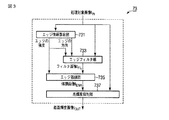
図3は、最適輝度画像発生部73の構成を示す図である。図3に示すように、最適輝度画像発生部73は、エッジ情報算出部731、エッジフィルタ部733、エッジ強調部735、及び高輝度抑制部737を有する。
FIG. 3 is a diagram showing a configuration of the optimum luminance
エッジ情報算出部731は、処理対象画像IINに含まれる複数の画素の各々についてエッジ情報を算出する。具体的には、エッジ情報算出部731は、まず処理対象画素と処理対象画素の近傍画素とを利用して各座標軸に沿って空間微分し、空間微分値を算出する。そしてエッジ情報算出部731は、算出された空間微分値に基づいて処理対象画素に関するエッジの強度と方向とを算出する。このエッジの強度と方向との組合せがエッジ情報である。より詳細には、エッジ情報算出部731は、空間微分値を利用して処理対象画素の構造テンソル(structure tensor)の複数の要素を算出する。エッジ情報算出部731は、算出された複数の要素に線形代数演算に施し、構造テンソルの2つの固有値と2つの固有ベクトルとを算出する。2つの固有ベクトルのうちの一方がエッジに沿う方向を意味し、他方がエッジに垂直な方向を意味する。ここでエッジに沿う方向をエッジ方向と呼ぶことにする。固有値は、エッジの強度に依存する。 The edge information calculation unit 731 calculates edge information for each of a plurality of pixels included in the processing target image IIN . Specifically, the edge information calculation unit 731 first performs spatial differentiation along each coordinate axis using a processing target pixel and a neighboring pixel of the processing target pixel, and calculates a spatial differential value. Then, the edge information calculation unit 731 calculates the edge strength and direction related to the processing target pixel based on the calculated spatial differential value. The combination of edge strength and direction is edge information. More specifically, the edge information calculation unit 731 calculates a plurality of elements of the structure tensor of the processing target pixel using the spatial differential value. The edge information calculation unit 731 performs linear algebra calculation on the calculated plurality of elements, and calculates two eigenvalues and two eigenvectors of the structure tensor. One of the two eigenvectors means a direction along the edge, and the other means a direction perpendicular to the edge. Here, the direction along the edge is referred to as the edge direction. The eigenvalue depends on the strength of the edge.
なおエッジ情報の算出方法は、構造テンソルを利用する方法に限定されない。例えば、構造テンソルの代わりにヘッセ行列(Hessian matrix)を利用してエッジ情報を算出しても良い。 Note that the edge information calculation method is not limited to a method using a structure tensor. For example, the edge information may be calculated using a Hessian matrix instead of the structure tensor.
エッジフィルタ部733は、エッジ情報に応じたフィルタ特性を有するフィルタを入力画像に施す。ここでエッジ情報に応じたフィルタ特性を有するフィルタをエッジフィルタと呼ぶことにする。具体的には、エッジフィルタ部733は、処理対象画像IINに含まれる複数の画素の各々についてエッジフィルタを算出する。エッジフィルタは、エッジ方向に沿ってエッジ領域に鮮鋭化を施し、エッジ方向の垂直方向に沿ってエッジ領域に平滑化を施す特性を有する。エッジフィルタとしては、例えば、エッジ情報に基づいて算出される非線形異方性拡散フィルタ(Nonlinear Anisotropic Diffusion Filter)が挙げられる。エッジフィルタ部733は、各画素にエッジフィルタを施すことによって、処理対象画像IINに含まれるエッジ領域を強調し、非エッジ領域を抑制する。ここでエッジフィルタ部733の出力画像をフィルタ画像IFILと呼ぶことにする。
The
エッジ強調部735は、フィルタ画像IFILに含まれる複数の画素の各々について輝度値をエッジ情報に応じて上昇する。ここでエッジ強調部735の出力画像を強調画像IENHと呼ぶことにする。具体的には、エッジ強調部735は、各画素についてエッジの強度と閾値とを比較し、閾値よりも大きいエッジの強度を有する画素をエッジ領域に設定し、閾値よりも小さいエッジの強度を有する画素を非エッジ領域に設定する。そしてエッジ強調部735は、エッジ領域に含まれる画素の輝度値を、エッジの強度に応じた増加量だけ増加させる。増加量は、例えば、パラメータaENHとエッジの強度EEDGEとの積により規定される。エッジ領域の強調は、例えば、以下の(1)式により表現される。なおIENHは、強調画像の画素の輝度値を表し、IFILは、フィルタ画像の画素の輝度値を意味する。
The
IENH=IFIL+(1+aENH・EEDGE) ・・・(1)
パラメータaENHは、輝度値の上昇度合いを調節するためのパラメータである。パラメータaENHは、操作者により任意の値に設定される。なお、エッジ領域が強調され過ぎてはならないので、パラメータaENHは、例えば、0.02程度の微小量に設定される。このようにしてエッジ強調部735は、エッジの強度が比較的大きい画素の輝度値を若干上昇させることにより、フィルタ画像IFIL上のエッジ領域をさらに強調させる。
I ENH = I FIL + (1 + a ENH · E EDGE ) (1)
The parameter a ENH is a parameter for adjusting the increase degree of the luminance value. The parameter a ENH is set to an arbitrary value by the operator. Since the edge region must not be emphasized too much, the parameter a ENH is set to a minute amount of about 0.02, for example. In this way, the
高輝度抑制部737は、強調画像IENH上の高輝度領域を抑制し、最適輝度画像を発生する。より具体的には、高輝度抑制部737は、強調画像IENHの輝度値に応じた合成比率に従って強調画像IENHと処理対象画像IINとを合成し、最適輝度画像IOUTを発生する。
The high
図4は、高輝度抑制部737の構成を示す図である。図4に示すように、高輝度抑制部737は、領域検出部7371と画像合成部7373とを有する。なお以下の説明を具体的に行うため処理対象画像として血管に関するBモード画像(以下、血管画像と呼ぶことにする)を例に挙げて説明する。
FIG. 4 is a diagram illustrating a configuration of the high
図5は、血管画像の一例を示す図である。図5に示すように、血管画像は、管腔に関する管腔領域R1と血管壁内膜に関する血管壁内膜領域R2と実質組織に関する実質組織領域R3とを含んでいる。操作者が良く観察したい画素領域は、血管壁内膜領域R2であるとする。血管壁内膜領域R2は、管腔領域R1と実質組織領域R3との間に位置する。血管壁内膜領域R2は、血管壁内膜が正常であれば実質組織領域R3よりも低輝度値を有している。一般的に、Bモード画像上、血管壁内膜領域R2は薄いグレーで表示される。血管壁内膜領域R2は、細長い形状を有している。従って、血管壁内膜領域R2は、画像処理によりエッジ領域として認識される。従って、エッジフィルタ部733により血管壁内膜領域R2が強調される。一方、上述のように、エッジフィルタ部733によるエッジフィルタは、多重解像度分解の各レベルにおいて実行される。多重解像度分解により画像の解像度が低下しているため、エッジ領域である血管壁内膜領域R2が画像上に十分に再現されない。例えば、本当は1つの連結画素領域であるはずの血管壁内膜領域R2が、解像度の低下のために、複数に分断された画素領域として表示されてしまう。従ってエッジフィルタ部733による鮮鋭化のみでは、非高輝度領域のエッジ領域である血管壁内膜領域R2を十分に強調することができない。そこで、エッジフィルタ部733の後段のエッジ強調部735は、血管壁内膜領域R2(非高輝度領域のエッジ領域)をさらに強調する。しかしながら、エッジ強調部735によるエッジ強調により、高輝度領域のエッジ領域もさらに強調されることとなる。従って、強調画像上の実質組織領域R3が過度に強調され、画像上において白さが際立ってしまう。
FIG. 5 is a diagram illustrating an example of a blood vessel image. As shown in FIG. 5, the blood vessel image includes a lumen region R1 related to the lumen, a blood vessel wall intima region R2 related to the blood vessel wall intima, and a substantial tissue region R3 related to the substantial tissue. It is assumed that the pixel region that the operator wants to observe is the vascular wall intima region R2. The vascular wall intima region R2 is located between the lumen region R1 and the parenchymal tissue region R3. The vascular wall intima region R2 has a lower luminance value than the substantial tissue region R3 if the vascular wall intima is normal. Generally, on the B-mode image, the vascular wall intima region R2 is displayed in light gray. The vascular wall intima region R2 has an elongated shape. Therefore, the vascular wall intima region R2 is recognized as an edge region by image processing. Accordingly, the
領域検出部7371は、強調画像IENHの中から高輝度領域と非高輝度領域とを検出する。具体的には、領域検出部7371は、強調画像IENHに含まれる複数の画素の各々について、画素の輝度値と閾値とを比較する。処理対象画素の輝度値が閾値より大きい場合、領域検出部7371は、処理対象画素を高輝度画素に設定する。処理対象画素の輝度値が閾値より低い場合、領域検出部7371は、処理対象画素を非高輝度画素に設定する。高輝度画素の集合が高輝度領域であり、非高輝度画素の集合が非高輝度領域である。このようにして繰り返し輝度値と閾値との比較を行うことにより、領域検出部7371は、強調画像IENHの中から高輝度領域と非高輝度領域とを検出する。血管壁内膜領域を観察する場合、領域検出のための閾値は、血管壁内膜領域が非高輝度領域に含まれるように、例えば、強調後の血管壁内膜領域が有しうる最大輝度値に設定される。
The
画像合成部7373は、高輝度領域のエッジ領域が抑制されつつ、非高輝度領域のエッジ領域が強調されている最適輝度画像を発生する。画像処理的には、画像合成部7373は、強調画像IENHと処理対象画像IINとの合成比率に従って強調画像IENHと処理対象画像IINとを合成することによって最適輝度画像IOUTを発生する。合成比率は、最適輝度画像の輝度値に対する強調画像IENHの寄与度と処理対象画像IINの寄与度との割合を意味する。具体的には、合成比率は、強調画像IENHに含まれる複数の画素の各々について輝度値に応じて決定され、例えば、強調画像IENHへの重み係数と処理対象画像IINへの重み係数との合計値に対する処理対象画像IINへの重み係数の割合に設定される。強調画像IENHへの重み係数と処理対象画像IINへの重み係数との合計値は、1に設定される。合成比率は、例えば、非高輝度領域が強調され、高輝度領域が抑制されるような値に設定される。本実施形態に係る合成比率には2つのタイプがある。以下、これら2つのタイプの合成比率について説明する。
The
第1の合成比率: 処理対象画素が高輝度領域に区分されている場合、合成比率は100%、すなわち、強調画像IENHへの重み係数は0に設定され、処理対象画像IINへの重み係数は1に設定される。処理対象画素が非高輝度領域に区分されている場合、合成比率は0%、すなわち、強調画素IENHへの重み係数は1に設定され、処理対象画像IINへの重み係数は0に設定される。すなわち、画像合成部7373は、強調画像IENHに含まれる高輝度画素の輝度値を処理対象画像IINの同一座標の画素の輝度値に置き換える。換言すれば、画像合成部7373は、高輝度領域においては強調画像IENHを選択し、非高輝度領域においては処理対象画像IINを選択する。従って第1の合成比率を利用して画像合成部7373は、処理対象画像IINと強調画像IENHとに基づいて血管壁内膜領域がより強調され、実質組織領域が適切に抑制された最適輝度画像を発生することができる。
First synthesis ratio: When the pixel to be processed is divided into high-luminance regions, the synthesis ratio is 100%, that is, the weighting factor for the emphasized image I ENH is set to 0, and the weight for the processing target image I IN The coefficient is set to 1. If the target pixel is classified into the non-high-luminance region setting, the synthesis ratio is 0%, that is, the weighting coefficients to emphasize the pixel I ENH is set to 1, the weighting factor to the processing target image I IN is 0 Is done. That is, the
第2の合成比率: 第2の合成比率を利用した最適輝度画像の発生処理は、例えば、以下の(2)式により表現される。なおIOUTは、最適輝度画像の画素の輝度値を表し、IINは、処理対象画像の画素の輝度値を表し、IENHは、強調画像の画素の輝度値を表す。 Second Synthesis Ratio: The optimal luminance image generation process using the second synthesis ratio is expressed by the following equation (2), for example. Note that I OUT represents the luminance value of the pixel of the optimum luminance image, I IN represents the luminance value of the pixel of the processing target image, and I ENH represents the luminance value of the pixel of the enhanced image.
IOUT=ETH・IIN+(1−ETH)・IENH ・・・(2)
パラメータETHは、処理対象画像IINへの重み係数であり、(1−ETH)は、強調画像IENHへの重み係数である。
I OUT = E TH · I IN + (1−E TH ) · I ENH (2)
Parameter E TH is a weighting factor to the processing target image I IN, (1-E TH ) is a weighting factor to enhanced image I ENH.
図6は、パラメータETHと強調画像IENHの輝度値との関係を示すグラフである。図6に示すように、処理対象画像IINへの重み係数ETHは、高輝度領域と非高輝度領域との境界を滑らかにするために、強調画像IENHの輝度値に応じて線形的に変化する。具体的には、処理対象画素が非高輝度領域に区分されている場合、重み係数ETHは0に設定され、重み係数(1−ETH)は1に設定される。すなわち、処理対象画素が非高輝度領域に区分されている場合、合成比率は0%に設定される。処理対象画素が高輝度領域に区分されている場合、処理対象画素の輝度値が上昇するにつれて、重み係数ETHは0から1に上昇し、重み係数(1−ETH)は1から0に線形的に減少する。すなわち、処理対象画素が高輝度領域に区分されている場合、輝度値が上昇するにつれて合成比率は0%から100%まで線形的に変化される。より詳細には、輝度値が閾値IThlから閾値IThhへ上昇するにつれて、重み係数ETHは0から1に線形的に減少する。閾値IThlは、例えば、血管壁内膜領域が有しうる最大輝度値と実質組織領域が有しうる最低輝度値との間に設定される。閾値IThhは、例えば、実質組織領域が有しうる最低輝度値よりも規定値だけ大きい値に設定される。 FIG. 6 is a graph showing the relationship between the parameter E TH and the luminance value of the emphasized image I ENH . As shown in FIG. 6, the weighting factor E TH for the processing target image I IN is linear according to the luminance value of the enhanced image I ENH in order to smooth the boundary between the high luminance region and the non-high luminance region. To change. Specifically, when the pixel to be processed is divided into non-high brightness areas, the weight coefficient E TH is set to 0, and the weight coefficient (1-E TH ) is set to 1. That is, when the processing target pixel is divided into non-high brightness areas, the composition ratio is set to 0%. When the pixel to be processed is divided into high luminance areas, the weighting factor E TH increases from 0 to 1 and the weighting factor (1-E TH ) increases from 1 to 0 as the luminance value of the pixel to be processed increases. Decreases linearly. That is, when the processing target pixel is divided into high luminance areas, the composition ratio is linearly changed from 0% to 100% as the luminance value increases. More specifically, as the luminance value increases from the threshold value I Thl to the threshold value I Thh , the weighting factor E TH decreases linearly from 0 to 1. The threshold value I Thl is set, for example, between the maximum luminance value that the vascular wall intima region can have and the minimum luminance value that the parenchymal tissue region can have. The threshold value I Thh is set, for example, to a value that is larger by a specified value than the lowest luminance value that the substantial tissue region can have.
このように第2の合成比率は、高輝度領域がとり得る輝度値範囲において、輝度値に応じて線形的に変化する。これにより画像合成部7373は、第1の合成比率を利用する場合に比して、最適輝度画像上の高輝度領域と非高輝度領域との境界を滑らかにすることができる。従って第2の合成比率を利用して画像合成部7373は、処理対象画像IINと強調画像IENHとに基づいて血管壁内膜領域がより強調され、実質組織領域が適切に抑制された最適輝度画像IOUTを発生することができる。
As described above, the second combination ratio linearly changes in accordance with the luminance value in the luminance value range that the high luminance region can take. Thereby, the
第1の合成比率を利用するのか、あるいは第2の合成比率を利用するのかは、操作者により任意に設定可能である。このように第1の合成比率又は第2の合成比率を利用して発生された最適輝度画像IOUTは、同レベルの多重解像度合成部77に供給される。 Whether to use the first synthesis ratio or the second synthesis ratio can be arbitrarily set by the operator. The optimum luminance image I OUT generated using the first synthesis ratio or the second synthesis ratio in this way is supplied to the multi-resolution synthesis unit 77 at the same level.
次に再び図2に戻って、最適輝度画像発生部73の後段の処理について説明する。
Next, returning to FIG. 2 again, the subsequent processing of the optimum luminance
高域画像制御部75は、最適輝度画像発生部73からのエッジ情報を利用して、多重解像度分解部71からの3枚の高域画像の輝度値をそれぞれ制御する。具体的には、高域画像発生部75は、各高域画像に含まれる複数の画素の各々について、エッジ情報に応じたパラメータを画素に乗ずる。このパラメータは、エッジ領域のための第1のパラメータと非エッジ領域のための第2のパラメータとを有する。第1のパラメータは、エッジ領域が強調されるように設定される。第2のパラメータは、非エッジ領域が抑制されるように設定される。高域画像制御部75により輝度値が制御された高域画像は、多重解像度合成部77に供給される。
The high frequency image control unit 75 uses the edge information from the optimum luminance
多重解像度合成部77は、最適輝度画像発生部73からの最適輝度画像と高域画像制御部75からの3枚の高域画像とに基づいて、最適輝度画像や高域画像よりも解像度が大きい出力画像を発生する。具体的には、多重解像度合成部77は、最適輝度画像と3枚の高域画像とに離散ウェーブレット逆変換等の多重解像度合成を行う。合成後の出力画像の各座標軸あたりの標本数は、合成前の最適輝度画像や高域画像の各座標軸あたりの標本数の2倍に拡大される。
The multi-resolution composition unit 77 has a resolution larger than that of the optimum luminance image and the high frequency image based on the optimum luminance image from the optimum luminance
多重解像度合成部77が最低レベル(図2の場合レベル1)に属さない場合、出力画像は、1レベル下のレベルに属する最適輝度画像発生部73に供給される。多重解像度合成部77が最低レベルに属する場合、出力画像は、画像処理部70から表示部90に供給される。
When the multi-resolution composition unit 77 does not belong to the lowest level (
上記のように本実施形態に係る超音波診断装置1及び超音波画像処理装置100は、エッジフィルタ部733とエッジ強調部735と高輝度抑制部737とを有している。エッジフィルタ部733は、エッジ情報に応じたフィルタ特性を有するエッジフィルタを入力画像に適用する。これによりエッジ方向に平滑化がなされ、且つエッジ方向の垂直方向に鮮鋭化がなされたフィルタ画像が発生される。エッジ強調部735は、フィルタ画像から、エッジ情報に応じてエッジ領域の輝度値がさらに上昇された強調画像を発生する。高輝度抑制部737は、強調画像上の高輝度領域を抑制する。具体的には、高輝度抑制部737は、強調画像の輝度値に応じた合成比率に従って強調画像と入力画像とを合成する。これにより最適輝度画像発生部73は、スペックルやノイズが低減され且つ高輝度領域が強調され過ぎずに非高輝度領域のエッジ領域が適切に強調された最適輝度画像を発生することができる。より詳細には、最適輝度画像発生部73は、血管壁内膜領域に隣接する実質組織領域の輝度値を過度に上昇させることなく適切な輝度値とすることができる。また、最適輝度画像発生部73は、血管壁内膜領域を1つに繋がった画素領域とすることができる。
As described above, the ultrasonic
さらに本実施形態は、多重解像度分解された各レベルでエッジ強調部735によるエッジ強調や高輝度抑制部737による高輝度抑制を行う。これにより、レベル1の多重解像度合成後にエッジ強調部735によるエッジ強調や高輝度抑制部737による高輝度抑制を行う場合に比して、エッジ領域と非エッジ領域との境界、あるいは、高輝度領域と非高輝度領域との境界がより自然なものとなる。
Further, in the present embodiment, edge enhancement by the
かくして本実施形態に係る超音波診断装置1及び超音波画像処理装置100は、超音波画像の画質の向上を実現する。
Thus, the ultrasonic
なお本実施形態に係る最適輝度画像発生部73は、多重解像度分解の各レベルに設けられ、各レベルの低域画像を処理対象とした。しかしながら、本実施形態は、これに限定されない。最適輝度画像発生部73は、低域画像ではなく、高域画像を処理対象としてもよい。また、多重解像度分解の一部のレベルのみに設けられてもよい。また、最適輝度画像発生部73は、多重解像度分解前の画像や多重解像度分解後の画像を処理対象としてもよい。
Note that the optimum luminance
(変形例1)
本実施形態に係る最適輝度画像発生部73は、エッジ強調部735によるエッジ強調の後に高輝度抑制部737による高輝度抑制を行うとした。変形例1に係る最適輝度画像発生部は、高輝度抑制部737の後にエッジ強調部を設けている。以下、変形例1に係る最適輝度画像発生部について説明する。なお、以下の説明において本実施形態と略同一の機能を有する構成については同一の符号を付し、重複説明は必要な場合にのみ行う。
(Modification 1)
The optimum luminance
図7は、変形例1に係る最適輝度画像発生部73aの構成を示す図である。図7に示すように、最適輝度画像発生部73aは、エッジ情報算出部731、エッジフィルタ部733、高輝度抑制部737a、及びエッジ強調部735aを有する。
FIG. 7 is a diagram illustrating a configuration of the optimum luminance
高輝度抑制部は737aは、エッジフィルタ部733からのフィルタ画像IFIL上の高輝度領域を抑制する。具体的には、高輝度抑制部737aは、フィルタ画像IFILの輝度値に応じた合成比率に従って処理対象画像IINとフィルタ画像IFILとを合成することによって合成画像ICONを発生する。変形例1に係る合成比率は、合成画像ICONの輝度値に対するフィルタ画像IFILの寄与度と処理対象画像IINの寄与度との割合を意味する。変形例1に係る合成比率は、フィルタ画像IFILへの重み係数と処理対象画像IINへの重み係数との合計値に対する処理対象画像IINへの重み係数の割合に設定される。合成画像ICONは、フィルタ画像IFIL上の高輝度領域が抑制された画像である。画像合成方法は、本実施形態における画像合成部7373による画像合成方法と同様であるので説明は省略する。
The high
エッジ強調部735aは、高輝度抑制部は737aからの合成画像ICONに含まれる複数の画素の各々について輝度値をエッジ情報に応じて上昇する。輝度値の上昇方法は、本実施形態に係るエッジ強調部735による方法と同様である。これによりエッジ強調部735aは、高輝度領域のエッジ領域が抑制されつつ、非高輝度領域のエッジ領域が強調されている最適輝度画像を発生する。血管の超音波検査の場合、血管壁内膜領域がより強調され、実質組織領域が抑制された最適輝度画像が発生される。
In the
かくして本実施形態の変形例1に係る超音波診断装置及び超音波画像処理装置は、超音波画像の画質の向上を実現する。 Thus, the ultrasonic diagnostic apparatus and the ultrasonic image processing apparatus according to the first modification of the present embodiment can improve the image quality of the ultrasonic image.
(変形例2)
本実施形態に係る最適輝度画像発生部73は、処理対象画像とエッジ強調部735からの強調画像とに基づいて最適輝度画像を発生するものとした。変形例2に係る最適輝度画像発生部は、エッジ強調部からの強調画像のみに基づいて最適輝度画像を発生する。以下、変形例2に係る最適輝度画像発生部について説明する。なお、以下の説明において本実施形態と略同一の機能を有する構成については同一の符号を付し、重複説明は必要な場合にのみ行う。
(Modification 2)
The optimum luminance
図8は、変形例2に係る最適輝度画像発生部73bの構成を示す図である。図8に示すように、最適輝度画像発生部73bは、エッジ情報算出部731、エッジフィルタ部733、エッジ強調部735、及びテーブル部739を有する。
FIG. 8 is a diagram illustrating a configuration of the optimum luminance
テーブル部739は、エッジ強調部735からの強調画像にLUT(ルックアップテーブル)を適用する。LUTの適用により最適輝度画像IOUTが発生される。LUTは、予め用意されている。LUTは、入力輝度値(強調画像IENHの輝度値)と出力輝度値(最適輝度画像IOUTの輝度値)との入出力特性を規定するテーブルである。
The
図9は、テーブル部739のLUTの入出力特性を示す図であり、横軸は入力輝度値であり、縦軸は出力輝度値である。図9に示すように、LUTは、第1の入出力特性と第2の入出力特性とを有している。第1の入出力特性は、入力輝度値が閾値IThよりも低い輝度値範囲を支配する。第1の入出力特性において出力輝度値は、入力輝度値の上昇に伴って線形的に上昇する。すなわち、第1の入出力特性における入力輝度値に対する出力輝度値を示す線L1は、直線であり、入力輝度値軸に対して傾き45度以上を有する。この低輝度値範囲においては、例えば、入力輝度値に1以上の正数を乗じた値が出力輝度値に置き換えられる。第2の入出力特性は、入力輝度値が閾値IThよりも高い輝度値範囲を支配する。第2の入出力特性において出力輝度値は、入力輝度値の上昇に伴って、第1の入出力特性よりも緩やかに非線形的に上昇する。すなわち、第2の入出力特性における入力輝度値に対する出力輝度値を示す線L2は、曲線であり、線L1の延長線L1´よりも下方を非線形的に上昇する。この高輝度値範囲においては、例えば、入力輝度値に1未満の正数を乗じた値が出力輝度値に置き換えられる。閾値IThは、高輝度領域と非高輝度領域との境に設定される。具体的には、閾値IThは、血管壁内膜領域が非高輝度領域に含まれるように、例えば、強調画像内の血管壁内膜領域が有しうる最大輝度値に設定される。
FIG. 9 is a diagram illustrating the input / output characteristics of the LUT of the
このような入出力特性を有するLUTを強調画像に適用することによって、血管壁内膜領域がより強調され、実質組織領域が抑制された最適輝度画像を発生することができる。 By applying the LUT having such input / output characteristics to the enhanced image, it is possible to generate an optimal luminance image in which the vascular wall intima region is further enhanced and the substantial tissue region is suppressed.
かくして本実施形態の変形例2に係る超音波診断装置及び超音波画像処理装置は、超音波画像の画質の向上を実現する。 Thus, the ultrasonic diagnostic apparatus and the ultrasonic image processing apparatus according to the second modification of the present embodiment realize an improvement in the image quality of the ultrasonic image.
(変形例3)
本実施形態に係る最適輝度画像発生部73は、エッジフィルタ部733の後段に高輝度抑制部737を設けていた。変形例3に係る最適輝度画像発生部は、高輝度抑制部の後段にエッジフィルタ部を設けている。以下、変形例3に係る最適輝度画像発生部について説明する。なお、以下の説明において本実施形態や変形例1、変形例2と略同一の機能を有する構成については同一の符号を付し、重複説明は必要な場合にのみ行う。
(Modification 3)
The optimum luminance
図10は、変形例3に係る最適輝度画像発生部73cの構成を示す図である。図10に示すように、最適輝度画像発生部73cは、テーブル部739c、エッジ情報算出部731c、メインフィルタ部733c、及びエッジ強調部735cを有する。
FIG. 10 is a diagram illustrating a configuration of the optimum luminance
テーブル部739cは、処理対象画像IINにLUTを適用し、テーブル画像ICONを発生する。LUTは、変形例2に係る入出力特性と同様の特性を有している。
エッジ情報算出部731cは、テーブル画像ICONに含まれる複数の画素の各々についてエッジ情報を算出する。エッジフィルタ部733cは、エッジ情報に応じたフィルタ特性を有するエッジフィルタをテーブル画像ICONに施すことにより、エッジ方向に平滑化し、エッジ方向の垂直方向に鮮鋭化する。これによりフィルタ画像IFILが発生される。エッジ強調部735cは、フィルタ画像IFILに含まれる複数の画素の各々について輝度値をエッジ情報に応じて上昇する。輝度値の上昇方法は、本実施形態に係るエッジ強調部735による方法と同様である。これによりエッジ強調部735cは、高輝度領域のエッジ領域が適切に抑制されつつ、非高輝度領域のエッジ領域が強調されている最適輝度画像IOUTを発生する。血管の超音波検査の場合、血管壁内膜領域がより強調され、実質組織領域が抑制された最適輝度画像が発生される。
The edge
かくして本実施形態の変形例3に係る超音波診断装置及び超音波画像処理装置は、超音波画像の画質の向上を実現する。 Thus, the ultrasonic diagnostic apparatus and the ultrasonic image processing apparatus according to the third modification of the present embodiment can improve the image quality of the ultrasonic image.
本発明のいくつかの実施形態を説明したが、これらの実施形態は、例として提示したものであり、発明の範囲を限定することは意図していない。これら新規な実施形態は、その他の様々な形態で実施されることが可能であり、発明の要旨を逸脱しない範囲で、種々の省略、置き換え、変更を行うことができる。これら実施形態やその変形は、発明の範囲や要旨に含まれるとともに、特許請求の範囲に記載された発明とその均等の範囲に含まれるものである。 Although several embodiments of the present invention have been described, these embodiments are presented by way of example and are not intended to limit the scope of the invention. These novel embodiments can be implemented in various other forms, and various omissions, replacements, and changes can be made without departing from the scope of the invention. These embodiments and modifications thereof are included in the scope and gist of the invention, and are included in the invention described in the claims and the equivalents thereof.
1…超音波診断装置、10…超音波プローブ、20…送信部、30…受信部、40…Bモード処理部、50…カラードプラ処理部、60…画像発生部、70…画像処理部、71…多重解像度分解部、73…最適輝度画像発生部、75…高域画像制御部、77…多重解像度合成部、80…記憶部、90…表示部、100…超音波画像処理装置、731…エッジ情報算出部、733…エッジフィルタ部、735…エッジ強調部、737…高輝度抑制部、7371…領域検出部、7373…画像合成部
DESCRIPTION OF
Claims (10)
前記発生されたエコー信号に基づいて前記被検体に関する超音波画像を発生する発生部と、
前記発生された超音波画像に含まれる複数の画素の各々について輝度値の空間微分に基づいて前記画素のエッジ情報を算出する算出部と、
前記算出されたエッジ情報に応じたフィルタ特性を有するフィルタを前記超音波画像に施し、前記超音波画像からフィルタ画像を発生するフィルタ処理部と、
前記発生されたフィルタ画像に含まれる複数の画素の各々について輝度値を前記エッジ情報に応じて上昇し、前記フィルタ画像から強調画像を発生する強調部と、
前記発生された強調画像の輝度値に応じた合成比率に従って前記強調画像と前記超音波画像との合成画像を発生する合成部と、
を具備する超音波診断装置。 An ultrasonic probe for transmitting an ultrasonic wave toward a subject, receiving an ultrasonic wave reflected by the subject, and generating an echo signal corresponding to the received ultrasonic wave;
A generating unit that generates an ultrasound image of the subject based on the generated echo signal;
A calculation unit that calculates edge information of the pixel based on a spatial differentiation of a luminance value for each of a plurality of pixels included in the generated ultrasonic image;
Applying a filter having a filter characteristic according to the calculated edge information to the ultrasonic image, and generating a filter image from the ultrasonic image; and
An emphasis unit that increases a luminance value for each of a plurality of pixels included in the generated filter image according to the edge information, and generates an emphasized image from the filter image;
A combining unit that generates a combined image of the enhanced image and the ultrasonic image according to a combined ratio according to a luminance value of the generated enhanced image;
An ultrasonic diagnostic apparatus comprising:
前記合成部は、前記強調画像の中から第1閾値よりも高い輝度値を有する高輝度領域と前記第1閾値よりも低い輝度値を有する非高輝度領域とを検出し、前記高輝度領域において前記第1の重み係数を0に、前記第2の重み係数を1に設定し、前記非高輝度領域において、前記第1の重み係数を1に、前記第2の重み係数を0に設定する、
請求項1記載の超音波診断装置。 The synthesis ratio is defined by a ratio of a first weighting factor to the enhanced image and a second weighting factor to the ultrasound image,
The synthesizing unit detects a high luminance region having a luminance value higher than a first threshold value and a non-high luminance region having a luminance value lower than the first threshold value from the emphasized image. The first weighting factor is set to 0, the second weighting factor is set to 1, and the first weighting factor is set to 1 and the second weighting factor is set to 0 in the non-high brightness region. ,
The ultrasonic diagnostic apparatus according to claim 1.
前記合成部は、前記強調画像の中から第1閾値よりも高い輝度値を有する高輝度領域と前記第1閾値よりも低い輝度値を有する非高輝度領域とを検出し、前記非高輝度領域の中から前記第1閾値よりも低い第2閾値よりも低い輝度値を有する第1の非高輝度領域と前記第2閾値よりも高い輝度値を有する第2の非高輝度領域とを検出し、前記第1の非高輝度領域において、前記第1の重み係数を1に、前記第2の重み係数を0に設定し、前記第2の非高輝度領域において、輝度値に応じて前記第1の重み係数を1から0まで、前記第2の重み係数を0から1までの値に設定する、
請求項1記載の超音波診断装置。 The synthesis ratio is defined by a ratio of a first weighting factor to the enhanced image and a second weighting factor to the ultrasound image,
The synthesizing unit detects a high luminance region having a luminance value higher than a first threshold and a non-high luminance region having a luminance value lower than the first threshold from the emphasized image, and the non-high luminance region Detecting a first non-high luminance area having a luminance value lower than the second threshold value and a second non-high luminance area having a luminance value higher than the second threshold value from the first threshold value. In the first non-high luminance region, the first weighting factor is set to 1, and the second weighting factor is set to 0. In the second non-high luminance region, the first weighting factor is set according to the luminance value. A weighting factor of 1 is set to a value from 1 to 0, and the second weighting factor is set to a value from 0 to 1.
The ultrasonic diagnostic apparatus according to claim 1.
前記低域画像は、前記超音波画像として利用される、
請求項1記載の超音波診断装置。 The generating unit generates an original ultrasonic image related to the subject based on the echo signal, and the resolution of the ultrasonic image based on the generated original ultrasonic image. A multi-resolution decomposition unit for generating a low-frequency image having a low resolution and a high-frequency image,
The low-frequency image is used as the ultrasound image.
The ultrasonic diagnostic apparatus according to claim 1.
前記発生されたエコー信号に基づいて前記被検体に関する超音波画像を発生する発生部と、
前記発生された超音波画像に含まれる複数の画素の各々について輝度値の空間微分に基づいて前記画素のエッジ情報を算出する算出部と、
前記算出されたエッジ情報に応じたフィルタ特性を有するフィルタを前記超音波画像に施し、前記超音波画像からフィルタ画像を発生するフィルタ処理部と、
前記発生されたフィルタ画像に含まれる複数の画素の各々について輝度値を前記エッジ情報に応じて上昇し、前記フィルタ画像から強調画像を発生する強調部と、
前記発生された強調画像にテーブルを適用し、前記強調画像からテーブル画像を発生するものであって、前記テーブルは、閾値よりも低い輝度値範囲においては入力輝度値の上昇に伴って出力輝度値が線形的に上昇する第1の入出力特性を有し、前記閾値よりも高い輝度値範囲においては入力輝度値の上昇に伴って出力輝度値が前記第1の入出力特性よりも緩やかに非線形的に上昇する第2の入出力特性を有するテーブル適用部と、
を具備する超音波診断装置。 An ultrasonic probe for transmitting an ultrasonic wave toward a subject, receiving an ultrasonic wave reflected by the subject, and generating an echo signal corresponding to the received ultrasonic wave;
A generating unit that generates an ultrasound image of the subject based on the generated echo signal;
A calculation unit that calculates edge information of the pixel based on a spatial differentiation of a luminance value for each of a plurality of pixels included in the generated ultrasonic image;
Applying a filter having a filter characteristic according to the calculated edge information to the ultrasonic image, and generating a filter image from the ultrasonic image; and
An emphasis unit that increases a luminance value for each of a plurality of pixels included in the generated filter image according to the edge information, and generates an emphasized image from the filter image;
A table is applied to the generated emphasized image, and a table image is generated from the emphasized image. The table has an output luminance value as the input luminance value increases in a luminance value range lower than a threshold value. Has a first input / output characteristic that rises linearly, and in a luminance value range higher than the threshold value, the output luminance value is more nonlinear than the first input / output characteristic as the input luminance value increases. A table application unit having a second input / output characteristic that increases
An ultrasonic diagnostic apparatus comprising:
前記超音波画像に含まれる複数の画素の各々について前記画素の輝度値の空間微分に基づいて前記画素のエッジ情報を算出する算出部と、
前記算出されたエッジ情報に応じたフィルタ特性を有するフィルタを前記超音波画像に施し、前記超音波画像からフィルタ画像を発生するフィルタ部と、
前記発生されたフィルタ画像に含まれる複数の画素の各々について前記画素の輝度値を前記エッジ情報に応じて上昇し、前記フィルタ画像から強調画像を発生する強調部と、
前記発生された強調画像の輝度値に応じた合成比率に従って前記強調画像と前記超音波画像との合成画像を発生する合成部と、
を具備する超音波画像処理装置。 A storage unit for storing ultrasonic image data relating to the subject;
A calculation unit that calculates edge information of the pixel based on a spatial differentiation of a luminance value of the pixel for each of a plurality of pixels included in the ultrasonic image;
A filter unit that applies a filter having filter characteristics according to the calculated edge information to the ultrasonic image, and generates a filter image from the ultrasonic image;
An emphasis unit that raises the luminance value of the pixel for each of a plurality of pixels included in the generated filter image according to the edge information, and generates an emphasized image from the filter image;
A combining unit that generates a combined image of the enhanced image and the ultrasonic image according to a combined ratio according to a luminance value of the generated enhanced image;
An ultrasonic image processing apparatus comprising:
前記超音波画像に含まれる複数の画素の各々について輝度値の空間微分に基づいて前記画素のエッジ情報を算出する算出部と、
前記算出されたエッジ情報に応じたフィルタ特性を有するフィルタを前記超音波画像に施し、前記超音波画像からフィルタ画像を発生するフィルタ処理部と、
前記発生されたフィルタ画像に含まれる複数の画素の各々について輝度値を前記エッジ情報に応じて上昇し、前記フィルタ画像から強調画像を発生する強調部と、
前記発生された強調画像にテーブルを適用し、前記強調画像からテーブル画像を発生するものであって、前記テーブルは、閾値よりも低い輝度値範囲においては入力輝度値の上昇に伴って出力輝度値が線形的に上昇する第1の入出力特性を有し、前記閾値よりも高い輝度値範囲においては入力輝度値の上昇に伴って出力輝度値が前記第1の入出力特性よりも緩やかに非線形的に上昇する第2の入出力特性を有するテーブル適用部と、
を具備する超音波画像処理装置。 A storage unit for storing ultrasonic image data relating to the subject;
A calculation unit that calculates edge information of the pixels based on spatial differentiation of luminance values for each of the plurality of pixels included in the ultrasonic image;
Applying a filter having a filter characteristic according to the calculated edge information to the ultrasonic image, and generating a filter image from the ultrasonic image; and
An emphasis unit that increases a luminance value for each of a plurality of pixels included in the generated filter image according to the edge information, and generates an emphasized image from the filter image;
A table is applied to the generated emphasized image, and a table image is generated from the emphasized image. The table has an output luminance value as the input luminance value increases in a luminance value range lower than a threshold value. Has a first input / output characteristic that rises linearly, and in a luminance value range higher than the threshold value, the output luminance value is more nonlinear than the first input / output characteristic as the input luminance value increases. A table application unit having a second input / output characteristic that increases
An ultrasonic image processing apparatus comprising:
Priority Applications (4)
| Application Number | Priority Date | Filing Date | Title |
|---|---|---|---|
| JP2010245266A JP5832737B2 (en) | 2010-11-01 | 2010-11-01 | Ultrasonic diagnostic apparatus and ultrasonic image processing apparatus |
| CN201180002826.6A CN102753100B (en) | 2010-11-01 | 2011-10-31 | Diagnostic ultrasound equipment and Ultrasonographic device |
| PCT/JP2011/075054 WO2012060318A1 (en) | 2010-11-01 | 2011-10-31 | Ultrasonic diagnostic apparatus and ultrasonic image processing apparatus |
| US13/333,376 US20120108973A1 (en) | 2010-11-01 | 2011-12-21 | Ultrasonic diagnostic apparatus and ultrasonic image processing apparatus |
Applications Claiming Priority (1)
| Application Number | Priority Date | Filing Date | Title |
|---|---|---|---|
| JP2010245266A JP5832737B2 (en) | 2010-11-01 | 2010-11-01 | Ultrasonic diagnostic apparatus and ultrasonic image processing apparatus |
Publications (2)
| Publication Number | Publication Date |
|---|---|
| JP2012095806A JP2012095806A (en) | 2012-05-24 |
| JP5832737B2 true JP5832737B2 (en) | 2015-12-16 |
Family
ID=46024431
Family Applications (1)
| Application Number | Title | Priority Date | Filing Date |
|---|---|---|---|
| JP2010245266A Active JP5832737B2 (en) | 2010-11-01 | 2010-11-01 | Ultrasonic diagnostic apparatus and ultrasonic image processing apparatus |
Country Status (3)
| Country | Link |
|---|---|
| JP (1) | JP5832737B2 (en) |
| CN (1) | CN102753100B (en) |
| WO (1) | WO2012060318A1 (en) |
Families Citing this family (9)
| Publication number | Priority date | Publication date | Assignee | Title |
|---|---|---|---|---|
| JP6081139B2 (en) * | 2011-12-26 | 2017-02-15 | 東芝メディカルシステムズ株式会社 | Ultrasonic diagnostic apparatus, medical image processing apparatus, and medical image processing method |
| JP6116291B2 (en) * | 2013-02-27 | 2017-04-19 | オリンパス株式会社 | Image processing apparatus, image processing method, and image processing program |
| KR102301379B1 (en) * | 2015-01-20 | 2021-09-14 | 삼성전자주식회사 | An imaging processor, an image capturing apparatus, a method for processing an image and a method for controlling the image capturing apparatus |
| JP6732476B2 (en) * | 2015-03-04 | 2020-07-29 | キヤノン株式会社 | Object information acquisition device |
| JP6968694B2 (en) * | 2017-01-31 | 2021-11-17 | キヤノンメディカルシステムズ株式会社 | Ultrasound diagnostic equipment, image processing equipment and image processing program |
| US11213278B2 (en) * | 2017-05-19 | 2022-01-04 | Mayo Foundation For Medical Education And Research | System and method for visualization of tissue microvascular using ultrasound |
| JP7466113B2 (en) | 2019-12-12 | 2024-04-12 | パナソニックIpマネジメント株式会社 | Thermal image processing device, thermal image processing module, thermal image processing method, and program |
| CN111861929B (en) * | 2020-07-24 | 2025-01-03 | 深圳开立生物医疗科技股份有限公司 | Ultrasonic image optimization processing method, system and device |
| JP7271492B2 (en) * | 2020-12-11 | 2023-05-11 | シャープ株式会社 | Image processing device and image processing method |
Family Cites Families (14)
| Publication number | Priority date | Publication date | Assignee | Title |
|---|---|---|---|---|
| US7817837B2 (en) * | 2004-05-19 | 2010-10-19 | Hitachi Medical Corporation | Image processing device and method |
| DE102005038940B4 (en) * | 2005-08-17 | 2007-08-30 | Siemens Ag | Method for filtering tomographic 3D representations after reconstruction of volume data |
| EP1952344B1 (en) * | 2005-11-23 | 2011-06-08 | Cedara Software Corp. | Method and system for enhancing digital images |
| JP4757307B2 (en) * | 2006-07-20 | 2011-08-24 | 株式会社日立メディコ | Ultrasonic image processing device |
| CN100478993C (en) * | 2007-07-13 | 2009-04-15 | 天津大学 | Image reinforcement method for self-adaptive regulation according to edge and brightness |
| JP5002397B2 (en) * | 2007-09-28 | 2012-08-15 | 株式会社東芝 | Ultrasonic diagnostic apparatus and program |
| JP5106091B2 (en) * | 2007-12-26 | 2012-12-26 | 株式会社東芝 | Ultrasonic diagnostic apparatus, ultrasonic image processing apparatus, and ultrasonic image processing program |
| JP5049773B2 (en) * | 2007-12-27 | 2012-10-17 | 株式会社東芝 | Ultrasonic diagnostic device, ultrasonic image processing device, ultrasonic image processing program |
| JP5331797B2 (en) * | 2008-04-14 | 2013-10-30 | 株式会社日立メディコ | Medical diagnostic device and method for improving image quality of medical diagnostic device |
| CN101727659B (en) * | 2008-10-31 | 2012-06-20 | 比亚迪股份有限公司 | Method and system for enhancing image edge |
| CN101452574B (en) * | 2008-12-19 | 2011-03-23 | 深圳市恩普电子技术有限公司 | Method for enhancing ultrasonograph quality |
| JP5525867B2 (en) * | 2009-03-04 | 2014-06-18 | 株式会社東芝 | Ultrasonic diagnostic apparatus, image processing apparatus, control method of ultrasonic diagnostic apparatus, and image processing method |
| CN101853489B (en) * | 2009-04-02 | 2014-03-12 | 深圳艾科创新微电子有限公司 | Video image denoising device and method |
| CN101639936A (en) * | 2009-04-28 | 2010-02-03 | 北京捷科惠康科技有限公司 | X-ray image enhancing method and system thereof |
-
2010
- 2010-11-01 JP JP2010245266A patent/JP5832737B2/en active Active
-
2011
- 2011-10-31 WO PCT/JP2011/075054 patent/WO2012060318A1/en active Application Filing
- 2011-10-31 CN CN201180002826.6A patent/CN102753100B/en active Active
Also Published As
| Publication number | Publication date |
|---|---|
| JP2012095806A (en) | 2012-05-24 |
| WO2012060318A1 (en) | 2012-05-10 |
| CN102753100B (en) | 2015-10-07 |
| CN102753100A (en) | 2012-10-24 |
Similar Documents
| Publication | Publication Date | Title |
|---|---|---|
| JP5832737B2 (en) | Ultrasonic diagnostic apparatus and ultrasonic image processing apparatus | |
| JP6081139B2 (en) | Ultrasonic diagnostic apparatus, medical image processing apparatus, and medical image processing method | |
| US20120108973A1 (en) | Ultrasonic diagnostic apparatus and ultrasonic image processing apparatus | |
| JP5525867B2 (en) | Ultrasonic diagnostic apparatus, image processing apparatus, control method of ultrasonic diagnostic apparatus, and image processing method | |
| US6508766B2 (en) | Ultrasound diagnostic apparatus | |
| JP6113592B2 (en) | Ultrasonic diagnostic apparatus and ultrasonic imaging program | |
| JP6309340B2 (en) | Ultrasonic diagnostic apparatus and ultrasonic imaging program | |
| JP5918198B2 (en) | Ultrasonic diagnostic equipment | |
| US11561296B2 (en) | System and method for adaptively configuring dynamic range for ultrasound image display | |
| JP5241980B2 (en) | Ultrasonic diagnostic equipment | |
| JP6300728B2 (en) | Medical diagnostic imaging equipment | |
| JP4808373B2 (en) | Method and apparatus for applications related to B-mode image banding suppression | |
| US9757091B2 (en) | Ultrasound diagnosis apparatus, medical image-processing apparatus, and method of processing medical images | |
| US20190216437A1 (en) | Ultrasonic Diagnostic Apparatus and Image Processing Method | |
| JP2019216880A (en) | Ultrasonic diagnostic apparatus, ultrasonic diagnostic method, and program | |
| JP2004129967A (en) | Ultrasonographic apparatus | |
| CN112263274B (en) | Multi-angle-based ultrasonic emission self-adaptive imaging method, equipment and storage medium | |
| US20230225710A1 (en) | Ultrasonic diagnostic apparatus and image processing apparatus | |
| JP7614030B2 (en) | Ultrasound diagnostic device, medical image processing device, and medical image processing program | |
| JP7291534B2 (en) | Analysis equipment and ultrasonic diagnostic equipment | |
| JP2019097795A (en) | Ultrasonic diagnostic apparatus, medical image processing apparatus, and program of the same | |
| JP7280713B2 (en) | ultrasound diagnostic equipment | |
| CN115886872A (en) | Blood flow developing method and device, digital scanning converter and ultrasonic imaging system | |
| JP2014217551A (en) | Ultrasonic diagnosing device | |
| JP5634817B2 (en) | Ultrasonic diagnostic equipment |
Legal Events
| Date | Code | Title | Description |
|---|---|---|---|
| A621 | Written request for application examination |
Free format text: JAPANESE INTERMEDIATE CODE: A621 Effective date: 20131015 |
|
| RD04 | Notification of resignation of power of attorney |
Free format text: JAPANESE INTERMEDIATE CODE: A7424 Effective date: 20131205 |
|
| RD04 | Notification of resignation of power of attorney |
Free format text: JAPANESE INTERMEDIATE CODE: A7424 Effective date: 20131212 |
|
| RD04 | Notification of resignation of power of attorney |
Free format text: JAPANESE INTERMEDIATE CODE: A7424 Effective date: 20131219 |
|
| RD04 | Notification of resignation of power of attorney |
Free format text: JAPANESE INTERMEDIATE CODE: A7424 Effective date: 20131226 |
|
| RD04 | Notification of resignation of power of attorney |
Free format text: JAPANESE INTERMEDIATE CODE: A7424 Effective date: 20140109 |
|
| RD04 | Notification of resignation of power of attorney |
Free format text: JAPANESE INTERMEDIATE CODE: A7424 Effective date: 20140116 |
|
| A131 | Notification of reasons for refusal |
Free format text: JAPANESE INTERMEDIATE CODE: A131 Effective date: 20140715 |
|
| A521 | Request for written amendment filed |
Free format text: JAPANESE INTERMEDIATE CODE: A523 Effective date: 20140908 |
|
| A131 | Notification of reasons for refusal |
Free format text: JAPANESE INTERMEDIATE CODE: A131 Effective date: 20150224 |
|
| A521 | Request for written amendment filed |
Free format text: JAPANESE INTERMEDIATE CODE: A523 Effective date: 20150427 |
|
| TRDD | Decision of grant or rejection written | ||
| A01 | Written decision to grant a patent or to grant a registration (utility model) |
Free format text: JAPANESE INTERMEDIATE CODE: A01 Effective date: 20150929 |
|
| A61 | First payment of annual fees (during grant procedure) |
Free format text: JAPANESE INTERMEDIATE CODE: A61 Effective date: 20151028 |
|
| R150 | Certificate of patent or registration of utility model |
Ref document number: 5832737 Country of ref document: JP Free format text: JAPANESE INTERMEDIATE CODE: R150 |
|
| S111 | Request for change of ownership or part of ownership |
Free format text: JAPANESE INTERMEDIATE CODE: R313117 |
|
| R350 | Written notification of registration of transfer |
Free format text: JAPANESE INTERMEDIATE CODE: R350 |
|
| S533 | Written request for registration of change of name |
Free format text: JAPANESE INTERMEDIATE CODE: R313533 |
|
| R350 | Written notification of registration of transfer |
Free format text: JAPANESE INTERMEDIATE CODE: R350 |