JP5825753B2 - Biopsy equipment - Google Patents
Biopsy equipment Download PDFInfo
- Publication number
- JP5825753B2 JP5825753B2 JP2009262279A JP2009262279A JP5825753B2 JP 5825753 B2 JP5825753 B2 JP 5825753B2 JP 2009262279 A JP2009262279 A JP 2009262279A JP 2009262279 A JP2009262279 A JP 2009262279A JP 5825753 B2 JP5825753 B2 JP 5825753B2
- Authority
- JP
- Japan
- Prior art keywords
- biopsy needle
- biopsy
- unit
- rotation
- moving mechanism
- Prior art date
- Legal status (The legal status is an assumption and is not a legal conclusion. Google has not performed a legal analysis and makes no representation as to the accuracy of the status listed.)
- Active
Links
- 238000001574 biopsy Methods 0.000 title claims description 624
- 238000004364 calculation method Methods 0.000 claims description 109
- 238000003384 imaging method Methods 0.000 claims description 98
- 230000005855 radiation Effects 0.000 claims description 94
- 230000007246 mechanism Effects 0.000 claims description 92
- 230000006835 compression Effects 0.000 claims description 71
- 238000007906 compression Methods 0.000 claims description 71
- 210000000481 breast Anatomy 0.000 claims description 38
- 238000009607 mammography Methods 0.000 claims description 30
- 238000000034 method Methods 0.000 claims description 26
- 238000006073 displacement reaction Methods 0.000 claims description 19
- 210000000779 thoracic wall Anatomy 0.000 claims description 9
- 238000001514 detection method Methods 0.000 claims description 6
- 238000003780 insertion Methods 0.000 claims description 6
- 230000037431 insertion Effects 0.000 claims description 6
- 230000001678 irradiating effect Effects 0.000 claims description 4
- 238000007689 inspection Methods 0.000 description 21
- 239000007787 solid Substances 0.000 description 9
- 238000012545 processing Methods 0.000 description 8
- 238000010586 diagram Methods 0.000 description 7
- 230000004048 modification Effects 0.000 description 6
- 238000012986 modification Methods 0.000 description 6
- 238000005070 sampling Methods 0.000 description 6
- 238000012360 testing method Methods 0.000 description 6
- 230000009471 action Effects 0.000 description 5
- 238000004195 computer-aided diagnosis Methods 0.000 description 5
- 238000005452 bending Methods 0.000 description 4
- 230000008901 benefit Effects 0.000 description 4
- 239000003550 marker Substances 0.000 description 4
- 230000002093 peripheral effect Effects 0.000 description 4
- 125000006850 spacer group Chemical group 0.000 description 4
- 230000009466 transformation Effects 0.000 description 4
- 239000000470 constituent Substances 0.000 description 2
- 238000002690 local anesthesia Methods 0.000 description 2
- 230000000149 penetrating effect Effects 0.000 description 2
- 230000008569 process Effects 0.000 description 2
- 239000013585 weight reducing agent Substances 0.000 description 2
- 230000004308 accommodation Effects 0.000 description 1
- 230000015572 biosynthetic process Effects 0.000 description 1
- 230000002308 calcification Effects 0.000 description 1
- 230000008859 change Effects 0.000 description 1
- 238000003745 diagnosis Methods 0.000 description 1
- 201000010099 disease Diseases 0.000 description 1
- 208000037265 diseases, disorders, signs and symptoms Diseases 0.000 description 1
- 230000000694 effects Effects 0.000 description 1
- 230000014509 gene expression Effects 0.000 description 1
- 230000003902 lesion Effects 0.000 description 1
- 238000002360 preparation method Methods 0.000 description 1
- 238000004904 shortening Methods 0.000 description 1
- 229910001220 stainless steel Inorganic materials 0.000 description 1
- 239000010935 stainless steel Substances 0.000 description 1
- 238000004659 sterilization and disinfection Methods 0.000 description 1
Images


Classifications
-
- A—HUMAN NECESSITIES
- A61—MEDICAL OR VETERINARY SCIENCE; HYGIENE
- A61B—DIAGNOSIS; SURGERY; IDENTIFICATION
- A61B10/00—Instruments for taking body samples for diagnostic purposes; Other methods or instruments for diagnosis, e.g. for vaccination diagnosis, sex determination or ovulation-period determination; Throat striking implements
- A61B10/02—Instruments for taking cell samples or for biopsy
- A61B10/0233—Pointed or sharp biopsy instruments
-
- A—HUMAN NECESSITIES
- A61—MEDICAL OR VETERINARY SCIENCE; HYGIENE
- A61B—DIAGNOSIS; SURGERY; IDENTIFICATION
- A61B90/00—Instruments, implements or accessories specially adapted for surgery or diagnosis and not covered by any of the groups A61B1/00 - A61B50/00, e.g. for luxation treatment or for protecting wound edges
- A61B90/10—Instruments, implements or accessories specially adapted for surgery or diagnosis and not covered by any of the groups A61B1/00 - A61B50/00, e.g. for luxation treatment or for protecting wound edges for stereotaxic surgery, e.g. frame-based stereotaxis
- A61B90/11—Instruments, implements or accessories specially adapted for surgery or diagnosis and not covered by any of the groups A61B1/00 - A61B50/00, e.g. for luxation treatment or for protecting wound edges for stereotaxic surgery, e.g. frame-based stereotaxis with guides for needles or instruments, e.g. arcuate slides or ball joints
-
- A—HUMAN NECESSITIES
- A61—MEDICAL OR VETERINARY SCIENCE; HYGIENE
- A61B—DIAGNOSIS; SURGERY; IDENTIFICATION
- A61B90/00—Instruments, implements or accessories specially adapted for surgery or diagnosis and not covered by any of the groups A61B1/00 - A61B50/00, e.g. for luxation treatment or for protecting wound edges
- A61B90/10—Instruments, implements or accessories specially adapted for surgery or diagnosis and not covered by any of the groups A61B1/00 - A61B50/00, e.g. for luxation treatment or for protecting wound edges for stereotaxic surgery, e.g. frame-based stereotaxis
- A61B90/14—Fixators for body parts, e.g. skull clamps; Constructional details of fixators, e.g. pins
- A61B90/17—Fixators for body parts, e.g. skull clamps; Constructional details of fixators, e.g. pins for soft tissue, e.g. breast-holding devices
-
- A—HUMAN NECESSITIES
- A61—MEDICAL OR VETERINARY SCIENCE; HYGIENE
- A61B—DIAGNOSIS; SURGERY; IDENTIFICATION
- A61B17/00—Surgical instruments, devices or methods
- A61B2017/00367—Details of actuation of instruments, e.g. relations between pushing buttons, or the like, and activation of the tool, working tip, or the like
- A61B2017/00398—Details of actuation of instruments, e.g. relations between pushing buttons, or the like, and activation of the tool, working tip, or the like using powered actuators, e.g. stepper motors, solenoids
-
- A—HUMAN NECESSITIES
- A61—MEDICAL OR VETERINARY SCIENCE; HYGIENE
- A61B—DIAGNOSIS; SURGERY; IDENTIFICATION
- A61B17/00—Surgical instruments, devices or methods
- A61B17/34—Trocars; Puncturing needles
- A61B17/3403—Needle locating or guiding means
- A61B2017/3405—Needle locating or guiding means using mechanical guide means
- A61B2017/3407—Needle locating or guiding means using mechanical guide means including a base for support on the body
-
- A—HUMAN NECESSITIES
- A61—MEDICAL OR VETERINARY SCIENCE; HYGIENE
- A61B—DIAGNOSIS; SURGERY; IDENTIFICATION
- A61B17/00—Surgical instruments, devices or methods
- A61B17/34—Trocars; Puncturing needles
- A61B17/3403—Needle locating or guiding means
- A61B2017/3405—Needle locating or guiding means using mechanical guide means
- A61B2017/3409—Needle locating or guiding means using mechanical guide means including needle or instrument drives
-
- A—HUMAN NECESSITIES
- A61—MEDICAL OR VETERINARY SCIENCE; HYGIENE
- A61B—DIAGNOSIS; SURGERY; IDENTIFICATION
- A61B34/00—Computer-aided surgery; Manipulators or robots specially adapted for use in surgery
- A61B34/20—Surgical navigation systems; Devices for tracking or guiding surgical instruments, e.g. for frameless stereotaxis
- A61B2034/2046—Tracking techniques
- A61B2034/2059—Mechanical position encoders
-
- A—HUMAN NECESSITIES
- A61—MEDICAL OR VETERINARY SCIENCE; HYGIENE
- A61B—DIAGNOSIS; SURGERY; IDENTIFICATION
- A61B90/00—Instruments, implements or accessories specially adapted for surgery or diagnosis and not covered by any of the groups A61B1/00 - A61B50/00, e.g. for luxation treatment or for protecting wound edges
- A61B90/36—Image-producing devices or illumination devices not otherwise provided for
- A61B90/37—Surgical systems with images on a monitor during operation
- A61B2090/376—Surgical systems with images on a monitor during operation using X-rays, e.g. fluoroscopy
-
- A—HUMAN NECESSITIES
- A61—MEDICAL OR VETERINARY SCIENCE; HYGIENE
- A61B—DIAGNOSIS; SURGERY; IDENTIFICATION
- A61B34/00—Computer-aided surgery; Manipulators or robots specially adapted for use in surgery
- A61B34/10—Computer-aided planning, simulation or modelling of surgical operations
-
- A—HUMAN NECESSITIES
- A61—MEDICAL OR VETERINARY SCIENCE; HYGIENE
- A61B—DIAGNOSIS; SURGERY; IDENTIFICATION
- A61B34/00—Computer-aided surgery; Manipulators or robots specially adapted for use in surgery
- A61B34/30—Surgical robots
Landscapes
- Health & Medical Sciences (AREA)
- Life Sciences & Earth Sciences (AREA)
- Surgery (AREA)
- Biomedical Technology (AREA)
- Medical Informatics (AREA)
- Veterinary Medicine (AREA)
- Public Health (AREA)
- Engineering & Computer Science (AREA)
- General Health & Medical Sciences (AREA)
- Heart & Thoracic Surgery (AREA)
- Pathology (AREA)
- Molecular Biology (AREA)
- Animal Behavior & Ethology (AREA)
- Nuclear Medicine, Radiotherapy & Molecular Imaging (AREA)
- Oral & Maxillofacial Surgery (AREA)
- Neurosurgery (AREA)
- Apparatus For Radiation Diagnosis (AREA)
Description
本発明は、検査対象物の放射線画像を撮影する放射線画像撮影装置に組み込まれ、前記検査対象物の生検部位に生検針を刺入して該生検部位の組織の一部を採取する生検装置に関する。 The present invention is incorporated in a radiographic imaging device that captures a radiographic image of a test object, and a biopsy needle is inserted into a biopsy site of the test target to collect a part of the tissue of the biopsy site. It relates to an inspection device.
従来より、病気の診断等のため、被写体の検査対象物中の生検部位の組織を採取して精密な検査を行うことを目的とした生検装置が開発されている。前記生検装置は、放射線画像撮影装置に組み込まれ、前記放射線画像撮影装置が互いに異なる方向から前記検査対象物に対して放射線を照射するステレオ撮影を行うことにより取得した複数枚の放射線画像を用いて、前記生検部位の三次元位置を特定し、特定した前記三次元位置に基づいて前記生検部位にまで生検針を移動させることにより、該生検部位における組織の一部を採取する。 2. Description of the Related Art Conventionally, a biopsy device has been developed for the purpose of performing a precise examination by collecting a tissue of a biopsy site in a subject to be examined for disease diagnosis or the like. The biopsy device is incorporated in a radiographic imaging device, and uses a plurality of radiographic images acquired by performing stereo imaging in which the radiographic imaging device irradiates the inspection object with radiation from different directions. Then, a three-dimensional position of the biopsy site is identified, and a biopsy needle is moved to the biopsy site based on the identified three-dimensional position, thereby collecting a part of the tissue at the biopsy site.
ここで、具体的に、検査対象物が被写体の乳房であり、放射線を放射線画像に変換する放射線検出器を収容する撮影台に前記乳房が配置され、圧迫板を前記撮影台に指向して変位することにより前記乳房が圧迫保持された場合における組織の採取について説明する。 Here, specifically, the subject to be examined is the breast of the subject, the breast is arranged on the imaging table that houses the radiation detector that converts radiation into a radiographic image, and the compression plate is displaced toward the imaging table. Thus, the collection of tissue when the breast is compressed and held will be described.
この場合、生検装置は、圧迫板に形成された開口部を介して乳房に生検針を刺入することにより、該乳房中の生検部位における組織の一部を採取する。その際、前記乳房に対して前記生検針を刺入させる方法としては、(1)前記乳房の圧迫方向に沿って前記生検針を前記乳房に刺入させる方法(以下、垂直穿刺ともいう。)と、(2)前記圧迫方向に対して前記生検針を傾けた状態で前記生検針を前記乳房に刺入させる方法(以下、斜め穿刺ともいう。)とがあり、市場に流通している生検装置は、(1)又は(2)のうち、いずれか一方の方法に従って生検部位の組織の採取を行っている。なお、生検針には、先端部から若干基端部寄りの箇所に、組織の一部を吸引して採取する採取部が設けられている。 In this case, the biopsy device collects a part of the tissue at the biopsy site in the breast by inserting a biopsy needle into the breast through the opening formed in the compression plate. At this time, as a method of inserting the biopsy needle into the breast, (1) a method of inserting the biopsy needle into the breast along the compression direction of the breast (hereinafter also referred to as vertical puncture). And (2) a method in which the biopsy needle is inserted into the breast while the biopsy needle is inclined with respect to the compression direction (hereinafter also referred to as oblique puncture). The inspection device collects the tissue at the biopsy site according to either one of (1) or (2). Note that the biopsy needle is provided with a collection part that sucks and collects a part of the tissue at a position slightly closer to the proximal end part from the distal end part.
しかしながら、垂直穿刺用の生検装置では、比較的厚みのある乳房中の生検部位に対しては、組織の一部を採取することは可能であるが、一方で、比較的薄い厚みの乳房中の生検部位に対しては、採取部の位置を生検部位に合わせたときに、生検針の先端部が前記薄い厚みの乳房を突き抜けてしまうおそれがある(図13C参照)。従って、前記垂直穿刺では、前記薄い厚みの乳房中、撮影台側に存在する組織を採取することが困難である。また、圧迫板や撮影台に沿った方向(平面方向)に広がって存在する組織についても迅速に採取することができない。 However, with a biopsy device for vertical puncture, it is possible to extract a part of tissue from a biopsy site in a relatively thick breast, but on the other hand, a relatively thin breast For the inner biopsy site, when the position of the sampling part is aligned with the biopsy site, the tip of the biopsy needle may penetrate the thin breast (see FIG. 13C). Therefore, in the vertical puncture, it is difficult to collect tissue existing on the imaging table side in the thin breast. In addition, it is not possible to quickly extract tissue existing in a direction (plane direction) along the compression plate or imaging table.
一方、斜め穿刺用の生検装置では、生検針を斜めにした状態で乳房に該生検針を刺入するので、比較的薄い厚みの乳房であっても、撮影台側に存在する組織を採取することが可能である。しかしながら、乳房に対して斜めに生検針を刺入するので、垂直穿刺の場合と比較して、乳房の厚みに関わりなく、開口部の外周部分が組織を採取することができない領域となるおそれがある(図13A及び図13Bの斜線部分)。この領域内の組織を採取するためには、乳房を圧迫状態から一旦開放した後に、平面視で、前記外周部分が前記開口部の中央部に来るように位置決めしてから前記乳房を再度圧迫し、斜め穿刺を改めて行う必要がある。従って、斜め穿刺の場合には、前記外周部分に存在し且つ採取したい組織の数に応じて、乳房の位置決め→圧迫→撮影→斜め穿刺→組織の採取→開放の工程を繰り返し何度も行う必要があるので、被写体を検査に拘束させる時間が長くなると共に、該被写体に対する放射線の被爆量が増大する。 On the other hand, in the biopsy device for oblique puncture, the biopsy needle is inserted into the breast with the biopsy needle inclined, so that tissue existing on the imaging table side is collected even for a relatively thin breast Is possible. However, since the biopsy needle is inserted obliquely with respect to the breast, the outer peripheral portion of the opening may become a region where tissue cannot be collected regardless of the thickness of the breast as compared with the case of vertical puncture. Yes (the hatched portion in FIGS. 13A and 13B). In order to collect the tissue in this region, the breast is once released from the compressed state, and then positioned in a plan view so that the outer peripheral portion is at the center of the opening, and then the breast is compressed again. It is necessary to perform oblique puncture again. Therefore, in the case of oblique puncture, it is necessary to repeat the steps of breast positioning → compression → imaging → diagonal puncture → tissue collection → opening repeatedly depending on the number of tissues present in the outer peripheral portion and desired to be collected. As a result, the time for which the subject is restricted to the inspection becomes longer, and the radiation exposure amount to the subject increases.
なお、上述した垂直穿刺又は斜め穿刺については、例えば、特許文献1〜5に開示されている。 In addition, about the vertical puncture or diagonal puncture mentioned above, it is disclosed by patent documents 1-5, for example.
このように、従来の生検装置では、垂直穿刺又は斜め穿刺のうち、いずれか一方の方法に従って生検部位の組織の採取を行っているので、該組織の採取を確実に且つ効率よく行うことができなかった。 As described above, in the conventional biopsy device, the tissue of the biopsy site is collected according to either the vertical puncture or the oblique puncture, and thus the tissue is collected reliably and efficiently. I could not.
本発明は、前記の課題に鑑みなされたものであり、被写体の検査対象物の厚みに関わりなく、検査対象物中の生検部位の組織の採取を確実に且つ効率よく行うことにより、前記組織の採取にかかる時間の短縮化や被写体に対する放射線の被爆量の抑制が可能となる生検装置を提供することを目的とする。 The present invention has been made in view of the above problems, and reliably and efficiently collects tissue of a biopsy site in an inspection object regardless of the thickness of the inspection object of the subject. An object of the present invention is to provide a biopsy device capable of shortening the time required for sampling and suppressing the radiation exposure to the subject.
本発明に係る生検装置は、放射線源から検査対象物に放射線を照射し、前記検査対象物を透過した前記放射線を放射線検出器で検出して放射線画像に変換する放射線画像撮影装置に組み込まれ、前記検査対象物の生検部位に生検針を刺入することにより、前記生検部位の組織の一部を採取する生検装置であって、
前記生検装置は、
互いに異なる方向から前記検査対象物に対して前記放射線を照射することにより得られた少なくとも2枚の放射線画像に基づいて前記生検部位の三次元位置を算出する生検部位位置情報算出部と、
互いに直交する三軸方向に沿って前記生検針を移動させ、及び/又は、前記検査対象物に向かって傾くように前記生検針を回動させる生検針移動機構と、
前記生検針の三次元位置を算出する生検針位置情報算出部と、
前記生検針の三次元位置及び前記生検部位の三次元位置に基づいて、前記生検部位に対する前記生検針の移動量を算出する生検針移動量算出部と、
を有し、
前記生検針位置情報算出部は、前記生検針移動機構が前記生検針を回動させた場合に、前記生検針の回動角度に基づいて、前記生検針の三次元位置を算出することを特徴としている。
A biopsy device according to the present invention is incorporated in a radiographic imaging device that irradiates an inspection object from a radiation source, detects the radiation transmitted through the inspection object with a radiation detector, and converts it into a radiation image. , A biopsy device for collecting a part of the tissue of the biopsy site by inserting a biopsy needle into the biopsy site of the test object,
The biopsy device is:
A biopsy site position information calculation unit that calculates a three-dimensional position of the biopsy site based on at least two radiation images obtained by irradiating the radiation to the inspection object from different directions;
A biopsy needle moving mechanism that moves the biopsy needle along three axial directions orthogonal to each other and / or rotates the biopsy needle so as to tilt toward the inspection object;
A biopsy needle position information calculation unit for calculating a three-dimensional position of the biopsy needle;
Based on the three-dimensional position of the biopsy needle and the three-dimensional position of the biopsy site, a biopsy needle movement amount calculation unit that calculates the movement amount of the biopsy needle relative to the biopsy site;
Have
The biopsy needle position information calculation unit calculates a three-dimensional position of the biopsy needle based on a rotation angle of the biopsy needle when the biopsy needle moving mechanism rotates the biopsy needle. It is said.
この構成によれば、前記生検部位に対する前記生検針の移動量に基づいて、前記三軸方向に沿って前記生検針を移動させ、及び/又は、前記検査対象物に向かって傾くように前記生検針を回動させることにより、前記検査対象物の厚みに応じた適切な穿刺方法により前記生検部位の組織を採取することが可能となる。 According to this configuration, based on the amount of movement of the biopsy needle with respect to the biopsy site, the biopsy needle is moved along the triaxial direction and / or is tilted toward the inspection object. By rotating the biopsy needle, the tissue of the biopsy site can be collected by an appropriate puncturing method according to the thickness of the inspection object.
すなわち、比較的厚みのある検査対象物については、前記生検針を前記三軸方向に沿って前記生検針を移動させる穿刺方法(以下、垂直穿刺ともいう。)により前記生検部位の組織を採取すればよい。一方、比較的薄い厚みの検査対象物については、前記検査対象物に向かって前記生検針を傾けるように回動させる穿刺方法(以下、斜め穿刺ともいう。)により前記生検部位の組織を採取すればよい。 That is, for a relatively thick test object, the tissue at the biopsy site is collected by a puncture method (hereinafter also referred to as vertical puncture) in which the biopsy needle is moved along the triaxial direction. do it. On the other hand, for a relatively thin test object, the tissue at the biopsy site is collected by a puncture method (hereinafter also referred to as oblique puncture) in which the biopsy needle is tilted toward the test object. do it.
このように、前記垂直穿刺及び前記斜め穿刺の利点を活かしながら前記生検針を移動させ、及び/又は、回動させて前記生検部位の組織の採取を行うので、前記検査対象物の厚みに関わりなく、該組織の採取を確実に且つ効率よく行うことが可能となる。また、前記検査対象物の状況に応じて前記垂直穿刺又は前記斜め穿刺を使い分けることにより、組織を採取できない領域が発生することを回避することができる。 In this way, the biopsy needle is moved and / or rotated while taking advantage of the vertical puncture and the oblique puncture, and the tissue of the biopsy site is collected, so that the thickness of the inspection object is increased. Regardless, the tissue can be collected reliably and efficiently. Further, by appropriately using the vertical puncture or the oblique puncture according to the state of the inspection object, it is possible to avoid the occurrence of a region where the tissue cannot be collected.
さらに、本発明では、前記生検針を回動させたときに、前記生検針の回動角度に基づいて、前記生検針の三次元位置を算出する。そのため、前記生検針位置情報算出部は、回動がない場合での三次元位置の算出に係るアルゴリズムと、回動がある場合での三次元位置の算出に係るアルゴリズムとの双方を有する必要はなく、回動がない場合の三次元位置の算出に係るアルゴリズムのみ有していればよい。従って、前記生検針位置情報算出部における前記三次元位置の算出に係る計算負荷や記憶容量が軽減される。この結果、前記三次元位置の算出時間を短縮化することが可能となると共に、前記生検装置の低コスト化も実現することができる。 Furthermore, in the present invention, when the biopsy needle is rotated, the three-dimensional position of the biopsy needle is calculated based on the rotation angle of the biopsy needle. Therefore, the biopsy needle position information calculation unit needs to have both an algorithm related to the calculation of the three-dimensional position when there is no rotation and an algorithm related to the calculation of the three-dimensional position when there is a rotation. It is only necessary to have an algorithm related to the calculation of the three-dimensional position when there is no rotation. Therefore, the calculation load and the storage capacity related to the calculation of the three-dimensional position in the biopsy needle position information calculation unit are reduced. As a result, the calculation time of the three-dimensional position can be shortened, and the cost of the biopsy device can be reduced.
このように、本発明では、前記検査対象物の厚みに関わりなく、前記生検部位の組織の採取を確実に且つ効率よく行うことができるので、前記組織の採取にかかる時間の短縮化や前記被写体に対する放射線の被爆量の抑制が可能となる。 As described above, in the present invention, it is possible to reliably and efficiently collect the tissue of the biopsy site regardless of the thickness of the inspection object. It is possible to reduce the radiation exposure amount to the subject.
ここで、前記生検針移動機構は、
前記生検針を保持する生検針保持部と、
前記生検針保持部を前記三軸方向に沿ってそれぞれ移動させるための少なくとも2つの移動部と、
前記検査対象物に向かって傾くように前記生検針保持部を回動させる回動部と、
前記各移動部による前記生検針保持部の前記三軸方向に沿った変位量をそれぞれ検出し、検出した前記各変位量を前記生検針位置情報算出部にそれぞれ出力する少なくとも3つの変位量検出部と、
前記回動部による前記生検針保持部の回動量を検出し、検出した前記回動量を前記生検針位置情報算出部に出力する角度検出部と、
を有し、
前記生検針位置情報算出部は、前記各変位量に基づいて、回動前の前記生検針の三次元位置を算出し、一方で、前記回動量に基づいて、回動後の前記生検針の三次元位置を算出する。
Here, the biopsy needle moving mechanism is
A biopsy needle holding section for holding the biopsy needle;
At least two moving parts for moving the biopsy needle holding part respectively along the three-axis directions;
A rotation unit that rotates the biopsy needle holding unit so as to be inclined toward the inspection object;
At least three displacement amount detection units that detect displacement amounts of the biopsy needle holding unit along the three-axis directions by the moving units and output the detected displacement amounts to the biopsy needle position information calculation unit, respectively. When,
An angle detection unit that detects a rotation amount of the biopsy needle holding unit by the rotation unit and outputs the detected rotation amount to the biopsy needle position information calculation unit;
Have
The biopsy needle position information calculation unit calculates a three-dimensional position of the biopsy needle before the rotation based on each displacement amount, while the biopsy needle after the rotation calculates based on the rotation amount. Calculate the three-dimensional position.
これにより、前記生検針及び前記生検針保持部の回動や前記三軸方向に沿った移動を確実に且つ効率よく行わせることが可能になると共に、前記回動量及び前記三軸方向の各変位量を確実に検出して、前記生検針位置情報算出部に出力することが可能となる。従って、前記生検針位置情報算出部では、前記生検針の三次元位置を精度良く算出することが可能となる。 As a result, the biopsy needle and the biopsy needle holding portion can be rotated and moved along the three-axis direction reliably and efficiently, and the rotation amount and each displacement in the three-axis direction can be performed. The amount can be reliably detected and output to the biopsy needle position information calculation unit. Therefore, the biopsy needle position information calculation unit can accurately calculate the three-dimensional position of the biopsy needle.
この場合、前記生検針移動機構は、該生検針移動機構を前記放射線画像撮影装置に組み込んだ際の該放射線画像撮影装置に対する載置部分としてのベース部をさらに有し、前記回動部は、前記ベース部に対して前記生検針移動機構を全体的に回動させることにより、前記生検針保持部を回動させる。 In this case, the biopsy needle moving mechanism further includes a base portion as a placement portion for the radiographic image capturing apparatus when the biopsy needle moving mechanism is incorporated in the radiographic image capturing apparatus, By rotating the biopsy needle moving mechanism as a whole with respect to the base portion, the biopsy needle holding portion is rotated.
前記生検針移動機構を全体的に回動させることにより、前記生検針保持部に前記生検針を回動させるための部材(例えば、モータ)を設けることが不要となるので、前記生検針保持部の軽量化を含めた前記生検装置の小型化及び軽量化を図ることができる。 By rotating the biopsy needle moving mechanism as a whole, it is not necessary to provide a member (for example, a motor) for rotating the biopsy needle in the biopsy needle holding portion. The biopsy device can be reduced in size and weight, including the weight reduction.
また、前記生検針移動機構は、前記生検針保持部が前記生検針を保持したときの該生検針の基準位置を変更可能な基準位置変更部をさらに有してもよい。 The biopsy needle moving mechanism may further include a reference position changing unit capable of changing a reference position of the biopsy needle when the biopsy needle holding unit holds the biopsy needle.
ここで、前記生検針を生検針装着部に装着し、該生検針装着部を前記生検針保持部に保持させる場合に、前記基準位置変更部は、前記生検針保持部による前記生検針装着部の保持中に、前記生検針保持部に対する前記生検針装着部の位置を変更することにより前記基準位置を変更するか、又は、前記生検針保持部が現在保持している生検針装着部を、前記生検針保持部に対する保持位置が異なる他の生検針装着部に交換させることにより前記基準位置を変更することになる。 Here, when the biopsy needle is mounted on the biopsy needle mounting portion and the biopsy needle mounting portion is held by the biopsy needle holding portion, the reference position changing portion is the biopsy needle mounting portion by the biopsy needle holding portion. During the holding, the reference position is changed by changing the position of the biopsy needle mounting portion with respect to the biopsy needle holding portion, or the biopsy needle mounting portion currently held by the biopsy needle holding portion, The reference position is changed by exchanging with another biopsy needle mounting part having a different holding position with respect to the biopsy needle holding part.
この結果、前記生検針、前記生検針装着部及び前記生検針保持部を回動させたときに、前記生検部位に対する前記生検針の移動距離が長くなるような場合でも、前記基準位置を変更するだけで、実質的に、前記移動距離の増加を抑制することができるので、前記生検装置の大型化を回避することが可能となる。 As a result, even when the biopsy needle, the biopsy needle mounting portion, and the biopsy needle holding portion are rotated, the reference position is changed even when the movement distance of the biopsy needle with respect to the biopsy site becomes long. By simply doing this, it is possible to substantially suppress an increase in the movement distance, so that an increase in the size of the biopsy device can be avoided.
また、前記生検針移動量算出部は、
前記生検針移動機構に出力した前記移動量に基づいて、前記生検針移動機構が前記生検針保持部を移動させ、及び/又は、回動させたときの実際の移動量をさらに算出し、
前記生検針移動機構に出力した移動量と、算出した前記実際の移動量との差に基づいて、前記生検針移動機構に対して出力した移動量に従って該生検針移動機構が前記生検針保持部を移動させていないと判断したときに、判断結果を外部に出力する。
The biopsy needle movement amount calculation unit
Based on the amount of movement output to the biopsy needle moving mechanism, further calculate the actual amount of movement when the biopsy needle moving mechanism moves and / or rotates the biopsy needle holder,
Based on the amount of movement output to the biopsy needle moving mechanism and the calculated amount of movement, the biopsy needle moving mechanism moves the biopsy needle holding unit according to the amount of movement output to the biopsy needle moving mechanism. When it is determined that is not moved, the determination result is output to the outside.
これにより、前記生検針移動量算出部から出力された移動量に従って前記生検針移動機構が前記生検針を移動させているか否かを容易に把握することができるので、医師又は技師は、前記判断結果(警告)が通知されたときに、前記生検装置を停止させる等の処置を迅速に行うことが可能となる。 Accordingly, since the biopsy needle moving mechanism can easily grasp whether or not the biopsy needle is moving according to the movement amount output from the biopsy needle movement amount calculation unit, the doctor or the engineer can make the determination. When a result (warning) is notified, it is possible to quickly perform a treatment such as stopping the biopsy device.
また、前記生検針移動機構は、前記放射線画像撮影装置に対して前記生検針移動機構を着脱自在に取り付けるための取付部をさらに有してもよい。 Further, the biopsy needle moving mechanism may further include an attaching part for detachably attaching the biopsy needle moving mechanism to the radiographic imaging device.
これにより、既存の放射線画像撮影装置に前記生検装置を容易に組み込むことが可能となる。 This makes it possible to easily incorporate the biopsy device into an existing radiographic imaging device.
そして、上記の各発明において、前記検査対象物は、被写体の乳房であり、
前記放射線画像撮影装置は、前記放射線検出器を収容し且つ前記乳房を保持する撮影台と、前記撮影台に指向して変位することにより前記乳房を圧迫する圧迫板とをさらに有するマンモグラフィ装置であり、
前記三軸方向は、前記圧迫板による前記乳房の圧迫方向と、該圧迫方向に対して垂直な二軸方向とであり、
前記被写体の胸壁の幅方向に沿い且つ前記圧迫方向に沿った回転平面に沿って前記放射線源が移動し、移動した前記放射線源が前記乳房に対して前記放射線を照射する場合に、前記生検針保持部は、前記圧迫方向に沿い且つ前記放射線源の回転平面に交差する他の回転平面に沿って回動すればよい。
In each of the above inventions, the inspection object is a breast of a subject,
The radiographic imaging apparatus is a mammography apparatus further including an imaging table that houses the radiation detector and holds the breast, and a compression plate that compresses the breast by being displaced toward the imaging table. ,
The three axial directions are a compression direction of the breast by the compression plate and a biaxial direction perpendicular to the compression direction,
When the radiation source moves along a rotation plane along the width direction of the chest wall of the subject and along the compression direction, and the moved radiation source irradiates the radiation to the breast , the biopsy needle The holding unit may be rotated along another rotation plane that is along the compression direction and intersects the rotation plane of the radiation source.
本発明では、前記被写体の乳房の厚みに応じて、前記垂直穿刺又は前記斜め穿刺を使い分けて前記組織の採取を行うので、前記乳房中の前記生検部位の組織の採取を確実に且つ効率よく行うことができ、この結果、前記組織の採取にかかる時間の短縮化や前記被写体に対する放射線の被爆量の抑制を図ることができる。 In the present invention, since the tissue is collected by using the vertical puncture or the oblique puncture according to the thickness of the subject's breast, the tissue of the biopsy site in the breast can be collected reliably and efficiently. As a result, it is possible to shorten the time required for collecting the tissue and to suppress the radiation exposure amount to the subject.
本発明によれば、被写体の検査対象物の厚みに関わりなく、検査対象物中の生検部位の組織の採取を確実に且つ効率よく行うことができるので、組織の採取にかかる時間の短縮化や被写体に対する放射線の被爆量の抑制が可能となる。 According to the present invention, it is possible to reliably and efficiently collect the tissue of the biopsy site in the inspection object regardless of the thickness of the inspection object of the subject, so that it is possible to shorten the time required for the collection of the tissue And the amount of radiation exposure to the subject can be suppressed.
本発明に係る生検装置の好適な実施形態を、図1〜図21Bを参照しながら説明する。 A preferred embodiment of a biopsy device according to the present invention will be described with reference to FIGS.
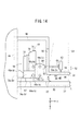
先ず、本実施形態に係るバイオプシ装置(生検装置)10を組み込んだマンモグラフィ装置(放射線画像撮影装置)12の基本的な構成について、図1及び図2を参照しながら説明する。 First, a basic configuration of a mammography apparatus (radiation image capturing apparatus) 12 incorporating a biopsy apparatus (biopsy apparatus) 10 according to the present embodiment will be described with reference to FIGS. 1 and 2.
このマンモグラフィ装置12は、基本的には、立設状態に設置される基台14と、該基台14の略中央部に配設された旋回軸16の先端部に固定されるアーム部材18と、被検体(被写体)20の検査対象物としてのマンモ22に対して放射線24を照射する放射線源26を収容し、アーム部材18の一端部に固定される放射線源収容部28と、マンモ22を透過した放射線24を検出する固体検出器(放射線検出器)30が収容され、アーム部材18の他端部に固定される撮影台32と、撮影台32に対してマンモ22を圧迫して保持する圧迫板34とを備える。また、撮影台32の上面におけるアーム部材18側には、マンモ22の生検部位36から必要な組織を採取するバイオプシハンド部38が配置されている。
The
なお、図1及び図2では、座位の体勢にある被検体20のマンモ22を圧迫板34及び撮影台32により圧迫固定した状態において、マンモ22に対する放射線24の照射と、生検部位36に対する組織の採取とが行われる場合を図示している。また、基台14には、被検体20の撮影部位等の撮影条件や被検体20のID情報等を表示すると共に、必要に応じてこれらの情報を設定可能な表示操作部40が配設される。
1 and 2, in the state where the
放射線源収容部28及び撮影台32を連結するアーム部材18は、旋回軸16を中心として旋回することで、被検体20のマンモ22に対する方向が調整可能に構成される。また、放射線源収容部28は、ヒンジ部42を介してアーム部材18に連結されており、矢印φ方向に撮影台32とは独立に旋回可能に構成される。
The
アーム部材18には、被検体20が対向する矢印Y方向の側部(正面側)に矢印Z方向に沿って溝部44が設けられ、一方で、矢印X方向の両側部には、被検体20が把持するための取手部46a、46bがそれぞれ設けられている。溝部44には、矢印Y方向に延在する圧迫板取付部材48の基端部が挿入され、該基端部は、溝部44内の図示しない取付部と嵌合している。また、圧迫板取付部材48の先端部は、矢印Z方向に屈曲してU字型の圧迫板接続部材50に連結され、圧迫板接続部材50の先端部は、圧迫板34のアーム部材18側に連結されている。
The
従って、圧迫板取付部材48の基端部が前記取付部と嵌合することにより、圧迫板34は、放射線源収容部28と撮影台32との間の所定高さに配設されると共に、前記取付部が溝部44に沿って矢印Z方向に変位することにより、該取付部と一体的に矢印Z方向に変位可能である。また、圧迫板34における被検体20の胸壁52側には、バイオプシハンド部38を用いた組織採取のための開口部54が設けられる。
Accordingly, the
バイオプシハンド部38は、撮影台32のアーム部材18側に載置された生検針移動機構56と、生検針移動機構56の動作により三軸方向(矢印X方向、矢印Y方向及び矢印Z方向)に沿って移動し、及び/又は、マンモ22に向かって傾く矢印θ方向に沿って回動することが可能な生検針64とを有する。この場合、生検針移動機構56から矢印Y方向に沿って進退可能なロッド58a、58bの先端にプレート状の生検針保持部60が取り付けられ、この生検針保持部60に生検針64が装着された生検針装着部62が取り付けられている。
The
なお、生検針64が回動する矢印θ方向は、図2に示すように、Y−Z平面に沿った回動方向であり、一方で、放射線源26を収容する放射線源収容部28が回動する矢印φ方向は、図1に示すように、X−Z平面に沿った回動方向である。従って、生検針64が回動する回転平面としての矢印θ方向に沿ったY−Z平面と、放射線源収容部28(放射線源26)が回動する回転平面としての矢印φ方向に沿ったX−Z平面とは、互いに交差(直交)している。
The arrow θ direction in which the
また、前述したU字型の圧迫板接続部材50の先端部と圧迫板34とが連結されることで、X−Z平面に沿った圧迫板接続部材50と圧迫板34とによる開口が形成される(図1参照)。従って、撮影台32上に配置された生検針移動機構56は、前記開口を介してロッド58a、58b及び生検針保持部60を被検体20の胸壁52に向かって進退させることになる。
Moreover, the opening part by the compression
この場合、生検針64が装着された生検針装着部62は、生検針保持部60が前記開口と胸壁52との間の所定位置(放射線源収容部28や胸壁52との干渉が発生しない位置)に配置されたときに、医師又は技師により生検針保持部60に取り付けられる。
In this case, the biopsy
あるいは、生検針移動機構56をマンモグラフィ装置12に組み込む前、あるいは、組み込んだ際に、生検針保持部60に生検針装着部62を取り付けておくことも可能である。この場合、生検針装着部62及び生検針64は、生検針移動機構56の駆動作用下に前記開口を通過して胸壁52側に進行することになる。
Alternatively, the biopsy
生検針64は、マンモ22の病変部位(例えば、石灰化部分)としての生検部位36の組織(石灰化組織)を吸引して採取する採取部66を有する。生検針64の採取部66は、生検針移動機構56によって、生検針保持部60、生検針装着部62及び生検針64を一体的に圧迫板34の面に沿ったX−Y平面内で移動させると共に矢印Z方向に移動させ、及び/又は、矢印θ方向に回動させることにより、生検部位36の近傍に配置することができる。
The
次に、生検針移動機構56の構成について、図3〜図10を参照しながら説明する。
Next, the configuration of the biopsy
先ず、生検針移動機構56の外観について、図2及び図3を参照しながら説明する。生検針移動機構56は、被検体20からアーム部材18側を視たときに、Z軸を中心として、左右対称の構造となっている。
First, the appearance of the biopsy
すなわち、生検針移動機構56は、ベース67を介して撮影台32に載置され、アーム部材18側の背面には、アーム部材18に当接可能な位置決め部材(取付部)68a、68bと、該位置決め部材68a、68bからアーム部材18側に延在するロッド(取付部)70a、70bとが矢印Y方向に沿って設けられている。これにより、生検針移動機構56のベース67を撮影台32に接触させた状態で、ロッド70a、70bをアーム部材18の図示しない凹部に挿入することにより、アーム部材18と位置決め部材68a、68bとが当接し、この結果、マンモグラフィ装置12における図1及び図2に示す位置に生検針移動機構56が位置決め固定される。
That is, the biopsy
生検針移動機構56の背面側(アーム部材18側)には、位置決め部材68a、68b及びベース67に連結される背面部材72が立設され、背面部材72の矢印X方向の両側部には、矢印Y方向に向かって一部分が湾曲した湾曲部材74a、74bが設けられている。なお、背面部材72の上面における被検体20側は、矢印θ方向に沿って湾曲している。
On the back side (
また、背面部材72の被検体20側には、レバー76が固定され、且つ、矢印θ方向に回動可能な回動ユニット(回動部)78が配置されている。また、回動ユニット78の矢印X方向の両側部には、矢印Y方向に向かって一部分が湾曲した湾曲部材80a、80bが設けられている。さらに、回動ユニット78の矢印Y方向側には、矢印Z方向に移動可能な移動ユニット(移動部)82が設けられている。
Further, on the subject 20 side of the
移動ユニット82の矢印Y方向側には、被検体20に向かって突出すると共に、矢印X方向に沿って形成された溝84に沿い、ロッド58a、58b、生検針保持部60、生検針装着部62及び生検針64を一体的に矢印X方向に移動させるための移動ユニット(移動部)86が設けられている。
On the arrow Y direction side of the moving
なお、湾曲部材74a、74bには軸部88a、88bがそれぞれ取り付けられ、回動ユニット78の両側部にはハンドル90a、90bがそれぞれ取り付けられ、移動ユニット82の両側部にはハンドル92a、92b、94a、94bがそれぞれ取り付けられている。
生検針移動機構56の外観は、上記の通りであり、次に、その内部構成について、図4〜図10を参照しながら説明する。なお、図4〜図10では、説明の容易化のために、一部分のみそれぞれ図示する。
The appearance of the biopsy
先ず、生検針移動機構56の内部構成のうち、矢印θ方向への回動に関わる構成(回動ユニット78の内部構成)について、図4及び図5を参照しながら説明する。
First, of the internal configuration of the biopsy
図4に示すように、生検針移動機構56の内部には、ベース67及び背面部材72に連結する支持部材100が立設し、支持部材100の上面側に設けられた支持部材102には、ロッド等の軸部材104を介してL字状の回動部材106が軸支されている。この場合、レバー76は、回動ユニット78の上面110を貫通する連結部材108を介して回動部材106に連結されている。さらに、回動部材106の矢印Y方向側には、締結部材等の固定部材112、114を介してプレート116が固定されている。
As shown in FIG. 4, a
なお、回動ユニット78の上面110は、矢印θ方向に沿って湾曲する一方で、該上面110に接触する背面部材72の上面118も矢印θ方向に沿って湾曲している。また、軸部材104にはロータリーエンコーダ(角度検出部)120が連結されている。さらに、軸部88a、88bの先端部は、湾曲部材74a、74b及び回動ユニット78を貫通して該回動ユニット78の内部にまで進入し、回動ユニット78の側部には、進入した軸部88a、88bの先端部に対応するように円弧状の溝122が形成されている。
The
前述したように、回動ユニット78には湾曲部材80a、80bや移動ユニット82が設けられ、移動ユニット82には移動ユニット86が設けられ、さらに、移動ユニット86は、ロッド58a、58b、生検針保持部60、生検針装着部62及び生検針64を一体的に矢印X方向に移動させる。
As described above, the turning
従って、図4の状態において、医師又は技師がレバー76を矢印θ方向(図5参照)に引くと、回動部材106が軸部材104を中心として支持部材102に対して回動し、この結果、回動部材106に連結された連結部材108及びレバー76を含む回動ユニット78や、この回動ユニット78に設けられた湾曲部材80a、80b及び移動ユニット82や、移動ユニット82に設けられた移動ユニット86や、移動ユニット86に取り付けられたロッド58a、58b、生検針保持部60、生検針装着部62及び生検針64が、矢印θ方向に沿って一体的に回動する。
Accordingly, when the doctor or engineer pulls the
この場合、溝122が矢印θ方向に対応するように円弧状に形成されているので、医師又は技師によるレバー76の操作に伴って、軸部88a、88bに対する溝122の相対的な位置関係が変化することにより、ベース67、背面部材72、支持部材100、102及び軸部88a、88b(ベース)以外の生検針移動機構56の構成要素を一体的に(全体的に)矢印θ方向に回動させることができる(図5参照)。
In this case, since the
つまり、回動ユニット78に図4に図示された各構成要素を内包させ、あるいは、取り付けることにより、該回動ユニット78の矢印θ方向への回動に起因して、生検針移動機構56を全体的に矢印θ方向に回動させることが可能となる。
That is, the biopsy
また、ロータリーエンコーダ120は、支持部材102に対する回動部材106の回動量を回動角度θとして検出し、検出した回動角度θを外部に出力する。
Further, the
次に、生検針移動機構56の内部構成のうち、矢印Z方向への移動に関わる構成について、図6及び図7を参照しながら説明する。
Next, of the internal configuration of the biopsy
プレート116(図5〜図7参照)の矢印Z方向側(ベース67側)には、取付板130を介してモータ132及びロータリーエンコーダ(変位量検出部)134が取り付けられている。モータ132の回転軸136に取り付けられたギヤ138は、両端部がハンドル90a、90bに連結されたロッド140に設けられたギヤ142と噛合している。
A
すなわち、ロッド140は、回動ユニット78の側部の内方に配置された軸受144a、144b及び回動ユニット78の側部を貫通してハンドル90a、90bに連結されている。また、ロッド140の軸受144a、144b側にはウォーム146a、146bがそれぞれ設けられている。この場合、プレート116におけるウォーム146a、146b近傍に形成された孔148a、148bにロッド150a、150bが貫通し、該ロッド150a、150bの一端部に形成されたウォームホイール152a、152bがウォーム146a、146bにそれぞれ噛合している。
In other words, the
さらに、プレート116から矢印Y方向に離間して、移動ユニット82内には、該プレート116と平行にプレート156が配置されている。プレート156には、矢印Z方向に沿ってラック158a、158bが設けられ、各ラック158a、158bは、ロッド150a、150bの他端部側に設けられたピニオン154a、154bと噛合している。
Further, a
ここで、モータ132の駆動作用下に回転軸136が回転すると、ギヤ138、142を介してロッド140も回転する。ウォーム146a、146bに噛合するウォームホイール152a、152bは、ロッド140を中心とする回転(矢印X方向を中心とする回転)を、矢印Y方向を中心とした回転に変換してロッド150a、150bをそれぞれ回転させる。従って、ロッド150a、150bに設けられたピニオン154a、154bに噛合しているラック158a、158bは、ロッド150a、150bを中心とする回転を矢印Z方向に沿った直進運動に変換し、この結果、ラック158a、158bが配置されたプレート156は、矢印Z方向に移動することが可能となる。
Here, when the
この場合、プレート156は、図7及び図8に示すように、プレート156に配置されたモータ162、192の回転軸166、196、ギヤ168、170、174、198、202を介して、移動ユニット82の側部を矢印X方向に沿って貫通するロッド172、200に連結されている。また、プレート156は、図示しない取付部材を介して移動ユニット82に連結されている。さらに、前述したように、移動ユニット82に設けられた移動ユニット86は、ロッド58a、58b、生検針保持部60、生検針装着部62及び生検針64を一体的に矢印X方向に移動させる。
In this case, as shown in FIGS. 7 and 8, the
従って、プレート156が矢印Z方向に移動することにより、移動ユニット82及び移動ユニット86や、ロッド58a、58b、生検針保持部60、生検針装着部62及び生検針64も一体的に矢印Z方向に移動する。
Therefore, when the
つまり、移動ユニット82に図6〜図8に図示された各構成要素を内包させ、あるいは、取り付けることにより、該移動ユニット82の矢印Z方向への移動に起因して、移動ユニット82よりも生検針64側の各構成要素を一体的に矢印Z方向に移動(変位)させることが可能となる。
That is, when the moving
なお、ロッド140の両端部にはハンドル90a、90bが取り付けられているので、医師又は技師がハンドル90a、90bを回してロッド140を回転させることに起因して、プレート156や移動ユニット82を矢印Z方向に変位させることも可能である。
Since the
また、ロータリーエンコーダ134は、回転軸136の回転量を検出し、検出した回転量を外部に出力する。なお、回転軸136の回転に起因してプレート156や移動ユニット82が矢印Z方向に変位するので、前記回転量は、矢印Z方向に沿ったプレート156や移動ユニット82の変位量に応じた回転量とみなすことができる。
The
次に、生検針移動機構56の内部構成のうち、矢印X方向への移動に関わる構成について、図7〜図9を参照しながら説明する。
Next, of the internal configuration of the biopsy
プレート156における図8の左側には、取付板160を介してモータ162及びロータリーエンコーダ164が取り付けられている。モータ162の回転軸166に取り付けられたギヤ168は、ギヤ170を介して、両端部がハンドル92a、92bに連結されたロッド172に設けられるギヤ174と噛合している。
A
すなわち、ロッド172は、移動ユニット82の側部の内方に配置された軸受176a、176b及び移動ユニット82の側部を貫通してハンドル92a、92bに連結されている。また、ロッド172におけるギヤ174と軸受176bとの間には、ねじ部178が形成され、ねじ部178に対してスライド部材180が摺動自在に取り付けられている。
That is, the
ここで、モータ162の駆動作用下に回転軸166が回転すると、ギヤ168、170、174を介してロッド172も回転する。従って、ねじ部178に噛合するスライド部材180は、ロッド172を中心とした回転を矢印X方向への直進運動に変換して、該矢印X方向に沿って摺動する。
Here, when the
この場合、スライド部材180は、U字状の連結部材220の下端側に取り付けられ、上端側にはプレート238及び支持部材246a、246bを介してロッド58a、58bが支持されている(図10参照)。また、ロッド58a、58bは、矢印X方向に沿って形成された溝84を介して外部に延在している。従って、スライド部材180が矢印X方向に移動することにより、ロッド58a、58b、生検針保持部60、生検針装着部62及び生検針64も溝84に沿って一体的に矢印X方向に移動する。
In this case, the
つまり、移動ユニット82に図7〜図10に図示された各構成要素を内包させ、あるいは、取り付けることにより、スライド部材180の矢印X方向への移動に起因して、連結部材220と生検針64との間に配置された各構成要素を一体的に矢印X方向に移動(変位)させることが可能となる。
That is, the connecting
なお、ロッド172の両端部にはハンドル92a、92bが取り付けられているので、医師又は技師がハンドル92a、92bを回してロッド172を回転させることに起因して、スライド部材180を矢印X方向に変位させることも可能である。
Since the
また、ロータリーエンコーダ164は、回転軸166の回転量を検出し、検出した回転量を外部に出力する。なお、回転軸166の回転に起因してスライド部材180が矢印X方向に変位するので、前記回転量は、矢印X方向に沿ったスライド部材180の変位量に応じた回転量とみなすことができる。
The
次に、生検針移動機構56の内部構成のうち、矢印Y方向への移動に関わる構成について、図7〜図10を参照しながら説明する。
Next, of the internal configuration of the biopsy
プレート156における図8の右側には、取付板190を介してモータ192及びロータリーエンコーダ194が取り付けられている。モータ192の回転軸196に取り付けられたギヤ198は、両端部がハンドル94a、94bに連結されたロッド200に設けられたギヤ202と噛合している。
A
すなわち、ロッド200は、移動ユニット82の側部の内方に配置された軸受204a、204b及び移動ユニット82の側部を貫通してハンドル94a、94bに連結されている。また、ロッド200の中央部には、円筒状のスペーサ210を介してウォーム208が配置されている。
In other words, the
前述したように、スライド部材180は、矢印Z方向に延在する連結部材220の下端部に配置されている。具体的に、連結部材220の下端部には、ロッド172よりも低位置にプレート222が設けられ、プレート222上にスライド部材180が固定されている。また、スライド部材180の矢印X方向の側部は、連結部材220の下端部を構成する側板224a、224bに接触し、該側板224a、224bには、ロッド172を貫通させるための孔226a、226bが形成されている。
As described above, the
一方、連結部材220の上端部には、側板224a、224bと対向するように側板228a、228bが設けられ、該側板228a、228bには、ロッド200が貫通する軸受230a、230bがそれぞれ取り付けられている。この場合、ウォーム208は、軸受230a、230b間に配置されている。
On the other hand,
なお、スペーサ210は、スライド部材180の矢印X方向への変位に伴って連結部材220が矢印X方向に変位したときに、当該変位に起因した力を受け、ロッド200に沿って摺動可能である一方、ロッド200が回転したときには該ロッド200の回転をウォーム208に伝達する。
The
つまり、スペーサ210は、ロッド200が回転したときに、ロッド200の回転をウォーム208に伝達して該ウォーム208を回転させ、一方で、スライド部材180及び連結部材220が矢印X方向に移動したときに、該ウォーム208と共に矢印X方向に変位する。
That is, when the
ウォーム208は、矢印Z方向に延在するロッド234の一端部側に設けられたウォームホイール232と噛合する。ロッド234は、側板228a、228bの上部側を橋架するプレート238を貫通し、貫通したロッド234の他端部側にはギヤ236が形成されている。ギヤ236は、ギヤ240、242を介してロッド58bに形成されたラック部244と噛合している。また、ロッド58a、58bは、プレート238上に設けられた支持部材246a、246bを貫通し、且つ、溝84(図3参照)を通過して矢印Y方向に延在している。
The
ここで、モータ192の駆動作用下に回転軸196が回転すると、ギヤ198、202を介してロッド200も回転する。従って、ロッド200の軸方向を中心とした回転(矢印X方向を中心とした回転)は、スペーサ210を介してウォーム208に伝達される。ウォームホイール232は、ウォーム208の矢印X方向を中心とした回転を矢印Z方向を中心とした回転に変換して、ロッド234を回転させる。ロッド234の回転は、ギヤ236、240、242を介してラック部244に伝達され、ラック部244は、ロッド234の回転を矢印Y方向に沿った直進運動に変換してロッド58bを変位させる。この結果、ロッド58a、58b、生検針保持部60、生検針装着部62及び生検針64も一体的に矢印Y方向に移動する。
Here, when the
つまり、移動ユニット82、86に図7〜図10に図示された各構成要素を内包させ、あるいは、取り付けることにより、ロッド200の回転に起因して、ロッド58a、58bから生検針64側の各構成要素を一体的に矢印Y方向に移動(変位)させることが可能となる。
That is, each component on the
なお、ロッド200の両端部にはハンドル94a、94bが取り付けられているので、医師又は技師がハンドル94a、94bを回してロッド200を回転させることに起因して、ラック部244を矢印Y方向に変位させることも可能である。
Since the
また、ロータリーエンコーダ194は、回転軸196の回転量を検出し、検出した回転量を外部に出力する。なお、回転軸196の回転に起因してラック部244部が矢印Y方向に変位するので、前記回転量は、矢印Y方向に沿ったラック部244の変位量に応じた回転量とみなすことができる。
The
以上が生検針移動機構56の構成に関する説明である。
The above is the description regarding the configuration of the biopsy
なお、以下の説明では、特に断りが無い限り、生検針移動機構56による生検針64等の矢印X方向、矢印Y方向及び矢印Z方向への移動、並びに、生検針64等の矢印θ方向への回動は、基本的には、上記の図3〜図10に従って行われるものとする。
In the following description, unless otherwise specified, the biopsy
次に、マンモグラフィ装置12によるマンモ22の撮影方法(図11及び図12参照)と、撮影後に生検針移動機構56を動作させることにより行われるマンモ22への生検針64の刺入方法(図13A〜図16C参照)とについて説明する。
Next, an imaging method of the
マンモグラフィ装置12では、固体検出器30の垂直軸(中心軸250a)に配置された放射線源26からマンモ22に対して放射線24aを照射するスカウト撮影(図11参照)、あるいは、中心軸250aに対して斜めに配置された放射線源26から中心軸250b、250cに沿いマンモ22に対して放射線24b、24cを照射するステレオ撮影(図12参照)が行われる。固体検出器30は、スカウト撮影又はステレオ撮影によりマンモ22を透過した放射線24a〜24cを検出して放射線画像に変換する。
In the
なお、図11及び図12では、一例として、各中心軸250a〜250cが生検部位36を通る場合での放射線24a〜24cの照射を図示している。
In addition, in FIG.11 and FIG.12, irradiation of the
図11のスカウト撮影において、固体検出器30に対する放射線源26の撮影角度φはφ=0°であり、このスカウト撮影での放射線源26の位置をA位置とする。また、図12のステレオ撮影において、所定の撮影角度を+φ1、−φ1(B位置、C位置)とする。この場合、マンモグラフィ装置12では、A位置、B位置及びC位置との間の放射線源26の移動を、ヒンジ部42(図1参照)を中心として放射線源収容部28を回動させることにより行う。
In the scout imaging of FIG. 11, the imaging angle φ of the
このような撮影を行った後に、生検針移動機構56の動作に起因したマンモ22への生検針64の刺入が行われる。
After performing such imaging, the
図13A〜図13Cは、従来の刺入における問題点を説明するための説明図である。なお、図13A〜図13Cにおいて、本実施形態における構成要素と対応する構成要素については、同じ参照符号を付けて説明する。 13A to 13C are explanatory diagrams for explaining problems in conventional insertion. In FIG. 13A to FIG. 13C, components corresponding to the components in the present embodiment will be described with the same reference numerals.
マンモ22に対して生検針64を刺入させる方法としては、マンモ22の圧迫方向(矢印Z方向)に対して生検針64を傾けた状態で該生検針64をマンモ22に刺入させる方法(図13A及び図13Bに示す斜め穿刺)と、前記圧迫方向に沿って生検針64をマンモ22に刺入させる方法(図13Cに示す垂直穿刺)とがあり、市場に流通している生検装置(従来の生検装置)は、斜め穿刺又は垂直穿刺のいずれか一方の方法に従って生検部位36の組織の採取を行っている。
As a method of inserting the
しかしながら、斜め穿刺用の生検装置では、マンモ22に対して斜めに生検針64を刺入するので、垂直穿刺の場合と比較して、マンモ22の厚みに関わりなく、開口部54の外周部分が組織を採取することができない領域252、254となるおそれがある(図13A及び図13Bの斜線部分)。この領域252、254内の組織を採取するためには、マンモ22を圧迫状態から一旦開放した後に、平面視で、領域252、254が開口部54の中央部に来るように位置決めしてからマンモ22を再度圧迫し、斜め穿刺を改めて行う必要がある。従って、斜め穿刺の場合には、領域252、254に存在し且つ採取したい組織の数に応じて、マンモ22の位置決め→圧迫→撮影→斜め穿刺→組織の採取→開放の工程を繰り返し何度も行う必要があるので、被検体20を検査に拘束させる時間が長くなると共に、該被検体20に対する放射線24の被爆量が増大する。
However, in the biopsy device for oblique puncture, since the
なお、斜め穿刺の場合では、生検針64を斜めにした状態でマンモ22に該生検針64を刺入するので、比較的薄い厚みのマンモ22であっても、撮影台32側に存在する組織を採取することが可能である。
In the case of oblique puncture, since the
垂直穿刺用の生検装置では、比較的厚みのあるマンモ22中の生検部位36に対しては、組織の一部を採取することは可能であるが、一方で、比較的薄い厚みのマンモ22中の生検部位36に対しては、採取部66の位置を生検部位36に合わせたときに、生検針64の先端部が該マンモ22を突き抜けてしまうおそれがある(図13C参照)。従って、垂直穿刺では、薄い厚みのマンモ22中、撮影台32側に存在する組織を採取することが困難である。また、圧迫板34や撮影台32に沿った方向(平面方向)に広がって存在する組織についても迅速に採取することができない。
In the biopsy device for vertical puncture, it is possible to extract a part of the tissue from the
これに対して、本実施形態に係るバイオプシ装置10では、図14に示すように、生検針移動機構56は、比較的厚みのあるマンモ22に対しては、図3〜図10で説明した構成によって、三軸方向(矢印X方向、矢印Y方向及び矢印Z方向)に沿って生検針64を移動させる垂直穿刺を行うことにより生検部位36の組織を採取する。従って、図16A及び図16Bに示すように、比較的厚みのあるマンモ22において、領域252、254にまで生検針64の採取部66を移動させることが可能となる。
On the other hand, in the
一方、図15に示すように、生検針移動機構56は、比較的薄い厚みのマンモ22に対しては、図3〜図10で説明した構成によって、矢印θ方向に沿って生検針64を回動させる斜め穿刺を行うことにより生検部位36の組織を採取する。従って、図16Cに示すように、比較的薄い厚みのマンモ22において、該マンモ22から生検針64が突き抜けることなく組織の採取を行うことが可能となる。
On the other hand, as shown in FIG. 15, the biopsy
なお、斜め穿刺の場合には、垂直穿刺を併用して、生検針64等を三軸方向に移動させつつ、矢印θ方向に回動させてもよいことは勿論である。
In the case of oblique puncture, it is needless to say that the
図17は、マンモグラフィ装置12の構成ブロック図である。
FIG. 17 is a configuration block diagram of the
マンモグラフィ装置12は、撮影条件設定部260、放射線源駆動制御部262、生検針位置情報算出部264、圧迫板駆動制御部266、圧迫板位置情報算出部268、検出器制御部270、画像情報記憶部272、CAD(Computer Aided Diagnosis)処理部274、表示部276、生検部位選択部278、生検部位位置情報算出部280及び移動量算出部282をさらに有する。
The
ここで、マンモグラフィ装置12のうち、前述したバイオプシハンド部38と、開口部54、生検針位置情報算出部264、生検部位選択部278、生検部位位置情報算出部280及び移動量算出部282との構成要素によりバイオプシ装置10が構成される。すなわち、マンモグラフィ装置12にこれらの構成要素を有するバイオプシ装置10を組み込むことにより、生検部位36の組織の一部を採取することが可能となる。
Here, in the
撮影条件設定部260は、管電流、管電圧、放射線24の照射線量、照射時間、スカウト撮影及びステレオ撮影の撮影方法(図11及び図12に示す撮影方法)、撮影順序等の撮影条件を設定する。放射線源駆動制御部262は、前記撮影条件に従って放射線源26を駆動制御する。
The imaging
生検針移動機構56により生検針64等を所定位置に移動及び/又は回動させたときに、各ロータリーエンコーダ120、134、164、194がそれぞれ検出した各回転量は、生検針位置情報算出部264に出力される。
When the
圧迫板駆動制御部266は、圧迫板34を矢印Z方向に移動させる。検出器制御部270は、固体検出器30を制御して、該固体検出器30で放射線24から変換された放射線画像を画像情報記憶部272に記憶する。図11のスカウト撮影の場合には1つの撮影角度での1枚の放射線画像が画像情報記憶部272に記憶され、ステレオ撮影の場合には2つの撮影角度(ステレオ角度)での2枚の放射線画像が画像情報記憶部272に記憶される。なお、画像情報記憶部272に放射線画像を記憶する際に、撮影条件設定部260に設定された撮影条件を共に記憶してもよいことは勿論である。
The compression plate
CAD処理部274は、画像情報記憶部272に記憶された放射線画像に対する画像処理を行って表示部276及び表示操作部40に表示させる。
The
生検部位選択部278は、マウス等のポインティングデバイスであり、表示部276及び/又は表示操作部40の表示内容(ステレオ撮影により得られた2枚の放射線画像)を視た医師又は技師は、前記ポインティングデバイスを用いて、2枚の放射線画像中の(複数の)生検部位36の中から、組織を採取したい生検部位36を選択することが可能である。なお、生検部位選択部278による生検部位36の選択では、2枚の放射線画像の一方の画像中の生検部位36を選択すると共に、該一方の画像中の生検部位36に対応する他方の画像中の生検部位36も選択する。
The biopsy
生検部位位置情報算出部280は、生検部位選択部278により選択された2枚の放射線画像中の生検部位36の位置に基づいて、該生検部位36の三次元位置を算出する。なお、生検部位36の三次元位置については、ステレオ撮影における公知の三次元位置の算出方法に基づき算出することが可能である。
The biopsy site position
生検針位置情報算出部264は、生検部位36の組織の一部を採取する場合に、各ロータリーエンコーダ120、134、164、194からの各回転量に基づいて、組織を採取する前の生検針64の先端部の三次元位置を算出する。
The biopsy needle position
生検針移動機構56が全体的に矢印θ方向に回動しておらず、三軸方向にのみ生検針64等を移動させている場合、生検針位置情報算出部264は、三軸方向の変位量に応じた各ロータリーエンコーダ134、164、194からの各回転量に基づいて、生検針64の先端部の三次元位置を算出する。
When the biopsy
一方、生検針移動機構56が全体的に矢印θ方向に回動することにより、ロータリーエンコーダ120が生検針位置情報算出部264に回転量を出力してきた場合に、生検針位置情報算出部264は、先ず、矢印θ方向への回動がないときの生検針64の先端部の三次元位置を算出し、次に、ロータリーエンコーダ120からの回転量に基づいて、矢印θ方向に生検針64を回動させたときの該生検針64の先端部の三次元位置を算出する。
On the other hand, when the
具体的に、回動前(回動角度θがX−Z平面に沿った図4及び図14に示すθ=0°の状態)の生検針64の先端部の三次元位置を(X1、Y1、Z1)とし、回動後(図5及び図15に示す回動角度θの状態)の生検針64の先端部の三次元位置を(X2、Y2、Z2)とした場合、生検針64の矢印θ方向への回動は、Y−Z平面に沿った回動であり、従って、X方向への回動は発生しないので、X1=X2となる。従って、Y2及びZ2は、X1、Z1及び回動角度θを用いると、下記の(1)式及び(2)式で表わされる。
Y2=Y1×cosθ−Z1×sinθ (1)
Z2=Y1×sinθ+Z1×cosθ (2)
Specifically, the three-dimensional position of the distal end portion of the
Y2 = Y1 × cos θ−Z1 × sin θ (1)
Z2 = Y1 × sin θ + Z1 × cos θ (2)
すなわち、生検針位置情報算出部264は、公知の二次元の座標変換(生検針64が回動するY−Z平面における座標変換)に基づく(1)式及び(2)式を用いて、回動前の生検針64の先端部の三次元位置(X1、Y1、Z1)から、回動後の生検針64の先端部の三次元位置(X2、Y2、Z2)を求める。
That is, the biopsy needle position
圧迫板位置情報算出部268は、圧迫板駆動制御部266によって移動する圧迫板34の撮影台32に対する位置を算出する。圧迫板34は、撮影台32に対してマンモ22を圧迫して保持するので、圧迫板34の位置情報は、圧迫時のマンモ22の厚み情報を示していることになる。
The compression plate position
移動量算出部282は、生検部位位置情報算出部280により算出された生検部位36の三次元位置と、生検針位置情報算出部264により算出された生検針64の先端部の三次元位置と、圧迫板位置情報算出部268が算出した圧迫板34の位置(マンモ22の厚み)とに基づいて、斜め穿刺又は垂直穿刺のいずれの方法により生検針64をマンモ22に刺入すべきかを決定すると共に、決定した穿刺方法を実施するときの生検部位36に対する生検針64の移動量を算出する。
The movement
具体的に、矢印θ方向への生検針64の回動がない場合(図4及び図14参照)、移動量算出部282は、生検部位位置情報算出部280が算出した生検部位36の三次元位置(Xt、Yt、Zt)と、生検針位置情報算出部264が算出した生検針64の先端部の三次元位置(X1、Y1、Z1)との差(ΔX1、ΔY1、ΔZ1)=(Xt−X1、Yt−Y1、Zt−Z1)を、生検針64の移動量(ΔX1、ΔY1、ΔZ1)として算出する。
Specifically, when there is no rotation of the
一方、矢印θ方向に生検針64が回動した場合(図5及び図15参照)、移動量算出部282は、先ず、生検部位位置情報算出部280が算出した生検部位36の三次元位置(Xt、Yt、Zt)と、生検針位置情報算出部264が算出した、回動後の生検針64の先端部の三次元位置(X2、Y2、Z2)との差(ΔX2、ΔY2、ΔZ2)=(Xt−X2、Yt−Y2、Zt−Z2)を算出する。
On the other hand, when the
この場合、(ΔX2、ΔY2、ΔZ2)は、X−Y−Z座標系で視たときの、生検部位36に対する、回動後の生検針64の移動量を表わしている。また、前述したようにX1=X2であることから、ΔX1=ΔX2となる。
In this case, (ΔX2, ΔY2, ΔZ2) represents the amount of movement of the
そこで、移動量算出部282は、X−Y−Z座標系を回動角度θだけ回動させたX´−Y´−Z´座標系(図示せず)で視たときの、生検部位36に対する、回動後の生検針64の移動量(ΔX´、ΔY´、ΔZ´)を求める。
Therefore, the movement
すなわち、前述したように、生検針64の矢印θ方向への回動は、Y−Z平面に沿った回動であり、X方向への回動は発生しないので、ΔX1=ΔX2=ΔX´となる。従って、ΔY´及びΔZ´は、ΔY2、ΔZ2及び回動角度θを用いると、下記の(3)式及び(4)式で表わされる。
ΔY´=ΔY2×cosθ−ΔZ2×sinθ (3)
ΔZ´=ΔY2×sinθ+ΔZ2×cosθ (4)
That is, as described above, the rotation of the
ΔY ′ = ΔY2 × cos θ−ΔZ2 × sin θ (3)
ΔZ ′ = ΔY2 × sin θ + ΔZ2 × cos θ (4)
つまり、移動量算出部282は、公知の二次元の座標変換(生検針64が回動するY−Z平面における座標変換)に基づく(3)式及び(4)式を用いて、回動後の生検針64の移動量を求める。
That is, the movement
これにより、生検針移動機構56は、移動量算出部282が決定した穿刺方法(斜め穿刺又は垂直穿刺)及び算出した生検針64の移動量に従って、該生検針64を移動させ、組織の採取を行わせることができる。
Thereby, the biopsy
また、生検針移動機構56が生検針64を移動させ、及び/又は、回動させている最中においても、各ロータリーエンコーダ120、134、164、194は、回転量を検出して生検針位置情報算出部264に出力することが可能である。この場合、生検針位置情報算出部264は、各回転量に基づいて、現時点での生検針64の先端部の三次元位置(実際の三次元位置)を算出する。従って、移動量算出部282は、生検針移動機構56に指示した移動量と、生検針位置情報算出部264が算出した現時点での三次元位置(実際の三次元位置)に基づく実際の移動量とを比較して、これらの移動量の差が許容範囲外であれば、生検針移動機構56が指示に従って生検針64を移動させていないことを示す判断結果(警告)を表示部276や表示操作部40を介して医師や技師に通知する。
Further, even while the biopsy
本実施形態に係るバイオプシ装置10及びマンモグラフィ装置12の構成は、上述した通りであり、次に、該バイオプシ装置10及びマンモグラフィ装置12の動作について、図18のフローチャートを参照しながら説明する。
The configurations of the
撮影に先立ち、撮影条件設定部260(図17参照)に、マンモ22に応じた管電流、管電圧、放射線24の照射線量、照射時間、撮影方法、撮影順序等の撮影条件が設定される。また、マンモグラフィ装置12にバイオプシハンド部38を組み込んで撮影台32上に位置決め固定する。
Prior to imaging, imaging conditions such as a tube current, a tube voltage, an irradiation dose of
そして、ステップS1において、医師又は技師は、被検体20のマンモ22のポジショニングを行う。すなわち、マンモ22を撮影台32の所定位置(開口部54に対向する位置)に配置した後、圧迫板駆動制御部266により圧迫板34を撮影台32に向かって矢印Z方向に移動させ、マンモ22を圧迫してポジショニングを行う。
In step S1, the doctor or engineer positions the
これにより、マンモ22は、撮影台32及び圧迫板34により圧迫固定される。圧迫板位置情報算出部268は、圧迫板34の撮影台32に対する位置情報を算出して移動量算出部282及び生検針移動機構56に出力する。
As a result, the
生検針移動機構56(図3〜図10参照)は、圧迫板位置情報算出部268からの圧迫板34の位置情報の入力があれば、マンモ22が圧迫されたものと判断し、各モータ132、162、192を駆動させる。この結果、生検針装着部62が未装着の生検針保持部60は、各モータ132、162、192の駆動に起因したロッド58a、58bの矢印Y方向への変位によって、圧迫板接続部材50と圧迫板34との間に形成された開口を通過し、胸壁52側の所定位置、具体的には、生検針保持部60に対する生検針装着部62の際に放射線源収容部28や胸壁52との干渉が発生しないような位置にまで進行する。生検針保持部60が前記位置にまで進行したときに、医師又は技師は、生検針64が装着された生検針装着部62を生検針保持部60に取り付ける。
The biopsy needle moving mechanism 56 (see FIGS. 3 to 10) determines that the
なお、各ロータリーエンコーダ134、164、194は、前記位置にまで生検針保持部60が移動したときの回転軸136、166、196の回転量をそれぞれ検出して生検針位置情報算出部264に出力する。従って、生検針装着部62が生検針保持部60に取り付けられた時点で、生検針位置情報算出部264は、前記各回転量に基づいて、生検針64の三次元位置を算出することが可能となる。
Each
このようにして、撮影準備が完了した後に、マンモグラフィ装置12は、放射線源26を駆動して、マンモ22に対するスカウト撮影を行う(ステップS2)。
Thus, after the preparation for imaging is completed, the
この場合、ヒンジ部42(図1参照)を中心として放射線源収容部28を回動させて放射線源26がA位置(図11参照)に移動された後に、医師又は技師が図示しない曝射スイッチを投入すると、放射線源駆動制御部262は、撮影条件設定部260からのスカウト撮影の撮影条件に従って、A位置(0°)に配置された放射線源26を駆動制御する。
In this case, after the radiation
これにより、放射線源26から出力された放射線24aは、マンモ22に照射され、マンモ22を透過した放射線24aは、固体検出器30によって放射線画像として検出される。検出器制御部270は、固体検出器30を制御して1枚の放射線画像を取得し、取得した1枚の放射線画像と前記撮影条件とを共に画像情報記憶部272に一旦記憶させる。CAD処理部274は、画像情報記憶部272に記憶された放射線画像に対する画像処理を行って表示部276及び表示操作部40に表示させる。これにより、生検部位36を含むマンモ22が放射線画像の撮影範囲内に入っていることを確認することができる。
Thereby, the
次のステップS3において、放射線源26を再度駆動し、マンモ22のステレオ撮影を行う。
In the next step S <b> 3, the
この場合も、マンモグラフィ装置12は、ヒンジ部42(図1参照)を中心として放射線源収容部28を回動させ、例えば、図12に示すB位置に放射線源26を配置する。次に、医師又は技師が曝射スイッチを投入すると、放射線源駆動制御部262は、撮影条件設定部260からのステレオ撮影の撮影条件に従って、B位置(+φ1)に配置された放射線源26を駆動制御する。
Also in this case, the
これにより、B位置の放射線源26から出力された放射線24bは、マンモ22に照射され、マンモ22を透過した放射線24bは、固体検出器30によって1枚目の放射線画像として検出される。検出器制御部270は、固体検出器30を制御して1枚の放射線画像を取得し、取得した1枚目の放射線画像を前記撮影条件と共に画像情報記憶部272に一旦記憶させる。
As a result, the
B位置での1枚目の放射線画像の撮影が完了した時点で、マンモグラフィ装置12は、今度は、図12のC位置に放射線源26を移動させ、上述したB位置での撮影と同様にして、C位置での2枚目の放射線画像の撮影を実行する。
When the first radiographic image capturing at the B position is completed, the
C位置での撮影により2枚目の放射線画像が取得され、取得した2枚目の放射線画像が撮影条件と共に画像情報記憶部272に一旦記憶させた後に、CAD処理部274は、画像情報記憶部272に記憶された2枚の放射線画像に対する画像処理を行って表示部276及び表示操作部40に表示させる。
After the second radiographic image is acquired by imaging at the C position, and the acquired second radiographic image is temporarily stored in the image
次のステップS4において、医師又は技師は、表示部276又は表示操作部40の表示内容を視て、マウス等のポインティングデバイスである生検部位選択部278を用い、表示部276及び/又は表示操作部40に表示された2枚の放射線画像から、(複数の)生検部位36のうち、組織を採取したい生検部位36を選択する。これにより、生検部位位置情報算出部280は、選択された生検部位36の三次元位置を算出し、算出した三次元位置を表示部276及び表示操作部40に表示させる。
In the next step S4, the doctor or engineer looks at the display content of the
次のステップS5において、医師又は技師は、マンモ22に生検針64を刺入する前にマンモ22に対する消毒及び局所麻酔を行う。
In the next step S <b> 5, the doctor or engineer performs disinfection and local anesthesia for the
ステップS5の局所麻酔によって生検部位36の位置が移動する場合があるので、ステップS6においてステレオ撮影を再度行う。
Since the position of the
次のステップS7において、マンモ22表面における生検針64の刺入位置をメスで切開し、その後、切開位置に生検針64を刺入する。
In the next step S7, the insertion position of the
この場合、ステップS6のステレオ撮影により得られた2枚の放射線画像を表示部276及び表示操作部40に表示させ、医師又は技師は、表示部276又は表示操作部40の表示内容を視て、生検部位選択部278を用い、表示部276及び/又は表示操作部40に表示された2枚の放射線画像から、組織を採取したい生検部位36を再度選択する。これにより、生検部位位置情報算出部280は、選択された生検部位36の三次元位置を再度算出する。
In this case, the two radiation images obtained by the stereo imaging in step S6 are displayed on the
一方、生検針位置情報算出部264は、ステップS1において、既に生検針64の現時点での先端部の三次元位置を算出しているので、算出した三次元位置を移動量算出部282に出力する。
On the other hand, since the biopsy needle position
移動量算出部282は、生検部位位置情報算出部280により算出された生検部位36の三次元位置と、生検針位置情報算出部264により算出された生検針64の先端部の三次元位置と、圧迫板位置情報算出部268が算出した圧迫板34の位置とに基づいて、前記切開位置までの生検針64の移動量を算出し、算出した前記移動量を生検針移動機構56に出力する。これにより、生検針移動機構56は、移動量算出部282が算出した生検針64の移動量に従って、生検針64の先端部を前記切開位置にまで移動させる。
The movement
次のステップS8において、生検部位36に対して生検針64の刺入方向が一致しているか否かを確認するために、ステップS6と同様のステレオ撮影を再度行う。
In the next step S8, in order to confirm whether or not the insertion direction of the
ステップS8でのステレオ撮影により得られた2枚の放射線画像が表示部276及び表示操作部40に表示されたときに、医師又は技師は、生検部位選択部278を操作して、ステップS4、S7と同様に、2枚の放射線画像中、組織を採取したい生検部位36を再度選択する。生検部位位置情報算出部280は、選択された生検部位36の三次元位置を算出し、算出した三次元位置を表示部276及び表示操作部40に再度表示させると共に、移動量算出部282に出力する。
When the two radiographic images obtained by stereo imaging in step S8 are displayed on the
ステップS9において、各ロータリーエンコーダ120、134、164、194は、前記切開位置までの移動に応じた回転量をそれぞれ検出して生検針位置情報算出部264に出力し、生検針位置情報算出部264は、各回転量に基づいて生検針64の先端部の三次元位置を算出し、算出した三次元位置を移動量算出部282に出力する。移動量算出部282は、生検部位36の三次元位置と、生検針位置情報算出部264で算出された生検針64の先端部の三次元位置と、圧迫板位置情報算出部268で算出された圧迫板34の位置情報とに基づいて、生検針64の穿刺方法を決定すると共に、生検部位36に対する生検針64の移動量を算出し、前記穿刺方法及び前記移動量を生検針移動機構56に出力する。
In step S9, the rotary encoders 120,134,164,194, the incision position rotational amount corresponding to the movement in 置Ma were detected respectively output to the biopsy needle
これにより、生検針移動機構56は、移動量算出部282が決定した穿刺方法(斜め穿刺又は垂直穿刺)及び算出した移動量に従って、生検針64の採取部66を生検部位36にまで移動させることができる。
Thereby, the biopsy
ステップS10において、生検部位36の位置と採取部66の位置及び方向とが一致しているか否かを確認するために、ステップS6、S8と同様のステレオ撮影を再度行う。
In step S10, stereo imaging similar to steps S6 and S8 is performed again in order to confirm whether the position of the
ステップS10でのステレオ撮影により得られた2枚の放射線画像が表示部276及び表示操作部40に表示されたときに、医師又は技師は、生検部位36の位置と採取部66の位置及び方向とが一致しているか否かを容易に確認することができる。
When the two radiographic images obtained by the stereo imaging in step S10 are displayed on the
次のステップS11において、生検針64による生検部位36に対する吸引処理が開始され、組織が採取される。その後、ステップS12において、採取した組織は、図示しない検査装置により検査される(例えば、前記組織の石灰化の有無の検査)。
In the next step S11, suction processing for the
次に、ステップS13において、生検部位36中の組織が採取されたことを確認するために、ステップS6、S8、S10と同様のステレオ撮影を行う。
Next, in step S13, in order to confirm that the tissue in the
ステップS13でのステレオ撮影により得られた2枚の放射線画像が表示部276及び表示操作部40に表示されたときに、医師又は技師は、生検部位36中の組織が採取されているか否かを容易に確認することができる。
When the two radiographic images obtained by the stereo imaging in step S13 are displayed on the
その後、生検針移動機構56は、生検針64をステップS9における移動方向とは逆方向に移動させることにより、生検針64がマンモ22から抜き取られ、作業が終了する(ステップS14)。
Thereafter, the biopsy
なお、生検部位36の組織を全て採取した場合には、後日、生検部位36の位置を確認しようとしたときに分からない場合がある。そこで、このような場合には、ステップS14に先立ち、生検針64の採取部66を介して生検部位36にステンレス製のマーカを挿入し(ステップS15)、その後、マーカが挿入されたことを確認するために、ステップS2と同様のスカウト撮影を行う(ステップS16)。これにより、表示部276及び表示操作部40には、前記スカウト撮影により得られた1枚の放射線画像が表示されて、医師又は技師は、生検部位36中にマーカが挿入されたことを容易に確認することができる。マーカの挿入を確認した後に、ステップS14の処理が行われる。
In addition, when all the tissues of the
以上説明したように、本実施形態に係るバイオプシ装置10及び該バイオプシ装置10を組み込んだマンモグラフィ装置12によれば、生検部位36に対する生検針64の移動量に基づいて、三軸方向(矢印X方向、矢印Y方向及び矢印Z方向)に沿って生検針64を移動させ、及び/又は、マンモ22に向かって傾くように矢印θ方向に生検針64を回動させることにより、マンモ22の厚みに応じた適切な穿刺方法により生検部位36の組織を採取することが可能となる。
As described above, according to the
すなわち、比較的厚みのあるマンモ22については、生検針64を三軸方向に沿って生検針64を移動させる穿刺方法(垂直穿刺)により生検部位36の組織を採取すればよい。一方、比較的薄い厚みのマンモ22については、マンモ22に向かって生検針64を傾けるように回動させる穿刺方法(斜め穿刺)により生検部位36の組織を採取すればよい。
That is, for the relatively
このように、垂直穿刺及び斜め穿刺の利点を活かしながら生検針64を移動させ、及び/又は、回動させて生検部位36の組織の採取を行うので、マンモ22の厚みに関わりなく、該組織の採取を確実に且つ効率よく行うことが可能となる。また、マンモ22の状況に応じて垂直穿刺又は斜め穿刺を使い分けることにより、組織を採取できない領域252、254が発生することを回避することができる。
In this way, the
なお、垂直穿刺の利点としては、穿刺方向が圧迫方向と同じ方向(矢印Z方向)であるため、ステップS9により生検針64の採取部66を生検部位36にまで移動させたときに(ピアス時に)、採取部66と生検部位36との位置ずれを抑制することができると共に、平面視で、開口部54内の全領域を穿刺可能領域とすることができることにある。また、生検部位36までの移動距離(穿刺深さ)を最小限にすることも可能である。
As an advantage of vertical puncture, since the puncture direction is the same direction as the compression direction (arrow Z direction), when the
一方、斜め穿刺の利点しては、生検部位36に対して採取部66が最適な位置となるように生検針64を穿刺することが可能であると共に、薄い厚みのマンモ22であっても、採取部66が生検部位36にまで確実に至るように生検針64を穿刺することができることにある。
On the other hand, as an advantage of oblique puncture, it is possible to puncture the
さらに、本実施形態では、生検針64を回動させたときに、生検針64の回動角度θ(回動量)に基づき、回動後の生検針64の先端部の三次元位置を算出する。すなわち、生検針位置情報算出部264は、(1)式及び(2)式に基づいて、回動後の生検針64の三次元位置を容易に求めることができる。そのため、生検針位置情報算出部264は、回動がない場合での三次元位置の算出に係るアルゴリズムと、回動がある場合での三次元位置の算出に係るアルゴリズムとの双方を有する必要はなく、回動がない場合の三次元位置の算出に係るアルゴリズムのみ有していればよい。従って、生検針位置情報算出部264における三次元位置の算出に係る計算負荷や記憶容量が軽減される。この結果、三次元位置の算出時間を短縮化することが可能となると共に、バイオプシ装置10の低コスト化も実現することができる。
Furthermore, in this embodiment, when the
また、移動量算出部282は、(3)式及び(4)式に基づいて、回動後の生検針64の先端部から生検部位36までの移動量を容易に求めることができる。
Further, the movement
このように、本実施形態では、マンモ22の厚みに関わりなく、生検部位36の組織の採取を確実に且つ効率よく行うことができるので、組織の採取にかかる時間の短縮化や被検体20に対する放射線24の被爆量の抑制が可能となる。
As described above, in the present embodiment, since the tissue of the
ここで、生検針移動機構56は、図3〜図10に示すように、X方向、Y方向及びZ方向に生検針64、生検針装着部62及び生検針保持部60を移動させることが可能であると共に、θ方向に沿って生検針64、生検針装着部62及び生検針保持部60を回動させることが可能である。また、各ロータリーエンコーダ120、134、164、194により、各方向の変位量や回動角度に応じた軸部材104及び回転軸136、166、196の各回転量が検出されて、生検針位置情報算出部264に出力されることになる。生検針位置情報算出部264は、各ロータリーエンコーダ134、164、194からの各回転量に基づいて、回動前の生検針64の先端部の三次元位置を算出し、一方で、ロータリーエンコーダ120からの回転量に基づいて、回動後の生検針64の先端部の三次元位置を算出する。
Here, as shown in FIGS. 3 to 10, the biopsy
これにより、生検針64、生検針保持部60及び生検針装着部62の回動や三軸方向に沿った移動を確実に且つ効率よく行わせることが可能になると共に、回動量及び三軸方向への各変位量に応じた回転量を確実に検出して、生検針位置情報算出部264に出力することが可能となる。従って、生検針位置情報算出部264では、生検針64の三次元位置を精度良く算出することが可能となる。
As a result, the
また、生検針移動機構56は、ベース67等に対して該生検針移動機構56が略全体的に回動することにより、生検針保持部60等を回動させるので、生検針保持部60に生検針64を回動させるための部材(例えば、モータ)を設けることが不要となり、生検針保持部60の軽量化を含めたバイオプシ装置10の小型化及び軽量化を図ることができる。
In addition, the biopsy
また、移動量算出部282は、生検針移動機構56に出力した移動量に基づいて、生検針移動機構56が生検針保持部60等を移動させ、及び/又は、回動させているか否かを監視することも可能である。この場合、移動量算出部282は、生検針保持部60等の実際の移動量を算出して、出力した移動量と実際の移動量との差が許容範囲外であれば、その判断結果を表示部276や表示操作部40を介して医師又は技師に通知する。
Further, the movement
これにより、移動量算出部282から出力された移動量に従って生検針移動機構56が生検針64を移動させているか否かを容易に把握することができるので、医師又は技師は、判断結果(警告)が通知されたときに、バイオプシ装置10を停止させる等の処置を迅速に行うことが可能となる。
Thereby, since it is possible to easily grasp whether or not the biopsy
また、生検針移動機構56は、マンモグラフィ装置12に該生検針移動機構56を着脱自在に取り付けるためのロッド70a、70bを備えているので、既存のマンモグラフィ装置にバイオプシ装置10を容易に組み込むことが可能となる。
Further, since the biopsy
そして、放射線源26の回動方向と生検針64の回動方向とに関し、放射線源26は、被検体20の胸壁52の幅方向(矢印X方向)に沿い且つ圧迫方向(矢印Z方向)に沿った回転平面(X−Z平面)に沿って移動し、移動した位置においてマンモ22に対し放射線24を照射する。一方、生検針64等は、圧迫方向に沿い且つ放射線源26の回転平面に交差する他の回転平面(Y−Z平面)に沿って回動する。
And regarding the rotation direction of the
このように、放射線源26の移動方向と、生検針64の回動方向とを、異なる回転平面とすることにより、上述した各効果を容易に得ることが可能となる。
As described above, by making the moving direction of the
なお、本実施形態は、上述の説明に限定されることはなく、下記の構成(第1変形例及び第2変形例)に変更することも可能である。 In addition, this embodiment is not limited to the above-mentioned description, It is also possible to change into the following structure (1st modification and 2nd modification).
第1変形例は、図19に示すように、生検針保持部60が矢印θ方向に回転する機能と、矢印Z方向に移動する機能とを兼ね備えている。
As shown in FIG. 19, the first modified example has both a function of rotating the biopsy
すなわち、ロッド58a、58bの先端に取り付けられた取付部材300は、矢印X方向を軸方向とするハンドル306を介して回動部材304を軸支している。また、回動部材304には中空の移動部(基準位置変更部)308が装着されている。
That is, the
移動部308内には、矢印Z方向に沿って回転軸312が配置されている。回転軸312の一端部は、移動部308を貫通してハンドル314に連結され、他端部は、軸受316に軸支されている。移動部308内において、ハンドル314側には、回転軸312が貫通するモータ318及びロータリーエンコーダ320が配置され、回転軸312におけるロータリーエンコーダ320と軸受316との間には、ねじ部310が形成されている。
In the moving
ねじ部310には、スライド部材322、324が矢印Z方向に沿って摺動可能に設けられ、各スライド部材322、324に連結された連結部材326、328を介して取付部330が取り付けられている。生検針装着部62は、取付部332を介して取付部330に装着されている。
ここで、医師又は技師がハンドル306を操作することにより、取付部材300に対して回動部材304が矢印θ方向に回動する。従って、回動部材304に連結された移動部308、連結部材326、328、取付部330、332、生検針装着部62及び生検針64も矢印θ方向に一体的に回動する。
Here, when the doctor or engineer operates the
また、医師又は技師がハンドル314を操作するか、あるいは、モータ318の駆動作用下に回転軸312が回転することにより、スライド部材322、324は、回転軸312の回転を矢印Z方向への直進運動に変換して上下動するので、スライド部材322、324に連結された取付部330、332、生検針装着部62及び生検針64も矢印Z方向に沿って一体的に上下動する。
Further, when the doctor or an engineer operates the
ところで、生検針移動機構56が全体的に矢印θ方向に回動することにより、生検部位36と生検針64の先端部との間の距離が長くなる場合がある(図15参照)。そこで、図19の第1変形例において、生検針保持部60は、前記距離が長くなる分だけ、スライド部材322、324を上下動させることにより、生検針64の先端部の位置(基準位置)を生検部位36に近づけるように変更する。これにより、実質的に、生検針64の移動量の増加を抑制することができ、バイオプシ装置10の大型化を回避することが可能となる。
By the way, when the biopsy
第2変形例は、図20A〜図21Bに示すように、生検針保持部60に互いに径の異なる凹部(穴)344、346が形成され、一方で、生検針装着部62に該凹部(基準位置変更部)344、346に嵌合する大きさの突起部(基準位置変更部)340、342が形成される場合を示している。図20A及び図20Bの場合と、図21A及び図21Bの場合とでは、生検針装着部62における突起部340、342の形成位置が互いに異なる。
The second modification, as shown in FIG 20A~ Figure 21B, different recesses of mutually diameter biopsy needle holding portion 60 (hole) 344, 346 are formed, while the recess (criteria biopsy needle mounting portion 62 (Position changing part) 344, 346 The projection part (reference | standard position changing part) 340,342 of a magnitude | size which fits is shown. 20A and 20B and the case of FIGS. 21A and 21B are different from each other in the formation positions of the
これにより、生検針移動機構56が全体的に矢印θ方向に回動することにより、生検部位36と生検針64の先端部との間の距離が長くなる場合に(図15参照)、例えば、図20A及び図20Bの生検針装着部62から図21A及び図21Bの生検針装着部62に交換することにより、前記距離が長くなる分だけ、生検針64の先端部の位置(基準位置)が生検部位36に近づく(移動量dだけ移動する)ので、第2変形例においても、実質的に、生検針64の移動量の増加を抑制することができ、バイオプシ装置10の大型化を回避することが可能となる。また、突起部340、342や凹部344、346を互いに異なる大きさにすることにより、医師又は技師が生検針保持部60に対して生検針装着部62を間違えて取り付けることを確実に防止することができる。
Thereby, when the distance between the
なお、本発明は、上述の実施の形態に限らず、本発明の要旨を逸脱することなく、種々の構成を採り得ることは勿論である。 Note that the present invention is not limited to the above-described embodiment, and it is needless to say that various configurations can be adopted without departing from the gist of the present invention.
10…バイオプシ装置
12…マンモグラフィ装置
20…被検体
22…マンモ
24、24a〜24c…放射線
26…放射線源
32…撮影台
34…圧迫板
36…生検部位
38…バイオプシハンド部
56…生検針移動機構
58a、58b、70a、70b…ロッド
60…生検針保持部
62…生検針装着部
64…生検針
78…回動ユニット
82、86…移動ユニット
264…生検針位置情報算出部
280…生検部位位置情報算出部
282…移動量算出部
DESCRIPTION OF
Claims (9)
前記生検装置は、
互いに異なる方向から前記乳房に対して前記放射線を照射することにより得られた少なくとも2枚の放射線画像に基づいて特定した前記生検部位の三次元位置を算出する生検部位位置情報算出部と、
互いに直交する三軸方向に沿って前記生検針を移動させる移動部、及び、前記移動部を全体的に回動させることにより前記乳房に向かって傾くように前記生検針を回動させる回動部を備える生検針移動機構と、
前記生検針の三次元位置を算出する生検針位置情報算出部と、
圧迫状態の前記乳房の厚み情報に関する、前記撮影台に対する前記圧迫板の位置を算出する圧迫板位置情報算出部と、
前記圧迫板位置情報算出部が算出した、前記圧迫状態の乳房の厚みに応じた前記圧迫板の位置に基づいて、斜め穿刺又は垂直穿刺のいずれかの穿刺方法により前記生検針を前記圧迫状態の乳房に刺入すべきかを決定し、前記決定した穿刺方法により前記生検針を刺入する場合に、前記生検針位置情報算出部が算出した前記生検針の三次元位置、及び、前記生検部位位置情報算出部が算出した前記生検部位の三次元位置に基づいて、前記生検部位に対する前記生検針の移動量を算出する生検針移動量算出部と、
を有し、
前記生検針移動量算出部は、
前記斜め穿刺による前記生検針の刺入を決定し、且つ、前記回動部が前記移動部を全体的に回動させることにより前記生検針を回動させた場合に、前記生検針位置情報算出部が前記生検針の回動角度に基づき算出した前記生検針の三次元位置と、前記生検部位位置情報算出部が算出した前記生検部位の三次元位置とに基づいて、前記生検針の移動量を算出し、
前記垂直穿刺による前記生検針の刺入を決定した場合に、前記生検針位置情報算出部が算出した、回動がない前記生検針の三次元位置と、前記生検部位位置情報算出部が算出した前記生検部位の三次元位置とに基づいて、前記生検針の移動量を算出することを特徴とする生検装置。 Holding the subject's breast by an imaging table containing a radiation detector, compressing the breast by displacing a compression plate toward the imaging table, irradiating the breast in a compressed state from a radiation source, Incorporated into a mammography device that detects the radiation that has passed through the breast with the radiation detector and converts it into a radiographic image, and inserts a biopsy needle into the biopsy site of the breast, thereby A biopsy device for collecting a portion of
The biopsy device is:
A biopsy site position information calculation unit that calculates a three-dimensional position of the biopsy site specified based on at least two radiographic images obtained by irradiating the radiation to the breast from different directions;
A moving unit that moves the biopsy needle along three axial directions orthogonal to each other, and a rotating unit that rotates the biopsy needle so as to tilt toward the breast by rotating the moving unit as a whole. A biopsy needle moving mechanism comprising:
A biopsy needle position information calculation unit for calculating a three-dimensional position of the biopsy needle;
A compression plate position information calculation unit for calculating a position of the compression plate with respect to the imaging table with respect to thickness information of the breast in a compressed state ;
It was calculated before Symbol compression plate position information calculator, based on the position of the compression plate in accordance with the thickness of the breast of the pressed state, the compressed state the biopsy needle by any of the puncture method oblique puncture or perpendicular puncture When the biopsy needle is inserted by the determined puncture method, and the biopsy needle position information calculation unit calculates the three-dimensional position of the biopsy needle and the biopsy A biopsy needle movement amount calculation unit that calculates a movement amount of the biopsy needle relative to the biopsy site based on the three-dimensional position of the biopsy site calculated by the site position information calculation unit ;
Have
The biopsy needle movement amount calculation unit
Determining the insertion of the biopsy needle according to the oblique piercing, and, when the rotating portion is rotated to the biopsy needle by overall rotation of the moving portion, calculating the biopsy needle position information Based on the three-dimensional position of the biopsy needle calculated by the unit based on the rotation angle of the biopsy needle and the three-dimensional position of the biopsy site calculated by the biopsy site position information calculation unit, Calculate the amount of movement,
When the biopsy needle insertion by the vertical puncture is determined, the biopsy needle position information calculation unit calculates the three-dimensional position of the biopsy needle without rotation and the biopsy site position information calculation unit An amount of movement of the biopsy needle is calculated based on the three-dimensional position of the biopsy site.
前記生検針移動機構は、
前記生検針を保持する生検針保持部と、
前記生検針保持部を前記三軸方向に沿ってそれぞれ移動させるための2つ又は3つの移動部と、
をさらに有し、
前記回動部により前記生検針が回動した場合には、前記生検針位置情報算出部は、回動前の前記生検針の三次元位置を算出した後に、前記生検針を回動させた後の該生検針の三次元位置を算出して更新し、
前記生検針移動量算出部は、前記生検部位の三次元位置と、回動後の前記生検針の三次元位置との差を算出し、算出した前記差と、前記回動部による前記生検針保持部の回動量とに基づいて、前記生検針の移動量を算出することを特徴とする生検装置。 The apparatus of claim 1.
The biopsy needle moving mechanism is
A biopsy needle holding section for holding the biopsy needle;
Two or three moving parts for moving the biopsy needle holding part respectively along the three-axis directions;
Further comprising
When the biopsy needle is rotated by the rotating unit, the biopsy needle position information calculating unit calculates the three-dimensional position of the biopsy needle before the rotation, and then rotates the biopsy needle. Calculate and update the 3D position of the biopsy needle,
The biopsy needle movement amount calculation unit calculates a difference between a three-dimensional position of the biopsy site and a three-dimensional position of the biopsy needle after rotation, and calculates the difference between the calculated difference and the biopsy needle by the rotation unit. A biopsy device characterized in that the amount of movement of the biopsy needle is calculated based on the amount of rotation of the meter reading holder.
前記生検針移動機構は、
前記各移動部による前記生検針保持部の前記三軸方向に沿った変位量をそれぞれ検出し、検出した前記各変位量を前記生検針位置情報算出部にそれぞれ出力する3つ又は4つの変位量検出部と、
前記回動部による前記生検針保持部の回動量を検出し、検出した前記回動量を前記生検針位置情報算出部に出力する角度検出部と、
をさらに有し、
前記生検針位置情報算出部は、前記各変位量に基づいて、回動前の前記生検針の三次元位置を算出し、一方で、前記回動量に基づいて、回動後の前記生検針の三次元位置を算出することを特徴とする生検装置。 The apparatus of claim 1.
The biopsy needle moving mechanism is
Three or four displacement amounts for detecting the displacement amounts of the biopsy needle holding portion along the three-axis directions by the moving portions, respectively, and outputting the detected displacement amounts to the biopsy needle position information calculation portion, respectively. A detection unit;
An angle detection unit that detects a rotation amount of the biopsy needle holding unit by the rotation unit and outputs the detected rotation amount to the biopsy needle position information calculation unit;
Further comprising
The biopsy needle position information calculation unit calculates a three-dimensional position of the biopsy needle before the rotation based on each displacement amount, while the biopsy needle after the rotation calculates based on the rotation amount. A biopsy device characterized by calculating a three-dimensional position.
前記生検針移動機構は、該生検針移動機構を前記マンモグラフィ装置に組み込んだ際の該マンモグラフィ装置に対する載置部分としてのベース部をさらに有し、
前記回動部は、前記ベース部に対して前記生検針移動機構を全体的に回動させることにより、前記生検針保持部を回動させることを特徴とする生検装置。 The apparatus of claim 3.
The biopsy needle moving mechanism further has a base portion as a mounting portion for the mammography device when the biopsy needle moving mechanism is incorporated in the mammography device,
The biopsy device is characterized in that the rotation unit rotates the biopsy needle holding unit by rotating the biopsy needle moving mechanism as a whole with respect to the base unit.
前記生検針移動機構は、前記生検針保持部が前記生検針を保持したときの該生検針の基準位置を変更可能な基準位置変更部をさらに有することを特徴とする生検装置。 The device according to claim 3 or 4,
The biopsy device is characterized in that the biopsy needle moving mechanism further includes a reference position changing unit capable of changing a reference position of the biopsy needle when the biopsy needle holding unit holds the biopsy needle.
前記生検針が装着され且つ前記生検針保持部に保持される生検針装着部をさらに有し、
前記基準位置変更部は、前記生検針保持部による前記生検針装着部の保持中に、前記生検針保持部に対する前記生検針装着部の位置を変更することにより前記基準位置を変更するか、又は、前記生検針保持部が現在保持している生検針装着部を、前記生検針保持部に対する保持位置が異なる他の生検針装着部に交換させることにより前記基準位置を変更することを特徴とする生検装置。 The apparatus of claim 5.
Further comprising a biopsy needle mounting portion to which the biopsy needle is mounted and held by the biopsy needle holding portion;
The reference position changing unit changes the reference position by changing the position of the biopsy needle mounting part with respect to the biopsy needle holding part while the biopsy needle holding part is held by the biopsy needle holding part, or The biopsy needle mounting portion currently held by the biopsy needle holding portion is replaced with another biopsy needle mounting portion having a different holding position with respect to the biopsy needle holding portion, thereby changing the reference position. Biopsy device.
前記生検針移動量算出部は、
前記生検針移動機構に出力した前記移動量に基づいて、前記生検針移動機構が前記生検針保持部を移動させ、及び、回動させたときの実際の移動量をさらに算出し、
前記生検針移動機構に出力した移動量と、算出した前記実際の移動量との差に基づいて、前記生検針移動機構に対して出力した移動量に従って該生検針移動機構が前記生検針保持部を移動させていないと判断したときに、判断結果を外部に出力することを特徴とする生検装置。 In the apparatus of any one of Claims 3-6,
The biopsy needle movement amount calculation unit
Based on the amount of movement output to the biopsy needle moving mechanism, the biopsy needle moving mechanism moves the biopsy needle holding unit and further calculates the actual amount of movement when rotated.
Based on the amount of movement output to the biopsy needle moving mechanism and the calculated amount of movement, the biopsy needle moving mechanism moves the biopsy needle holding unit according to the amount of movement output to the biopsy needle moving mechanism. A biopsy device that outputs a determination result to the outside when it is determined that the device is not moved.
前記生検針移動機構は、前記マンモグラフィ装置に対して前記生検針移動機構を着脱自在に取り付けるための取付部をさらに有することを特徴とする生検装置。 In the apparatus of any one of Claims 3-7,
The biopsy device is characterized in that the biopsy needle moving mechanism further includes an attaching portion for detachably attaching the biopsy needle moving mechanism to the mammography device.
前記三軸方向は、前記圧迫板による前記乳房の圧迫方向と、該圧迫方向に対して垂直な二軸方向とであり、
前記被写体の胸壁の幅方向に沿い且つ前記圧迫方向に沿った回転平面に沿って前記放射線源が移動し、移動した前記放射線源が前記乳房に対して前記放射線を照射する場合に、前記生検針保持部は、前記圧迫方向に沿い且つ前記放射線源の回転平面に交差する他の回転平面に沿って回動することを特徴とする生検装置。 The device according to any one of claims 3 to 8,
The three axial directions are a compression direction of the breast by the compression plate and a biaxial direction perpendicular to the compression direction,
When the radiation source moves along a rotation plane along the width direction of the chest wall of the subject and along the compression direction, and the moved radiation source irradiates the radiation to the breast, the biopsy needle The biopsy device characterized in that the holding part rotates along another compression plane that intersects the compression direction and intersects the rotation plane of the radiation source.
Priority Applications (2)
| Application Number | Priority Date | Filing Date | Title |
|---|---|---|---|
| JP2009262279A JP5825753B2 (en) | 2009-11-17 | 2009-11-17 | Biopsy equipment |
| US12/926,406 US8744552B2 (en) | 2009-11-17 | 2010-11-16 | Biopsy apparatus |
Applications Claiming Priority (1)
| Application Number | Priority Date | Filing Date | Title |
|---|---|---|---|
| JP2009262279A JP5825753B2 (en) | 2009-11-17 | 2009-11-17 | Biopsy equipment |
Publications (3)
| Publication Number | Publication Date |
|---|---|
| JP2011104117A JP2011104117A (en) | 2011-06-02 |
| JP2011104117A5 JP2011104117A5 (en) | 2012-07-26 |
| JP5825753B2 true JP5825753B2 (en) | 2015-12-02 |
Family
ID=44011841
Family Applications (1)
| Application Number | Title | Priority Date | Filing Date |
|---|---|---|---|
| JP2009262279A Active JP5825753B2 (en) | 2009-11-17 | 2009-11-17 | Biopsy equipment |
Country Status (2)
| Country | Link |
|---|---|
| US (1) | US8744552B2 (en) |
| JP (1) | JP5825753B2 (en) |
Families Citing this family (14)
| Publication number | Priority date | Publication date | Assignee | Title |
|---|---|---|---|---|
| ES2795416T3 (en) | 2011-09-16 | 2020-11-23 | Hologic Inc | Lateral Arm System for Breast Biopsy |
| US11284869B2 (en) | 2011-09-16 | 2022-03-29 | Hologic, Inc. | Breast biopsy lateral arm system |
| US12042134B2 (en) | 2011-09-16 | 2024-07-23 | Hologic, Inc. | Breast biopsy lateral arm system |
| USD739534S1 (en) * | 2011-10-05 | 2015-09-22 | General Electric Company | Tomosynthesis device |
| FR2982761B1 (en) * | 2011-11-21 | 2022-04-29 | Gen Electric | METHODS FOR ASSISTING THE HANDLING OF AN INSTRUMENT, AND ASSOCIATED ASSISTANCE SET |
| JP5941762B2 (en) * | 2012-06-14 | 2016-06-29 | オリンパス株式会社 | Manipulator system |
| DE102013113277A1 (en) * | 2013-11-29 | 2015-06-03 | Hubert Noras | Needle guide for biopsy |
| US10251670B2 (en) | 2014-05-09 | 2019-04-09 | Canon U.S.A., Inc. | Positioning apparatus |
| US9750469B2 (en) * | 2014-10-24 | 2017-09-05 | I.M.S. Internazionale Medico Scientifica S.R.L. | Apparatus for performing a biopsy on a patient's breast and computer-implemented method for defining a route for a biopsy needle through a patient's breast |
| US20160151054A1 (en) | 2014-12-02 | 2016-06-02 | Byungesol An | Disposable biopsy devices and methods of obtaining tissue biopsy samples using same |
| CN106175797B (en) * | 2016-07-18 | 2022-10-28 | 湖南千山制药机械股份有限公司 | Needle tip angle adjusting device of blood taking needle |
| US9707049B1 (en) * | 2016-12-22 | 2017-07-18 | The Florida International University Board Of Trustees | Stereotactic device for implantation of permanent implants into a rodent brain |
| US10959747B1 (en) * | 2018-04-02 | 2021-03-30 | Lifei Guo | Tissue removing |
| US10251722B1 (en) | 2018-09-17 | 2019-04-09 | The Florida International University Board Of Trustees | Stereotaxic brain implant system for large animals |
Family Cites Families (13)
| Publication number | Priority date | Publication date | Assignee | Title |
|---|---|---|---|---|
| SE8306243L (en) * | 1983-11-14 | 1985-05-15 | Cytex Medicinteknik Ab | LOCATION METHODOLOGY |
| JPH01256942A (en) | 1987-04-10 | 1989-10-13 | Harry H Chen | Portable compressor for searching breast lession |
| US5415169A (en) * | 1989-11-21 | 1995-05-16 | Fischer Imaging Corporation | Motorized mammographic biopsy apparatus |
| US5078142A (en) * | 1989-11-21 | 1992-01-07 | Fischer Imaging Corporation | Precision mammographic needle biopsy system |
| US5409497A (en) | 1991-03-11 | 1995-04-25 | Fischer Imaging Corporation | Orbital aiming device for mammo biopsy |
| US5594769A (en) * | 1991-11-27 | 1997-01-14 | Thermotrex Corporation | Method and apparatus for obtaining stereotactic mammographic guided needle breast biopsies |
| US5386447A (en) * | 1992-09-23 | 1995-01-31 | Fischer Imaging Corporation | Mammographic screening and biopsy apparatus |
| US5833627A (en) * | 1995-04-13 | 1998-11-10 | United States Surgical Corporation | Image-guided biopsy apparatus and methods of use |
| US5660185A (en) | 1995-04-13 | 1997-08-26 | Neovision Corporation | Image-guided biopsy apparatus with enhanced imaging and methods |
| US7769426B2 (en) | 2002-04-23 | 2010-08-03 | Ethicon Endo-Surgery, Inc. | Method for using an MRI compatible biopsy device with detachable probe |
| US20050004580A1 (en) * | 2003-07-01 | 2005-01-06 | Tommi Jokiniemi | System for pointing a lesion in an X-rayed object |
| WO2006030406A2 (en) | 2004-09-15 | 2006-03-23 | Scientific Biopsy Ltd. | Breast cancer detection and biopsy |
| US8792965B2 (en) * | 2007-12-21 | 2014-07-29 | Koning Corporation | Methods and apparatus of cone beam CT imaging and image-guided procedures |
-
2009
- 2009-11-17 JP JP2009262279A patent/JP5825753B2/en active Active
-
2010
- 2010-11-16 US US12/926,406 patent/US8744552B2/en active Active
Also Published As
| Publication number | Publication date |
|---|---|
| US8744552B2 (en) | 2014-06-03 |
| US20110118625A1 (en) | 2011-05-19 |
| JP2011104117A (en) | 2011-06-02 |
Similar Documents
| Publication | Publication Date | Title |
|---|---|---|
| JP5825753B2 (en) | Biopsy equipment | |
| JP5373450B2 (en) | Biopsy device and method of operating biopsy device | |
| JP5507181B2 (en) | Radiographic imaging apparatus and method of operating radiographic imaging apparatus | |
| JP5650467B2 (en) | Radiation imaging system | |
| JP5762423B2 (en) | Breast needle biopsy system and method of use | |
| JP5355271B2 (en) | Radiation imaging equipment | |
| US9675277B2 (en) | Breast thickness measurement device and breast thickness measurement method | |
| US10111625B2 (en) | Biopsy apparatus and operation method thereof | |
| US20080045833A1 (en) | Breast biopsy and needle localization using tomosynthesis systems | |
| US20080091101A1 (en) | Needle positioning apparatus and method | |
| JPH11262486A (en) | Method and device for image formation | |
| JP5501290B2 (en) | Image processing apparatus, radiographic image capturing system, and image processing program | |
| EP3254627A1 (en) | Fluoroscopic guidance system with offset light source and method of use | |
| EP2366333A1 (en) | Medical imaging device comprising radiographic acquisition means and guide means for ultrasound probe | |
| EP2736414A1 (en) | Computed tomography perfusion phantom and method of use thereof | |
| JP2012245329A (en) | Image processing apparatus, radiographic image radiographing system, image processing program, and image processing method | |
| JP5960015B2 (en) | Image display system, radiation image capturing system, image display control program, and image display control method | |
| US20110075791A1 (en) | Radiographic image capturing apparatus, radiographic image capturing method, and position calculating method | |
| JP5317933B2 (en) | Image display device and program thereof | |
| US11918392B2 (en) | Vision-guided biopsy system and method for mammography | |
| JP2011104116A (en) | Biopsy device | |
| EP1972277A1 (en) | Method for positioning an object to be analysed for a computed tomography scanner | |
| Hwang et al. | Kinematic calibration of a parallel robot for small animal biopsies | |
| JP2012029779A (en) | Radiographic imaging system and biopsy method using the same | |
| JP5864891B2 (en) | Radiation imaging equipment |
Legal Events
| Date | Code | Title | Description |
|---|---|---|---|
| A521 | Request for written amendment filed |
Free format text: JAPANESE INTERMEDIATE CODE: A523 Effective date: 20120607 |
|
| A621 | Written request for application examination |
Free format text: JAPANESE INTERMEDIATE CODE: A621 Effective date: 20120607 |
|
| A977 | Report on retrieval |
Free format text: JAPANESE INTERMEDIATE CODE: A971007 Effective date: 20130628 |
|
| A131 | Notification of reasons for refusal |
Free format text: JAPANESE INTERMEDIATE CODE: A131 Effective date: 20130709 |
|
| A521 | Request for written amendment filed |
Free format text: JAPANESE INTERMEDIATE CODE: A523 Effective date: 20130909 |
|
| A131 | Notification of reasons for refusal |
Free format text: JAPANESE INTERMEDIATE CODE: A131 Effective date: 20131029 |
|
| A521 | Request for written amendment filed |
Free format text: JAPANESE INTERMEDIATE CODE: A523 Effective date: 20131220 |
|
| A02 | Decision of refusal |
Free format text: JAPANESE INTERMEDIATE CODE: A02 Effective date: 20140204 |
|
| A521 | Request for written amendment filed |
Free format text: JAPANESE INTERMEDIATE CODE: A523 Effective date: 20140430 |
|
| A911 | Transfer to examiner for re-examination before appeal (zenchi) |
Free format text: JAPANESE INTERMEDIATE CODE: A911 Effective date: 20140512 |
|
| A912 | Re-examination (zenchi) completed and case transferred to appeal board |
Free format text: JAPANESE INTERMEDIATE CODE: A912 Effective date: 20140606 |
|
| A521 | Request for written amendment filed |
Free format text: JAPANESE INTERMEDIATE CODE: A523 Effective date: 20150804 |
|
| A61 | First payment of annual fees (during grant procedure) |
Free format text: JAPANESE INTERMEDIATE CODE: A61 Effective date: 20151013 |
|
| R150 | Certificate of patent or registration of utility model |
Ref document number: 5825753 Country of ref document: JP Free format text: JAPANESE INTERMEDIATE CODE: R150 |
|
| R250 | Receipt of annual fees |
Free format text: JAPANESE INTERMEDIATE CODE: R250 |
|
| R250 | Receipt of annual fees |
Free format text: JAPANESE INTERMEDIATE CODE: R250 |
|
| R250 | Receipt of annual fees |
Free format text: JAPANESE INTERMEDIATE CODE: R250 |
|
| R250 | Receipt of annual fees |
Free format text: JAPANESE INTERMEDIATE CODE: R250 |
|
| R250 | Receipt of annual fees |
Free format text: JAPANESE INTERMEDIATE CODE: R250 |
|
| R250 | Receipt of annual fees |
Free format text: JAPANESE INTERMEDIATE CODE: R250 |
|
| R250 | Receipt of annual fees |
Free format text: JAPANESE INTERMEDIATE CODE: R250 |