JP5823122B2 - Golf club - Google Patents
Golf club Download PDFInfo
- Publication number
- JP5823122B2 JP5823122B2 JP2010294488A JP2010294488A JP5823122B2 JP 5823122 B2 JP5823122 B2 JP 5823122B2 JP 2010294488 A JP2010294488 A JP 2010294488A JP 2010294488 A JP2010294488 A JP 2010294488A JP 5823122 B2 JP5823122 B2 JP 5823122B2
- Authority
- JP
- Japan
- Prior art keywords
- toe
- face
- heel
- crown
- sole
- Prior art date
- Legal status (The legal status is an assumption and is not a legal conclusion. Google has not performed a legal analysis and makes no representation as to the accuracy of the status listed.)
- Active
Links
Images


Classifications
-
- A—HUMAN NECESSITIES
- A63—SPORTS; GAMES; AMUSEMENTS
- A63B—APPARATUS FOR PHYSICAL TRAINING, GYMNASTICS, SWIMMING, CLIMBING, OR FENCING; BALL GAMES; TRAINING EQUIPMENT
- A63B53/00—Golf clubs
- A63B53/04—Heads
-
- A—HUMAN NECESSITIES
- A63—SPORTS; GAMES; AMUSEMENTS
- A63B—APPARATUS FOR PHYSICAL TRAINING, GYMNASTICS, SWIMMING, CLIMBING, OR FENCING; BALL GAMES; TRAINING EQUIPMENT
- A63B53/00—Golf clubs
-
- A—HUMAN NECESSITIES
- A63—SPORTS; GAMES; AMUSEMENTS
- A63B—APPARATUS FOR PHYSICAL TRAINING, GYMNASTICS, SWIMMING, CLIMBING, OR FENCING; BALL GAMES; TRAINING EQUIPMENT
- A63B53/00—Golf clubs
- A63B53/04—Heads
- A63B53/0408—Heads characterised by specific dimensions, e.g. thickness
-
- A—HUMAN NECESSITIES
- A63—SPORTS; GAMES; AMUSEMENTS
- A63B—APPARATUS FOR PHYSICAL TRAINING, GYMNASTICS, SWIMMING, CLIMBING, OR FENCING; BALL GAMES; TRAINING EQUIPMENT
- A63B53/00—Golf clubs
- A63B53/04—Heads
- A63B53/0433—Heads with special sole configurations
-
- A—HUMAN NECESSITIES
- A63—SPORTS; GAMES; AMUSEMENTS
- A63B—APPARATUS FOR PHYSICAL TRAINING, GYMNASTICS, SWIMMING, CLIMBING, OR FENCING; BALL GAMES; TRAINING EQUIPMENT
- A63B53/00—Golf clubs
- A63B53/04—Heads
- A63B53/0458—Heads with non-uniform thickness of the impact face plate
-
- A—HUMAN NECESSITIES
- A63—SPORTS; GAMES; AMUSEMENTS
- A63B—APPARATUS FOR PHYSICAL TRAINING, GYMNASTICS, SWIMMING, CLIMBING, OR FENCING; BALL GAMES; TRAINING EQUIPMENT
- A63B53/00—Golf clubs
- A63B53/04—Heads
- A63B53/0466—Heads wood-type
-
- A—HUMAN NECESSITIES
- A63—SPORTS; GAMES; AMUSEMENTS
- A63B—APPARATUS FOR PHYSICAL TRAINING, GYMNASTICS, SWIMMING, CLIMBING, OR FENCING; BALL GAMES; TRAINING EQUIPMENT
- A63B60/00—Details or accessories of golf clubs, bats, rackets or the like
-
- A—HUMAN NECESSITIES
- A63—SPORTS; GAMES; AMUSEMENTS
- A63B—APPARATUS FOR PHYSICAL TRAINING, GYMNASTICS, SWIMMING, CLIMBING, OR FENCING; BALL GAMES; TRAINING EQUIPMENT
- A63B53/00—Golf clubs
- A63B53/04—Heads
- A63B53/0416—Heads having an impact surface provided by a face insert
-
- A—HUMAN NECESSITIES
- A63—SPORTS; GAMES; AMUSEMENTS
- A63B—APPARATUS FOR PHYSICAL TRAINING, GYMNASTICS, SWIMMING, CLIMBING, OR FENCING; BALL GAMES; TRAINING EQUIPMENT
- A63B53/00—Golf clubs
- A63B53/04—Heads
- A63B53/0437—Heads with special crown configurations
-
- A—HUMAN NECESSITIES
- A63—SPORTS; GAMES; AMUSEMENTS
- A63B—APPARATUS FOR PHYSICAL TRAINING, GYMNASTICS, SWIMMING, CLIMBING, OR FENCING; BALL GAMES; TRAINING EQUIPMENT
- A63B53/00—Golf clubs
- A63B53/04—Heads
- A63B53/045—Strengthening ribs
Landscapes
- Health & Medical Sciences (AREA)
- General Health & Medical Sciences (AREA)
- Physical Education & Sports Medicine (AREA)
- Life Sciences & Earth Sciences (AREA)
- Engineering & Computer Science (AREA)
- Wood Science & Technology (AREA)
- Golf Clubs (AREA)
Description
本発明は、スイング時のトウダウンを考慮してフェース部の厚さ分布を規定することにより、ミスショット時の反発性能の低下を抑制しうるゴルフクラブ、特にヘッドスピードが45〜55m/sのアベレージゴルファが好適に使用できるゴルフクラブに関する。 The present invention provides a golf club, particularly an average with a head speed of 45 to 55 m / s, which can suppress a decrease in resilience performance at the time of a miss shot by defining a thickness distribution of the face portion in consideration of toe down during swing. The present invention relates to a golf club that can be suitably used by a golfer.
近年、厚さが大きい中央厚肉部と、該中央厚肉部の回りに設けられた厚さが小さい薄肉部とからなるフェース部を具えた中空構造のゴルフクラブヘッドが提案されている(下記特許文献1及び2参照)。このようなヘッドは、薄肉部により、ボールをフェースの中央から外れた位置で打撃するミスショット時においても、反発性の低下が抑えられる利点がある。
In recent years, a golf club head having a hollow structure including a face portion including a thick central portion having a large thickness and a thin thin portion having a small thickness provided around the thick central portion has been proposed (see below). (See
ところで、図10に示されるように、ゴルフクラブaの構造上、ヘッドbのヘッド重心Gは、シャフトcの軸中心線dから側方に離れた位置にある。このため、スイング時の遠心力により、ヘッドbは、グリップ位置を基準としたスイングプレーンに近づこうと変化するため、シャフトcが撓み、ヘッドbのトウb1がアドレス時よりも下(即ち、地面側)へと下がるトウダウンと呼ばれる現象が生じる。このようなトウダウンが大きい程、ボールの打点のばらつき(分布)がフェースのトウ・ヒール方向に広がることになる。発明者らは、鋭意研究を重ねた結果、スイング時のトウダウン量を、逆式フレックスによって定量的に把握するとともに、このトウダウン量に応じて薄肉部の分布を調節することにより、ミスショット時でも反発性能の低下を最小限に抑え得ることを知見した。 Incidentally, as shown in FIG. 10, due to the structure of the golf club a, the head gravity center G of the head b is at a position laterally away from the axial center line d of the shaft c. For this reason, the head b changes so as to approach the swing plane based on the grip position due to the centrifugal force at the time of swing, so that the shaft c bends and the toe b1 of the head b is lower than that at the time of addressing (that is, the ground side). A phenomenon called toe down occurs. The larger the toe down, the more the variation (distribution) of the hit points of the ball spreads in the toe / heel direction of the face. As a result of intensive research, the inventors have quantitatively grasped the toe down amount during the swing by the inverse flex and adjusted the distribution of the thin portion according to the toe down amount, so that even during a miss shot. It was found that the decrease in resilience performance can be minimized.
本発明は、以上のような実情に鑑み案出なされたもので、逆式フレックスに基づいた打点のバラツキに適した薄肉部の分布を規定することにより、ミスショット時の反発性低下を抑制するゴルフクラブを提供することを主たる目的としている。 The present invention has been devised in view of the above circumstances, and suppresses a reduction in resilience at the time of a miss shot by defining a distribution of thin portions suitable for variation in hit points based on the inverse flex. The main purpose is to provide a golf club.
本発明のうち請求項1記載の発明は、シャフトと、該シャフトの一端側に固着されかつボールを打撃するフェースを有するフェース部を含む中空構造のゴルフクラブヘッドとを具えたゴルフクラブであって、逆式フレックスが、80〜110mmであるとともに、前記フェース部は、中央領域に設けられた中央厚肉部と、該中央厚肉部のトウ側かつクラウン側に設けられた小さい厚さのトウ・クラウン側薄肉部と、前記中央厚肉部のヒール側かつソール側に設けられた小さい厚さのヒール・ソール側薄肉部とを含み、規定のライ角及びロフト角で水平面に載置された基準状態の正面視において、前記トウ・クラウン側薄肉部の面積重心と前記フェース部の背面の面積重心とを通る第1の直線は、前記水平面に対する角度θAが38〜45度であり、かつ、前記ヒール・ソール側薄肉部の面積重心と前記フェース部の背面の面積重心とを通る第2の直線は、前記水平面に対する角度θBが40〜45度であることを特徴とする。 According to a first aspect of the present invention, there is provided a golf club comprising a shaft and a hollow golf club head including a face portion fixed to one end of the shaft and having a face for hitting a ball. The reverse flexure is 80 to 110 mm, and the face portion includes a central thick portion provided in the central region, and a toe having a small thickness provided on the toe side and the crown side of the central thick portion. The crown-side thin portion and the heel-sole-side thin portion having a small thickness provided on the heel side and the sole side of the central thick portion, and placed on a horizontal plane at a specified lie angle and loft angle In the front view of the reference state, the first straight line passing through the area centroid of the thin portion on the toe / crown side and the area centroid of the back of the face portion has an angle θA with respect to the horizontal plane of 38 to 45 degrees. In addition, the second straight line passing through the area centroid of the heel / sole side thin portion and the area centroid of the back surface of the face portion has an angle θB with respect to the horizontal plane of 40 to 45 degrees.
また請求項2記載の発明は、前記トウ・クラウン側薄肉部及びヒール・ソール側薄肉部の厚さは、1.8〜2.4mmであり、かつ、前記トウ・クラウン側薄肉部の面積は、前記フェース部の背面の全面積の5〜9%、前記ヒール・ソール側薄肉部の面積は、前記フェース部の背面の全面積の3〜8%である請求項1記載のゴルフクラブである。
In the invention of
また請求項3記載の発明は、前記ゴルフクラブヘッドの体積は、400〜470cm3である請求項1又は2記載のゴルフクラブである。 A third aspect of the present invention is the golf club according to the first or second aspect, wherein the golf club head has a volume of 400 to 470 cm 3 .
また請求項4記載の発明は、前記ゴルフクラブヘッドは、ウッド型である請求項1乃至3のいずれかに記載のゴルフクラブである。
The invention according to claim 4 is the golf club according to any one of
本発明のゴルフクラブは、シャフトと、該シャフトの一端側に固着されかつボールを打撃するフェースを有するフェース部を含む中空構造のゴルフクラブヘッドとを具えたゴルフクラブであって、逆式フレックスが、80〜110mmに規定される。このようなゴルフクラブは、例えば、ヘッドスピードが45m/s以上、さらに詳しくは45〜55m/sでスイングされたときのトウダウン量がほぼ一定の範囲に収まり、これに基づいたフェース部のトウ・ヒール方向の打点のバラツキ範囲を推定し得る。また、本発明では、クラブを規定のライ角及びロフト角で水平面に載置した基準状態の正面視において、フェース部のトウ・クラウン側薄肉部の面積重心とフェース部の背面の面積重心とを通る第1の直線の水平面に対する角度θAを38〜45度に、かつ、ヒール・ソール側薄肉部の面積重心とフェース部の背面の面積重心とを通る第2の直線の水平面に対する角度θBを40〜45度にそれぞれ規定する。このようなゴルフクラブヘッドは、フェース部が、トウダウン量によって生じ得る打点のバラツキ範囲に応じて、反発性の高い薄肉部を最適な分布として配置し得るため、ミスショット時の反発性低下を最小限に抑制できる。 A golf club of the present invention is a golf club comprising a shaft and a hollow golf club head including a face portion having a face fixed to one end of the shaft and hitting a ball, and the reverse flex is 80 to 110 mm. In such a golf club, for example, the toe down amount when swung at a head speed of 45 m / s or more, more specifically 45 to 55 m / s, is within a substantially constant range. The variation range of the hit points in the heel direction can be estimated. Further, in the present invention, the area center of gravity of the thin portion on the toe / crown side of the face portion and the area center of gravity of the back portion of the face portion in a front view in a reference state in which the club is placed on a horizontal plane at a specified lie angle and loft angle. The angle θA with respect to the horizontal plane of the first straight line passing through is set to 38 to 45 degrees, and the angle θB with respect to the horizontal plane of the second straight line passing through the area centroid of the thin portion on the heel / sole side and the area centroid on the back of the face portion is set to 40 Specified at ˜45 degrees. In such a golf club head, a thin portion having high resilience can be arranged in an optimum distribution in accordance with the range of variation in hitting points that can occur depending on the amount of toe down, so that a reduction in resilience at the time of a miss shot is minimized. It can be suppressed to the limit.
以下、本発明の実施の一形態が図面に基づき説明される。
図1及び図2に示されるように、本実施形態のゴルフクラブ(以下、単に「クラブ」ということがある。)1は、シャフト2と、該シャフト2の一端側2Aに固着されたゴルフクラブヘッド(以下、単に「ヘッド」ということがある。)3と、前記シャフト2の他端側2Bに設けられかつプレーヤに握られるグリップ4とを含んで構成される。本実施形態のへッド3は、ドライバー(#1)やスプーン(#3)などを含むウッド型ゴルフクラブヘッドとして構成されている。
Hereinafter, an embodiment of the present invention will be described with reference to the drawings.
As shown in FIGS. 1 and 2, a golf club (hereinafter, simply referred to as “club”) 1 of the present embodiment includes a
また、図1及び図2のゴルフクラブ1は、基準状態に保たれている。前記基準状態とは、シャフト2の軸中心線CLを任意の垂直面VP内に配しかつ水平面HPに対して規定のライ角α(当該ゴルフクラブヘッドに定めれたライ角)で傾けるとともに、フェース5のスイートスポットSSを規定のロフト角(当該ゴルフクラブヘッドに定めれたロフト角)に保持(フェース角は零にセットされる)して水平面HPに接地させた状態とする。なお、本明細書では、以後、特に断りがない場合、ゴルフクラブ1はこのような基準状態にあるものとして説明される。また、ロフト角は0度よりも大きい角度として与えられる。また、前記スイートスポットSSは、ヘッド重心Gからフェース5に立てた法線nが該フェース5と交わる点とする。
Further, the
本実施形態のゴルフクラブ1のクラブ全長Lは、特に限定されるものではないが、大きくなるとスイングバランスが悪化し、打点のばらつきが大きくなる。また、逆にクラブ全長Lが小さくなると、クラブの長さを利用したヘッドスピードの向上が十分に期待できない。このような観点より、クラブ1の全長Lは、好ましくは45インチ以上、より好ましくは45.5インチ以上が望ましく、また、好ましくは47インチ以下、より好ましくは46.5インチ以下が望ましい。
The overall length L of the
なお、クラブ全長Lは、図1に示される基準状態において、シャフト2のグリップ側の端2eから、水平面HPとシャフト2の軸中心線CLの交点Xまでをシャフト2の軸中心線CLに沿って測定した長さである。
In the reference state shown in FIG. 1, the overall length L of the club extends from the grip-
前記シャフト2は、繊維強化樹脂材料で構成されるのが望ましい。このようなシャフト2は、軽量のため振りぬき易く、かつ、重量バランスや撓み量の調整等の設計自由度が高い点で好ましい。但し、シャフト2には、金属材料が用いられても良い。
The
図2及び3に示されるように、前記ヘッド3は、ボールを打撃するための面であるフェース5を前側に有するフェース部6と、前記フェース5の上縁5aに連なりかつヘッド上面をなすクラウン部7と、前記フェース5の下縁5bに連なりヘッド底面をなすソール部8と、前記クラウン部7とソール部8との間をフェース5のトウ側縁5cからバックフェースBFを通ってヒール側縁5dまでのびるサイド部9と、前記クラウン部7のヒール側に設けられかつシャフト2の先端が挿入される円筒状のシャフト差込孔10eを有するホーゼル部10とを具え、かつ、内部に中空部iが設けられた中空構造で構成されている。
As shown in FIGS. 2 and 3, the
図3に示されるように、本実施形態のヘッド3は、前記フェース部6を構成するフェース部材3Aと、前側にフェース部材3Aが固着されるヘッド本体3Bとから形成された2ピース構造である。ただし、ヘッド3は、2ピース構造に限定されるものではなく、例えば3ないし4ピース構造等であっても良いのは言うまでもない。フェース部材3A及びヘッド本体3Bを形成する金属材料としては、特に限定はされないが、例えばチタン合金やステンレスなどの1種ないし2種以上を用いることができる。なお、ヘッド3の一部に前記金属材料より比重の小さい例えば、繊維強化樹脂材料が用いられても良い。
As shown in FIG. 3, the
前記フェース部材3Aは、本実施形態では板状で形成され、例えばフェース5の周縁5aないし5dよりも小さい輪郭形状で形成され、フェース主要部5Mを形成している。本実施形態のフェース部材3Aは、例えば、圧延材をプレスして塑性変形させることにより、各部が一体に形成される。また、フェース部材3Aは、該フェース部材3Aのクラウン側に形成されるクラウン側縁3A1と、前記フェース部材3Aのソール側に形成されるソール側縁3A2とで構成される。
The
前記ヘッド本体3Bは、ヘッド3から前記フェース部材3Aを除いた部分、即ちクラウン部7、ソール部8、サイド部9及びホーゼル部10を含むとともに、前記フェース部材3Aが配される開口部Oとフェース5の周縁5aないし5dとの間を形成するフェース外側部5Eを含んで構成される。従って、本実施形態のヘッド3のフェース5は、フェース部材3Aのフェース主要部5Mと、ヘッド本体3Bのフェース外側部5Eとで形成される。また、ヘッド本体3Bは、例えば鋳造によって各部が一体に形成されているのが望ましい。
The
ヘッド3の体積Vが著しく小さくなると、スイートエリアが小さくなって打点がばらついた際に反発性が低下し易い。逆に、前記体積Vが著しく大きくなると、ヘッド質量が増加するため、振り切るのが困難となり、ヘッドスピードが低下する。このような観点より、前記体積Vは、好ましくは400cm3以上、より好ましくは410cm3以上が望ましく、また好ましくは470cm3以下、より好ましくは460cm3以下が望ましい。
When the volume V of the
また、ヘッド3の質量は、著しく小さくなるとヘッドの運動エネルギーが小さくなり、飛距離の向上が期待できない傾向がある。逆に、ヘッド3の質量が著しく大きくなると、振り切るのが困難となり、飛距離が低下する傾向がある。このような観点より、ヘッド3の質量は、好ましくは180g以上、より好ましくは185g以上が望ましく、また好ましくは210g以下、より好ましくは200g以下が望ましい。
Further, if the mass of the
また、前記グリップ4は、例えば天然ゴムに、オイル、カーボンブラック、硫黄及び酸化亜鉛を配合して混練した材料を所定形状に成形しかつ加硫することにより作られる。このようなグリップ4の質量は、例えば、38〜46gが望ましい。 The grip 4 is made, for example, by molding and vulcanizing a material in which natural rubber is mixed with oil, carbon black, sulfur and zinc oxide and kneaded into a predetermined shape. The mass of the grip 4 is desirably 38 to 46 g, for example.
また、本発明では、例えば、ヘッドスピードが45〜55m/sである若年者等のパワフルなゴルファに好適なもので、これらのアベレージゴルファのミスショット時の飛距離の低下の抑制を目的としている。そして、このような観点から、ゴルフクラブ1の逆式フレックスRyが、80〜110mmに設定される。
Further, the present invention is suitable for a powerful golfer such as a young person having a head speed of 45 to 55 m / s, for example, and aims to suppress a decrease in a flight distance at the time of a miss shot of these average golfers. . From such a viewpoint, the inverse flex Ry of the
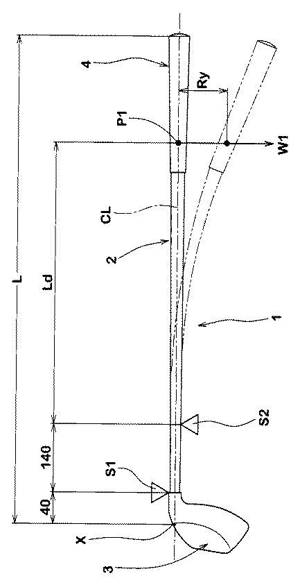
前記逆式フレックスRyとは、図4に示されるように、シャフト2の軸中心線CLが水平となるようにクラブ1のヘッド3側を支点S1及びS2で支えるとともに、グリップ4側の荷重点P1に1.25kgfの錘W1を吊り下げたときの前記荷重点P1における垂直方向のたわみ量である。ここで、支点S1はヘッド3の前記交点X(図1に示す)から40mmの位置、支点S2は支点S1から140mmの位置にそれぞれ設定される。また、支点S2から荷重点P1までの距離Ldは、クラブの番手に応じて次の通りとする。
ドライバー(#1):860mm
プラッシー(#2):847mm
スプーン (#3):835mm
バフィ (#4):822mm
クリーク (#5):809mm
(#7):796mm
As shown in FIG. 4, the inverse flex Ry means that the
Driver (# 1): 860mm
Plush (# 2): 847mm
Spoon (# 3): 835mm
Buffy (# 4): 822mm
Creek (# 5): 809mm
(# 7): 796mm
図5(a)乃至(c)には、平均ヘッドスピード43、45及び55m/sのそれぞれ10名のゴルファについて実打テストを行った結果を示す(クラブ全長45.25インチ、ロフト角10.0度、クラブ質量320g、ヘッド体積455cm3及びフェースの厚肉部厚さ3.4mm、薄肉部の厚さ2.0mm)。この結果から明らかなように、逆式フレックスRyが80mm未満であると、シャフト2が硬くなり過ぎるため、ヘッドスピードの早いゴルファの上記ヘッドスピードでも、シャフト2を十分にしならせることが困難になり、基本的な飛距離が十分に得られない他、フェース5の向きがアドレスした状態まで返り難く、打球の方向安定性が悪化する。逆に、逆式フレックスが110mmを超えると、上記ヘッドスピードのゴルファにとって、シャフト2が柔らかくなるため、かえってフェース5の向きが安定しなくなるなど打球の方向安定性が著しく低下する。このような観点より、前記逆式フレックスは、より好ましくは90mm以上が望ましく、またより好ましくは100mm以下が望ましい。このように、本発明では、逆式フレックスRyをヘッドスピードの速いゴルファに合わせて最適化することにより、基本的な打球の飛距離と方向性とを確保することができる。
5 (a) to 5 (c) show the results of an actual hit test for 10 golfers each with an average head speed of 43, 45 and 55 m / s (club overall length 45.25 inches,
このような逆式フレックスRyは、シャフト2の材料やその弾性率を変えることで上記範囲内に容易に調節することができる。
Such a reverse flex Ry can be easily adjusted within the above range by changing the material of the
次に、本発明では、上記逆式フレックスRyの値を前提として、種々実験を重ねたところ、該逆式フレックスRyと、フェース部6の薄肉部の分布とを関連付けることが、ミスショット時の飛距離の低下に非常に有効であることを知見した。即ち、上述のヘッドスピード(45〜55m/s)のゴルファが、逆式フレックスが80〜110mmのゴルフクラブ1を使用すると、そのトウダウン量がほぼ一定の範囲に収まる。このため、フェース部6において、このトウダウン量に応じた打点のバラツキ範囲を集中的に高反発化することで、ミスショット時でも飛距離(反発性能)の低下を最小限に抑え得ることができる。具体的には、フェース部6の反発性を高め得る薄肉部の分布を、以下詳述するように改善するものである。
Next, in the present invention, various experiments were repeated on the premise of the value of the inverse flex Ry, and as a result, the inverse flex Ry and the distribution of the thin portion of the face portion 6 can be correlated. It was found that it is very effective in reducing the flight distance. That is, if the golfer with the head speed (45 to 55 m / s) uses the
図6には、基準状態におかれた前記フェース部材3Aの正面図が、図7には図6の背面図が、図8には、図6のA−A部分端面図がそれぞれ示される。図から明らかなように、フェース5は、フェース溝やパンチマーク(いずれも図示省略)等を除いて実質的に平滑面で形成される。他方、フェース部6の背面6Bは、非平坦で形成される。これにより、フェース部6の厚さは、各部で異なっている。
6 shows a front view of the
本実施形態において、フェース部6は、その中央領域に設けられた中央厚肉部15と、該中央厚肉部15のトウ側かつクラウン側に設けられた小さい厚さのトウ・クラウン側薄肉部16と、前記中央厚肉部15のヒール側かつソール側に設けられた小さい厚さのヒール・ソール側薄肉部17とを含んで構成される。また、フェース部6は、前記厚肉部15及び薄肉部16、17の他に、前記中央厚肉部15のヒール側に設けられたヒール中肉部18と、前記中央厚肉部15のトウ側に設けられたトウ中肉部19と、前記中央厚肉部15のクラウン側に設けられたクラウン中肉部20と、前記中央厚肉部15のソール側に設けられたソール中肉部21とを含む。さらに、前記クラウン中肉部20と中央厚肉部15との間に形成されるヒール・クラウン薄肉部22と、前記ソール中肉部21と中央厚肉部15との間に形成されるトウ・ソール薄肉部23とが設けられる。
In this embodiment, the face portion 6 includes a central
前記中央厚肉部15は、フェース部6の中で最も大きい厚さを持っている。フェース部6の中央領域は、打球時に大きな衝撃力を受ける。したがって、該中央領域に厚さが最も大きい中央厚肉部15が設けられることにより、フェース部6の耐久性が向上する。ここで、フェース部6の中央領域とは、フェース部6の中空部i側を向くフェース背面周縁部5eの輪郭形状の面積重心SGを含む一定の面積を持つ領域である。なお、前記フェース背面周縁部5eは、図7及び8に示されるように、フェース部6の背面6Bと、クラウン部7、ソール部8及びサイド部9の各内側面との間の境界線とする。ただし、前記背面6Bと前記各部7ないし9の内側面とが応力集中を防止するための面取り状の円弧を介して接続される場合、フェース背面周縁部5eは、ヘッド断面における当該円弧Rの長さの中間点として便宜的に定められる。
The central
また、本実施形態の中央厚肉部15は、フェース背面周縁部5eの輪郭形状に沿って略横長の長円状をなす基部15aと、該基部15aの上部かつヒール側からクラウン側縁3A1までヒール側に傾斜してのびる上向きリブ15bと、前記基部15aの下部かつトウ側からソール側縁3A2までトウ側に傾斜してのびる下向きリブ15cとから構成される。このような中央厚肉部15は、前記基部15aによって、フェース5において最も撓み易い中央部の耐久性を確保できるという利点を有するとともに、両リブ15b及び15cが、フェース部6全体の耐久性を向上させている。上向きリブ15bは、中央厚肉部15側からクラウン側のフェース背面周縁部5eにのびるヒール側の上ヒール輪郭縁30aと、中央厚肉部15側からクラウン側のフェース背面周縁部5eにのびるトウ側の上トウ輪郭縁30bとを含んでいる。下向きリブ15cは、中央厚肉部15側からソール側のフェース背面周縁部5eにのびるヒール側の下ヒール輪郭縁30cと、中央厚肉部15側からソール側のフェース背面周縁部5eにのびるトウ側の下トウ輪郭縁30dとを含んでいる。
Further, the central
フェース部6の耐久性をより確実に向上させるために、中央厚肉部15の厚さtcは、好ましくは3.4mm以上、より好ましくは3.5mm以上が望ましい。他方、中央厚肉部15の厚さtcが過度に大きくなると、反発性の悪化やフェース重量の増大によりスイングバランスが悪化して打点のバラツキが大きくなるおそれがある。このような観点より、中央厚肉部15の厚さtcは、好ましくは4.0mm以下、より好ましくは3.9mm以下が望ましい。なお、前記中央厚肉部15は、実質的に一定の厚さで形成されるのが望ましい。
In order to improve the durability of the face part 6 more reliably, the thickness tc of the central
また、本実施形態の上向きリブ15b及び下向きリブ15cの厚さは、基部15aの厚さと実質的に一定の厚さで形成されているが、ヘッド3の質量を小さくする観点から、例えば上向きリブ15bは、クラウン側に向かって厚さが小さくなるとともに、下向きリブ15cは、ソール側に向かって厚さが小さくなる態様でも構わない。
Further, the thickness of the
また、フェース部6の耐久性の確保と反発性の悪化やフェース重量の増大を抑制する観点より、中央厚肉部15の面積MTは、フェース部6の背面6Bの全面積MGの好ましくは10%以上、より好ましくは15%以上が望ましく、また好ましくは35%以下、より好ましくは30%以下が望ましい。なお、フェース部6の背面6Bや中央厚肉部15の面積(これ以外にも後記する各部16乃至23の面積も同様)は、便宜上、該当する領域ないし部分を図2に示した垂直面VP(又はこれと平行な垂直面)に投影した二次元形状から求められる面積とする。
Further, from the viewpoint of ensuring the durability of the face portion 6 and suppressing the deterioration of resilience and the increase in the weight of the face, the area MT of the central
なお、前記背面6Bの全面積MGは、ヘッド3の体積に基づいて決定されるが、好ましくは33cm2以上、より好ましくは35cm2以上が望ましく、また好ましくは53cm2以下、より好ましくは47cm2以下が望ましい。
The total area MG of the
前記トウ・クラウン側薄肉部16及びヒール・ソール側薄肉部17は、本実施形態では一定の厚さで形成され、かつフェース部6の中で最も小さい厚さを有する。これにより、フェース5のトウ側及びヒール側でボールを打撃するミスショット時においても、フェース部6を十分に撓ませ、ひいては反発性の低下を最小限に抑制できる。従って、ミスショット時でも飛距離の低下を小さくできる。
In the present embodiment, the toe / crown side
発明者らの種々の実験の結果、ヘッドスピードが上述のように45〜55m/sのゴルファが、逆式フレックスRyが80〜110mmに設定されたゴルフクラブ1を使用すると、そのトウダウン量は、ほぼ一定の範囲に収まることが判明している。図9には、このようなゴルファの打撃位置が示される。図9から明らかなように、ヘッドスピードの速いゴルファの打撃位置は、前記背面6Bの面積重心SGからトウ側、ヒール側に特定の角度範囲に集中する傾向がある。従って、本発明のゴルフクラブ1では、打点のバラツキによるヘッド3の反発性の低下を最小限に抑制するために、厚さの小さいトウ・クラウン側薄肉部16及びヒール・ソール側薄肉部17をこの分布に合わせて配置することとした。
As a result of various experiments by the inventors, when a golfer having a head speed of 45 to 55 m / s as described above and using the
具体的に述べると、図6に示される前記正規状態における正面視において、トウ・クラウン側薄肉部16の面積重心SAとフェース部6の背面6Bの面積重心SGとを通る第1の直線K1は、前記水平面HPに対する角度θAが38〜45度に設定される必要がある。また、ヒール・ソール側薄肉部17の面積重心SBと前記面積重心SGとを通る第2の直線K2は、前記水平面HPに対する角度θBが40〜45度に設定される必要がある。さらに、トウ・クラウン薄肉部16は、中央厚肉部15側からクラウン側のフェース背面周縁部5eにのびるヒール側の輪郭縁16aと、中央厚肉部15側からクラウン側のフェース背面周縁部5eにのびるトウ側の輪郭縁16bとを含んでいる。これにより、トウ・クラウン側薄肉部16及びヒール・ソール側薄肉部17を、前記逆式フレックスによるゴルフクラブ1のトウダウン量に応じた打撃のバラツキ範囲に対して最適な位置に配することができる。なお、上記正面視とは、図2に符号Fで示されるように、フェース5を前記垂直面VPと直交する方向から見たヘッド3の形状として特定される。なお、前記各面積重心SA、SB及びSGは、後述する各面積MA、MB及びMGを基準として求められる。
Specifically, in the front view in the normal state shown in FIG. 6, the first straight line K1 passing through the area center of gravity SA of the toe / crown side
ここで、前記角度θAが、38度未満の場合又は45度を超える場合、或いは前記角度θBが、40度未満の場合又は45度を超える場合、トウダウン量に応じた打点の位置と前記薄肉部16及び17の位置とが合致せず、ミスショット時の反発性能が低下する。このような観点より、前記角度θAは、好ましくは40度以上が望ましく、また好ましくは43度以下が望ましい。同様に前記角度θBは、好ましくは42度以上が望ましく、また好ましくは44度以下が望ましい。
Here, when the angle θA is less than 38 degrees or exceeds 45 degrees, or when the angle θB is less than 40 degrees or exceeds 45 degrees, the position of the striking point according to the toe down amount and the thin portion The
また、トウ・クラウン側薄肉部16の厚さta及びヒール・ソール側薄肉部17の厚さtbは、過度に小さくなると、フェース5の耐久性が悪化するおそれがあり、逆に、過度に大きくなると、反発性が低下するおそれがある。従って、前記各薄肉部16及び17の厚さta及びtbは、好ましくは1.7mm以上、より好ましくは1.8mm以上が望ましく、また好ましくは2.4mm以下、より好ましくは2.2mm以下が望ましい。なお、フェース5にフェースライン等のインパクトエリアマーキングが設けられている場合、フェース部6の各部の厚さは、これらのインパクトエリアマーキングを埋めた状態で測定されるものとする。
Further, if the thickness ta of the toe / crown side
また、トウ・クラウン側薄肉部16の面積MA及びヒール・ソール側薄肉部17の面積MBが小さくなると、ヘッドの反発性を十分に向上できないおそれがある。逆に、前記面積MA及びMBが大きくなると、ヘッド3の耐久性が悪化するおそれがある。このような観点より、トウ・クラウン側薄肉部16の面積MAは、前記背面6Bの全面積MGの好ましくは5%以上、より好ましくは6%以上が望ましく、また好ましくは9%以下、より好ましくは8%以下が望ましい。また、ヒール・ソール側薄肉部17の面積MBは、前記全面積MGの好ましくは3%以上、より好ましくは4%以上が望ましく、また、好ましくは8%以下、より好ましくは7%以下が望ましい。とりわけ、トウ・クラウン側薄肉部16の面積MAが、ヒール・ソール側薄肉部17の面積MBよりも大きいのが望ましい。
Further, if the area MA of the toe / crown side
本実施形態において、前記トウ・クラウン側薄肉部16の形成領域は、前記面積重心SGを通る二直線の挟む角度αAで表され、この角度αAは、好ましくは30度以上、より好ましくは35度以上が望ましく、また好ましくは55度以下、より好ましくは50度以下に配設されるのが望ましい。同様に、ヒール・ソール側薄肉部17の形成領域は、前記面積重心SGを通るニ直線の挟む角度αBで表され、該角度αBは、好ましくは30度以上、より好ましくは35度以上が望ましく、また好ましくは50度以下、より好ましくは45度以下に配設されるのが望ましい。これにより、反発性とフェース5の耐久性とがバランス良く向上することができる。
In the present embodiment, the formation region of the toe / crown side
また、フェース部6には、薄肉部16及び17と同じ厚さを有するヒール・クラウン薄肉部22と、トウ・ソール薄肉部23とが設けられるのが望ましい。このようなヒール・クラウン薄肉部22の面積重心SCとフェース部6の背面6Bの面積重心SGとを通る第3の直線K3は、前記水平面HPに対する角度θCが35〜50度に設定されるのが望ましい。また、トウ・ソール薄肉部23の面積重心SBと前記面積重心SGとを通る第4の直線K4は、前記水平面HPに対する角度θDが40〜50度に設定されるのが望ましい。これにより、本実施形態のヘッド3は、ゴルファの打撃位置とは大きく離れたエリアの質量を削減されるため、ヘッドスピードの向上と耐久性とをバランス良く向上することができる。このような観点より、前記角度θCは、より好ましくは40度以上が望ましく、またより好ましくは45度%以下が望ましい。同様に前記角度θDは、より好ましくは42度以上が望ましく、またより好ましくは47度以下が望ましい。
The face 6 is preferably provided with a heel / crown
また、特に限定されるものではないが、ヒール・クラウン薄肉部22の面積MC及びトウ・ソール薄肉部23の面積MDは、小さくなると前記作用効果が発揮され難く、逆に大きくなるとフェース部6の耐久性が悪化し易い。このような観点より、ヒール・クラウン薄肉部22の面積MCは、前記背面6Bの全面積MGの好ましくは2%以上、より好ましくは4%以上が望ましく、また好ましくは10%以下、より好ましくは8%以下が望ましい。また、トウ・ソール薄肉部23の面積MDは、前記全面積MGの好ましくは2%以上、より好ましくは3%以上が望ましく、また、好ましくは10%以下、より好ましくは7%以下が望ましい。
Although not particularly limited, the area MC of the heel / crown
前記中肉部18乃至21は、薄肉部16、17、22及び23と中央厚肉部15との間に大きな剛性段差が形成されるのを抑制し、そこへの応力集中を効果的に防止しうる。これにより、フェース部6の耐久性がより向上する。
The
また、各中肉部18乃至21の合計面積MSは、フェース部6の耐久性とヘッド3の質量増加の抑制とをバランス良く確保させるため、好ましくはフェース部6の背面6Bの全面積MGに対して20%以上、より好ましくは30%以上が望ましく、また、好ましくは60%以下、より好ましくは50%以下が望ましい。
Further, the total area MS of each of the
同様の観点より、前記各中肉部18乃至21の厚さは、前記中央厚肉部15の厚さtcの好ましくは45%以上、より好ましくは50%以上が望ましく、また好ましくは85%以下、より好ましくは80%以下が望ましい。
From the same viewpoint, the thickness of each of the
また、前記中央厚肉部15のクラウン側には、フェース背面周縁部5eに向かって厚さが滑らかに減少しかつ半環状にのびるクラウン側中央厚さ移行部24aが設けられる。また、中央厚肉部15のソール側には、フェース背面周縁部5eに向かって厚さが滑らかに減少しかつ半環状にのびるソール側中央厚さ移行部24bが設けられる。
Further, on the crown side of the central
また、上向きリブ15bとヒール・クラウン薄肉部22との間、上向きリブ15bとヒール中肉部18との間、下向きリブ15cとトウ中肉部19との間及び下向きリブ15cとトウ・ソール薄肉部23との間には、上向きリブ15b又は下向きリブ15cから厚さが滑らかに減少して変化する外側厚さ移行部25aが設けられる。また、クラウン中肉部20とヒール・クラウン薄肉部22との間、クラウン中肉部20とトウ・クラウン側薄肉部16との間、トウ中肉部19とトウ・クラウン側薄肉部16との間には、前記外側厚さ移行部25aよりも幅の小さい小外側厚さ移行部25bが設けられる。同様に、ソール中肉部21とヒール・ソール側薄肉部17との間、ソール中肉部21とトウ・ソール薄肉部23との間及びヒール・ソール側薄肉部17とヒール中肉部18との間にも小外側厚さ移行部25bが設けられる。これらの各厚さ移行部24及び25は、各部の厚さの差に伴う大きな剛性段差が生じるのを防止し、応力集中などを防いでフェース部6の耐久性を高めるのに役立つ。なお、本実施形態の各厚さ移行部24、25は、一定の幅で形成されている。
Further, between the
以上、本発明について詳細に説明したが、本発明は上記の具体的な実施形態に限定させることなく、必要に応じて種々の態様に変更しうる。 Although the present invention has been described in detail above, the present invention is not limited to the specific embodiments described above, and can be changed to various modes as necessary.
本発明の効果を確認するために、図6及び表1の仕様に基づいたウッド型ゴルフクラブヘッド(ドライバー)にSRIスポーツ社製のカーボンシャフト(Miyazaki Kusala Blue、フレックスS)を装着して、45〜47インチのクラブ全長のウッド型クラブが試作され、反発性能についてテストが行なわれた。各ヘッドは、Ti−6Al−4Vのロストワックス精密鋳造品からなるヘッド本体と、Ti−6Al−4Vのプレス成形品からなる板状のフェース部材とをレーザー溶接することにより形成された2ピース構造である。表1に示すパラメータ以外はすべて同一であり、主な共通仕様は次の通りである。また、前記角度θA及びθBは、クラブ質量を一定としつつ変化させた。 In order to confirm the effect of the present invention, a carbon shaft (Miyazaki Kusala Blue, Flex S) manufactured by SRI Sports was attached to a wood type golf club head (driver) based on the specifications shown in FIG. A 47-inch long wood-type club was prototyped and tested for resilience performance. Each head is a two-piece structure formed by laser welding a head main body made of a Ti-6Al-4V lost wax precision cast product and a plate-like face member made of a Ti-6Al-4V press-formed product. It is. The parameters other than those shown in Table 1 are all the same, and the main common specifications are as follows. The angles θA and θB were changed while keeping the club mass constant.
ライ角α:57.5度
ロフト角β:10.0度
ヘッド体積V:455cm3
ヘッド質量:197g
フェース背面の全面積MG:43cm2
中央厚肉部の厚さtc:3.7mm
中央厚肉部とフェース部の背面との面積比MT/MG:10〜35%
トウ・クラウン側薄肉部の厚さta:2.0mm
トウ・クラウン側薄肉部とフェース部の背面との面積比MA/MG:5〜9%
ヒール・ソール側薄肉部の厚さtb:2.0mm
ヒール・ソール側薄肉部とフェース部の背面との面積比MB/MG:3〜8%
ヒール・クラウン薄肉部の厚さ:2.0mm
ヒール・クラウン薄肉部とフェース部の背面との面積比MC/MG:2〜10%
トウ・ソール薄肉部の厚さ:2.0mm
トウ・ソール薄肉部とフェース部の背面との面積比MD/MG:2〜10%
各中肉部厚さ/中央厚肉部の厚さ:50〜80%
中肉部の合計面積とフェース部の背面との面積比MS/MG:20〜60%
各厚さ移行部は、滑らかに厚さが変化している。
テスト方法は、次の通りである。
Lie angle α: 57.5 degrees Loft angle β: 10.0 degrees Head volume V: 455 cm 3
Head mass: 197 g
Total area MG on the back of the face: 43cm 2
Thickness of central thick part tc: 3.7 mm
Area ratio MT / MG between the central thick part and the back of the face part: 10 to 35%
Thickness of thin part on the toe and crown side: 2.0mm
Area ratio MA / MG: 5-9% between thin toe / crown side and back of face
Thickness of thin heel / sole side tb: 2.0mm
Area ratio MB / MG of thin heel / sole side and back of face part: 3-8%
Thin heel / crown thickness: 2.0mm
Area ratio of thin heel / crown to the back of the face MC / MG: 2 to 10%
Toe sole thickness: 2.0mm
Area ratio MD / MG: 2 to 10% between the toe sole thin part and the back of the face part
Thickness of each middle thickness / thickness at the center: 50-80%
Area ratio MS / MG: 20 to 60% of the total area of the middle part and the back of the face part
Each thickness transition portion smoothly changes in thickness.
The test method is as follows.
<反発性能>
上記の各供試クラブで、10名のテスター(アベレージゴルファ)(ヘッドスピード45〜55m/s)が、好みの長さのゴルフクラブを用いて各10球ずつ実打テストを行い、打撃直前のヘッドスピードHSとボールの打ちだし初速BSとを計測し、その速度比BS/HSの平均を算出した。なお、ゴルフボールには、市販の3ピースゴルフボール(SRIスポーツ(株)製の「XXIO」(同社の登録商標))が用いられた。結果は、数値が大きいほど良好である。テストの結果などを表1に示す。なお、表1中の「トウ部重心角度θA」とは、トウ・クラウン側薄肉部16の面積重心SAとフェース部6の背面6Bの面積重心SGとを通る第1の直線K1の水平面HPに対する角度をいい、「ヒール部重心角度θB」とは、ヒール・ソール側薄肉部17の面積重心SBとフェース部6の背面6Bの面積重心SGとを通る第2の直線K2の水平面HPに対する角度をいう。また、テスターの平均ヘッドスピード及び使用したクラブ全長は表2の通りである。
<Rebound performance>
In each of the above test clubs, 10 testers (average golfers) (head speed of 45 to 55 m / s) performed actual hit tests for 10 balls each using a golf club of the desired length, and immediately before hitting. The head speed HS and the initial ball speed BS were measured, and the average of the speed ratio BS / HS was calculated. As the golf ball, a commercially available three-piece golf ball (“XXIO” (registered trademark of the company) manufactured by SRI Sports Co., Ltd.) was used. The result is better as the value is larger. Table 1 shows the test results. The “toe center of gravity angle θA” in Table 1 is relative to the horizontal plane HP of the first straight line K1 passing through the area center of gravity SA of the toe / crown side
テストの結果、実施例のゴルフクラブは、比較例に比べて反発性能が有意に向上していることが確認できる。なお、トウ・クラウン側薄肉部とヒール・ソール側薄肉部との面積比MA/MBを200〜60%の範囲で変化させて反発性能を確認したが、表1と同様の傾向を示していた。 As a result of the test, it can be confirmed that the rebound performance of the golf club of the example is significantly improved as compared with the comparative example. The resilience performance was confirmed by changing the area ratio MA / MB between the thin portion on the toe / crown side and the thin portion on the heel / sole side in the range of 200 to 60%, but showed the same tendency as in Table 1. .
1 ゴルフクラブ
2 シャフト
3 ゴルフクラブヘッド
5 フェース
6 フェース部
6B 背面
15 中央厚肉部
16 トウ・クラウン側薄肉部
17 ヒール・ソール側薄肉部
HP 水平面
K1 第1の直線
K2 第2の直線
SA トウ・クラウン側薄肉部の面積重心
SB ヒール・ソール側薄肉部の面積重心
SG フェース部の背面の面積重心
Ry 逆式フレックス
DESCRIPTION OF
Claims (7)
逆式フレックスが、80〜110mmであるとともに、
前記フェース部は、中央領域に設けられた中央厚肉部と、該中央厚肉部のトウ側かつクラウン側に設けられた小さい厚さのトウ・クラウン側薄肉部と、前記中央厚肉部のヒール側かつソール側に設けられた小さい厚さのヒール・ソール側薄肉部とを含み、
規定のライ角及びロフト角で水平面に載置された基準状態の正面視において、
前記トウ・クラウン側薄肉部の面積重心と前記フェース部の背面の面積重心とを通る第1の直線は、前記水平面に対する角度θAが38〜45度であり、かつ、
前記ヒール・ソール側薄肉部の面積重心と前記フェース部の背面の面積重心とを通る第2の直線は、前記水平面に対する角度θBが40〜45度であり、
前記トウ・クラウン側薄肉部は、前記中央厚肉部側からクラウン側のフェース背面周縁部にのびるヒール側の輪郭縁と、前記中央厚肉部側からクラウン側のフェース背面周縁部にのびるトウ側の輪郭縁とを含むことを特徴とするゴルフクラブ。 A golf club comprising a shaft and a golf club head having a hollow structure including a face portion fixed to one end of the shaft and having a face for hitting a ball,
The reverse flex is 80-110mm,
The face portion includes a central thick portion provided in a central region, a small thickness toe / crown side thin portion provided on the toe side and the crown side of the central thick portion, and the central thick portion. Including a thin heel / sole side thin portion of a small thickness provided on the heel side and the sole side,
In the front view of the reference state placed on the horizontal surface at the specified lie angle and loft angle,
The first straight line passing through the area centroid of the thin portion on the toe / crown side and the area centroid of the back surface of the face portion has an angle θA with respect to the horizontal plane of 38 to 45 degrees, and
Second straight line passing through the back of the centroid of the centroid and the face portion of the heel-sole-side thin portion, Ri angle θB is 40 to 45 degrees der to said horizontal plane,
The thin portion on the toe / crown side includes a heel side contour edge extending from the central thick portion side to the crown rear face peripheral portion, and a toe side extending from the central thick portion side to the crown rear face peripheral portion. And a contour edge of the golf club.
前記ヒール・クラウン薄肉部は、前記ヒール・ソール側薄肉部と同じ厚さであり、The heel / crown thin portion has the same thickness as the heel / sole side thin portion,
前記トウ・ソール薄肉部は、前記トウ・クラウン側薄肉部と同じ厚さである請求項1記載のゴルフクラブ。The golf club according to claim 1, wherein the toe-sole thin portion has the same thickness as the toe-crown side thin portion.
前記上向きリブは、前記中央厚肉部側からクラウン側の前記フェース背面周縁部にのびるヒール側の上ヒール輪郭縁と、前記中央厚肉部側からクラウン側の前記フェース背面周縁部にのびるトウ側の上トウ輪郭縁とを含み、 The upward rib includes an upper heel contour edge extending from the central thick part side to the face back peripheral part on the crown side, and a toe side extending from the central thick part side to the face rear peripheral part on the crown side. Including an upper toe contour edge,
前記下向きリブは、前記中央厚肉部側からソール側の前記フェース背面周縁部にのびるヒール側の下ヒール輪郭縁と、前記中央厚肉部側からソール側の前記フェース背面周縁部にのびるトウ側の下トウ輪郭縁とを含み、 The downward rib includes a heel side lower heel contour edge extending from the central thick part side to the face rear peripheral part on the sole side, and a toe side extending from the central thick part side to the face rear peripheral part on the sole side. Including lower toe contour edges,
前記フェース部の背面の面積重心は、前記上ヒール輪郭縁をソール側へ滑らかに延長させた上ヒール仮想線と、前記上トウ輪郭縁をソール側へ滑らかに延長させた上トウ仮想線との間に設けられ、かつ、前記下ヒール輪郭縁をクラウン側へ滑らかに延長させた下ヒール仮想線と、前記下トウ輪郭縁をクラウン側へ滑らかに延長させた下トウ仮想線との間に設けられる請求項1又は2に記載のゴルフクラブ。 The center of gravity of the back surface of the face portion is an upper heel imaginary line in which the upper heel contour edge is smoothly extended to the sole side and an upper toe imaginary line in which the upper toe contour edge is smoothly extended to the sole side. A lower heel imaginary line that is provided between the lower heel contour edge and smoothly extends to the crown side, and a lower toe imaginary line that smoothly extends the lower toe contour edge to the crown side. The golf club according to claim 1 or 2 to be used.
前記トウ・クラウン側薄肉部の面積は、前記フェース部の背面の全面積の5〜9%、 The area of the thin part on the toe / crown side is 5-9% of the total area of the back surface of the face part,
前記ヒール・ソール側薄肉部の面積は、前記フェース部の背面の全面積の3〜8%である請求項1乃至3のいずれかに記載のゴルフクラブ。 4. The golf club according to claim 1, wherein an area of the thin portion on the heel / sole side is 3 to 8% of a total area of a back surface of the face portion. 5.
逆式フレックスが、80〜110mmであるとともに、
前記フェース部は、中央領域に設けられた中央厚肉部と、該中央厚肉部のトウ側かつクラウン側に設けられた小さい厚さのトウ・クラウン側薄肉部と、前記中央厚肉部のヒール側かつソール側に設けられた小さい厚さのヒール・ソール側薄肉部とを含み、
規定のライ角及びロフト角で水平面に載置された基準状態の正面視において、
前記トウ・クラウン側薄肉部の面積重心と前記フェース部の背面の面積重心とを通る第1の直線は、前記水平面に対する角度θAが38〜45度であり、かつ、
前記ヒール・ソール側薄肉部の面積重心と前記フェース部の背面の面積重心とを通る第2の直線は、前記水平面に対する角度θBが40〜45度であり、
前記中央厚肉部の面積は、前記フェース部の背面の全面積の10%〜35%、
前記トウ・クラウン側薄肉部の面積は、前記フェース部の背面の全面積の5〜9%、
前記ヒール・ソール側薄肉部の面積は、前記フェース部の背面の全面積の3〜8%であり、
前記トウ・クラウン側薄肉部は、前記フェース部の背面の前記面積重心と前記トウ・クラウン側薄肉部のソール側の外端とを通る直線、及び、前記フェース部の背面の前記面積重心と前記トウ・クラウン側薄肉部のヒール側の外端とを通る直線が挟む角度αAが、30〜55度、
前記ヒール・ソール側薄肉部は、前記フェース部の背面の前記面積重心と前記ヒール・ソール側薄肉部のクラウン側の外端とを通る直線、及び、前記フェース部の背面の前記面積重心と前記ヒール・ソール側薄肉部のトウ側の外端とを通る直線が挟む角度αBが、30〜50度である
ことを特徴とするゴルフクラブ。 A golf club comprising a shaft and a golf club head having a hollow structure including a face portion fixed to one end of the shaft and having a face for hitting a ball,
The reverse flex is 80-110mm,
The face portion includes a central thick portion provided in a central region, a small thickness toe / crown side thin portion provided on the toe side and the crown side of the central thick portion, and the central thick portion. Including a thin heel / sole side thin portion of a small thickness provided on the heel side and the sole side,
In the front view of the reference state placed on the horizontal surface at the specified lie angle and loft angle,
The first straight line passing through the area centroid of the thin portion on the toe / crown side and the area centroid of the back surface of the face portion has an angle θA with respect to the horizontal plane of 38 to 45 degrees, and
The second straight line passing through the area center of gravity of the heel / sole side thin part and the area center of gravity of the back surface of the face part has an angle θB of 40 to 45 degrees with respect to the horizontal plane,
The area of the central thick part is 10% to 35% of the total area of the back surface of the face part,
The area of the thin part on the toe / crown side is 5-9% of the total area of the back surface of the face part,
The area of the thin part on the heel / sole side is 3 to 8% of the total area of the back surface of the face part,
The thin portion on the toe / crown side is a straight line that passes through the area center of gravity on the back surface of the face portion and the outer end on the sole side of the thin portion on the toe / crown side, and the center of gravity area on the back surface of the face portion and the The angle αA between which the straight line passing through the outer end on the heel side of the thin portion on the toe crown side is 30 to 55 degrees,
The thin portion on the heel / sole side is a straight line passing through the center of gravity of the back surface of the face portion and the outer end on the crown side of the thin portion of the heel / sole side, and the center of gravity of the area on the back surface of the face portion and the A golf club characterized in that an angle αB between which a straight line passing through an outer end on the toe side of the heel / sole side thin portion is 30 to 50 degrees.
Priority Applications (2)
| Application Number | Priority Date | Filing Date | Title |
|---|---|---|---|
| JP2010294488A JP5823122B2 (en) | 2010-12-29 | 2010-12-29 | Golf club |
| US13/338,772 US8814724B2 (en) | 2010-12-29 | 2011-12-28 | Golf club |
Applications Claiming Priority (1)
| Application Number | Priority Date | Filing Date | Title |
|---|---|---|---|
| JP2010294488A JP5823122B2 (en) | 2010-12-29 | 2010-12-29 | Golf club |
Publications (2)
| Publication Number | Publication Date |
|---|---|
| JP2012139410A JP2012139410A (en) | 2012-07-26 |
| JP5823122B2 true JP5823122B2 (en) | 2015-11-25 |
Family
ID=46381243
Family Applications (1)
| Application Number | Title | Priority Date | Filing Date |
|---|---|---|---|
| JP2010294488A Active JP5823122B2 (en) | 2010-12-29 | 2010-12-29 | Golf club |
Country Status (2)
| Country | Link |
|---|---|
| US (1) | US8814724B2 (en) |
| JP (1) | JP5823122B2 (en) |
Cited By (4)
| Publication number | Priority date | Publication date | Assignee | Title |
|---|---|---|---|---|
| US10888747B2 (en) | 2008-07-15 | 2021-01-12 | Taylor Made Golf Company, Inc. | Aerodynamic golf club head |
| US11045694B2 (en) | 2008-07-15 | 2021-06-29 | Taylor Made Golf Company, Inc. | Aerodynamic golf club head |
| US11130026B2 (en) | 2008-07-15 | 2021-09-28 | Taylor Made Golf Company, Inc. | Aerodynamic golf club head |
| US12128278B2 (en) | 2008-07-15 | 2024-10-29 | Taylor Made Golf Company, Inc. | Aerodynamic golf club head |
Families Citing this family (36)
| Publication number | Priority date | Publication date | Assignee | Title |
|---|---|---|---|---|
| JP5185992B2 (en) * | 2010-11-02 | 2013-04-17 | ダンロップスポーツ株式会社 | Golf club |
| JP2015517880A (en) * | 2012-05-31 | 2015-06-25 | ナイキ イノベイト セー. フェー. | Golf club having a ball striking plate with thin spoke-like reinforcing ribs |
| US8979672B2 (en) | 2013-01-25 | 2015-03-17 | Dunlop Sports Co. Ltd. | Golf club head |
| JP6472161B2 (en) * | 2013-07-31 | 2019-02-20 | 住友ゴム工業株式会社 | Golf club head |
| JP5583827B1 (en) * | 2013-07-31 | 2014-09-03 | ダンロップスポーツ株式会社 | Golf club head |
| JP6219108B2 (en) * | 2013-09-25 | 2017-10-25 | ダンロップスポーツ株式会社 | Golf club set |
| US20150375068A1 (en) * | 2014-06-30 | 2015-12-31 | Dunlop Sports Co. Ltd. | Golf club head |
| US12121782B2 (en) * | 2014-08-26 | 2024-10-22 | Parsons Xtreme Golf, LLC | Golf club heads and methods to manufacture golf club heads |
| US11000742B2 (en) | 2014-08-26 | 2021-05-11 | Parsons Xtreme Golf, LLC | Golf club heads and methods to manufacture golf club heads |
| US12179072B2 (en) * | 2014-08-26 | 2024-12-31 | Parsons Extreme Golf, Llc | Golf club heads and methods to manufacture golf club heads |
| US11697050B2 (en) * | 2014-08-26 | 2023-07-11 | Parsons Xtreme Golf, LLC | Golf club heads and methods to manufacture golf club heads |
| US9669270B2 (en) * | 2014-08-26 | 2017-06-06 | Parsons Xtreme Golf, LLC | Golf club heads and methods to manufacture golf club heads |
| US10532257B2 (en) | 2014-08-26 | 2020-01-14 | Parsons Xtreme Golf, LLC | Golf club heads and methods to manufacture golf club heads |
| US11130025B2 (en) | 2014-10-24 | 2021-09-28 | Karsten Manufacturing Corporation | Golf club heads with energy storage features |
| US11534663B2 (en) * | 2015-01-23 | 2022-12-27 | Karsten Manufacturing Corporation | Golf club head having face reinforcing structure |
| KR102618408B1 (en) | 2015-01-23 | 2023-12-26 | 카스턴 매뉴팩츄어링 코오포레이숀 | Golf club heads with chamfers and related methods |
| JP5848839B1 (en) * | 2015-06-03 | 2016-01-27 | ダンロップスポーツ株式会社 | Golf club head |
| US11618306B2 (en) | 2016-10-27 | 2023-04-04 | Nicholas J. Singer | Skeleton for truck bed and convertible top |
| US11617925B2 (en) | 2019-03-11 | 2023-04-04 | Parsons Xtreme Golf, LLC | Golf club heads and methods to manufacture golf club heads |
| US11484756B2 (en) | 2017-01-10 | 2022-11-01 | Parsons Xtreme Golf, LLC | Golf club heads and methods to manufacture golf club heads |
| US11654338B2 (en) | 2017-01-10 | 2023-05-23 | Parsons Xtreme Golf, LLC | Golf club heads and methods to manufacture golf club heads |
| US12290725B2 (en) | 2017-01-10 | 2025-05-06 | Parsons Xtreme Golf, LLC | Golf club heads and methods to manufacture golf club heads |
| US11745067B2 (en) | 2017-03-29 | 2023-09-05 | Parsons Xtreme Golf, LLC | Golf club heads and methods to manufacture golf club heads |
| KR102794320B1 (en) * | 2017-12-22 | 2025-04-09 | 카스턴 매뉴팩츄어링 코오포레이숀 | Golf club head with variable face thickness |
| US11707655B2 (en) | 2018-02-12 | 2023-07-25 | Parsons Xtreme Golf, LLC | Golf club heads and methods to manufacture golf club heads |
| US12109464B2 (en) | 2018-02-12 | 2024-10-08 | Parsons Xtreme Golf, LLC | Golf club heads and methods to manufacture golf club heads |
| US12324967B2 (en) | 2018-02-12 | 2025-06-10 | Parsons Xtreme Golf, LLC | Golf club heads and methods to manufacture golf club heads |
| US11839800B2 (en) | 2018-02-12 | 2023-12-12 | Parsons Xtreme Golf, LLC | Golf club heads and methods to manufacture golf club heads |
| US11938385B1 (en) | 2018-02-12 | 2024-03-26 | Parsons Xtreme Golf, LLC | Golf club heads and methods to manufacture golf club heads |
| US11839799B2 (en) | 2019-01-02 | 2023-12-12 | Parsons Xtreme Golf, LLC | Golf club heads and methods to manufacture golf club heads |
| US12434112B2 (en) | 2019-03-11 | 2025-10-07 | Parsons Xtreme Golf, LLC | Golf club heads and methods to manufacture golf club heads |
| US11806589B2 (en) | 2019-03-11 | 2023-11-07 | Parsons Xtreme Golf, LLC | Golf club heads and methods to manufacture golf club heads |
| US11839798B2 (en) | 2019-03-11 | 2023-12-12 | Parsons Xtreme Golf, LLC | Golf club heads and methods to manufacture golf club heads |
| US11207573B2 (en) * | 2019-07-24 | 2021-12-28 | Acushnet Company | Striking face of a golf club |
| US12194351B1 (en) | 2021-11-08 | 2025-01-14 | Parsons Xtreme Golf, LLC | Golf club heads and methods to manufacture golf club heads |
| US12377325B2 (en) | 2021-11-08 | 2025-08-05 | Parsons Xtreme Golf, LLC | Golf club heads and methods to manufacture golf club heads |
Family Cites Families (33)
| Publication number | Priority date | Publication date | Assignee | Title |
|---|---|---|---|---|
| US2087685A (en) * | 1935-02-16 | 1937-07-20 | William A Blair | Golf club |
| JPH09262328A (en) * | 1996-03-28 | 1997-10-07 | Bridgestone Sports Co Ltd | Golf club |
| WO2001083049A1 (en) | 2000-05-02 | 2001-11-08 | Mizuno Corporation | Golf club |
| US6840872B2 (en) * | 2002-01-29 | 2005-01-11 | Yonex Kabushiki Kaisha | Golf club head |
| JP2003290398A (en) * | 2002-01-29 | 2003-10-14 | Yonex Co Ltd | Golf club head |
| US20030220157A1 (en) * | 2002-05-23 | 2003-11-27 | Dennis Tool Company | Golf club head with highly polished hard contact fact |
| US20040132544A1 (en) * | 2003-01-08 | 2004-07-08 | Doi Douglas Alan | Golf club head |
| US6926618B2 (en) * | 2003-05-19 | 2005-08-09 | Karsten Manufacturing Corporation | Golf club with diagonally reinforced contoured front wall |
| US7192364B2 (en) * | 2003-05-27 | 2007-03-20 | Plus 2 International, Inc. | Golf club head with a stiffening plate |
| JP4632342B2 (en) * | 2003-11-11 | 2011-02-16 | Sriスポーツ株式会社 | Golf club head |
| JP4365676B2 (en) * | 2003-12-19 | 2009-11-18 | Sriスポーツ株式会社 | Wood type golf club head |
| US8012041B2 (en) * | 2004-10-07 | 2011-09-06 | Callaway Golf Company | Golf club head with variable face thickness |
| JP2006141806A (en) * | 2004-11-22 | 2006-06-08 | Sri Sports Ltd | Golf club head |
| JP4451797B2 (en) * | 2005-02-25 | 2010-04-14 | Sriスポーツ株式会社 | Golf club head |
| JP4528241B2 (en) * | 2005-04-08 | 2010-08-18 | Sriスポーツ株式会社 | Golf club |
| JP2007025761A (en) * | 2005-07-12 | 2007-02-01 | Sri Sports Ltd | Design method of golf club head and golf club head |
| US7549934B2 (en) * | 2005-09-07 | 2009-06-23 | Acushnet Company | Metal wood club with improved hitting face |
| US8439769B2 (en) * | 2005-09-07 | 2013-05-14 | Acushnet Company | Metal wood club with improved hitting face |
| US20080004129A1 (en) * | 2006-06-28 | 2008-01-03 | O-Ta Precision Industry Co., Inc. | Golf club head |
| US7427240B2 (en) * | 2006-06-28 | 2008-09-23 | Sri Sports Limited | Shaft for golf clubs and golf club |
| US7387579B2 (en) * | 2006-06-28 | 2008-06-17 | O-Ta Precision Industry Co., Inc. | Golf club head |
| JP4326559B2 (en) * | 2006-11-29 | 2009-09-09 | Sriスポーツ株式会社 | Golf club head |
| JP4365871B2 (en) * | 2007-04-05 | 2009-11-18 | Sriスポーツ株式会社 | Golf club head |
| JP5247101B2 (en) * | 2007-09-26 | 2013-07-24 | ブリヂストンスポーツ株式会社 | Golf club head |
| JP4944830B2 (en) * | 2008-04-03 | 2012-06-06 | Sriスポーツ株式会社 | Golf club head |
| JP5086884B2 (en) * | 2008-05-13 | 2012-11-28 | ダンロップスポーツ株式会社 | Golf club head and manufacturing method thereof |
| JP5349006B2 (en) * | 2008-10-29 | 2013-11-20 | ブリヂストンスポーツ株式会社 | Golf club head |
| US8070623B2 (en) * | 2008-11-21 | 2011-12-06 | Nike, Inc. | Golf club head or other ball striking device having stiffened face portion |
| JP5451187B2 (en) * | 2009-06-02 | 2014-03-26 | ブリヂストンスポーツ株式会社 | Golf club head |
| JP5421147B2 (en) * | 2010-02-15 | 2014-02-19 | ブリヂストンスポーツ株式会社 | Golf club head |
| JP5185992B2 (en) * | 2010-11-02 | 2013-04-17 | ダンロップスポーツ株式会社 | Golf club |
| JP5174129B2 (en) * | 2010-11-22 | 2013-04-03 | ダンロップスポーツ株式会社 | Golf club head |
| JP5823121B2 (en) * | 2010-12-28 | 2015-11-25 | ダンロップスポーツ株式会社 | Golf club |
-
2010
- 2010-12-29 JP JP2010294488A patent/JP5823122B2/en active Active
-
2011
- 2011-12-28 US US13/338,772 patent/US8814724B2/en active Active
Cited By (9)
| Publication number | Priority date | Publication date | Assignee | Title |
|---|---|---|---|---|
| US10888747B2 (en) | 2008-07-15 | 2021-01-12 | Taylor Made Golf Company, Inc. | Aerodynamic golf club head |
| US11045694B2 (en) | 2008-07-15 | 2021-06-29 | Taylor Made Golf Company, Inc. | Aerodynamic golf club head |
| US11130026B2 (en) | 2008-07-15 | 2021-09-28 | Taylor Made Golf Company, Inc. | Aerodynamic golf club head |
| US11465019B2 (en) | 2008-07-15 | 2022-10-11 | Taylor Made Golf Company, Inc. | Aerodynamic golf club head |
| US11633651B2 (en) | 2008-07-15 | 2023-04-25 | Taylor Made Golf Company, Inc. | Aerodynamic golf club head |
| US11707652B2 (en) | 2008-07-15 | 2023-07-25 | Taylor Made Golf Company, Inc. | Aerodynamic golf club head |
| US12070663B2 (en) | 2008-07-15 | 2024-08-27 | Taylor Made Golf Company, Inc. | Aerodynamic golf club head |
| US12128278B2 (en) | 2008-07-15 | 2024-10-29 | Taylor Made Golf Company, Inc. | Aerodynamic golf club head |
| US12364908B2 (en) | 2008-07-15 | 2025-07-22 | Taylor Made Golf Company, Inc. | Aerodynamic golf club head |
Also Published As
| Publication number | Publication date |
|---|---|
| US8814724B2 (en) | 2014-08-26 |
| US20120172145A1 (en) | 2012-07-05 |
| JP2012139410A (en) | 2012-07-26 |
Similar Documents
| Publication | Publication Date | Title |
|---|---|---|
| JP5823122B2 (en) | Golf club | |
| JP5185992B2 (en) | Golf club | |
| JP5823121B2 (en) | Golf club | |
| JP5181052B2 (en) | Golf club set | |
| JP5174129B2 (en) | Golf club head | |
| JP4365871B2 (en) | Golf club head | |
| JP4944830B2 (en) | Golf club head | |
| JP4326559B2 (en) | Golf club head | |
| JP5989509B2 (en) | Golf club head and golf club | |
| JP6295459B2 (en) | Iron type golf club head | |
| JP2007136069A (en) | Golf club head | |
| JP2013027587A (en) | Golf club head | |
| JP2008200118A (en) | Golf club head | |
| JP2010029379A (en) | Wood-type golf club head | |
| JP7707665B2 (en) | Golf Club Head | |
| JP5548281B2 (en) | Iron type golf club head | |
| JP5525570B2 (en) | Iron type golf club head | |
| JP4723397B2 (en) | Golf club head for putter and golf putter | |
| JP5162039B2 (en) | Iron type golf club head | |
| JP5175688B2 (en) | Iron type golf club head | |
| JP2019110974A (en) | Golf club head | |
| JP6267540B2 (en) | Golf club head | |
| JP2021100461A (en) | Golf club head and golf club | |
| JP4657484B2 (en) | Golf club head and golf club |
Legal Events
| Date | Code | Title | Description |
|---|---|---|---|
| A621 | Written request for application examination |
Free format text: JAPANESE INTERMEDIATE CODE: A621 Effective date: 20131127 |
|
| A977 | Report on retrieval |
Free format text: JAPANESE INTERMEDIATE CODE: A971007 Effective date: 20140613 |
|
| A131 | Notification of reasons for refusal |
Free format text: JAPANESE INTERMEDIATE CODE: A131 Effective date: 20140617 |
|
| A521 | Request for written amendment filed |
Free format text: JAPANESE INTERMEDIATE CODE: A523 Effective date: 20140811 |
|
| A131 | Notification of reasons for refusal |
Free format text: JAPANESE INTERMEDIATE CODE: A131 Effective date: 20150428 |
|
| A521 | Request for written amendment filed |
Free format text: JAPANESE INTERMEDIATE CODE: A523 Effective date: 20150605 |
|
| TRDD | Decision of grant or rejection written | ||
| A01 | Written decision to grant a patent or to grant a registration (utility model) |
Free format text: JAPANESE INTERMEDIATE CODE: A01 Effective date: 20150915 |
|
| A61 | First payment of annual fees (during grant procedure) |
Free format text: JAPANESE INTERMEDIATE CODE: A61 Effective date: 20151007 |
|
| R150 | Certificate of patent or registration of utility model |
Ref document number: 5823122 Country of ref document: JP Free format text: JAPANESE INTERMEDIATE CODE: R150 |
|
| R250 | Receipt of annual fees |
Free format text: JAPANESE INTERMEDIATE CODE: R250 |
|
| R250 | Receipt of annual fees |
Free format text: JAPANESE INTERMEDIATE CODE: R250 |
|
| R250 | Receipt of annual fees |
Free format text: JAPANESE INTERMEDIATE CODE: R250 |
|
| R250 | Receipt of annual fees |
Free format text: JAPANESE INTERMEDIATE CODE: R250 |
|
| R250 | Receipt of annual fees |
Free format text: JAPANESE INTERMEDIATE CODE: R250 |
|
| R250 | Receipt of annual fees |
Free format text: JAPANESE INTERMEDIATE CODE: R250 |
|
| R250 | Receipt of annual fees |
Free format text: JAPANESE INTERMEDIATE CODE: R250 |
|
| R250 | Receipt of annual fees |
Free format text: JAPANESE INTERMEDIATE CODE: R250 |