JP5776173B2 - Imaging device and distance measuring device - Google Patents
Imaging device and distance measuring device Download PDFInfo
- Publication number
- JP5776173B2 JP5776173B2 JP2010277395A JP2010277395A JP5776173B2 JP 5776173 B2 JP5776173 B2 JP 5776173B2 JP 2010277395 A JP2010277395 A JP 2010277395A JP 2010277395 A JP2010277395 A JP 2010277395A JP 5776173 B2 JP5776173 B2 JP 5776173B2
- Authority
- JP
- Japan
- Prior art keywords
- camera
- image
- cameras
- distance
- imaging device
- Prior art date
- Legal status (The legal status is an assumption and is not a legal conclusion. Google has not performed a legal analysis and makes no representation as to the accuracy of the status listed.)
- Active
Links
Images


Classifications
-
- H—ELECTRICITY
- H04—ELECTRIC COMMUNICATION TECHNIQUE
- H04N—PICTORIAL COMMUNICATION, e.g. TELEVISION
- H04N7/00—Television systems
- H04N7/18—Closed-circuit television [CCTV] systems, i.e. systems in which the video signal is not broadcast
- H04N7/181—Closed-circuit television [CCTV] systems, i.e. systems in which the video signal is not broadcast for receiving images from a plurality of remote sources
Landscapes
- Engineering & Computer Science (AREA)
- Multimedia (AREA)
- Signal Processing (AREA)
- Measurement Of Optical Distance (AREA)
Description
本発明は、複数のカメラを用いて距離測定を行うことができる撮像装置と、その撮像装置を備えた距離測定装置に関する。 The present invention relates to an imaging device capable of performing distance measurement using a plurality of cameras, and a distance measuring device including the imaging device.
ステレオカメラを用いた距離測定装置は異なる視点位置から同じ物体を撮像し、それぞれのセンサ画像上での結像点が物体の距離によって変化することを利用して物体の距離や位置を測定する装置である。
近年、環境認識へのニーズは高まっており、例えば自動車にステレオカメラを搭載し、運転者に周囲の歩行者の有無などの情報を提供し、運転支援をするシステムが実用化されつつある。
A distance measuring device using a stereo camera picks up the same object from different viewpoint positions, and measures the distance and position of the object using the fact that the imaging point on each sensor image changes according to the distance of the object It is.
In recent years, the need for environmental recognition has been increasing. For example, a system that supports driving by providing a stereo camera in an automobile and providing information such as the presence or absence of a pedestrian to the driver is being put into practical use.
図18にステレオカメラの原理を示す。このステレオカメラでは、2台のカメラ31,32を用い、カメラ31とカメラ32のカメラ間の距離である基線長Bと、焦点距離fと、視差d(視点による物体の結像点の位置の差)と、物体までの距離Zの関係、
Z=B×f/d (式1)
を利用して、物体までの距離Zを算出する。
FIG. 18 shows the principle of the stereo camera. In this stereo camera, two
Z = B × f / d (Formula 1)
Is used to calculate the distance Z to the object.
しかし、ステレオカメラの視差は遠くの物体ほど視差が小さくなるため測定誤差が大きくなってしまう。遠くの物体の距離を測定する場合、カメラ間の基線長Bを長くすれば視差が大きくなり測距精度が上がるが、図19(a),(b)に示すように、カメラ位置により対応点が離れてしまうため、対応点探索に時間がかかる。また、カメラ位置により物体の見え方が変わるため、対応点探索が難しくなるという問題がある。そのため、遠方〜近傍までをすべてカバーして測距することは困難な課題であり、それに対して、従来、長基線長のステレオカメラと短基線長のステレオカメラを組み合わせる方式や、短基線長時に対応点を探索し、撮像装置を個々に移動させながら対応点を追跡して、物体が映る範囲内で基線長を最大まで延長する方式が提案されている。 However, since the parallax of the stereo camera becomes smaller as the object is farther, the measurement error becomes larger. When measuring the distance of a distant object, increasing the baseline length B between the cameras increases the parallax and increases the ranging accuracy. However, as shown in FIGS. 19 (a) and 19 (b), the corresponding point depends on the camera position. Takes a long time to search for corresponding points. In addition, since the appearance of an object changes depending on the camera position, there is a problem that it is difficult to search for corresponding points. For this reason, it is a difficult task to cover all the distances from the distance to the vicinity. On the other hand, when combining a long base length stereo camera with a short base length stereo camera, A method has been proposed in which corresponding points are searched, the corresponding points are tracked while individually moving the imaging device, and the base line length is extended to the maximum within the range in which the object is reflected.
また、特許文献1(特開平11−39596号公報)には、車載前方検知用として、物体までの距離5m〜100mまでを測定する目的で、近距離用のステレオカメラと、遠距離用のステレオカメラとの2セットを独立で装備し、これらを同時に動作させて、それぞれのステレオカメラで得た距離情報から、近距離物体と遠距離物体とを後段のソフトウェアで検出する車外監視装置について開示されている。
特許文献2(特開2008−129439号公報)には、特許文献1と同様のマルチカメラ方式において、1台の筐体に4つのカメラを搭載した構成が開示されている。
Further, Patent Document 1 (Japanese Patent Laid-Open No. 11-39596) discloses a short-distance stereo camera and a long-distance stereo for the purpose of measuring a distance from an object to 5 m to 100 m for in-vehicle front detection. Disclosed is an out-of-vehicle monitoring device that is equipped with two sets of cameras independently and operates them at the same time to detect short-distance objects and long-distance objects from the distance information obtained by each stereo camera using software at the subsequent stage. ing.
Patent Document 2 (Japanese Patent Laid-Open No. 2008-129439) discloses a configuration in which four cameras are mounted on one housing in a multi-camera system similar to
従来のように長基線長のステレオカメラと短基線長のステレオカメラを組み合わせる方式を用いた場合では、近傍用で5mから30m、遠方用で20mから100mの測距範囲というように、例えばmm単位の超近距離から、100mまでの測距を実現することは不可能であった。また、長基線長のステレオカメラと短基線長のステレオカメラを組み合わせる方式の場合、コストが高くなるという問題もある。 In the case of using a conventional method of combining a stereo camera with a long baseline length and a stereo camera with a short baseline length as in the past, for example, a distance measuring range of 5 m to 30 m for the vicinity and 20 m to 100 m for the distance, for example, in units of mm It was impossible to achieve ranging from 100m to 100m. In addition, in the case of a method in which a stereo camera having a long base length and a stereo camera having a short base length are combined, there is a problem that the cost is increased.
カメラを可動することによって基線長を延長させる方式でも同様で、mm単位から100mまでの測距を実現することは不可能であった。また、カメラを移動させている間、対応点を探索し続けるため計算負荷が高い。また、物体が両カメラに映る限界まで基線長を延長するため、必要以上に基線長を延長してしまう可能性がある。カメラの移動時間が長い分、不必要に測定に時間がかかってしまう、さらにカメラが可動するために測距のためのキャリブレーションが非常に困難になる、という問題点がある。 The same applies to the method in which the base line length is extended by moving the camera, and it has been impossible to realize distance measurement from the mm unit to 100 m. In addition, the computational load is high because the search for corresponding points is continued while the camera is moved. In addition, since the baseline length is extended to the limit where an object is reflected on both cameras, the baseline length may be extended more than necessary. Since the movement time of the camera is long, the measurement takes time unnecessarily, and further, the calibration of the distance measurement becomes very difficult because the camera is movable.
特許文献1に記載の従来技術では、近距離用のステレオカメラと、遠距離用のステレオカメラとの2セットを独立で装備し、これらを同時に動作させて、それぞれのステレオカメラで得た距離情報から、近距離物体と遠距離物体とを後段のソフトウェアで検出している。しかし、上記と同様にmm単位の超近傍から遠方までをカバーする測距を実現するという課題や、また、コスト高という問題は解決できていない。
In the prior art described in
なお、特許文献3(特許第4378434号公報)では、同一平面上に配置された複数のレンズを有するレンズアレイを利用して1つのセンサでmm単位を測距する複眼カメラについて提案されている。しかし、1台の複眼カメラだけでは、上記とは逆に、mm単位の超近傍の測距は可能であるが、逆に遠方の測距ができないという問題がある。 Patent Document 3 (Japanese Patent No. 4378434) proposes a compound eye camera that uses a lens array having a plurality of lenses arranged on the same plane to measure a distance in mm. However, with only one compound eye camera, contrary to the above, it is possible to measure distances in the ultra vicinity of mm units, but there is a problem that distance measurement in the distance is not possible.
本発明は上記事情に鑑みてなされたものであり、低コストで、mm単位の超近距離から100m超の遠方測距までの距離測定を高精度に実現することができ、距離測定を効率的に行える距離測定機能を備えた撮像装置を提供すること、及び、その撮像装置を用いた距離測定装置を提供すること、を目的とする。 The present invention has been made in view of the above circumstances, and is capable of realizing distance measurement from an ultra-short distance in mm units to a far distance distance of more than 100 m with high accuracy at a low cost. It is an object of the present invention to provide an imaging device having a distance measuring function that can be performed at once, and to provide a distance measuring device using the imaging device.
本発明は、上記目的を達成するために、複数の基線長を任意に選択取得できるようにし、超近傍〜遠方までを高精度に測距することとした。
具体的には、請求項1に記載の発明は、1つの筐体に複数のカメラが固定して搭載され、前記複数のカメラのうちの任意の2つのカメラの組み合わせにより、視差を計算する基線長を変えて撮像された画像を利用して測距する撮像装置において、前記複数のカメラのうち少なくとも1つは、同一平面上に配置された複数のレンズを有するレンズアレイとセンサとを備えた複眼カメラであり、前記複眼カメラによって撮像される複数の個眼像を用いて第1の頻度において第1の基線長で近距離における測距のための視差を計算し、少なくとも前記複眼カメラとは異なるカメラを含む2つのカメラによってそれぞれ撮像される画像を用いて前記第1の頻度よりも少ない第2の頻度において前記第1の基線長よりも長い第2の基線長で遠距離における測距のための視差を計算することを特徴とする撮像装置である。
In order to achieve the above object, the present invention enables a plurality of baseline lengths to be arbitrarily selected and acquired, and distance measurement from the super-near to far distances is performed with high accuracy.
Specifically, a first aspect of the present invention, a plurality of cameras are mounted in fixed in one housing, a combination of any two cameras of the plurality of cameras, we calculate a parallax in imaging device you ranging by using the images captured by changing the group line length, the lens array and the sensor having at least one has a plurality of lenses arranged on the same plane of the plurality of cameras a compound eye camera comprising bets, the parallax for distance measurement in the short distance at the first base length was calculated in the first frequency by using a plurality of single-eye image captured by the compound-eye camera, at least far long second base length than the first baseline length in a second frequency less than the first frequency by using the images captured respectively by the two cameras, including a different camera and the compound eye camera At a distance An imaging apparatus characterized by calculate a parallax for the distance meter.
請求項2に記載の発明は、請求項1に記載の撮像装置において、前記センサが、一つの基板に設けられた複数のセンサから構成されていることを特徴とする。
請求項3に記載の発明は、請求項1に記載の撮像装置において、前記複数のカメラがレンズとセンサとを備え、各カメラの画角及び焦点距離がそれぞれ異なることを特徴とする。
ここで、「レンズ形状を異にする」とは、「1つの内包するマルチレンズの個数が違う、焦点距離、画角が違う、などレンズ設計データが異なる」ことを意味する。
請求項4に記載の発明は、請求項3に記載の撮像装置において、各カメラ毎に撮像画像をピンホール画像化するためのキャリブレーションデータを持ち、それぞれのカメラで撮像された画像を、それぞれピンホール画像化して出力する手段を有していることを特徴とする。
According to a second aspect of the present invention, in the imaging apparatus according to the first aspect, the sensor includes a plurality of sensors provided on a single substrate .
According to a third aspect of the invention, in the imaging apparatus according to
Here, “different lens shapes” means that “the lens design data is different, such as the number of one multi-lens included is different, the focal length and the angle of view are different”.
According to a fourth aspect of the present invention, in the imaging apparatus according to the third aspect , each camera has calibration data for converting the captured image into a pinhole image, and the images captured by the respective cameras are respectively It has a means for producing a pinhole image and outputting it.
請求項5に記載の発明は、請求項3に記載の撮像装置において、それぞれのカメラで撮像された画像を、統一された画像サイズに拡大・縮小処理を施すロジック部を有していることを特徴とする。
請求項6に記載の発明は、請求項1に記載の撮像装置において、複数の基線長のカメラの距離計算結果を保存しておき、後段の処理で利用する同一物体の距離を、それらの結果の中から選択可能としたことを特徴とする。
請求項7に記載の発明は、請求項1に記載の撮像装置において、複数の基線長のカメラの距離計算結果を保存しておき、後段の処理で利用する距離を、それまでの結果の平均によって算出することを特徴とする。
According to a fifth aspect of the present invention, in the image pickup apparatus according to the third aspect , the image pickup apparatus has a logic unit that performs an enlargement / reduction process on an image picked up by each camera to a unified image size. Features.
According to a sixth aspect of the present invention, in the imaging apparatus according to the first aspect , the distance calculation results of a plurality of baseline length cameras are stored, and the distances of the same object used in the subsequent processing are determined as the results. It is possible to select from among the above.
According to a seventh aspect of the present invention, in the imaging apparatus according to the first aspect , the distance calculation results of the cameras having a plurality of baseline lengths are stored, and the distance used in the subsequent processing is determined by averaging the results so far. It is characterized by calculating by .
請求項8に記載の発明は、請求項1〜7のいずれか1つに記載の撮像装置において、前記複数のカメラのうち、1つ以上のカメラの設置方向が他のカメラと異なることを特徴とする。
請求項9に記載の発明は、請求項1〜8のいずれか1つに記載の撮像装置において、取得される複数のカメラ画像の視差計算処理を、それぞれの画像を分離・統合する回路部と、視差計算を行う処理回路部とに分けて実行することを特徴とする。
請求項10に記載の発明は、距離測定装置において、請求項1〜9のいずれか1つに記載の撮像装置を備えたことを特徴とする。
The invention according to claim 8 is the imaging apparatus according to any one of
According to a ninth aspect of the present invention, in the imaging apparatus according to any one of the first to eighth aspects, a parallax calculation process for a plurality of camera images acquired is performed by a circuit unit that separates and integrates the respective images. It is characterized in that it is executed separately from the processing circuit unit that performs the parallax calculation .
According to a tenth aspect of the present invention, in the distance measuring device , the imaging device according to any one of the first to ninth aspects is provided .
本発明では、同一平面上に配置された複数のレンズを有するレンズアレイを利用して1台のセンサでmm単位を測距することができる複眼カメラを用い、この複眼カメラを一定の距離を置いて複数台、1つの筺体内に設置することでm単位の測距を実現するステレオカメラを構成する。以上の構成により、超近傍から遠方までを1台の撮像装置で測距することができる。また、撮像装置のセンサの台数を減らせること、1台の筐体(カメラユニット)で距離測定機能を有する撮像装置を実現できること等により、コストを低減することができる。
従って本発明によれば、従来は不可能であったmm単位の超至近距離から100m超の遠方距離までを、低コストで、かつ高精度に距離測定ができる撮像装置と、その撮像装置を用いた距離測定装置を実現することができる。
In the present invention, a compound eye camera that can measure a distance in mm with a single sensor using a lens array having a plurality of lenses arranged on the same plane is used. A stereo camera that achieves distance measurement in m units by installing a plurality of cameras in one housing. With the above configuration, it is possible to measure the distance from the super-near to far away with one imaging device. In addition, the cost can be reduced by reducing the number of sensors of the imaging device, realizing an imaging device having a distance measurement function with one housing (camera unit), and the like.
Therefore, according to the present invention, an imaging apparatus capable of measuring a distance with high accuracy from a very close distance in mm units to a distant distance of more than 100 m, which was impossible in the past, and the imaging apparatus are used. A distance measuring device can be realized.
一体化した筐体にカメラ(レンズ+センサ)を複数(三つ以上)持ち、さらにその組み合わせを柔軟に設定可能(任意のペアリング)にすることによって、視差を計算する基線長を複数とることができ、精度のよい測距が可能な範囲を広くできる。さらに、それらのカメラに、同一平面上に配置された複数のレンズを有するレンズアレイを利用して1台のセンサでmm単位を測距する複眼カメラを利用することにより、超近傍から遠方までを1台のカメラユニットで測距できる。
また各々のカメラは、それぞれ画角や焦点距離が統一されていなくてもかまわない。それによって撮像される画像において、同一の物体でも、撮像される画像のサイズは異なることになるが、それぞれの画像サイズの違いを、拡大・縮小手段で統一のサイズに変更する。それによってどのようなカメラの組み合わせでも、シンプルな測距処理で計算可能になる。また1つの測距計算アルゴリズムを備え、それによって各カメラの組み合わせを時間的に切り替えて計算させることにより、低コスト化も実現できる。
By having multiple (three or more) cameras (lens + sensor) in an integrated housing, and making the combination flexible (arbitrary pairing), take multiple baseline lengths to calculate parallax The range in which accurate distance measurement is possible can be widened. Furthermore, by using a compound-eye camera that uses a lens array with a plurality of lenses arranged on the same plane to measure the distance in millimeters with a single sensor, these cameras can be used from near to far. Distance can be measured with one camera unit.
Each camera may not have a uniform angle of view and focal length. Even if the same object is picked up by the image, the size of the picked-up image is different, but the difference between the image sizes is changed to a uniform size by the enlargement / reduction means. As a result, any camera combination can be calculated with a simple distance measurement process. In addition, a single distance measurement calculation algorithm is provided, whereby the cost can be reduced by switching the combination of each camera over time.
以下、本発明の実施の形態を説明する。
本発明は、距離測定装置に用いることができる撮像装置の「構成」に関するものであり、以下の特徴を有する。
本発明では、レンズアレイを利用した複眼カメラを複数台、1台の筐体(カメラユニット)内に搭載して構成することで、超近傍〜遠方までを高精度に測距できることが特徴になっている。
また、上述した複眼カメラと、レンズ形状を異にする複眼カメラもしくは複眼でないカメラを複数台、1台の筐体(カメラユニット)内に搭載することで、超近傍〜遠方までを高精度に測距できることが特徴になっている。
Embodiments of the present invention will be described below.
The present invention relates to the “configuration” of an imaging apparatus that can be used in a distance measuring apparatus, and has the following characteristics.
The present invention is characterized in that a plurality of compound-eye cameras using a lens array are mounted and configured in one housing (camera unit), so that the distance can be measured with high accuracy from the ultra-near to the far. ing.
In addition, the above-mentioned compound-eye camera and multiple or non-compound-eye compound cameras with different lens shapes are mounted in a single housing (camera unit), enabling highly accurate measurement from the very near to the distant. The feature is that it can be separated.
また、1台の筐体内に複数の画角・焦点距離が異なるカメラを備え、それらを統一された画像に変換するロジック部を備えることによって、いかなる基線長のカメラでも自由に選択して測距処理が可能になるために、超近傍〜遠方までを高精度に測距できることが特徴になっている。
また、複数の基線長の組み合わせを1つの測距計算アルゴリズムで計算できるようにすることにより低価格化が実現できることが特徴になっている。
In addition, a camera with multiple different angles and focal lengths in a single housing and a logic unit that converts them into a unified image can be freely selected and measured by any camera of any base length. In order to be able to process, it is characterized by being able to measure the distance from the very near to far distance with high accuracy.
Another feature is that the cost can be reduced by allowing a combination of a plurality of baseline lengths to be calculated by a single ranging calculation algorithm.
以下、上記の本発明の特徴について、図示の実施例に基づいて詳細に説明する。
図3(a)は、レンズアレイによって構成される複眼カメラの構成例について説明する図である。図3(a)に示すように、この複眼カメラ1は、同一平面上に配置された複数のレンズを有するレンズアレイ2と、センサ3と、基板(プリント回路基板)4で構成されている。また、センサ3は格子状に領域分割された光学フィルタと、CCDやCMOS等の撮像素子で構成されている。
図3(a)におけるセンサ3では、レンズアレイ2の複数のレンズから撮像された複数の像が、1つの撮像素子に結像される。
なお、図3(a)におけるレンズアレイ2のレンズ数は一例であり、2個以上の任意の個数で設定される。
Hereinafter, the features of the present invention will be described in detail based on the illustrated embodiments.
FIG. 3A is a diagram illustrating a configuration example of a compound eye camera configured by a lens array. As shown in FIG. 3A, the compound-
In the sensor 3 in FIG. 3A, a plurality of images picked up from a plurality of lenses of the
In addition, the number of lenses of the
ここで、図3(b)は複眼カメラ1のレンズアレイ2のレンズ数が6個の場合のセンサ3による撮像画像の例を示したものであり、レンズアレイ2を利用してセンサ全体に結像された画像を複眼画像、センサ内の個々の画像を個眼像と呼ぶことにする。複眼カメラ1では、個々の個眼像が視差をもっているので、これらの個眼像に対して視差計算を行うことにより、距離の計測が可能となる。また、図3(c)に示すように、それぞれの個眼像を合成し、センササイズの画像を合成した画像を合成画像と呼ぶことにする。
Here, FIG. 3B shows an example of an image captured by the sensor 3 when the
[実施例1]
図1は、図3(a)に示したような構成の複眼カメラを用い、2台の同じレンズ形状の複眼カメラ1−1,1−4のセットと、この複眼カメラとレンズ形状を異にする2台の複眼カメラ1−2,1−3のセットの2セットを1つの筺体(カメラユニット)5に搭載して、撮像装置(複眼ステレオカメラ)を構成した第1の実施例を示す図である。各複眼カメラ1−1,1−2,1−3,1−4は、図3(a)と同様に、レンズアレイ2−1,2−2,2−3,2−4と、センサ3−1,3−2,3−3,3−4を備えている(基板の図示は省略する)。
[Example 1]
FIG. 1 shows a set of two compound-eye cameras 1-1 and 1-4 having the same lens shape using a compound-eye camera configured as shown in FIG. The figure which shows the 1st Example which comprised two sets of the set of two compound eye cameras 1-2 and 1-3 to mount in one housing (camera unit) 5, and comprised the imaging device (compound eye stereo camera). It is. Each compound-eye camera 1-1, 1-2, 1-3, 1-4 has a lens array 2-1, 2-2, 2-3, 2-4 and a sensor 3 as in FIG. -1, 3-2, 3-3, 3-4 (illustration of the substrate is omitted).
ここで、図3に示す複眼カメラ1台のみでは、前述した2台のカメラの視差により距離Zを計算する式、
Z=B×f/d (式1)
における基線長Bを、センサ3のサイズ以上にすることは不可能である。また、複眼カメラの場合、センサの各ピクセルに別々に結像しなければならないため、焦点距離fも非常に小さくなる。そのため、式1のBとfの両方を大きくすることができず、超至近距離にある物体の測距は可能だが、遠方の測距を実現することはできない。
Here, with only one compound eye camera shown in FIG. 3, an equation for calculating the distance Z based on the parallax between the two cameras described above,
Z = B × f / d (Formula 1)
It is impossible to make the base line length B at or larger than the size of the sensor 3. Further, in the case of a compound eye camera, since the image must be formed separately on each pixel of the sensor, the focal length f is also very small. For this reason, both B and f in
例えば、センサ内で3mmほどの基線長を確保でき、2mm程度の焦点距離で実現した場合、
B×f=3×2=6
となる。
これは、例えば視差d=50、センサのピクセルサイズを3μmとすると、距離Z=40mmに相当する。視差d=49の場合で、40.8mmなので、1ピクセル誤差でmm以下の高精度測距を実現することができる。
For example, if a baseline length of about 3 mm can be secured in the sensor and the focal length is about 2 mm,
B × f = 3 × 2 = 6
It becomes.
This corresponds to a distance Z = 40 mm, for example, when the parallax d = 50 and the pixel size of the sensor is 3 μm. In the case of the parallax d = 49, since it is 40.8 mm, it is possible to realize high-precision distance measurement of 1 mm or less with 1 pixel error.
一方、遠距離測距を実現しようとすると、例えば100mの測距をするためには、視差d=0.02となり、視差を算出するためには2/100画素の視差を算出できなければならず、実質不可能といえる。さらに、仮に視差dの誤差が0.01あり、d=0.3になった場合、計測距離Z=約67m、d=0.1になった場合でZ=約200mとなり、とても実用化することができる測距精度は実現できない。
また一方、特許文献1に示すような、複眼カメラを利用しない通常のステレオカメラの構成では、近距離用と遠距離用とを分離したとしても、1〜5mが近傍の限界である。
On the other hand, when realizing long-distance ranging, for example, to measure 100 m, parallax d = 0.02, and in order to calculate parallax, it is necessary to be able to calculate parallax of 2/100 pixels. It can be said that it is virtually impossible. Furthermore, if there is an error of parallax d of 0.01 and d = 0.3, the measured distance Z = about 67 m, and when d = 0.1, Z = about 200 m, which is very practical. The ranging accuracy that can be achieved is not realized.
On the other hand, in the configuration of a normal stereo camera that does not use a compound eye camera as shown in
これに対して、図1に示すような本発明で提案する第1の実施例の方式の場合、例えば20m〜100mのエリアは基線長Aの2台の複眼カメラ1−1、1−4のセンサ3−1,3−4で撮像した全体合成画像同士を使って測距を行い、50cm〜5mのエリアは、基線長Eの複眼カメラ1−4のセンサ3−4で撮像した個眼像もしくは合成画像を利用して測距を行う。そして、この基線長AおよびEを構成する複眼カメラ部1−1,1−4のレンズアレイ2−1,2−4とは形状を異にし、レンズ数を増やしてより細かな個眼像が撮像できるレンズアレイ2−2,2−3を利用した複眼カメラ1−2,1−3を同じ筺体(カメラユニット)5内に設置する。そして、この複眼カメラ1−2,1−3を用い、1mm〜50cmは基線長Dの複眼カメラ1−2のセンサ3−2で撮像した個眼像同士を使って測距を行い、50cm〜2mのエリアは基線長Cの複眼カメラ1−2のセンサ3−2で撮像した個眼像同士を使って測距を行い、5〜20mのエリアは基線長Bの2台の複眼カメラ1−2,1−3のセンサ3−2,3−3で撮像した全体合成画像同士を使って測距を行うということが可能になる。このような構成をとることにより、全距離範囲において、同等のパーセント換算での精度範囲を保った測距を行うことが可能になる。また、このとき、各複眼カメラにおいて焦点距離の異なるペアを利用する構成にしてもよい。 On the other hand, in the case of the system of the first embodiment proposed in the present invention as shown in FIG. 1, for example, an area of 20 m to 100 m is composed of two compound-eye cameras 1-1 and 1-4 having a baseline length A. Distance measurement is performed using the overall composite images captured by the sensors 3-1 and 3-4, and an area of 50 cm to 5 m is a single-eye image captured by the sensor 3-4 of the compound-eye camera 1-4 having a baseline length E. Alternatively, distance measurement is performed using a composite image. The shape of the lens arrays 2-1 and 2-4 of the compound-eye camera units 1-1 and 1-4 constituting the baseline lengths A and E is different, and the number of lenses is increased so that a finer single-eye image can be obtained. Compound eye cameras 1-2 and 1-3 using lens arrays 2-2 and 2-3 capable of imaging are installed in the same housing (camera unit) 5. Then, using the compound eye cameras 1-2 and 1-3, ranging from 1 mm to 50 cm is performed using single-eye images captured by the sensor 3-2 of the compound eye camera 1-2 having a base length D, and the distance is measured from 50 cm to 50 cm. An area of 2 m is used for distance measurement using single-eye images captured by the sensor 3-2 of the compound eye camera 1-2 having a baseline length C, and an area of 5 to 20 m is two compound eye cameras 1-1 having a baseline length B. It becomes possible to perform distance measurement using the overall synthesized images taken by the sensors 3-2 and 3-3. By adopting such a configuration, it is possible to perform distance measurement while maintaining an equivalent accuracy range in terms of percent over the entire distance range. At this time, each compound eye camera may be configured to use pairs having different focal lengths.
以上の図1に示す撮像装置10を車載用の距離測定装置に用いた場合の車の前方の測距範囲を表したものを図2に示す。
図に示されるように、たとえば車載環境においては、遠方は狭角の画角だけ確認すればよく、近傍に行くほど画角を広くとりたい。そのため、各カメラではマイクロレンズの構成を変更したりして、画角が異なって設計されることが一般的である。
特許文献1に示す構成では、近傍用、遠方用はそれぞれカメラ設計値(画角・焦点距離など)が同じペアを利用することを前提としているが、本発明では、上述してきたように、それらが異なってもよく、より滑らかに測距範囲をカバーすることができる。
もちろん、図1における、A〜Eで表現されてない基線長を持つレンズ−センサペアを利用し、より詳細な測距範囲をカバーする構成としてもよい。
FIG. 2 shows a distance measuring range in front of the vehicle when the
As shown in the figure, for example, in an in-vehicle environment, it is only necessary to confirm a narrow angle of view in the distance, and it is desirable to increase the angle of view as it goes closer. Therefore, each camera is generally designed with a different angle of view by changing the configuration of the microlens.
In the configuration shown in
Of course, a lens-sensor pair having a baseline length not represented by A to E in FIG. 1 may be used to cover a more detailed range of distance measurement.
図4は、図1に示す構成の撮像装置を車室内のルームミラー部に搭載して、図2のように車の前方を撮像した際の、複眼カメラ1−2のセンサ3−2の撮像画像と、複眼カメラ1−3のセンサ3−3の撮像画像を使って測距を実現する例を示したものである。この例の場合、レンズアレイとしてセンサ上部に3列、下部に3列の、6つのレンズを1つのセンサ上に構成し、1つのセンサで、6眼カメラを構成している。また、撮像画像は、車外前方の人物と、フロントガラスに付着した雨滴の例である。 4 shows an image picked up by the sensor 3-2 of the compound-eye camera 1-2 when the image pickup apparatus having the configuration shown in FIG. 1 is mounted on the room mirror in the vehicle interior and the front of the car is picked up as shown in FIG. The example which implement | achieves ranging using the image and the picked-up image of the sensor 3-3 of the compound eye camera 1-3 is shown. In the case of this example, as a lens array, six lenses of three rows at the top of the sensor and three rows at the bottom are configured on one sensor, and a six-lens camera is configured by one sensor. The captured image is an example of a person in front of the vehicle and raindrops attached to the windshield.
ここで、センサ3−2の撮像画像における各個眼像は基線長Dのステレオ処理に実行される。この処理は、上述したように、1mm〜50cm単位の測距を対象としており、例えばフロントガラスに付着した雨滴を検出すること等が目的となる。一般に、雨滴は単眼カメラによる形状認識手法などでは、検出が非常に困難であることが知られている。
以上のようにして雨滴の視差を検出することにより、フロントガラスの距離位置に物体(雨滴)が付着していることが分かるようになり、自動でワイパーを作動させること等が可能になる。
Here, each single-eye image in the captured image of the sensor 3-2 is executed for stereo processing of the baseline length D. As described above, this processing is targeted for distance measurement in units of 1 mm to 50 cm, and is intended to detect, for example, raindrops attached to the windshield. In general, it is known that raindrops are very difficult to detect by a shape recognition method using a monocular camera.
By detecting the parallax of raindrops as described above, it becomes possible to know that an object (raindrop) is attached to the distance position of the windshield, and it is possible to automatically operate the wiper.
また、センサ3−2上における3つの上部画像、及びセンサ3−3上における3つの上部画像を、それぞれ基線長Dの視差計算を行うために合成処理する。合成処理は、例えば画像間での画素を足し合わせて平均化することなどにより作成することができるが、ここで一般的に知られるローパスフィルタによる合成処理を行うことで、各個眼像間で動きのある雨滴などの超近傍の物体を画像から除去することが可能になる。 Further, the three upper images on the sensor 3-2 and the three upper images on the sensor 3-3 are combined to perform the parallax calculation of the baseline length D, respectively. The compositing process can be created, for example, by adding and averaging the pixels between the images, but by performing a compositing process using a generally known low-pass filter, the movement between the individual eye images is performed. It is possible to remove objects in the vicinity such as raindrops with an image from the image.
このセンサ3−2とセンサ3−3の合成画像を使って視差計算を行うことで、例えばセンサ3−2の各個眼像同士では視差がほとんどない遠方の物体(図4の場合は車両前方に立つ人間)の視差を検出することが可能になる。
このとき、もちろん、センサ3−2の個眼像、センサ3−3の個眼像同士で視差計算を実施してもよいが、以上のように合成画像を作成してから処理することによって、超近傍に位置する対象を除外して視差計算することや、遠方の小さな物体を多くの画素でとらえること等が可能になる。また、これらの合成画像を使う、使わないなどの処理を動的に組み込んでもよい。
By performing the parallax calculation using the combined image of the sensor 3-2 and the sensor 3-3, for example, a distant object with almost no parallax between the individual images of the sensor 3-2 (in the case of FIG. It is possible to detect the parallax of a standing human.
At this time, of course, parallax calculation may be performed between the single image of the sensor 3-2 and the single image of the sensor 3-3, but by creating a composite image as described above, It becomes possible to perform parallax calculation by excluding a target located in the very vicinity, to capture a distant small object with many pixels, and the like. Also, processing such as using or not using these composite images may be dynamically incorporated.
[実施例2]
図5は、図3(a)に示したような構成の1台の複眼カメラ1と、2台の複眼でないカメラ6−1,6−2を利用して構成した撮像装置11の第2の実施例を示す図である。この場合、複眼でないレンズ7−1,7−2を有するカメラ6−1,6−2では合成画像を利用しないので、センサ8−1,8−2の撮像画像は、より解像度が高い画像が得られるために、図1の構成よりもセンサの個数を減らすことができる。図5の構成の場合、図1の構成と比較し、より遠方での測距精度と、超近傍の測距精度は図1と同等以上の精度を実現できるが、図1の基線長BやEでカバーしている中間距離範囲の精度が粗くなると考えられる。また、この構成の場合は図1よりも近傍の画角が狭くなる傾向がある。ただし、この構成では、シンプルに低コストに構成できることがメリットである。このように、複眼カメラを利用する台数と複眼でないカメラを利用する台数は、測距を行う対象、目的や要求精度に応じて、柔軟に構成を決定してよい。
[Example 2]
FIG. 5 shows a second example of the
また、これらの撮像装置において、それぞれの複眼カメラによって撮像された複数の個眼像から、測距の要求精度に応じて、複数の解像度の異なる合成画像を作成し、それらの合成画像を切り替えて使って測距を行ってもよい。 Also, in these imaging devices, a plurality of composite images with different resolutions are created from a plurality of single-eye images captured by each compound-eye camera according to the required accuracy of distance measurement, and the composite images are switched. You may use it for distance measurement.
[実施例3]
図6は、第3の実施例の撮像装置の構成例を示した図であり、1つの基板に複数のセンサ3a,3b,3c,3d,3eが含まれる複眼カメラ1’と、2台の複眼でないカメラ6−1,6−2を利用して構成した撮像装置の概略構成図である。
図6に示す撮像装置12の複眼カメラ1’では、同一平面上に配置された複数のレンズを有するレンズアレイ2からの像を撮像するセンサ3a,3b,3c,3d,3が、それぞれ別に構成されているが、ウェハの状態で1つの基板に実装される図1や図5における基線長B〜Dを示す複眼カメラ部では、構造上、センササイズ以上の基線長を確保することは困難であった。
[Example 3]
FIG. 6 is a diagram illustrating a configuration example of the imaging apparatus according to the third embodiment. A
In the compound-
そこで本実施例では、図6のような構成の撮像装置12にすることにより、図6における基線長B〜Dは、図1や図5における基線長B〜Dよりも長くとれるため、1〜10m程度までの測距範囲の精度向上が見込める。また、複数のセンサを用いる場合、キャリブレーションする際のコスト(時間的コスト、装置的コスト、部品コスト)が非常に大きな問題になるが、図6の構成におけるレンズアレイ2のカメラ部の場合、個々のレンズとセンサは一体となっているので、これらのキャリブレーション・コストを大幅に削減することが可能になる。特に、複眼カメラ1’のセンサとレンズのセットで構成される一つ一つのカメラの3軸回転、3方向の並進移動を表す外部パラメータについては、各カメラでセンサが一体、レンズが一体となっているため、カメラごとの独立なずれがなくなり、大幅にキャリブレーションの簡易化が可能になる。
Therefore, in this embodiment, by using the
[実施例4]
以上に説明してきた実施例1〜3の撮像装置は、1つ以上の複眼カメラと複眼でないカメラを、すべて同方向に向け、1つの筺体(カメラユニット)5に実装することで構成してきたものである。これに対して、図7に示す第4の実施例の撮像装置13では、図1と同様の構成に加えて、別の方向にも、測距可能な複眼カメラ1−5,1−6を実装して1つの筺体(カメラユニット)5に構成したものである。これにより、例えば車載用の距離測定装置として用い、ルームミラー部に装着した場合に、基線長A、Bで計算される測距データおよび画像は前方車両などの自車前方物体認識を行い、基線長C、Dで計算される測距データおよび画像はフロントガラス等に付着した雨滴認識を行い、基線長E、F、Gで計算される測距データおよび画像は自車内を向いて乗員認識を行う、といったことが可能になる。
[Example 4]
The imaging apparatuses according to the first to third embodiments described above have been configured by mounting one or more compound-eye cameras and non-compound-eye cameras all in the same direction on one housing (camera unit) 5. It is. On the other hand, in the
[実施例5]
図8は、以上の実施例1〜4で説明してきた本発明の撮像装置により撮像された複数のカメラ画像を処理するための回路構成にかかるブロック図である。
通常、カメラ画像はVSYNC,HSYNCなどの垂直、水平同期信号とデータ線数本で構成される。そのために、複数のカメラ画像を1つのLSI(大規模集積回路)で受けようとすると、多数のピンが必要になり、通常のマイコン等では非常に大きなチップでなければ実装できない。
そこで、これらの画像を、画像の分離・統合を行う回路部である1つの専用LSI(画像取込LSI)21で受け、その画像取込LSI21の内部で、メモリ(RAM)22に送信する画像を選択、もしくは複数の画像を統合し、視差計算に使用する2種類の画像データ(基準画像データ、比較画像データ)づつ、メモリ(RAM)22に書き込む構成とする。
[Example 5]
FIG. 8 is a block diagram according to a circuit configuration for processing a plurality of camera images picked up by the image pickup apparatus of the present invention described in the first to fourth embodiments.
Normally, a camera image is composed of vertical and horizontal synchronizing signals such as VSYNC and HSYNC and several data lines. Therefore, if a plurality of camera images are to be received by one LSI (Large Scale Integrated circuit), a large number of pins are required, and an ordinary microcomputer or the like cannot be mounted unless it is a very large chip.
Therefore, these images are received by one dedicated LSI (image capture LSI) 21 which is a circuit unit for separating and integrating images, and the image to be transmitted to the memory (RAM) 22 inside the
ここで、視差計算は、例えば下記の式2で表わされるように、2つの画像をブロックに分け、その相関をとることで実現される。そのため、1回の視差計算としては撮像した画像から物体の位置を検出するための基準となる基準画像と、その基準画像との視差を計算するための比較画像があればよい。そのため、この1回の視差計算に使用する基準画像と比較画像とに分け、これらの視差計算を実行する単位として、画像のデータフロー整理を行い、メモリ(RAM)22に書き込むのが、画像取込LSI21の役割である。
Here, the parallax calculation is realized, for example, by dividing two images into blocks and taking the correlation as represented by the following
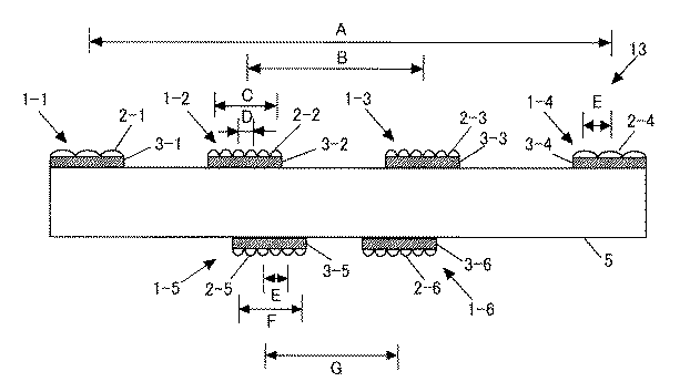
図8においては、上記の2種類の画像データ(基準画像データ、比較画像データ)を、視差計算を実行する処理回路部である視差計算LSI23がリードして、視差計算を実行する構成となっている。このとき、視差計算LSI23に2CHの画像入力があった場合で、内部に視差計算を行うに充分なラインメモリを実装していた場合などには、図8において図示されたようなメモリ(RAM)22を介せず、直接視差計算LSI23に、画像取込LSI21の処理結果の2CH画像を入力してもよい。
In FIG. 8, the above two types of image data (reference image data and comparison image data) are read by the
以上のように、画像の取り込みを実行する画像取込LSI21を、視差計算処理を行う視差計算LSI23と分離して専用で設けることで、従来より存在する視差計算LSIを利用したり、カメラ画像入力の増加等に柔軟に対応できることが可能になる。
As described above, the
以下、追加分
[実施例6]
図9は、一体化した筐体5に画角・焦点距離が異なるカメラ(レンズ+センサ)を複数(三つ以上)持って構成される撮像装置の構成について説明する図である。
図に示すように、この例では1つの筐体5に3つのカメラ1A、1B、1Cが備えられている。カメラ1Aは、レンズ2Aとセンサ3Aとから、カメラ1Bは、レンズ2Bとセンサ3Bとから、カメラ1Cは、レンズ2Cとセンサ3Cとから、それぞれ構成されている。
これにより、視差計算をするためのステレオカメラの基線長を3種類持つことができる。
基線長が長いステレオカメラのセットは遠方をターゲットに、基線長が短いステレオカメラのセットは近傍をターゲットにして測距を行うことで、高精度に近傍〜遠方までをカバーした視差を計算することができる。つまり、図における基線長1のステレオカメラセットが近傍、基線長2のステレオカメラセットが中距離、基線長3のステレオカメラセットが遠方向けの測距を行う。
Hereinafter, additional portion [Example 6]
FIG. 9 is a diagram illustrating the configuration of an imaging apparatus configured by having a plurality of (three or more) cameras (lenses + sensors) having different angles of view and focal lengths in the
As shown in the figure, in this example, one
Thereby, it is possible to have three types of baseline lengths of the stereo camera for performing the parallax calculation.
A set of stereo cameras with a long baseline length is used for far-range targets, and a set of stereo cameras with a short baseline length is used for near-range measurement to calculate parallax that covers from near to far with high accuracy. Can do. In other words, the stereo camera set with the
図10は、焦点距離が異なるために、画角が異なるカメラを複数台つなげたことによって、それぞれの見える撮像範囲がことなることを説明する図である。
前方監視用途で車両に搭載された図10における基線長1のカメラペアで撮像された画像は、たとえば図11に示したようになり、それぞれの画像において、撮像されている物体(たとえば人)のサイズが異なることがわかる。
このような画像ペアに対して視差を計算するためには、エピポーラ幾何などを適用して計算しなければならず、処理時間が膨大にかかる。しかしながら、これらのカメラ画像が理想的なピンホール画像になっていた場合、焦点距離と画角、撮像センサのセンササイズから、設計値に基づく線形の外部パラメータ変換、もしくは拡大・縮小変換によって並行カメラ化することができる。
FIG. 10 is a diagram for explaining that each of the visible imaging ranges is different by connecting a plurality of cameras having different angles of view because the focal lengths are different.
Images captured by a camera pair having a base length of 1 in FIG. 10 mounted on the vehicle for forward monitoring use are as shown in FIG. 11, for example, and in each image, an object (for example, a person) being captured is displayed. You can see that the size is different.
In order to calculate the parallax for such an image pair, it is necessary to calculate by applying epipolar geometry or the like, and the processing time is enormous. However, when these camera images are ideal pinhole images, the parallel camera is converted by linear external parameter conversion based on the design value or enlargement / reduction conversion based on the focal length, angle of view, and sensor size of the image sensor. Can be
図12は、そのような考え方で、一定のカメラ設計値(画角・焦点距離、センササイズ)の画像に、それぞれのカメラ画像を線形変換した例である。図に示したように、画像内で各物体(たとえば人)のサイズが一定になっていることがわかる。
このような場合、平行ステレオ視差計算というシンプルな手法によって、図13のように高精度の視差データを得ることができる。
FIG. 12 is an example in which each camera image is linearly converted into an image of a certain camera design value (view angle / focal length, sensor size) based on such a concept. As shown in the figure, it can be seen that the size of each object (for example, a person) is constant in the image.
In such a case, highly accurate parallax data can be obtained as shown in FIG. 13 by a simple method of parallel stereo parallax calculation.
図14は、本発明の撮像装置により撮像された複数のカメラ画像を処理するための回路構成にかかるブロック図の別例である。
図に示すように、各カメラごとに撮像画像をピンホール画像化するためのキャリブレーションデータをROMなどに持ち、それを利用して、取り込み時に画像をピンホール画像化する。ここで、画像取込LSIは、それぞれのカメラで撮像された画像を、それぞれ理想化されたピンホール画像として出力する手段である。
このピンホール画像化には、LUT(LookUpTable)を利用する、高次多項式を利用する方法などが考えられる。いずれも非線形の変換が必要になる。
FIG. 14 is another example of a block diagram according to a circuit configuration for processing a plurality of camera images captured by the imaging apparatus of the present invention.
As shown in the drawing, calibration data for converting a captured image into a pinhole image for each camera is stored in a ROM or the like, and this is used to convert the image into a pinhole image at the time of capture. Here, the image capture LSI is a means for outputting an image captured by each camera as an idealized pinhole image.
For pinhole imaging, a method using a high-order polynomial using a LUT (LookUpTable) or the like can be considered. Both require non-linear conversion.
図14に基づいて本例における制御動作を説明する。
まず画像線形変換/タイミング制御LSIが、視差計算を実施するペアのカメラ画像をRAMからリードする。このとき、画像線形変換/タイミング制御LSIは、図に示すように、ROMから各カメラの設計データ(焦点距離・画角など)をリードして内部レジスタにリードしており、それに従って画像の線形変換を実施する。
このとき、設計データは、ROMからでなく、外部から内部のレジスタに直接設定する、などの方法をとってもよい。
この設計データに従って、基準となるカメラ設計値を利用した画像に線形変換を行う。線形変換は、3×3のシンプルな行列演算で実行されるのが最も一般的である。線形変換された各カメラの画像データは、それぞれが同じピンホールカメラ画像として扱うことが可能になるので、どのようなカメラペアでも、一つの視差計算アルゴリズムで処理を実行させることができる。
そのため、ロジック部としての視差計算制御LSIは1つのみでよい。本発明によれば、さまざまな画角・焦点距離をもって一つの筐体におさめられた複数のステレオ画像を、時間的な分割をすることで、共通の視差計算ロジックを用いて、計算を実行することができる。
The control operation in this example will be described based on FIG.
First, the image linear conversion / timing control LSI reads a pair of camera images for performing parallax calculation from the RAM. At this time, as shown in the figure, the image linear conversion / timing control LSI reads the design data (focal length, angle of view, etc.) of each camera from the ROM and reads it to the internal register. Perform the conversion.
At this time, the design data may be directly set in an internal register from the outside rather than from the ROM.
In accordance with the design data, linear conversion is performed on an image using a camera design value serving as a reference. Linear transformation is most commonly performed with a simple 3 × 3 matrix operation. Since the linearly transformed image data of each camera can be handled as the same pinhole camera image, any camera pair can execute processing with one parallax calculation algorithm.
Therefore, only one parallax calculation control LSI is required as the logic unit. According to the present invention, a plurality of stereo images contained in one housing with various angles of view and focal lengths are divided in time, and calculation is performed using a common parallax calculation logic. be able to.
このとき、視差計算制御LSIに2CHの画像入力があった場合で、内部に視差計算と画像線形変換を行うに充分なラインメモリを実装していた場合などには、図14において図示されたようなRAMを介せず、直接、画像変形LSI、視差計算処理LSIに、画像取込LSIの処理結果の2CH画像を入力してもよい。
図14の例のように、画像の取り込みを実行するLSI、画像線形変換、視差計算を行う処理LSIをそれぞれ分離して設けると、汎用で存在する視差計算制御LSIを利用したり、カメラ画像入力の増加等に柔軟に対応できることが可能になる。むろん、これらの処理LSIは要求コストとサイズなどに応じて、SOCやSIPなど、ひとつのLSIで構成してもよい。
At this time, when there is a 2CH image input to the parallax calculation control LSI and a line memory sufficient to perform parallax calculation and image linear transformation is mounted inside, as shown in FIG. The 2CH image as the processing result of the image capture LSI may be directly input to the image transformation LSI and the parallax calculation processing LSI without using a RAM.
As shown in the example of FIG. 14, if the LSI for executing image capture, the processing LSI for performing image linear transformation, and parallax calculation are separately provided, a general-purpose parallax calculation control LSI can be used, or camera image input can be performed. It is possible to respond flexibly to the increase in Of course, these processing LSIs may be composed of a single LSI such as SOC or SIP according to the required cost and size.
図14の例のような構成で、カメラが3台あった場合の、処理の概略フローを、図15に示す。各カメラでの撮像・ピンホール画像化処理は、並列に実行され、それぞれの画像が順次DMA転送されてRAMに転送される。そして、図中網掛け部のリード画像転送部によって指示された2つのカメラ画像ペアが、ステレオ計算用としてRAMよりリードされる。
リードされた画像は、図11〜図13に示したような線形変換処理が施され、それぞれが一定のカメラ設計値の撮像画像化され、視差計算が実行される。
このとき、リードされる画像は、ステレオカメラのペアになる2つの画像である。このとき、最も簡単な方法は、すべてのステレオカメラのペアを同じ時間分割で処理させることである。たとえば、測距するステレオカメラのセットを3つ用意する。ステレオカメラ1は近傍、ステレオカメラ2は中距離、ステレオカメラ3は遠方、を測距するものとする。
このとき、同様に時間分割して視差計算を実行させると、図16(A)のようになる。しかし、一般に、近傍の距離の方が、緊急を有することが多いため、頻度を高く計算させなければならないことが多い。そのような場合は、図16(B)のように処理を実行させてもよい。
FIG. 15 shows a schematic processing flow when there are three cameras in the configuration as in the example of FIG. The imaging / pinhole imaging processing in each camera is executed in parallel, and each image is sequentially DMA transferred and transferred to the RAM. Then, two camera image pairs instructed by the read image transfer unit of the shaded part in the figure are read from the RAM for stereo calculation.
The read image is subjected to linear conversion processing as shown in FIGS. 11 to 13, and each is converted into a captured image of a certain camera design value, and parallax calculation is executed.
At this time, the images to be read are two images that form a pair of stereo cameras. At this time, the simplest method is to process all stereo camera pairs in the same time division. For example, three sets of stereo cameras for distance measurement are prepared. The
At this time, when the parallax calculation is executed by time-division similarly, the result is as shown in FIG. However, in general, the distance in the vicinity often has an urgent situation, and thus the frequency must often be calculated. In such a case, the process may be executed as shown in FIG.
また、図2に示したように、各ステレオカメラごとに測距範囲と画角が異なるが、それらには重複する部分ができる。これを図示したのが、図17である。
ステレオカメラのセット(基線長のセット)が3つできるとし、それぞれの測距範囲の重複を表したのが、図17の右部分の測距範囲における網掛け部である。また一般的に遠方に行くほど撮像される画角範囲は小さくなる。図17の左部分は、線形変換前の各ステレオカメラの対応画角範囲を図示したものである。
ここで、この重複範囲に関して、どのようにして距離を出力するのか、が問題になる。
これに対しては、たとえば下記のような基準で、距離を決定することができる。
(1)重複エリアはどのステレオカメラが担当させるかを決定しておく:処理をシンプル化し、負荷低減できる。
(2)先に計算された距離を優先させる:距離をできる限りはやくに知りたい場合に有効
(3)計算された距離を、選択して決定させる:計算結果に信頼度や重みなどをつけ、より信用できる計算結果を利用したい場合に有効
(4)計算された距離の平均を使う:重複されたエリアは各ステレオカメラのペアが出るごとに平均化されて決定されるため、ノイズ成分を除去して安定して使うことができる。
(5)線形変換前の画像解像度の高い方のステレオカメラの結果を利用する:解像度が高いということは、物理的なつくりとして、理論的により信頼度が高く計算できるはずであり、そちらを優先する
Further, as shown in FIG. 2, the distance measurement range and the angle of view are different for each stereo camera, but there are overlapping portions. This is illustrated in FIG.
Assuming that three sets of stereo cameras (base line length sets) can be formed, the overlapping of the respective distance measurement ranges represents the shaded portion in the distance measurement range in the right part of FIG. In general, the field angle range to be imaged becomes smaller as the distance increases. The left part of FIG. 17 illustrates the corresponding field angle range of each stereo camera before linear conversion.
Here, how to output the distance with respect to the overlapping range becomes a problem.
For this, for example, the distance can be determined based on the following criteria.
(1) Decide which stereo camera will handle the overlapping area: the process can be simplified and the load can be reduced.
(2) Prioritize the previously calculated distance: Effective when you want to know the distance as soon as possible (3) Select and determine the calculated distance: Add reliability and weight to the calculation result, Useful when you want to use more reliable calculation results (4) Use the average of the calculated distance: Since the overlapping area is determined by averaging each pair of stereo cameras, noise components are removed And can be used stably.
(5) Use the result of stereo camera with higher image resolution before linear conversion: Higher resolution should be able to be calculated with higher reliability theoretically as a physical structure. Do
また、このような距離計算を実行させておきつつ、各ステレオカメラの測距結果が計算されるごとに、たとえば車載の前方監視カメラとして使用している場合など、処理として非常に危険と設定されていた距離範囲に物体があると検出された場合、その計算結果を優先させてもよい。
たとえば、上記の(1)のような処理形態でステレオカメラ2に1m以上の距離を担当させておきつつ、ステレオカメラ2で数十センチの距離のものが画像の端エリアに突然出てきた場合などは、割り込み車や横断者などが現れたと考えられるので、そのような場合は、この結果を優先させるほうがよいと考えられる。
図7で示したカメラの向きが異なる構成は、本例においても同様に実施することができる。
In addition, each time a distance measurement result of each stereo camera is calculated while performing such distance calculation, for example, when used as a vehicle-mounted front monitoring camera, the process is set to be extremely dangerous. When it is detected that there is an object in the distance range, the calculation result may be prioritized.
For example, when the
The configuration in which the orientation of the camera shown in FIG. 7 is different can be similarly implemented in this example.
1、1−1、1−2、1−3、1−4、1−5、1−6:複眼カメラ
1’:複数のセンサを含む複眼カメラ
2、2−1、2−2、2−3、2−4、2−5、2−6:レンズアレイ
3、3−1、3−2、3−3、3−4、3−5、3−6:センサ
3a,3b,3c,3d,3e:1つの基板に設けられた複数のセンサ
4:基板
5:筐体(カメラユニット)
6−1、6−2:複眼でないカメラ
7−1、7−2:レンズ
8−1、8−2:センサ
10、11、12、13:撮像装置
21:画像取込LSI
22:メモリ(RAM)
23:視差計算LSI
1, 1-1, 1-2, 1-3, 1-4, 1-5, 1-6:
6-1 and 6-2: Cameras that are not compound eyes 7-1 and 7-2: Lenses 8-1 and 8-2:
22: Memory (RAM)
23: Parallax calculation LSI
Claims (10)
前記複数のカメラのうち少なくとも1つは、同一平面上に配置された複数のレンズを有するレンズアレイとセンサとを備えた複眼カメラであり、
前記複眼カメラによって撮像される複数の個眼像を用いて第1の頻度において第1の基線長で近距離における測距のための視差を計算し、
少なくとも前記複眼カメラとは異なるカメラを含む2つのカメラによってそれぞれ撮像される画像を用いて前記第1の頻度よりも少ない第2の頻度において前記第1の基線長よりも長い第2の基線長で遠距離における測距のための視差を計算することを特徴とする撮像装置。 A plurality of cameras are mounted in fixed in one housing, a combination of any two cameras of the plurality of cameras, by using an image captured while changing the group line length you calculate parallax in imaging device ranging,
At least one of the plurality of cameras is a compound eye camera including a lens array having a plurality of lenses arranged on the same plane and a sensor,
The disparity for the distance measurement in the short distance at the first base length was calculated in the first frequency by using a plurality of single-eye image captured by the compound-eye camera,
In at least the second base length longer than said first base length in a second frequency less than the first frequency by using the images captured respectively by the two cameras, including a different camera than the compound eye camera imaging device, which comprises a calculation parallax for distance measurement in the far.
前記センサが、一つの基板に設けられた複数のセンサから構成されていることを特徴とする撮像装置。 The imaging device according to claim 1,
An imaging apparatus , wherein the sensor is composed of a plurality of sensors provided on one substrate .
前記複数のカメラがレンズとセンサとを備え、各カメラの画角及び焦点距離がそれぞれ異なることを特徴とする撮像装置。 The imaging device according to claim 1 ,
An imaging apparatus, wherein the plurality of cameras includes a lens and a sensor, and each camera has a different angle of view and focal length .
各カメラ毎に撮像画像をピンホール画像化するためのキャリブレーションデータを持ち、それぞれのカメラで撮像された画像を、それぞれピンホール画像化して出力する手段を有していることを特徴とする撮像装置。 The imaging device according to claim 3 .
Each camera has calibration data for converting a captured image into a pinhole image, and has means for converting the image captured by each camera into a pinhole image and outputting the image. apparatus.
それぞれのカメラで撮像された画像を、統一された画像サイズに拡大・縮小処理を施すロジック部を有していることを特徴とする撮像装置。 The imaging device according to claim 3 .
An image pickup apparatus comprising: a logic unit that performs an enlargement / reduction process on an image picked up by each camera to a unified image size .
複数の基線長のカメラの距離計算結果を保存しておき、後段の処理で利用する同一物体の距離を、それらの結果の中から選択可能としたことを特徴とする撮像装置。 The imaging device according to claim 1 ,
An imaging apparatus characterized by storing distance calculation results of a plurality of baseline length cameras, and selecting a distance of the same object to be used in subsequent processing from among the results .
複数の基線長のカメラの距離計算結果を保存しておき、後段の処理で利用する距離を、それまでの結果の平均によって算出することを特徴とする撮像装置。 The imaging device according to claim 1 ,
An imaging apparatus characterized by storing distance calculation results of a plurality of baseline length cameras and calculating a distance to be used in subsequent processing by averaging the results so far .
前記複数のカメラのうち、1つ以上のカメラの設置方向が他のカメラと異なることを特徴とする撮像装置。 In the imaging device according to any one of claims 1 to 7 ,
An imaging apparatus, wherein an installation direction of one or more cameras among the plurality of cameras is different from other cameras .
取得される複数のカメラ画像の視差計算処理を、それぞれの画像を分離・統合する回路部と、視差計算を行う処理回路部とに分けて実行することを特徴とする撮像装置。 In the imaging device according to any one of claims 1 to 8 ,
An imaging apparatus that executes parallax calculation processing of a plurality of acquired camera images separately for a circuit unit that separates and integrates each image and a processing circuit unit that performs parallax calculation .
Priority Applications (2)
| Application Number | Priority Date | Filing Date | Title |
|---|---|---|---|
| JP2010277395A JP5776173B2 (en) | 2010-03-01 | 2010-12-13 | Imaging device and distance measuring device |
| US13/025,890 US8654196B2 (en) | 2010-03-01 | 2011-02-11 | Image pickup apparatus and rangefinder, with altering baseline lengths for parallax computation obtained by combining any two of a plurality of cameras |
Applications Claiming Priority (3)
| Application Number | Priority Date | Filing Date | Title |
|---|---|---|---|
| JP2010044168 | 2010-03-01 | ||
| JP2010044168 | 2010-03-01 | ||
| JP2010277395A JP5776173B2 (en) | 2010-03-01 | 2010-12-13 | Imaging device and distance measuring device |
Publications (2)
| Publication Number | Publication Date |
|---|---|
| JP2011203238A JP2011203238A (en) | 2011-10-13 |
| JP5776173B2 true JP5776173B2 (en) | 2015-09-09 |
Family
ID=44505078
Family Applications (1)
| Application Number | Title | Priority Date | Filing Date |
|---|---|---|---|
| JP2010277395A Active JP5776173B2 (en) | 2010-03-01 | 2010-12-13 | Imaging device and distance measuring device |
Country Status (2)
| Country | Link |
|---|---|
| US (1) | US8654196B2 (en) |
| JP (1) | JP5776173B2 (en) |
Cited By (1)
| Publication number | Priority date | Publication date | Assignee | Title |
|---|---|---|---|---|
| KR102507184B1 (en) | 2022-06-17 | 2023-03-09 | 한국기계연구원 | Micro lens array and method for manufacturing the same |
Families Citing this family (72)
| Publication number | Priority date | Publication date | Assignee | Title |
|---|---|---|---|---|
| US11792538B2 (en) | 2008-05-20 | 2023-10-17 | Adeia Imaging Llc | Capturing and processing of images including occlusions focused on an image sensor by a lens stack array |
| US8866920B2 (en) | 2008-05-20 | 2014-10-21 | Pelican Imaging Corporation | Capturing and processing of images using monolithic camera array with heterogeneous imagers |
| WO2011063347A2 (en) | 2009-11-20 | 2011-05-26 | Pelican Imaging Corporation | Capturing and processing of images using monolithic camera array with heterogeneous imagers |
| US8878950B2 (en) | 2010-12-14 | 2014-11-04 | Pelican Imaging Corporation | Systems and methods for synthesizing high resolution images using super-resolution processes |
| KR101852811B1 (en) * | 2011-01-05 | 2018-04-27 | 엘지전자 주식회사 | Display device and method for controlling thereof |
| JP5910740B2 (en) * | 2011-07-05 | 2016-04-27 | オムロン株式会社 | Method and apparatus for projective space monitoring |
| JP5762211B2 (en) * | 2011-08-11 | 2015-08-12 | キヤノン株式会社 | Image processing apparatus, image processing method, and program |
| KR101316433B1 (en) * | 2011-09-14 | 2013-10-08 | 현대자동차주식회사 | System for providing around information of vehicle and method thereof |
| US8542933B2 (en) | 2011-09-28 | 2013-09-24 | Pelican Imaging Corporation | Systems and methods for decoding light field image files |
| JP6102930B2 (en) | 2011-10-14 | 2017-03-29 | オムロン株式会社 | Method and apparatus for projective space monitoring |
| WO2013126578A1 (en) | 2012-02-21 | 2013-08-29 | Pelican Imaging Corporation | Systems and methods for the manipulation of captured light field image data |
| JP6197291B2 (en) | 2012-03-21 | 2017-09-20 | 株式会社リコー | Compound eye camera device and vehicle equipped with the same |
| JP2015534734A (en) | 2012-06-28 | 2015-12-03 | ペリカン イメージング コーポレイション | System and method for detecting defective camera arrays, optical arrays, and sensors |
| JP5929553B2 (en) | 2012-06-28 | 2016-06-08 | ソニー株式会社 | Image processing apparatus, imaging apparatus, image processing method, and program |
| US20140002674A1 (en) | 2012-06-30 | 2014-01-02 | Pelican Imaging Corporation | Systems and Methods for Manufacturing Camera Modules Using Active Alignment of Lens Stack Arrays and Sensors |
| WO2014031795A1 (en) | 2012-08-21 | 2014-02-27 | Pelican Imaging Corporation | Systems and methods for parallax detection and correction in images captured using array cameras |
| CN104685513B (en) | 2012-08-23 | 2018-04-27 | 派力肯影像公司 | According to the high-resolution estimation of the feature based of the low-resolution image caught using array source |
| CN104685860A (en) | 2012-09-28 | 2015-06-03 | 派力肯影像公司 | Generating images from light fields utilizing virtual viewpoints |
| WO2014054752A1 (en) * | 2012-10-04 | 2014-04-10 | アルプス電気株式会社 | Image processing device and device for monitoring area in front of vehicle |
| JP2015232442A (en) * | 2012-10-04 | 2015-12-24 | アルプス電気株式会社 | Image processor and vehicle front monitoring device |
| US9386298B2 (en) * | 2012-11-08 | 2016-07-05 | Leap Motion, Inc. | Three-dimensional image sensors |
| FR2999729B1 (en) * | 2012-12-14 | 2015-01-16 | Astrium Sas | OPTICAL FOCUSING OF AN IMAGE INPUT INSTRUMENT |
| US8866912B2 (en) | 2013-03-10 | 2014-10-21 | Pelican Imaging Corporation | System and methods for calibration of an array camera using a single captured image |
| WO2014159779A1 (en) | 2013-03-14 | 2014-10-02 | Pelican Imaging Corporation | Systems and methods for reducing motion blur in images or video in ultra low light with array cameras |
| US10122993B2 (en) | 2013-03-15 | 2018-11-06 | Fotonation Limited | Autofocus system for a conventional camera that uses depth information from an array camera |
| US9497429B2 (en) | 2013-03-15 | 2016-11-15 | Pelican Imaging Corporation | Extended color processing on pelican array cameras |
| EP2973476B1 (en) | 2013-03-15 | 2025-02-26 | Adeia Imaging LLC | Systems and methods for stereo imaging with camera arrays |
| WO2015012280A1 (en) * | 2013-07-24 | 2015-01-29 | コニカミノルタ株式会社 | Sight line detection device |
| JP2015060053A (en) * | 2013-09-18 | 2015-03-30 | 株式会社東芝 | Solid-state imaging device, control device, and control program |
| WO2015048694A2 (en) | 2013-09-27 | 2015-04-02 | Pelican Imaging Corporation | Systems and methods for depth-assisted perspective distortion correction |
| US10119808B2 (en) | 2013-11-18 | 2018-11-06 | Fotonation Limited | Systems and methods for estimating depth from projected texture using camera arrays |
| WO2015081279A1 (en) | 2013-11-26 | 2015-06-04 | Pelican Imaging Corporation | Array camera configurations incorporating multiple constituent array cameras |
| DE112014005645A5 (en) | 2013-12-13 | 2016-09-08 | Fts Computertechnik Gmbh | Method and device for observing the environment of a vehicle |
| US20150185308A1 (en) * | 2014-01-02 | 2015-07-02 | Katsuhiro Wada | Image processing apparatus and image processing method, image pickup apparatus and control method thereof, and program |
| WO2015134996A1 (en) | 2014-03-07 | 2015-09-11 | Pelican Imaging Corporation | System and methods for depth regularization and semiautomatic interactive matting using rgb-d images |
| WO2015159791A1 (en) * | 2014-04-16 | 2015-10-22 | コニカミノルタ株式会社 | Distance measuring device and distance measuring method |
| JP2016001464A (en) | 2014-05-19 | 2016-01-07 | 株式会社リコー | PROCESSING DEVICE, PROCESSING SYSTEM, PROCESSING PROGRAM, AND PROCESSING METHOD |
| WO2016054089A1 (en) | 2014-09-29 | 2016-04-07 | Pelican Imaging Corporation | Systems and methods for dynamic calibration of array cameras |
| US10008027B1 (en) | 2014-10-20 | 2018-06-26 | Henry Harlyn Baker | Techniques for determining a three-dimensional representation of a surface of an object from a set of images |
| WO2016106694A1 (en) | 2014-12-31 | 2016-07-07 | SZ DJI Technology Co., Ltd. | System and method for adjusting a baseline of an imaging system with microlens array |
| US9794543B2 (en) | 2015-03-02 | 2017-10-17 | Ricoh Company, Ltd. | Information processing apparatus, image capturing apparatus, control system applicable to moveable apparatus, information processing method, and storage medium of program of method |
| JP2016217944A (en) * | 2015-05-22 | 2016-12-22 | シャープ株式会社 | Measuring device and measuring method |
| GB2541101A (en) * | 2015-06-23 | 2017-02-08 | Bosch Gmbh Robert | Method and camera system for determining the distance of objects in relation to a vehicle |
| EP3352134B1 (en) | 2015-09-15 | 2023-10-11 | Ricoh Company, Ltd. | Image processing device, object recognition device, device control system, image processing method, and program |
| JP6677474B2 (en) * | 2015-09-29 | 2020-04-08 | 日立オートモティブシステムズ株式会社 | Perimeter recognition device |
| WO2017090326A1 (en) | 2015-11-27 | 2017-06-01 | 株式会社リコー | Image processing device, image pickup device, apparatus control system, distribution data generation method, and program |
| JP6597792B2 (en) | 2015-11-30 | 2019-10-30 | 株式会社リコー | Image processing apparatus, object recognition apparatus, device control system, image processing method and program |
| JP6922169B2 (en) | 2016-08-24 | 2021-08-18 | ソニーグループ株式会社 | Information processing equipment and methods, vehicles, and information processing systems |
| CN111213361B (en) * | 2017-10-20 | 2022-04-26 | 索尼公司 | Information processing device, information processing method, program, and interchangeable lens |
| JP7256623B2 (en) * | 2018-09-27 | 2023-04-12 | 株式会社Subaru | Vehicle stereo camera device |
| JP7202120B2 (en) * | 2018-09-27 | 2023-01-11 | 株式会社Subaru | Driving support device |
| BR112022004811A2 (en) | 2019-09-17 | 2022-06-21 | Boston Polarimetrics Inc | Systems and methods for surface modeling using polarization indications |
| CN114746717A (en) | 2019-10-07 | 2022-07-12 | 波士顿偏振测定公司 | System and method for surface normal sensing using polarization |
| KR20230116068A (en) | 2019-11-30 | 2023-08-03 | 보스턴 폴라리메트릭스, 인크. | System and method for segmenting transparent objects using polarization signals |
| WO2021154386A1 (en) | 2020-01-29 | 2021-08-05 | Boston Polarimetrics, Inc. | Systems and methods for characterizing object pose detection and measurement systems |
| KR20220133973A (en) | 2020-01-30 | 2022-10-05 | 인트린식 이노베이션 엘엘씨 | Systems and methods for synthesizing data to train statistical models for different imaging modalities, including polarized images |
| US11953700B2 (en) | 2020-05-27 | 2024-04-09 | Intrinsic Innovation Llc | Multi-aperture polarization optical systems using beam splitters |
| JP7369094B2 (en) * | 2020-05-29 | 2023-10-25 | 株式会社日立製作所 | Distance measurement system and distance measurement method |
| JPWO2022123723A1 (en) * | 2020-12-10 | 2022-06-16 | ||
| WO2022164337A1 (en) * | 2021-01-27 | 2022-08-04 | Олег Александрович СЕРЕБРЕННИКОВ | Method for measuring the position of and distance to a light stimulus |
| US12069227B2 (en) | 2021-03-10 | 2024-08-20 | Intrinsic Innovation Llc | Multi-modal and multi-spectral stereo camera arrays |
| US12020455B2 (en) | 2021-03-10 | 2024-06-25 | Intrinsic Innovation Llc | Systems and methods for high dynamic range image reconstruction |
| US11954886B2 (en) | 2021-04-15 | 2024-04-09 | Intrinsic Innovation Llc | Systems and methods for six-degree of freedom pose estimation of deformable objects |
| US11290658B1 (en) | 2021-04-15 | 2022-03-29 | Boston Polarimetrics, Inc. | Systems and methods for camera exposure control |
| US12067746B2 (en) | 2021-05-07 | 2024-08-20 | Intrinsic Innovation Llc | Systems and methods for using computer vision to pick up small objects |
| JP2022184138A (en) * | 2021-05-31 | 2022-12-13 | キヤノン株式会社 | Image processing device, imaging device, control method, and program |
| US12175741B2 (en) | 2021-06-22 | 2024-12-24 | Intrinsic Innovation Llc | Systems and methods for a vision guided end effector |
| US12340538B2 (en) | 2021-06-25 | 2025-06-24 | Intrinsic Innovation Llc | Systems and methods for generating and using visual datasets for training computer vision models |
| US12172310B2 (en) | 2021-06-29 | 2024-12-24 | Intrinsic Innovation Llc | Systems and methods for picking objects using 3-D geometry and segmentation |
| US11689813B2 (en) | 2021-07-01 | 2023-06-27 | Intrinsic Innovation Llc | Systems and methods for high dynamic range imaging using crossed polarizers |
| US12293535B2 (en) | 2021-08-03 | 2025-05-06 | Intrinsic Innovation Llc | Systems and methods for training pose estimators in computer vision |
| DE102023205343A1 (en) * | 2023-06-07 | 2024-12-12 | Tripleye Gmbh | Device for spatial image capture of an environment moving relative to the device and operating method therefor |
Family Cites Families (16)
| Publication number | Priority date | Publication date | Assignee | Title |
|---|---|---|---|---|
| JPH0798429A (en) * | 1993-09-28 | 1995-04-11 | Fuji Film Micro Device Kk | Range finder |
| JPH07191146A (en) * | 1993-12-24 | 1995-07-28 | Mitsubishi Electric Corp | Distance measuring device |
| JPH08219774A (en) * | 1995-02-15 | 1996-08-30 | Omron Corp | Photoelectric switch |
| US6009189A (en) * | 1996-08-16 | 1999-12-28 | Schaack; David F. | Apparatus and method for making accurate three-dimensional size measurements of inaccessible objects |
| JPH1139596A (en) | 1997-07-17 | 1999-02-12 | Fuji Heavy Ind Ltd | Outside monitoring device |
| EP1418766A3 (en) * | 1998-08-28 | 2010-03-24 | Imax Corporation | Method and apparatus for processing images |
| JP2003143459A (en) * | 2001-11-02 | 2003-05-16 | Canon Inc | Compound eye imaging system and apparatus equipped with the same |
| US7336296B2 (en) * | 2003-10-10 | 2008-02-26 | International Business Machines Corporation | System and method for providing position-independent pose estimation |
| US20060055811A1 (en) * | 2004-09-14 | 2006-03-16 | Frtiz Bernard S | Imaging system having modules with adaptive optical elements |
| US7855752B2 (en) * | 2006-07-31 | 2010-12-21 | Hewlett-Packard Development Company, L.P. | Method and system for producing seamless composite images having non-uniform resolution from a multi-imager system |
| JP4448844B2 (en) | 2006-11-22 | 2010-04-14 | 富士フイルム株式会社 | Compound eye imaging device |
| JP2008286527A (en) * | 2007-05-15 | 2008-11-27 | Panasonic Corp | Compound eye rangefinder |
| JP2009055554A (en) * | 2007-08-29 | 2009-03-12 | Fujifilm Corp | Flexible imaging device equipped with multiple imaging elements |
| US20100053414A1 (en) | 2008-01-11 | 2010-03-04 | Satoshi Tamaki | Compound eye camera module |
| JP4423347B2 (en) * | 2008-02-26 | 2010-03-03 | パナソニック株式会社 | Inspection method and inspection apparatus for compound eye distance measuring apparatus and chart used therefor |
| US8390083B2 (en) * | 2009-09-04 | 2013-03-05 | Analog Devices, Inc. | System with recessed sensing or processing elements |
-
2010
- 2010-12-13 JP JP2010277395A patent/JP5776173B2/en active Active
-
2011
- 2011-02-11 US US13/025,890 patent/US8654196B2/en active Active
Cited By (1)
| Publication number | Priority date | Publication date | Assignee | Title |
|---|---|---|---|---|
| KR102507184B1 (en) | 2022-06-17 | 2023-03-09 | 한국기계연구원 | Micro lens array and method for manufacturing the same |
Also Published As
| Publication number | Publication date |
|---|---|
| US8654196B2 (en) | 2014-02-18 |
| US20110211068A1 (en) | 2011-09-01 |
| JP2011203238A (en) | 2011-10-13 |
Similar Documents
| Publication | Publication Date | Title |
|---|---|---|
| JP5776173B2 (en) | Imaging device and distance measuring device | |
| JP5273356B2 (en) | Compound eye image input device and distance measuring device using the same | |
| JP7038345B2 (en) | Camera parameter set calculation method, camera parameter set calculation program and camera parameter set calculation device | |
| EP2058762B1 (en) | Method and apparatus for generating bird's-eye image | |
| US20200342243A1 (en) | Method for estimating distance to an object via a vehicular vision system | |
| JP4414661B2 (en) | Stereo adapter and range image input device using the same | |
| JP5760559B2 (en) | Stereo camera device and parallax image generation method | |
| JP6565188B2 (en) | Parallax value deriving apparatus, device control system, moving body, robot, parallax value deriving method, and program | |
| JP2018191275A (en) | Camera parameter set calculation method, camera parameter set calculation program and camera parameter set calculation device | |
| WO2019123840A1 (en) | Imaging device, imaging system, and display system | |
| WO2017123477A1 (en) | Vehicle based radar upsampling | |
| US10992920B2 (en) | Stereo image processing device | |
| JP2014503408A (en) | Method and apparatus for processing image information of two sensors suitable for image detection in a stereo sensor system | |
| US9813694B2 (en) | Disparity value deriving device, equipment control system, movable apparatus, robot, and disparity value deriving method | |
| JP2012156672A (en) | Vehicle periphery monitoring device | |
| WO2016063545A1 (en) | Stereo camera apparatus and vehicle provided with stereo camera apparatus | |
| US20230308598A1 (en) | Image processing device, image processing method, and storage medium | |
| JP5455033B2 (en) | Distance image input device and outside monitoring device | |
| JP2019102888A (en) | Camera module | |
| WO2014054752A1 (en) | Image processing device and device for monitoring area in front of vehicle | |
| JP2011024079A (en) | Peripheral display device | |
| JP2007295113A (en) | Imaging device | |
| JP6983740B2 (en) | Stereo camera system and distance measurement method | |
| JP2011077806A (en) | Vehicle surroundings monitoring device | |
| JP2016009427A (en) | Image processing apparatus, image processing method, and device control system |
Legal Events
| Date | Code | Title | Description |
|---|---|---|---|
| A621 | Written request for application examination |
Free format text: JAPANESE INTERMEDIATE CODE: A621 Effective date: 20131111 |
|
| A977 | Report on retrieval |
Free format text: JAPANESE INTERMEDIATE CODE: A971007 Effective date: 20140404 |
|
| A131 | Notification of reasons for refusal |
Free format text: JAPANESE INTERMEDIATE CODE: A131 Effective date: 20140415 |
|
| A521 | Request for written amendment filed |
Free format text: JAPANESE INTERMEDIATE CODE: A523 Effective date: 20140611 |
|
| A131 | Notification of reasons for refusal |
Free format text: JAPANESE INTERMEDIATE CODE: A131 Effective date: 20141216 |
|
| A521 | Request for written amendment filed |
Free format text: JAPANESE INTERMEDIATE CODE: A523 Effective date: 20150128 |
|
| TRDD | Decision of grant or rejection written | ||
| A01 | Written decision to grant a patent or to grant a registration (utility model) |
Free format text: JAPANESE INTERMEDIATE CODE: A01 Effective date: 20150609 |
|
| A61 | First payment of annual fees (during grant procedure) |
Free format text: JAPANESE INTERMEDIATE CODE: A61 Effective date: 20150622 |
|
| R151 | Written notification of patent or utility model registration |
Ref document number: 5776173 Country of ref document: JP Free format text: JAPANESE INTERMEDIATE CODE: R151 |