JP5765310B2 - Body front structure - Google Patents
Body front structure Download PDFInfo
- Publication number
- JP5765310B2 JP5765310B2 JP2012203000A JP2012203000A JP5765310B2 JP 5765310 B2 JP5765310 B2 JP 5765310B2 JP 2012203000 A JP2012203000 A JP 2012203000A JP 2012203000 A JP2012203000 A JP 2012203000A JP 5765310 B2 JP5765310 B2 JP 5765310B2
- Authority
- JP
- Japan
- Prior art keywords
- vehicle body
- front side
- width direction
- vehicle
- vehicle width
- Prior art date
- Legal status (The legal status is an assumption and is not a legal conclusion. Google has not performed a legal analysis and makes no representation as to the accuracy of the status listed.)
- Expired - Fee Related
Links
- 239000011347 resin Substances 0.000 claims description 17
- 229920005989 resin Polymers 0.000 claims description 17
- 230000005540 biological transmission Effects 0.000 claims description 9
- 239000002184 metal Substances 0.000 claims description 9
- 229910052751 metal Inorganic materials 0.000 claims description 9
- 125000006850 spacer group Chemical group 0.000 description 32
- 230000004888 barrier function Effects 0.000 description 13
- 230000006835 compression Effects 0.000 description 7
- 238000007906 compression Methods 0.000 description 7
- 238000010521 absorption reaction Methods 0.000 description 5
- 230000005764 inhibitory process Effects 0.000 description 4
- 230000002787 reinforcement Effects 0.000 description 3
- 238000003466 welding Methods 0.000 description 3
- XEEYBQQBJWHFJM-UHFFFAOYSA-N Iron Chemical compound [Fe] XEEYBQQBJWHFJM-UHFFFAOYSA-N 0.000 description 2
- 239000000853 adhesive Substances 0.000 description 2
- 230000001070 adhesive effect Effects 0.000 description 2
- 230000000694 effects Effects 0.000 description 2
- 230000002452 interceptive effect Effects 0.000 description 2
- 229910052742 iron Inorganic materials 0.000 description 1
- 230000003014 reinforcing effect Effects 0.000 description 1
- 230000009466 transformation Effects 0.000 description 1
Images


Classifications
-
- B—PERFORMING OPERATIONS; TRANSPORTING
- B60—VEHICLES IN GENERAL
- B60R—VEHICLES, VEHICLE FITTINGS, OR VEHICLE PARTS, NOT OTHERWISE PROVIDED FOR
- B60R19/00—Wheel guards; Radiator guards, e.g. grilles; Obstruction removers; Fittings damping bouncing force in collisions
- B60R19/02—Bumpers, i.e. impact receiving or absorbing members for protecting vehicles or fending off blows from other vehicles or objects
-
- B—PERFORMING OPERATIONS; TRANSPORTING
- B62—LAND VEHICLES FOR TRAVELLING OTHERWISE THAN ON RAILS
- B62D—MOTOR VEHICLES; TRAILERS
- B62D21/00—Understructures, i.e. chassis frame on which a vehicle body may be mounted
- B62D21/15—Understructures, i.e. chassis frame on which a vehicle body may be mounted having impact absorbing means, e.g. a frame designed to permanently or temporarily change shape or dimension upon impact with another body
- B62D21/152—Front or rear frames
-
- B—PERFORMING OPERATIONS; TRANSPORTING
- B60—VEHICLES IN GENERAL
- B60R—VEHICLES, VEHICLE FITTINGS, OR VEHICLE PARTS, NOT OTHERWISE PROVIDED FOR
- B60R19/00—Wheel guards; Radiator guards, e.g. grilles; Obstruction removers; Fittings damping bouncing force in collisions
- B60R19/02—Bumpers, i.e. impact receiving or absorbing members for protecting vehicles or fending off blows from other vehicles or objects
- B60R19/03—Bumpers, i.e. impact receiving or absorbing members for protecting vehicles or fending off blows from other vehicles or objects characterised by material, e.g. composite
-
- B—PERFORMING OPERATIONS; TRANSPORTING
- B60—VEHICLES IN GENERAL
- B60R—VEHICLES, VEHICLE FITTINGS, OR VEHICLE PARTS, NOT OTHERWISE PROVIDED FOR
- B60R19/00—Wheel guards; Radiator guards, e.g. grilles; Obstruction removers; Fittings damping bouncing force in collisions
- B60R19/02—Bumpers, i.e. impact receiving or absorbing members for protecting vehicles or fending off blows from other vehicles or objects
- B60R19/24—Arrangements for mounting bumpers on vehicles
-
- B—PERFORMING OPERATIONS; TRANSPORTING
- B62—LAND VEHICLES FOR TRAVELLING OTHERWISE THAN ON RAILS
- B62D—MOTOR VEHICLES; TRAILERS
- B62D25/00—Superstructure or monocoque structure sub-units; Parts or details thereof not otherwise provided for
- B62D25/08—Front or rear portions
- B62D25/082—Engine compartments
-
- B—PERFORMING OPERATIONS; TRANSPORTING
- B60—VEHICLES IN GENERAL
- B60R—VEHICLES, VEHICLE FITTINGS, OR VEHICLE PARTS, NOT OTHERWISE PROVIDED FOR
- B60R19/00—Wheel guards; Radiator guards, e.g. grilles; Obstruction removers; Fittings damping bouncing force in collisions
- B60R19/02—Bumpers, i.e. impact receiving or absorbing members for protecting vehicles or fending off blows from other vehicles or objects
- B60R19/24—Arrangements for mounting bumpers on vehicles
- B60R19/26—Arrangements for mounting bumpers on vehicles comprising yieldable mounting means
- B60R19/34—Arrangements for mounting bumpers on vehicles comprising yieldable mounting means destroyed upon impact, e.g. one-shot type
-
- B—PERFORMING OPERATIONS; TRANSPORTING
- B60—VEHICLES IN GENERAL
- B60R—VEHICLES, VEHICLE FITTINGS, OR VEHICLE PARTS, NOT OTHERWISE PROVIDED FOR
- B60R19/00—Wheel guards; Radiator guards, e.g. grilles; Obstruction removers; Fittings damping bouncing force in collisions
- B60R19/02—Bumpers, i.e. impact receiving or absorbing members for protecting vehicles or fending off blows from other vehicles or objects
- B60R2019/026—Buffers, i.e. bumpers of limited extent
Landscapes
- Engineering & Computer Science (AREA)
- Mechanical Engineering (AREA)
- Chemical & Material Sciences (AREA)
- Combustion & Propulsion (AREA)
- Transportation (AREA)
- Body Structure For Vehicles (AREA)
Description
本発明は、車体前部構造に関する。 The present invention relates to a vehicle body front structure.
フロントサイドメンバの側部に、車体前方外側に向かって延びる補強メンバを、クラッシュボックスの後端部よりも車体後方側に設けた車体前部構造は、従来から提案されている(例えば、特許文献1参照)。 A vehicle body front structure in which a reinforcing member extending toward the front outer side of the vehicle body is provided on the side of the front side member on the vehicle rear side of the rear end portion of the crash box has been conventionally proposed (for example, Patent Documents). 1).
ところで、フロントサイドメンバよりも車幅方向外側で前面衝突(微小ラップ衝突)した場合には、車両の変形を抑制するために、その車両に対して横力(車幅方向で衝突側とは反対側へ向かう力)を効率よく発生させることが望まれる。 By the way, in the case of a frontal collision (a minute lap collision) outside the front side member in the vehicle width direction, in order to suppress deformation of the vehicle, a lateral force (opposite to the collision side in the vehicle width direction) is applied to the vehicle. It is desirable to efficiently generate a force toward the side.
そこで、本発明は、微小ラップ衝突時に車両に対して横力を効率よく発生させられる車体前部構造を得ることを目的とする。 Therefore, an object of the present invention is to obtain a vehicle body front structure that can efficiently generate a lateral force against a vehicle at the time of a minute lap collision.
上記の目的を達成するために、本発明に係る請求項1に記載の車体前部構造は、車体前部における車幅方向外側に車体前後方向に沿って配置されたフロントサイドメンバと、前記フロントサイドメンバの外側壁に、該外側壁よりも車幅方向外側へ突出するように、かつ平面視で前記フロントサイドメンバの車幅方向内側に配置されたパワーユニットの車体前方側端部よりも車体後方側に後端部が位置するように固定された突起部材と、を備え、前記突起部材は、平面視で車幅方向外側後方へ傾斜した傾斜面とされた前面と、前記フロントサイドメンバに固定される固定部に形成された平板状のリブと、を有することを特徴としている。 In order to achieve the above object, a vehicle body front structure according to claim 1 of the present invention includes a front side member disposed along the vehicle front-rear direction on the vehicle width direction outer side of the vehicle body front portion, and the front front member. A vehicle body rearward side of the vehicle body front side end portion of the power unit disposed on the outer wall of the side member so as to protrude outward in the vehicle width direction from the outer wall and in the vehicle width direction inner side of the front side member in plan view. A projecting member fixed so that the rear end portion is located on the side, and the projecting member has a front surface that is inclined to the rear in the vehicle width direction in a plan view, and the front side member. And a flat rib formed on the fixed portion to be fixed .
請求項1に記載の発明によれば、フロントサイドメンバの外側壁に、その外側壁よりも車幅方向外側へ突出するように、かつ平面視でフロントサイドメンバの車幅方向内側に配置されたパワーユニットの車体前方側端部よりも車体後方側に後端部が位置するように、突起部材が設けられている。したがって、フロントサイドメンバよりも車幅方向外側でバリアに衝突(微小ラップ衝突)した場合には、車両の前進に伴って突起部材がバリアに衝突し、フロントサイドメンバを介してパワーユニットに、その衝突荷重の一部が伝達される。よって、車両に対して横力が効率よく発生される。 According to the first aspect of the present invention, the front side member is disposed on the outer wall of the front side member so as to protrude outward in the vehicle width direction from the outer wall and on the inner side in the vehicle width direction of the front side member in plan view. The projecting member is provided so that the rear end portion is located on the vehicle body rear side of the power unit on the vehicle body front side end portion. Therefore, when the vehicle collides with the barrier on the outer side in the vehicle width direction than the front side member (small lap collision), the projecting member collides with the barrier as the vehicle moves forward, and the collision occurs with the power unit via the front side member. Part of the load is transmitted. Therefore, a lateral force is efficiently generated with respect to the vehicle.
また、請求項2に記載の車体前部構造は、請求項1に記載の車体前部構造であって、前記突起部材の前端部は、前記フロントサイドメンバの前端部に設けられたクラッシュボックスよりも車体後方側に位置していることを特徴としている。 Further, the vehicle body front structure according to claim 2 is the vehicle body front structure according to claim 1, wherein the front end portion of the projecting member is formed by a crash box provided at the front end portion of the front side member. Is also located on the rear side of the vehicle body.
請求項2に記載の発明によれば、突起部材の前端部が、フロントサイドメンバの前端部に設けられたクラッシュボックスよりも車体後方側に位置している。したがって、フルラップ衝突時やオフセット衝突時において、突起部材が、クラッシュボックスによるエネルギー吸収を阻害することがない。なお、ここで言う「クラッシュボックスよりも車体後方側」には、クラッシュボックスの後端部の位置と突起部材の前端部の位置とが車体前後方向で略一致する場合も含まれる。 According to invention of Claim 2, the front-end part of a protrusion member is located in the vehicle body rear side rather than the crash box provided in the front-end part of a front side member. Therefore, the projection member does not hinder energy absorption by the crash box at the time of full wrap collision or offset collision. Here, the term “the rear side of the vehicle body relative to the crash box” includes the case where the position of the rear end portion of the crash box and the position of the front end portion of the protruding member substantially coincide with each other in the longitudinal direction of the vehicle body.
また、請求項3に記載の車体前部構造は、請求項1又は請求項2に記載の車体前部構造であって、前記突起部材は、樹脂製部材と該樹脂製部材を覆う金属製部材とで構成されていることを特徴としている。 Further, the vehicle body front structure according to claim 3 is the vehicle body front structure according to claim 1 or 2, wherein the protruding member is a resin member and a metal member that covers the resin member. It is characterized by being composed of.
請求項3に記載の発明によれば、突起部材が、樹脂製部材と樹脂製部材を覆う金属製部材とで構成されている。したがって、突起部材が、樹脂製部材のみで構成されている場合に比べて、突起部材の局所的な潰れが抑制され、突起部材による荷重伝達効率の低下が抑制される。 According to the invention described in claim 3, the projecting member is composed of a resin member and a metal member covering the resin member. Therefore, compared with the case where the protruding member is composed of only a resin member, the local collapse of the protruding member is suppressed, and the decrease in load transmission efficiency due to the protruding member is suppressed.
また、請求項4に記載の車体前部構造は、請求項3に記載の車体前部構造であって、前記樹脂製部材と前記フロントサイドメンバとの間に空隙部が形成されていることを特徴としている。 The vehicle body front structure according to claim 4 is the vehicle body front structure according to claim 3, wherein a gap is formed between the resin member and the front side member. It is a feature.
請求項4に記載の発明によれば、樹脂製部材とフロントサイドメンバとの間に空隙部が形成されている。したがって、フルラップ衝突時やオフセット衝突時において、その空隙部によりフロントサイドメンバの軸圧縮変形の阻害が抑制される。 According to the fourth aspect of the present invention, the gap is formed between the resin member and the front side member. Therefore, at the time of a full wrap collision or an offset collision, inhibition of axial compression deformation of the front side member is suppressed by the gap.
また、請求項5に記載の車体前部構造は、請求項1〜請求項4の何れか1項に記載の車体前部構造であって、前記パワーユニットの車体後方側における側部、又は該側部と車幅方向で対向する前記フロントサイドメンバの内側壁に設けられた荷重伝達部材を備えたことを特徴としている。 Further, the vehicle body front part structure according to claim 5 is the vehicle body front part structure according to any one of claims 1 to 4, wherein the side of the power unit on the vehicle body rear side, or the side thereof And a load transmitting member provided on an inner wall of the front side member facing the portion in the vehicle width direction.
請求項5に記載の発明によれば、パワーユニットの車体後方側における側部、又はその側部と車幅方向で対向するフロントサイドメンバの内側壁に、荷重伝達部材が設けられている。したがって、微小ラップ衝突時に突起部材からパワーユニットに伝達された衝突荷重の一部は、荷重伝達部材により反衝突側のフロントサイドメンバへ効率よく伝達される。 According to the fifth aspect of the present invention, the load transmission member is provided on the side portion of the power unit on the vehicle body rear side or on the inner side wall of the front side member facing the side portion in the vehicle width direction. Therefore, a part of the collision load transmitted from the projection member to the power unit at the time of the micro lap collision is efficiently transmitted to the front side member on the anti-collision side by the load transmission member.
また、請求項6に記載の車体前部構造は、請求項1〜請求項5の何れか1項に記載の車体前部構造であって、前記突起部材は、平面視で車幅方向外側を頂点とする略三角形状に形成されていることを特徴としている。 The vehicle body front structure according to claim 6 is the vehicle body front structure according to any one of claims 1 to 5, wherein the projecting member has a vehicle width direction outer side in a plan view. It is characterized by being formed in a substantially triangular shape with a vertex.
請求項6に記載の発明によれば、突起部材が、平面視で車幅方向外側を頂点とする略三角形状に形成されている。つまり、この突起部材には、平面視で車幅方向に対して傾斜した傾斜面が形成されている。したがって、突起部材がバリアに衝突したときには、その傾斜面により、車幅方向への分力が効率よく得られる。 According to the sixth aspect of the present invention, the protruding member is formed in a substantially triangular shape with the outer side in the vehicle width direction as the apex in plan view. That is, the projecting member is formed with an inclined surface that is inclined with respect to the vehicle width direction in plan view. Therefore, when the protruding member collides with the barrier, a component force in the vehicle width direction can be efficiently obtained by the inclined surface.
以上、説明したように、請求項1に係る発明によれば、微小ラップ衝突時に車両に対して横力を効率よく発生させることができる。 As described above, according to the first aspect of the invention, it is possible to efficiently generate a lateral force on the vehicle at the time of a minute lap collision.
請求項2に係る発明によれば、フルラップ衝突時やオフセット衝突時において、入力された衝突荷重の一部をクラッシュボックスによって吸収することができる。 According to the second aspect of the present invention, a part of the input collision load can be absorbed by the crash box at the time of full lap collision or offset collision.
請求項3に係る発明によれば、突起部材の局所的な潰れを抑制することができ、突起部材による荷重伝達効率の低下を抑制することができる。 According to the invention which concerns on Claim 3, the local crushing of a projection member can be suppressed and the fall of the load transmission efficiency by a projection member can be suppressed.
請求項4に係る発明によれば、フルラップ衝突時やオフセット衝突時において、フロントサイドメンバの軸圧縮変形によるエネルギー吸収効率の低下を抑制することができる。 According to the invention which concerns on Claim 4, the fall of the energy absorption efficiency by the axial compression deformation | transformation of a front side member can be suppressed at the time of a full lap collision or an offset collision.
請求項5に係る発明によれば、微小ラップ衝突によって発生した横力を反衝突側へ伝達させ易くすることができる。 According to the fifth aspect of the present invention, the lateral force generated by the minute lap collision can be easily transmitted to the anti-collision side.
請求項6に係る発明によれば、車両に対して横力を効率よく発生させることができる。 According to the invention which concerns on Claim 6, lateral force can be efficiently generated with respect to a vehicle.
以下、本発明に係る実施の形態について、図面を基に詳細に説明する。なお、説明の便宜上、各図において適宜示す矢印UPを車体上方向、矢印FRを車体前方向、矢印LEを車体左方向とする。また、以下の説明で、特記することなく上下、前後、左右の方向を記載した場合は、車体上下方向の上下、車体前後方向の前後、車体左右方向(車幅方向)の左右を示すものとする。 Hereinafter, embodiments according to the present invention will be described in detail with reference to the drawings. For convenience of explanation, an arrow UP appropriately shown in each figure is a vehicle body upward direction, an arrow FR is a vehicle body front direction, and an arrow LE is a vehicle body left direction. In addition, in the following description, when the vertical, front / rear, and left / right directions are described without special mention, the vertical direction of the vehicle body, the front / rear direction of the vehicle body, and the left / right direction of the vehicle body (vehicle width direction) are indicated. To do.
更に、各図は車体の左側を示しているが、車体の右側も左右対称で同一であるため、車体の右側についての説明は適宜省略する。但し、後述する図6においては、車両の左側が微小ラップ衝突した場合を例示しているため、パワーユニット22の左側の側部22Cのスペーサー24は省略し、右側の側部22Bのスペーサー24のみを示している。また、この図6においては、右側のフロントサイドメンバ12に設けられる突起部材30を省略している。
Furthermore, although each figure shows the left side of the vehicle body, the right side of the vehicle body is also symmetrical and identical, and therefore the description of the right side of the vehicle body will be omitted as appropriate. However, in FIG. 6 to be described later, since the case where the left side of the vehicle has a small lap collision is illustrated, the
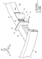
図1に示されるように、車体前部における車幅方向外側には、矩形閉断面形状とされて車体前後方向に延在するフロントサイドメンバ12が左右一対で配置されている。各フロントサイドメンバ12の前端部には、各フロントサイドメンバ12を閉塞するように矩形状の連結板14がそれぞれ設けられている。
As shown in FIG. 1, a pair of left and right
また、各連結板14には、それぞれ矩形状の連結板16が重ね合わされて接合されるようになっている。そして、各連結板16には、矩形閉断面形状とされたクラッシュボックス18が、それぞれ車体前方側へ向けて突設されている。つまり、各クラッシュボックス18は、連結板14、16を介して、平面視及び側面視で各フロントサイドメンバ12と同軸になるように設けられている。
In addition, a
更に、各クラッシュボックス18の車体前方側端部間には、矩形閉断面形状とされて車幅方向に延在するフロントバンパリインフォースメント20が架設されている。すなわち、各クラッシュボックス18の車体前方側端部は、それぞれフロントバンパリインフォースメント20の後面に接続されている。
Further, a
また、図2、図3に示されるように、左右のフロントサイドメンバ12間には、エンジン及びトランスミッション等を含むパワーユニット22が配設されている。そして、各フロントサイドメンバ12の車幅方向外側の壁部である外側壁12Aには、その外側壁12Aよりも車幅方向外側へ突出するように、平面視で車幅方向外側が頂点とされた略三角形状の突起部材30が締結固定されている。
As shown in FIGS. 2 and 3, a
図4に示されるように、突起部材30は、樹脂製部材(軟質部材)としての突起部材本体32と、その突起部材本体32を覆う金属製部材(硬質部材)としての(鉄板等の)カバー体34と、で構成されている。つまり、この突起部材30は、突起部材本体32及びカバー体34が平面視で車幅方向外側が頂点とされた略三角形状に形成されている。
As shown in FIG. 4, the protruding
なお、図5に示されるように、突起部材本体32の略中央部に略半球状の凹部33を形成し、突起部材本体32とフロントサイドメンバ12の外側壁12Aとの間に空隙部Sが形成されるようにしてもよい。
As shown in FIG. 5, a substantially hemispherical
また、図4、図5に示されるように、突起部材本体32の前端部及び後端部には、それぞれフランジ部32A、32Bが一体に形成されている。そして、カバー体34の前端部及び後端部にも、それぞれ各フランジ部32A、32Bに車幅方向外側から重ね合わされるフランジ部34A、34Bが一体に形成されている。
As shown in FIGS. 4 and 5,
更に、各フランジ部34A、32A及び各フランジ部34B、32Bには、それぞれボルト36を挿通させるための複数(例えば3個:図1参照)の貫通孔(図示省略)が形成されている。フランジ部34Aとフランジ部32Aに形成された各貫通孔は互いに連通しており、フランジ部34Bとフランジ部32Bに形成された各貫通孔も互いに連通している。
Further, a plurality of (for example, three: see FIG. 1) through-holes (not shown) through which the
そして、フロントサイドメンバ12の外側壁12Aには、各貫通孔と連通する複数の貫通孔(図示省略)が形成されており、その外側壁12Aの内面には、その複数の貫通孔と同軸的にウエルドナット37が設けられている。
A plurality of through holes (not shown) communicating with the respective through holes are formed in the
したがって、フランジ部34A、32A及びフランジ部34B、32Bに形成された各貫通孔に車幅方向外側からボルト36を挿通してウエルドナット37に螺合することにより、突起部材30が、フロントサイドメンバ12の外側壁12Aに締結固定される。なお、フランジ部34A、34Bの各貫通孔間には、平板状のリブ34C(図1参照)が一体に形成されており、カバー体34の剛性(強度)が向上されるようになっている。
Therefore, by inserting the
また、この突起部材本体32は、フランジ部32A、32Bを有しない構成とされていてもよい。つまり、カバー体34の内部に突起部材本体32を収容し、カバー体34のフランジ部34A、34Bのみをフロントサイドメンバ12の外側壁12Aに締結固定する構成にしてもよい。
Further, the protruding member
しかしながら、突起部材本体32にフランジ部32A、32Bを形成し、そのフランジ部32A、32Bをカバー体34のフランジ部34A、34Bと共にフロントサイドメンバ12の外側壁12Aに締結固定する方が望ましい。これによれば、カバー体34に対する突起部材本体32のがたつきが抑制又は防止される。
However, it is preferable to form
また、突起部材30の前端部(少なくともフランジ部34A)は、クラッシュボックス18よりも車体後方側でフロントサイドメンバ12の外側壁12Aに締結固定されている。そして、図2、図3に示されるように、突起部材30の後端部(少なくともフランジ部34B)は、平面視でパワーユニット22の車体前方側端部22Aよりも車体後方側で、かつパワーユニット22の車体前後方向中央部よりも車体前方側で、フロントサイドメンバ12の外側壁12Aに締結固定されている。
Further, the front end portion (at least the
なお、フロントサイドメンバ12の外側壁12Aに対する突起部材30の固定手段は、ボルト36及びウエルドナット37に限定されるものではない。例えば接着剤によって、各フランジ部34A、34Bを各フランジ部32A、32Bに接合するとともに、各フランジ部32A、32Bを外側壁12Aに接合して固定する構成にしてもよい。また、接着剤とボルト36及びウエルドナット37とを併用して突起部材30を外側壁12Aに固定する構成にしてもよい。
The means for fixing the protruding
また、図6に示されるように、パワーユニット22の右側の側部22Bの車体後方側(車体後方側における側部)には、荷重伝達部材としての直方体形状のスペーサー24が取り付けられている。このスペーサー24は、フロントサイドメンバ12の車幅方向内側の壁部である内側壁12Bと車幅方向で隙間を有する大きさに樹脂又は金属で形成されており、その隙間は、微小ラップ衝突時に、スペーサー24が内側壁12Bに当たることができる程度とされている。
As shown in FIG. 6, a
なお、このスペーサー24の前端部は、平面視で突起部材30の後端部(少なくともフランジ部34B)よりも車体後方側に配置されるようになっている。また、このスペーサー24は、パワーユニット22の側部22B(側部22C)の車体後方側に取り付けられる構成に限定されるものではない。
The front end portion of the
すなわち、パワーユニット22の側部22B(側部22C)の車体後方側と車幅方向で対向する、フロントサイドメンバ12の内側壁12Bの一部(所定位置)に取り付けられる構成とされてもよい。つまり、このスペーサー24は、フロントサイドメンバ12の内側壁12Bと、パワーユニット22の側部22B(側部22C)の車体後方側との間に介在するように設けられていればよい。
In other words, the
以上のような構成の車体前部構造10において、次にその作用について説明する。
Next, the operation of the vehicle
図2、図3に示されるように、例えば車両の左側のフロントサイドメンバ12よりも車幅方向外側、即ちフロントバンパリインフォースメント20の左端部20AがバリアWに衝突する微小ラップ衝突が発生すると、車両の前進に伴って、左側のフロントサイドメンバ12の外側壁12Aに突設された突起部材30がバリアWに衝突する。
As shown in FIGS. 2 and 3, for example, when a minute lap collision occurs in which the
ここで、この突起部材30の後端部(少なくともフランジ部34B)は、パワーユニット22の車体前方側端部22Aよりも車体後方側に位置している。そして、図4に示されるように、この突起部材30は、樹脂製の突起部材本体32が金属製のカバー体34で覆われることで構成されている。
Here, the rear end portion (at least the
すなわち、この突起部材30は、局所的な潰れが抑制される構成とされており、突起部材30による荷重伝達効率の低下が抑制されている。したがって、突起部材30がバリアWに衝突したときには、その衝突荷重の一部は、突起部材30からフロントサイドメンバ12を介してパワーユニット22へ効率よく伝達される(図3において矢印F1で示す)。
That is, the protruding
しかも、この突起部材30は、平面視で車幅方向外側を頂点とする略三角形状に形成されている。つまり、この突起部材30は、平面視で車幅方向に対して傾斜した傾斜面を有している。したがって、突起部材30がバリアWに衝突したときには、その傾斜面により、車幅方向(この場合は右側)へ向かう分力が効率よく得られる。よって、車両に対して横力(車幅方向で衝突側とは反対側へ向かう力)を効率よく発生させることができる。
In addition, the projecting
また、図6に示されるように、この場合の反衝突側である右側のフロントサイドメンバ12の内側壁12Bと、パワーユニット22の右側の側部22Bの車体後方側との間には、スペーサー24が介在されている。したがって、パワーユニット22に伝達された衝突荷重の一部は、そのスペーサー24を介して右側のフロントサイドメンバ12へ効率よく伝達される(図6において矢印F2で示す)。
Further, as shown in FIG. 6, a
つまり、このスペーサー24により、微小ラップ衝突によって発生した横力を反衝突側(この場合は右側)へ容易に伝達することができ、車両に対して横力を更に効率よく発生させることができる。よって、微小ラップ衝突時において、車室(乗員空間)をバリアWから遠ざけることができ、その車室(乗員空間)の変形を抑制又は防止することができる。
That is, the
また、図5に示されるように、突起部材本体32の略中央部に略半球状の凹部33が形成されていると、突起部材本体32とフロントサイドメンバ12の外側壁12Aとの間に空隙部Sを形成することができる。つまり、これによれば、フルラップ衝突時やオフセット衝突時において、フロントサイドメンバ12の軸圧縮変形の阻害を抑制することができ、フロントサイドメンバ12の軸圧縮変形によるエネルギー吸収効率の低下を抑制することができる。
Further, as shown in FIG. 5, when a substantially hemispherical
なお、連結板14と突起部材30の前端部(少なくともフランジ部34A)との間隔を広く取るようにすると、フルラップ衝突時やオフセット衝突時におけるフロントサイドメンバ12の軸圧縮変形の阻害をより一層抑制することができる。つまり、このような構成にすれば、フロントサイドメンバ12の軸圧縮変形によるエネルギー吸収効率の低下をより一層抑制することができる。
In addition, if the space | interval of the
また、突起部材30の前端部(少なくともフランジ部34A)は、クラッシュボックス18よりも車体後方側に位置しているので、フルラップ衝突時やオフセット衝突時において、突起部材30が、クラッシュボックス18によるエネルギー吸収を阻害することがない。つまり、フルラップ衝突時やオフセット衝突時に入力される衝突荷重は、その一部がクラッシュボックス18によって吸収される。
Further, since the front end portion (at least the
次に、本実施形態に係る車体前部構造10の変形例について説明する。
Next, a modified example of the vehicle
図7に示されるように、パワーユニット22の左側の側部22C(右側の側部22Bも同様)の車体前方側にスペーサー26を設ける構成にしてもよい。このスペーサー26も、スペーサー24と同様に、フロントサイドメンバ12の内側壁12Bと車幅方向で隙間を有する大きさに樹脂又は金属で形成されており、その隙間は、微小ラップ衝突時に、内側壁12Bがスペーサー26に当たることができる程度とされている。
As shown in FIG. 7, a
なお、図示のスペーサー26は、パワーユニット22の左側の側部22Cから車体前方側端部22Aへ跨って設けられているが、このスペーサー26は、少なくとも側部22C(側部22B)の車体前方側(車体前方側における側部)に設けられていればよい。また、このスペーサー26は、スペーサー24のときと同様に、パワーユニット22の側部22C(側部22B)の車体前方側と車幅方向で対向する、フロントサイドメンバ12の内側壁12Bの一部(所定位置)に設ける構成にしてもよい。
The illustrated
このようなスペーサー26を、フロントサイドメンバ12の内側壁12Bと、パワーユニット22の側部22C(側部22B)の車体前方側との間に介在させると、突起部材30がバリアWに衝突したときには、その突起部材30からフロントサイドメンバ12及びスペーサー26を介してパワーユニット22へ衝突荷重の一部が伝達される。つまり、これによれば、その衝突荷重の一部をパワーユニット22へ更に効率よく伝達することができ、微小ラップ衝突時に車両に対して発生させる横力を増加させることができる。
When such a
また、図8に示されるように、フロントサイドメンバ12の内部にバルクヘッド28を設ける構成にしてもよい。このバルクヘッド28は、車幅方向内側が開口した平面視略ハット型形状に形成されている。すなわち、このバルクヘッド28は、フロントサイドメンバ12の外側壁12Aの内面にスポット溶接によって接合される中板28Aを有している。
Further, as shown in FIG. 8, a configuration may be adopted in which a
そして、このバルクヘッド28は、中板28Aの前端部から車幅方向内側へ延在された前板28Bと、その前板28Bの車幅方向内側端部から車体前方側へ延在されたフランジ部28Cと、を有している。更に、このバルクヘッド28は、中板28Aの後端部から車幅方向内側へ延在された後板28Dと、その後板28Dの車幅方向内側端部から車体後方側へ延在されたフランジ部28Eと、を有している。
The
この前板28Bのフランジ部28Cと、後板28Dのフランジ部28Eとが、それぞれフロントサイドメンバ12の内側壁12Bの内面にスポット溶接によって接合されるようになっている。つまり、このバルクヘッド28は、フロントサイドメンバ12内において、外側壁12Aと内側壁12Bとを連結するようになっている。
The flange portion 28C of the
なお、中板28Aの外側壁12Aに対する接合手段及び各フランジ部28C、28Eの内側壁12Bに対する接合手段は、スポット溶接に限定されるものではない。また、このバルクヘッド28は、平面視で、フランジ部28C及び前板28Bが、突起部材30と車体前後方向でオーバーラップするような位置に設けられている。
In addition, the joining means with respect to the
このような位置にバルクヘッド28が設けられていると、突起部材30がバリアWに衝突したときには、その突起部材30からバルクヘッド28(フロントサイドメンバ12)を介してパワーユニット22へ衝突荷重の一部が伝達される。つまり、これによれば、その衝突荷重の一部をパワーユニット22へ更に効率よく伝達することができ、微小ラップ衝突時に車両に対して発生させる横力を増加させることができる。
When the
なお、スペーサー26とバルクヘッド28とを両方設ける構成にしてもよい。また、スペーサー26をフロントサイドメンバ12の内側壁12Bに設ける場合には、図8に示されるように、フランジ部34Bとバルクヘッド28(中板28A)とスペーサー26とを平面視で車幅方向に沿った一直線上に並べ、フランジ部34Bとスペーサー26とをボルト38及びナット39によって共締めするような構成にしてもよい。
Note that both the
つまり、この場合には、中板28Aにボルト38を挿通させるための貫通孔(図示省略)を形成し、内側壁12B及びスペーサー26にもボルト38を挿通させるための貫通孔(図示省略)を形成すればよい。また、この場合、図1に示されるフランジ部34B側のボルト36を全てボルト38に変更する必要はなく、例えば上下両端部のボルト36及びウエルドナット37をボルト38及びナット39に変更すればよい。
That is, in this case, a through hole (not shown) for inserting the
また、図9(A)に示されるように、突起部材30の車幅方向外側への突出長さを、図2に示されているものよりも長くし、平面視で突起部材30の車幅方向外側端部と前輪40の車幅方向内側端部とを車幅方向でオーバーラップさせるように構成してもよい(図9(A)において、オーバーラップさせている領域をHで示す)。
Further, as shown in FIG. 9A, the protruding length of the protruding
これによれば、図9(B)に示されるように、バリアWに対する車両の微小ラップ衝突により、そのバリアWに突起部材30が衝突すると、その突起部材30がバリアWによって相対的に車体後方側(矢印Gで示す)へ押される。すると、その突起部材30は、前輪40の車幅方向内側前端部に干渉し(車幅方向内側前端部を車体後方内側へ押圧し)、その前輪40を図示の矢印T方向へ回転させる(トーインさせる)。
According to this, as shown in FIG. 9B, when the protruding
つまり、これにより、前輪40を、その車体後方側に配置されたロッカ(図示省略)から離れる方向へ逃がすことができ、前輪40がロッカに干渉するのを抑制又は防止することができる。したがって、前輪40がロッカに干渉することによって生じる車室(乗員空間)の変形を抑制又は防止することができる。
In other words, this allows the
以上、本実施形態に係る車体前部構造10について、図面を基に説明したが、本実施形態に係る車体前部構造10は、図示のものに限定されるものではなく、本発明の要旨を逸脱しない範囲内において、適宜設計変更可能なものである。例えば図4に示されるように、樹脂製部材(突起部材本体32)とフロントサイドメンバ12の外側壁12Aとの間に空隙部Sが形成されていなくてもよい。
The vehicle
また、本実施形態に係る車体前部構造10では、フロントサイドメンバ12の軸圧縮変形の阻害を抑制する手段として空隙部Sを設けたが、その作用効果を奏する構成であれば、別の形態を採用するようにしてもよい。更に、本実施形態に係る車体前部構造10は、左右対称であるとして説明したが、左右対称でなくてもよい。
Further, in the vehicle
また、フロントサイドメンバ12の外側壁12Aに車幅方向外側へ突出する突起部材30が設けられ、その突起部材30の後端部(少なくともフランジ部34B)がパワーユニット22の車体前方側端部22Aよりも車体後方側に配置されていれば、所望とする作用効果が得られる。したがって、スペーサー24、26やバルクヘッド28などが設けられていなくてもよい。
Further, a protruding
また、突起部材30が設けられず、スペーサー24やスペーサー26だけが設けられる構成にしてもよい。更に、突起部材30は、樹脂製部材(突起部材本体32)と金属製部材(カバー体34)とで構成されるものに限定されるものではないし、その形状も、図示の平面視略三角形状に限定されるものではない。
Further, the
10 車体前部構造
12 フロントサイドメンバ
12A 外側壁
12B 内側壁
18 クラッシュボックス
22 パワーユニット
22A 車体前方側端部
22B 側部
24 スペーサー(荷重伝達部材)
30 突起部材
32 突起部材本体(樹脂製部材)
34 カバー体(金属製部材)
34B フランジ部(後端部)
S 空隙部
DESCRIPTION OF
30 Protruding
34 Cover body (metal member)
34B Flange (rear end)
S gap
Claims (6)
前記フロントサイドメンバの外側壁に、該外側壁よりも車幅方向外側へ突出するように、かつ平面視で前記フロントサイドメンバの車幅方向内側に配置されたパワーユニットの車体前方側端部よりも車体後方側に後端部が位置するように固定された突起部材と、
を備え、
前記突起部材は、
平面視で車幅方向外側後方へ傾斜した傾斜面とされた前面と、
前記フロントサイドメンバに固定される固定部に形成された平板状のリブと、
を有することを特徴とする車体前部構造。 A front side member disposed along the longitudinal direction of the vehicle body on the outer side in the vehicle width direction at the front of the vehicle body;
A vehicle body front side end portion of the power unit disposed on the outer side wall of the front side member so as to protrude outward in the vehicle width direction from the outer side wall and in the vehicle width direction inner side of the front side member in plan view. A protruding member fixed so that the rear end portion is located on the rear side of the vehicle body,
Equipped with a,
The protruding member is
A front surface that is inclined in the vehicle width direction rearward in plan view,
A plate-like rib formed on a fixed portion fixed to the front side member;
The vehicle body front part structure characterized by having .
Priority Applications (7)
| Application Number | Priority Date | Filing Date | Title |
|---|---|---|---|
| JP2012203000A JP5765310B2 (en) | 2012-09-14 | 2012-09-14 | Body front structure |
| EP13836457.5A EP2896551A4 (en) | 2012-09-14 | 2013-09-03 | FRONT STRUCTURE OF VEHICLE BODY |
| US14/426,861 US9290138B2 (en) | 2012-09-14 | 2013-09-03 | Vehicle front section structure |
| MX2015002949A MX358947B (en) | 2012-09-14 | 2013-09-03 | Vehicle body front structure. |
| BR112015005328A BR112015005328A2 (en) | 2012-09-14 | 2013-09-03 | vehicle front section structure |
| PCT/JP2013/073697 WO2014042041A1 (en) | 2012-09-14 | 2013-09-03 | Vehicle body front structure |
| CN201380046804.9A CN104619577B (en) | 2012-09-14 | 2013-09-03 | Vehicle body front structure |
Applications Claiming Priority (1)
| Application Number | Priority Date | Filing Date | Title |
|---|---|---|---|
| JP2012203000A JP5765310B2 (en) | 2012-09-14 | 2012-09-14 | Body front structure |
Publications (2)
| Publication Number | Publication Date |
|---|---|
| JP2014058184A JP2014058184A (en) | 2014-04-03 |
| JP5765310B2 true JP5765310B2 (en) | 2015-08-19 |
Family
ID=50278157
Family Applications (1)
| Application Number | Title | Priority Date | Filing Date |
|---|---|---|---|
| JP2012203000A Expired - Fee Related JP5765310B2 (en) | 2012-09-14 | 2012-09-14 | Body front structure |
Country Status (7)
| Country | Link |
|---|---|
| US (1) | US9290138B2 (en) |
| EP (1) | EP2896551A4 (en) |
| JP (1) | JP5765310B2 (en) |
| CN (1) | CN104619577B (en) |
| BR (1) | BR112015005328A2 (en) |
| MX (1) | MX358947B (en) |
| WO (1) | WO2014042041A1 (en) |
Families Citing this family (38)
| Publication number | Priority date | Publication date | Assignee | Title |
|---|---|---|---|---|
| US8789877B2 (en) | 2012-03-19 | 2014-07-29 | Honda Motor Co., Ltd. | Vehicle body front structure |
| JP5692191B2 (en) * | 2012-09-14 | 2015-04-01 | トヨタ自動車株式会社 | Body front structure |
| JP5692210B2 (en) | 2012-12-07 | 2015-04-01 | トヨタ自動車株式会社 | Body front structure |
| JP5888217B2 (en) * | 2012-12-07 | 2016-03-16 | トヨタ自動車株式会社 | Body front structure |
| JP5664637B2 (en) | 2012-12-07 | 2015-02-04 | トヨタ自動車株式会社 | Body front structure |
| JP5687723B2 (en) | 2013-02-15 | 2015-03-18 | トヨタ自動車株式会社 | Car body front structure and load receiving member |
| JP5895909B2 (en) * | 2013-09-04 | 2016-03-30 | トヨタ自動車株式会社 | Vehicle front structure |
| JP6020497B2 (en) * | 2014-03-24 | 2016-11-02 | トヨタ自動車株式会社 | Vehicle energy absorption structure and energy absorption member |
| US9421865B2 (en) * | 2014-04-04 | 2016-08-23 | Fca Italy S.P.A. | Motor vehicle provided with a powertrain unit and a safety device for moving the powertrain unit sideways during an impact |
| FR3019516B1 (en) * | 2014-04-04 | 2016-04-15 | Peugeot Citroen Automobiles Sa | MOTOR VEHICLE WITH CRASHBOX A BREAK PROGRAMMED IN CASE OF IMPACT FRONT. |
| US9715875B2 (en) | 2014-05-30 | 2017-07-25 | Apple Inc. | Reducing the need for manual start/end-pointing and trigger phrases |
| WO2015193972A1 (en) * | 2014-06-17 | 2015-12-23 | 日産ライトトラック株式会社 | Vehicle frame |
| KR102181519B1 (en) * | 2014-10-30 | 2020-11-24 | 사빅 글로벌 테크놀러지스 비.브이. | Intermittent side rail energy absorbing elements and methods of making the same |
| JP6139501B2 (en) | 2014-12-25 | 2017-05-31 | 本田技研工業株式会社 | Body front structure |
| JP6131967B2 (en) * | 2015-02-02 | 2017-05-24 | マツダ株式会社 | Auto body structure |
| JP6304078B2 (en) * | 2015-03-10 | 2018-04-04 | トヨタ自動車株式会社 | Vehicle front structure |
| JP6517558B2 (en) * | 2015-03-26 | 2019-05-22 | アイシン精機株式会社 | Bumper structure |
| US9815497B1 (en) | 2016-05-05 | 2017-11-14 | Toyota Motor Engineering & Manufacturing North America, Inc. | Vehicles including an engine compartment spacer member |
| US10189503B2 (en) | 2017-01-12 | 2019-01-29 | Nissan North America, Inc. | Vehicle body structure |
| US10118644B2 (en) * | 2017-01-12 | 2018-11-06 | Nissan North America, Inc. | Vehicle body structure |
| JP6544369B2 (en) * | 2017-03-03 | 2019-07-17 | マツダ株式会社 | Front body structure of the vehicle |
| EP3372455B1 (en) * | 2017-03-09 | 2020-07-01 | Volvo Car Corporation | Front bumper system for a vehicle |
| JP6855990B2 (en) | 2017-09-15 | 2021-04-07 | トヨタ自動車株式会社 | Vehicle front structure |
| EP3483040B1 (en) * | 2017-11-02 | 2020-11-25 | Toyota Jidosha Kabushiki Kaisha | Vehicle front portion structure |
| SE1751561A1 (en) * | 2017-12-18 | 2019-06-19 | Gestamp Hardtech Ab | Crash box for a bumper |
| US10661833B2 (en) | 2018-06-29 | 2020-05-26 | Nissan North America, Inc. | Vehicle body structure |
| KR102552507B1 (en) * | 2018-11-14 | 2023-07-06 | 현대자동차주식회사 | Vehicle front structure |
| DE102018129724B4 (en) * | 2018-11-26 | 2022-08-04 | Benteler Automobiltechnik Gmbh | Vehicle component for a vehicle |
| EP3666597B1 (en) * | 2018-12-12 | 2020-11-18 | C.R.F. Società Consortile per Azioni | Bumper beam with crash-box modules |
| DE102019104565B4 (en) * | 2019-02-22 | 2022-12-01 | Benteler Automobiltechnik Gmbh | Bumper assembly for a motor vehicle |
| CN111976834A (en) * | 2019-05-22 | 2020-11-24 | 上海汽车集团股份有限公司 | Vehicle and front longitudinal beam thereof |
| CN112009568B (en) * | 2019-05-30 | 2022-10-28 | 马自达汽车株式会社 | Powertrain support structure of vehicle |
| KR102687163B1 (en) | 2019-07-24 | 2024-07-19 | 현대자동차주식회사 | Front body structure of vehicle |
| US11254362B2 (en) | 2020-01-30 | 2022-02-22 | Toyota Motor Engineering & Manufacturing North America, Inc. | Vehicle rocker with load transferring spacer |
| US11407449B2 (en) | 2020-02-24 | 2022-08-09 | Nissan North America, Inc. | Energy absorbing structure for vehicle frame |
| US11511811B2 (en) | 2020-09-28 | 2022-11-29 | Nissan North America, Inc. | Vehicle front end assembly |
| US11511812B2 (en) | 2020-09-28 | 2022-11-29 | Nissan North America, Inc. | Vehicle front end assembly |
| US11845491B2 (en) * | 2021-05-05 | 2023-12-19 | Ford Global Technologies, Llc | Vehicle subframes and methods of producing the same |
Family Cites Families (27)
| Publication number | Priority date | Publication date | Assignee | Title |
|---|---|---|---|---|
| JPH07187003A (en) | 1993-12-27 | 1995-07-25 | Nissan Motor Co Ltd | Body front structure for automobile |
| JP2000053022A (en) | 1998-08-07 | 2000-02-22 | Honda Motor Co Ltd | Automobile body structure |
| JP2001270465A (en) | 2000-03-27 | 2001-10-02 | Fuji Heavy Ind Ltd | Body structure |
| JP3632666B2 (en) | 2002-02-01 | 2005-03-23 | 日産自動車株式会社 | Body front structure |
| JP4122887B2 (en) | 2002-08-05 | 2008-07-23 | 日産自動車株式会社 | Body front structure |
| DE102004036332B4 (en) * | 2004-07-27 | 2006-07-27 | Benteler Automobiltechnik Gmbh | Crash protection for frontal collision of vehicle has the respective front wheel turned inwards by impact sensor released servos to deflect some of the impact |
| JP2006103591A (en) * | 2004-10-07 | 2006-04-20 | Nissan Motor Co Ltd | Vehicle body front structure |
| JP2006175988A (en) * | 2004-12-22 | 2006-07-06 | Mazda Motor Corp | Vehicle front body structure |
| JP2006213093A (en) * | 2005-02-01 | 2006-08-17 | Toyota Motor Corp | Auto body front structure |
| JP4687138B2 (en) * | 2005-02-22 | 2011-05-25 | トヨタ自動車株式会社 | Vehicle front structure |
| JP4794985B2 (en) * | 2005-11-07 | 2011-10-19 | 富士重工業株式会社 | Vehicle frame structure |
| AT9043U1 (en) * | 2006-03-06 | 2007-04-15 | Magna Steyr Fahrzeugtechnik Ag | REJECTION DEVICE IN PART-COVERED FRONTAL COLLISION FOR MOTOR VEHICLES |
| CN101559786B (en) * | 2008-04-18 | 2010-12-29 | 北汽福田汽车股份有限公司 | Frontal and off-set collision energy absorption device and automobile with the same |
| JP5246139B2 (en) * | 2009-02-26 | 2013-07-24 | トヨタ自動車株式会社 | Vehicle front structure |
| WO2011049029A1 (en) * | 2009-10-19 | 2011-04-28 | 昭和電工株式会社 | Vehicle bumper beam and method for manufacturing same |
| JP5482180B2 (en) | 2009-12-17 | 2014-04-23 | トヨタ車体株式会社 | Car front bumper |
| JP5494229B2 (en) * | 2010-05-24 | 2014-05-14 | トヨタ自動車株式会社 | Pedestrian collision detection device |
| CN101982365A (en) * | 2010-10-21 | 2011-03-02 | 奇瑞汽车股份有限公司 | Bias collision device and automobile with same |
| DE102011004105A1 (en) * | 2011-02-15 | 2012-08-16 | Bayerische Motoren Werke Aktiengesellschaft | vehicle body |
| JP5817137B2 (en) * | 2011-02-16 | 2015-11-18 | マツダ株式会社 | Vehicle front structure |
| US20120241319A1 (en) | 2011-03-25 | 2012-09-27 | Life Safety Distribution Ag | Gas Detector Having Bipolar Counter/Reference Electrode |
| JP5357953B2 (en) * | 2011-04-01 | 2013-12-04 | 本田技研工業株式会社 | Body front structure |
| JP5544388B2 (en) * | 2012-03-29 | 2014-07-09 | 富士重工業株式会社 | Body front structure |
| JP5895701B2 (en) * | 2012-05-18 | 2016-03-30 | 日産自動車株式会社 | Body front structure |
| JP5880320B2 (en) * | 2012-07-06 | 2016-03-09 | トヨタ自動車株式会社 | Body front structure |
| US8807632B2 (en) * | 2012-10-02 | 2014-08-19 | Toyota Motor Engineering & Manufacturing North America, Inc. | Small overlap frontal impact countermeasure |
| US20140091585A1 (en) * | 2012-10-02 | 2014-04-03 | Toyota Motor Engineering & Manufacturing North America, Inc. | Small overlap frontal impact counter-measure |
-
2012
- 2012-09-14 JP JP2012203000A patent/JP5765310B2/en not_active Expired - Fee Related
-
2013
- 2013-09-03 US US14/426,861 patent/US9290138B2/en not_active Expired - Fee Related
- 2013-09-03 WO PCT/JP2013/073697 patent/WO2014042041A1/en active Application Filing
- 2013-09-03 EP EP13836457.5A patent/EP2896551A4/en not_active Withdrawn
- 2013-09-03 CN CN201380046804.9A patent/CN104619577B/en not_active Expired - Fee Related
- 2013-09-03 BR BR112015005328A patent/BR112015005328A2/en not_active Application Discontinuation
- 2013-09-03 MX MX2015002949A patent/MX358947B/en active IP Right Grant
Also Published As
| Publication number | Publication date |
|---|---|
| MX358947B (en) | 2018-09-07 |
| JP2014058184A (en) | 2014-04-03 |
| MX2015002949A (en) | 2015-06-02 |
| EP2896551A4 (en) | 2016-07-20 |
| EP2896551A1 (en) | 2015-07-22 |
| US20150246651A1 (en) | 2015-09-03 |
| WO2014042041A1 (en) | 2014-03-20 |
| CN104619577B (en) | 2016-12-14 |
| US9290138B2 (en) | 2016-03-22 |
| BR112015005328A2 (en) | 2017-07-04 |
| CN104619577A (en) | 2015-05-13 |
Similar Documents
| Publication | Publication Date | Title |
|---|---|---|
| JP5765310B2 (en) | Body front structure | |
| JP5692210B2 (en) | Body front structure | |
| JP6866784B2 (en) | Body undercarriage | |
| JP5664637B2 (en) | Body front structure | |
| US9517687B2 (en) | Battery unit mounting structure | |
| JP5812119B2 (en) | Lower body structure | |
| US9663147B2 (en) | Vehicle body front structure of a vehicle | |
| JP5835284B2 (en) | Body front structure | |
| JP6417668B2 (en) | Battery built-in structure | |
| JP5999134B2 (en) | Vehicle front structure | |
| JP5079061B2 (en) | Body front structure | |
| JP6137105B2 (en) | Battery drive battery mounting structure | |
| JP2019166873A (en) | Vehicle skeleton structure | |
| JP2017077762A (en) | Vehicle lower part structure | |
| CN111483420B (en) | Structure of vehicle | |
| JP2014162347A (en) | Vehicle front body structure | |
| JP2014125172A (en) | Vehicular front structure | |
| JP5803819B2 (en) | Vehicle front structure | |
| JP5831246B2 (en) | Body front structure | |
| JP5902636B2 (en) | Body front structure | |
| JP2011111036A (en) | Bumper device | |
| JP2013252775A (en) | Vehicle body lower part structure | |
| JP6597072B2 (en) | Vehicle front structure | |
| WO2010058467A1 (en) | Vehicle body structure and vehicle bumper | |
| JP6252080B2 (en) | Auto body front structure |
Legal Events
| Date | Code | Title | Description |
|---|---|---|---|
| A621 | Written request for application examination |
Free format text: JAPANESE INTERMEDIATE CODE: A621 Effective date: 20140227 |
|
| A131 | Notification of reasons for refusal |
Free format text: JAPANESE INTERMEDIATE CODE: A131 Effective date: 20150106 |
|
| A521 | Request for written amendment filed |
Free format text: JAPANESE INTERMEDIATE CODE: A523 Effective date: 20150304 |
|
| TRDD | Decision of grant or rejection written | ||
| A01 | Written decision to grant a patent or to grant a registration (utility model) |
Free format text: JAPANESE INTERMEDIATE CODE: A01 Effective date: 20150519 |
|
| A61 | First payment of annual fees (during grant procedure) |
Free format text: JAPANESE INTERMEDIATE CODE: A61 Effective date: 20150601 |
|
| R151 | Written notification of patent or utility model registration |
Ref document number: 5765310 Country of ref document: JP Free format text: JAPANESE INTERMEDIATE CODE: R151 |
|
| LAPS | Cancellation because of no payment of annual fees |