JP5740514B1 - Conductive bracket for solar cell module - Google Patents
Conductive bracket for solar cell module Download PDFInfo
- Publication number
- JP5740514B1 JP5740514B1 JP2014118278A JP2014118278A JP5740514B1 JP 5740514 B1 JP5740514 B1 JP 5740514B1 JP 2014118278 A JP2014118278 A JP 2014118278A JP 2014118278 A JP2014118278 A JP 2014118278A JP 5740514 B1 JP5740514 B1 JP 5740514B1
- Authority
- JP
- Japan
- Prior art keywords
- solar cell
- metal plate
- cell module
- gantry
- conductive
- Prior art date
- Legal status (The legal status is an assumption and is not a legal conclusion. Google has not performed a legal analysis and makes no representation as to the accuracy of the status listed.)
- Active
Links
Images


Classifications
-
- Y—GENERAL TAGGING OF NEW TECHNOLOGICAL DEVELOPMENTS; GENERAL TAGGING OF CROSS-SECTIONAL TECHNOLOGIES SPANNING OVER SEVERAL SECTIONS OF THE IPC; TECHNICAL SUBJECTS COVERED BY FORMER USPC CROSS-REFERENCE ART COLLECTIONS [XRACs] AND DIGESTS
- Y02—TECHNOLOGIES OR APPLICATIONS FOR MITIGATION OR ADAPTATION AGAINST CLIMATE CHANGE
- Y02B—CLIMATE CHANGE MITIGATION TECHNOLOGIES RELATED TO BUILDINGS, e.g. HOUSING, HOUSE APPLIANCES OR RELATED END-USER APPLICATIONS
- Y02B10/00—Integration of renewable energy sources in buildings
- Y02B10/10—Photovoltaic [PV]
-
- Y—GENERAL TAGGING OF NEW TECHNOLOGICAL DEVELOPMENTS; GENERAL TAGGING OF CROSS-SECTIONAL TECHNOLOGIES SPANNING OVER SEVERAL SECTIONS OF THE IPC; TECHNICAL SUBJECTS COVERED BY FORMER USPC CROSS-REFERENCE ART COLLECTIONS [XRACs] AND DIGESTS
- Y02—TECHNOLOGIES OR APPLICATIONS FOR MITIGATION OR ADAPTATION AGAINST CLIMATE CHANGE
- Y02E—REDUCTION OF GREENHOUSE GAS [GHG] EMISSIONS, RELATED TO ENERGY GENERATION, TRANSMISSION OR DISTRIBUTION
- Y02E10/00—Energy generation through renewable energy sources
- Y02E10/50—Photovoltaic [PV] energy
Landscapes
- Roof Covering Using Slabs Or Stiff Sheets (AREA)
Abstract
【課題】異種金属の導通金具の装着によって生じる異種金属接触腐食を抑制することができる太陽電池モジュール用導通金具を提供する。【解決手段】ステンレス材の表面にアルミ鍍金を施した金属板体1を設ける。隣接する太陽電池モジュールPを並べて支持する架台Qを設ける。架台Qの支持面Q1に金属板体1を載置するように構成する。金属板体1を切り起こして金属板体1の上面に複数の突起4を突設する。各フレームP1下面に該突起4が食い込むように設ける。隣接する太陽電池モジュールPの各フレームP1の下に金属板体1を敷いて電気的に接続する。【選択図】 図1Disclosed is a solar cell module conducting metal fitting capable of suppressing contact corrosion of different metals caused by mounting of a conducting metal fitting of a different metal. A metal plate 1 having an aluminum plating on the surface of a stainless steel material is provided. A gantry Q is provided to support adjacent solar cell modules P side by side. The metal plate 1 is configured to be placed on the support surface Q1 of the gantry Q. The metal plate 1 is cut and raised to project a plurality of protrusions 4 on the upper surface of the metal plate 1. The protrusions 4 are provided so as to bite into the lower surface of each frame P1. A metal plate 1 is placed under each frame P1 of the adjacent solar cell modules P to be electrically connected. [Selection] Figure 1
Description
本発明は、例えば屋根等に設置された複数の太陽電池モジュールの下に敷設するだけで太陽電池モジュール相互を電気的に接続することができる太陽電池モジュール用導通金具に関する。 The present invention relates to a solar cell module conducting metal fitting that can electrically connect solar cell modules to each other only by laying under a plurality of solar cell modules installed on, for example, a roof.
屋根等に載置された複数の太陽電池モジュールを相互に導通する場合、例えば特許文献1に記載のような太陽電池モジュール間の接続金具が使用されている。この接続金具は、鋭角な突起を有し、隣接する太陽電池モジュールのフレーム相互に係合する接続金具である。そして使用時に、太陽電池モジュールの端部フレームをボルトで架台に締付けると、鋭角な突起が両端部フレームの塗装を剥がして食い込み、これらを電気的に接続するように構成している。 When connecting a plurality of solar cell modules placed on a roof or the like to each other, for example, a connection fitting between solar cell modules as described in Patent Document 1 is used. This connection metal fitting is a connection metal fitting that has sharp protrusions and engages with the frames of adjacent solar cell modules. In use, when the end frame of the solar cell module is fastened to the pedestal with bolts, sharp projections peel off the paint on both end frames and electrically connect them.
一方、太陽電池モジュールの電気的接続を容易にするために、導電ワッシャーを使用した太陽電池モジュールの取付構造が特許文献2に記載されている。この取付構造では、太陽電池モジュールを架台に取り付けるボルトを導電ワッシャーに挿通し、ボルトを架台に取り付ける際に、この導電ワッシャーにて太陽電池モジュール相互を電気的に接続するものである。
On the other hand,
屋根等に太陽電池モジュールを載置する場合、太陽電池モジュールのフレームの材質に、軽量化と耐食性、耐候性を備えたアルミ押出材が広く使用されている。このアルミ材にて構成された太陽電池モジュールにアルミ材以外の材質の導通金具を使用すると電食あるいはガルバニック腐食と称する異種金属接触腐食が発生する虞がある。 When a solar cell module is placed on a roof or the like, an aluminum extruded material having light weight, corrosion resistance, and weather resistance is widely used as a material of a frame of the solar cell module. When a conductive metal fitting made of a material other than aluminum is used for a solar cell module made of this aluminum, there is a risk that dissimilar metal contact corrosion called electrolytic corrosion or galvanic corrosion may occur.
すなわち、従来の導通金具の材質は、導電性、強度、耐食性を備えたステンレス鋼やカラーステンレス鋼が広く使用されている。ところが、太陽電池モジュールの導通のため、アルミ製のフレーム相互間にステンレス製の導通金具を介在すると、電位の異なる金属材料が接触することになる。すなわち、金属の電位差によって、アルミ材が卑な金属の陽極(アノード)となり、ステンレス材が貴な金属の陰極(カソード)となって電流が流れ、陽極(アノード)がわのアルミ材のイオン化が助長されて腐食することになる。このような腐食が生じると、通電性が劣化し導通効果が低下するのみならず、太陽電池モジュールのフレーム強度にも悪影響を与えることになる。 That is, as the material of the conventional conducting metal fittings, stainless steel and color stainless steel having conductivity, strength, and corrosion resistance are widely used. However, for the conduction of the solar cell module, when a stainless steel metal fitting is interposed between the aluminum frames, metal materials having different potentials come into contact with each other. That is, due to the potential difference of the metal, the aluminum material becomes a base metal anode (anode), the stainless steel material becomes a noble metal cathode (cathode), current flows, and the anode (anode) ionizes the aluminum material. It is encouraged and corroded. When such corrosion occurs, not only the conductivity is deteriorated and the conduction effect is lowered, but also the frame strength of the solar cell module is adversely affected.
しかも、特許文献1及び特許文献2に記載の導通金具のように、従来の導通金具は、いずれも導通金具に開穿した孔にボルトを挿通する構造になっている。そのため、架台と太陽電池モジュールとの間に導通金具を装着するには、太陽電池モジュールをボルトで連結する前にこのボルトに導通金具を装着する必要があった。そのため、既に屋根等に装着されている太陽電池モジュールに後付で導通金具を装着する場合、連結ボルトから部材を取り外す必要が生じるなど、面倒な作業にならざるを得なかった。
Moreover, like the conductive metal fittings described in Patent Document 1 and
更に、特許文献1及び特許文献2に記載の導通金具は、いずれも太陽電池モジュールと架台の間に装着するので、装着後の導通金具は必然的に太陽電池モジュールにて隠れてしまう。したがって、工事完成後に、この導通金具が適正に装着されているか否かを目視で確認することができない状態になっており、導通金具の有無を確認するには、テスター等で導電性を計測するなど極めて面倒な作業が必要になっていた。
Furthermore, since the conducting metal fittings described in Patent Literature 1 and
そこで本発明は上述の課題を解消すべく創出されたもので、導通金具の装着によって太陽電池モジュールのフレームに生じる異種金属接触腐食を抑制することができ、しかも、装着作業が極めて簡単で後付の装着も容易になり、更に、太陽電池モジュール装着後でも導通金具の有無を目視で簡単に確認することができる太陽電池モジュール用導通金具の提供を目的とするものである。 Accordingly, the present invention has been created to solve the above-mentioned problems, and can prevent contact with different metals from occurring in the frame of the solar cell module due to the mounting of the conductive metal fittings. It is an object of the present invention to provide a conductive fitting for a solar cell module that can easily confirm the presence or absence of the conductive fitting visually even after the solar cell module is attached.
上述の目的を達成すべく本発明における第1の手段は、ステンレス材の表面にアルミ鍍金を施した金属板体1を設け、隣接する太陽電池モジュールPの各フレームP1下面を並べて支持する架台Qの支持面Q1に該金属板体1を載置するように構成し、金属板体1を切り起こして金属板体1の上面に複数の突起4を突設し、太陽電池モジュールPの各フレームP1下面に該突起4が食い込むように設け、隣接する太陽電池モジュールPの各フレームP1の下に金属板体1を敷設して太陽電池モジュールP相互を電気的に接続するように構成した太陽電池モジュール用導通金具において、
前記金属板体1は、前記突起4を備え前記架台Qの支持面Q1に載置する一対の導通片2と、各導通片2を連結する連結片3とで平面コ字形状を成し、前記架台Qの支持面Q1に載置した前記フレームP1の上部に係止する連結金具Sと前記架台Qとを連結する連結ボルトRの側面がわからスライドして前記架台Qの支持面Q1上に導通片2を載置するように構成している。
In order to achieve the above-mentioned object, the first means in the present invention includes a metal plate 1 having an aluminum plating on the surface of a stainless steel material, and a frame Q that supports the lower surfaces of the frames P1 of adjacent solar cell modules P side by side. The metal plate 1 is placed on the support surface Q1, and the metal plate 1 is cut and raised to project a plurality of
The metal plate 1 has a planar U-shape with a pair of
第2の手段は、前記架台Qの支持面Q1上に前記導通片2を載置したときに、前記架台Qの支持面Q1に載置した前記フレームP1間に前記連結片3が表出するように配置し、該連結片3にて前記金属板体1の装着状態を表示するように構成したものである。
The second means is that when the
第3の手段の前記突起4は、前記導通片2の下面から上面方向に貫通した先鋭状の突起物にて環状に突出する突起4が形成されたものである。
The
請求項1のように、ステンレス材の表面にアルミ鍍金を施した金属板体1を設け、隣接する太陽電池モジュールPの各フレームP1下面を並べて支持する架台Qの支持面Q1に該金属板体1を載置するように構成し、金属板体1を切り起こして金属板体1の上面に複数の突起4を突設し、太陽電池モジュールPの各フレームP1下面に該突起4が食い込むように設けたことにより、アルミ材のフレームP1にステンレス製の導通金具を装着しても異種金属接触腐食を抑制することができる。すなわち、突起4の先端の一部はステンレス材が表出し、このステンレス材の内側と外側はアルミ材にて被覆されている。そのため、突起4のステンレス材がフレームP1のアルミ材に食い込むと、ステンレス材の周囲がフレームP1のアルミ材と突起4を被覆するアルミ材とで包まれた状態になり、太陽電池モジュールP相互を導通しながらフレームP1の電食を抑制するものである。
As in claim 1, a metal plate 1 with aluminum plating on the surface of a stainless steel material is provided, and the metal plate on the support surface Q1 of the gantry Q that supports the bottom surfaces of the frames P1 of adjacent solar cell modules P side by side. 1 so that the metal plate 1 is cut and raised to project a plurality of
また、前記金属板体1は、前記突起4を備え前記架台Qの支持面Q1に載置する一対の導通片2と、各導通片2を連結する連結片3とで平面コ字形状を成し、前記フレームP1の上部に係止する連結金具Sと前記架台Qとを連結する連結ボルトRにて前記太陽電池モジュールPを固定する際に、該連結ボルトRの側面がわからスライドして前記架台Qの支持面Q1上に導通片2を載置するように構成したことで、金属板体1の装着作業を容易にすることができる。しかも、従来の導通金具のように連結ボルトRを通す必要がないので、仮に、太陽電池モジュールPを設置してから後付で金属板体1を装着する場合でも、連結ボルトRを緩めてフレームP1と架台Qとの間に隙間を開けるだけで簡単に装着することができる。
In addition , the metal plate 1 is formed in a plane U shape with a pair of
請求項2のように、前記架台Qの支持面Q1上に前記導通片2を載置したときに、前記架台Qの支持面Q1に載置した前記フレームP1間に前記連結片3が表出するように配置し、該連結片3にて前記金属板体1の装着状態を表示するように構成したことから、導通片2が太陽電池モジュールPに隠れていても隣接する太陽電池モジュールPの間で連結片3が表出するので、金属板体1の有無を一目で確認することができる。
As in
請求項3のごとく、前記突起4は、前記導通片2の下面から上面方向に貫通した先鋭状の突起物にて環状に突出する突起4が形成されたことから、環状突起4の先端は中央にステンレス材が表出し、環状突起4の内側と外側はアルミ材にて被覆されている。そのため、突起4中央のステンレス材がフレームP1のアルミ材に食い込むと、ステンレス材の周囲がフレームP1のアルミ材と突起4を被覆するアルミ材とで包まれた状態になる。ステンレス材の露出を極力小さくすることで電食抑制効果を期待することができる。
According to the third aspect of the present invention, since the
本発明によると、導通金具の装着によって太陽電池モジュールのフレームに生じる異種金属接触腐食を抑制することができ、しかも、装着作業が極めて簡単で後付の装着も容易になり、更に、太陽電池モジュール装着後でも導通金具の有無を目視で簡単に確認することができるなどといった当初の目的を達成した。 According to the present invention, the dissimilar metal contact corrosion generated in the frame of the solar cell module due to the mounting of the conductive metal fitting can be suppressed, the mounting operation is extremely simple, and the retrofitting can be easily performed. The initial objectives such as being able to easily confirm the presence or absence of the conductive metal fittings even after installation were achieved.
以下、本発明の実施例を説明する。本発明導通金具は、アルミ押出し材にて形成された太陽電池モジュールPのフレームP1相互間に介して、太陽電池モジュールP相互を電気的に接続する金具である(図2参照)。すなわち、隣接する太陽電池モジュールPの各フレームP1下面を並べて支持する架台Qの支持面Q1に載置して太陽電池モジュールPの下に敷設することで太陽電池モジュールP相互を電気的に接続するものである(図1参照)。 Examples of the present invention will be described below. The conducting metal fitting of the present invention is a metal fitting for electrically connecting the solar cell modules P to each other through the frames P1 of the solar cell modules P formed of an aluminum extruded material (see FIG. 2). That is, the solar cell modules P are electrically connected to each other by being placed on the support surface Q1 of the gantry Q that supports the side surfaces of the frames P1 of the adjacent solar cell modules P arranged side by side and laid under the solar cell module P. (See FIG. 1).
本発明導通金具は、ステンレス材の表面にアルミ鍍金を施した金属板体1にて構成される(図7参照)。そして、金属板体1を切り起こして各太陽電池モジュールPのフレームP1下面に食い込む複数の突起4を金属板体1の上面に突設している(図4、図5参照)。
The conducting metal fitting of the present invention is composed of a metal plate 1 in which the surface of a stainless steel is plated with aluminum (see FIG. 7). And the some
この突起4は、太陽電池モジュールPのフレームP1下面に食い込むことで、太陽電池モジュールP相互を電気的に接続するものである(図6参照)。すなわち、太陽電池モジュールPのフレームP1を構成しているアルミ材の特性として、アルミ材がステンレス材と接触すると異種金属接触腐食が発生し、この異種金属接触腐食が導電性の妨げになる。
The
そこで、ステンレス材の表面にアルミ鍍金を施した金属板体1を切り起こして突起4を形成すると、突起4先端のステンレス材が太陽電池モジュールPのフレームP1に食い込んで電気的に導通する。このとき、ステンレス材とフレームP1のアルミ材は接触するが、フレームP1に食い込んだステンレス材の周囲はフレームP1のアルミ材と金属板体1のアルミ鍍金とで包まれた状態になるので、ステンレス材とフレームP1のアルミ材の接触面積は小さく、電食による浸食が抑制されるものである。
Therefore, when the metal plate 1 with the aluminum plating applied to the surface of the stainless steel is cut and raised to form the
図示例の突起4は、金属板体1の下面側から上面方向に貫通する先鋭状の突起物にて環状に突出したものである(図4、図5参照)。この突起4によると、突起4の形成が容易で、しかも、フレームP1に食い込むステンレス材の面積が小さく、このステンレス材の周囲をアルミ材で包み込むことができる(図6参照)。
The
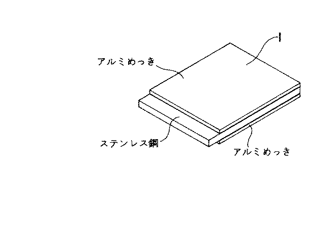
表1は、本発明導通金具の金属板体1と他の材質との腐食及び複合腐食サイクル試験(CCT試験)にて、試験前後の接続抵抗値の比較結果を示している。試験体は表欄上から順に「アルミめっきを施したステンレス(金属板体1)」、「カラーステンレス」、「SUS304(オーステナイト系ステンレス)」、「SUS430(フェライト系ステンレス)」とし、各材質それぞれ3体を試験体としたものである。試験方法は、図8に示すごとく、アルミ製の架台Qの支持面Q1に試験体を載せ、更に試験体の上に一対のアルミ押出材U(太陽電池モジュールのフレームを模している)を載置し、アルミ製の連結金具Sと連結ボルトRにてアルミ押出材Uを固定したものである。
*接続抵抗値はアルミ押出材U相互間を測定した。
*接続抵抗は試験前とCCT試験終了後(100サイクル)に測定する。
*連結ボルトRの締付けトルクは14.7N・mとした。
Table 1 shows the comparison results of the connection resistance values before and after the test in the corrosion and composite corrosion cycle test (CCT test) between the metal plate 1 of the conductive metal fitting of the present invention and other materials. The test specimens are “stainless steel with aluminum plating (metal plate 1)”, “color stainless steel”, “SUS304 (austenitic stainless steel)” and “SUS430 (ferritic stainless steel)” in order from the top of the table. Three specimens were used as test specimens. As shown in FIG. 8, the test method is such that a test body is placed on the support surface Q1 of the aluminum gantry Q, and a pair of aluminum extrusions U (simulating the frame of the solar cell module) is further placed on the test body. The aluminum extruded member U is fixed by an aluminum connecting fitting S and a connecting bolt R.
* The connection resistance value was measured between aluminum extruded materials U.
* Connection resistance is measured before the test and after the end of the CCT test (100 cycles).
* The tightening torque of the connecting bolt R was 14.7 N · m.
試験の結果、試験前後において、「アルミめっきを施したステンレス」が最も抵抗値が低かった。「カラーステンレス」は試験前後の抵抗値に大きな差はないが、「アルミめっきを施したステンレス」より抵抗値が大きく、試験体によって導通状態が不安定であった。
「SUS304」、「SUS430」は、「アルミめっきを施したステンレス」及び「カラーステンレス」に比べると、試験後の抵抗値上昇が大きいことがわかる。特に、極端に抵抗値が上昇している試験体は、アルミ押出材Uが腐食したものと考えられる。
以上の結果より、4種類の材質の中で「アルミめっきを施したステンレス」が導通金具として最も適した材質であるといえる。
As a result of the test, before and after the test, “aluminum-plated stainless steel” had the lowest resistance value. “Color stainless steel” had no significant difference in resistance before and after the test, but the resistance value was larger than “aluminum-plated stainless steel” and the conduction state was unstable depending on the specimen.
It can be seen that “SUS304” and “SUS430” have a large increase in resistance after the test compared to “stainless steel plated with aluminum” and “colored stainless steel”. In particular, it is considered that the test specimen whose resistance value is extremely increased is that the aluminum extruded material U is corroded.
From the above results, it can be said that “aluminum-plated stainless steel” is the most suitable material for the conductive metal fitting among the four types of materials.
金属板体1は、一対の導通片2と、各導通片2を連結する連結片3とで平面コ字形状を成している(図4参照)。各導通片2は上面に突起4を備え、架台Qの各支持面Q1に載置する。そして、フレームP1の上部に係止する連結金具Sと架台Qとを連結する連結ボルトRにて太陽電池モジュールPを固定する際に、該連結ボルトRの側面がわから金属板体1をスライドして架台Qの支持面Q1上に導通片2を載置するものである(図3参照)。
The metal plate 1 is formed in a plane U shape by a pair of
図示の架台Qは、ハゼ式折板屋根のハゼ部に固定する固定金具Tと、該固定金具Tに立設された連結ボルトRに貫通する架台Qと、太陽電池モジュールPのフレームP1の上部に係止し連結ボルトRを挿通する連結金具Sとで構成している(図1参照)。そして、架台Qの支持面Q1上に太陽電池モジュールPのフレームP1を載置し、該フレームP1の上部を連結金具Sが係止し、連結ボルトRで固定するものである。このような架台Qに対して金属板体1を支持面Q1に載置してフレームP1の下に敷くものである(図2参照)。また、金属板体1の載置位置はこの例に限らず、例えば、フレームP1の上部に金属板体1を載置し、この金属板体1の上から連結金具SでフレームP1の上部を固定するといった使用も可能である。尚、架台Qも図示例に限らずフレームP1を載置するものであれば形状や構造は問わない。 The illustrated gantry Q includes a fixing bracket T that is fixed to the seam portion of the goby-type folded plate roof, a gantry Q that penetrates a connecting bolt R that is erected on the fixing bracket T, and an upper portion of the frame P1 of the solar cell module P. And a connecting metal fitting S that is inserted through the connecting bolt R (see FIG. 1). Then, the frame P1 of the solar cell module P is placed on the support surface Q1 of the gantry Q, and the upper part of the frame P1 is locked by the connection fitting S and fixed by the connection bolt R. The metal plate 1 is placed on the support surface Q1 with respect to the gantry Q and laid under the frame P1 (see FIG. 2). Moreover, the mounting position of the metal plate 1 is not limited to this example. For example, the metal plate 1 is placed on the upper part of the frame P1, and the upper part of the frame P1 is connected to the upper part of the metal plate 1 with the connecting metal S. It can also be used for fixing. The gantry Q is not limited to the illustrated example, and any shape or structure may be used as long as the frame P1 is placed thereon.
図示の導通片2は、各導通片2の長手端部を下に屈曲して係止部5を設けている(図5参照)。そして、この係止部5を架台Qの支持面Q1端部に係止すると、支持面Q1上に載置した金属板体1の配置位置が適正な位置になると共に、突起4の向きが上向きになるように構成している。
The illustrated
更に、平面コ字形状の金属板体1を架台Qの支持面Q1に載置すると、架台Qの支持面Q1に載置したフレームP1間に連結片3が表出することになる(図2参照)。したがって、この連結片3にて金属板体1の装着状態を表示できるので、太陽電池モジュールP設置後でも、導通金具の確認を目視で行えるものである。図示の連結片3には、目視用の目印として半円形状の表示部3Aを形成している。この表示部3Aは、この他、連結片3に着色を施して表示部3Aとすることも可能である。
Furthermore, when the planar U-shaped metal plate 1 is placed on the support surface Q1 of the gantry Q, the connecting
尚、本発明の金属板体1の各構成は図示例に限定されるものではなく、導通片2や連結片3、突起4等の形状は本発明の要旨を変更しない範囲で自由に設計変更することができる。
In addition, each structure of the metal plate 1 of this invention is not limited to the example of illustration, The shape of the conduction |
P 太陽電池モジュール
Q 架台
Q1 支持面
R 連結ボルト
S 連結金具
T 固定金具
U アルミ押出材
1 金属板体
2 導通片
3 連結片
3A 表示部
4 突起
5 係止部
P solar cell module Q mount Q1 support surface R connecting bolt S connecting bracket T fixing bracket U aluminum extruded material 1
Claims (3)
前記金属板体は、前記突起を備え前記架台の支持面に載置する一対の導通片と、各導通片を連結する連結片とで平面コ字形状を成し、前記フレームの上部に係止する連結金具と前記架台とを連結する連結ボルトにて前記太陽電池モジュールを固定する際に、該連結ボルトの側面がわからスライドして前記架台の支持面上に導通片を載置するように構成したことを特徴とする太陽電池モジュール用導通金具。 A metal plate body provided with an aluminum plating on the surface of a stainless steel material, and configured so that the metal plate body is placed on a support surface of a gantry that supports the lower surface of each frame of adjacent solar cell modules side by side. Is cut and raised to project a plurality of protrusions on the upper surface of the metal plate body, so that the protrusions bite into the lower surface of each frame of the solar cell module, and a metal plate body is laid under each frame of the adjacent solar cell module In the solar cell module conductive metal fitting configured to electrically connect the solar cell modules to each other,
The metal plate body is formed in a planar U shape with a pair of conductive pieces provided on the support surface of the gantry and provided with the protrusions, and a connecting piece for connecting the conductive pieces, and is locked to the upper portion of the frame. When fixing the solar cell module with a connecting bolt that connects the connecting metal fitting and the gantry, the side surface of the connecting bolt slides from the side and the conductive piece is placed on the support surface of the gantry solar cell module conductive metal, characterized in that the.
Priority Applications (1)
| Application Number | Priority Date | Filing Date | Title |
|---|---|---|---|
| JP2014118278A JP5740514B1 (en) | 2014-06-09 | 2014-06-09 | Conductive bracket for solar cell module |
Applications Claiming Priority (1)
| Application Number | Priority Date | Filing Date | Title |
|---|---|---|---|
| JP2014118278A JP5740514B1 (en) | 2014-06-09 | 2014-06-09 | Conductive bracket for solar cell module |
Publications (2)
| Publication Number | Publication Date |
|---|---|
| JP5740514B1 true JP5740514B1 (en) | 2015-06-24 |
| JP2015229912A JP2015229912A (en) | 2015-12-21 |
Family
ID=53534150
Family Applications (1)
| Application Number | Title | Priority Date | Filing Date |
|---|---|---|---|
| JP2014118278A Active JP5740514B1 (en) | 2014-06-09 | 2014-06-09 | Conductive bracket for solar cell module |
Country Status (1)
| Country | Link |
|---|---|
| JP (1) | JP5740514B1 (en) |
Cited By (1)
| Publication number | Priority date | Publication date | Assignee | Title |
|---|---|---|---|---|
| JP2020101036A (en) * | 2018-12-25 | 2020-07-02 | 株式会社サカタ製作所 | Mounting tool and manufacturing method thereof |
Families Citing this family (4)
| Publication number | Priority date | Publication date | Assignee | Title |
|---|---|---|---|---|
| EP3467941A1 (en) * | 2016-05-30 | 2019-04-10 | AAAG Seros Training, S.L. | Galvanic isolation and electrical connection element for photovoltaic installations and photovoltaic installation comprising said element |
| JP2018102045A (en) * | 2016-12-20 | 2018-06-28 | 株式会社動力 | Solar cell module fixing structure and earth plate used therefor |
| JP7397607B2 (en) * | 2019-09-18 | 2023-12-13 | 積水化学工業株式会社 | PF tube fixing saddle and wiring structure |
| KR102350826B1 (en) * | 2021-08-02 | 2022-01-14 | 주식회사 바인딩 | Solar power generation system installed outside the building |
Citations (7)
| Publication number | Priority date | Publication date | Assignee | Title |
|---|---|---|---|---|
| JP2002252364A (en) * | 2001-02-26 | 2002-09-06 | Canon Inc | Solar cell module array and method of installing solar cell module |
| JP2010261257A (en) * | 2009-05-11 | 2010-11-18 | Yane Gijutsu Kenkyusho:Kk | Solar cell module fixing structure |
| JP4856279B1 (en) * | 2011-05-30 | 2012-01-18 | マジカナテック株式会社 | Roof panel fittings |
| JP2012149402A (en) * | 2011-01-18 | 2012-08-09 | Lixil Energy Co Ltd | Grounding structure of solar energy utilization device and frame crosspiece member having conductive function |
| JP2013087579A (en) * | 2011-10-21 | 2013-05-13 | Daidohant Co Ltd | Fixture device for solar cell module installation apparatus |
| JP2013209819A (en) * | 2012-03-30 | 2013-10-10 | Nisshin Steel Co Ltd | Method for installing photovoltaic module in architectural structure |
| WO2014016882A1 (en) * | 2012-07-23 | 2014-01-30 | 株式会社屋根技術研究所 | Securing structure for solar cell module |
-
2014
- 2014-06-09 JP JP2014118278A patent/JP5740514B1/en active Active
Patent Citations (7)
| Publication number | Priority date | Publication date | Assignee | Title |
|---|---|---|---|---|
| JP2002252364A (en) * | 2001-02-26 | 2002-09-06 | Canon Inc | Solar cell module array and method of installing solar cell module |
| JP2010261257A (en) * | 2009-05-11 | 2010-11-18 | Yane Gijutsu Kenkyusho:Kk | Solar cell module fixing structure |
| JP2012149402A (en) * | 2011-01-18 | 2012-08-09 | Lixil Energy Co Ltd | Grounding structure of solar energy utilization device and frame crosspiece member having conductive function |
| JP4856279B1 (en) * | 2011-05-30 | 2012-01-18 | マジカナテック株式会社 | Roof panel fittings |
| JP2013087579A (en) * | 2011-10-21 | 2013-05-13 | Daidohant Co Ltd | Fixture device for solar cell module installation apparatus |
| JP2013209819A (en) * | 2012-03-30 | 2013-10-10 | Nisshin Steel Co Ltd | Method for installing photovoltaic module in architectural structure |
| WO2014016882A1 (en) * | 2012-07-23 | 2014-01-30 | 株式会社屋根技術研究所 | Securing structure for solar cell module |
Cited By (2)
| Publication number | Priority date | Publication date | Assignee | Title |
|---|---|---|---|---|
| JP2020101036A (en) * | 2018-12-25 | 2020-07-02 | 株式会社サカタ製作所 | Mounting tool and manufacturing method thereof |
| JP7002755B2 (en) | 2018-12-25 | 2022-01-20 | 株式会社サカタ製作所 | Mounting equipment and its manufacturing method |
Also Published As
| Publication number | Publication date |
|---|---|
| JP2015229912A (en) | 2015-12-21 |
Similar Documents
| Publication | Publication Date | Title |
|---|---|---|
| JP6033922B1 (en) | Conductive plate for solar cell module | |
| JP5740514B1 (en) | Conductive bracket for solar cell module | |
| JP4679409B2 (en) | Grounding structure and grounding fixture for solar cell module | |
| JPWO2014016882A1 (en) | Solar cell module fixing structure | |
| Charles-Granville et al. | Application of finite element modeling to macro-galvanic coupling of AA7050 and SS316: validation using the scanning vibrating electrode technique | |
| EA200702065A1 (en) | ANODE SUPPORTING DEVICE | |
| US20120255597A1 (en) | Electrical Conductor Arrangement as a Component of a Photovoltaic Array | |
| US6328860B1 (en) | Diaphragm cell cathode busbar structure | |
| US4264426A (en) | Electrolytic cell and a method for manufacturing the same | |
| US3366567A (en) | Electroplating rack | |
| JP6025770B2 (en) | Fixing bracket for solar cell module and fixing structure for solar cell module | |
| CN209537638U (en) | A kind of sacrificial anode device | |
| JP2019047640A (en) | Cable support | |
| CN105932616A (en) | Leakage warning cable clamp | |
| JP2010150634A (en) | Crossbar for electrode plate and the electrode plate | |
| CN205812549U (en) | Electronic housing backboard and the attachment structure of connector | |
| CN202957353U (en) | Zinc-coated copper covered steel anode anticorrosion lightning protection and antistatic instrument and electrical ground system | |
| CN101750440B (en) | Method for detecting assembly quality of cathode carbon block of electrolytic cell and test fixture | |
| CN109283366B (en) | Wire rod test fixture | |
| JP2007211434A (en) | Solar cell panel mounting base | |
| JPS5818814Y2 (en) | Denki Yuwakashiki | |
| CN223575934U (en) | Display screen mounting assembly | |
| CN216514145U (en) | Sacrificial anode block for corrosion prevention of tower foot of power transmission angle steel tower | |
| JP2012026153A (en) | Assembly structure of case element of lock case and tumbler receiving seat | |
| CN105929204A (en) | Thyristor test device and handle thereof for thyristor test |
Legal Events
| Date | Code | Title | Description |
|---|---|---|---|
| A521 | Request for written amendment filed |
Free format text: JAPANESE INTERMEDIATE CODE: A523 Effective date: 20150326 |
|
| TRDD | Decision of grant or rejection written | ||
| A01 | Written decision to grant a patent or to grant a registration (utility model) |
Free format text: JAPANESE INTERMEDIATE CODE: A01 Effective date: 20150414 |
|
| A61 | First payment of annual fees (during grant procedure) |
Free format text: JAPANESE INTERMEDIATE CODE: A61 Effective date: 20150427 |
|
| R150 | Certificate of patent or registration of utility model |
Ref document number: 5740514 Country of ref document: JP Free format text: JAPANESE INTERMEDIATE CODE: R150 |
|
| R250 | Receipt of annual fees |
Free format text: JAPANESE INTERMEDIATE CODE: R250 |
|
| R250 | Receipt of annual fees |
Free format text: JAPANESE INTERMEDIATE CODE: R250 |
|
| R250 | Receipt of annual fees |
Free format text: JAPANESE INTERMEDIATE CODE: R250 |
|
| R250 | Receipt of annual fees |
Free format text: JAPANESE INTERMEDIATE CODE: R250 |
|
| R250 | Receipt of annual fees |
Free format text: JAPANESE INTERMEDIATE CODE: R250 |
|
| R250 | Receipt of annual fees |
Free format text: JAPANESE INTERMEDIATE CODE: R250 |
|
| R250 | Receipt of annual fees |
Free format text: JAPANESE INTERMEDIATE CODE: R250 |
|
| R250 | Receipt of annual fees |
Free format text: JAPANESE INTERMEDIATE CODE: R250 |