JP5731099B2 - Combination grip for exercise equipment - Google Patents
Combination grip for exercise equipment Download PDFInfo
- Publication number
- JP5731099B2 JP5731099B2 JP2008539168A JP2008539168A JP5731099B2 JP 5731099 B2 JP5731099 B2 JP 5731099B2 JP 2008539168 A JP2008539168 A JP 2008539168A JP 2008539168 A JP2008539168 A JP 2008539168A JP 5731099 B2 JP5731099 B2 JP 5731099B2
- Authority
- JP
- Japan
- Prior art keywords
- loop
- hand grip
- attached
- grip
- strap
- Prior art date
- Legal status (The legal status is an assumption and is not a legal conclusion. Google has not performed a legal analysis and makes no representation as to the accuracy of the status listed.)
- Active
Links
- 210000003811 finger Anatomy 0.000 description 50
- 210000002683 foot Anatomy 0.000 description 27
- 230000033001 locomotion Effects 0.000 description 26
- 239000000463 material Substances 0.000 description 17
- 230000007246 mechanism Effects 0.000 description 12
- 210000002414 leg Anatomy 0.000 description 9
- 239000000835 fiber Substances 0.000 description 8
- 210000003205 muscle Anatomy 0.000 description 6
- 230000036544 posture Effects 0.000 description 6
- 230000036961 partial effect Effects 0.000 description 5
- 210000003371 toe Anatomy 0.000 description 5
- 239000004677 Nylon Substances 0.000 description 4
- 239000004743 Polypropylene Substances 0.000 description 4
- 210000004247 hand Anatomy 0.000 description 4
- 229920001778 nylon Polymers 0.000 description 4
- -1 polypropylene Polymers 0.000 description 4
- 229920001155 polypropylene Polymers 0.000 description 4
- 230000008859 change Effects 0.000 description 3
- 239000002184 metal Substances 0.000 description 3
- 239000004033 plastic Substances 0.000 description 3
- 229920003023 plastic Polymers 0.000 description 3
- 230000009471 action Effects 0.000 description 2
- 239000000853 adhesive Substances 0.000 description 2
- 230000001070 adhesive effect Effects 0.000 description 2
- 230000006872 improvement Effects 0.000 description 2
- 210000003127 knee Anatomy 0.000 description 2
- 238000012986 modification Methods 0.000 description 2
- 230000004048 modification Effects 0.000 description 2
- 229920001084 poly(chloroprene) Polymers 0.000 description 2
- 230000002441 reversible effect Effects 0.000 description 2
- 238000004904 shortening Methods 0.000 description 2
- 229920000742 Cotton Polymers 0.000 description 1
- 240000008168 Ficus benjamina Species 0.000 description 1
- 210000001015 abdomen Anatomy 0.000 description 1
- 238000004873 anchoring Methods 0.000 description 1
- 210000000617 arm Anatomy 0.000 description 1
- 238000005452 bending Methods 0.000 description 1
- 238000006243 chemical reaction Methods 0.000 description 1
- 230000007423 decrease Effects 0.000 description 1
- 230000003247 decreasing effect Effects 0.000 description 1
- 238000010586 diagram Methods 0.000 description 1
- 238000006073 displacement reaction Methods 0.000 description 1
- 229920001971 elastomer Polymers 0.000 description 1
- 210000000474 heel Anatomy 0.000 description 1
- 239000004619 high density foam Substances 0.000 description 1
- 238000009434 installation Methods 0.000 description 1
- 239000003562 lightweight material Substances 0.000 description 1
- 230000000670 limiting effect Effects 0.000 description 1
- 210000003739 neck Anatomy 0.000 description 1
- 229920005594 polymer fiber Polymers 0.000 description 1
- 239000007779 soft material Substances 0.000 description 1
- 230000003068 static effect Effects 0.000 description 1
- 230000009182 swimming Effects 0.000 description 1
- 210000003813 thumb Anatomy 0.000 description 1
Images


Classifications
-
- A—HUMAN NECESSITIES
- A63—SPORTS; GAMES; AMUSEMENTS
- A63B—APPARATUS FOR PHYSICAL TRAINING, GYMNASTICS, SWIMMING, CLIMBING, OR FENCING; BALL GAMES; TRAINING EQUIPMENT
- A63B21/00—Exercising apparatus for developing or strengthening the muscles or joints of the body by working against a counterforce, with or without measuring devices
- A63B21/02—Exercising apparatus for developing or strengthening the muscles or joints of the body by working against a counterforce, with or without measuring devices using resilient force-resisters
- A63B21/055—Exercising apparatus for developing or strengthening the muscles or joints of the body by working against a counterforce, with or without measuring devices using resilient force-resisters extension element type
- A63B21/0552—Elastic ropes or bands
-
- A—HUMAN NECESSITIES
- A63—SPORTS; GAMES; AMUSEMENTS
- A63B—APPARATUS FOR PHYSICAL TRAINING, GYMNASTICS, SWIMMING, CLIMBING, OR FENCING; BALL GAMES; TRAINING EQUIPMENT
- A63B21/00—Exercising apparatus for developing or strengthening the muscles or joints of the body by working against a counterforce, with or without measuring devices
- A63B21/15—Arrangements for force transmissions
- A63B21/151—Using flexible elements for reciprocating movements, e.g. ropes or chains
Landscapes
- Health & Medical Sciences (AREA)
- Life Sciences & Earth Sciences (AREA)
- Biophysics (AREA)
- Orthopedic Medicine & Surgery (AREA)
- General Health & Medical Sciences (AREA)
- Physical Education & Sports Medicine (AREA)
- Rehabilitation Tools (AREA)
- Walking Sticks, Umbrellas, And Fans (AREA)
- Orthopedics, Nursing, And Contraception (AREA)
Description
ここに開示されているいくつかの実施例は、運動器具に関し、特に、様々な運動に用いるために簡単に製造可能な非弾性ストラップを具える運動器具用グリップに関する。 Some embodiments disclosed herein relate to exercise equipment, and in particular to exercise equipment grips that include an inelastic strap that can be easily manufactured for use in a variety of exercises.
抵抗運動器具は、ユーザの腕、足、又は胴の動きに抵抗を与えることによって、ユーザが運動を行うようにする。ここに使われる用語「抵抗運動器具」は、ある筋肉が別の筋肉に作用することによって、又はユーザの重量に作用することによって抵抗を与える部分の運動器具を意味し、抵抗力を増すために弾性バンドを具えうる。さらに具体的には、ここに使用される抵抗運動器具は、ユーザが運動するのに対し、大きな又は付加的な重量を具えていない。これらの器具の有用性の一部は、器具を用いてユーザが行うことができる、運動の種類、運動の範囲や数の容易さ、及び様々なユーザがこれらの身長、体重、力、および/または身体的な制限に合わせて器具を調節できるという容易さによる。さらに、抵抗運動器具は、しばしば、軽量で、持ち運び可能にしうる。 Resistance exercise equipment allows a user to exercise by imparting resistance to the movement of the user's arms, legs or torso. As used herein, the term "resistance exercise equipment" refers to a portion of exercise equipment that provides resistance by acting on one muscle to another muscle or acting on the weight of the user to increase resistance. An elastic band may be provided. More specifically, the resistance exercise equipment used herein does not have a large or additional weight for the user to exercise. Some of the usefulness of these devices is that the types of exercises, the range and number of exercises that can be performed by the user with the devices, and the various users' height, weight, strength, and / or Or because of the ease with which the instrument can be adjusted to meet physical limitations. In addition, resistance exercise equipment can often be lightweight and portable.
弾性バンドを具える抵抗運動器具は、通常、ユーザの腕および/または足の動き、又はユーザと支持構造の間の動きを制限する。弾性運動器具は、小さく、さらには、持ち運び可能にできるが、弾性バンドの長さ及び弾性によるこれらの抵抗特性の有用性を制限してしまう。これらの特徴から、弾性バンドは、特定の長さ範囲で有用であり、これにより、これを使用する運動の多様性を制限してしまう。さらに、異なるユーザ間では、身長や体重、力が異なるので、ユーザが異なると、同じ器具を同じ運動に使うことはできないという潜在性がある。このように、弾性器具は、完全なトレーニングを提供する又は、異なるユーザ間で使用できる等、一般的に有用であるように、複数の弾性バンドは、簡単に相互で交換可能である必要がある。多様な運動を通じて一般的に有用性が必要とされて、簡単に用いることができる器具は、従来技術では未だ知られていない。 Resistance exercise equipment with elastic bands typically limit the movement of the user's arms and / or legs, or the movement between the user and the support structure. Elastic exercise equipment can be small and even portable, but limits the usefulness of these resistance characteristics due to the length and elasticity of the elastic band. Because of these features, elastic bands are useful in certain length ranges, thereby limiting the variety of motions that use them. Furthermore, since different users have different heights, weights, and strengths, there is a potential that different users cannot use the same equipment for the same exercise. Thus, multiple elastic bands need to be easily interchangeable so that the elastic device is generally useful, such as providing complete training or being usable between different users. . Devices that are generally useful through a variety of exercises and are easy to use are not yet known in the prior art.
弾性抵抗運動器具の別の制限は、抵抗に一貫性が無く、変位が大きくなるに伴って増加して、ユーザが作用力を減少させると、急に元に戻ってしまう傾向があるという事である。この抵抗反応によって、小型設計にできるが、ランニング、水泳など、普通の種類の運動の間に、筋肉によって与えられる抵抗を再現しえないという問題がある。しかし、弾性器具の別の制限は、ユーザの幅広い重量を支持できないということであり、通常、器具は、ユーザの筋肉による抵抗のみを支持するように構成されている。これは、様々な個々の弾性器具を用いて行う運動に極端な制限を作り出す。このため、さらには、弾性器具は、姿勢の限度範囲、さらにはユーザのトレーニングの限度を超えて使用される必要がある。 Another limitation of elastic resistance exercise equipment is that the resistance is inconsistent and increases with increasing displacement and tends to return suddenly if the user decreases the applied force. is there. This resistance reaction allows a compact design, but there is a problem that the resistance imparted by the muscles cannot be reproduced during normal types of exercise such as running and swimming. However, another limitation of elastic devices is that they cannot support the wide weight of the user, and typically the device is configured to only support resistance by the user's muscles. This creates extreme limitations on the movements performed with a variety of individual elastic instruments. For this reason, moreover, the elastic device needs to be used beyond the limit range of posture and further the limit of user training.
別の種類の抵抗運動器具は、例えば、ドアなどの固定位置に取り付け可能な非弾性ストラップを提供する。これらの器具は、前述の弾性器具の制限のいくつかを、ドアとドア枠の間でしっかりと固定される非弾性ストラップの提供によって克服しうる。これらの器具の一つは、ユーザが腕を反対方向に動かして運動するために、プーリシステムを通ってドアに取り付けられた固定長のストラップを具える。別のこれらの器具は、ドアに対してしっかりと固定された一対の固定長のストラップを具える。これらの器具は、両方とも、これらの固定長及びこれらを使用した運動の範囲によって、有用性が制限される。 Another type of resistance exercise device provides an inelastic strap that can be attached to a fixed location, such as a door, for example. These appliances can overcome some of the limitations of the aforementioned elastic appliances by providing an inelastic strap that is secured between the door and the door frame. One of these devices includes a fixed length strap attached to the door through the pulley system for movement by the user moving the arm in the opposite direction. Another of these instruments includes a pair of fixed length straps that are securely fixed to the door. Both of these instruments are limited in usefulness due to their fixed length and the range of motion using them.
すべてのユーザにとって完全なトレーニングを提供できるように簡単に調節可能な、抵抗運動器具を提供する必要があり、様々な姿勢及び運動を可能にし、及び運動に有用な形でユーザの動きに対して抵抗を提供する調整器具を具える。 There is a need to provide resistance exercise equipment that can be easily adjusted to provide complete training for all users, allowing for various postures and movements, and for user movements in a form useful for movement. Includes a regulator that provides resistance.
ある実施例では、運動器具は、異なる種類のグリップを具える非弾性部分を具える。器具は、器具を静止対象に対して固定するためのアンカーを具えても良く、長さ範囲より長く調節可能で、ほぼゼロからユーザの全体重までの範囲の抵抗を提供できることが好ましい。 In some embodiments, the exercise apparatus includes an inelastic portion that includes a different type of grip. The instrument may include an anchor for securing the instrument to a stationary object, and is preferably adjustable over a length range and can provide resistance ranging from approximately zero to the total weight of the user.
ここに使用される、名詞「グリップ(grip)」は、人の身体部と連結可能で、好ましくは、人が、この人の重量の一部又は全てと同等の力をグリップへ伝える方法で連結されるすべての器具を含んでおり、ここに使用される動詞「把持する(grip)」は、器具と身体部を連結する動作をいう。グリップが運動器具に使用される場合、静的支持に限定されない弾性紐又はばねなどのエネルギーを蓄えたり解放できる器具を具える別の物品又は身体部の別の部分に力を伝えることができる他の構成要素に取り付けられる。グリップは、例えば、フレキシブル環状部又はフックなど、身体の一部で包むことができる、又は例えば、手の握りの中に合う伸長部材など、身体部が包まれることができる器具を具える。この状況で、把持される又は把持可能な部材は、身体部を囲むことができる又は身体部によって囲まれるものの一つであり、ユーザからグリップへ力を伝えることができる大きさ及び構造を有する。「ハンドグリップ(hand grip)」は、手で把持できる大きさのグリップである。 As used herein, the noun “grip” is connectable to a person's body part, preferably in such a way that the person transmits to the grip a force equivalent to some or all of the person's weight. The verb “grip” as used herein refers to the action of connecting the instrument to the body part. If the grip is used on an exercise device, the force can be transmitted to another article or another part of the body part that has a device that can store and release energy, such as elastic straps or springs not limited to static support Attached to the components. The grip comprises a device that can be wrapped with a part of the body, such as a flexible annulus or hook, or the body part can be wrapped with, for example, an elongate member that fits within a hand grip. In this situation, the gripped or grippable member is one that can surround or be surrounded by the body part and has a size and structure that can transmit force from the user to the grip. A “hand grip” is a grip that is large enough to be gripped by a hand.
本発明の範囲を理解する中で、ここに使用される用語「具える(comprising)」とその派生語は、述べられている特性、構成要素、構成部品、および/またはステップの存在を明確にすることを目的とした広く解釈される言葉であり、他の述べられていない特性、構成要素、構成部品、および/またはステップの存在を除外するものではない。上記のことは、用語「含む(including)」、「有する(having)」及びその派生語などの同様の意味を有する言葉にも当てはまる。 In understanding the scope of the present invention, the term “comprising” and its derivatives, as used herein, clearly indicates the existence of the described characteristics, components, components, and / or steps. It is a broadly construed word intended to do and does not exclude the presence of other undescribed properties, components, components, and / or steps. The above also applies to words having similar meanings such as the terms “including”, “having” and their derivatives.
ある実施例では、非弾性部の1又はそれ以上の端部のグリップは、ユーザが、例えば、手か足のどちらかを支持することによって運動しうるように、グリップの組合せとして構成される。 In certain embodiments, the grip at one or more ends of the inelastic portion is configured as a combination of grips so that the user can move, for example, by supporting either the hand or the foot.
ある実施例では、運動器具は、少なくとも1の端部を有する非弾性部と、少なくとも1の端部に取り付けられるハンドグリップと;端部に取り付けられる環状部とを具え、運動器具はハンドグリップ、環状部、又はこれらのいくつかの組合せによって運動器具のユーザの重量を支持するように構成されている。 In one embodiment, the exercise device comprises an inelastic portion having at least one end, a handgrip attached to the at least one end; and an annular portion attached to the end; An annulus, or some combination thereof, is configured to support the weight of the user of the exercise equipment.
ある実施例では、運動器具は、少なくとも1の端部を有する非弾性部と、少なくとも1の端部に取り付けられるハンドグリップと;端部に取り付けられる環状部とを具え、運動器具はハンドグリップ、環状部、又はこれらのいくつかの組合せによって運動器具のユーザの重量を支持するように構成されている。運動器具は、さらに、手に合う大きさの剛性部分と、足に合う大きさの環状部とを具えるハンドグリップを具える。 In one embodiment, the exercise device comprises an inelastic portion having at least one end, a handgrip attached to the at least one end; and an annular portion attached to the end; An annulus, or some combination thereof, is configured to support the weight of the user of the exercise equipment. The exercise device further includes a handgrip that includes a rigid portion sized to fit the hand and an annular portion sized to fit the foot.
ある実施例では、運動器具は、少なくとも1の端部を有する非弾性部と、少なくとも1の端部に取り付けられるハンドグリップと;端部に取り付けられる環状部とを具え、運動器具はハンドグリップ、環状部、又はこれらのいくつかの組合せによって運動器具のユーザの重量を支持するように構成されている。運動器具は、さらに、運動器具の端部に一体化的に取り付けられるハンドグリップを具える。 In one embodiment, the exercise device comprises an inelastic portion having at least one end, a handgrip attached to the at least one end; and an annular portion attached to the end; An annulus, or some combination thereof, is configured to support the weight of the user of the exercise equipment. The exercise device further includes a hand grip that is integrally attached to the end of the exercise device.
ある実施例では、運動器具は、少なくとも1の端部を有する非弾性部と、少なくとも1の端部に取り付けられるハンドグリップと;端部に取り付けられる環状部とを具え、運動器具はハンドグリップ、環状部、又はこれらのいくつかの組合せによって運動器具のユーザの重量を支持するように構成されている。運動器具は、さらに、ハンドグリップと、ハンドグリップに一体化的に取り付けられる環状部とを具える。 In one embodiment, the exercise device comprises an inelastic portion having at least one end, a handgrip attached to the at least one end; and an annular portion attached to the end; An annulus, or some combination thereof, is configured to support the weight of the user of the exercise equipment. The exercise apparatus further includes a hand grip and an annular portion that is integrally attached to the hand grip.
ある実施例では、運動器具は、少なくとも1の端部を有する非弾性部と、少なくとも1の端部に取り付けられるハンドグリップと;端部に取り付けられる環状部とを具え、運動器具はハンドグリップ、環状部、又はこれらのいくつかの組合せによって運動器具のユーザの重量を支持するように構成されている。運動器具は、さらに、ハンドグリップと、ハンドグリップに取り外し可能に取り付けられる環状部とを具える。 In one embodiment, the exercise device comprises an inelastic portion having at least one end, a handgrip attached to the at least one end; and an annular portion attached to the end; An annulus, or some combination thereof, is configured to support the weight of the user of the exercise equipment. The exercise apparatus further includes a hand grip and an annular portion that is removably attached to the hand grip.
ある実施例では、運動器具は、少なくとも1の端部を有する非弾性部と、少なくとも1の端部に取り付けられるハンドグリップと;端部に取り付けられる環状部とを具え、運動器具はハンドグリップ、環状部、又はこれらのいくつかの組合せによって運動器具のユーザの重量を支持するように構成されている。運動器具は、さらに、長さを調節可能な環状部を具える。 In one embodiment, the exercise device comprises an inelastic portion having at least one end, a handgrip attached to the at least one end; and an annular portion attached to the end; An annulus, or some combination thereof, is configured to support the weight of the user of the exercise equipment. The exercise device further includes an annulus that is adjustable in length.
ある実施例では、運動器具は、2つの端部を有する非弾性部と、各端部に取り付けられるハンドグリップと;端部に取り付けられる環状部とを具え、運動器具はハンドグリップ、環状部、又はこれらのいくつかの組合せによって運動器具のユーザの重量を支持するように構成されている。 In one embodiment, the exercise device comprises an inelastic portion having two ends, a hand grip attached to each end; and an annular portion attached to the ends, the exercise device comprising a hand grip, an annular portion, Or some combination of these is configured to support the weight of the user of the exercise equipment.
いくつかの実施例は、上記に要約されている。しかしながら、いくつかの実施例の前述の記述にかかわらず、付記した請求の範囲(要約は除く)のみが、発明を規定することを意図する。要約した実施例、及び他の実施例は、添付図面を参照する以下の好適な実施例の詳細な説明によって当業者には自明であり、本発明は、開示されているいずれの特定の実施例にも限定されるものではない。 Some examples are summarized above. However, despite the foregoing description of several embodiments, only the appended claims (excluding the summary) are intended to define the invention. The summarized embodiments, as well as other embodiments, will be apparent to those skilled in the art from the following detailed description of the preferred embodiment with reference to the accompanying drawings, and the invention will be described by any particular embodiment disclosed. It is not limited to this.
図面中の参照符号は、ここで示される特定の構成部品、態様、又は特性を示すために使用されているが、ここに示される同等の構成部品、態様、又は特性を示す1の図面以上に共通する参照符号である。 Reference signs in the drawings are used to indicate particular components, aspects or characteristics shown herein but are more than one drawing showing equivalent components, aspects or characteristics shown here. Common reference numerals.
いくつかの好適な実施例及び実施例が以下に開示されているが、本発明は、具体的に開示された実施例を越えて、本発明の他の代替の実施例および/または使用、及びその明確な変形例と均等物を対象とすることが当業者によって理解されうる。ここに開示された発明の範囲は、以下に具体的に記載された実施例によって限定されるべきではない。従来技術と様々な実施例とを対比するために、これらの実施例のいくつかの態様及び利点が、ここに適切な箇所で説明されている。当然に、いずれの特定の実施例に従っても、全てのこのような態様又は利点が達成されうる必要があるわけではないことが理解されるべきである。本発明の意図及び範囲から外れることなく当業者は、修正及び変形を成すことができ:ここにストラップとして記載されている、非弾性部材の使用は、丸い又は様々な他の断面形である、および/または、とじ合わせて又は粘着剤によって、互いに連結された2又はそれ以上の部材から形成されていることを包含しているがこれに限定されない;又は、非弾性部材を調節するために異なる機構を使用することには、その分野で知られているカムバックル、ホック、又は剛性要素の周りに非弾性部材を巻き付けることを包含しているがこれに限定されない。さらに、本発明のいずれかの実施例の1又はそれ以上の様々な特性は、本発明の範囲から外れることなく、本発明のいずれかの他の実施例の1又はそれ以上の様々な特性と、組み合わせることができる。 Although some preferred embodiments and examples are disclosed below, the present invention extends beyond the specifically disclosed embodiments to other alternative embodiments and / or uses of the present invention, and It will be understood by those skilled in the art that the present invention covers obvious modifications and equivalents thereof. The scope of the invention disclosed herein should not be limited by the examples specifically described below. In order to contrast the prior art with various embodiments, several aspects and advantages of these embodiments are described herein where appropriate. Of course, it should be understood that not all such aspects or advantages need to be achieved in accordance with any particular embodiment. Modifications and variations can be made by those skilled in the art without departing from the spirit and scope of the present invention: the use of inelastic members, described herein as straps, are round or various other cross-sectional shapes, And / or includes, but is not limited to, being formed from two or more members joined together by binding or by adhesive; or different to adjust the inelastic member Using the mechanism includes, but is not limited to, wrapping an inelastic member around a cam buckle, hook, or rigid element known in the art. Further, one or more of the various characteristics of any embodiment of the invention may be combined with one or more of the various characteristics of any other embodiment of the invention without departing from the scope of the invention. Can be combined.
ここに開示されているのは、支持構造によって支持されるか、支持構造に簡単に取り付けられ、ユーザが器具に重量を伝えるように、ユーザが器具の長さを簡単に調節し、器具の平衡を保つことによって、様々な運動を行うことを可能にする非弾性運動器具である。いくつかの特性は、ここに図1乃至3を参照して説明されており、運動器具の実施例の設置及び使用を示しており、本発明の範囲を限定する意図ではない。図1は、ドアDとドア枠Jの間の点Aでしっかりと固定されている運動器具100の一の実施例の概略正面図である。図2は、ドアDを通した図1の2−2の部分断面図であり、横から運動器具100を示し、図3は、図1の運動器具で運動するユーザUを示している。
Disclosed herein is that the user can easily adjust the length of the instrument and balance the instrument so that the user can transfer the weight to the instrument, supported by or easily attached to the support structure. It is an inelastic exercise device that makes it possible to perform various exercises by keeping Several characteristics are described herein with reference to FIGS. 1-3 and illustrate the installation and use of an example of an exercise device and are not intended to limit the scope of the present invention. FIG. 1 is a schematic front view of one embodiment of an
運動器具100は、図1及び2に概略を示されるように、アンカー110と、アンカーの各側部に第1のアーム122a及び第2のアーム122bとして示される一対のアーム122を具える伸長部材120とを具える。一対のグリップ123が、各アーム122の各端部121に配置されて提供され、具体的には、第1のアーム122aは第1のグリップ123aを具え、第2のアーム122bは第2のグリップ123bを具える。伸長部材120は、ほぼ非弾性であり、一対のグリップ123の間の長さSを変更可能であり、ストラップ又は紐、その他の非弾性のフレキシブル部材及び双方向矢印ΔSで示されるように、長さSの分を伸ばしたり短くすることを提供する延長機構135を具える。
The
アンカー110は、運動器具100用の固定されたアンカー点を提供し、図2の矢印F及び図3に示されるように、アーム122に加えられるユーザの重量を支持するために使用される。図2に示されるように、アンカー110は、ドアに運動器具100を配置するように構成され、拡大した部分111と、ストラップ又は紐にすることができる部分113と、及び伸長部材をスライド可能に支持するためのおよそ三角形の環状部115とを具えることによって、伸長部材120を支持する。伸長部材120と反対側のドアDに拡大した部分111を具え、グリップ123が引っ張られるときにアンカー110は、ユーザの重量を支持する。さらに、アンカー110は、図1に示されるように双方向矢印Cによって、相対的な長さのアーム122の配置を提供する。このように、伸長部材120の全長及び各アーム122間の長さの配分は、延長機構135を通じて、伸長部材の端部を引っ張ることで、簡単に調節される。図2は、それぞれの長さがLのアーム122を示す。
本発明の運動器具は、ドアD(図1乃至3に示す)や、手すり、棒又は他の支持部材(図示せず)などの構造によって支持されるとき、ユーザの器具に対する位置に従う重量に対して、ユーザが運動するための一対のグリップを具え、器具の長さの簡単な調節を提供する。以下に記述するように、本発明の器具は、選択された調節可能な長さによる、及び運動器具に対してユーザが立つ場所と方法による、様々な姿勢のいずれか1つで運動するために使用される。一般的に、ユーザは、運動器具を所望の長さに調節して、運動器具近くの地面に自身を位置させ、自身の手か足で運動器具からの自身の体重の一部を支持し、地面及び運動器具によって自身の重量を支持した状態で体を動かすことによって運動する。地面及び運動器具による支持の例として、一方又は両方の足で立つこと、腹部か背中側に横たえる、ひざ立ちすることなどを包含するものであるが、限定されるものではなく、必要に応じて、地面に手を当てる、及び運動器具を具えることによって、手もしくは足の重量を支持する。 The exercise apparatus of the present invention, when supported by a structure such as a door D (shown in FIGS. 1 to 3), a handrail, a bar or other support member (not shown), against the weight according to the position of the user with respect to the apparatus. A pair of grips for the user to exercise and provide easy adjustment of the instrument length. As described below, the device of the present invention is for exercising in any one of a variety of postures, depending on the adjustable length selected and depending on where and how the user stands with respect to the exercise device. used. In general, the user adjusts the exercise equipment to the desired length, positions himself on the ground near the exercise equipment, supports a portion of his weight from the exercise equipment with his hands or feet, Exercise by moving the body with its weight supported by the ground and exercise equipment. Examples of support by the ground and exercise equipment include, but are not limited to, standing on one or both feet, lying on the abdomen or back, kneeling, etc. Support the weight of the hand or foot by placing a hand on the ground and having exercise equipment.
図3を参照すると、ユーザUは、多くの運動位置の1つである、特に上ロウ運動(high row exercise)で示され、ユーザの手は対のグリップ123を把持し、ユーザの足は、アンカー点Aから水平距離Xにある。アンカー点Aは、ドアに対してしっかり固定される場合、ドアの内向き側にある(すなわち、ドアは、ユーザUから離れて開く)ことが好ましく、枠Jは、ユーザの重量を支持できる。ユーザUは、アンカー点Aから傾いて、ユーザの重量の一部を器具100を通して支持するように示されている。ユーザUが、アンカー点Aに対しユーザの姿勢(距離X)及びアーム122の長さ(長さL)を調節することによって、支持される重量の量、その結果としての運動器具100の抵抗を変えられることは明らかである。図3のユーザUは、ユーザの体を、アンカー点Aに向けて、及び、離れるようにE方向に、動かすことによって、上ロウ運動を行う。この位置で、ユーザは、地面及び運動器具100によってユーザの重量を支持した状態で他の方向に動くことによって、他の運動も可能であることに留意すべきである。
Referring to FIG. 3, the user U is shown in one of many exercise positions, in particular high row exercise, where the user's hand grips the pair of
実施例のいくつかは、図面を参照してここに説明されている。これらの実施例は、本発明を説明することを意味し、本発明の範囲を限定する意図ではない。 Some of the embodiments are described herein with reference to the drawings. These examples are meant to illustrate the invention and are not intended to limit the scope of the invention.
図4乃至9は、運動器具400の様々な別の実施例の図である。まず、図4を参照すると、運動器具400の斜視図が、アンカー410と、伸長部材420とを具えて示されている。アンカー410は、ストラップよりも幅広な拡大した第1の端部411と環状部415を形成する第2の端部とを具える非弾性のフレキシブルストラップ413を具える。伸長部材420は、環状部415を通って、アーム422aと422bとして示される一対のアーム422を規定している。各アーム422は、端部421aと421bとして示されるそれぞれの端部421を具え、それぞれが、グリップ423aと423bとして示される一対のグリップ423の一つを支持する環状部425aと425bとして示される環状部425を形成している。伸長部材420は、また、中央ストラップ429の各端部に、伸長部材の長さの調節を提供する一対の延長器具、又はバックル435を具える。具体的には、ストラップ429は、それぞれバックル435a及び435bを通る431aと431bとして示される一対の端部431を具える。続いて記述されるように、伸長部材420は、対のバックル435の一方又は両方の動作によって、長さを調節可能であり、ほぼ非弾性である。
FIGS. 4-9 are illustrations of various alternative embodiments of
図4、5A及び5Bは、アンカー410のいくつかの図面を示しており、図5Aは、アンカーの斜視図であり、図5Bは、アンカーの5B−5Bの断面図である。前述したように、アンカー410は、非弾性、フレキシブルストラップ413を具える。アンカー410及び伸長部材420の長さの大部分の材料は、器具ユーザの重量を十分に支持できる強度を有する天然又は合成材の帯紐を含む材料で作られることが好ましいが、これに限定されない。好適な帯紐は、ナイロン、ポリプロピレンもしくは他の高分子繊維の帯紐を含むが、これに限定されない。単一のフレキシブルな材料の長さは、代替的に、縫い合わせられた、接着された、又は、そうではない場合、互いに取り付けられた2又はそれ以上の部分から構成できることが理解される。アンカー410は、6インチから18インチまでの長さであるか、さらに好ましくはおよそ12インチである。
4, 5A and 5B show several views of the
ストラップ413は、ストラップより幅広な拡大した第1の端部411と、環状部415を形成してストラップに取り付けられる第2の端部417とを具える。図5Bに示されるように、ストラップ413は、第1の端部411の芯を形成する端部502を具える。アンカー410を使用する目的の1つは、ドアと枠の間で運動器具400をしっかり固定することにあるので、端部411は、木製のドアやドア枠を傷つけるのを十分に防ぐことができる、柔らかいが、十分にユーザの重量を支持できる頑丈な材料を具えることが好ましい。柔らかいが頑丈な一実施例が、図5Bに示されている。具体的には、ストラップ端部502は、部分的に、凹んだ封入具505と、ストラップ端部及び封入具を覆うピロー507とによって囲まれている。さらに、ストラップ端部を封入具505及びピロー507に接着して縫い合わせるか、ピローを1又はそれ以上の縫い目509で閉じることによって、ストラップ端部502を端部411内で保持できる。ストラップ413は、封入具505の溝穴504を通って、ピロー507の溝穴501を通って、第1の端部411の中へ通る。好適な実施例では、第1の端部411は、およそ3.5”から2.5”であり、ストラップ413に対しておよそ垂直に方向付けられている。また、封入具505は、高密度、独立気泡で形成されており、ピロー507は、フェルトで作られ、縫い目503を具えることが好ましい。代替的に、第2のストラップ又は別の材料部が、端部502を形成するために、ストラップ413の端部に縫い合わされ、接着され、又はそうではない場合には取り付けられる。別の代替的な実施例では、封入具505は、ストラップ端部411の剛性を増すために、金属又は硬質プラスチックプレートなどの別の剛性部材を具える。
The
伸長部材420が、より詳細に図6乃至9に示され、図6は、伸長部材の概略上面図、図7は、対のグリップ421の1つ及び対のバックル435の対応する1つの斜視図、図8は、対のグリップ421の1つの8−8の断面図、図9Aは、対のバックルの一つ及び隣接ストラップ429の詳細を示す斜視図である。図6に示すように、伸長部材420は、長さSであり、427aと427bとして示される2つの非弾性ストラップ部分427と、ストラップ429と、長さSを調節するための対のバックル435とを具える。各端部から、最も近いバックルまでの伸長部材420の部分は、固定長である、すなわち、対の端部421の1つから、対のバックル435の対応する1つまでの2つの部分のそれぞれの長さは、固定されている。長さSは、幅広い運動を可能にする長さを通して調節可能であることが好ましい。好ましくは、長さSを、およそ6フィートから12フィートまでの長さで変えることができる。また、好ましくは、伸長部材420の幅はおよそ1.5”である。また、ストラップ429及び環状部415の表面終端部は、十分な摩擦を提供する一方で、ユーザが、アンカー410に沿って伸長部材420を簡単にスライドできて、ユーザが運動している間、伸長部材がアンカーを通って摺動することなく、2つの端部421にかかる力を不整合にできることが好ましい。
The
対の端部421の1つの詳細が、ストラップ429にグリップ423を具え、バックル435を具えて、図7、9A及び9Bに示されている。バックル435は、カムバックルであり、この技術で既知の設計及び使用である。バックル435は、ストラップ427に取り付けられ、各端部421の長さは調節できない。バックル435は、長さSの調節を可能にするため、ストラップ429をスライド可能に受けて把持している。
One detail of the pair of
バックル435は、フレーム709と、第1のストラップバー705と、第2のストラップバー707と、ユーザによって移動可能なカム711とを具える。第1のストラップバー705は、好ましくは、縫い目703によって固定されるストラップ427の環状部を支持する。代替的に、ストラップ427は、バー705の周りを輪で囲んで、ストラップ427を取り付ける位置を提供する別の環状ストラップや、プラスチック又は金属部などの第2の部材を通ってバー705に固定できる。続いて記載されているように、ストラップ427は、グリップ423を固定するための環状部425を形成するように縫い目701で連結されている対向する端部を具える。第2のストラップバー707及びカム711は、ストラップ429を支持する。ここに記載されているような、ストラップ部を固定する縫い目の使用は、接着剤やストラップ部を一緒に溶解させるなどの他の固定手段を用いても達成できる。
The
カム711は、通常はストラップ429を抑止し、例えばカムを押すか引っ張るなどの使用者の動作の下では、ストラップが動くようにカムを動かすように、ばね荷重がかけられている。カム711とバー707の間の距離は、ユーザによって調整され、バックル435内のばねをカム711に押しつけることによって、ストラップ429は、カム711とバー707の間でスライドできる。このように、長さSは、ユーザによって、バックル435のカム711を動かすことによって調節される。
The
グリップ423が、図8の断面図に詳細に示されている。グリップ423は、ほぼ管状形であり、外側カバー801と内側円筒管部803とを具える。カバー801は、手でグリップ423を簡単につかめる長さと外径を具え、ユーザが運動している間、これを保持できる材料で作られる。カバー801用の好適な材料は、高密度発泡体である。部分803は、グリップ423に強度を提供し、カバー801の大きさに一致しており、部分803の中央を通るように、管状部425用の空間を提供するプラスチック又は他の剛性材料の長さ及び直径で作ることができる。部分803は、PVC管などの剛性及び軽量の材料で作られることが好ましい。
The
対の自由端部431の1つが、図9Aにより詳細に示されている。各端部431は、折り畳まれ、簡単に操作可能な端部を形成するため、例えば、縫い目901によって、適所に保持されていることが好ましい。伸長部材420は、また、端部431がこの周りで移動することを防ぐために、ストラップ429を2重に囲んでいるスリーブ903、905a及び905bとして示される、いくつかのスリーブを具える。具体的には、スリーブ903と905は、バックル435、端部431及びストラップ429の間に配置されている。それゆえ、スリーブ903と905は、運動器具420が動く時に、ストラップ429の部分がバックル435から対応する端部431までこの周りで動くことを抑止する。図9Aに示されるように、スリーブ903は、端部431近くに取り付けられるが、スリーブ905は、ストラップ429の長さ方向に沿ってスライドできる。図9Bは、図9Aの9B−9B断面図であり、カムバックル及びスリーブ905bの取付の詳細を示す。特に、図9Bは、バックル435と、バー及びスリーブ905bの両方に取り付けられるストラップ909とにかかるバー907を示す。ストラップ909は、運動器具の長さ調節中に、スリーブ905bがストラップ429から離れてスライドしすぎないようにする。スリーブ905bは、弾性であることが好ましく、これによって、これらが簡単に動いて、ストラップ429の部分を互いに保持することができる。
One of the pair of free ends 431 is shown in more detail in FIG. 9A. Each
運動器具400は、特定の実施例に対して記述されているが、本発明の範囲内で多くの代替的な実施例がある。これは、たとえば、アンカー周りのストラップ状部材の2の側部の長さとバランスを簡単に調節可能な、調節可能な長さでほぼ非弾性のストラップ状部材を提供する多くの実施例がある。1の代替の実施例が、図10及び11に示されており、図10は、延長器具として1のカムバックル435と、2つのフィンガーグリップ4001とを具える代替の伸長部材1020の概略上面図であり、図11は、代替のフィンガーグリップの11−11断面図である。1つのバックル435を使用することは、軽量の運動器具400を提供するが、伸長部材1020の長さの有用な範囲をより小さくしてしまう。フィンガーグリップ4001は、ユーザの指用に4個の穴4101を具え、1又はそれ以上の指の筋肉の運動を可能にする。代替的に、改良されたフィンガーグリップを、伸長部材420の追加の改良として設け、ユーザが指とハンドグリップを切り換えられるようにしてもよい。
Although the
運動器具の実施例の平衡及び延長態様が、図12A乃至12Dに説明されており、図12Aは初期配置、図12Bは伸長部材420を延長することを示しており、さらに、図12B’及び図12B”、図12Cは、伸長部材の短い脚部に力をかけることを示し、図12Dは、運動中にグリップに力をかけることを示している。説明のために、図12Aは、固定された器具の初期配置と仮定し、ユーザが、対のアーム422を同じ長さ(およそSの2分の1)に保持しつつ、長さSを大きくしたいと仮定する。最初に、ユーザは、1又は両方のバックル435を動かす。図12Bは、図の矢印によって示されるように、バックル435aを動かして、支持部422aを伸ばした結果を概略的に示す。図12B’は、カム711を押して、端部431をつかんでいるユーザUを示し、図12”は、器具を短くするため、矢印に示されるように、カムから離すように端部431を引っ張るユーザを示す。
The balance and extension aspects of the exercise apparatus embodiment are illustrated in FIGS. 12A-12D, with FIG. 12A showing the initial configuration, FIG. 12B showing extending the
ユーザは、それから、図12Cの力ベクトルF1によって示されるように、短い支持部422bを選択的に引っ張る。ユーザーは、図12Dに示されるように、およそ同じ長さの対の支持部422の両方を用いて、各取っ手グリップに均等に力F2を加えることで運動できる。実際には、図12Dの2つの力が均等である必要はなく、アンカー410から離れるように支持部422に加える力は、伸長部材420とアンカーの間の摩擦を大きくするので、加える力がいくらか不整合であっても、長さが変わることはない。代替的に、運動器具は、長さSを短くするため端部431を引っ張ることによって、短い支持部422を提供するように調節できる。
The user then selectively pulls the
さらに、2つのアーム間で均等に平衡を保つことで、運動のために、異なるアーム長を提供する本発明の器具を使用できる。図13A乃至図13Cは、長さの異なるアーム422を具える運動器具400の延長及び調節を示しており、図13Aは初期配置、図13Bは一対のアーム422の1つに力をかけることを示し、図13Cは、運動中にグリップに力をかけることを示す。説明のために、図13Aは、固定された器具の初期配置と仮定し、ユーザが、アーム422の長さを異なる長さに調節したいと仮定する。最初に、ユーザは、図13Bの力ベクトルF1によって示されるように、短い支持部422bを選択的に引っ張る。ユーザは、それから、示されるように、図13Cの均等な力F2で運動することができる。実際には、図12で示したように、アンカー410から離れるように支持部422に加える力は、伸長部材420とアンカーの間の摩擦を大きくするので、図13Cの2つの力が均等である必要はない。これは、加える力がいくらか不整合である場合に、アームの長さが変わってしまう可能性を制限する。アーム422を異なる長さに調整することは、一方又は両方のバックル435を動かすことによる長さSの延長又は短縮と組み合わせることができる。
In addition, the device of the present invention can be used to provide different arm lengths for exercise by balancing evenly between the two arms. FIGS. 13A-13C show the extension and adjustment of
固定されたアンカー点を提供するための様々な機構は、本発明の範囲内である。それゆえ、ドア、棒や手すり、支柱の周りに、壁に取り付けたフックで固定するか、例えば、壁や運動構造に恒久的に固定できる運動器具を提供することは、本発明の範囲内である。図14Aは、運動器具を棒又は手すりに取り付けるために用いる代替実施例のアンカー1410であり、図14Bは、図14Aのアンカリングの代替実施例を使用して棒に固定された運動器具の実施例である。
Various mechanisms for providing a fixed anchor point are within the scope of the present invention. Therefore, it is within the scope of the present invention to provide an exercise device that can be secured around a door, bar, handrail, or post with a hook attached to a wall, for example, permanently attached to a wall or exercise structure. is there. FIG. 14A is an
図14Aは、調整可能環状部1419と、アンカー環状部1415とを具える代替の実施例アンカー1410を示す。次に記述されるように、アンカー1410は、代替のアンカーであり、例えば、運動1400を形成するために伸長部材420のストラップ429を受けるアンカー環状部1415を具える。調整可能な環状部1419は、次の通り、フレキシブルストラップ1411及びカムバックル1412から作られている。カムバックル1412は、例えば、図9Bに詳細に示されたカムバックル435にすることができる。フレキシブルストラップ1411は、例えば、第2のストラップバー707とカムバックル435の移動可能なカム711の間にストラップを通すことで、カムバックル1412のカム部分を通る自由な第1の端部1414を具える。フレキシブルストラップは、また、例えば、カムバックル435の第1のストラップバー705の周りで第2の端部を輪にして、2重の厚さのストラップ1411を通した縫い目1416を提供することによって、カムバックル1412に取り付けられる第2の端部1418を具える。バックル1412を通るストラップ1411は、このようにして、ストラップ1411を解放するように、カムバックル1412を動かし、カムバックルを通してストラップを動かし、カムを解放することで、大きさを大きくも、小さくもできる調整可能な環状部1419を形成している。端部1414は、スラックスリーブ1413によって、ストラップ1411に対して保持される。アンカー環状部1415は、縫い目1417によって、ストラップ1411に取り付けられる。
FIG. 14A shows an
アンカー1410の長さの大部分の材料は、器具ユーザの重量を十分に支持できる強度を有する天然又は合成材の帯紐を含む材料で作られることが好ましいが、これに限定されない。好適な帯紐は、ナイロン、ポリプロピレンもしくは他の高分子繊維の帯紐を含むが、これに限定されない。フレキシブルな材料の単一の長さは、代替的に、縫い合わせられた、接着された、又は、そうではない場合、互いに取り付けられた2又はそれ以上の部分から構成できることが理解される。
Most of the material of the
図14Bは、アンカー1410と伸長部材420で形成される運動器具1400を示す。アンカー1410の調整可能な環状部1413は、例えば、調整可能な環状部を棒の上端部上に設置して、カムバックル1412を使用して締め付けることによって、棒P周りに締め付けられる。代替的に、ストラップ1411は、カムバックル1412を通らずに、棒P周りに巻き付いて、カムバックルを通って締め付けることができる。どちらの場合も、運動器具1400がユーザの重量を支持できるほどに十分な力で、カムバックル1412を通して端部1414を引っ張って、調整可能な環状部1419は、棒P周りを締め付ける。
FIG. 14B shows an
さらに、棒に取り付けるために、アンカー1410を、手すり、柱、または他の部材周りで運動器具1400を支持するために引っ張る。代替的に、アンカーは、壁または他の構造の固定カラビナ(carbineer)に取り付けることができる。
Further, the
図23は、適所に縫い目2311で保持された環状部2307を具える第1の端部2305と、適所に縫い目2309で保持されたカラビナ2304を具える第2の端部2303とを有するフレキシブルストラップ2301を具えるアンカー2300を示し、図24は、運動器具の伸長部材420を木にしっかり固定するためのアンカー2300の使用について示している。ストラップ2301の長さの大部分の材料は、器具ユーザの重量を十分に支持できる強度を有する天然又は合成材の帯紐を含む材料で作られることが好ましいが、これに限定されない。好適な帯紐は、ナイロン、ポリプロピレンもしくは他の高分子繊維の帯紐を含むが、これに限定されない。図24は、アンカー2300及び伸長部材420で形成される運動器具2400を示す。ストラップ2103は、ストラップを受けるカラビナ2304で、木の周りに巻き付けられる。環状部2307は、ストラップ429を受け、ユーザが、ストラップ2103を十分に巻き付けられる小さい木や他の対象に対して運動できるようにする。
FIG. 23 shows a flexible strap having a first end 2305 with an
図25及び26は、アンカー410の拡大された第1の端部411によって、運動器具400を固定するためのブラケット2500を示しており、図25は、ブラケットの正面斜視図であり、図26は、運動器具を固定するブラケットの使用について示している。ブラケット2500は、取付穴2509を有する第1のフランジ2503と、取付穴2511を有する第2のフランジ2505と、第1のフランジから第2のフランジへ延在して面縁部2513内へ延在する溝穴2515とを具え、中央溝穴2517を具える面2507を具える。好適な実施例では、ブラケット2500は、例えば、フランジ2503の折り目2518と、フランジ2505の折り目2523と、面2507とフランジ2503及び2505との間の折り目2519及び2521と、を具える金属薄板の単一薄板2501で作られる。シート2501の好適な厚さは、0.05インチから0.10インチまでであり、さらに好ましくは、およそ0.0625インチであり、そして、折り目2518、2519、2521、及び2523は、面2507に平行で、フランジ2503と2505からおよそ1インチから2インチ、さらに好ましくはおよそ1.5インチの距離Dを離れて配置される。取付穴2509と2511は、好ましくは、直径およそ1/4インチと1/2インチの間であり、さらに、好ましくは直径およそ3/8インチである。
25 and 26 show a
図26は、ブラケット2500の使用について示している。ブラケット2500は、壁Wに取り付けられ、取付穴2509と2511を通る対のねじ2601によって、適所に保持される。アンカー410の一部が、具体的には、拡大された部分411及びフレキシブルストラップ413が、図26の右側に点線として示されている。アンカー410は、矢印によって示されるように、ブラケット2500内に設置される。具体的には、ストラップ413は、ブラケット2500と壁Wの間で拡大した部分と共に、面縁部2513の溝穴2515を通って、中央溝穴2517内へスライドする。溝穴2515の大きさは、ストラップ413は溝穴を通ってスライドするが、拡大した部分411が溝穴を通り抜けてしまわないようにするのに十分な大きさである。ブラケット2500を使用して、ドア枠に取付できるように前述した運動器具400は、ブラケットを取り付けられる様々な壁に対して取り付けることを可能にする。
FIG. 26 illustrates the use of
本発明の運動器具は、様々な運動を可能にする。可能なたくさんの運動器具の例が、ドアの上端部の上に配置された本発明の器具について、表1に示されている。図3及び15は、たくさんの運動位置のうちの3つを示している。それぞれの位置では、図12又は13を参照して説明されるように、ユーザは、運動器具100又は400の長さを選択して調整し、運動器具によってユーザの重量の一部を支持した状態で、アンカー点Aから所望される水平距離Xの地面上に、ユーザ自身を配置する。図3及び15に示されるようにユーザの重量を支持した状態で、ユーザは、例えば、運動器具によってユーザの重量が支持されているか、ユーザの筋肉を運動させる他の動きを行う間、ユーザの体を壁又は地面へ向けるか離すように動かしたり、ユーザの腕又は足を曲げたりすることによって、運動の種類によって適切な方向へユーザの体を動かす。
The exercise device of the present invention enables various exercises. Examples of the many possible exercise equipment are shown in Table 1 for the equipment of the present invention placed on the upper end of the door. 3 and 15 show three of the many motion positions. At each position, as described with reference to FIG. 12 or 13, the user selects and adjusts the length of the
図3及び15には、具体的に、上ロウ運動(図3)、逆組合せクランチ(図15A)、片足L字スクワット(図15B)、体操ディップ(図15C)、膝カール組合せクランチ(図15D)、横になった状態の足カール(図15E)、腰上げ(図15F)、正面肩上げ(図15G)、クランチ(図15H)、及び三頭筋エクステンション(図15I)を含む様々な運動を行うユーザUの単一の姿勢が説明されている。器具の長さ、体の位置、取っ手の握り方によって、本発明の運動器具を用いて多くの様々な種類の運動が可能であることは、図3及び15より明らかである。 3 and 15, specifically, an upper row motion (FIG. 3), a reverse combination crunch (FIG. 15A), a single leg L-shaped squat (FIG. 15B), a gymnastics dip (FIG. 15C), a knee curl combination crunch (FIG. 15D). ), Lying leg curls (FIG. 15E), hip raising (FIG. 15F), front shoulder raising (FIG. 15G), crunch (FIG. 15H), and triceps extensions (FIG. 15I). A single posture of the user U to perform is described. It is clear from FIGS. 3 and 15 that many different types of exercises are possible using the exercise device of the present invention, depending on the length of the device, the position of the body, and the grip of the handle.

さらに、本発明の器具を用いて、図16A及び16Bで説明されるように、片手運動を行うことができる。具体的には、図16Aは、片手運動用に連結している端部421aと421bを具える運動器具400’を示し、図16Bは、片腕上ロウ運動するときの運動器具400’の使用について示している。
Furthermore, one hand movement can be performed using the instrument of the present invention, as illustrated in FIGS. 16A and 16B. Specifically, FIG. 16A shows an
代替の運動器具グリップ
運動器具の有用性は、器具用の多くのグリップを提供することによって、具体的には、器具から取り外し可能な(すなわち、運動器具へ「追加の」又は「付属の」)、又は取り外しができない器具の一部を形成する(すなわち運動器具に「一体化した」)代替のグリップ器具を提供することによって、拡大できる。
Alternative Exercise Equipment Grips The usefulness of exercise equipment is specifically removable from the equipment (ie, “additional” or “attached” to the equipment) by providing a number of grips for the equipment. Or by providing an alternative gripping device that forms part of a non-removable device (ie, “integrated” with the exercise device).
一般的には、ここに記載されたグリップのいくつかの実施例は、運動器具100のグリップ123を含むが、これに限定されない付属のグリップを提供する運動器具の一部である対のグリップの一つに、取り付けられるか、取り付けることが可能であり、これにおいて、ユーザは、首、手、腕、足、つま先もしくはかかとの全て又は一部を含む体の様々な部分へ力を加えることによって運動できる。グリップ付属品は、ユーザが、ユーザの重量を支持するのに十分な力で強く握るなどの把持を可能にし、ユーザが運動器具を引っ張るとき、環状部又はフック内でユーザを保持できる器具を具える。本書において、「把持可能な(grippable)」部分は、身体部周りに巻き付けてグリップ付属品の一部を握るか、グリップ付属品の環状部又はフックを通して体の一部を配置するかのどちらかをすることができ、これによって、ユーザは運動器具に対して引っ張って、グリップ付属品内で身体部を保持できる性能をいう。
In general, some embodiments of the grips described herein include a pair of grips that are part of an exercise equipment that provides, but are not limited to,
ユーザは、同じ又は異なる付属品を具えるか、グリップ付属品を具えない対のグリップを用いて運動することを選択できる。さらに、運動器具のいくつかの実施例は、運動器具100又は、2つのグリップを具える様々な運動器具などの、運動器具のグリップを取り外し可能に取り付けるグリップ取付部と、手、足、指、又は体の他の部分によって把持可能な部分とを具える。ユーザは、グリップ付属品を用いて、様々な種類の手又は指の把持を提供することによって、手又は指にさらなる力をつけることができ、足のグリップ付属品を用いると、さらなる運動を行うことができる。さらに、図16A及び16Bに参照して記述されているように、対のグリップは連結でき、ユーザは、1のグリップ付属品を使用して運動できる。
The user can choose to exercise with a pair of grips with the same or different accessories or without grip accessories. Further, some examples of exercise equipment include a grip attachment that removably attaches the grip of the exercise equipment, such as the
グリップ付属品の1の例は、運動器具100のグリップ123に取り付けられる、図17A乃至17Bに説明されているフットグリップ付属品1700である。具体的には、図17Aは、運動器具100に取り付けられて、つま先Tによって把持されるフットグリップ付属品1700を示しており、図17Bは、対のグリップ123のそれぞれに対し一つずつであり、ユーザのかかとH1及びH2の1つによってそれぞれ把持される、一対のフットグリップ付属品を示している。各フットグリップ付属品1700は、フレキシブル環状部1710とグリップ取付部1720とを具える。グリップ123から延在する環状部1710部分は、環状部を通ったユーザのかかと又はつま先のどちらかに合う十分な空間を提供するため、およそ12インチの長さであることが好ましい。固定されたフットグリップ付属品1700によって、つま先(図17A)又はかかと(図17B)は、環状部1710を通して配置され、力が、足によって運動器具100に対して与えられる。
One example of a grip accessory is the
フットグリップ付属品1700の大部分の材料は、器具ユーザの重量を十分に支持できる強度を有する天然又は合成材の帯紐を含む材料で作られることが好ましいが、これに限定されない。好適な帯紐は、ナイロン、ポリプロピレンもしくは他の高分子繊維の帯紐を含むが、これに限定されない。フレキシブルな材料の単一の長さは、代替的に、縫い合わせられた、接着された、又は、そうではない場合、互いに取り付けられた2又はそれ以上の部分から構成できることが理解される。
Most of the material of the
1の実施例では、対のグリップ123のそれぞれが、1のフットグリップ付属品1700を具え、図15A及びEに説明されている運動に限定されないが、これらを含む運動を容易にする。
In one embodiment, each of the pair of
フットグリップ付属品1700の一実施例では、フレキシブル環状部1710は、次に記載されているように、対のグリップ123の1つに取り外し可能に取付けることができる。フットグリップ付属品1700の具体的な実施例が図18A乃至Dに説明されており、図18Aは、フットグリップ付属品の斜視図、図18Bは、フットグリップ付属品の底面図、図18Cは、1のグリップ取付部分の部分側面図、図18Dは、1のグリップ付属品取付部分の部分上面図である。図18A及び18Bに示されるように、フットグリップ1700は、3つのストラップ:環状ストラップ1801と、2つの取付ストラップ1803から形成される。次に記載されるように、3つのストラップが取り付けられると、環状ストラップ1801は、環状部1710を形成し、2つの取付ストラップ1803は、グリップ取付部分1720を形成する。
In one embodiment of the
環状ストラップ1801は、輪を形成するように連結される端部を具える長さのストラップから形成される。環状ストラップ1801は、長さ20インチ及び幅1.5インチの高分子繊維帯であることが好ましい。好適な実施例では、環状部は、2つの三角形の2重に縫い合わせられた部分1815を具え、そのうちの1つは、環状ストラップ1801の2つの端部を連結する。2つのグリップ取付ストラップ1803は、それぞれ、第1の取付面1809を有する第1の端部1807と、第2の取付面1813を有する第2の端部1811とを具える長さのストラップで形成される。取付ストラップ1803は、長さ7.5インチ及び幅1.5インチの高分子繊維帯であることが好ましい。取付面1809と1811は、環状ストラップ1801に、2重縫い目1817によって取り付けられることが好ましく、グリップ取付ストラップ1803は、2重縫い目1805によって端部1807と1811の間の途中で、環状ストラップに連結されることが好ましい。
The
各取付ストラップ1803は、ストラップの反対側部にある取付面1809と1813を具える。取付面1809と1813は、VELCRO(登録商標)ブランドの面ファスナーなどの、フック及び環の取付機構のフック及び環を合わせるなどして、面を合わせることが好ましい。好ましい実施例では、取付面1809と1813は、それぞれおよそ2インチ×1.25インチであることが好ましい。
Each
フットグリップ付属品1700は、取り外し可能に取付けることができ、以下のように、使用される。フットグリップ付属品1700のグリップ取付部1720は、グリップ123aの周りに各ストラップ1703を長さ方向に巻き付け、各ストラップ1803の取付面1809と1813を接触させることによって、対のグリップ123の1つに取り外し可能に取付けることができる。縫い目1815によって、環状部1710は、ねじれることなく開くことができ、足を固定するための固定ストラップを提供する。
The
図27は、ハンドグリップか、フットグリップのいずれかとして使用され、「組合せ」グリップ2700として限定されることなく、ここに参照されているグリップの斜視図である。グリップ2700は、以下の詳細を除いて、運動器具100、400、又は1700のグリップ又は付属品とほぼ同じである。可能な場合に、同等の構成要素は、図4、7、17、18及び27の実施例に示された同じ参照番号で示されている。
FIG. 27 is a perspective view of a grip used herein as either a handgrip or a footgrip, and not limited as a “combination”
通常、組合せグリップ2700は、運動器具100又は400を含むがこれに限定されない運動器具の一方の一端又は両端のグリップとして用いられる2つの要素を含む。従って、例えば、組合せグリップ2700は、両方の端部121、両方の端部421、又は端部421aか421bの1つにしてもよい。図27の実施例では、グリップ2700は、ストラップ427aからの環状部425aによって支持されるハンドグリップ423aを具える。具体的には、ストラップ427a材は、環状部425aを通ってつながっており、縫い目2711によってストラップに取り付けられる。グリップ2700は、さらに、端部421aで支持される環状部2710を具える。
Typically, the combined
一実施例では、環状部2710は、部分803を通って連続環状部を形成するように互いに取り付けられた1又はそれ以上の非弾性部分から形成されているストラップであり、この環状部は、ハンドグリップ423に一体化的に取り付けられている。このようにして、例えば、ハンドグリップ423aは、内側円筒管部803の、それぞれ、第1の端部802−1及び第2の端部803−2に対応する第1の端部423a−1と423a−2とを具える。一実施例では、環状部2710は、部分803を通る単一の環状部を形成する互いに縫い付けられた端部を有する1又はそれ以上の帯から作られ、その結果、環状部の一部は、ハンドグリップの下に垂れ下がる。
In one embodiment, the
図28は、以下の詳細を除いて、グリップ2700とほぼ同じである組合せグリップ2800の第2の実施例の斜視図である。可能な場合に、同等の構成要素は、図4、7、17、18、27及び28の実施例に示された同じ参照数字で示されている。
FIG. 28 is a perspective view of a second embodiment of a
組合せグリップ2800は、1つの端部2812を有するストラップ2811を具えるフレキシブル環状部2810と、長さ調節機構2813とを具える。ストラップ2811は、管部803を通っており、長さ調節機構2813は、機構を通る移動端部2812によって、環状部2810の大きさを調節可能とする。機構2813は、例えば、図示するように、カムバックルや、VELCRO(登録商標)ブランドの面ファスナーなどにしてもよく、これによって、ユーザは、ユーザの体の大きさに合わせて、環状部2810の長さを調節できる。ストラップ2811は、ハンドグリップ423aから取り外し可能としてもよいし、グリップを外すことができないほどに大きい端部を有して、ハンドグリップから取り外しできないようにしてもよい。別の実施例(図示せず)では、ストラップ2811及び端部2812は、ストラップ端部がぶら下がるのを防ぐために、VELCRO(登録商標)ブランドの面ファスナーなどの対応する取付具を具える。
The
組合せグリップ2700又は2800を含むが、これに限定されない組合せグリップのユーザは、例えば、図15Aから15I、16A、又は16Bのいずれかに図示するように、運動するためのハンドグリップ423aを使用する運動を選択する。代替的に、組合せグリップ2700又は2800のユーザは、図17A又は17Bに説明されるように、グリップ1700の使用と同様に、例えば、ハンドグリップ423と環状部2710又は2810との間に足を置くことによって、運動できる。
A user of a combination grip, including but not limited to
一実施例では、グリップ423の長さは、5インチであり、環状部2710の長さは、およそ20インチである。別の実施例では、部分803内にない環状部2710の部分は、ネオプレンなどのポリクロロプレンを基にしたゴムを含むが、これに限定されない1/8インチの柔らかい材料が詰められている。別の実施例では、環状部2810の長さは、およそ12インチからおよそ23インチまで調節可能である。
In one embodiment, the
さらに、別の実施例では、環状部2711又は2811は、部分803を通って環状部を形成しないが、端部803−1、803−2、又はその近くに取り付けられる。
Further, in another embodiment, the
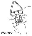
グリップ付属品の別の実施例は、運動器具100のグリップ123に取り付けられた場合の3つの異なる運動を示す図19A乃至19Cに説明されているフィンガーグリップ付属品1900である。フィンガーグリップアセンブリ1900は、親指と1又はそれ以上の指で受けて把持されるように構成される環状部1910と、付属品を運動器具のグリップに取り付けるためのグリップ取付部1920とを具える。グリップ取付部1920は、対のグリップ123の1つに取り外し可能に取付けることができる。一実施例では、2つの環状部1910:第1の環状部1910a及び第2の環状部1910bを有する。フィンガーグリップ付属品1900が固定されている場合、指F1は、例えば、図19Aに示される第1の環状部1910aなどの環状部の1つを通して配置されてもよく、指F1は第1の環状部を通して、指F2は図19Bに示されるように第2の環状部1910bを通って配置されてもよく、F1及びF2が、第1の環状部を通って配置されて、指F3及び指F4が、図19Cに示されるように、第2の環状部を通って配置されてもよい。
Another example of a grip accessory is the
一実施例では、対のグリップ123は、それぞれ、1のフィンガーグリップ付属品1900を具えている。1又は複数の指を少なくとも1の環状部1910を通して配置すると、運動器具100に対して引っ張ることによって、力をかけることができる。フィンガーグリップ付属品1900は、フィンガーグリップ4001と同じ機能を有する。
In one embodiment, each pair of
フィンガーグリップ付属品1900の特定の実施例が、図20A乃至Cに説明されており、図20Aは、フィンガーグリップ付属品の斜視図、図20Bは、フィンガーグリップ付属品の20B−20Bの上面図、図20Cは、フィンガーグリップ付属品の20C−20Cの断面側面図である。フィンガーグリップ付属品1900は、第1の環状部1910a及び第2の環状部1910bの2つの環状部1910と、3つの部分1920a、1920b、及び1920cのグリップ取付部1920とを具える。さらに、具体的には、フィンガーグリップ付属品1900は、5つのストラップ:環状ストラップ2001、3つの取付ストラップ1803、及び裏ストラップ2003から形成される。次に記載されているように、5つのストラップが取り付けられることによって、環状ストラップ2001は、1又はそれ以上の指をそれぞれ受けることができる第1の環状部1910a及び指環状部1910bを形成し、3つの取付ストラップ1803は、それぞれ、グリップ取付部1920a、1920b、及び1920cの1つを形成する。フィンガーグリップ1900の大部分は、ハンドグリップ1700と同じ材料で作られることが好ましい。
A specific example of a
好適な実施例では、環状ストラップ2001は、長さ21.5インチで幅1インチの高分子繊維帯から構成され、裏ストラップ2003は、長さ2インチで幅1インチの高分子繊維帯であることが好ましい。好適な取付ストラップ1803は、前述されている。フィンガーグリップ1900は、それぞれ、3つの取付ストラップ1803の1つを通って、環状ストラップ2001及び裏ストラップ2003を通る3つの縫い目2007によって連結されている。好適な実施例では、縫い目2007は、2重縫い部分である。図20A及び20Cに示されているように、環状ストラップ2001の一部は、環状部1910a及び1910bを形成するように3つの取付ストラップ1803のそれぞれの間から出ている。環状部1910a及び1910bは、長さがおよそ8インチの環状ストラップ1901で形成されることが好ましい。環状ストラップ2001は、隣接する取付ストラップ1803の間の2つの環状部1910a及び1910bを具えて、裏ストラップ2003の長さ方向に延在することが好ましい。
In a preferred embodiment, the
フィンガーグリップ付属品1900は、取り外し可能に取付けることができ、以下のように使用される。フィンガーグリップ付属品1900のグリップ取付部1920は、各ストラップ1803の取付面1809と1813を接触させることによって、対のグリップ123の1つに取り外し可能に取付けることができる。フィンガーグリップ付属品1900が固定されている場合、指は、例えば、図20Aに示される環状部1910aなどの環状部の1つを通して配置されてもよく、1本の指が、図20Bに示されるように、それぞれ、環状部1910a及び1910bを通って配置されてもよいし、2本の指が、図20Cに示されるように、環状部1910a及び1910bのそれぞれを通って配置されてもよい。1又は複数の指を少なくとも1の環状部1910を通して配置すると、運動器具100に対してユーザによって、力をかけることができる。
The
グリップ付属品の第3の実施例は、図21A乃至21Cに説明されているように、運動器具100のグリップ123に取り付けられるグリップ付属品2100である。グリップ付属品2100は、次に説明されているように、様々な組み合わせで把持される何本かの紐2110と、グリップ取付部2120とを具える。一般的に、紐2110の数は、1本から5本かそれ以上、好ましくは4本であり、各紐は、同じ直径と長さを有するようにできる。また、紐は、例えば4インチから6インチまでの長さの、十分に人の手で把持可能な長さを有し、図21A乃至21Cに説明されるように、さらに、十分に紐の間にユーザの手を通すことができる長さであることが好ましい。一実施例では、グリップ付属品2100は、第1の紐2110a、第2の紐2110b、第3の紐2110c、第4の紐2110dとして示される4本の紐を具える。紐は、ほとんどどんな組み合わせでも把持できるので、ユーザは、1本から4本全ての紐まで、様々な数の紐を把持できる。図21Aは、例えば、第1の紐2110a、第2の紐2110b、及び第3の紐2110cの3本の紐を把持する手Hを示し、図21Bは、例えば、第1の及び第2の紐の2本の紐を把持する手を示し、そして、図21Cは、例えば、第1の紐である1本の紐を把持する手を示している。
A third example of a grip accessory is a
グリップ取付部2120は、次に説明するように、対のグリップ123の1つに取り外し可能に取付けることができる。グリップ付属品2100が固定されると、1から全ての紐2210の間を握って、運動器具100に対して引っ張ることによって、力をかけることができる。一実施例では、対のグリップ123のそれぞれは、1のグリップ付属品2100を設けている。
The
グリップ付属品2100の特定の実施例が、図22A乃至Dに示されており、図22Aは、グリップ付属品の斜視図、図22Bはグリップ付属品の上面図、図22Cは、グリップ付属品の底面図、図22Dは、図22Cの22D−22Dの断面図である。グリップ付属品2100は、4つのストラップ、具体的には、裏ストラップ2205、前ストラップ2207、及び2つの取付ストラップ1803と、2本の紐2201及び2203とを具える。紐2110は、2本の長い紐2201及び2203から形成され、グリップ取付部2120は、ストラップ2205、2207、及び1803から形成される。
A specific example of a
グリップ取付部2120を形成する2つのストラップ1803は、裏ストラップ2205と前ストラップ2207の端部の間でそれぞれこれらの中央部に取り付けられる。4本の紐2110a乃至dは、長い紐2201及び2203から形成される。具体的には、図22Bに示されるように、紐2101及び2103は、並んで、半分に折り畳まれている。各紐は、端止め2109で互いに結ばれている両方の紐によって、紐2101及び2103の中間部近くでループ2213を形成し、そして端止め2109によって結ばれる紐2201及び2203の4つの端部によって、ループ2113を形成する。断面図、図22Dでは、紐2203は、端止め2209で互いに結ばれている第1の端部2213と、第2の端部2217と、ストラップ2207周りにループ2213を形成している中央部2215とを具えて示されている。各紐2101及び2103は、半分で折り畳まれており、このようにして、各紐は、端止め2209と2111の間で2本の紐を形成している。具体的には、紐2101は、紐2210aと2210bを形成し、紐2103は、紐2210cと2210dとを形成する。
The two
ストラップ2105及び2107は、好ましくは高分子繊維帯である。裏ストラップ2105は、長さ5インチで幅1インチ、前ストラップ2107は、長さ6インチで幅1インチであることが好ましい。紐2101及び2103は、長さ約20インチから約30インチ、さらに好ましくは約22インチから約26インチ、より好ましくは、約24インチの綿紐であることが好ましい。紐2101及び2103の直径は、好ましくは、1/2インチから1インチ、さらに好ましくは約3/4インチであることが好ましい。ストラップ2105及び2107と取付ストラップ1803の間の連結部は、2重に縫い合わせられていることが好ましい。得られたグリップ取付部2100は、およそ10インチの把持可能な長さの4本の紐を具え、グリップ紐2110の間に人の手を通すことができる十分な空間をもたせる。
Straps 2105 and 2107 are preferably polymeric fiber bands. The back strap 2105 is preferably 5 inches long and 1 inch wide, and the front strap 2107 is preferably 6 inches long and 1 inch wide. The strings 2101 and 2103 are preferably cotton strings of about 20 inches to about 30 inches in length, more preferably about 22 inches to about 26 inches, and more preferably about 24 inches. The cords 2101 and 2103 preferably have a diameter of ½ inch to 1 inch, more preferably about 3/4 inch. It is preferable that the connection part between the straps 2105 and 2107 and the
グリップ付属品2100は、取り外し可能に取付けることができ、以下のように使用される。グリップ取付部2120は、各ストラップ1803の取付面1809と1813を接触させることによって、対のグリップ123の1つに取り外し可能に取付けることができる。フィンガーグリップ付属品2100が固定されている場合、1本、2本、3本、又は4本全ての紐2110a乃至dが手で把持されてもよい。例えば、図22Aは、ユーザによって把持される紐2110a、2110b、及び2110cを示し、図22Bは、ユーザによって把持される紐2110a、及び2110bを示し、図22Cは、ユーザによって把持される紐2110aを示している。紐2110が把持されているので、運動器具100に対してユーザが力を加えることができる。
The
ここに説明されている発明は、ある好適な実施例及び実施例との関係で開示されているが、当業者は、具体的に開示された実施例を越えて、他の代替の本発明の実施例および/または使用、及びこれらの明らかな改良及び均等物まで拡大して本発明が適用されることを理解するであろう。従って、ここに開示されている本発明の範囲は上述した特定の実施例によって制限されるべきではなく、以下の請求の範囲の正確な解釈によってのみ決定されるべきである。 Although the invention described herein has been disclosed in connection with certain preferred embodiments and embodiments, those skilled in the art will be able to go beyond the specifically disclosed embodiments to other alternative embodiments of the invention. It will be understood that the invention applies to examples and / or uses and extends to obvious improvements and equivalents thereof. Accordingly, the scope of the invention disclosed herein should not be limited by the specific embodiments described above, but should be determined only by an accurate interpretation of the following claims.
Claims (25)
第1のループを具える少なくとも1つの端部を有する非弾性部と;
前記第1のループに取り付けられるハンドグリップと;
前記ハンドグリップに取り付けられる第2のループとを具え、
前記第1のループは前記第2のループから分離し、
前記第2のループは、前記ハンドグリップを通過する連続的なループであり、
前記ハンドグリップは、前記少なくとも1つの端部に一体的に取り付けられ、
前記第2のループは、前記少なくとも1つの端部に一体的に取り付けられ、
前記運動器具は、前記ハンドグリップ、前記第2のループ、またはそれらのいくつかの組合せによって前記運動器具のユーザの重量を支持するよう適合されていることを特徴とする運動器具。 In exercise equipment:
An inelastic portion having at least one end comprising a first loop;
A hand grip attached to the first loop;
A second loop attached to the hand grip;
The first loop separates from the second loop;
The second loop is a continuous loop passing through the handgrip;
The hand grip is integrally attached to the at least one end;
The second loop is integrally attached to the at least one end;
The exercise device is adapted to support the weight of a user of the exercise device by the hand grip, the second loop, or some combination thereof.
第1のループを具える少なくとも1つの端部を有する非弾性部と;An inelastic portion having at least one end comprising a first loop;
前記第1のループに取り付けられるハンドグリップと;A hand grip attached to the first loop;
前記ハンドグリップに取り付けられる第2のループとを具え、A second loop attached to the hand grip;
前記第1のループは前記第2のループから分離し、The first loop separates from the second loop;
前記第2のループは、前記ハンドグリップを通過する連続的なループであり、The second loop is a continuous loop passing through the handgrip;
前記ハンドグリップは、前記少なくとも1つの端部に一体的に取り付けられ、The hand grip is integrally attached to the at least one end;
前記第2のループは、前記ハンドグリップに一体的に取り付けられ、The second loop is integrally attached to the hand grip;
前記運動器具は、前記ハンドグリップ、前記第2のループ、またはそれらのいくつかの組合せによって前記運動器具のユーザの重量を支持するよう適合されていることを特徴とする運動器具。The exercise device is adapted to support the weight of a user of the exercise device by the hand grip, the second loop, or some combination thereof.
第1のループを具える少なくとも1つの端部を有する非弾性部と;An inelastic portion having at least one end comprising a first loop;
前記第1のループに取り付けられるハンドグリップと;A hand grip attached to the first loop;
前記ハンドグリップに取り付けられる第2のループとを具え、A second loop attached to the hand grip;
前記第1のループは前記第2のループから分離し、The first loop separates from the second loop;
前記第2のループは、前記ハンドグリップを通過する連続的なループであり、The second loop is a continuous loop passing through the handgrip;
前記第2のループは、前記少なくとも1つの端部に一体的に取り付けられ、The second loop is integrally attached to the at least one end;
前記運動器具は、前記ハンドグリップ、前記第2のループ、またはそれらのいくつかの組合せによって前記運動器具のユーザの重量を支持するよう適合されていることを特徴とする運動器具。The exercise device is adapted to support the weight of a user of the exercise device by the hand grip, the second loop, or some combination thereof.
第1のループを具える第1の端部及び第2のループを具える第2の端部を有する非弾性部と;An inelastic portion having a first end comprising a first loop and a second end comprising a second loop;
前記第1の端部に取り付けられる第1のハンドグリップと;A first hand grip attached to the first end;
前記第1の端部に取り付けられる第3のループと;A third loop attached to the first end;
前記第2の端部に取り付けられる第2のハンドグリップと;A second hand grip attached to the second end;
前記第2の端部に取り付けられる第4のループとを具え、A fourth loop attached to the second end;
前記第3のループは前記第1のループから分離し、前記第1のハンドグリップを通る固定された長さの連続的なループであり、The third loop is a fixed length continuous loop that separates from the first loop and passes through the first hand grip;
前記第4のループは前記第2のループから分離し、前記第2のハンドグリップを通る連続的なループであり、The fourth loop is a continuous loop that separates from the second loop and passes through the second handgrip;
前記第1のハンドグリップは前記第1の端部に一体的に取り付けられ、前記第2のハンドグリップは前記第2の端部に一体的に取り付けられ、The first hand grip is integrally attached to the first end; the second hand grip is integrally attached to the second end;
前記第3のループは前記第1の端部に一体的に取り付けられ、The third loop is integrally attached to the first end;
前記運動器具は前記ハンドグリップ、前記ループ、またはそれらのいくつかの組合わせによって前記運動器具のユーザの重量を支持するよう適合されていることを特徴とする運動器具。The exercise device is adapted to support the weight of a user of the exercise device by the hand grip, the loop, or some combination thereof.
第1のループを具える第1の端部及び第2のループを具える第2の端部を有する非弾性部と;An inelastic portion having a first end comprising a first loop and a second end comprising a second loop;
前記第1の端部に取り付けられる第1のハンドグリップと;A first hand grip attached to the first end;
前記第1の端部に取り付けられる第3のループと;A third loop attached to the first end;
前記第2の端部に取り付けられる第2のハンドグリップと;A second hand grip attached to the second end;
前記第2の端部に取り付けられる第4のループとを具え、A fourth loop attached to the second end;
前記第3のループは前記第1のループから分離し、前記第1のハンドグリップを通る固定された長さの連続的なループであり、The third loop is a fixed length continuous loop that separates from the first loop and passes through the first hand grip;
前記第4のループは前記第2のループから分離し、前記第2のハンドグリップを通る連続的なループであり、The fourth loop is a continuous loop that separates from the second loop and passes through the second handgrip;
前記第1のハンドグリップは前記第1の端部に一体的に取り付けられ、前記第2のハンドグリップは前記第2の端部に一体的に取り付けられ、The first hand grip is integrally attached to the first end; the second hand grip is integrally attached to the second end;
前記第3のループは前記第1のハンドグリップに一体的に取り付けられ、The third loop is integrally attached to the first hand grip;
前記運動器具は前記ハンドグリップ、前記ループ、またはそれらのいくつかの組合わせによって前記運動器具のユーザの重量を支持するよう適合されていることを特徴とする運動器具。The exercise device is adapted to support the weight of a user of the exercise device by the hand grip, the loop, or some combination thereof.
第1のループを具える第1の端部及び第2のループを具える第2の端部を有する非弾性部と;An inelastic portion having a first end comprising a first loop and a second end comprising a second loop;
前記第1の端部に取り付けられる第1のハンドグリップと;A first hand grip attached to the first end;
前記第1の端部に取り付けられる第3のループと;A third loop attached to the first end;
前記第2の端部に取り付けられる第2のハンドグリップと;A second hand grip attached to the second end;
前記第2の端部に取り付けられる第4のループとを具え、A fourth loop attached to the second end;
前記第3のループは前記第1のループから分離し、前記第1のハンドグリップを通る固定された長さの連続的なループであり、The third loop is a fixed length continuous loop that separates from the first loop and passes through the first hand grip;
前記第4のループは前記第2のループから分離し、前記第2のハンドグリップを通る連続的なループであり、The fourth loop is a continuous loop that separates from the second loop and passes through the second handgrip;
前記第1のハンドグリップは前記第1の端部に一体的に取り付けられ、前記第2のハンドグリップは前記第2の端部に一体的に取り付けられ、The first hand grip is integrally attached to the first end; the second hand grip is integrally attached to the second end;
前記第4のループは前記第2の端部に一体的に取り付けられ、The fourth loop is integrally attached to the second end;
前記運動器具は前記ハンドグリップ、前記ループ、またはそれらのいくつかの組合わせによって前記運動器具のユーザの重量を支持するよう適合されていることを特徴とする運動器具。The exercise device is adapted to support the weight of a user of the exercise device by the hand grip, the loop, or some combination thereof.
第1のループを具える第1の端部及び第2のループを具える第2の端部を有する非弾性部と;An inelastic portion having a first end comprising a first loop and a second end comprising a second loop;
前記第1の端部に取り付けられる第1のハンドグリップと;A first hand grip attached to the first end;
前記第1の端部に取り付けられる第3のループと;A third loop attached to the first end;
前記第2の端部に取り付けられる第2のハンドグリップと;A second hand grip attached to the second end;
前記第2の端部に取り付けられる第4のループとを具え、A fourth loop attached to the second end;
前記第3のループは前記第1のループから分離し、前記第1のハンドグリップを通る固定された長さの連続的なループであり、The third loop is a fixed length continuous loop that separates from the first loop and passes through the first hand grip;
前記第4のループは前記第2のループから分離し、前記第2のハンドグリップを通る連続的なループであり、The fourth loop is a continuous loop that separates from the second loop and passes through the second handgrip;
前記第1のハンドグリップは前記第1の端部に一体的に取り付けられ、前記第2のハンドグリップは前記第2の端部に一体的に取り付けられ、The first hand grip is integrally attached to the first end; the second hand grip is integrally attached to the second end;
前記第4のループは前記第2のハンドグリップに一体的に取り付けられ、The fourth loop is integrally attached to the second hand grip;
前記運動器具は前記ハンドグリップ、前記ループ、またはそれらのいくつかの組合わせによって前記運動器具のユーザの重量を支持するよう適合されていることを特徴とする運動器具。The exercise device is adapted to support the weight of a user of the exercise device by the hand grip, the loop, or some combination thereof.
Applications Claiming Priority (5)
| Application Number | Priority Date | Filing Date | Title |
|---|---|---|---|
| US73414505P | 2005-11-07 | 2005-11-07 | |
| US60/734,145 | 2005-11-07 | ||
| US11/557,050 US7806814B2 (en) | 2003-04-09 | 2006-11-06 | Combination grip for an exercise drive |
| US11/557,050 | 2006-11-06 | ||
| PCT/US2006/060596 WO2007079281A2 (en) | 2005-11-07 | 2006-11-07 | Combination grip for an exercise device |
Publications (3)
| Publication Number | Publication Date |
|---|---|
| JP2009514615A JP2009514615A (en) | 2009-04-09 |
| JP2009514615A5 JP2009514615A5 (en) | 2010-01-07 |
| JP5731099B2 true JP5731099B2 (en) | 2015-06-10 |
Family
ID=39709200
Family Applications (1)
| Application Number | Title | Priority Date | Filing Date |
|---|---|---|---|
| JP2008539168A Active JP5731099B2 (en) | 2005-11-07 | 2006-11-07 | Combination grip for exercise equipment |
Country Status (9)
| Country | Link |
|---|---|
| JP (1) | JP5731099B2 (en) |
| KR (1) | KR101142216B1 (en) |
| CN (1) | CN101325987A (en) |
| BR (1) | BRPI0619689B1 (en) |
| CA (1) | CA2628774C (en) |
| MX (1) | MX2008005833A (en) |
| NZ (1) | NZ568067A (en) |
| RU (1) | RU2407577C2 (en) |
| SG (1) | SG175563A1 (en) |
Families Citing this family (13)
| Publication number | Priority date | Publication date | Assignee | Title |
|---|---|---|---|---|
| KR101009710B1 (en) * | 2010-05-11 | 2011-01-19 | 빅터 리 | Exercise equipment that can do hip-up exercise |
| US8197392B2 (en) | 2010-08-03 | 2012-06-12 | Astone Fitness Ltd. | Suspendible exercise straps |
| EP2608850B1 (en) * | 2010-08-27 | 2018-04-18 | Fitness Anywhere, LLC. | Strap restraint apparatus |
| US9022908B2 (en) * | 2013-03-14 | 2015-05-05 | Hygenic Intangible Property Holding Co. | Exercise device |
| WO2015058066A1 (en) * | 2013-10-17 | 2015-04-23 | Tang Michael Wayne | A fitness device and exercise method for generating opposing muscle resistance |
| CN203763761U (en) * | 2014-04-10 | 2014-08-13 | 张仲甫 | Pull cord exerciser structure |
| US9757604B2 (en) | 2015-08-18 | 2017-09-12 | Matthew Roderick Carter | Multipurpose exercise training device |
| US10898751B2 (en) * | 2017-05-05 | 2021-01-26 | Auster Enterprises Limited | Strap-based exercise system |
| RU184925U1 (en) * | 2018-08-28 | 2018-11-14 | Григорий Иванович Васильев | STRENGTH SIMULATOR |
| KR20210034233A (en) | 2019-09-20 | 2021-03-30 | 조연수 | Interior equipment for door installation |
| KR102270772B1 (en) | 2020-06-23 | 2021-06-28 | 김의택 | Physical instrument for strengthening muscle |
| USD998069S1 (en) | 2021-01-05 | 2023-09-05 | Joshua Hunter | Resistance band sleeve |
| KR102455185B1 (en) | 2021-06-21 | 2022-10-17 | 김의택 | Physical instrument for strengthening muscle |
Family Cites Families (8)
| Publication number | Priority date | Publication date | Assignee | Title |
|---|---|---|---|---|
| CH300351A (en) * | 1952-05-28 | 1954-07-31 | Henry Gehri Fritz | Exercise machine. |
| US4047714A (en) * | 1976-04-15 | 1977-09-13 | Powell Truman W | Push pull type exercising device |
| US4756527A (en) * | 1987-04-14 | 1988-07-12 | Ledbetter Daniel R | Gripping assembly for use with cable exercising equipment |
| US5514057A (en) * | 1992-06-05 | 1996-05-07 | Ciolino; Peter A. | Bathtub exercise platform and exercise method |
| US6102837A (en) * | 1996-08-12 | 2000-08-15 | Vital Visions, Inc. | Rope exercise device |
| KR100424998B1 (en) * | 2001-02-09 | 2004-03-27 | 김팔만 | strength exerciser |
| US7044896B2 (en) * | 2003-04-09 | 2006-05-16 | Fitness Anywhere, Inc. | Exercise device including adjustable, inelastic straps |
| KR200329571Y1 (en) * | 2003-05-10 | 2003-10-10 | 이종화 | Hand joint exercise band |
-
2006
- 2006-11-07 MX MX2008005833A patent/MX2008005833A/en active IP Right Grant
- 2006-11-07 SG SG2011070232A patent/SG175563A1/en unknown
- 2006-11-07 RU RU2008120341/12A patent/RU2407577C2/en active
- 2006-11-07 CA CA2628774A patent/CA2628774C/en active Active
- 2006-11-07 KR KR1020087013681A patent/KR101142216B1/en active IP Right Grant
- 2006-11-07 JP JP2008539168A patent/JP5731099B2/en active Active
- 2006-11-07 NZ NZ568067A patent/NZ568067A/en not_active IP Right Cessation
- 2006-11-07 BR BRPI0619689A patent/BRPI0619689B1/en active IP Right Grant
- 2006-11-07 CN CNA2006800464739A patent/CN101325987A/en active Pending
Also Published As
| Publication number | Publication date |
|---|---|
| RU2008120341A (en) | 2009-12-20 |
| BRPI0619689B1 (en) | 2016-08-23 |
| JP2009514615A (en) | 2009-04-09 |
| CA2628774A1 (en) | 2007-07-12 |
| CA2628774C (en) | 2013-08-20 |
| SG175563A1 (en) | 2011-11-28 |
| RU2407577C2 (en) | 2010-12-27 |
| NZ568067A (en) | 2011-06-30 |
| CN101325987A (en) | 2008-12-17 |
| KR20080071171A (en) | 2008-08-01 |
| BRPI0619689A2 (en) | 2011-10-11 |
| KR101142216B1 (en) | 2012-05-04 |
| MX2008005833A (en) | 2008-10-23 |
Similar Documents
| Publication | Publication Date | Title |
|---|---|---|
| JP5731099B2 (en) | Combination grip for exercise equipment | |
| EP2195096B1 (en) | Inelastic exercise device having a limited range | |
| EP1945319B1 (en) | Combination grip for an exercise device | |
| CA2715413C (en) | Exercise device having inelastic straps and interchangeable parts | |
| CA2634464C (en) | Exercise device with adjustable inelastic straps | |
| RU2483775C2 (en) | Combined anchor for training machine | |
| RU2455044C2 (en) | Combined grip for fitness machine | |
| BRPI0815870B1 (en) | EXERCISE FIXED TO A STRUCTURE |
Legal Events
| Date | Code | Title | Description |
|---|---|---|---|
| A521 | Request for written amendment filed |
Free format text: JAPANESE INTERMEDIATE CODE: A523 Effective date: 20091021 |
|
| A621 | Written request for application examination |
Free format text: JAPANESE INTERMEDIATE CODE: A621 Effective date: 20091021 |
|
| A521 | Request for written amendment filed |
Free format text: JAPANESE INTERMEDIATE CODE: A523 Effective date: 20091110 |
|
| RD04 | Notification of resignation of power of attorney |
Free format text: JAPANESE INTERMEDIATE CODE: A7424 Effective date: 20100407 |
|
| A131 | Notification of reasons for refusal |
Free format text: JAPANESE INTERMEDIATE CODE: A131 Effective date: 20120131 |
|
| A601 | Written request for extension of time |
Free format text: JAPANESE INTERMEDIATE CODE: A601 Effective date: 20120427 |
|
| A602 | Written permission of extension of time |
Free format text: JAPANESE INTERMEDIATE CODE: A602 Effective date: 20120509 |
|
| A521 | Request for written amendment filed |
Free format text: JAPANESE INTERMEDIATE CODE: A523 Effective date: 20120521 |
|
| A711 | Notification of change in applicant |
Free format text: JAPANESE INTERMEDIATE CODE: A711 Effective date: 20120529 |
|
| A521 | Request for written amendment filed |
Free format text: JAPANESE INTERMEDIATE CODE: A821 Effective date: 20120529 |
|
| A131 | Notification of reasons for refusal |
Free format text: JAPANESE INTERMEDIATE CODE: A131 Effective date: 20130305 |
|
| A131 | Notification of reasons for refusal |
Free format text: JAPANESE INTERMEDIATE CODE: A131 Effective date: 20140311 |
|
| A601 | Written request for extension of time |
Free format text: JAPANESE INTERMEDIATE CODE: A601 Effective date: 20140610 |
|
| A602 | Written permission of extension of time |
Free format text: JAPANESE INTERMEDIATE CODE: A602 Effective date: 20140620 |
|
| A521 | Request for written amendment filed |
Free format text: JAPANESE INTERMEDIATE CODE: A523 Effective date: 20140709 |
|
| TRDD | Decision of grant or rejection written | ||
| A01 | Written decision to grant a patent or to grant a registration (utility model) |
Free format text: JAPANESE INTERMEDIATE CODE: A01 Effective date: 20150317 |
|
| A61 | First payment of annual fees (during grant procedure) |
Free format text: JAPANESE INTERMEDIATE CODE: A61 Effective date: 20150409 |
|
| R150 | Certificate of patent or registration of utility model |
Ref document number: 5731099 Country of ref document: JP Free format text: JAPANESE INTERMEDIATE CODE: R150 |
|
| R250 | Receipt of annual fees |
Free format text: JAPANESE INTERMEDIATE CODE: R250 |
|
| R250 | Receipt of annual fees |
Free format text: JAPANESE INTERMEDIATE CODE: R250 |
|
| R250 | Receipt of annual fees |
Free format text: JAPANESE INTERMEDIATE CODE: R250 |
|
| R250 | Receipt of annual fees |
Free format text: JAPANESE INTERMEDIATE CODE: R250 |
|
| R250 | Receipt of annual fees |
Free format text: JAPANESE INTERMEDIATE CODE: R250 |
|
| R250 | Receipt of annual fees |
Free format text: JAPANESE INTERMEDIATE CODE: R250 |
|
| R250 | Receipt of annual fees |
Free format text: JAPANESE INTERMEDIATE CODE: R250 |